Manganese Oxide/Carbon Yolk Shell Nanorod Anodes...
7
Manganese Oxide/Carbon Yolk−Shell Nanorod Anodes for High Capacity Lithium Batteries Zhengyang Cai, †,§ Lin Xu, †,‡,§ Mengyu Yan, † Chunhua Han, † Liang He,* ,† Kalele Mulonda Hercule, † Chaojiang Niu, † Zefan Yuan, † Wangwang Xu, † Longbing Qu, † Kangning Zhao, † and Liqiang Mai* ,† † State Key Laboratory of Advanced Technology for Materials Synthesis and Processing, WUT-Harvard Joint Nano Key Laboratory, Wuhan University of Technology, Wuhan 430070, China ‡ Department of Chemistry and Chemical Biology, Harvard University, Cambridge, Massachusetts 02138, United States * S Supporting Information ABSTRACT: Transition metal oxides have attracted much interest for their high energy density in lithium batteries. However, the fast capacity fading and the low power density still limit their practical implementation. In order to overcome these challenges, one-dimensional yolk−shell nanorods have been successfully constructed using manganese oxide as an example through a facile two-step sol−gel coating method. Dopamine and tetraethoxysilane are used as precursors to obtain uniform polymer coating and silica layer followed by converting into carbon shell and hollow space, respectively. As anode material for lithium batteries, the manganese oxide/ carbon yolk−shell nanorod electrode has a reversible capacity of 660 mAh/g for initial cycle at 100 mA/g and exhibits excellent cyclability with a capacity of 634 mAh/g after 900 cycles at a current density of 500 mA/g. An enhanced capacity is observed during the long-term cycling process, which may be attributed to the structural integrity, the stability of solid electrolyte interphase layer, and the electrochemical actuation of the yolk−shell nanorod structure. The results demonstrate that the manganese oxide is well utilized with the one-dimensional yolk−shell structure, which represents an efficient way to realize excellent performance for practical applications. KEYWORDS: Yolk−shell nanorod, manganese oxide, long-life, volume change, anode material R ecently, lithium batteries have been widely developed to meet the demands of a variety of energy applications, such as grid storage, hybrid electric vehicles, and portable electronic devices because of their high energy density and long lifespan. 1−5 As is known to all, electrode materials play an important role in battery performance. Commercially used graphite anode materials deliver a specific capacity of 372 mAh/ g. 6,7 To meet the enormous demands of energy consumptions, a material with higher capacity is required. 8−12 Compared with conventional graphite materials, transition metal oxide materials based on conversion reaction mechanism such as cobalt oxides, copper oxides, iron oxides, etc., have shown high reversible capacity. 13−16 Among them, Mn 3 O 4 has attracted the most attention for its natural abundance, no toxicity, cost effectiveness, and high theoretical capacity, making it a promising anode material for high performance lithium batteries. 17−19 However, poor rate performance and rapid capacity decays during cycling still exist for Mn 3 O 4 . These drawbacks may be ascribed to the following: (1) extremely low electrical conductivity (∼10 −7 −10 −8 S/cm) 20 and (2) signifi- cant volume change during the lithium insertion/extraction process in manganese oxide, which leads to the degradation of the mechanical integrity and the instability of the solid electrolyte interphase (SEI). 6,8 In spite of the disappointing results, great efforts have been made to optimize the performance of manganese oxide electrode by carbon coating, morphology control, and selective growth method. 20−27 Presently, yolk−shell nanostructure, a new class of architecture, has attracted great attention in various applica- tions, especially in the field of lithium batteries. 28 The yolk− shell structure in combination with carbon shell can provide a new strategy to solve some drawbacks existing in anode materials, such as the large volume change, low conductivity, and poor cycling performance. Recently, some efforts have been made to explore this kind of structure. Cui and co-workers 29 have designed a Si/void/C nanoparticle electrode by using SiO 2 as the sacrificial template, it delivers a capacity as high as 2000 mAh/g after 50 cycles, which is several times larger than that of Si/C nanoparticle electrode. Moreover, the yolk−shell structure is also suitable for transition metal oxides. Lou and co- workers 30 have successfully developed a general route for the synthesis of ternary ZnMn 2 O 4 ball-in-ball hollow structure, Received: November 18, 2014 Published: December 9, 2014 Letter pubs.acs.org/NanoLett © 2014 American Chemical Society 738 dx.doi.org/10.1021/nl504427d | Nano Lett. 2015, 15, 738−744
Transcript of Manganese Oxide/Carbon Yolk Shell Nanorod Anodes...
Manganese Oxide/Carbon Yolk−Shell Nanorod Anodes for HighCapacity Lithium BatteriesZhengyang Cai,†,§ Lin Xu,†,‡,§ Mengyu Yan,† Chunhua Han,† Liang He,*,† Kalele Mulonda Hercule,†
Chaojiang Niu,† Zefan Yuan,† Wangwang Xu,† Longbing Qu,† Kangning Zhao,† and Liqiang Mai*,†
†State Key Laboratory of Advanced Technology for Materials Synthesis and Processing, WUT-Harvard Joint Nano Key Laboratory,Wuhan University of Technology, Wuhan 430070, China‡Department of Chemistry and Chemical Biology, Harvard University, Cambridge, Massachusetts 02138, United States
*S Supporting Information
ABSTRACT: Transition metal oxides have attracted muchinterest for their high energy density in lithium batteries.However, the fast capacity fading and the low power densitystill limit their practical implementation. In order to overcomethese challenges, one-dimensional yolk−shell nanorods havebeen successfully constructed using manganese oxide as anexample through a facile two-step sol−gel coating method.Dopamine and tetraethoxysilane are used as precursors toobtain uniform polymer coating and silica layer followed byconverting into carbon shell and hollow space, respectively. Asanode material for lithium batteries, the manganese oxide/carbon yolk−shell nanorod electrode has a reversible capacityof 660 mAh/g for initial cycle at 100 mA/g and exhibitsexcellent cyclability with a capacity of 634 mAh/g after 900 cycles at a current density of 500 mA/g. An enhanced capacity isobserved during the long-term cycling process, which may be attributed to the structural integrity, the stability of solid electrolyteinterphase layer, and the electrochemical actuation of the yolk−shell nanorod structure. The results demonstrate that themanganese oxide is well utilized with the one-dimensional yolk−shell structure, which represents an efficient way to realizeexcellent performance for practical applications.
KEYWORDS: Yolk−shell nanorod, manganese oxide, long-life, volume change, anode material
Recently, lithium batteries have been widely developed tomeet the demands of a variety of energy applications, such
as grid storage, hybrid electric vehicles, and portable electronicdevices because of their high energy density and longlifespan.1−5 As is known to all, electrode materials play animportant role in battery performance. Commercially usedgraphite anode materials deliver a specific capacity of 372 mAh/g.6,7 To meet the enormous demands of energy consumptions,a material with higher capacity is required.8−12 Compared withconventional graphite materials, transition metal oxide materialsbased on conversion reaction mechanism such as cobalt oxides,copper oxides, iron oxides, etc., have shown high reversiblecapacity.13−16 Among them, Mn3O4 has attracted the mostattention for its natural abundance, no toxicity, costeffectiveness, and high theoretical capacity, making it apromising anode material for high performance lithiumbatteries.17−19 However, poor rate performance and rapidcapacity decays during cycling still exist for Mn3O4. Thesedrawbacks may be ascribed to the following: (1) extremely lowelectrical conductivity (∼10−7−10−8 S/cm)20 and (2) signifi-cant volume change during the lithium insertion/extractionprocess in manganese oxide, which leads to the degradation ofthe mechanical integrity and the instability of the solid
electrolyte interphase (SEI).6,8 In spite of the disappointingresults, great efforts have been made to optimize theperformance of manganese oxide electrode by carbon coating,morphology control, and selective growth method.20−27
Presently, yolk−shell nanostructure, a new class ofarchitecture, has attracted great attention in various applica-tions, especially in the field of lithium batteries.28 The yolk−shell structure in combination with carbon shell can provide anew strategy to solve some drawbacks existing in anodematerials, such as the large volume change, low conductivity,and poor cycling performance. Recently, some efforts have beenmade to explore this kind of structure. Cui and co-workers29
have designed a Si/void/C nanoparticle electrode by using SiO2
as the sacrificial template, it delivers a capacity as high as 2000mAh/g after 50 cycles, which is several times larger than that ofSi/C nanoparticle electrode. Moreover, the yolk−shell structureis also suitable for transition metal oxides. Lou and co-workers30 have successfully developed a general route for thesynthesis of ternary ZnMn2O4 ball-in-ball hollow structure,
Received: November 18, 2014Published: December 9, 2014
Letter
pubs.acs.org/NanoLett
© 2014 American Chemical Society 738 dx.doi.org/10.1021/nl504427d | Nano Lett. 2015, 15, 738−744
which shows significantly enhanced electrochemical perform-ance when used as anode material for lithium batteries. Despitethe great successes, previous works mainly focused on zerodimensional yolk−shell nanoparticles.31−34 Recently, novelone-dimensional nanostructure has shown great potential inenergy storage, nanoelectronics fields, etc.35−40 Therefore, one-dimensional yolk−shell structure with more active reaction sitesand shorter diffusion paths will be of great benefit for lithiumbatteries. Nevertheless, this unique structure has seldom beenreported,41−43 partly the reason being that it is difficult to maketwo uniform coating layers around the structure, especially fortransition metal oxide.In this Letter, taking manganese oxides as an example, we
designed and synthesized novel yolk−shell nanorods using sol−gel method with both high specific capacity and long cyclecapability for lithium batteries. The synthesis procedure ismainly composed of four steps as illustrated in Figure 1a.44 Inthis structure, the core is manganese oxide nanorod consistingof small particles, while the shell is carbon, which allows lithiumion to pass through, and the void space between manganeseoxide and carbon can buffer the volume change during thelithium ion insertion/extraction process.The yolk−shell nanorod structure possesses several unique
properties as anode material: (1) the one-dimensional yolk−shell nanorod materials have more active reaction sites causedby higher Brunauer−Emmett−Teller (BET) surface area of30.9 m2/g, shorter diffusion paths for both lithium ions andelectrons providing faster redox reactions;45 (2) the internalstress induced by large volume changes during the lithiuminsertion/extraction process can be buffered through theavailable void spaces around, and thus pulverization andcollapse can be prevented and a stable structure is obtained;(3) since the relationship between the stability of SEI and theelectrochemical performance of lithium batteries has beenreported,46 the SEI formed around the carbon shell at the firstcycle can keep stable because the expanded manganese oxidecore may not disturb the carbon shell;29,47 (4) good
conductivity can be realized for the composite material becausethe carbon shell is a good electronic conductor. All of thesefacts make manganese oxide/carbon yolk−shell a promisinganode material for practical applications.The crystal structure of the as-prepared sample was
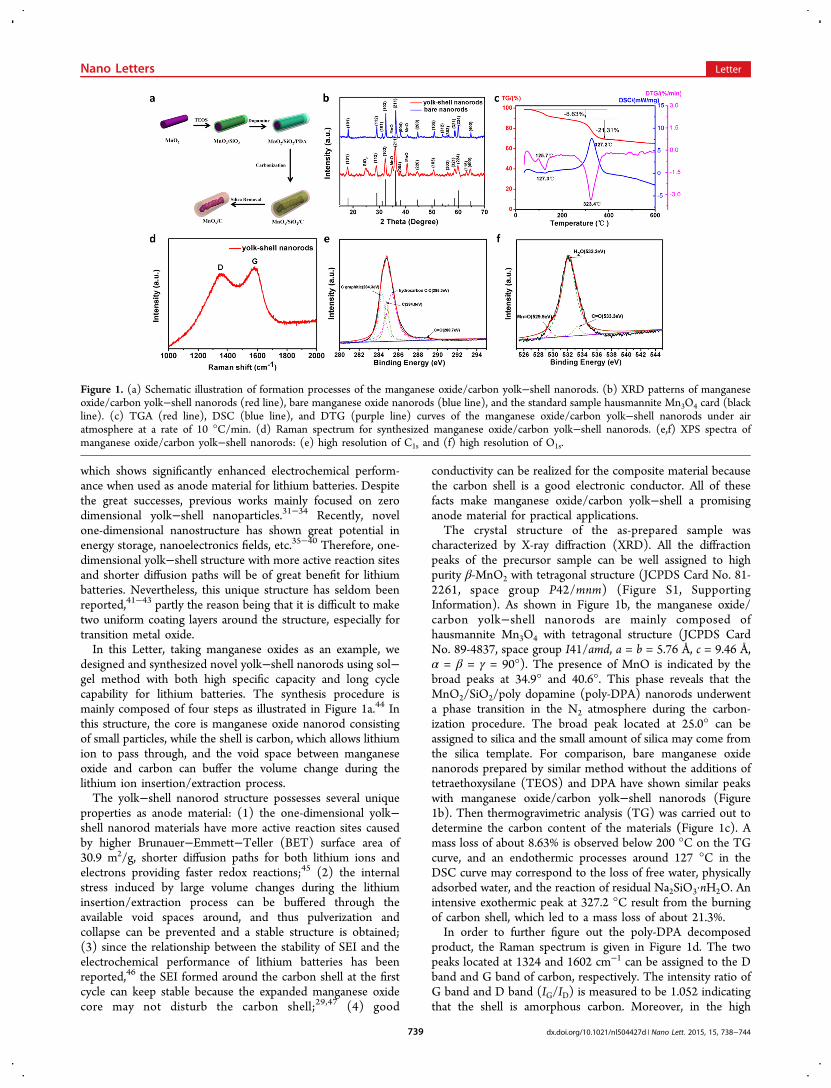
characterized by X-ray diffraction (XRD). All the diffractionpeaks of the precursor sample can be well assigned to highpurity β-MnO2 with tetragonal structure (JCPDS Card No. 81-2261, space group P42/mnm) (Figure S1, SupportingInformation). As shown in Figure 1b, the manganese oxide/carbon yolk−shell nanorods are mainly composed ofhausmannite Mn3O4 with tetragonal structure (JCPDS CardNo. 89-4837, space group I41/amd, a = b = 5.76 Å, c = 9.46 Å,α = β = γ = 90°). The presence of MnO is indicated by thebroad peaks at 34.9° and 40.6°. This phase reveals that theMnO2/SiO2/poly dopamine (poly-DPA) nanorods underwenta phase transition in the N2 atmosphere during the carbon-ization procedure. The broad peak located at 25.0° can beassigned to silica and the small amount of silica may come fromthe silica template. For comparison, bare manganese oxidenanorods prepared by similar method without the additions oftetraethoxysilane (TEOS) and DPA have shown similar peakswith manganese oxide/carbon yolk−shell nanorods (Figure1b). Then thermogravimetric analysis (TG) was carried out todetermine the carbon content of the materials (Figure 1c). Amass loss of about 8.63% is observed below 200 °C on the TGcurve, and an endothermic processes around 127 °C in theDSC curve may correspond to the loss of free water, physicallyadsorbed water, and the reaction of residual Na2SiO3·nH2O. Anintensive exothermic peak at 327.2 °C result from the burningof carbon shell, which led to a mass loss of about 21.3%.In order to further figure out the poly-DPA decomposed
product, the Raman spectrum is given in Figure 1d. The twopeaks located at 1324 and 1602 cm−1 can be assigned to the Dband and G band of carbon, respectively. The intensity ratio ofG band and D band (IG/ID) is measured to be 1.052 indicatingthat the shell is amorphous carbon. Moreover, in the high
Figure 1. (a) Schematic illustration of formation processes of the manganese oxide/carbon yolk−shell nanorods. (b) XRD patterns of manganeseoxide/carbon yolk−shell nanorods (red line), bare manganese oxide nanorods (blue line), and the standard sample hausmannite Mn3O4 card (blackline). (c) TGA (red line), DSC (blue line), and DTG (purple line) curves of the manganese oxide/carbon yolk−shell nanorods under airatmosphere at a rate of 10 °C/min. (d) Raman spectrum for synthesized manganese oxide/carbon yolk−shell nanorods. (e,f) XPS spectra ofmanganese oxide/carbon yolk−shell nanorods: (e) high resolution of C1s and (f) high resolution of O1s.
Nano Letters Letter
dx.doi.org/10.1021/nl504427d | Nano Lett. 2015, 15, 738−744739

resolution spectrum of C1s (Figure 1e), the sample mainlycontains graphite carbon (284.3 eV) and hydrocarbon (285.3eV). A broad peak observed at 288.7 eV can be attributed to theCO bond, which is consistent with that in the high resolutionspectrum of O1s (Figure 1f). These results, combined withcomparison data (Figure S2, Supporting Information),demonstrate that the poly-DPA converts to amorphous carbonduring the calcining procedure.To investigate the functions of TEOS and DPA in
controllable synthesis and provide the detailed informationon the manganese oxide/carbon yolk−shell nanorods, field
emission scanning electron microscopy (FESEM) and trans-mission electron microscopy (TEM) images are provided. Theuniform MnO2 nanorods with an average diameter of about 90nm and a length of about 2.5 μm were prepared by a simplehydrothermal method (Figure S3a, Supporting Information).MnO2/SiO2 nanorods obtained by the sol−gel process show asmooth surface, and the thickness of the silica shell is about 15nm as shown in the magnified FESEM image (Figure S3b,Supporting Information). Then a DPA self-polymerizationprocess leads to the formation of MnO2/SiO2/poly-DPAnanorods (Figure 2a) with a diameter of about 180 nm,
Figure 2. (a) FESEM image of manganese oxide/silica/polydopamine nanorods. (b,c) FESEM image (b) and TEM image (c) of manganese oxide/carbon yolk−shell nanorods. (d) TEM image of a single manganese oxide/carbon yolk−shell nanorod; the inset shows the HRTEM image of thenanorod with a scale bar of 5 nm. (e) EDS elemental mapping of Mn, O, and C, respectively. (f) FESEM image and corresponding EDS linescanning profiles of Mn (red line), C (blue line), and O (purple line) recorded along the white line.
Figure 3. (a) CV curves of yolk−shell nanorods at a scan rate of 0.1 mV/s in the potential range from 3.0 to 0.01 V vs Li/Li+. (b) Charge−dischargecurves of yolk−shell nanorods at 100 mA/g for different cycles. (c) Cycling performance of yolk−shell nanorods at 100 mA/g. (d) Cyclingperformance of yolk−shell nanorods and bare nanorods at 200 mA/g. (e) Rate performance of yolk−shell nanorods. (f) AC Impedance plots foryolk−shell nanorods and bare nanorods before and after rate performance.
Nano Letters Letter
dx.doi.org/10.1021/nl504427d | Nano Lett. 2015, 15, 738−744740

revealing the presence of about 40 nm thick poly-DPA layer. Itis noted that the uniform, smooth, and coherent coating ofpoly-DPA may be attributed to the fact that DPA can attach tomany kinds of surfaces leading to a strong interaction with thesubstrates.48
Moreover, a rough surface was observed for manganeseoxide/silica/carbon nanorods after the carbonization process at500 °C under the N2 atmosphere (Figure S3c, SupportingInformation). The elemental distribution of the material wasfurther characterized by energy dispersive spectroscopic (EDS)mapping (Figure S4, Supporting Information). After an etchingprocess conducted in NaOH solution to remove the silica layer,the manganese oxide/carbon yolk−shell nanorods wereprepared (Figure 2b). It is clear that the manganese oxidenanorods fracture into nanoparticles during the sinteringprocess, and there is no significant change in size during theprocedure. Detailed information on the structure is observed inTEM images (Figure 2c,d). It provides the evidence that thenanorods possess a yolk−shell structure and the contrastbetween the hollow and solid parts is obviously observed. Fromthe high magnification TEM image, we can see that, thethickness of the carbon shell is about 32 nm, while the averagethickness of the core is about 36 nm. Moreover, the highresolution transmission electron microscopy (HRTEM) image(Figure 2d, inset) displays a lattice fringe with d-spacing of 0.49
nm, corresponding to the (101) plane of tetragonal crystalshown in XRD pattern. The amorphous carbon layer can alsobe observed in the image. Furthermore, EDS elementalmapping and line scanning (Figure 2e,f) clearly confirm thepresence and distribution of Mn, O, and C elements andfurther demonstrate the yolk−shell nanostructure with amanganese oxide core and carbon shell. Particularly, the thickcarbon coating can make the structure robust and stable,30
which may be beneficial to the cycling performance when usedas anode material for lithium batteries. Then bare manganeseoxide nanorods were prepared for comparison (Figure S3d,Supporting Information).Electrochemical performances were characterized for the
manganese oxide/carbon yolk−shell nanorod electrode.49 It isnoted that the capacity is calculated based on the total mass ofthe materials containing carbon shell and manganese oxide coreand the capacity of the carbon shell is very low as shown inFigure S5, Supporting Information. Cyclic voltammetry wastested for 3 cycles at a sweep rate of 0.1 mV/s in the potentialrange from 3.0 to 0.01 V vs Li/Li+ at room temperature. Asdepicted in Figure 3a, in the first cathodic polarization process,a broad peak centered at about 1.15 V and an intense peak atlow potential are attributed to the reduction of manganeseoxide to metallic manganese and the formation of Li2O,
20,50
another cathodic peak located at about 0.75 V corresponds to
Figure 4. (a,b) Three-dimensional view of (a) the bare manganese oxide nanorod and (b) the manganese oxide/carbon yolk−shell nanorod duringlithiation and delithiation processes. The conductive carbon can block the electrolyte and prevent the SEI formation inside the nanorod whileallowing the lithium ions to transport throughout the carbon. (c−f) TEM images of manganese oxide/carbon yolk−shell nanorod before (c) andafter (d−f) electrochemical cycling for 500 cycles. (d) The SEI layer formed around the carbon shell with a thickness of several nanometers. (e) Theyolk−shell nanorods can maintain integrity even after cycling. (f) The distribution of manganese oxide inside the nanorod. (g) Long-life cyclingperformance of manganese oxide/carbon yolk−shell nanorod electrode at 500 mA/g.
Nano Letters Letter
dx.doi.org/10.1021/nl504427d | Nano Lett. 2015, 15, 738−744741

the decomposition of electrolyte and formation of SEI layer onthe surface of electrode materials.21 The peak located at about1.3 V in the first anodic sweep corresponds to the oxidation ofmanganese. For the next scans, the main cathodic peak shifts toabout 0.25 V, indicating an irreversible phase change.Moreover, the curve of the third scan is similar to that of thesecond one, implying a highly reversible property. The similarprofiles of the bare manganese nanorods demonstrate thatsimilar reactions occur during the charge/discharge process(Figure S7a, Supporting Information). Noteworthy, thepresence of MnO phase may not seriously affect theelectrochemical property as a whole (Figure S6, SupportingInformation). The Mn3O4 phase conducts the electrochemicalconversion reaction: Mn3O4 + 8Li+ + 8e− → 3Mn + 4Li2O,with a theoretical capacity of 936 mAh/g based on the equationC = nNA(e/M). Similarly, the MnO phase delivers theelectrochemical conversion reaction MnO + 2Li+ + 2e− →Mn + Li2O, with a theoretical capacity of 755 mAh/g. Thedifference between the two manganese oxide phases is thenumber of transferred electrons, which just leads to a smalldecrease on the theoretical capacity and has no effect on theelectrochemical mechanism.The voltage profiles of different cycles for yolk−shell
nanorod electrode at a current density of 100 mA/g areshown in Figure 3b. The potential plateau in range of 0.2−0.55V corresponds to the lithiation process while that in 1.2−1.5 Vto the delithiation. In the second, 10th, 20th, and 50th cycles,the discharge capacities are 660, 483, 440, and 448 mAh/g,respectively, much higher than that of bare manganese oxideelectrode (Figure S7b, Supporting Information). Moreover, thepotential plateau at around 0.4 V keeps stable even after 50cycles, indicating superior and stable cycling performance. Inaddition, the electrode delivers a capacity of 649 mAh/g evenafter 150 cycles, and the Coulombic efficiency of the electrodeis maintained around 98% in the subsequent cycles (Figure 3c).The cycling performance of the manganese oxide/carbon
yolk−shell nanorod electrode and pure manganese oxidenanorod electrode at current density of 200 mA/g are shownin Figure 3d. A much better cycling stability can be observed forthe yolk−shell nanorod electrode. After 20 cycles, it delivers adischarge capacity of 381 mAh/g, whereas that of baremanganese oxide is just 62 mAh/g. Even after 200 cycles, theyolk−shell nanorod electrode can still reach 509 mAh/g incapacity with slight increase. However, a discharge capacity ofonly 61 mAh/g can be obtained for bare manganese oxideelectrode in the same condition. In addition, after the firstseveral cycles, the Coulombic efficiency can remain at around98.3%, indicating good reversibility of the manganese oxide/carbon yolk−shell nanorods. Also, we provide the averagecapacity based on three batteries for the cycling performance(Figure S8, Supporting Information). Furthermore, in rateperformance tests, the electrode is tested at different charge anddischarge rates ranging from 100 to 2000 mA/g (Figure 3e); itexhibited the capacities of 487, 382, 263, 179, 91, and 474mAh/g, respectively. Remarkably, the capacity is retained at474 mAh/g when the current density returns to 100 mA/g,manifesting excellent rate performance compared to that ofbare manganese oxide nanorods (109 mAh/g).An excellent cycling performance is an important factor for
promising anode materials. In this case, the manganese oxide/carbon yolk−shell nanorod electrode is cycled at variouscurrent densities to investigate the long-life performance. Theelectrode exhibits a capacity of 932 mAh/g at 200 mA/g after
400 cycles and 837 mAh/g at 300 mA/g after 600 cycles(Figure S9, Supporting Information). Even at a high currentdensity of 500 mA/g, the discharge capacity of the manganeseoxide/carbon yolk−shell nanorod electrode is 289 mAh/g after100 cycles. Afterward the capacity increases gradually untilaround 600 cycles and then keeps stable for the subsequentcycles and finally reaches 634 mAh/g after 900 cycles. Theretentive capacity is measured to be 72.5% relative to the initialone (Figure 4g). Compared with previously reportedmanganese oxide/carbonous hybrid materials (Table S1,Supporting Information), the manganese oxide/carbon yolk−shell nanorod electrode shows enhanced reversible capacityafter long-term cycles. Notably, the increased capacity ofmanganese oxide/carbon yolk−shell nanorods is also widelyobserved for many transition metal oxides. This phenomenonmay be attributed to the growth of an electrochemically gel-likepolymer layer, which can enhance lithium ion storage.14,51 Foranother reason, as can be seen from Figure S10, SupportingInformation, the proportion of the total active materials on theinternal surface of the carbon shell increases and the size of themanganese oxide particles reduces, which can be ascribed to theelectrochemically driven reconstruction of the manganeseoxide.52 The phenomenon may enhance the electrochemicalactivity and result in an improved capacity.The above results have shown that the present yolk−shell
nanorod electrode exhibits excellent electrochemical properties.Just as illustrated in Figure 4b, the void space around themanganese oxide allows it to expand without deforming theoverall morphology during lithiation/delithiation process, sothe SEI layer formed outside the nanorod is not rupturedduring cycling and keeps thin (Figure 4c,d).47 However, asshown in Figure 4a, the bare nanorod suffers a repeatedbreaking and formation of SEI layer during cycling leading tothick SEI layers (Figure S11a,b, Supporting Information). Inaddition, the electrochemical impedance spectra (EIS) are alsoprovided to certify the enhanced capacity of yolk−shellnanorods. In the equivalent circuit, Rs represents the resistanceof the electrolyte, Rct represents the charge transfer resistance,and Rf represents the resistance of the SEI film. CPE and Zw arethe double layer capacitance and the Warburg impedance,respectively. All the curves exhibit a semicircle in the highfrequency region followed by a straight line in the lowfrequency region (Figure 3f). The yolk−shell nanorodelectrode shows an initial resistance of 465 Ω and cycledresistance of 89 Ω. The decrease of charge transfer resistanceindicates the activation and improved kinetics of the reaction.Moreover, the values of Rct at the first, 200th, and 500th cyclesalso show similar tendency (Figure S12, Supporting Informa-tion). However, for bare manganese oxide nanorod electrode,the Rct increases. These opposite behaviors can furtherdemonstrate that the electrochemical actuation that occurredduring the charge/discharge cycles can help enhance theconversion reaction and improve the electrochemical activityfor manganese oxide/carbon yolk−shell nanorods,52 and this isevidenced by the strong adhesion of manganese core andcarbon shell after cycles (Figure 4f). Furthermore, the voidspace between manganese oxide core and carbon shell canbuffer the volume change and keep the integrity of the structure(Figures 4e and S11c,d, Supporting Information). Thus, highcapacity and long life are realized for the manganese oxide/carbon yolk−shell nanorod electrode as anode.In summary, the yolk−shell nanorods with manganese oxide
core and carbon shell have been constructed using a facile sol−
Nano Letters Letter
dx.doi.org/10.1021/nl504427d | Nano Lett. 2015, 15, 738−744742

gel method. The one-dimensional manganese oxide/carbonyolk−shell nanorods with carbon around can buffer the volumechange, improve the electronic conductivity, enhance thestability of the electrode, and prevent the SEI layer frombreaking during cycles even at a high rate. It is demonstratedthat the manganese oxide/carbon yolk−shell nanorod electrodeexhibits excellent electrochemical performance in terms ofreversible specific capacity and cycling stability, especially wherea capacity of about 634 mAh/g after 900 cycles has beenrealized. This novel structure can be further extended for otherone-dimensional materials, and it is of great potential for next-generation energy storage and other applications.
■ ASSOCIATED CONTENT*S Supporting InformationAdditional information and figures. This material is availablefree of charge via the Internet at http://pubs.acs.org.
■ AUTHOR INFORMATIONCorresponding Authors*E-mail: [email protected].*E-mail: [email protected] Contributions§These authors contributed equally to this work.
NotesThe authors declare no competing financial interest.
■ ACKNOWLEDGMENTSThis work is supported by the National Natural Basic ResearchProgram of China (2013CB934103 and 2012CB933003), theNational Science Fund for Distinguished Young Scholars(51425204), the International Science and TechnologyCooperation Program of China (2013DFA50840), the NationalNatural Science Foundation of China (51272197 and51302203), the Hubei Science Fund for Distinguished YoungScholars (2014CFA035), the Fundamental Research Funds forthe Central Universities (2013-ZD-7 and 2014-yb-002), and theStudents Innovation and Entrepreneurship Training Program(136601001 and 20131049701002). We are grateful to Prof. C.M. Lieber of Harvard University and Prof. D. Y. Zhao of FudanUniversity for strong support and stimulating discussions.
■ REFERENCES(1) Tarascon, J.-M.; Armand, M. Nature 2001, 414 (6861), 359−367.(2) Dunn, B.; Kamath, H.; Tarascon, J.-M. Science 2011, 334 (6058),928−935.(3) Kang, B.; Ceder, G. Nature 2009, 458 (7235), 190−193.(4) Goodenough, J. B.; Park, K.-S. J. Am. Chem. Soc. 2013, 135 (4),1167−1176.(5) Zhao, Y.; Xu, L.; Mai, L.; Han, C.; An, Q.; Xu, X.; Liu, X.; Zhang,Q. Proc. Natl. Acad. Sci. U.S.A. 2012, 109 (48), 19569−19574.(6) Cabana, J.; Monconduit, L.; Larcher, D.; Palacin, M. R. Adv.Mater. 2010, 22 (35), E170−E192.(7) Ji, J.; Ji, H.; Zhang, L. L.; Zhao, X.; Bai, X.; Fan, X.; Zhang, F.;Ruoff, R. S. Adv. Mater. 2013, 25 (33), 4673−4677.(8) Jiang, J.; Li, Y.; Liu, J.; Huang, X.; Yuan, C.; Lou, X. W. D. Adv.Mater. 2012, 24 (38), 5166−5180.(9) Mahmood, N.; Zhang, C.; Yin, H.; Hou, Y. J. Mater. Chem. A2014, 2 (1), 15−32.(10) Chan, C. K.; Peng, H.; Liu, G.; McIlwrath, K.; Zhang, X. F.;Huggins, R. A.; Cui, Y. Nat. Nanotechnol. 2008, 3 (1), 31−35.(11) Mahmood, N.; Zhang, C.; Hou, Y. Small 2013, 9 (8), 1321−1328.
(12) Xu, J.; Wu, H.; Wang, F.; Xia, Y.; Zheng, G. Adv. Energy Mater.2013, 3 (3), 286−289.(13) Lu, X.; Zhai, T.; Zhang, X.; Shen, Y.; Yuan, L.; Hu, B.; Gong, L.;Chen, J.; Gao, Y.; Zhou, J. Adv. Mater. 2012, 24 (7), 938−944.(14) Grugeon, S.; Laruelle, S.; Dupont, L.; Tarascon, J.-M. Solid StateSci. 2003, 5 (6), 895−904.(15) Zeng, Y.; Hao, R.; Xing, B.; Hou, Y.; Xu, Z. Chem. Commun.2010, 46 (22), 3920−3922.(16) Wu, H.; Xu, M.; Wu, H.; Xu, J.; Wang, Y.; Peng, Z.; Zheng, G. J.Mater. Chem. 2012, 22 (37), 19821−19825.(17) Luo, W.; Hu, X.; Sun, Y.; Huang, Y. ACS Appl. Mater. Interface2013, 5 (6), 1997−2003.(18) Wang, Y.; Wang, Y.; Jia, D.; Peng, Z.; Xia, Y.; Zheng, G. NanoLett. 2014, 14 (2), 1080−1084.(19) Kim, J.-S.; Kim, K.; Cho, W.; Shin, W. H.; Kanno, R.; Choi, J.W. Nano Lett. 2012, 12 (12), 6358−6365.(20) Wang, H.; Cui, L.-F.; Yang, Y.; Sanchez Casalongue, H.;Robinson, J. T.; Liang, Y.; Cui, Y.; Dai, H. J. Am. Chem. Soc. 2010, 132(40), 13978−13980.(21) Wang, C.; Yin, L.; Xiang, D.; Qi, Y. ACS Appl. Mater. Interface2012, 4 (3), 1636−1642.(22) Gao, J.; Lowe, M. A.; Abruna, H. D. Chem. Mater. 2011, 23 (13),3223−3227.(23) Hao, Q.; Wang, J.; Xu, C. J. Mater. Chem. A 2014, 2 (1), 87−93.(24) Li, Y.; Huang, S.; Jin, J.; Cai, Y.; Tan, H.; Wang, H.-E.; VanTendeloo, G.; Su, B. L. Nanoscale 2014, 6, 6819−6827.(25) Guo, J.; Liu, Q.; Wang, C.; Zachariah, M. R. Adv. Funct. Mater.2012, 22 (4), 803−811.(26) Chang, L.; Mai, L.; Xu, X.; An, Q.; Zhao, Y.; Wang, D.; Feng, X.RSC Adv. 2013, 3 (6), 1947−1952.(27) Jiang, H.; Hu, Y.; Guo, S.; Yan, C.; Lee, P. S.; Li, C. ACS Nano2014, 8 (6), 6038−6046.(28) Lai, X.; Li, J.; Korgel, B. A.; Dong, Z.; Li, Z.; Su, F.; Du, J.;Wang, D. Angew. Chem. 2011, 123 (12), 2790−2793.(29) Liu, N.; Wu, H.; McDowell, M. T.; Yao, Y.; Wang, C.; Cui, Y.Nano Lett. 2012, 12 (6), 3315−3321.(30) Zhang, G.; Yu, L.; Wu, H. B.; Hoster, H. E.; Lou, X. W. D. Adv.Mater. 2012, 24 (34), 4609−4613.(31) Liu, J.; Qiao, S. Z.; Chen, J. S.; Lou, X. W. D.; Xing, X.; Lu, G.Q. M. Chem. Commun. 2011, 47 (47), 12578−12591.(32) Chen, S.; Gordin, M. L.; Yi, R.; Howlett, G.; Sohn, H.; Wang, D.Phys. Chem. Chem. Phys. 2012, 14 (37), 12741−12745.(33) Liu, J.; Qiao, S. Z.; Budi Hartono, S.; Lu, G. Q. M. Angew. Chem.2010, 122 (29), 5101−5105.(34) Wang, J.; Li, W.; Wang, F.; Xia, Y.-Y.; Asiri, A. M.; Zhao, D.Nanoscale 2014, 6, 3217−3222.(35) (a) Kim, S.-K.; Day, R. W.; Cahoon, J. F.; Kempa, T. J.; Song,K.-D.; Park, H.-G.; Lieber, C. M. Nano Lett. 2012, 12 (9), 4971−4976.(b) Mai, L.; Tian, X.; Xu, X.; Chang, L.; Xu, L. Chem. Rev. 2014, 114(23), 11828−11862.(36) Yan, H.; Choe, H. S.; Nam, S.; Hu, Y.; Das, S.; Klemic, J. F.;Ellenbogen, J. C.; Lieber, C. M. Nature 2011, 470 (7333), 240−244.(37) Sun, B.; Chen, Z.; Kim, H.-S.; Ahn, H.; Wang, G. J. PowerSources 2011, 196 (6), 3346−3349.(38) Mai, L.; Xu, L.; Han, C.; Xu, X.; Luo, Y.; Zhao, S.; Zhao, Y.Nano Lett. 2010, 10 (11), 4750−4755.(39) Kempa, T. J.; Cahoon, J. F.; Kim, S.-K.; Day, R. W.; Bell, D. C.;Park, H.-G.; Lieber, C. M. Proc. Natl. Acad. Sci. U.S.A. 2012, 109 (5),1407−1412.(40) Jiang, X.; Tian, B.; Xiang, J.; Qian, F.; Zheng, G.; Wang, H.; Mai,L.; Lieber, C. M. Proc. Natl. Acad. Sci. U.S.A. 2011, 108 (30), 12212−12216.(41) Yan, M.; Wang, F.; Han, C.; Ma, X.; Xu, X.; An, Q.; Xu, L.; Niu,C.; Zhao, Y.; Tian, X. J. Am. Chem. Soc. 2013, 135 (48), 18176−18182.(42) Lou, X. W.; Yuan, C.; Archer, L. A. Adv. Mater. 2007, 19 (20),3328−3332.(43) Guan, C.; Wang, X.; Zhang, Q.; Fan, Z.; Zhang, H.; Fan, H. J.Nano Lett. 2014, 14 (8), 4852−4858.
Nano Letters Letter
dx.doi.org/10.1021/nl504427d | Nano Lett. 2015, 15, 738−744743

(44) Methods: MnO2 nanorods were prepared by mixing MnSO4·H2O and (NH4)2S2O8 in deionized water followed by a hydrothermalmethod at 180 °C for 12 h. Then a stober sol−gel coating process wasconducted, where dispersed MnO2 nanorods were coated with a layerof silica to obtain MnO2/silica nanorods using TEOS as precursor.Afterwards, the sample was dissolved in a mix solution containing 2mg/mL DPA and 10 mM TRIS for 5 h to obtain MnO2/silica/poly-DPA nanorods. Moreover, the precursors were carbonized at 500 °Cfor 2 h under a N2 atmosphere to convert the poly-DPA into a carbonlayer to produce MnO2/silica/carbon nanorods. Finally, it is the silicaremoval process, where the silica layer can be etched away by a 1 MNaOH solution to yield the manganese oxide/carbon yolk−shellnanorods. (More details in Supporting Information.) Characterization:XRD measurements were performed by using a Bruker D8 Advance X-ray diffractometer with a nonmonochromated Cu Ka X-ray source.Raman spectra were acquired using a Renishaw RM-1000 laser Ramanmicroscopy system. FESEM images were collected using a JEOL JSM-7100F at an acceleration voltage of 20 kV. TEM and HRTEM imageswere recorded using a JEOL JEM-2100F STEM/EDS microscope.EDS were recorded by using Oxford EDS IE250. XPS analysis wasdone on VG Multilab 2000. BET surface areas were measured usingTristar II 3020 instrument to measure the adsorption of nitrogen.TGA was performed using a Netzsch STA 449F3 simultaneousthermal analyzer at a heating rate of 10 °C/min in air.(45) Lieber, C. M.; Wang, Z. L. MRS Bull. 2007, 32 (02), 99−108.(46) Wu, H.; Chan, G.; Choi, J. W.; Ryu, I.; Yao, Y.; McDowell, M.T.; Lee, S. W.; Jackson, A.; Yang, Y.; Hu, L. Nat. Nanotechnol. 2012, 7(5), 310−315.(47) Liu, N.; Lu, Z.; Zhao, J.; McDowell, M. T.; Lee, H.-W.; Zhao,W.; Cui, Y. Nat. Nanotechnol. 2014, 9 (3), 187−192.(48) Lee, H.; Dellatore, S. M.; Miller, W. M.; Messersmith, P. B.Science 2007, 318 (5849), 426−430.(49) Electrochemical measurements: The electrochemical propertieswere characterized by means of 2016 coin cells using lithium metal foilas the anode. The electrodes were composed of 70% active material,20% acetylene black, and 10% poly(tetrafluoroethylene) (PTFE)binder. The acetylene black is used as a dispersing agent and aconducting additive to ensure the successful grinding of the as-prepared powders to cut into pellets. A solution (1 M) of LiPF6 in EC-DEC (1:1 vol/vol) was used as the electrolyte. The cells wereassembled in an argon filled glovebox. Galvanostatic charge−dischargemeasurements were performed using a multichannel battery testingsystem (LAND CT2001A), and cyclic voltammetry (CV) andelectrochemical impedance spectra (EIS) were performed using anAutolab Potentiostat Galvanostat. All the measurements were carriedout at room temperature.(50) Thackeray, M.; David, W.; Bruce, P.; Goodenough, J. Mater. Res.Bull. 1983, 18 (4), 461−472.(51) Laruelle, S.; Grugeon, S.; Poizot, P.; Dolle, M.; Dupont, L.;Tarascon, J. J. Electrochem. Soc. 2002, 149 (5), A627−A634.(52) Sun, Y.; Hu, X.; Luo, W.; Xia, F.; Huang, Y. Adv. Funct. Mater.2013, 23 (19), 2436−2444.
Nano Letters Letter
dx.doi.org/10.1021/nl504427d | Nano Lett. 2015, 15, 738−744744