SS2100 H2S Analyzer - SpectraSensors · PDF fileExposure to toxic gas (H2S) ... Equipment...
62
SS2100 H 2 S Analyzer Hardware Installation and Maintenance Manual Hardware Installation and Maintenance Manual P/N 4900002227 rev C SS500XP/SS2000XP Gas Analyzer Hardware Installation and Maintenance Manual
Transcript of SS2100 H2S Analyzer - SpectraSensors · PDF fileExposure to toxic gas (H2S) ... Equipment...

SS2100 H2S Analyzer
Hardware Installation and MaintenanceManual
Hardware Installation and MaintenanceManual
P/N 4900002227 rev C
SS500XP/SS2000XPGas Analyzer
Hardware Installation and MaintenanceManual


SS500XP/SS2000XP Gas Analyzer
Hardware Installation and Maintenance Manual
This manual is used with:Firmware v2.51 Operator’s Manual
Products of
4333 W Sam Houston Pkwy N, Suite 100Houston, TX 77043-1223
Tel: 800.619.2861Fax: 713.856.6623
www.spectrasensors.com
Copyright © 2016 SpectraSensors, Inc. No part of this manual may be reproduced inwhole or in part without the express written permission of SpectraSensors, Inc.SpectraSensors reserves the right to change product design and specifications at anytime without prior notice.

Revision History
Revision Engineering Order Date
A EO15711 6/18/2014
B ECR16360 4/12/2016
C ECR16807 9/20/2016

TABLE OF CONTENTS
List of Figures . . . . . . . . . . . . . . . . . . . . . . . . . . . . . . . . . . . . . . . . . . . . . . iii
List of Tables . . . . . . . . . . . . . . . . . . . . . . . . . . . . . . . . . . . . . . . . . . . . . . . .v
1: Introduction Who Should Read This Manual . . . . . . . . . . . . . . . . . . . . . . . . . . . . . . . . . . . . 1-1How to Use This Manual. . . . . . . . . . . . . . . . . . . . . . . . . . . . . . . . . . . . . . . . . 1-1
General Warnings and Cautions . . . . . . . . . . . . . . . . . . . . . . . . . . . . . . . . . 1-1Equipment Safety Labels . . . . . . . . . . . . . . . . . . . . . . . . . . . . . . . . . . 1-1Instructional Symbols . . . . . . . . . . . . . . . . . . . . . . . . . . . . . . . . . . . . . 1-2
Conventions Used in this Manual . . . . . . . . . . . . . . . . . . . . . . . . . . . . . . . . 1-3SpectraSensors Overview . . . . . . . . . . . . . . . . . . . . . . . . . . . . . . . . . . . . . . . 1-3About the Gas Analyzers . . . . . . . . . . . . . . . . . . . . . . . . . . . . . . . . . . . . . . . . 1-3
Differences between the SS500XP and SS2000XP . . . . . . . . . . . . . . . . . . . . 1-3How the Analyzers Work . . . . . . . . . . . . . . . . . . . . . . . . . . . . . . . . . . . . . . . . 1-4
Wavelength Modulation Spectroscopy (WMS) Signal Detection . . . . . . . . . . . 1-6Getting Familiar with the Analyzer . . . . . . . . . . . . . . . . . . . . . . . . . . . . . . . . . 1-7
2: Installation What Should be Included in the Shipping Box . . . . . . . . . . . . . . . . . . . . . . . . . 2-1Inspecting the Analyzer . . . . . . . . . . . . . . . . . . . . . . . . . . . . . . . . . . . . . . . . . 2-1Installing the Analyzer. . . . . . . . . . . . . . . . . . . . . . . . . . . . . . . . . . . . . . . . . . 2-1
Hardware and Tools for Installation . . . . . . . . . . . . . . . . . . . . . . . . . . . . . . 2-2Hardware. . . . . . . . . . . . . . . . . . . . . . . . . . . . . . . . . . . . . . . . . . . . . . 2-2Tools . . . . . . . . . . . . . . . . . . . . . . . . . . . . . . . . . . . . . . . . . . . . . . . . . 2-2
Lifting/carrying the analyzer . . . . . . . . . . . . . . . . . . . . . . . . . . . . . . . . . . . 2-2Mounting the Analyzer . . . . . . . . . . . . . . . . . . . . . . . . . . . . . . . . . . . . . . . 2-3
Connecting Electrical Power to the Analyzer . . . . . . . . . . . . . . . . . . . . . . . . . . . 2-3Connecting the Output Signals . . . . . . . . . . . . . . . . . . . . . . . . . . . . . . . . . . . . 2-5Changing the 4-20 mA Current Loop Mode. . . . . . . . . . . . . . . . . . . . . . . . . . . . 2-8Connecting the Gas Lines. . . . . . . . . . . . . . . . . . . . . . . . . . . . . . . . . . . . . . . . 2-9Application of Conduit Lubricant . . . . . . . . . . . . . . . . . . . . . . . . . . . . . . . . . . . 2-9
Appendix A: Specifications Spare Parts . . . . . . . . . . . . . . . . . . . . . . . . . . . . . . . . . . . . . . . . . . . . . . . . . A-7
Appendix B: Troubleshooting Potential Risks Affecting Personnel . . . . . . . . . . . . . . . . . . . . . . . . . . . . . . . . . B-1
Mitigating risks . . . . . . . . . . . . . . . . . . . . . . . . . . . . . . . . . . . . . . . . . . . . B-1Exposure to process gases . . . . . . . . . . . . . . . . . . . . . . . . . . . . . . . . . . B-1Exposure to toxic gas (H2S). . . . . . . . . . . . . . . . . . . . . . . . . . . . . . . . . B-1Electrocution hazard . . . . . . . . . . . . . . . . . . . . . . . . . . . . . . . . . . . . . . B-2Explosion hazard . . . . . . . . . . . . . . . . . . . . . . . . . . . . . . . . . . . . . . . . B-2
Gas Leaks . . . . . . . . . . . . . . . . . . . . . . . . . . . . . . . . . . . . . . . . . . . . . . . . . . B-2Contamination . . . . . . . . . . . . . . . . . . . . . . . . . . . . . . . . . . . . . . . . . . . . . . . B-3Excessive Sampling Gas Temperatures and Pressures . . . . . . . . . . . . . . . . . . . . B-3Electrical Noise . . . . . . . . . . . . . . . . . . . . . . . . . . . . . . . . . . . . . . . . . . . . . . . B-4Cleaning the Mirrors . . . . . . . . . . . . . . . . . . . . . . . . . . . . . . . . . . . . . . . . . . . B-4
Tools and Supplies . . . . . . . . . . . . . . . . . . . . . . . . . . . . . . . . . . . . . . . . . . B-4Determining the type of cell mirror . . . . . . . . . . . . . . . . . . . . . . . . . . . . . . B-5
Pressure Sensor Replacement . . . . . . . . . . . . . . . . . . . . . . . . . . . . . . . . . . . . B-8Peak Tracking Reset Procedure. . . . . . . . . . . . . . . . . . . . . . . . . . . . . . . . . . . B-14
Hardware Installation and Maintenance Manual i

SS500XP/SS2000XP Gas Analyzer
Instrument Problems. . . . . . . . . . . . . . . . . . . . . . . . . . . . . . . . . . . . . . . . . . B-14Service Contact . . . . . . . . . . . . . . . . . . . . . . . . . . . . . . . . . . . . . . . . . . . . . B-19
Customer Service. . . . . . . . . . . . . . . . . . . . . . . . . . . . . . . . . . . . . . . . . B-19Before contacting Technical Service . . . . . . . . . . . . . . . . . . . . . . . . . . . . . B-19Service Repair Order . . . . . . . . . . . . . . . . . . . . . . . . . . . . . . . . . . . . . . . B-20
Packing . . . . . . . . . . . . . . . . . . . . . . . . . . . . . . . . . . . . . . . . . . . . . . . . . . . B-20Storage . . . . . . . . . . . . . . . . . . . . . . . . . . . . . . . . . . . . . . . . . . . . . . . . . . . B-21Disclaimers . . . . . . . . . . . . . . . . . . . . . . . . . . . . . . . . . . . . . . . . . . . . . . . . B-21Warranty . . . . . . . . . . . . . . . . . . . . . . . . . . . . . . . . . . . . . . . . . . . . . . . . . . B-21
Index . . . . . . . . . . . . . . . . . . . . . . . . . . . . . . . . . . . . . . . . . . . . . . . . . Index-1
ii 4900002227 rev. C 9-20-16

LIST OF FIGURES
Figure 1–1. Schematic of a typical laser diode absorption spectrometer . . . . . . 1-4Figure 1–2. Typical raw signal from a laser diode absorption spectrometer
with and without mirror contamination . . . . . . . . . . . . . . . . . . . . 1-5Figure 1–3. Typical normalized absorption signal from a laser diode
absorption spectrometer . . . . . . . . . . . . . . . . . . . . . . . . . . . . . . 1-6Figure 1–4. Typical normalized 2f signal; species concentration is
proportional to the peak height . . . . . . . . . . . . . . . . . . . . . . . . . 1-7Figure 1–5. External features of the analyzer . . . . . . . . . . . . . . . . . . . . . . . . 1-8Figure 1–6. Electronics control panel (AC) for single-channel systems
(SS500XP/SS2000XP) . . . . . . . . . . . . . . . . . . . . . . . . . . . . . . . . 1-9Figure 1–7. Electronics control board (DC) for single-channel systems
(SS500XP/SS2000XP) . . . . . . . . . . . . . . . . . . . . . . . . . . . . . . . 1-10
Figure 2–1. AC and DC connection terminal blocks in electronics enclosure. . . . 2-5Figure 2–2. Mating terminal block (TB2) in electronics enclosure for
connecting signal cables . . . . . . . . . . . . . . . . . . . . . . . . . . . . . . 2-7Figure 2–3. 4-20 mA output board. . . . . . . . . . . . . . . . . . . . . . . . . . . . . . . . 2-8
Figure A–1. SS500XP/SS2000XP outline and mounting dimensions . . . . . . . . . A-3Figure A–2. SS500XP/SS2000XP bottom view - power and data
controls input . . . . . . . . . . . . . . . . . . . . . . . . . . . . . . . . . . . . . . A-4Figure A–3. Electrical schematic for SS500XP/SS2000XP
(customer connections) . . . . . . . . . . . . . . . . . . . . . . . . . . . . . . . A-5Figure A–4. Interconnect diagram for single-channel system
(SS500XP/SS2000XP) . . . . . . . . . . . . . . . . . . . . . . . . . . . . . . . . A-6
Figure B–1. Stainless steel mirror marking . . . . . . . . . . . . . . . . . . . . . . . . . . B-5Figure B–2. Stainless steel mirror; mirror side up . . . . . . . . . . . . . . . . . . . . . B-8Figure B–3. SS2000XP cabinet interior . . . . . . . . . . . . . . . . . . . . . . . . . . . . . B-9Figure B–4. Removed measurement cell with pressure sensor face up . . . . . . B-10Figure B–5. Removing the old pressure sensor . . . . . . . . . . . . . . . . . . . . . . B-11Figure B–6. Removing excess seal tape from flange . . . . . . . . . . . . . . . . . . . B-11Figure B–7. Replacing seal tape . . . . . . . . . . . . . . . . . . . . . . . . . . . . . . . . . B-12Figure B–8. Replacing pressure sensor . . . . . . . . . . . . . . . . . . . . . . . . . . . . B-12Figure B–9. Newly installed pressure sensor positioning . . . . . . . . . . . . . . . . B-13
Hardware Installation and Maintenance Manual iii

SS500XP/SS2000XP Gas Analyzer
THIS PAGE INTENTIONALLY LEFT BLANK
iv 4900002227 rev. C 9-20-16

LIST OF TABLES
Table 1-1. Fuse specifications . . . . . . . . . . . . . . . . . . . . . . . . . . . . . . . . . . 1-8
Table 2–1. Output signal connections . . . . . . . . . . . . . . . . . . . . . . . . . . . . . 2-7
Table A–1. SS500XP H2O analyzer specifications . . . . . . . . . . . . . . . . . . . . . A-1Table A–2. SS2000XP single-channel H2O analyzer specifications . . . . . . . . . . A-2Table A–3. Replacement parts for SS500XP/SS2000XP analyzers . . . . . . . . . . A-7
Table B–1. Potential instrument problems and solutions . . . . . . . . . . . . . . . B-14
Hardware Installation and Maintenance Manual v

SS500XP/SS2000XP Gas Analyzer
THIS PAGE INTENTIONALLY LEFT BLANK
vi 4900002227 rev. C 9-20-16
1 - INTRODUCTION
SpectraSensors’ SS500XP/SS2000XP products are high-speed, diode-laser based extractive analyzers designed for extremely reliable monitoring of very low to standard concentrations of specific components in various background gases. In order to ensure that the analyzer performs as specified, it is important to closely review the installation and operation sections of this manual. This manual contains a comprehensive overview of the SS500XP/SS2000XP analyzer and step-by-step instructions on:
• Inspecting the analyzer
• Installing the analyzer
• Maintaining and troubleshooting the system
Who Should Read This ManualThis manual should be read and referenced by anyone installing, operating or having direct contact with the analyzer.
How to Use This ManualTake a moment to familiarize yourself with this manual by reading the Table of Contents.
There are a number of options and accessories available for the SS500XP/SS2000XP analyzers. This manual has been written to address the most common options and accessories. Images, tables and charts have been included to provide a visual understanding of the analyzer and its functions. Special symbols are also used to provide the user with key information regarding the system configuration and/or operation. Pay close attention to this information.
General Warnings and CautionsInstructional icons are provided in this manual and on the SS500XP/SS2000XP to alert the user of potential hazards, important information and valuable tips. Following are the symbols and associated warning and caution types to observe when servicing the analyzer. Some of these symbols are provided for instructional purposes only and are not labeled on the system.
Equipment Safety Labels
Failure to follow all directions may result in damage or malfunction of the analyzer.
Hardware Installation and Maintenance Manual 1–1

SS500XP/SS2000XP Gas Analyzer
Instructional Symbols
Maximum voltage and current specifications for the fuse closest to label.
Maximum sample cell operating warning. Failure to follow all directions may result in damage or malfunction of the analyzer.
General notes and important information concerning the installation and operation of the analyzer.
Warning statement for hazardous voltage. Contact may cause electric shock or burn. Turn off and lock out system before servicing.
Failure to follow all directions or substitution of components may result in explosion.
Failure to follow all directions may result in fire.
INVISIBLE LASER RADIATION - Avoid exposure to beam. Class 3b Radiation Product. Refer servicing to the manufacturer-qualified personnel.
Failure to follow all directions may result in damage or malfunction of the analyzer.
Maximum voltage and current specifications for the fuse closest to label.
WARNING
DO NOT EXCEED 10 PSIGIN SAMPLE CELL
1–2 4900002227 rev. C 9-20-16

Introduction
Conventions Used in this ManualIn addition to the symbols and instructional information, this electronic manual is created with “hot links” to enable the user to quickly navigate between different sections within the manual. These links include table, figure and section references and are identified by a pointing finger cursor when rolling over the text. Simply click on the link to navigate to the associated reference.
SpectraSensors OverviewSpectraSensors, Inc. is a leading manufacturer of technologically advanced electro-optic gas analyzers for the industrial process, gas distribution and environmental monitoring markets. Headquartered in Houston, Texas, SpectraSensors was incorporated in 1999 as a spin-off of the NASA/Caltech Jet Propulsion Laboratory (JPL) for the purpose of commercializing space-proven measurement technologies initially developed at JPL. SpectraSensors was acquired by the Endress + Hauser Group in 2012, which has expanded our reach in the global marketplace.
About the Gas AnalyzersThe SS500XP/SS2000XP are tunable diode laser (TDL) absorption spectrometers operating in the near- to short-wavelength infrared. Each compact sensor consists of a TDL light source, sample cell and detector specifically configured to enable high sensitivity measurement of a particular component within the presence of other gas phase constituents in the stream. The sensor is controlled by microprocessor-based electronics with embedded software that incorporates advanced operational and data processing algorithms.
A sample conditioning system may also be included with the system that has been specifically designed to deliver an optimum sample stream that is representative of the process systems stream at the time of sampling. Most SS500XP/SS2000XP analyzer systems are configured for use at extractive natural gas sampling stations.
Differences between the SS500XP and SS2000XPThe SS500XP and SS2000XP are single-channel analyzers used predominantly for measuring H2O or CO2 in pipeline natural gas. The SS2000XP is a higher resolution version of the SS500XP (for performance specifications, see Table A–1 on page A–1 for the SS500XP or Table A–2 on page A–2 and Table A–3 on page A–7 for the SS2000XP).
Hardware Installation and Maintenance Manual 1–3

SS500XP/SS2000XP Gas Analyzer
How the Analyzers WorkThe SS500XP/SS2000XP analyzers employ tunable diode laser absorption spectroscopy (TDLAS) to detect the presence of trace substances in process gases. Absorption spectroscopy is a widely used technique for sensitive trace species detection. Because the measurement is made in the volume of the gas, the response is much faster, more accurate and significantly more reliable than traditional surface-based sensors that are subject to surface contamination.
In its simplest form, a diode laser absorption spectrometer typically consists of a sample cell with a mirror at one end, and a mirror or window at the opposite end, through which the laser beam can pass. Refer to Figure 1–1. The laser beam enters the cell and reflects off the mirror(s) making one or more trips through the sample gas and eventually exiting the cell where the remaining beam intensity is measured by a detector. With the SS500XP/SS2000XP analyzers, sample gas flows continuously through the sample cell ensuring that the sample is always representative of the flow in the main pipe.
Due to their inherent structure, the molecules in the sample gas each have characteristic natural frequencies (or resonances). When the output of the laser is tuned to one of those natural frequencies, the molecules with that particular resonance will absorb energy from the incident beam. That is, as the
OPTICAL HEAD
DETECTOR
WINDOW
INLETFAR MIRROR
TECLASER
OUTLET
PRESSURESENSOR
0.8-m Measurement Cell
Figure 1–1 Schematic of a typical laser diode absorption spectrometer
1–4 4900002227 rev. C 9-20-16
dmyers
Rectangle
Introduction
beam of incident intensity, I0(), passes through the sample, attenuation occurs via absorption by the trace gas with absorption cross section (). According to the Beer-Lambert absorption law, the intensity remaining, I(), as measured by the detector at the end of the beam path of length I (cell length x number of passes), is given by
, (1)
where N represents the species concentration. Thus, the ratio of the absorption measured when the laser is tuned on-resonance versus off-resonance is directly proportional to the number of molecules of that particular species in the beam path, or
. (2)
Figure 1–2 shows the typical raw data (in arbitrary units [a.u.]) from a laser absorption spectrometer scan including the incident laser intensity, I0(), and the transmitted intensity, I(), for a clean system and one with contaminated mirrors (shown to illustrate the system’s relative insensitivity to mirror contamination). The positive slope of raw data results from ramping the current to tune the laser, which not only increases the wavelength with current, but also causes the corresponding output power to increase. By normalizing the signal by the incident intensity, any laser output fluctuations are canceled, and a typical, yet more pronounced, absorption profile results. Refer to Figure 1–3.
I I0 exp lN– =
N 1– l-------------- I
I0 --------------ln=
3.0
2.5
2.0
1.5
1.0
0.5
Incident Energy I0()Raw Signal, I()Raw Signal, I()(Contaminated Mirrors)
Wavelength [a.u.]
Sig
nal
[a.u
.]
0.0
Figure 1–2 Typical raw signal from a laser diode absorption spectrometer with and without mirror contamination
Hardware Installation and Maintenance Manual 1–5

SS500XP/SS2000XP Gas Analyzer
Note that contamination of the mirrors results solely in lower overall signal. However, by tuning the laser off-resonance as well as on-resonance and normalizing the data, the technique self calibrates every scan resulting in measurements that are unaffected by mirror contamination.
Wavelength Modulation Spectroscopy (WMS) Signal DetectionSpectraSensors takes the fundamental absorption spectroscopy concept a step further by using a sophisticated signal detection technique called wavelength modulation spectroscopy (WMS). When employing WMS, the laser drive current is modulated with a kHz sine wave as the laser is rapidly tuned. A lock-in amplifier is then used to detect the harmonic component of the signal that is at twice the modulation frequency (2f), as shown in Figure 1–4. This phase-sensitive detection enables the filtering of low-frequency noise caused by turbulence in the sample gas, temperature and/or pressure fluctuations, low-frequency noise in the laser beam or thermal noise in the detector.
1.0
0.99
0.98
0.97
0.96
0.95Normalized Absorption Signal
Wavelength [a.u.]
Sig
nal [
a.u.
]
Figure 1–3 Typical normalized absorption signal from a laser diode absorption spectrometer
1–6 4900002227 rev. C 9-20-16
Introduction
With the resulting low-noise signal and use of fast post-processing algorithms, reliable parts per million (ppm) detection levels are possible (depending on target and background species) at real-time response rates (on the order of 1 second).
All SpectraSensors TDL gas analyzers employ the same design and hardware platform. Measuring different trace gases in various mixed hydrocarbon background streams is accomplished by selecting a different optimum diode laser wavelength between 750-3000nm, which provides the least amount of sensitivity to background stream variations.
Getting Familiar with the AnalyzerSpectraSensors’ SS500XP/SS2000XP analyzers are typically comprised of a single electronics enclosure and associated measurement cell(s). Refer to Appendix A for system drawings. On the front panel of the analyzer, the keypad and LCD display, which serve as the user interface to the analyzer, are viewed through a window. Internally, the control electronics drive the laser, collect the signal, analyze the spectra and provide measurement output signals.
Normalized2f Signal
Wavelength [a.u.]
Sig
nal [
a.u.
]
Figure 1–4 Typical normalized 2f signal; species concentration is proportional to the peak height
Hardware Installation and Maintenance Manual 1–7
SS500XP/SS2000XP Gas Analyzer
8A
5 A
6 A
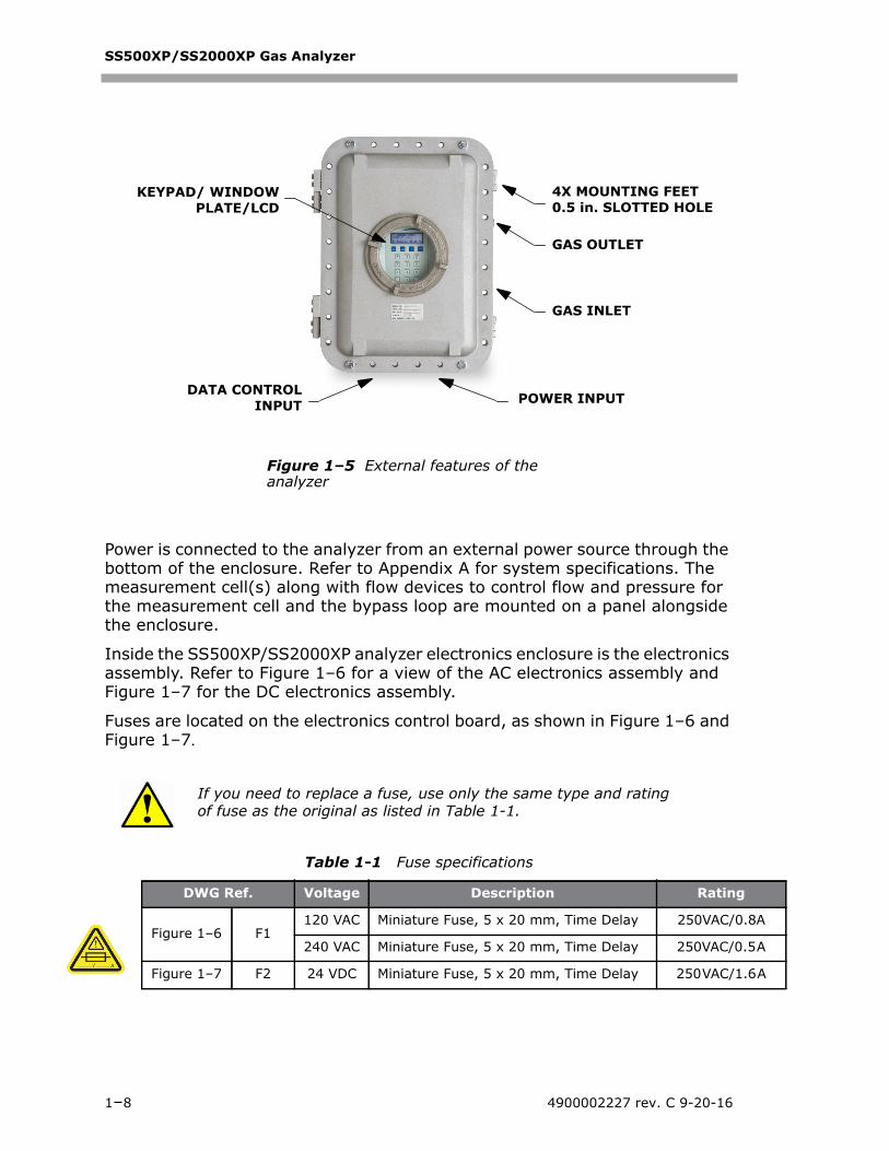
Power is connected to the analyzer from an external power source through the bottom of the enclosure. Refer to Appendix A for system specifications. The measurement cell(s) along with flow devices to control flow and pressure for the measurement cell and the bypass loop are mounted on a panel alongside the enclosure.
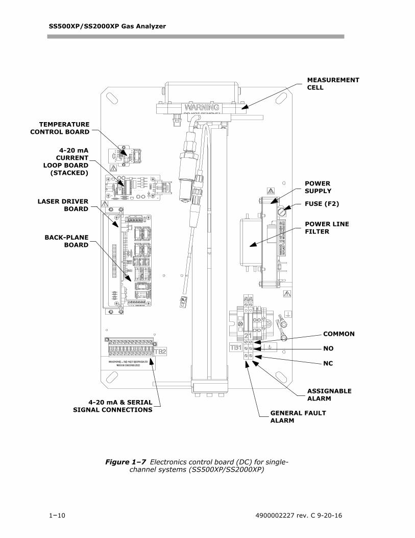
Inside the SS500XP/SS2000XP analyzer electronics enclosure is the electronics assembly. Refer to Figure 1–6 for a view of the AC electronics assembly and Figure 1–7 for the DC electronics assembly.
Fuses are located on the electronics control board, as shown in Figure 1–6 and Figure 1–7.
If you need to replace a fuse, use only the same type and rating of fuse as the original as listed in Table 1-1.
Table 1-1 Fuse specifications
DWG Ref. Voltage Description Rating
Figure 1–6 F1120 VAC Miniature Fuse, 5 x 20 mm, Time Delay 250VAC/0.
240 VAC Miniature Fuse, 5 x 20 mm, Time Delay 250VAC/0.
Figure 1–7 F2 24 VDC Miniature Fuse, 5 x 20 mm, Time Delay 250 VAC/1.
Figure 1–5 External features of the analyzer
KEYPAD/ WINDOWPLATE/LCD
4X MOUNTING FEET0.5 in. SLOTTED HOLE
DATA CONTROLINPUT POWER INPUT
GAS OUTLET
GAS INLET
1–8 4900002227 rev. C 9-20-16

Introduction
TECON
N
L
T
Figure 1–6 Electronics control panel (AC) for single-channel systems (SS500XP/SS2000XP)
MPERATURETROL BOARD
POWERSUPPLY
FUSE (F1)
ASSIGNABLEALARM
GENERAL FAULT ALARM
NO
COMMO
NC
4-20 mACURRENT
LOOP BOARD(STACKED)
BACK-PLANEBOARD
4-20 mA & SERIALSIGNAL CONNECTIONS
ASER DRIVERBOARD
MEASUREMENCELL
POWER LINEFILTER
Hardware Installation and Maintenance Manual 1–9
SS500XP/SS2000XP Gas Analyzer
N
NT
TCON
LA
Figure 1–7 Electronics control board (DC) for single-channel systems (SS500XP/SS2000XP)
ASSIGNABLEALARM
GENERAL FAULT ALARM
NO
COMMO
NC
4-20 mACURRENT
LOOP BOARD(STACKED)
4-20 mA & SERIALSIGNAL CONNECTIONS
MEASUREMECELL
POWERSUPPLY
POWER LINEFILTER
FUSE (F2)
EMPERATURETROL BOARD
SER DRIVERBOARD
BACK-PLANEBOARD
1–10 4900002227 rev. C 9-20-16
2 - INSTALLATION
This section describes the processes used to initially install and configure your SS500XP or SS2000XP. Once the analyzer arrives, you should take a few minutes to examine the contents before installing the unit. This section discusses:
• Unpacking and inspecting the analyzer
• Getting familiar with analyzer
• Installing the analyzer
What Should be Included in the Shipping BoxThe contents of the crate should include:
• The SpectraSensors SS500XP or SS2000XP analyzer
• CDs; Operator’s Manual and other manuals or documents as necessary
• One external serial cable(s) to connect the analyzer to a computer
• Additional accessories or options as ordered
If any of these contents are missing, contact “Customer Service” on page B-19.
Inspecting the Analyzer Unpack and place the unit on a flat surface. Carefully inspect all enclosures for dents, dings, or general damage. Inspect the inlet and outlet connections for damage, such as bent tubing. Report any damage to the carrier.
Installing the AnalyzerInstalling the analyzer is relatively easy requiring only a few steps that, when carefully followed, will ensure proper mounting and connection. This section includes:
• Hardware and Tools for Installation
• Mounting the Analyzer
• Connecting Electrical Power to the Analyzer
• Connecting the Output Signals
• Connecting the Gas Lines
Avoid jolting the instrument by dropping it or banging it against a hard surface. Do not attempt to pick up the instrument using the sample cell. Either action may disturb the optical alignment.
Hardware Installation and Maintenance Manual 2–1

SS500XP/SS2000XP Gas Analyzer
Hardware and Tools for Installation Depending on the particular model, the configuration of accessories and options ordered, you may need the following hardware and tools to complete the installation process.
Hardware• Membrane separator filter (if not included) *
• Pressure regulator (if not included) *
• Stainless steel tubing (SpectraSensors recommends using 1/4” O.D. x0.035” wall thickness, seamless stainless steel tubing)
• 1/2” conduit hubs
• Conduit (rigid)
• Source of plant nitrogen gas (4 SCFH) for purge unit(s), if applicable
• 1/2” or 3/8-16” Unistrut (or equivalent) bolts and spring nuts
• 3/8” x 1-1/2” machine screws and nuts (for non-Unistrut installation)
• 3/4” or 1/2” EYS (or equivalent) seals
• 1/4” Swagelok 400-1-4 (or equivalent) connectors
* If your system comes equipped with a sample conditioning system, refer to the Sample Conditioning System (SCS) manual for more information.
Tools• Hand drill and bits
• Tape measure
• Level
• Pencil
• Socket wrench set
• Screw driver
• Crescent wrench
• 9/16” open-end wrench
Lifting/carrying the analyzerDue to the analyzer’s size and weight (103 lbs., or 48.6 Kg.), SpectraSensors recommends the use of a forklift, pallet jack, etc. to lift and/or move the analyzer. Before removing the analyzer from the crate, move the crate as close as possible to the final location.
If the analyzer is to be lifted by hand, designate multiple individuals to lift by the mounting brackets, and distribute the weight among personnel to avoid injury.
Refer to Appendix A for drawings and specifications of the analyzer.
2–2 4900002227 rev. C 9-20-16

Installation
Mounting the AnalyzerThe SS500XP/SS2000XP Gas Analyzer analyzer is manufactured for wall or Unistrut (or equivalent) metal framing installations. Refer to the layout diagrams in Appendix A for specifications.
To mount the analyzer:1. Select a suitable location to mount the analyzer. Choose a shaded area
or use an optional analyzer hood (or equivalent) to minimize sun exposure.
2. Locate the mounting holes on your unit. Refer to Figure A–1 on page A–3.
3. For wall installations, mark the centers of the holes in the mounting brackets to the mounting surface.
4. Drill the appropriate size holes for the bolts you are using (SpectraSensors recommends 2” bolts at a minimum).
5. Hold the analyzer in place and fasten with the top screws.
6. Repeat for the bottom mounting holes.
Once all four screws are tightened the analyzer should be very secure and ready for the electrical connections.
Connecting Electrical Power to the AnalyzerThe analyzer will be configured for 100-240 VAC @ 50/60 Hz single phase input or optionally 18-24 VDC input. Check the manufacturing data label or the terminal block labels to determine the power input requirements. All work must be
When mounting the analyzer, be sure not to position the instrument so that it is difficult to operate adjacent devices. Allow 3 feet (1 m) of room in front of the analyzer and any switches.
It is critical to mount the analyzer so that the inlet and outlet lines reach the inlet and outlet connections on the chassis while still maintaining flexibility so that the sample lines are not under excessive stress.
SpectraSensors analyzers are designed for operation within the specified ambient temperature range of –4 °F to 122 °F (–20 °C to 50 °C). Intense sun exposure in some areas may cause the analyzer temperature to exceed the maximum.
Hardware Installation and Maintenance Manual 2–3

SS500XP/SS2000XP Gas Analyzer
performed by personnel qualified in electrical conduit installation. Conduit seals should be used where appropriate in compliance with local regulations.
Depending on the analyzer configuration, the electrical wiring can typically be connected to the analyzer through a conduit hub located at the bottom right or left of the electronics enclosure.
To connect electrical power to the analyzer:1. Open the electronics enclosure door. Take care not to disturb the
electrical assembly inside.
2. Run conduit from the power distribution panel to the tapped hole at the bottom of the analyzer enclosure. Refer to Figure A–2 on page A–4.
3. For AC systems, pull ground, neutral and hot wires (#14 AWG minimum) into the electronics enclosure.
For DC systems, pull ground, plus and minus wires.
Hazardous voltage and risk of electric shock. Turn off and lock out system power before opening the electronics enclosure and making any connections.
Hazardous voltage and risk of electric shock. Careful consideration should be taken when grounding. Properly ground the unit by connecting ground leads to the grounding studs provided throughout the system that are labeled with the ground symbol .
Hazardous voltage and risk of electric shock. Failure to properly ground the analyzer may create a high-voltage shock hazard.
Conduit seals should be used where appropriate in compliance with local regulations.
Because the breaker in the power distribution panel or switch will be the primary means of disconnecting the power from the analyzer, the power distribution panel should be located in close proximity to the equipment and within easy reach of the operator.
An approved switch or circuit breaker rated for 15 amps should be used and clearly marked as the disconnecting device for the analyzer.
2–4 4900002227 rev. C 9-20-16

Installation
4. Strip back the jacket and/or insulation of the wires just enough to connect to the power terminal block.
5. For AC systems, attach the neutral and hot wires to the power terminal block by connecting the neutral wire to the terminal marked “NEU” and the hot wire to the terminal marked “LINE” as shown in Figure 2–1.
For DC systems, connect the minus wire to the terminal marked “” and the positive wire to the terminal marked “+” as shown in Figure 2–1.
6. Connect the ground wire to the ground terminal marked .
7. Close and tighten the electronics enclosure door.
Connecting the Output SignalsThe 4-20 mA current loop and serial output(s) are supplied from the mating terminal block (TB2) located inside the analyzer electronics enclosure as shown in Figure 1–6 or Figure 1–7. By default, the 4-20 mA current loop output is factory set to source current.
NEU LINE
AC TERMINAL BLOCK
_ +
DC TERMINAL BLOCK
Figure 2–1 AC and DC connection terminal blocks in electronics enclosure
Hardware Installation and Maintenance Manual 2–5
dmyers
Rectangle
dmyers
Rectangle

SS500XP/SS2000XP Gas Analyzer
Connections can be made with customer-supplied cables for the current loop(s) and for the serial connection(s). Consult the wiring diagrams in Appendix A.
To connect the output signals:1. Disconnect power to the analyzer and open the electronics enclosure
cover. Take care not to disturb the electrical assembly inside.
2. Run conduit from the signal/alarm receiving station to the conduit hub on the electronics enclosure labeled for signal connections.
3. Pull the customer-supplied cable(s) for the current loop(s), digital output relays, and the external serial cable(s) through the conduit into the electronics enclosure.
4. Strip back the jacket and insulation of the current loop, digital output relays and serial cables just enough to connect to the mating terminal block (TB2), shown in Figure 2–2. The mating terminal block can be pulled up and removed from its base to make the cable connection process easier.
5. Connect the 4-20 mA current loop signal wires to the appropriate terminals, as indicated in Table 2–1.
6. Connect the serial cable wires to the appropriate terminals according to Table 2–1. For reference, Table 2–1 also shows the corresponding pin numbers for configuring a nine-pin Sub-D connector for connection to a computer serial port.
The 4-20 mA current loop output is factory set to source current. To change the 4-20 mA current loop output from source to sink, see “To change the 4-20 mA board from source to sink” on page 2-8.
Hazardous voltage and risk of electric shock. Turn off and lock out system power before opening the electronics enclosure and making any connections.
Conduit seals should be used where appropriate in compliance with local regulations.
The external serial cable included in the shipping container is provided for troubleshooting purposes and may not be the correct length for permanent installation.
2–6 4900002227 rev. C 9-20-16

Installation
7. Connect the digital output relays according to the call-outs shown in Figure 1–6 and Figure 1–7.
8. Re-insert the mating terminal block into its base and verify that each connection is secure.
9. Close and tighten the electronics enclosure cover.
10. To complete the connections, connect the other end of the current loop wires to a current loop receiver and each external serial cable to a serial port on your computer.
Table 2–1 Output signal connections
Terminal Description D-Conn Color
1 Ch. A Serial RX Pin-3 Black
2 Ch. A Serial TX Pin-2 Red
3 COM Serial Ground Pin-5 Shield
4 1 N/C
5 1 N/C
6 Ch. A Current Loop +
7 Ch. A Current Loop -
8 2 Ch. A Current Loop +
9 2 Ch. A Current Loop -
10 N/C
11 N/C
12 N/C
1. The description “N/C” indicates no connection.2. Performs the same function as terminal 6/7.
Figure 2–2 Mating terminal block (TB2) in electronics enclosure for connecting signal cables
TB212 11 10 9 8 7 6 5 4 3 2 1
Hardware Installation and Maintenance Manual 2–7
SS500XP/SS2000XP Gas Analyzer
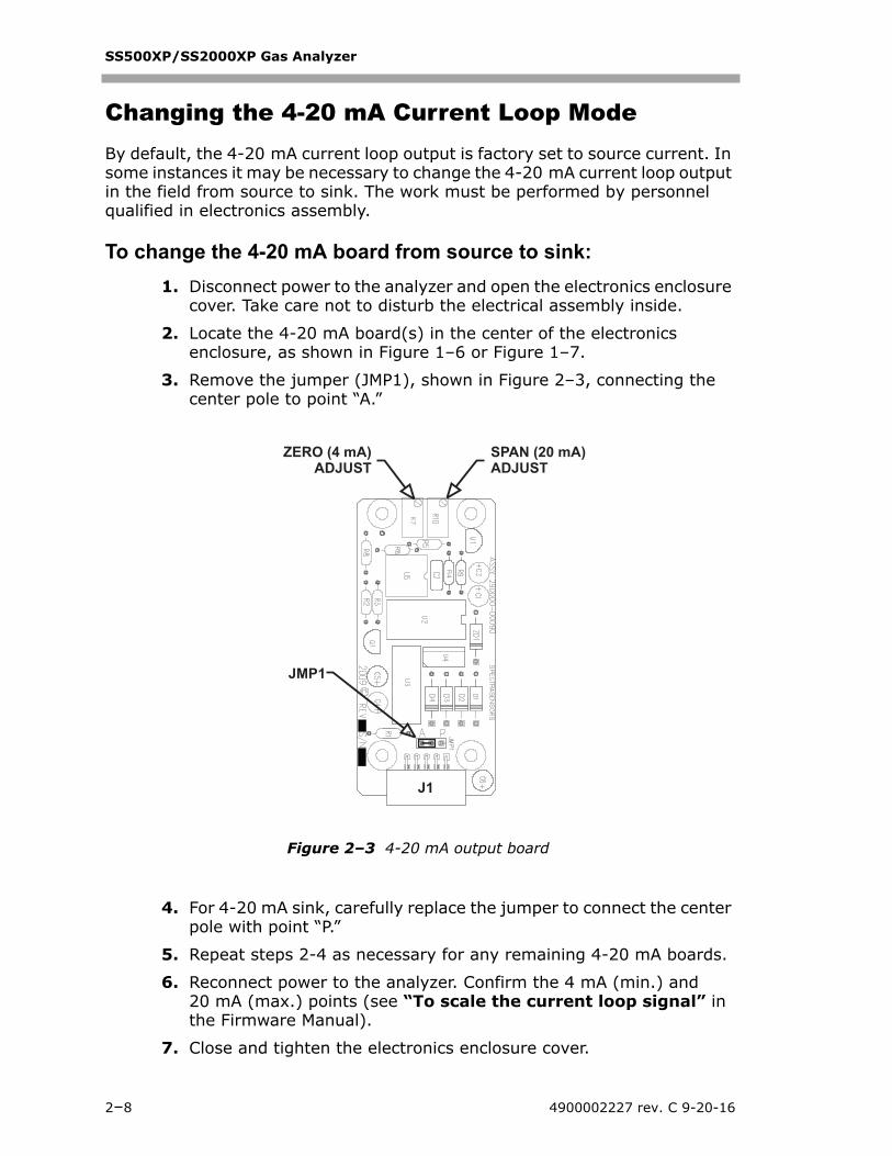
Changing the 4-20 mA Current Loop Mode
By default, the 4-20 mA current loop output is factory set to source current. In some instances it may be necessary to change the 4-20 mA current loop output in the field from source to sink. The work must be performed by personnel qualified in electronics assembly.
To change the 4-20 mA board from source to sink:1. Disconnect power to the analyzer and open the electronics enclosure
cover. Take care not to disturb the electrical assembly inside.
2. Locate the 4-20 mA board(s) in the center of the electronics enclosure, as shown in Figure 1–6 or Figure 1–7.
3. Remove the jumper (JMP1), shown in Figure 2–3, connecting the center pole to point “A.”
4. For 4-20 mA sink, carefully replace the jumper to connect the center pole with point “P.”
5. Repeat steps 2-4 as necessary for any remaining 4-20 mA boards.
6. Reconnect power to the analyzer. Confirm the 4 mA (min.) and 20 mA (max.) points (see “To scale the current loop signal” in the Firmware Manual).
7. Close and tighten the electronics enclosure cover.
ZERO (4 mA)ADJUST
SPAN (20 mA)ADJUST
JMP1
J1
Figure 2–3 4-20 mA output board
2–8 4900002227 rev. C 9-20-16
Installation
Connecting the Gas LinesOnce you have verified that the analyzer is properly wired, you are ready to connect the sample supply, sample return, and sample bypass (if applicable). Consult the Sample Conditioning System (SCS) manual for guidance. All work must be performed by technicians qualified in instrument tubing.
Application of Conduit Lubricant To ensure proper installation, SpectraSensors recommends using STL8 screw thread lubricant or equivalent on all conduit screw thread and its tapped opening.
STL8 Screw Thread Lubricant is a lithium based, anti-galling substance with excellent adhesion that maintains rain-tightness and grounding continuity between conduit fittings. This lubricant has proven very effective between parts made of dissimilar metals, and is stable in temperatures from -20 F to +300 F.
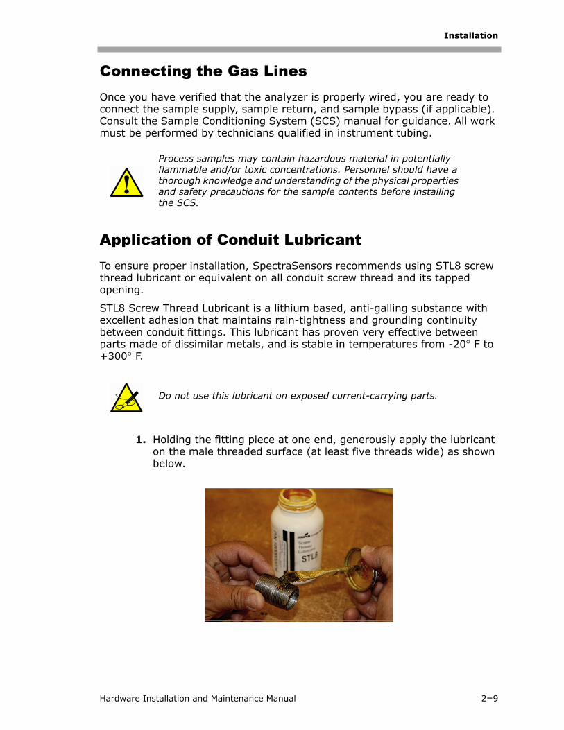
1. Holding the fitting piece at one end, generously apply the lubricant on the male threaded surface (at least five threads wide) as shown below.
Process samples may contain hazardous material in potentially flammable and/or toxic concentrations. Personnel should have a thorough knowledge and understanding of the physical properties and safety precautions for the sample contents before installing the SCS.
Do not use this lubricant on exposed current-carrying parts.
Hardware Installation and Maintenance Manual 2–9
SS500XP/SS2000XP Gas Analyzer
2. Screw the female pipe thread onto the male fitting until the lubricated threads are engaged.
Eyes: May cause minor irritation.
Skin: May cause minor irritation.
Ingestion: Relatively non-toxic. Ingestion may result in a laxative effect. Ingestion of substantial quantities may cause lithium toxicity.
2–10 4900002227 rev. C 9-20-16

Appendix A: Specifications
Table A–1 SS500XP H2O analyzer specifications
PerformanceTypical Measurement Ranges 1
1. Consult factory for alternative ranges.
2–20 lbs/MMscf (40–422 ppmv)2-50 lbs/MMscf (40-1055 ppmv)2-100 lbs/MMscf (40-2110 ppmv)
Application DataEnvironmental Temperature Range -4 to 122°F (-20 to 50°C)
15 to 140°F (-10 to 60°C) - Optional
Environmental Relative Humidity 80% for temperatures up to 31°C MAX
Altitude Up to 2000 m
Maximum Cell Pressure 70kPaG (10 PSIG)
Sample Cell Pressure Range 700-1400 mbara - Standard700-1700 mbara - Optional
Sample Flow Rate 1–2 scfh (0.5–1.0 LPM) typical
Recommended Validation Bureau of Mines chilled mirror, portable TDL or binary gas with methane background
Electrical & CommunicationsInput Voltages 2
2. Supply voltage not to exceed 10% of nominal. Transient over-voltages according to Overvoltage Category II.
100–240 VAC, 50/60 Hz (single phase only)18–24 VDC - Optional
Contact Rating(Inductive Load)
250V, 3A N.O. contact, 1.5A N.C. contact24V, 1A N.O. and N.C. contact
Communication Analog: (2) 4-20 mA Isolated, 1200 ohms @ 24 VDC max loadSerial: RS-232CProtocol: Modbus Gould RTU, Daniel RTU or ASCII
Digital Output (2); General Fault and Concentration/Assignable Alarm
LCD Display Concentration, cell pressure, temperature alarms & diagnostics
Physical SpecificationsSize 17.27" H x 14.59" W x 9.94" D
(565 mm H x 413 mm W x 252 mm D)
Weight Approx. 103 lbs (46.8 Kg)
Sample Cell Construction 316L Series Polished Stainless Steel
Area ClassificationCertifications CSA Class I, Division 1 Groups B, C and D;
T4; -20°C ≤ Tamb ≤ +50°C, Enclosure Type 4
Hardware Installation and Maintenance Manual A–1
SS500XP/SS2000XP Gas Analyzer
A–2 4900002227 rev. C 9-20-16
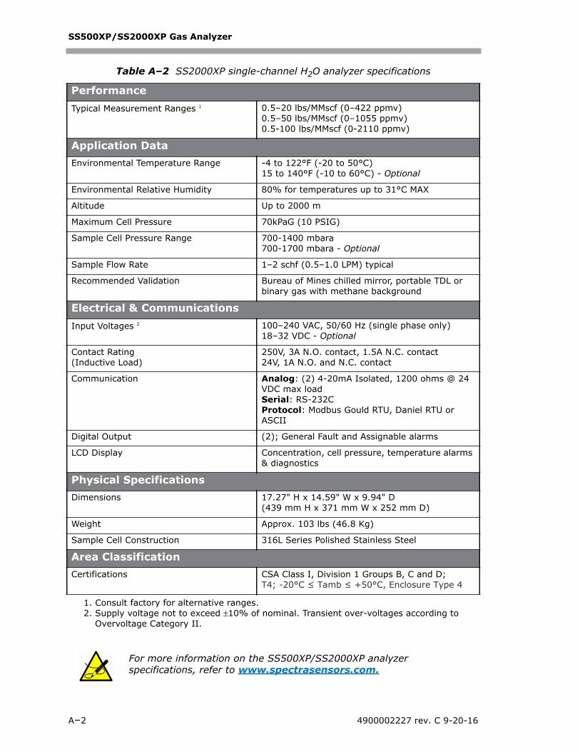
Table A–2 SS2000XP single-channel H2O analyzer specifications
PerformanceTypical Measurement Ranges 1 0.5–20 lbs/MMscf (0–422 ppmv)
0.5–50 lbs/MMscf (0–1055 ppmv)0.5-100 lbs/MMscf (0-2110 ppmv)
Application DataEnvironmental Temperature Range -4 to 122°F (-20 to 50°C)
15 to 140°F (-10 to 60°C) - Optional
Environmental Relative Humidity 80% for temperatures up to 31°C MAX
Altitude Up to 2000 m
Maximum Cell Pressure 70kPaG (10 PSIG)
Sample Cell Pressure Range 700-1400 mbara700-1700 mbara - Optional
Sample Flow Rate 1–2 schf (0.5–1.0 LPM) typical
Recommended Validation Bureau of Mines chilled mirror, portable TDL or binary gas with methane background
Electrical & CommunicationsInput Voltages 2 100–240 VAC, 50/60 Hz (single phase only)
18–32 VDC - Optional
Contact Rating (Inductive Load)
250V, 3A N.O. contact, 1.5A N.C. contact24V, 1A N.O. and N.C. contact
Communication Analog: (2) 4-20mA Isolated, 1200 ohms @ 24 VDC max loadSerial: RS-232CProtocol: Modbus Gould RTU, Daniel RTU or ASCII
Digital Output (2); General Fault and Assignable alarms
LCD Display Concentration, cell pressure, temperature alarms & diagnostics
Physical SpecificationsDimensions 17.27" H x 14.59" W x 9.94" D
(439 mm H x 371 mm W x 252 mm D)
Weight Approx. 103 lbs (46.8 Kg)
Sample Cell Construction 316L Series Polished Stainless Steel
Area ClassificationCertifications CSA Class I, Division 1 Groups B, C and D;
T4; -20°C ≤ Tamb ≤ +50°C, Enclosure Type 4
1. Consult factory for alternative ranges.2. Supply voltage not to exceed 10% of nominal. Transient over-voltages according to
Overvoltage Category II.
For more information on the SS500XP/SS2000XP analyzer specifications, refer to www.spectrasensors.com.

Specifications
Figure A–1 SS500XP/SS2000XP outline and mounting dimensions
MOUNTINGBRACKETS
Hardware Installation and Maintenance Manual A–3

SS500XP/SS2000XP Gas Analyzer
4.50
PWR INPUT3/4-14 FNPT
DATA/CONTROLS3/4-14 FNPT
7.50
4.56
4X .75
Figure A–2 SS500XP/SS2000XP bottom view - power and data controls input
A–4 4900002227 rev. C 9-20-16
Specifications
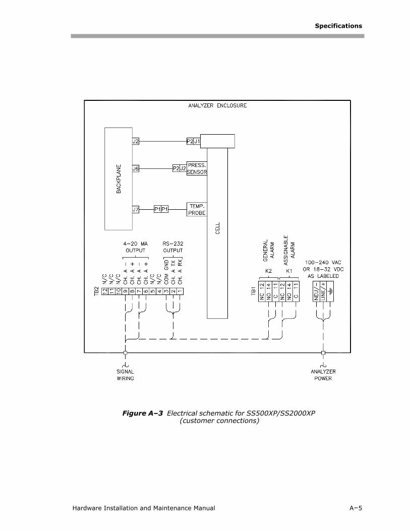
Figure A–3 Electrical schematic for SS500XP/SS2000XP (customer connections)
Hardware Installation and Maintenance Manual A–5

H2 O
or CO
2
A–6
4900002227 rev. C 9-20-16
+-
W1
E3
E1 E2
09 (W8)
GRN/YEL
(01902-16100)
W10)
(3100002151)
(GND)
BLU
POWER
P2
BLU
W2(V+ IN)
(2900000180)
BR
N
J1
24V
LINE FILTER
(A7)
GND
(A6)
GR
N
SUPPLY
BR
N
XP/SS2000XP)
HIG
HA
LAR
M C
H A
GE
N. F
AU
LTA
LAR
M, C
H A
2300000030
J13
(A8)
SUPPLY ASSY
(W2)
0220311000
YE
L
P1
P1
P1
J2P2
EAE-TDL
E2A2
GND
0250217201
(A7)
(3100002151)
0190216500
GR
N
J1
N L
(A6)
BLU
BR
N
E1
01902-172
P1
BLU
LINE FILTER
120 VAC
6000002242 (W11)
6000002243 (W12)
0190217203 (
AC/DC
BACK PLANE
2300000030
(W7)
N L
J1
T
TEMP A
OPT HEAD A
PRES A
P2
P2
P1
GR
Y
WH
T
SAMPLE CELL
(A5)
BR
N
PRES.
P1
(W6) 6000002222
YEL
WHT
GRY
(W5)
(W4)
(W3)
+5V
(A2)
(A1)
+12V
GN
D
J6
(A4)
(A3)
DBA C
K1K2
NOCOM NC
A2A1
NOCOM NC
TEMP CTRL A
P2
29000-00090
CRNT LOOP B
J7J2
J2
P1
J8
P2
P1J5 J1
J1
P2P1
P2P1
J10
J15
J9J3
J4
J1 0190213000
(W9)
J1 29000-00090
CRNT LOOP A
A1
J3
J14
J1
J11
CHAN A
(W1) 6000002072
PWR
(W2) 02101-17206
Figure A–4 Interconnect diagram for single-channel system (SS500

Specifications
Spare PartsBelow is a list of spare parts for the SS500XP/SS2000XP analyzers with recommended quantities for 2 years of operation. Due to a policy of continuous improvement, parts and part numbers may change without notice. Not all parts listed are included on every analyzer. When ordering, please specify the system serial number to ensure that the correct parts are identified.
Table A–3 Replacement parts for SS500XP/SS2000XP analyzers
Part Number Description 2 Yr. Qty.
Analyzer
0190217106 RS-232C Serial Data Cable 1
8000002199 Temperature Control Board 1
1. Contact SpectraSensors service department before attempting replacement. Replac-ing this component without technical support could cause damage to other compo-nents.
-
2900000180 Power Supply, 24 VDC 1 -
8000002692 Power Supply, 100-240 VAC 50/60 Hz, CSA 1 -
0190230011 Keypad Assembly 1 -
8000002584 Display Assembly -
0219900005 Kit, O-rings Viton, 2-Pass Cell 1 1
0219900011 Kit, Fuse, AC, DC 1
0900002146 Stainless steel mirror replacement -
Pressure Sensor
5500002016 Pressure Sensor, 30 PSIA, 5V, 1/8” MNPT DIN4365 NACE -
6000002242 Cable, Pres Sens, 10.5” 1 -
General Items
0219900007 Cleaning Kit, Optical Cell (Domestic U.S./Canada) 1 1
0219900017 Cleaning Kit, Optical Cell, No Chemicals (International) 1 1
4900002227 SS500XP/SS2000XP Hardware Installation and Mainte-nance Manual, additional copies
-
4900002225 Firmware v2.51 Operator’s Manual, additional copies -
Hardware Installation and Maintenance Manual A–7

SS500XP/SS2000XP Gas Analyzer
THIS PAGE INTENTIONALLY LEFT BLANK
A–8 4900002227 rev. C 9-20-16

Appendix B: Troubleshooting
This section presents recommendations and solutions to common problems, such as "Gas Leaks", "Contamination", "Excessive Sampling Gas Temperatures and Pressures", and "Electrical Noise". If your analyzer does not appear to be hampered by one of these related problems, direct questions to your "Service Contact".
Potential Risks Affecting PersonnelThis section addresses the appropriate actions to undertake when faced with hazardous situations during or before service of the analyzer. It is not possible to list all potential hazards within this document. The user is responsible for identifying and mitigating any potential hazards present when servicing the analyzer.
Mitigating risksRefer to the instructions for each situation listed below to mitigate associated risks.
Exposure to process gases
1. Shut off the process gas to the analyzer before any service that would require opening a part of the sample plumbing.
2. Purge the system with nitrogen.
3. Shut off the nitrogen purge before opening any part of the sample system.
Exposure to toxic gas (H2S)
Follow the procedure below if there has been any suspected leak from the sample system and accumulated SCS enclosure. For analyzers with higher levels of H2S, a safety purge kit is installed.
1. Purge the SCS enclosure to remove any potentially toxic gas.
2. Test the H2S levels of the SCS enclosure using the port from the safety purge kit to ensure the purge has cleared any toxic gas.
Technicians are expected to follow all safety protocols established by the customer that are necessary for servicing the analyzer. This may include, but is not limited to, lockout/tag-out procedures, toxic gas monitoring protocols, PPE requirements, hot work permits and other precautions that address safety concerns related to performing service on process equipment located in hazardous areas.
Hardware Installation and Maintenance Manual B–1

SS500XP/SS2000XP Gas Analyzer
3. If no gas leak is detected, open the SCS enclosure door.
Electrocution hazard
1. Shut off power at the main disconnect external to the analyzer.
2. Open enclosure door.
If service must be performed with power engaged (gain adjustment, etc.):
1. Note any live electrical components and avoid any contact with them.
2. Only use tools with a safety rating for protection against accidental contact with voltage up to 1000V (IEC 900, ASTF-F1505-04, VDE 0682/201).
Explosion hazard
Any work in a hazardous area must be carefully controlled to avoid creating any possible ignition sources (e.g., heat, arcing, sparking, etc.). All tools must be appropriate for the area and hazards present. Electrical connections must not be made or broken with power on (to avoid arcing).
Gas LeaksProbably the most common cause of erroneous measurements is outside air leaking into the sample supply line. SpectraSensors recommends periodically testing the supply lines, especially if the analyzer has been relocated, replaced or returned to the factory for service, and the sample lines have been reconnected.
Follow all safety protocols governing toxic gases and potential leaks.
Complete this action before performing any service that requires working near the main input power or disconnecting any wiring or other electrical components.
Do not use plastic tubing of any kind for sample lines. Plastic tubing is permeable to moisture and other substances which can contaminate the sample stream. SpectraSensors recommends using 1/4” O.D x0.035” wall thickness, seamless stainless steel tubing.
B–2 4900002227 rev. C 9-20-16
Troubleshooting
ContaminationContamination and long exposure to high humidity are valid reasons for periodically cleaning the gas sampling lines. Contamination in the gas sampling lines can potentially find its way to the sample cell and deposit on the optics or interfere with the measurement in some other way. Although the analyzer is designed to withstand some contamination, it is recommended to always keep the sampling lines as contamination free as possible.
To keep the sampling lines clean:1. Make sure that a membrane separator filter (included with most
systems) is installed ahead of the analyzer and operating normally. Replace the membrane if necessary. If liquid enters the cell and accumulates on the internal optics, a Power Fail Error will result.
2. If mirror contamination is suspected, see “Cleaning the Mirrors” on page B-4.
3. Turn off the sample valve at the tap in accordance with site lock-out, tag-out rules.
4. Disconnect the gas sampling line from the supply port of the analyzer.
5. Wash the sampling line with alcohol or acetone and blow dry with mild pressure from a dry air or nitrogen source.
6. Once the sampling line is completely free of solvent, reconnect the gas sampling line to the supply port of the analyzer.
7. Check all connections for gas leaks. SpectraSensors recommends using a liquid leak detector.
Excessive Sampling Gas Temperatures and PressuresThe embedded software is designed to produce accurate measurements only within the allowable cell operating range (see Appendix A). Pressures and temperatures outside these ranges will trigger a P/T Fail Error fault.
Process samples may contain hazardous material in potentially flammable and/or toxic concentrations. Personnel should have a thorough knowledge and understanding of the physical properties and safety precautions for the sample contents before operating the SCS.
If the pressure, temperature, or any other readings on the LCD appear suspect, they should be checked against the specifications (see Appendix A).
Hardware Installation and Maintenance Manual B–3

SS500XP/SS2000XP Gas Analyzer
Electrical NoiseHigh levels of electrical noise can interfere with laser operation and cause it to become unstable. Always connect the analyzer to a properly grounded power source.
Cleaning the MirrorsIf contamination makes its way into the cell and accumulates on the internal optics, a Power Fail Error will result. If mirror contamination is suspected, please consult with your factory sales representative before attempting to clean the mirrors. If advised to do so, use the following procedure.
Tools and Supplies• Lens cleaning cloth (Cole Parmer® EW-33677-00 TEXWIPE®
Alphawipe® Low-Particulate Clean Room Wipes or equivalent)
• Reagent-grade isopropanol (ColeParmer® EW-88361-80 or equivalent)
• Small drop dispenser bottle (Nalgene® 2414 FEP Drop Dispenser Bottle or equivalent)
• Acetone-impenetrable gloves (North NOR CE412W Nitrile Chemsoft™ CE Cleanroom Gloves or equivalent)
• Hemostat (Fisherbrand™ 13-812-24 Rochester-Pean Serrated Forceps)
• Bulb blower or dry compressed air/nitrogen
• Torque wrench
• Permanent marker
• Flashlight
Do not attempt to clean the cell mirror until you have consulted with your factory service representative and have been advised to do so.
The sample cell assembly contains a low-power, 10 mW MAX, CW Class 3b invisible laser with a wavelength between 700-3000 nm. Never open the sample cell flanges or the optical assembly unless the power is turned off.
Always handle the optical assembly by the edge of the mount. Never touch the coated surfaces of the mirror.
B–4 4900002227 rev. C 9-20-16
Troubleshooting
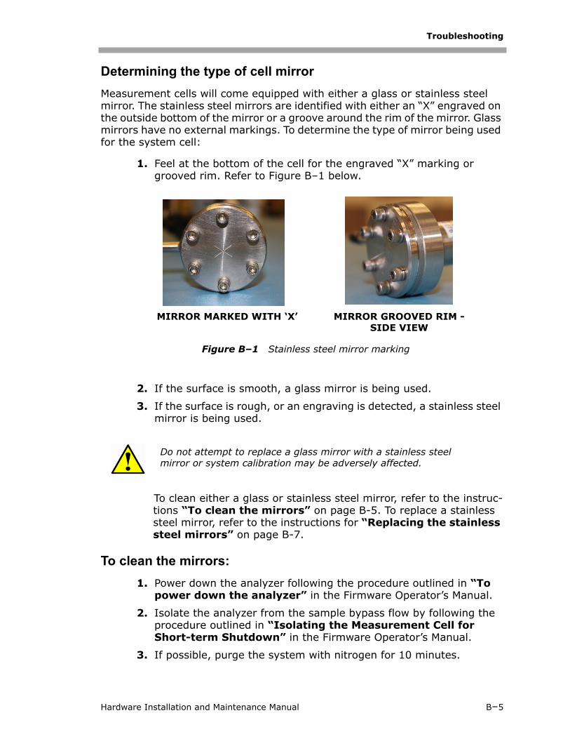
Determining the type of cell mirrorMeasurement cells will come equipped with either a glass or stainless steel mirror. The stainless steel mirrors are identified with either an “X” engraved on the outside bottom of the mirror or a groove around the rim of the mirror. Glass mirrors have no external markings. To determine the type of mirror being used for the system cell:
1. Feel at the bottom of the cell for the engraved “X” marking or grooved rim. Refer to Figure B–1 below.
2. If the surface is smooth, a glass mirror is being used.
3. If the surface is rough, or an engraving is detected, a stainless steel mirror is being used.
To clean either a glass or stainless steel mirror, refer to the instruc-tions “To clean the mirrors” on page B-5. To replace a stainless steel mirror, refer to the instructions for “Replacing the stainless steel mirrors” on page B-7.
To clean the mirrors:1. Power down the analyzer following the procedure outlined in “To
power down the analyzer” in the Firmware Operator’s Manual.
2. Isolate the analyzer from the sample bypass flow by following the procedure outlined in “Isolating the Measurement Cell for Short-term Shutdown” in the Firmware Operator’s Manual.
3. If possible, purge the system with nitrogen for 10 minutes.
Do not attempt to replace a glass mirror with a stainless steel mirror or system calibration may be adversely affected.
Figure B–1 Stainless steel mirror marking
MIRROR MARKED WITH ‘X’ MIRROR GROOVED RIM - SIDE VIEW
Hardware Installation and Maintenance Manual B–5
SS500XP/SS2000XP Gas Analyzer
4. Carefully mark the orientation of the mirror assembly on the cell body.
5. Gently remove the mirror assembly from the cell by removing the six socket-head cap screws and set on a clean, stable and flat surface
6. Look inside the sample cell at the top mirror using a flashlight to ensure that there is no contamination on the top mirror.
7. Remove dust and other large particles of debris using a bulb blower or dry compressed air/nitrogen. Pressurized gas duster products are not recommended as the propellant may deposit liquid droplets onto the optic surface.
8. Put on clean acetone-impenetrable gloves.
9. Double fold a clean sheet of lens cleaning cloth and clamp near and along the fold with the hemostats or fingers to form a “brush.”
10. Place a few drops of isopropanol onto the mirror and rotate the mirror to spread the liquid evenly across the mirror surface.
11. With gentle, uniform pressure, wipe the mirror from one edge to the other with the cleaning cloth only once and only in one direction to remove the contamination. Discard the cloth.
12. Repeat with a clean sheet of lens cleaning cloth to remove the streak left by the first wipe. Repeat, if necessary, until there is no visible contamination on the mirror.
13. Carefully replace the mirror assembly onto the cell in the same orientation as previously marked making sure the O-ring is properly seated.
14. Tighten the 6 socket-head cap screws evenly with a torque wrench to 13 in-lbs.
Careful marking of the mirror orientation is critical to restoring system performance upon reassembly after cleaning.
Due to its proximity to the optical head, SpectraSensors does not recommend cleaning the top mirror. If the top mirror is visibly contaminated, contact your factory service representative.
Never rub an optical surface, especially with dry tissues, as this can mar or scratch the coated surface.
B–6 4900002227 rev. C 9-20-16
Troubleshooting
Replacing the stainless steel mirrors:If your system has been configured with a stainless steel mirror and cleaning has not resolved the contamination issue, use the following instructions to replace the mirror.
1. Power down the analyzer following the procedure outlined in the section called “Powering Down the Analyzer” in the Firmware Operator’s Manual.
2. Isolate the analyzer from the sample bypass flow by shutting off the appropriate valve(s) and/or pressure regulator.
3. If possible, purge the measurement cell with nitrogen for 10 minutes.
4. Gently remove the mirror assembly from the cell by removing the socket-head cap screws and set on a clean, stable and flat surface.
5. Confirm need to replace mirror due to contamination. If yes, set mirror aside.
6. Put on clean acetone-impenetrable gloves.
7. Obtain the new stainless steel mirror. Refer to Figure B–2.
If stainless steel mirrors are replacing another version of mirror in the field, such as glass, the analyzer may need to be returned to the factory for re-calibration to ensure optimal cell function. Refer to “Packing” on page B-20.
All valves, regulators, switches, etc. should be operated in accordance with site lock-out/tag-out procedures.
Process samples may contain hazardous material in potentially flammable and/or toxic concentrations. Personnel should have a thorough knowledge and understanding of the physical properties and safety precautions for the sample contents before operating the SCS.
The sample cell assembly contains a low-power, 10 mW MAX, CW Class 3b invisible laser with a wavelength between 750-3000 nm. Never open the sample cell flanges or the optical assembly unless the power is turned off.
Always handle the optical assembly by the edge of the mount. Never touch the optical surfaces of the mirror.
Hardware Installation and Maintenance Manual B–7

SS500XP/SS2000XP Gas Analyzer
8. Check the O-ring.
a. If a new O-ring is needed, apply grease on fingertips and then to the new O-ring.
b. Place newly greased O-ring into the groove around the outside of the mirror taking care not to touch the mirror surface.
9. Carefully place the new stainless steel mirror onto the cell making sure the O-ring is properly seated.
10. Tighten the socket-head cap screws evenly with a torque wrench to 13 in-lbs.
Pressure Sensor ReplacementA pressure sensor may need to be replaced in the field as a result of one or more of the following conditions:
• Loss of pressure reading
• Incorrect pressure reading
• Pressure sensor not responding to pressure change
• Physical damage to the pressure sensor
Use the following information to replace a pressure sensor.
Tools and materials:• 9/16” wrench
• 7/8” wrench
• 9-64” Allen wrench
• Flat-head screwdriver
• Phillips-head screwdriver
• Metal pick
Figure B–2 Stainless steel mirror; mirror side up
B–8 4900002227 rev. C 9-20-16

Troubleshooting
• Military grade stainless steel PTFE tape (or equivalent)
• Dry nitrogen
• Isopropyl alcohol
To replace the pressure sensor:
1. Close the external flow of gas to the sample conditioning system (SCS) at the sample inlet.
2. Purge the system by connecting dry nitrogen to the sample inlet. Allow the SCS to purge for 5-10 minutes.
3. Close the nitrogen flow.
4. Power off the system. Refer to the Firmware Manual for this analyzer for “Powering down the analyzer”.
5. Open the door to the Analyzer. Refer to Figure B–3. In this view, the old model pressure sensor is pictured.
Alcohol can be hazardous. Follow all safety precautions when in use and thoroughly wash hands prior to eating.
Figure B–3 SS2000XP cabinet interior
CELL OUTLET
CELL INLET
MOUNTINGBRACKET
(behind cell)
OPTICAL HEADRIBBON CABLE
BACKPLANEBOARD
PRESSURESENSOR/ CABLE
MOUNTINGBRACKET
(behind cell)
Hardware Installation and Maintenance Manual B–9
SS500XP/SS2000XP Gas Analyzer
6. Remove the optical cable harness using a flat-head screwdriver.
7. Disconnect the cell inlet using a 9/16” wrench.
8. Disconnect the cell outlet using a 9/16” wrench.
9. Disconnect the thermistor cable at the circular connector.
10. Remove the pressure sensor cable from the circular connector inside the enclosure.
For new model pressure sensors with quick-disconnects, detach the pressure sensor cable from the pressure sensor at the connector using a Phillips-head screwdriver. Do not remove the black connector from the cable inside the enclosure.
11. Dismount the cell from the bracket by removing the four securing screws (two on top, two on the bottom) using a 9-64” Allen wrench.
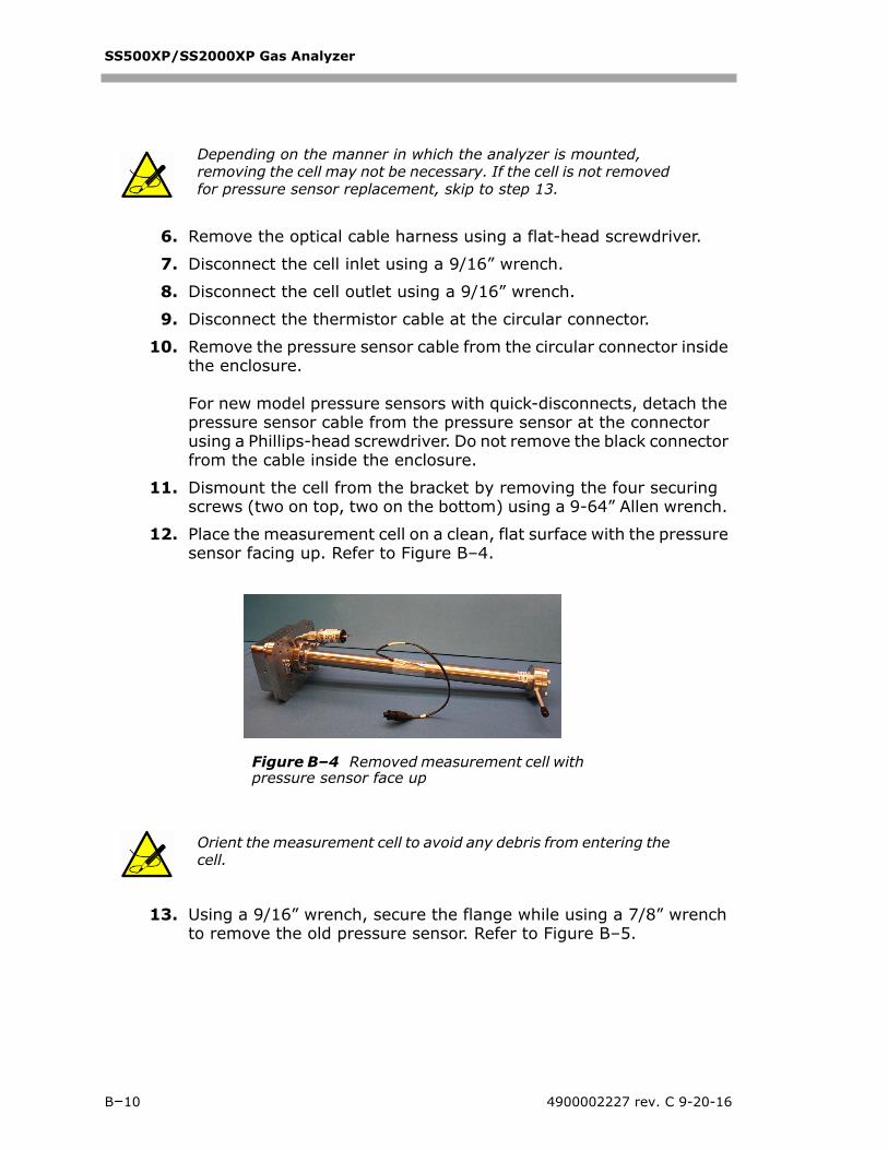
12. Place the measurement cell on a clean, flat surface with the pressure sensor facing up. Refer to Figure B–4.
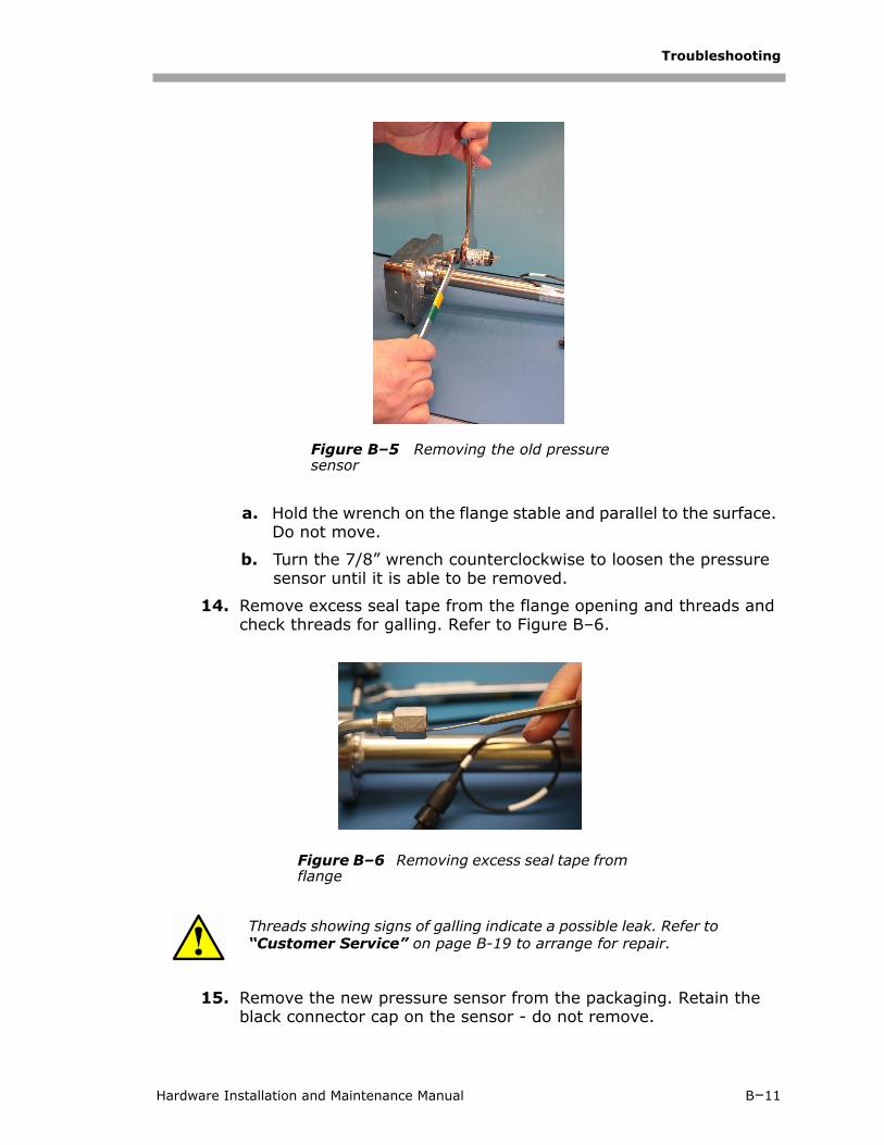
13. Using a 9/16” wrench, secure the flange while using a 7/8” wrench to remove the old pressure sensor. Refer to Figure B–5.
Depending on the manner in which the analyzer is mounted, removing the cell may not be necessary. If the cell is not removed for pressure sensor replacement, skip to step 13.
Orient the measurement cell to avoid any debris from entering the cell.
Figure B–4 Removed measurement cell with pressure sensor face up
B–10 4900002227 rev. C 9-20-16
Troubleshooting
a. Hold the wrench on the flange stable and parallel to the surface. Do not move.
b. Turn the 7/8” wrench counterclockwise to loosen the pressure sensor until it is able to be removed.
14. Remove excess seal tape from the flange opening and threads and check threads for galling. Refer to Figure B–6.
15. Remove the new pressure sensor from the packaging. Retain the black connector cap on the sensor - do not remove.
Threads showing signs of galling indicate a possible leak. Refer to “Customer Service” on page B-19 to arrange for repair.
Figure B–5 Removing the old pressure sensor
Figure B–6 Removing excess seal tape from flange
Hardware Installation and Maintenance Manual B–11

SS500XP/SS2000XP Gas Analyzer
16. Wrap stainless steel PTFE tape around the threads at the top of the pressure sensor, beginning from the base of the threads to the top, approximately three times taking care to avoid covering the top opening. Refer to Figure B–7.
17. Insert the new pressure sensor into the threaded flange keeping the sensor parallel to the surface for proper fitting.
18. Hand tighten the pressure sensor turning it counterclockwise into the flange until no longer moving freely. Refer to Figure B–8.
19. Using the 9/16” wrench to hold the flange in place, turn the sensor clockwise with a 7/8” wrench until tight. Two or three threads on the pressure sensor should still be visible.
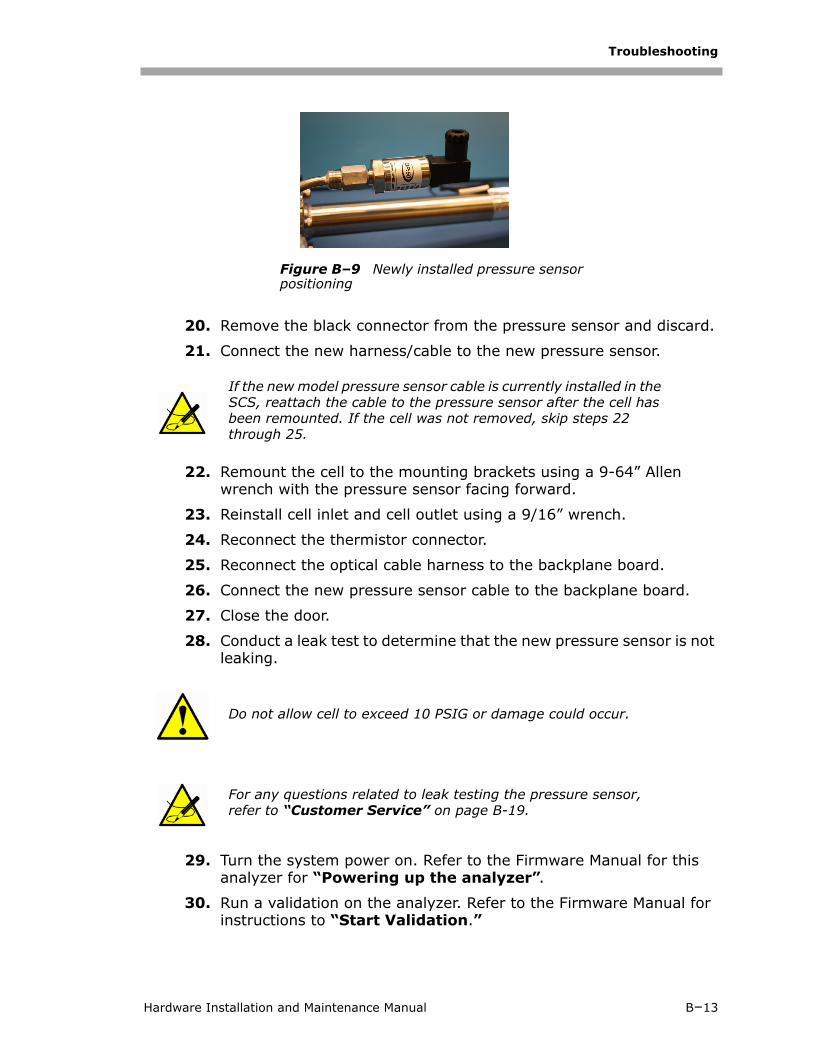
Make sure the black connector at the bottom of the pressure sensor is facing up from the measurement cell, or forward towards the enclosure door. Refer to Figure B–9.
Figure B–7 Replacing seal tape
Figure B–8 Replacing pressure sensor
B–12 4900002227 rev. C 9-20-16
Troubleshooting
20. Remove the black connector from the pressure sensor and discard.
21. Connect the new harness/cable to the new pressure sensor.
22. Remount the cell to the mounting brackets using a 9-64” Allen wrench with the pressure sensor facing forward.
23. Reinstall cell inlet and cell outlet using a 9/16” wrench.
24. Reconnect the thermistor connector.
25. Reconnect the optical cable harness to the backplane board.
26. Connect the new pressure sensor cable to the backplane board.
27. Close the door.
28. Conduct a leak test to determine that the new pressure sensor is not leaking.
29. Turn the system power on. Refer to the Firmware Manual for this analyzer for “Powering up the analyzer”.
30. Run a validation on the analyzer. Refer to the Firmware Manual for instructions to “Start Validation.”
If the new model pressure sensor cable is currently installed in the SCS, reattach the cable to the pressure sensor after the cell has been remounted. If the cell was not removed, skip steps 22 through 25.
Do not allow cell to exceed 10 PSIG or damage could occur.
For any questions related to leak testing the pressure sensor, refer to “Customer Service” on page B-19.
Figure B–9 Newly installed pressure sensor positioning
Hardware Installation and Maintenance Manual B–13

SS500XP/SS2000XP Gas Analyzer
a. If the system passes, the pressure sensor replacement is successful.
b. If the system does not pass, refer “Customer Service” on page B-19 for instruction.
Peak Tracking Reset ProcedureThe analyzer’s software is equipped with a peak tracking function that keeps the laser scan centered on the absorption peak. Under some circumstances, the peak tracking function can get lost and lock onto the wrong peak. If the difference between PkDf and PkD1 is more than 4, or Track Fail Error is displayed, the peak tracking function should be reset. Refer to the Firmware Manual for this analyzer for instruction.
Instrument ProblemsIf the instrument does not appear to be hampered by gas leaks, contamination, excessive sampling gas temperatures and pressures, or electrical noise, refer to Table B–1 before contacting your sales representative for service.
Table B–1 Potential instrument problems and solutions
Symptom Response
Non-Operation (at start up) Is the power connected to both the analyzer and power source? Is the switch on?
Non-Operation (after start up) Is the power source good? (100-250 VAC @ 50-60 Hz, 9-16 VDC, 18-32 VDC).
Check fuse(s). If bad, replace with equivalent amperage, slow-blow fuse.
Contact a factory sales representative for service information.
Power Fail Error Turn off the power to the unit and check the optical head cables for a loose connection. Do not disconnect or reconnect any optical head cables with the power connected.
Check the inlet and outlet tubes to see if they are under any stress. Remove the connections to the inlet and outlet tubes and see if the power goes up. The existing tubing may need to be replaced with stainless steel flexible tubing.
B–14 4900002227 rev. C 9-20-16

Troubleshooting
Table B-1 Potential instrument problems and solutions (Continued)
Symptom Response
Power Fail Error (Continued) Possible mirror contamination issue. Contact a factory sales representative for service information. If advised to do so, clean the mirrors by following the instructions under “To clean the mir-rors” on page B-5.
Possible alignment problem. Contact a factory sales representative for service information.
Capture diagnostic data and send the file to SpectraSensors (refer to “To read diagnostic data with Hyper-Terminal” in the Firmware Manual).
Verify Power Fail error. Refer to the Firmware Manual for instruction.
Null Fail Error Refer to the Firmware Manual to verify a Null Fail Error fault.
Move the jumper JMP1 on the HC12 main board next to the pre-pot.
Capture diagnostic data and send the file to SpectraSensors (refer to “To read diagnostic data with Hyper-Terminal” in the Firmware Manual).
Spectrum Fail Error Turn off the power to the unit and check the optical head cables for a loose connection. Do not disconnect or reconnect any optical head cables with the power connected.
Turn the analyzer off for 30 seconds and then turn it on again.
Reset the peak tracking.
Capture diagnostic data and send the file to SpectraSensors (refer to “To read diagnostic data with Hyper-Terminal” in the Firmware Manual).
Track Fail Error Refer to the Firmware Manual for instruction on system faults.
Reset the peak tracking.
Hardware Installation and Maintenance Manual B–15

SS500XP/SS2000XP Gas Analyzer
Table B-1 Potential instrument problems and solutions (Continued)
Symptom Response
P/T Fail Error Check that the actual pressure in the measurement cell is within specification (see Appendix A).
If the pressure reading is incorrect, check that the pressure/temperature cable is tight. Check the connector on the pressure sensor. Check the pres-sure connector on the backplane board.
Check that the actual temperature in the measurement cell is within specifi-cation (see Appendix A).
If the temperature reading is incorrect, check that the pressure/temperature cable is tight. Check the connector on the cell temperature sensor. Check the temperature connector on the back-plane board. (Note: A temperature reading greater than 302°F (150°C) indicates a short circuit on the tem-perature sensor leads; a reading of less than –40°F (–40°C) indicates an open circuit).
Front panel display is not lit and no characters appear
Check for correct voltage on terminal block input. Observe polarity on DC powered units.
Check for correct voltage after fuses.
Check for 5 VDC on red wires, 12 VDC on yellow wires, and 24 VDC on orange wires from power supply (black wires are ground).
Check connections on display commu-nication and power cables.
Strange characters appear on front panel display
Check connections on display commu-nication cable.
Reading seems to always be low by a fixed amount
Refer to the Firmware Manual for “Adjusting Analyzer Reading to Match Specific Standard(s)”.
Capture diagnostic data and send the file to SpectraSensors (refer to “To read diagnostic data with Hyper-Terminal” in the Firmware Manual).
B–16 4900002227 rev. C 9-20-16

Troubleshooting
Table B-1 Potential instrument problems and solutions (Continued)
Symptom Response
No reading on device connected to current loop
Make sure that connected device can accept a 4-20 mA signal. The analyzer is set to source current.
Make sure the device is connected to the correct terminals on the green con-nector (see Figure 2–2 on page 2–7).
Check the open circuit voltage (35-40 VDC) across the current loops ter-minals on the green connector (see Figure 2–2 on page 2–7).
Replace the current loop device with a milliampere meter and look for current between 4 mA and 20 mA. A voltmeter connected across a 249-ohm resistor can be used instead of the milliampere meter; it should read between 1 and 5 volts.
Reading seems to always be low by a fixed percentage
Refer to the Firmware Manual for “Adjusting Analyzer Reading to Match Specific Standard(s)”.
Reading seems to always be high by a fixed percentage
Refer to the Firmware Manual for “Adjusting Analyzer Reading to Match Specific Standard(s)”.
Capture diagnostic data and send the file to SpectraSensors (refer to “To read diagnostic data with Hyper-Terminal” in the Firmware Manual).
Reading seems to always be high by a fixed amount
Refer to the Firmware Manual for “Adjusting Analyzer Reading to Match Specific Standard(s)”.
Capture diagnostic data and send the file to SpectraSensors (refer to “To read diagnostic data with Hyper-Terminal” in the Firmware Manual).
Reading is erratic or seems incorrect Check for contamination in the sample system, especially if the readings are much higher than expected.
Capture diagnostic data and send the file to SpectraSensors (refer to “To read diagnostic data with Hyper-Terminal” in the Firmware Manual).
Hardware Installation and Maintenance Manual B–17

SS500XP/SS2000XP Gas Analyzer
Table B-1 Potential instrument problems and solutions (Continued)
Symptom Response
Reading goes to full scale If 4-20 mA Alarm Action is set to 1, look on display for a fault message (refer to the Firmware Manual for instruction on system faults and “To change parameters in Mode 2”).
Gas concentration is greater than or equal to full scale value.
Reading goes to “0” If 4-20 mA Alarm Action is set to 0, look on display for a fault message (refer to the Firmware Manual for instruction on system faults and “To change parameters in Mode 2”).
Gas concentration is equal to zero.
Serial output is providing no data Make sure the computer COM port is set for 19200 baud, 8 data bits, 1 stop bit, no parity, and no flow control.
Be sure no other programs are using the COM port selected.
Make sure the connections are good. Verify the correct pin connections with an ohmmeter.
Make sure to select the correct COM port into which the cable is plugged.
Serial output is displaying garbled data Make sure the computer COM port is set for correct baud, 8 data bits, 1 stop bit, no parity, and no flow control.
Be sure no other programs are using the COM port selected.
Make sure the connections are good. Verify the correct pin connections with an ohmmeter.
Make sure to select the correct COM port that the cable is plugged into.
Current loop is stuck at 4 mA or 20 mA On the current loop board, check the voltage between the end of resistor R1 closest to the jumper and ground. If the concentration reading is high, the voltage should be near 1 VDC. If the concentration reading is low, the volt-age should be near 4.7 VDC. If not, the problem is probably on the HC12 main board. Return to factory for service.
B–18 4900002227 rev. C 9-20-16

Troubleshooting
Service ContactIf the troubleshooting solutions do not resolve the problem, contact customer service. To return the unit for service or replacement, refer to "Service Repair Order".
Customer Service4333 W Sam Houston Pkwy N, Suite 100Houston, TX 77043-1223United States of America
For SpectraSensors North America Service:
Phone: 1-800-619-2861, and press 2 for Technical ServiceFax: 1-713-856-6623 E-mail: [email protected]: Service engineers are on duty Monday-Friday, 8:00 a.m. to 5:00 p.m. Central Time.
For SpectraSensors International Service, please contact the SpectraSensors distributor or the E+H Sales Center in your area, or contact:
Phone: +1-713-466-3172, and press 2 for Technical ServiceFax: +1-713-856-6623 E-mail: [email protected]
Before contacting Technical Service Before contacting Technical Services, prepare the following information to send with your inquiry:
Table B-1 Potential instrument problems and solutions (Continued)
Symptom Response
Current loop is stuck at 4 mA or 20 mA (Continued)
Check display for fault message. If alarm has been triggered, reset the alarm. Refer to the Firmware Manual for instruction on resetting alarms.
LCD does not update. Unit is locked up. Switch off power, wait 30 seconds, and then switch power back on.
LCD does not update. Unit is locked up. Switch off power, wait 30 seconds, and then switch power back on.
Gas concentration is equal to zero.
Pressing keys on front panel does not have specified effect
Check connections on keypad cable.
Hardware Installation and Maintenance Manual B–19
SS500XP/SS2000XP Gas Analyzer
• Diagnostic downloads using the procedures provided in the associated firmware manual or using AMS100 software from SpectraSensors.
• Contact information
• Description of the problem or questions
Access to the information above will greatly expedite our response to your technical request.
Service Repair OrderIf returning the unit is required, obtain a Service Repair Order (SRO) Number from Customer Service before returning the analyzer to the factory. Your service representative can determine whether the analyzer can be serviced on site or should be returned to the factory. All returns should be shipped to:
11027 Arrow Rte.Rancho Cucamonga, CA 91730-4866United States of America1-909-948-4100
PackingSpectraSensors’ SS500XP and SS2000XP analyzers and auxiliary equipment are shipped from the factory in appropriate packaging. Depending on the size and weight, the packaging may consist of a cardboard-skinned container or a wooden crate. All inlets and vents are capped and protected when packaged for shipment.
If the equipment is to be shipped or stored for any length of time, it should be packed in the original packaging when shipped when shipped from the factory. If analyzer has been installed and or operated (even for purposes of a demonstration), the system should first be decontaminated (purged with an inert gas) before powering down the analyzer.
To prepare the analyzer for shipment or storage:1. Shut off the process gas flow.
2. Allow all residual gas to dissipate from the lines.
3. Connect a purge supply, regulated to the specified sample supply pressure, to the sample supply port.
Process samples may contain hazardous material in potentially flammable and/or toxic concentrations. Personnel should have a thorough knowledge and understanding of the physical properties of the sample and prescribed safety precautions before installing, operating or maintaining the analyzer.
B–20 4900002227 rev. C 9-20-16

Troubleshooting
4. Confirm that any valves controlling the sample flow effluent to the low pressure flare or atmospheric vent are open.
5. Turn on the purge supply and purge the system to clear any residual process gases.
6. Turn off the purge supply.
7. Allow all residual gas to dissipate from the lines.
8. Close any valves controlling the sample flow effluent to the low pressure flare or atmospheric vent.
9. Disconnect power to the system.
10. Disconnect all tubing and signal connections.
11. Cap all inlets and outlets to prevent foreign material such as dust or water from entering the system.
12. Pack the equipment in the original packaging in which it was shipped, if available. If the original packaging material is no longer available, the equipment should be adequately secured (to prevent excessive shock or vibration).
13. If returning the analyzer to the factory, complete the Decontamination Form provided by SpectraSensors "Customer Service" and attach to the outside of the shipping package as instructed before shipping.
StorageThe packaged analyzer should be stored in a sheltered environment that is temperature controlled between -4 F (-20 C) and 122 F (50 C), and should not be exposed to direct sun, rain, snow, condensing humidity or corrosive environments.
DisclaimersSpectraSensors accepts no responsibility for consequential damages arising from the use of this equipment. Liability is limited to replacement and/or repair of defective components.
This manual contains information protected by copyright. No part of this guide may be photocopied or reproduced in any form without prior written consent from SpectraSensors.
WarrantyThe manufacturer warrants the items delivered shall be free from defects (latent and patent) in material and workmanship for a period of one year after delivery to the Buyer. The Buyer’s sole and exclusive remedy under this warranty shall be limited to repair or replacement. Defective goods must be
Hardware Installation and Maintenance Manual B–21

SS500XP/SS2000XP Gas Analyzer
returned to the manufacturer and/or its distributor for valid warranty claims. This warranty shall become inapplicable in instances where the items have been misused or otherwise subjected to negligence by the Buyer.
Notwithstanding any other provision of this contract, no other warranties, whether statutory or arising by operation of law, expressed or implied, including but not limited to those of merchantability or fitness for particular purpose, shall apply to the goods or services hereunder, other than the repair and replacement warranty above. Seller shall in no event be liable to Buyer or any third party for any damage, injury or loss, including loss of use or any direct or indirect incidental or consequential damages of any kind.
B–22 4900002227 rev. C 9-20-16
INDEX
Numerics4-20 mA current loop 2–5, 2–6
AAbsorption profile 1–5Acetone B–3Acetone-impenetrable gloves B–4, B–6,
B–7Attenuation 1–5
BBeer-Lambert absorption law 1–5
CCautions 1–1Cleaning
Gas sampling lines B–3Mirrors B–4
COM port B–18Contamination B–3
Mirrors 1–6Current 1–5Current loop 2–6
Receiver 2–7
DDetector 1–4
EElectrical noise B–4Electronics enclosure 2–4, 2–5Enclosure
Electronics 2–4, 2–5, 2–6, 2–8Excessive sampling
Gas pressure B–14Gas temperature B–14
Excessive sampling gas temperature B–3
FFaults
Null Fail Error B–15P/T Fail Error B–3, B–16Power Fail Error B–3, B–4, B–14,
B–15Spectrum Fail Error B–15Track Fail Error B–14, B–15
GGas leaks B–2, B–3Gas lines 2–9Ground wire 2–5
HHardware 2–2
IIncident intensity 1–5Installation 2–2Isopropanol B–4
LLaser beam 1–4Laser output fluctuations 1–5Leak detector B–3Lens tissue B–4Lock-in amplifier 1–6
MMating terminal block 2–6, 2–7, 2–8Membrane separator B–3Mirror contamination 1–6, B–3, B–4
NNatural frequencies 1–4
Hardware Installation and Maintenance Manual Index–1

SS500XP/SS2000XP Gas Analyzer
OOptional analyzer hood 2–3Outline schematic A–6Output Signal
4-20 mA current loop 2–5Serial output 2–5
PPacking B–20Parameters
Measurement and control4-20 mA Alarm Action B–18
Peak tracking reset B–14Pin numbers 2–6Port
Pressure relief vent 2–9
RRaw data 1–5Recommendations and solutions to
common problems B–1Resonances
Natural frequencies
SSample condition system (SCS) B–7Sample gas 1–4Serial cable 2–6Serial connection 2–6Service
Customer B–19Service Repair Order (SRO) B–20Signal wires 2–6Stainless steel tubing B–2System models
SS2000XP 1–3SS500XP 1–3
TTools 2–2Trace gas measurement (mixed
background) 1–7Troubleshooting
Cleaning mirrors B–4Tools and supplies B–4
Contamination B–3Electrical noise B–4Excessive sampling gas pressure B–3Gas leaks B–2
Tunable diode laser (TDL) 1–3Tunable diode laser absorption
spectroscopy (TDLAS) 1–4
WWarnings
General 1–1Wavelength Modulation Spectroscopy
(WMS) signal detection 1–6
Index–2 4900002227 rev. C 9-20-16