
SRD991 Intelligent Positioner with HART, PROFIBUS-PA ... · 4 SRD991 PSS EVE0105 E-(en) Special...
34
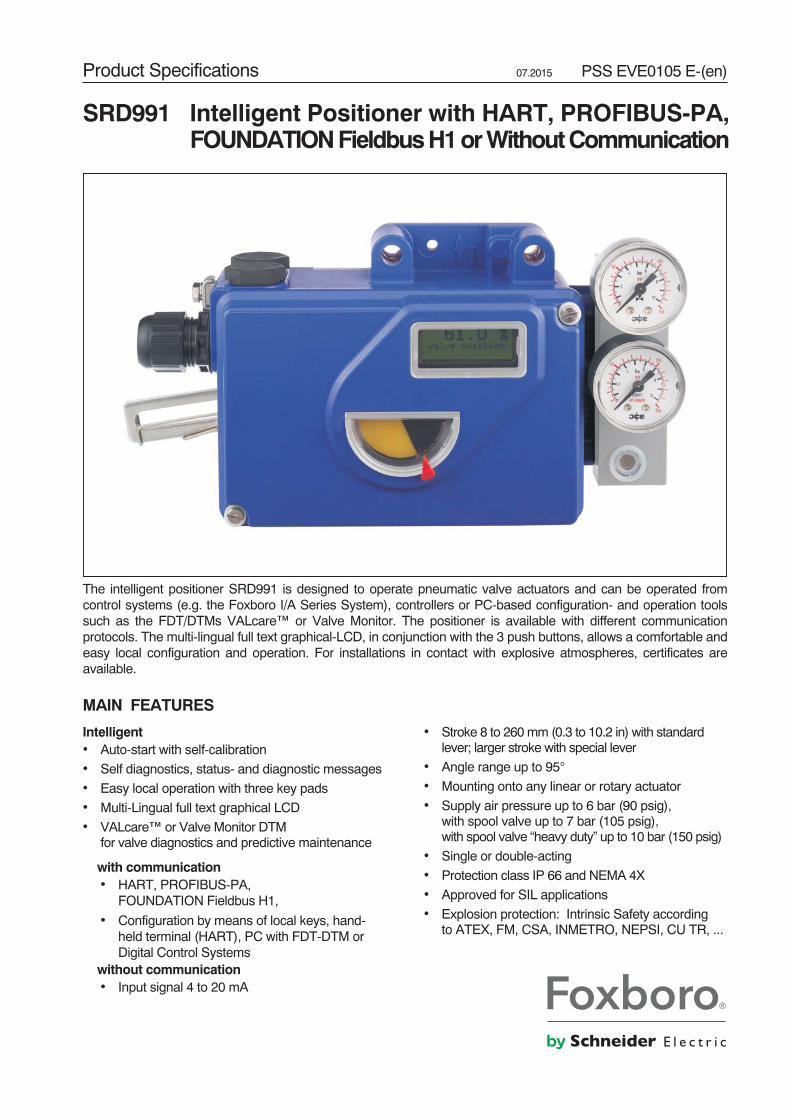
Product Specifications 07.2015 PSS EVE0105 E-(en) The intelligent positioner SRD991 is designed to operate pneumatic valve actuators and can be operated from control systems (e.g. the Foxboro I/A Series System), controllers or PC-based configuration- and operation tools such as the FDT/DTMs VALcare™ or Valve Monitor. The positioner is available with different communication protocols. The multi-lingual full text graphical-LCD, in conjunction with the 3 push buttons, allows a comfortable and easy local configuration and operation. For installations in contact with explosive atmospheres, certificates are available. MAIN FEATURES Intelligent • Auto-start with self-calibration • Self diagnostics, status- and diagnostic messages • Easy local operation with three key pads • Multi-Lingual full text graphical LCD • VALcare™ or Valve Monitor DTM for valve diagnostics and predictive maintenance with communication • HART, PROFIBUS-PA, FOUNDATION Fieldbus H1, • Configuration by means of local keys, hand- held terminal (HART), PC with FDT-DTM or Digital Control Systems without communication • Input signal 4 to 20 mA • Stroke 8 to 260 mm (0.3 to 10.2 in) with standard lever; larger stroke with special lever • Angle range up to 95° • Mounting onto any linear or rotary actuator • Supply air pressure up to 6 bar (90 psig), with spool valve up to 7 bar (105 psig), with spool valve “heavy duty” up to 10 bar (150 psig) • Single or double-acting • Protection class IP 66 and NEMA 4X • Approved for SIL applications • Explosion protection: Intrinsic Safety according to ATEX, FM, CSA, INMETRO, NEPSI, CU TR, ... SRD991 Intelligent Positioner with HART, PROFIBUS-PA, FOUNDATION Fieldbus H1 or Without Communication
Transcript of SRD991 Intelligent Positioner with HART, PROFIBUS-PA ... · 4 SRD991 PSS EVE0105 E-(en) Special...
Product Specifications 07.2015 PSS EVE0105 E-(en)
The intelligent positioner SRD991 is designed to operate pneumatic valve actuators and can be operated fromcontrol systems (e.g. the Foxboro I/A Series System), controllers or PC-based configuration- and operation toolssuch as the FDT/DTMs VALcare™ or Valve Monitor. The positioner is available with different communicationprotocols. The multi-lingual full text graphical-LCD, in conjunction with the 3 push buttons, allows a comfortable andeasy local configuration and operation. For installations in contact with explosive atmospheres, certificates areavailable.
MAIN FEATURES
Intelligent• Auto-start with self-calibration
• Self diagnostics, status- and diagnostic messages
• Easy local operation with three key pads
• Multi-Lingual full text graphical LCD
• VALcare™ or Valve Monitor DTMfor valve diagnostics and predictive maintenance
with communication• HART, PROFIBUS-PA,
FOUNDATION Fieldbus H1,
• Configuration by means of local keys, hand-held terminal (HART), PC with FDT-DTM orDigital Control Systems
without communication• Input signal 4 to 20 mA
• Stroke 8 to 260mm (0.3 to 10.2 in) with standardlever; larger stroke with special lever
• Angle range up to 95°
• Mounting onto any linear or rotary actuator
• Supply air pressure up to 6 bar (90 psig),with spool valve up to 7 bar (105 psig),with spool valve “heavy duty” up to 10 bar (150 psig)
• Single or double-acting
• Protection class IP 66 and NEMA 4X
• Approved for SIL applications
• Explosion protection: Intrinsic Safety accordingto ATEX, FM, CSA, INMETRO, NEPSI, CU TR, ...
SRD991 Intelligent Positioner with HART, PROFIBUS-PA,FOUNDATIONFieldbusH1orWithoutCommunication
2 SRD991 PSS EVE0105 E-(en)
Contents . . . . . . . . . . . . . . . . . . . Page
• Special Versions of SRD991 . . . . . . . . . . . . 4
Common technical data for all basic devices . . . 5
• Operation, Diagnostics, Service plug . . . . . . . . 6
• Electrical classification . . . . . . . . . . . . . . . 9
Extended technical data for basic devices:
• With communication HART . . . . . . . . . . . . 10
• With communication PROFIBUSorFOUNDATIONF. 11
• Basic device without communication (4-20 mA) . . 12
Additional equipment for basic devices . . . . . 13(built into the basic device)
• Pressure sensors for premium diagnostics . . . . 13
One Option board with additional inputs / outputs:• 2 Binary inputs or. . . . . . . . . . . . . . . . . 14• 2 Binary outputs or . . . . . . . . . . . . . . . . 15• 2 Binary in / outputs or . . . . . . . . . . . . . . 16• Position feedback and Alarm or. . . . . . . . . . 17• Entry for remote Potentiometer . . . . . . . . . . 18
Additional built-in• Limit signal switch. . . . . . . . . . . . . . . . . 19
FUNCTIONAL DESIGNATIONS . . . . . . . . . . 21
MODEL CODES SRD991 . . . . . . . . . . . . . 22
ACCESSORIES for mounting to the positioner:• Booster • Manifolds • Gauge manifolds . . . . . 24
ATTACHMENT to actuators . . . . . . . . . . . . 27
DIMENSIONS . . . . . . . . . . . . . . . . . . . 31
� � � �
� � � � � � � � �� � � � �
� � � � � � � � � � � � � � �� � � � � � � � � � � � � � � � � � � � � ! � � � � � " # � � � � " � � $ � % & � � � �� ' ( � � � � � � � � � � � � � � � (
� ) � � & � � ' % �( � % % � � � � � � � � (
� � & � $ � � � % �
! $ ' * � � $) � � �
� ' $ � � � ' $� $ � � ' �
� � � � $ '+ � � , � � %
PSS EVE0105 E-(en) SRD991 3OVERVIEW
The SRD991 consists of a basic device with a digital controller that supports different communication protocols(or also simply 4-20 mA input). Into this basic device, additional equipment can be built such as plug-in cards forelectrical input/output signals, position feedback and pressure sensors.
The pneumatic part is available in different versions (single / double acting or spool valve). For very largeactuators, boosterswith increased air capacity can be flanged on. Also, differentmanifolds for connection of gaugescan be flanged on. For the pneumatic screw connections, we offer different threads in the housing and adapters.
For use in hazardous areas, there are approvals according to ATEX, FM, CSA, etc.
The device can be configured locally by means of push buttons and LCD / LED, or with PC + EDC82 Modemconnected to the service plug of the SRD991. By means of communication, the device can be configured remotelyvia FDT/DTM.
A large variety of attachment kits for all common valves and actuators are available. The list “AttachmentKits.pdf” isupdated continuously and can be found on the Internet here .
For high temperature or high vibration application, we recommend tomount the SRD991 remotely and not directlyon the valve. For this, use the potentiometer unit (like the SRI990 - TXQxxxxx - H).Please consult TI EVE0105_R for specifications.
Toensure thehighperformanceof thepositioner,weofferAdvancedDiagnostics and PremiumDiagnosticsutilities:
Premium Diagnostics Advanced Diagnostics
Autostart Yes Yes
Custom Characterization Yes Yes
Autodiagnostic Yes Yes
Alarm Management Yes Yes
Alarm Output for Switching (with Optionboard) Yes Yes
Status List acc. NE107 Yes Yes
Position History Yes Yes
Response History Yes Yes
On Line Friction Yes
Stepping Signature Yes
Ramping Signature Yes
Sensitivity Signature Yes
Valve Signature Yes
PST (Partial Stroke Test) Yes
PST Predictive Maintenance Yes
Additional equipment, built into the basic device:
Option Board “2 Binary Inputs” or B2 external switches (supplied by SRD) release a control function in theSRD, e.g. "close valve" (configurable)
Option Board “2 Binary Outputs” or P2 binary outputs (to be supplied externally) become active during valuelimit in excess of the measured valve position
Option Board “2 Binary Inputs/Outputs” or E2 channels, each configurable as an input or output(to be supplied externally)
Option Board “Position Feedback” F1 output 4-20mA (to be supplied externally) gives stroke / angle of rotation,1 alarm output becomes active with a configurable event
Limit switchT,U,R,V
Supplies NAMUR signals when exceeding or falling below of two limitvalues. Inductive sensors, independent of the controller,in normal or safety version or three-wire, or micro switches
D Entry for remote potentiometer of external potentiometer unit
Pressure sensors2 sensors measure the pressure of supply air and output y1 for Premi-um Diagnostics; the values are passed on via communication
LCD Full text graphic LCD in 3 languages
Accessories like Manifolds and Boosters see page 24.
4 SRD991 PSS EVE0105 E-(en)
Special Versions of SRD991:
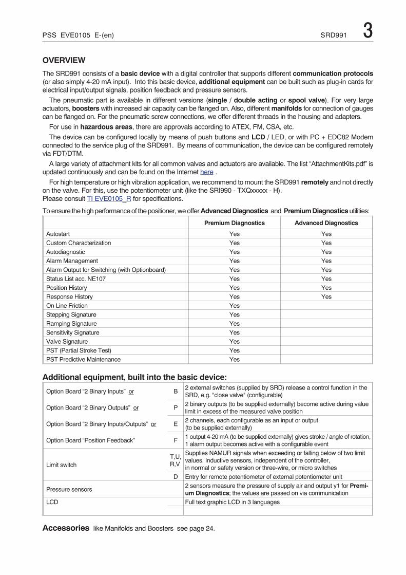
SRD991 Stainless Steel HousingTo be order with model code SRD991-xxxxxxxx-Zxxx
Please consult TI EVE0105 INOX for specifications.For dimensional drawings see page 33.
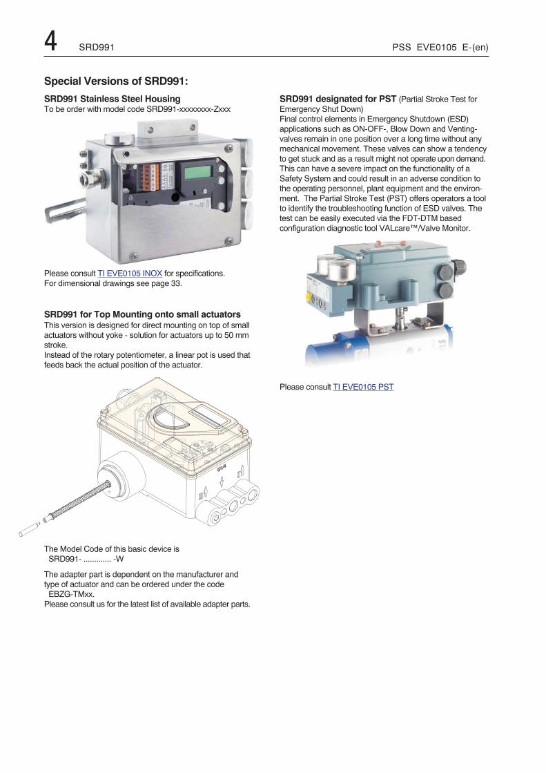
SRD991 for Top Mounting onto small actuatorsThis version is designed for direct mounting on top of smallactuators without yoke - solution for actuators up to 50 mmstroke.Instead of the rotary potentiometer, a linear pot is used thatfeeds back the actual position of the actuator.
The Model Code of this basic device isSRD991- ............. -W
The adapter part is dependent on the manufacturer andtype of actuator and can be ordered under the codeEBZG-TMxx.Please consult us for the latest list of available adapter parts.
SRD991 designated for PST (Partial Stroke Test forEmergency Shut Down)Final control elements in Emergency Shutdown (ESD)applications such as ON-OFF-, Blow Down and Venting-valves remain in one position over a long time without anymechanical movement. These valves can show a tendencyto get stuck and as a result might not operate upon demand.This can have a severe impact on the functionality of aSafety System and could result in an adverse condition tothe operating personnel, plant equipment and the environ-ment. The Partial Stroke Test (PST) offers operators a toolto identify the troubleshooting function of ESD valves. Thetest can be easily executed via the FDT-DTM basedconfiguration diagnostic tool VALcare™/Valve Monitor.
Please consult TI EVE0105 PST
PSS EVE0105 E-(en) SRD991 5FUNCTIONAL SPECIFICATIONS (common data for all versions)
Travel rangeStroke range . . . . . . . . . . . . 8 to 260 mm (0.3 to 10.2 in)with standard feedback levers; special levers on request
Rotation angle range . . . . . . up to 95° without mechanicalstop
SupplySupply air pressure . . . . . . . 1.4 to 6 bar (20 to 90 psig)
with spool valve 1) . . . . . . 1.4 to 7 bar (20 to 105 psig)Output to actuator . . . . . . . . 0 to ~100 % of supply airpressure (up to 5.5 bar at 6 bar supply air pressure)with spool valve heavy duty2): 4 to 10 bar
Air supply. . . . . . . . . . . . . . . according to ISO 8573-1- Solid particle size and density class 2- Oil rate. . . . . . . . . . . . . . . class 3- Pressure dew point 10 K under ambient temperatureThe use of filter regulator for air supply of positioner isstrongly recommended. It reduces the air pressure toactuator’s maximum pressure and keeps it constant.
For supply with Natural Gas instead of compressed airplease consult TI EVE0105_G .
Air output ln/h (scfh)at max. deviation, single and double acting:
Supply airpressurebar (psig)
1.4(20)
3(45)
6(90)
StandardAmplifier
2 700(95)
5 000(177)
7 500(265)
with SpoolValve 1)
6 000(211)
12 000(423)
18 000(636)
“Heavy duty” spool valve 2) is able to deliver up to 55,000ln/h at 10 bar. Please consult TI EVE0105 INOX .
Note: The use of boosters in connection with Spool valveis not recommended.
Air consumption (steady state) ln/h (scfh)
Supply airpressurebar (psig)
1.4(20)
3(45)
6(90)
singleacting
80(2.8)
130(4.6)
220(7.8)
doubleacting
130(4.6)
230(8.1)
430(15.2)
SpoolValve
100(3.5)
240(8.5)
500(17.7)
Response characteristic 3) 4)
Sensitivity . . . . . . . . . . . . . . < 0.1 % of travel spanNon-linearity (terminalbased adjustment) . . . . . . . . < 0.4 % of travel spanHysteresis . . . . . . . . . . . . . . < 0.3 % of travel spanSupply air dependence. . . . . < 0.1 % / 1 bar (15 psi)Temperature effect. . . . . . . . < 0.3 % / 10 KMechanical vibration10 to 60 Hz up to 0.14 mm,60 to 500 Hz up to 2 g < 0.25 % of travel span
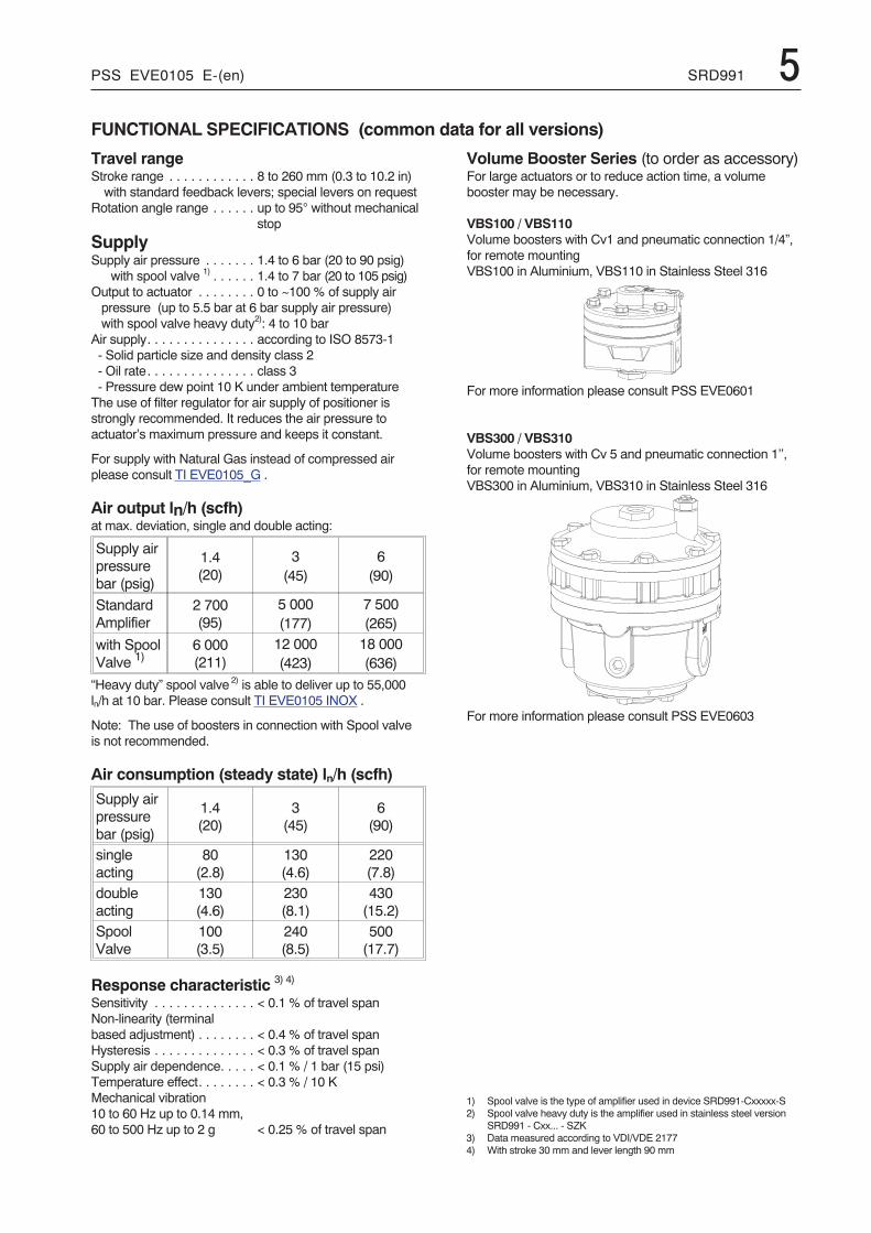
Volume Booster Series (to order as accessory)For large actuators or to reduce action time, a volumebooster may be necessary.
VBS100 / VBS110Volume boosters with Cv1 and pneumatic connection 1/4”,for remote mountingVBS100 in Aluminium, VBS110 in Stainless Steel 316
For more information please consult PSS EVE0601
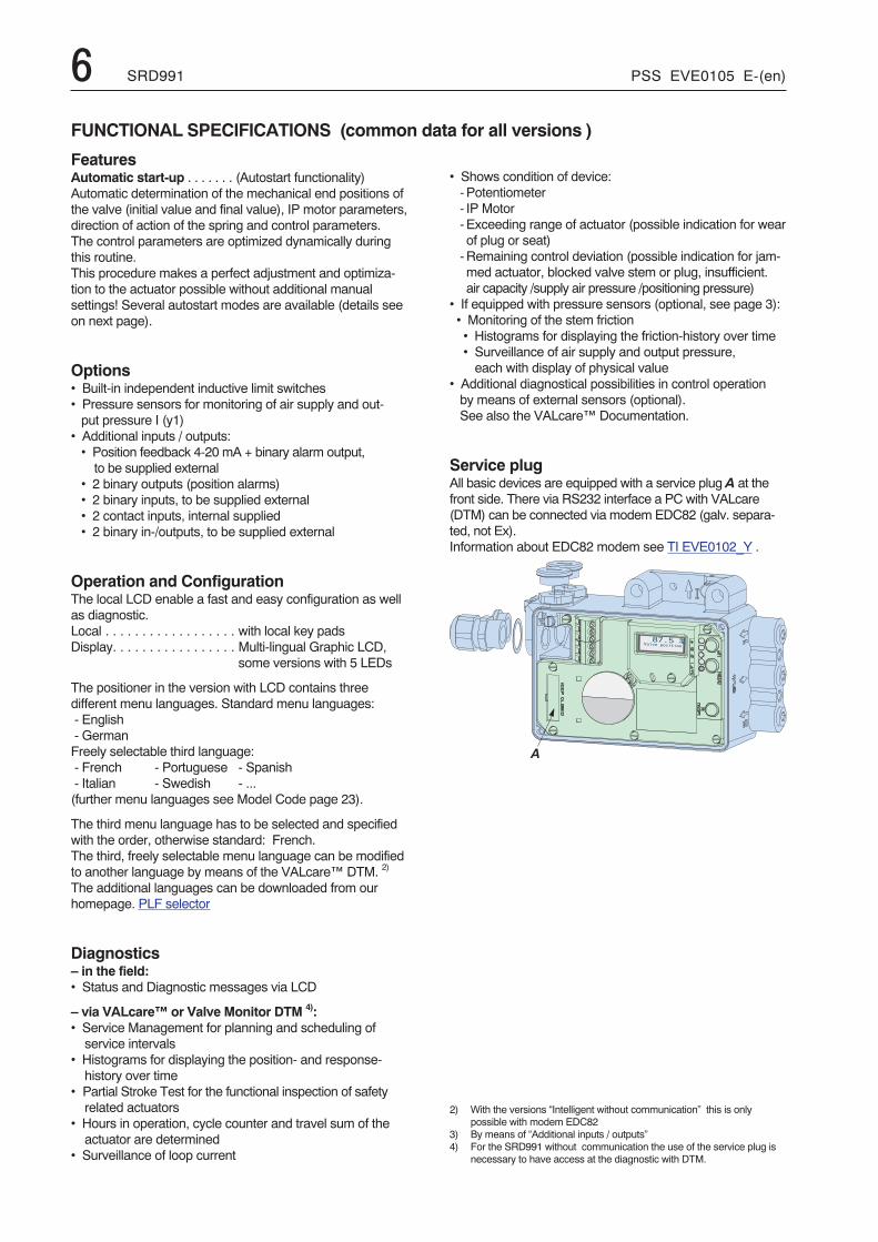
VBS300 / VBS310Volume boosters with Cv 5 and pneumatic connection 1’’,for remote mountingVBS300 in Aluminium, VBS310 in Stainless Steel 316
For more information please consult PSS EVE0603
1) Spool valve is the type of amplifier used in device SRD991-Cxxxxx-S2) Spool valve heavy duty is the amplifier used in stainless steel version
SRD991 - Cxx... - SZK3) Data measured according to VDI/VDE 21774) With stroke 30 mm and lever length 90 mm
�
6 SRD991 PSS EVE0105 E-(en)
FUNCTIONAL SPECIFICATIONS (common data for all versions )
FeaturesAutomatic start-up . . . . . . . (Autostart functionality)Automatic determination of the mechanical end positions ofthe valve (initial value and final value), IP motor parameters,direction of action of the spring and control parameters.The control parameters are optimized dynamically duringthis routine.This procedure makes a perfect adjustment and optimiza-tion to the actuator possible without additional manualsettings! Several autostart modes are available (details seeon next page).
Options• Built-in independent inductive limit switches• Pressure sensors for monitoring of air supply and out-put pressure I (y1)
• Additional inputs / outputs:• Position feedback 4-20 mA + binary alarm output,to be supplied external
• 2 binary outputs (position alarms)• 2 binary inputs, to be supplied external• 2 contact inputs, internal supplied• 2 binary in-/outputs, to be supplied external
Operation and ConfigurationThe local LCD enable a fast and easy configuration as wellas diagnostic.Local . . . . . . . . . . . . . . . . . . with local key padsDisplay. . . . . . . . . . . . . . . . . Multi-lingual Graphic LCD,
some versions with 5 LEDs
The positioner in the version with LCD contains threedifferent menu languages. Standard menu languages:- English- GermanFreely selectable third language:- French - Portuguese - Spanish- Italian - Swedish - ...(further menu languages see Model Code page 23).
The third menu language has to be selected and specifiedwith the order, otherwise standard: French.The third, freely selectable menu language can be modifiedto another language by means of the VALcare™ DTM. 2)
The additional languages can be downloaded from ourhomepage. PLF selector
Diagnostics– in the field:• Status and Diagnostic messages via LCD
– via VALcare™ or Valve Monitor DTM 4):• Service Management for planning and scheduling ofservice intervals
• Histograms for displaying the position- and response-history over time
• Partial Stroke Test for the functional inspection of safetyrelated actuators
• Hours in operation, cycle counter and travel sum of theactuator are determined
• Surveillance of loop current
• Shows condition of device:-Potentiometer- IP Motor-Exceeding range of actuator (possible indication for wearof plug or seat)-Remaining control deviation (possible indication for jam-med actuator, blocked valve stem or plug, insufficient.air capacity /supply air pressure /positioning pressure)
• If equipped with pressure sensors (optional, see page 3):• Monitoring of the stem friction• Histograms for displaying the friction-history over time• Surveillance of air supply and output pressure,each with display of physical value
• Additional diagnostical possibilities in control operationby means of external sensors (optional).See also the VALcare™ Documentation.
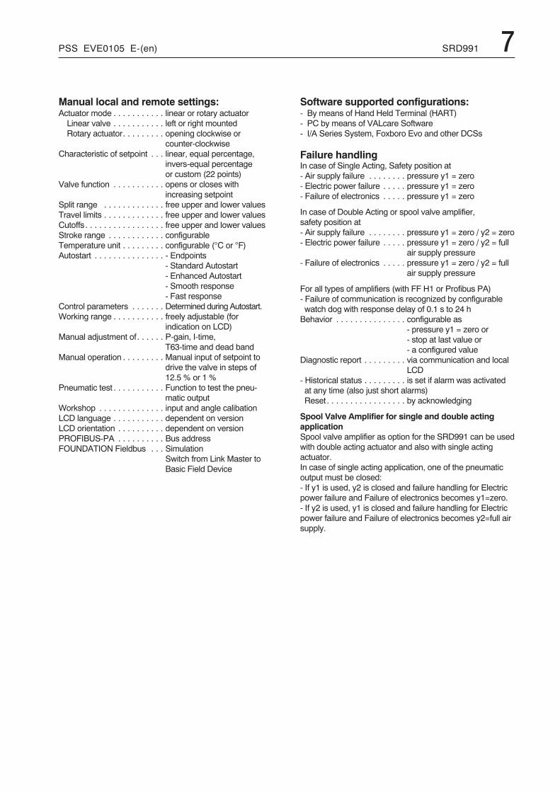
Service plugAll basic devices are equipped with a service plug A at thefront side. There via RS232 interface a PC with VALcare(DTM) can be connected via modem EDC82 (galv. separa-ted, not Ex).Information about EDC82 modem see TI EVE0102_Y .
2) With the versions “Intelligent without communication” this is onlypossible with modem EDC82
3) By means of “Additional inputs / outputs”4) For the SRD991 without communication the use of the service plug is
necessary to have access at the diagnostic with DTM.
PSS EVE0105 E-(en) SRD991 7
Manual local and remote settings:Actuator mode . . . . . . . . . . . linear or rotary actuatorLinear valve . . . . . . . . . . . left or right mountedRotary actuator. . . . . . . . . opening clockwise or
counter-clockwiseCharacteristic of setpoint . . . linear, equal percentage,
invers-equal percentageor custom (22 points)
Valve function . . . . . . . . . . . opens or closes withincreasing setpoint
Split range . . . . . . . . . . . . . free upper and lower valuesTravel limits . . . . . . . . . . . . . free upper and lower valuesCutoffs. . . . . . . . . . . . . . . . . free upper and lower valuesStroke range . . . . . . . . . . . . configurableTemperature unit . . . . . . . . . configurable (°C or °F)Autostart . . . . . . . . . . . . . . . - Endpoints
- Standard Autostart- Enhanced Autostart- Smooth response- Fast response
Control parameters . . . . . . . Determined during Autostart.Working range . . . . . . . . . . . freely adjustable (for
indication on LCD)Manual adjustment of. . . . . . P-gain, I-time,
T63-time and dead bandManual operation . . . . . . . . . Manual input of setpoint to
drive the valve in steps of12.5 % or 1 %
Pneumatic test . . . . . . . . . . . Function to test the pneu-matic output
Workshop . . . . . . . . . . . . . . input and angle calibationLCD language . . . . . . . . . . . dependent on versionLCD orientation . . . . . . . . . . dependent on versionPROFIBUS-PA . . . . . . . . . . Bus addressFOUNDATION Fieldbus . . . Simulation
Switch from Link Master toBasic Field Device
Software supported configurations:- By means of Hand Held Terminal (HART)- PC by means of VALcare Software- I/A Series System, Foxboro Evo and other DCSs
Failure handlingIn case of Single Acting, Safety position at- Air supply failure . . . . . . . . pressure y1 = zero- Electric power failure . . . . . pressure y1 = zero- Failure of electronics . . . . . pressure y1 = zero
In case of Double Acting or spool valve amplifier,safety position at- Air supply failure . . . . . . . . pressure y1 = zero / y2 = zero- Electric power failure . . . . . pressure y1 = zero / y2 = full
air supply pressure- Failure of electronics . . . . . pressure y1 = zero / y2 = full
air supply pressure
For all types of amplifiers (with FF H1 or Profibus PA)- Failure of communication is recognized by configurablewatch dog with response delay of 0.1 s to 24 hBehavior . . . . . . . . . . . . . . . configurable as
- pressure y1 = zero or- stop at last value or- a configured value
Diagnostic report . . . . . . . . . via communication and localLCD
- Historical status . . . . . . . . . is set if alarm was activatedat any time (also just short alarms)Reset. . . . . . . . . . . . . . . . . by acknowledging
Spool Valve Amplifier for single and double actingapplicationSpool valve amplifier as option for the SRD991 can be usedwith double acting actuator and also with single actingactuator.In case of single acting application, one of the pneumaticoutput must be closed:- If y1 is used, y2 is closed and failure handling for Electricpower failure and Failure of electronics becomes y1=zero.- If y2 is used, y1 is closed and failure handling for Electricpower failure and Failure of electronics becomes y2=full airsupply.
8 SRD991 PSS EVE0105 E-(en)
PHYSICAL SPECIFICATIONS (common data for all versions)
MountingAttachment to stroke actuators- direct, FlowPak/FlowTop . . with attachment kit EBZG–E
- for casting yokeacc. to IEC 534-6 (NAMUR) with attachment kit EBZG–H
or –H1- for pillar yokeacc. to IEC 534-6 (NAMUR) with attachment kit EBZG–K
or –K1Stroke range with feedback lever:- standard (EBZG-A ) 8 to 70 mm / 0.31 to 2.76 in- extended (EBZG-B ) 60 to 120 mm / 2.36 to 4.72 in- extended (EBZG-A1) 110 to 260 mm / 4.33 to 10.24 inLarger stroke ranges can be realised with special levers.
Attachment to rotary actuatorsacc. to VDI/VDE 3845 ...with attachment kit . . . . . . . . . EBZG -R- Further attachment kits see ModelCodes page 26- Mounting orientation see attachment dimensions startingfrom page 27
MaterialsHousing and covers . . . . . . . Aluminum (Alloy No. 230)
finished with DD-varnishAll moving parts offeedback system . . . . . . . . . 1.4306 / 1.4571 / 1.4104Attachment kits . . . . . . . . . . V4A or Aluminum, finished
with DD varnish(depending upon version) . . (Alloy No. 230)Mounting bracket . . . . . . . . . Aluminum (Alloy No. 230)Pneumatic diaphragms . . . . PVMQ (Silicone elastomer,
suitable for use in the paintindustry)
WeightSingle acting . . . . . . . . . . . . approx. 1.7 kg (3.7 lbs)Double acting. . . . . . . . . . . . approx. 2.0 kg (4.4 lbs)
Pneumatic connectionNAMUR mounting . . . . . . . . G 1/4 for pipe diameter 6 to12 mm (0.24 to 0.47 in) for air supply and outputs y1, y2to the actuator; 1/4-18NPT with additional connectionmanifold
Direct mounting . . . . . . . . . . Instead of the output y1, anair connection on the back with O-ring will be used(closed at NAMUR mounting).
Electrical ConnectionLine entry. . . . . . . . . . . . . . . 1 or 2 cable glands 1/2-14 NPTor M20 x1.5 (others with Adapter AD-...)
Cable diameter . . . . . . . . . . 6 to 12 mm (0.24 to 0.47 in)Screw terminals . . . . . . . . . . 2 terminals for input,4 terminals for additional inputs / outputs;Tightening torque . . . . . . . min. 0.5 Nm, max. 0.6 NmWire cross section . . . . . . solid wire 0.5 to 6 mm2
stranded wire 0.5 to 4 mm2
crimped wire . . . . . . . . . 0.5 to 2.5mm2 (AWG21-14)Test sockets . . . . . . . . . . . integrated in terminals, for
options and communicatorconnection
Ambient conditionsOperating conditions . . . . . . acc. to IEC 654-1The device can be operated at a class Dx locationAmbient temperatureOperation 1) . . . . . . . . . . . –40 to 80 °C (–40 to 176 °F)Transport and storage . . . –40 to 80 °C (–40 to 176 °F)If the device is exposed to sunlight and the temperature may riseabove 80 °C, we recommend a sun shade.Storage conditionsacc. to IEC 60721-3-1: . . . 1K5; 1B1; 1C2; 1S3; 1M2
IndicatorsLCD (visible) 2) . . . . . . . . . –25 to 70 °C (–13 to 176 °F)LEDs (if present). . . . . . . . –40 to 80 °C (–40 to 176 °F)
Relative humidity . . . . . . . . . up to 100 %Protection class 3)
acc. to IEC 529. . . . . . . . . IP 66acc. to NEMA . . . . . . . . . . Type 4X
Electromagnetic compatibility EMCOperating conditions . . . . . . industrial environmentImmunity according toEN 61326 . . . . . . . . . . . . . . fulfilledIEC 61326 . . . . . . . . . . . . . . fulfilledEN 61000-6-2 . . . . . . . . . . . fulfilled
Emission according toEN 61326Class A and Class B. . . . . fulfilled
EN 61000-6-4 . . . . . . . . . . . fulfilledEN 55011 Group 1,Class A and Class B. . . . . fulfilled
NAMUR recommendationEMV NE21 . . . . . . . . . . . . fulfilled
SAFETY REQUIREMENTS
CE labelElectromagneticCompatibility 4) . . . . . . . . . . . 2004/108/ECLow-voltage regulation . . . . . not applicable
SafetyAccording to EN 61010-1(or IEC 1010-1) . . . . . . . . . . Safety class III
Overvoltage Category IInternal fuses . . . . . . . . . . . . only with PROFIBUS or
FOUNDATION Fieldbus,but not replaceable
External fuses . . . . . . . . . . . Limitation of power suppliesfor fire protection must be observed acc. to EN 61010-1,appendix F (bzw. IEC 1010-1).
1) Details see Certificates of Conformity.With Limit Switches Code T only –20 °C.With Limit Switches Code R only –25 to 70 °C
2) Below –20 °C the LCD reacts only slowly; above 70 °C the backgroundbecomes dark
3) Under service as directed4) With PROFIBUS or FOUNDATION Fieldbus only, if shield of wiring is
grounded on both sides5) Pneumatic connection 1/4-18 NPT made with a seperate manifold
delivered together with the device
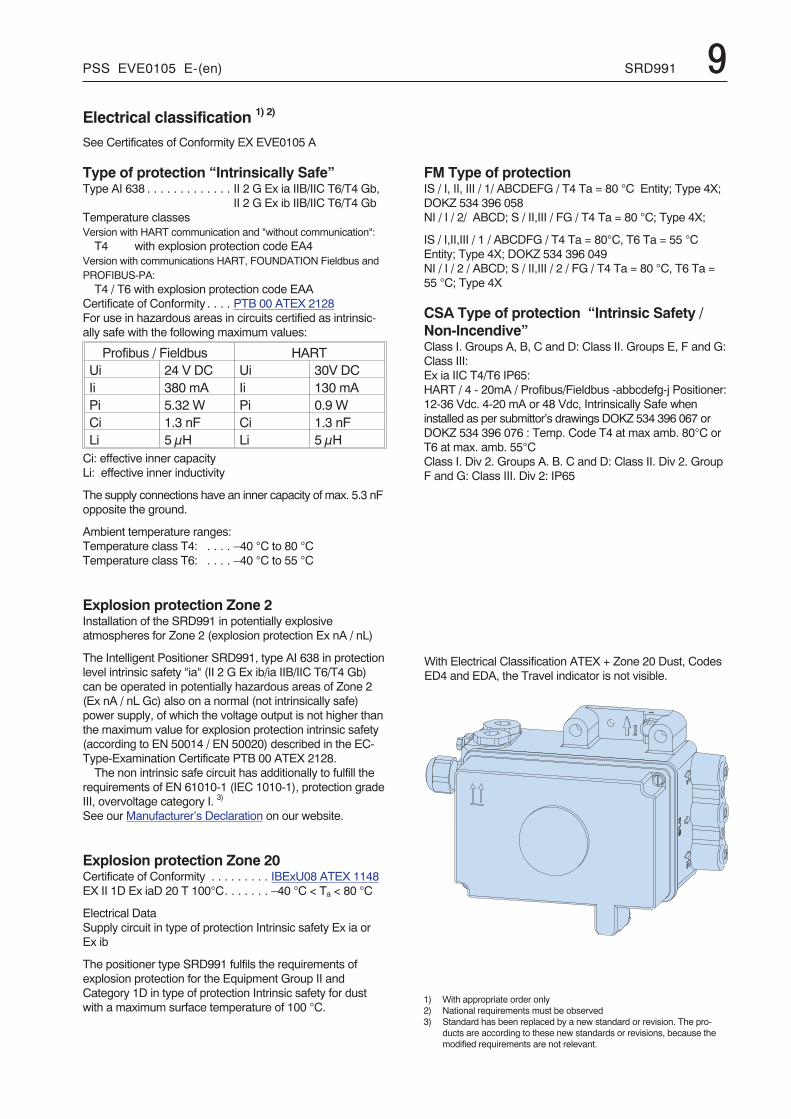
PSS EVE0105 E-(en) SRD991 9Electrical classification 1) 2)
See Certificates of Conformity EX EVE0105 A
Type of protection “Intrinsically Safe”Type AI 638 . . . . . . . . . . . . . II 2 G Ex ia IIB/IIC T6/T4 Gb,
II 2 G Ex ib IIB/IIC T6/T4 GbTemperature classesVersion with HART communication and "without communication":T4 with explosion protection code EA4
Version with communications HART, FOUNDATION Fieldbus andPROFIBUS-PA:T4 / T6 with explosion protection code EAA
Certificate of Conformity . . . . PTB 00 ATEX 2128For use in hazardous areas in circuits certified as intrinsic-ally safe with the following maximum values:
Profibus / Fieldbus HARTUi 24 V DC Ui 30V DCIi 380 mA Ii 130 mAPi 5.32 W Pi 0.9 WCi 1.3 nF Ci 1.3 nFLi 5 μH Li 5 μHCi: effective inner capacityLi: effective inner inductivity
The supply connections have an inner capacity of max. 5.3 nFopposite the ground.
Ambient temperature ranges:Temperature class T4: . . . . –40 °C to 80 °CTemperature class T6: . . . . –40 °C to 55 °C
Explosion protection Zone 2Installation of the SRD991 in potentially explosiveatmospheres for Zone 2 (explosion protection Ex nA / nL)
The Intelligent Positioner SRD991, type AI 638 in protectionlevel intrinsic safety "ia" (II 2 G Ex ib/ia IIB/IIC T6/T4 Gb)can be operated in potentially hazardous areas of Zone 2(Ex nA / nL Gc) also on a normal (not intrinsically safe)power supply, of which the voltage output is not higher thanthe maximum value for explosion protection intrinsic safety(according to EN 50014 / EN 50020) described in the EC-Type-Examination Certificate PTB 00 ATEX 2128.The non intrinsic safe circuit has additionally to fulfill the
requirements of EN 61010-1 (IEC 1010-1), protection gradeIII, overvoltage category I. 3)
See our Manufacturer’s Declaration on our website.
Explosion protection Zone 20Certificate of Conformity . . . . . . . . . IBExU08 ATEX 1148EX II 1D Ex iaD 20 T 100°C. . . . . . . –40 °C < Ta < 80 °C
Electrical DataSupply circuit in type of protection Intrinsic safety Ex ia orEx ib
The positioner type SRD991 fulfils the requirements ofexplosion protection for the Equipment Group II andCategory 1D in type of protection Intrinsic safety for dustwith a maximum surface temperature of 100 °C.
FM Type of protectionIS / I, II, III / 1/ ABCDEFG / T4 Ta = 80 °C Entity; Type 4X;DOKZ 534 396 058NI / I / 2/ ABCD; S / II,III / FG / T4 Ta = 80 °C; Type 4X;
IS / I,II,III / 1 / ABCDFG / T4 Ta = 80°C, T6 Ta = 55 °CEntity; Type 4X; DOKZ 534 396 049NI / I / 2 / ABCD; S / II,III / 2 / FG / T4 Ta = 80 °C, T6 Ta =55 °C; Type 4X
CSA Type of protection “Intrinsic Safety /Non-Incendive”Class I. Groups A, B, C and D: Class II. Groups E, F and G:Class III:Ex ia IIC T4/T6 IP65:HART / 4 - 20mA / Profibus/Fieldbus -abbcdefg-j Positioner:12-36 Vdc. 4-20 mA or 48 Vdc, Intrinsically Safe wheninstalled as per submittor’s drawings DOKZ 534 396 067 orDOKZ 534 396 076 : Temp. Code T4 at max amb. 80°C orT6 at max. amb. 55°CClass I. Div 2. Groups A. B. C and D: Class II. Div 2. GroupF and G: Class III. Div 2: IP65
With Electrical Classification ATEX + Zone 20 Dust, CodesED4 and EDA, the Travel indicator is not visible.
1) With appropriate order only2) National requirements must be observed3) Standard has been replaced by a new standard or revision. The pro-
ducts are according to these new standards or revisions, because themodified requirements are not relevant.
10 SRD991 PSS EVE0105 E-(en)
SRD991 with HART communicationSRD991-xHxxxxSignal Input . . . . . . . . . . . . . Two wire systemReverse polarity protection. . standard featureSignal range . . . . . . . . . . . . 4-20 mAOperating range. . . . . . . . . . 3.6 to 21.5 mAInput voltage . . . . . . . . . . . . DC 12 to 36 V 1) (unloaded)Load . . . . . . . . . . . . . . . . . . 420 Ohms, 8.4 V at 20 mACommunication signal . . . . . HART, 1200 Baud, FSK
(Frequency Shift Key)modulated on 4-20 mA0.5 Vpp at 1 kOhm load
Input impedance Zi. . . . . . . . Z = 320 Ohmsfor ac voltage 0.5 to 10 kHz with < 3 dB non-linearityCable capacity and inductance see HART standardspecifications (e.g. C < 100 nF).Impedance of other devices at the input (parallel or serial)must be within HART spec.Applications without communication require not to exceedinput capacitance parallel to the input not higher than 100 μF.Start-up time . . . . . . . . . . . . approx. 3 secInterruption time without power down:with LCD . . . . . . . . . . . . . typ. 80 ms 2)
1) On request we can specify higher voltage limits2) Worst case conditions 4-20 mA, with position feedback option, i/p-output
with max. current
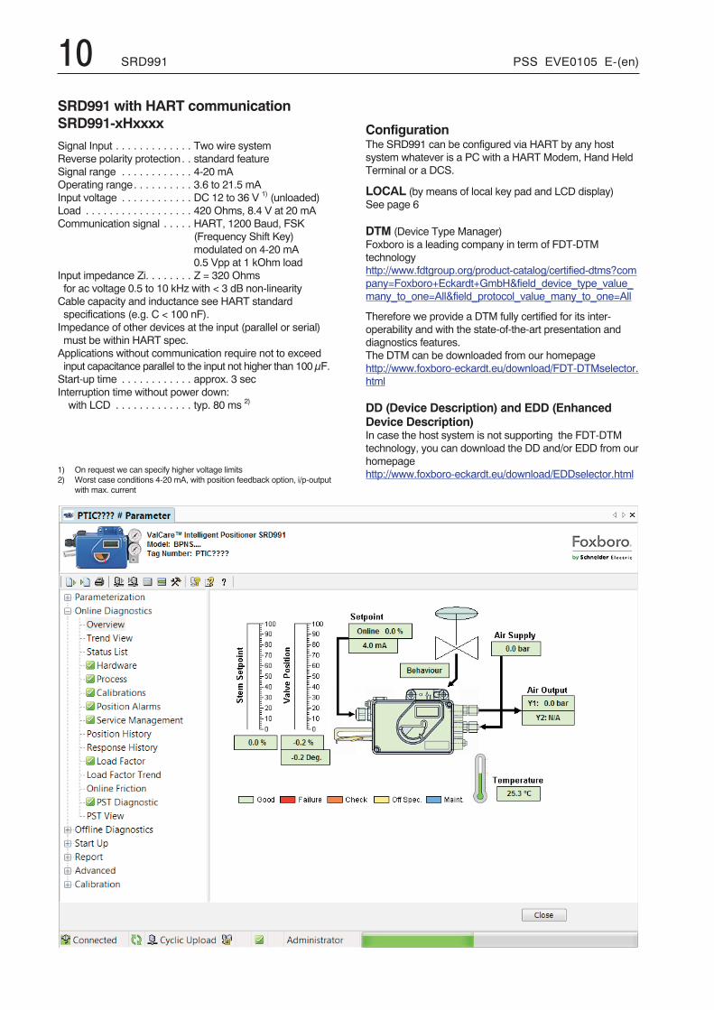
ConfigurationThe SRD991 can be configured via HART by any hostsystem whatever is a PC with a HART Modem, Hand HeldTerminal or a DCS.
LOCAL (by means of local key pad and LCD display)See page 6
DTM (Device Type Manager)Foxboro is a leading company in term of FDT-DTMtechnologyhttp://www.fdtgroup.org/product-catalog/certified-dtms?company=Foxboro+Eckardt+GmbH&field_device_type_value_many_to_one=All&field_protocol_value_many_to_one=All
Therefore we provide a DTM fully certified for its inter-operability and with the state-of-the-art presentation anddiagnostics features.The DTM can be downloaded from our homepagehttp://www.foxboro-eckardt.eu/download/FDT-DTMselector.html
DD (Device Description) and EDD (EnhancedDevice Description)In case the host system is not supporting the FDT-DTMtechnology, you can download the DD and/or EDD from ourhomepagehttp://www.foxboro-eckardt.eu/download/EDDselector.html
PSS EVE0105 E-(en) SRD991 11SRD991 with communication PROFIBUS-PA and FOUNDATION Fieldbus H1SRD991-xPxxxx or SRD991-xQxxxx
PROFIBUS-PAData transfer . . . . . . . . . . . . according to PROFIBUS- PA
profile class B based on EN50170 and DIN 19245 part 4
GSD file . . . . . . . . . . . . . . . . the actual file can be down-loaded from our homepage
ConfigurationLocal / Display . . . . . . . . . . . see page 6Software . . . . . . . . . . . . . . . VALcare™ -DTMHardware. . . . . . . . . . . . . . . PC- or PCMCIA- interfaces
from SoftingI/A Series System . . . . . . . . FBM 223 in combination with
CP60Other control systems . . . . . All Profibus-PA- compatible,
e.g. SiemensSIMATICPDM(Process Device Manager)
FOUNDATION Fieldbus H1Data transfer . . . . . . . . . . . . FF Specification Rev. 1.4,
Link-Master (LAS)Two revisions of Firmware can be selected for theFOUNDATION Fieldbus devices in the model code of thepositioner. The selection of the Firmware revision isdepending of the DCS compatibility, the DD Files alreadyinstalled in the DCS and the installed base on your site.Double check interoperability of following characteristics
with your DCS before ordering!
When selected Firmware FF16 in the model code :Certified according to . . . . . . ITK 4.6Function Blocks . . . . . . . . PID, AO, 2xDI, 1xDO
Transducer, ResourceWhen selected Firmware FF18 in the model code :Certified according to . . . . . . ITK 6.0.1Function Blocks . . . . . . . . PID, AO, 4xDI, 1xDO, IS, OS,
AI, MAI, Transducer,Resource
Additional functionality . . . Flat AddressingDD files . . . . . . . . . . . . . . . . the actual file can be down-
loaded from our homepageConfigurationLocal / Display . . . . . . . . . . . see page 6Software . . . . . . . . . . . . . . . VALcare™ -DTM
or National InstrumentsNI-FBUS configurator
Hardware. . . . . . . . . . . . . . . FBUS-interfaces fromNational Instruments(AT-FBUS andPCMCIA- FBUS)
I/A Series System . . . . . . . . FBM220 or FBM221 incombination with CP60
Other control systems . . . . . All FOUNDATION FieldbusH1- compatible, e.g. SMAR, Fisher Rosemount Delta-V,Honeywell, Yokogawa, ABB
1) Data of ”Intrinsically Safe” version
For both fieldbus devicesInput signal . . . . . . . . . . . . . digitalSupply voltage . . . . . . . . . . . DC 9 to 32 V 1)
max. Supply voltage. . . . . . . DC 36 VOperating current . . . . . . . . . 10.5mA±0.5mA (base current)Current amplitude . . . . . . . . ± 8 mAFault current. . . . . . . . . . . . . base current + 0 mA(base current + 4 mA by means of independentFDE-safety circuit) according to IEC 1158-2
Operating values . . . . . . . . . according to IEC 1158-2Start-up time (init phase) . . . approx. 2 secBus connection . . . . . . . . . . Fieldbus interface based onIEC 1158-2 according to FISCO-Model
Power supply . . . . . . . . . . . . Power supply is achieveddependant on the application by means of fieldbuspower supply units or segment coupler
Electrical classification theretosee Page 9
12 SRD991 PSS EVE0105 E-(en)
SRD991 without communicationSRD991-xDxxxxSignal Input . . . . . . . . . . . . . Two wire systemReverse polarity protection. . Standard featureSignal range . . . . . . . . . . . . 4-20 mAOperating range. . . . . . . . . . 3.6 to 21.5 mAInput voltage . . . . . . . . . . . . DC 8.5 to 36 V 1) (unloaded)Load . . . . . . . . . . . . . . . . . . 300 Ohms, 6 V at 20 mAWith applications without communication the capacity
parallel to input may not be higher than 100 μF.
Start-up time . . . . . . . . . . . . approx. 3 secInterruption time without power down:with LCD . . . . . . . . . . . . . typ. 80 ms 2)
ConfigurationLocal / Display . . . . . . . . . . . see page 6Software . . . . . . . . . . . . . . . VALcare™ (DTM)Hardware. . . . . . . . . . . . . . . per modem EDC82
1) On request we can specify higher voltage limits2) Worst case conditions 4-20 mA, with position feedback option, i/p-output
with max. current
Electrical classification theretosee Page 9
PSS EVE0105 E-(en) SRD991 13
� � � � � � � � � � � � � � � � � � �� � � � � �
� �
� �� �
�
� �
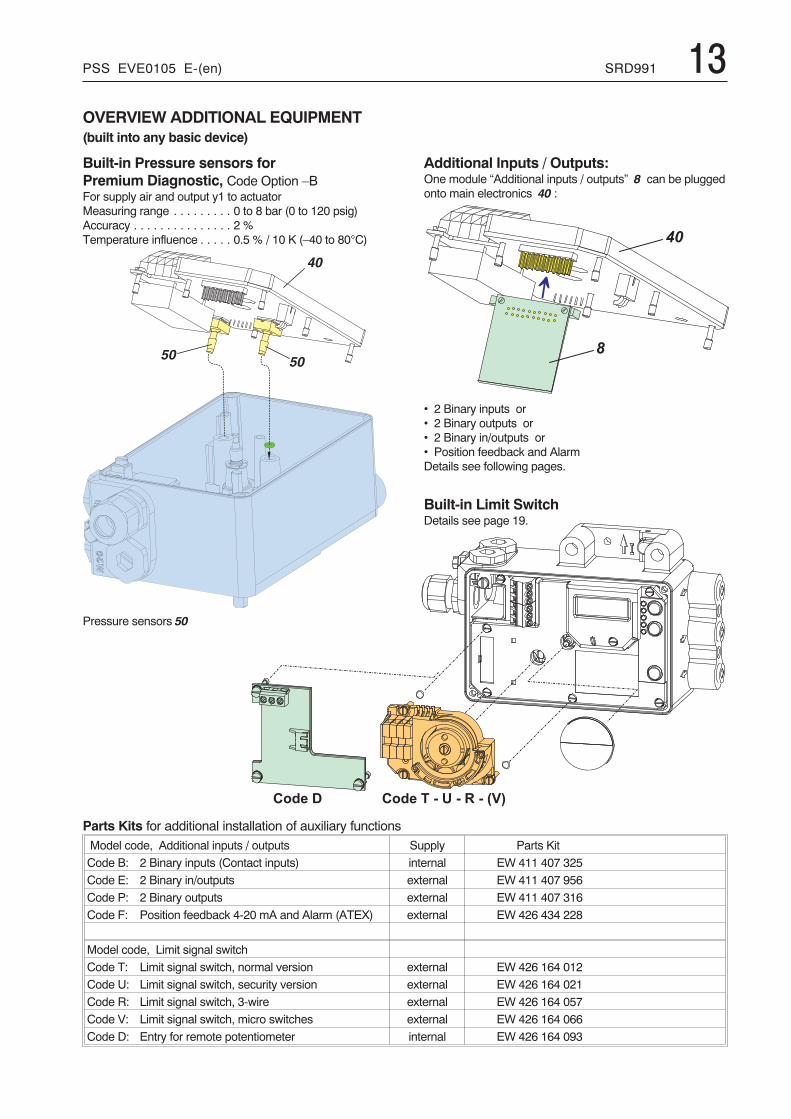
OVERVIEW ADDITIONAL EQUIPMENT(built into any basic device)
Built-in Pressure sensors forPremium Diagnostic, Code Option –BFor supply air and output y1 to actuatorMeasuring range . . . . . . . . . 0 to 8 bar (0 to 120 psig)Accuracy . . . . . . . . . . . . . . . 2 %Temperature influence . . . . . 0.5 % / 10 K (–40 to 80°C)
Pressure sensors 50
Additional Inputs / Outputs:One module “Additional inputs / outputs” 8 can be pluggedonto main electronics 40 :
• 2 Binary inputs or• 2 Binary outputs or• 2 Binary in/outputs or• Position feedback and AlarmDetails see following pages.
Built-in Limit SwitchDetails see page 19.
Parts Kits for additional installation of auxiliary functionsModel code, Additional inputs / outputs Supply Parts Kit
Code B: 2 Binary inputs (Contact inputs) internal EW 411 407 325
Code E: 2 Binary in/outputs external EW 411 407 956
Code P: 2 Binary outputs external EW 411 407 316
Code F: Position feedback 4-20 mA and Alarm (ATEX) external EW 426 434 228
Model code, Limit signal switch
Code T: Limit signal switch, normal version external EW 426 164 012
Code U: Limit signal switch, security version external EW 426 164 021
Code R: Limit signal switch, 3-wire external EW 426 164 057
Code V: Limit signal switch, micro switches external EW 426 164 066
Code D: Entry for remote potentiometer internal EW 426 164 093
14 SRD991 PSS EVE0105 E-(en)
ADDITIONAL EQUIPMENT built into any basic device
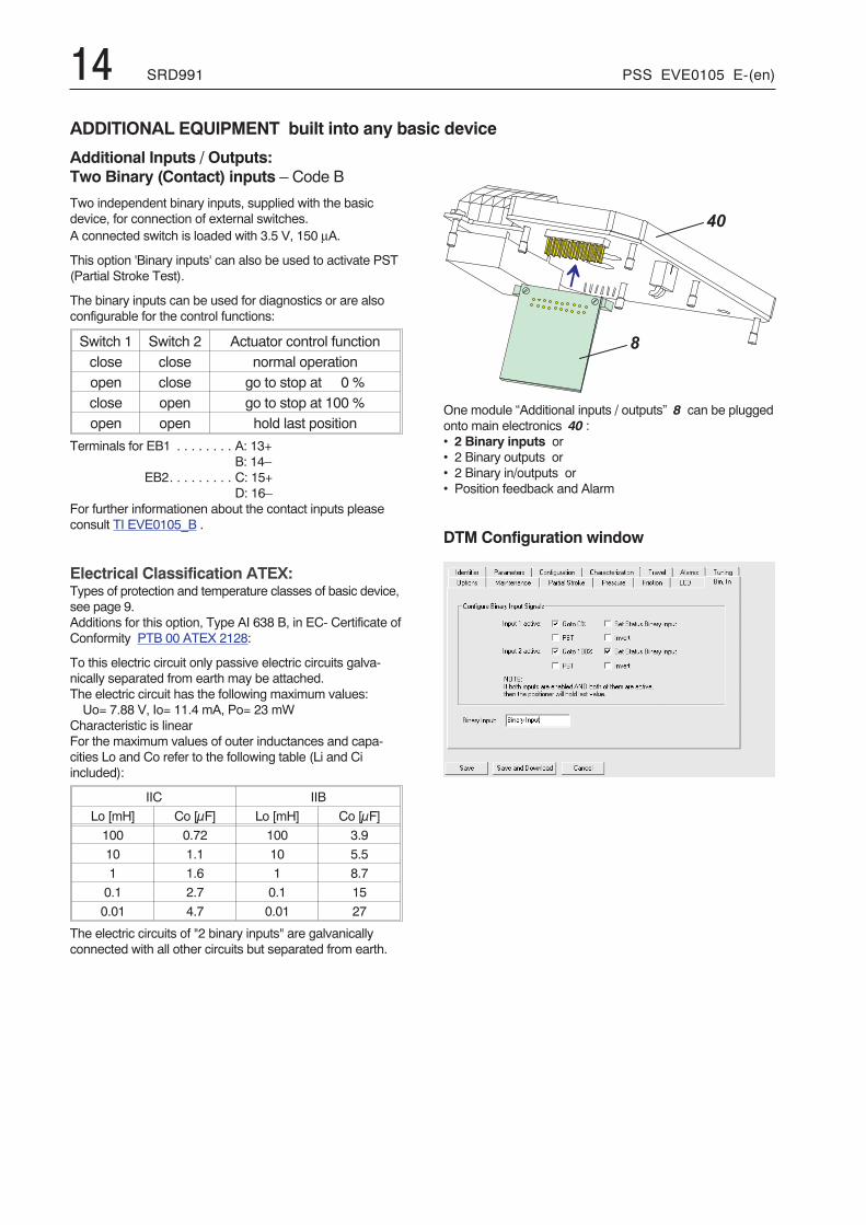
Additional Inputs / Outputs:Two Binary (Contact) inputs – Code B
Two independent binary inputs, supplied with the basicdevice, for connection of external switches.A connected switch is loaded with 3.5 V, 150 μA.
This option 'Binary inputs' can also be used to activate PST(Partial Stroke Test).
The binary inputs can be used for diagnostics or are alsoconfigurable for the control functions:
Switch 1 Switch 2 Actuator control functionclose close normal operationopen close go to stop at 0 %close open go to stop at 100 %open open hold last position
Terminals for EB1 . . . . . . . . A: 13+B: 14–
EB2. . . . . . . . . C: 15+D: 16–
For further informationen about the contact inputs pleaseconsult TI EVE0105_B .
Electrical Classification ATEX:Types of protection and temperature classes of basic device,see page 9.Additions for this option, Type AI 638 B, in EC- Certificate ofConformity PTB 00 ATEX 2128:
To this electric circuit only passive electric circuits galva-nically separated from earth may be attached.The electric circuit has the following maximum values:Uo= 7.88 V, Io= 11.4 mA, Po= 23 mW
Characteristic is linearFor the maximum values of outer inductances and capa-cities Lo and Co refer to the following table (Li and Ciincluded):
IIC IIB
Lo [mH] Co [μF] Lo [mH] Co [μF]
100 0.72 100 3.9
10 1.1 10 5.5
1 1.6 1 8.7
0.1 2.7 0.1 15
0.01 4.7 0.01 27
The electric circuits of "2 binary inputs" are galvanicallyconnected with all other circuits but separated from earth.
One module “Additional inputs / outputs” 8 can be pluggedonto main electronics 40 :• 2 Binary inputs or• 2 Binary outputs or• 2 Binary in/outputs or• Position feedback and Alarm
DTM Configuration window
�
� �
PSS EVE0105 E-(en) SRD991 15
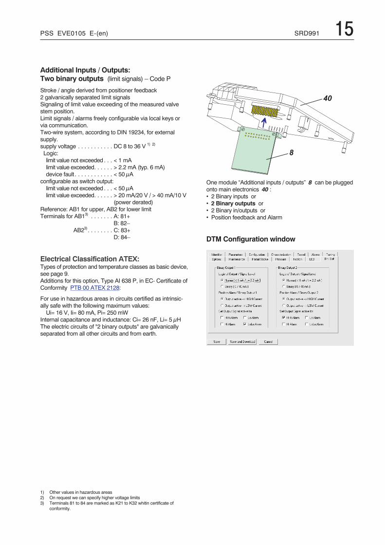
Additional Inputs / Outputs:Two binary outputs (limit signals) – Code P
Stroke / angle derived from positioner feedback2 galvanically separated limit signalsSignaling of limit value exceeding of the measured valvestem position.Limit signals / alarms freely configurable via local keys orvia communication.Two-wire system, according to DIN 19234, for externalsupply.supply voltage . . . . . . . . . . . DC 8 to 36 V 1) 2)
Logic:limit value not exceeded . . . < 1 mAlimit value exceeded. . . . . . > 2.2 mA (typ. 6 mA)device fault . . . . . . . . . . . . < 50 μA
configurable as switch output:limit value not exceeded . . . < 50 μAlimit value exceeded. . . . . . > 20 mA/20 V / > 40 mA/10 V
(power derated)Reference: AB1 for upper, AB2 for lower limitTerminals for AB13) . . . . . . . A: 81+
B: 82–AB23). . . . . . . . C: 83+
D: 84–
Electrical Classification ATEX:Types of protection and temperature classes as basic device,see page 9.Additions for this option, Type AI 638 P, in EC- Certificate ofConformity PTB 00 ATEX 2128:
For use in hazardous areas in circuits certified as intrinsic-ally safe with the following maximum values:Ui= 16 V, Ii= 80 mA, Pi= 250 mW
Internal capacitance and inductance: Ci= 26 nF, Li= 5 μHThe electric circuits of "2 binary outputs" are galvanicallyseparated from all other circuits and from earth.
1) Other values in hazardous areas2) On request we can specify higher voltage limits3) Terminals 81 to 84 are marked as K21 to K32 whitin certificate of
conformity.
One module “Additional inputs / outputs” 8 can be pluggedonto main electronics 40 :• 2 Binary inputs or• 2 Binary outputs or• 2 Binary in/outputs or• Position feedback and Alarm
DTM Configuration window
�
� �
16 SRD991 PSS EVE0105 E-(en)
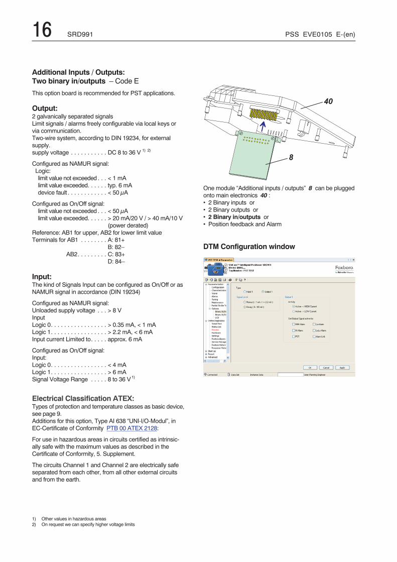
Additional Inputs / Outputs:Two binary in/outputs – Code E
This option board is recommended for PST applications.
Output:2 galvanically separated signalsLimit signals / alarms freely configurable via local keys orvia communication.Two-wire system, according to DIN 19234, for externalsupply.supply voltage . . . . . . . . . . . DC 8 to 36 V 1) 2)
Configured as NAMUR signal:Logic:limit value not exceeded . . . < 1 mAlimit value exceeded. . . . . . typ. 6 mAdevice fault . . . . . . . . . . . . < 50 μA
Configured as On/Off signal:limit value not exceeded . . . < 50 μAlimit value exceeded. . . . . . > 20 mA/20 V / > 40 mA/10 V
(power derated)Reference: AB1 for upper, AB2 for lower limit valueTerminals for AB1 . . . . . . . . A: 81+
B: 82–AB2. . . . . . . . . C: 83+
D: 84–
Input:The kind of Signals Input can be configured as On/Off or asNAMUR signal in accordance (DIN 19234)
Configured as NAMUR signal:Unloaded supply voltage . . . > 8 VInputLogic 0. . . . . . . . . . . . . . . . . > 0.35 mA, < 1 mALogic 1. . . . . . . . . . . . . . . . . > 2.2 mA, < 6 mAInput current Limited to. . . . . approx. 6 mA
Configured as On/Off signal:Input:Logic 0. . . . . . . . . . . . . . . . . < 4 mALogic 1. . . . . . . . . . . . . . . . . > 6 mASignal Voltage Range . . . . . 8 to 36 V1)
Electrical Classification ATEX:Types of protection and temperature classes as basic device,see page 9.Additions for this option, Type AI 638 “UNI-I/O-Modul”, inEC-Certificate of Conformity PTB 00 ATEX 2128:
For use in hazardous areas in circuits certified as intrinsic-ally safe with the maximum values as described in theCertificate of Conformity, 5. Supplement.
The circuits Channel 1 and Channel 2 are electrically safeseparated from each other, from all other external circuitsand from the earth.
1) Other values in hazardous areas2) On request we can specify higher voltage limits
One module “Additional inputs / outputs” 8 can be pluggedonto main electronics 40 :• 2 Binary inputs or• 2 Binary outputs or• 2 Binary in/outputs or• Position feedback and Alarm
DTM Configuration window
�
� �
PSS EVE0105 E-(en) SRD991 17
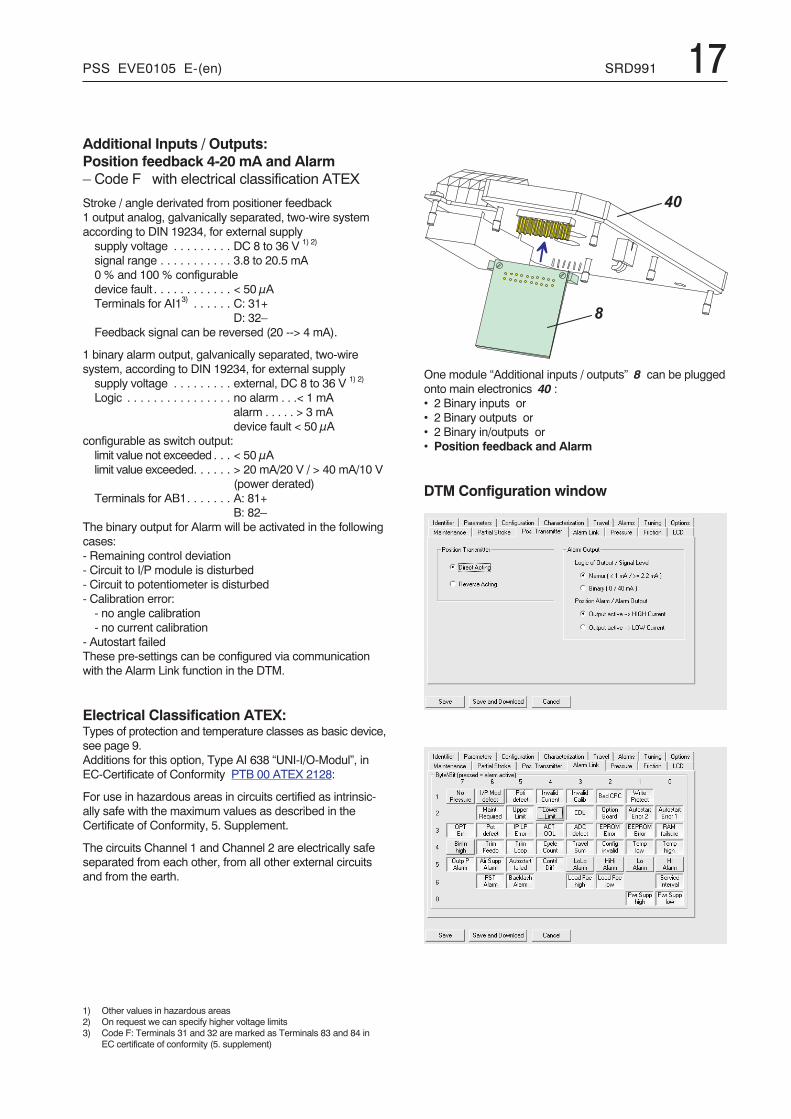
Additional Inputs / Outputs:Position feedback 4-20 mA and Alarm– Code F with electrical classification ATEX
Stroke / angle derivated from positioner feedback1 output analog, galvanically separated, two-wire systemaccording to DIN 19234, for external supplysupply voltage . . . . . . . . . DC 8 to 36 V 1) 2)
signal range . . . . . . . . . . . 3.8 to 20.5 mA0 % and 100 % configurabledevice fault . . . . . . . . . . . . < 50 μATerminals for AI13) . . . . . . C: 31+
D: 32–Feedback signal can be reversed (20 --> 4 mA).
1 binary alarm output, galvanically separated, two-wiresystem, according to DIN 19234, for external supplysupply voltage . . . . . . . . . external, DC 8 to 36 V 1) 2)
Logic . . . . . . . . . . . . . . . . no alarm . . .< 1 mAalarm . . . . . > 3 mAdevice fault < 50 μA
configurable as switch output:limit value not exceeded . . . < 50 μAlimit value exceeded. . . . . . > 20 mA/20 V / > 40 mA/10 V
(power derated)Terminals for AB1. . . . . . . A: 81+
B: 82–The binary output for Alarm will be activated in the followingcases:- Remaining control deviation- Circuit to I/P module is disturbed- Circuit to potentiometer is disturbed- Calibration error:- no angle calibration- no current calibration
- Autostart failedThese pre-settings can be configured via communicationwith the Alarm Link function in the DTM.
Electrical Classification ATEX:Types of protection and temperature classes as basic device,see page 9.Additions for this option, Type AI 638 “UNI-I/O-Modul”, inEC-Certificate of Conformity PTB 00 ATEX 2128:
For use in hazardous areas in circuits certified as intrinsic-ally safe with the maximum values as described in theCertificate of Conformity, 5. Supplement.
The circuits Channel 1 and Channel 2 are electrically safeseparated from each other, from all other external circuitsand from the earth.
1) Other values in hazardous areas2) On request we can specify higher voltage limits3) Code F: Terminals 31 and 32 are marked as Terminals 83 and 84 in
EC certificate of conformity (5. supplement)
One module “Additional inputs / outputs” 8 can be pluggedonto main electronics 40 :• 2 Binary inputs or• 2 Binary outputs or• 2 Binary in/outputs or• Position feedback and Alarm
DTM Configuration window
�
� �
�
�
� �
� �
�
� �
� � � � � � � � � � � � � �
� � � � � � � � � � �
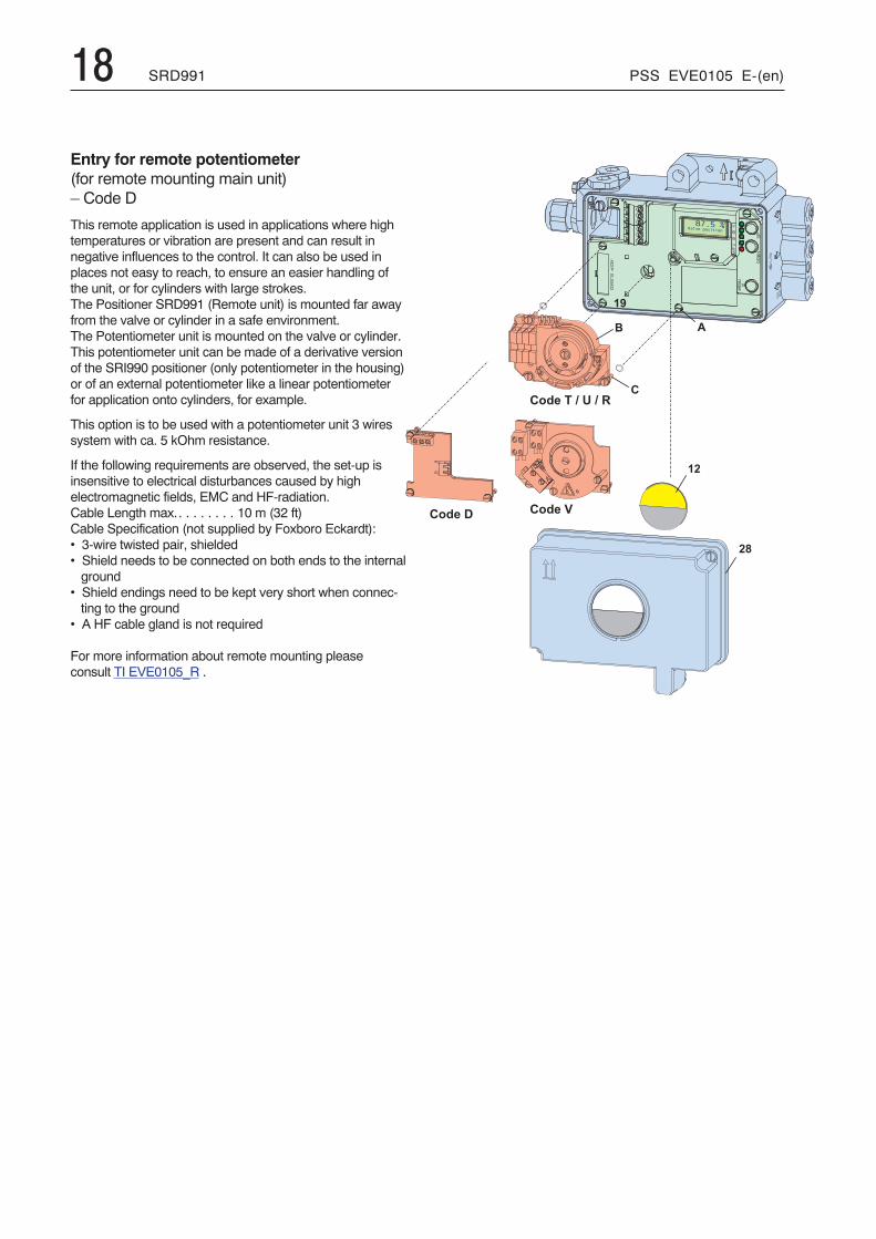
Entry for remote potentiometer(for remote mounting main unit)– Code D
This remote application is used in applications where hightemperatures or vibration are present and can result innegative influences to the control. It can also be used inplaces not easy to reach, to ensure an easier handling ofthe unit, or for cylinders with large strokes.The Positioner SRD991 (Remote unit) is mounted far awayfrom the valve or cylinder in a safe environment.The Potentiometer unit is mounted on the valve or cylinder.This potentiometer unit can be made of a derivative versionof the SRI990 positioner (only potentiometer in the housing)or of an external potentiometer like a linear potentiometerfor application onto cylinders, for example.
This option is to be used with a potentiometer unit 3 wiressystem with ca. 5 kOhm resistance.
If the following requirements are observed, the set-up isinsensitive to electrical disturbances caused by highelectromagnetic fields, EMC and HF-radiation.Cable Length max.. . . . . . . . 10 m (32 ft)Cable Specification (not supplied by Foxboro Eckardt):• 3-wire twisted pair, shielded• Shield needs to be connected on both ends to the internalground
• Shield endings need to be kept very short when connec-ting to the ground
• A HF cable gland is not required
For more information about remote mounting pleaseconsult TI EVE0105_R .
18 SRD991 PSS EVE0105 E-(en)
PSS EVE0105 E-(en) SRD991 19
�
�
� �
� �
�
� �
� � � � � � � � � � � � � �
� � � � � � � � � � �
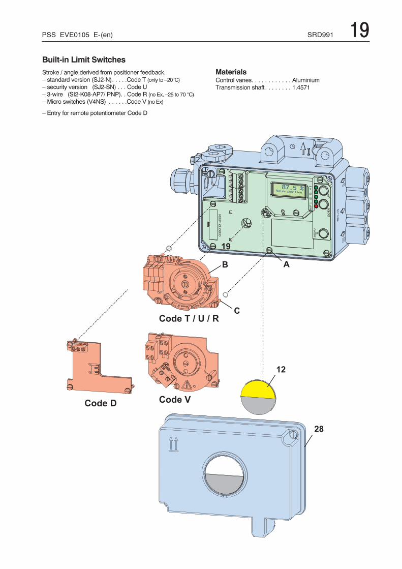
Built-in Limit SwitchesStroke / angle derived from positioner feedback.– standard version (SJ2-N). . . . .Code T (only to –20°C)– security version (SJ2-SN) . . . Code U– 3-wire (SI2-K08-AP7/ PNP). . Code R (no Ex, –25 to 70 °C)– Micro switches (V4NS) . . . . . .Code V (no Ex)
– Entry for remote potentiometer Code D
MaterialsControl vanes. . . . . . . . . . . . AluminiumTransmission shaft . . . . . . . . 1.4571
20 SRD991 PSS EVE0105 E-(en)
Inductive Limit Switch (Code T, U)Output . . . . . . . . . . . . . . . . . 2 inductive proximity sensorsacc. to DIN 19 234 or NAMUR for connection toswitching amplifier 1)
Current consumptionvane clear . . . . . . . . . . . . > 2.2 mAvane interposed . . . . . . . . < 1 mA
for control circuit with the following electrical values:supply voltage . . . . . . . . . DC 8 V, Ri approx. 1 kOhmsupply voltage range. . . . . DC 5 to 25 V (with "no Ex")residual ripple . . . . . . . . . . < 10 % p.p.permissibleline resistance . . . . . . . . . < 100 Ohms
Response characteristic 2) 3)
switching differential . . . . . < 1 %switching point repeatability < 0.2 %
Terminals for GW1. . . . . . . . 41+, 42–GW2 . . . . . . . . 51+, 52–
Electrical Classification ATEXof versions "T" and "U":Types of protection and temperature classes as basic device,see page 9.Additions for this option, Type AI 638 K, in EC- Certificate ofConformity PTB 00 ATEX 2128:
Types of protection and temperature classes as basic device.For use in hazardous areas in circuits certified as Intrinsic-ally Safe with the following maximum values:Ui= 16 V, Ii= 25 mA, Pi= 64 mW
Internal capacitance and inductance: Ci= 30 nF, Li= 100 μHThe electric circuits of "Built-in Limit Switch" are galvanicallyseparated from all other circuits and from earth.
Inductive Limit Switch, three-wire system– Code RInput . . . . . . . . . . . . . . . . . . Stroke / angle from actuator
via positioner feedback leverOutput . . . . . . . . . . . . . . . . . 2 inductive proximity sensors,
three-wire system,LED indication,contact, pnp 2)
Supply voltage US . . . . . . . . DC 10 to 30 VResidual ripple . . . . . . . . . . . ± 10 %, Us = 30 VSwitching frequency . . . . . . . 2 kHzConstant current . . . . . . . . . 100 mAResponse characteristic 6)
Gain . . . . . . . . . . . . . . . . . continuously adjustablefrom 1:1 to approx. 7:1
Switching differential . . . . . < 1 %Switching pointrepeatability. . . . . . . . . . . . < 0.2 %
Terminals for GW1. . . . . . . . 42GW2 . . . . . . . . 52Supply. . . . . . . 41+, 43–
1) Operating mode min. (= low) / max. (= high)selectable by adjustment of switch vanes
2) Data measured according to VDI/VDE 21773) With stroke 30 mm and lever length 90 mm
Mechanical Switches (Micro Switches) Code V(only without Ex protection)Stroke / angle derived from positioner feedback lever
Output . . . . . . . . . . . . . . . . . 2 mechanical switches (Microswitches)5) 6)
Manufacturer . . . . . . . . . . . . Saia-BurgessType . . . . . . . . . . . . . . . . . . V4NS-C4-AC1-UL
(UL- and CSA-approved)
Parts set for subsequent mounting:Code V . . . . . . . . . . . . . . . . EW 426 164 066
Absolute limit values ACof mechanical switches built into positioner:Umax. . . . . . . . . . . . . . . . . . 130 V AC 7)
Imax . . . . . . . . . . . . . . . . . . 0.5 A (resistive Load) 7)
Imax . . . . . . . . . . . . . . . . . . 0.03 A (inductive Load) 8)
Absolute limit values DCof mechanical switches built into positioner: 9)
Umax. . . . . . . . . . . . . . . . . . 30 V DCImax . . . . . . . . . . . . . . . . . . 1 A
Switching Differential: . . . . . . < 2.5 %Terminals for SW1 . . . . . . . . 41, 42
SW2. . . . . . . . 51, 52
The circuit of the mechanical switches have to be protectedby a suitable fuse. The diameter of the protective conductorneeds to be at least 1.5 mm² / AWG 16.
Input for Remote Potentiometer (code D)This option is necessary when the positioner is not mounteddirectly onto the valve but far away of it. In this case apotentiometer with 3 wires must be mounted onto the valveto give the valve position to the controller.
Remote potentiometer type to use in connection to this option:Resistance of 5 kOhm up to 10 kOhm(for other value of resistance please consult us).
If the following requirements are observed, the set-up isinsensitive to electrical disturbances caused by highelectromagnetic fields, EMC and HF-radiation.Cable length max. . . . . . . . . 10 m (32 ft)Cable specification (not supplied by Foxboro Eckardt):• 3-wire twisted pair, shielded• Shield needs to be connected on both ends to the internalground
• Shield endings need to be kept very short when connec-ting to the ground
• A HF cable gland is not required
For more information about remote mounting pleaseconsult TI EVE0105_R .
5) Operating mode min. (=low) / max. (=high) selectable by adjusting therespective vane
6) Operating mode normally open / normally closed selectable by vaneadjustment
7) Approval according to UL (UL 1054) and CSA (CSA 22.2 No. 55) at6,000 operations and T = 65 °C / 149 °F
8) Based on EN 61058-1, at 10,000 operations and T = 85 °C / 185 °F9) General rating at 50,000 operations and T = 85 °C / 185 °F
PSS EVE0105 E-(en) SRD991 21� � �
� � � �� �
� �
�
�
�
�
�
� �
�
�
� �
� �
� �
�
� �
�� �
� �
� �
�
� � � � �
� �
� �
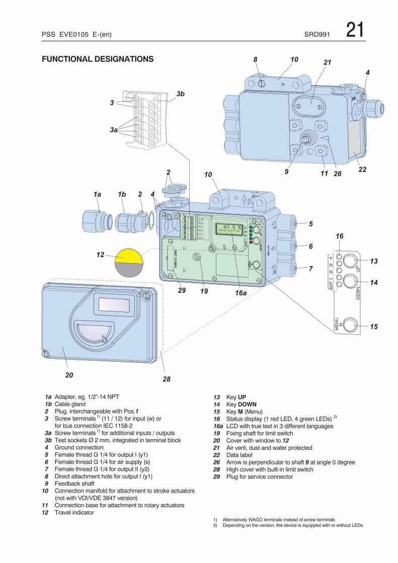
1) Alternatively WAGO terminals instead of screw terminals2) Depending on the version, the device is equipped with or without LEDs
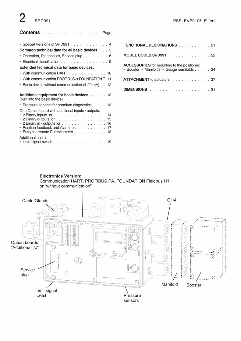
FUNCTIONAL DESIGNATIONS
1a Adapter, eg. 1/2”-14 NPT1b Cable gland2 Plug, interchangeable with Pos.13 Screw terminals 1) (11 / 12) for input (w) or
for bus connection IEC 1158-23a Screw terminals 1) for additional inputs / outputs3b Test sockets Ø 2 mm, integrated in terminal block4 Ground connection5 Female thread G 1/4 for output I (y1)6 Female thread G 1/4 for air supply (s)7 Female thread G 1/4 for output II (y2)8 Direct attachment hole for output I (y1)9 Feedback shaft10 Connection manifold for attachment to stroke actuators
(not with VDI/VDE 3847 version)11 Connection base for attachment to rotary actuators12 Travel indicator
13 Key UP14 Key DOWN15 KeyM (Menu)16 Status display (1 red LED, 4 green LEDs) 2)
16a LCD with true text in 3 different languages19 Fixing shaft for limit switch20 Cover with window to 1221 Air vent, dust and water protected22 Data label26 Arrow is perpendicular to shaft 9 at angle 0 degree28 High cover with built-in limit switch29 Plug for service connector
22 SRD991 PSS EVE0105 E-(en)
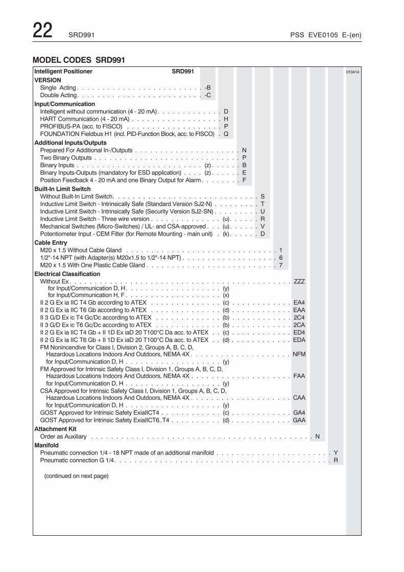
MODEL CODES SRD991Intelligent Positioner SRD991 010414
VERSIONSingle Acting . . . . . . . . . . . . . . . . . . . . . . . . . -BDouble Acting. . . . . . . . . . . . . . . . . . . . . . . . . -C
Input/CommunicationIntelligent without communication (4 - 20 mA). . . . . . . . . . . . . DHART Communication (4 - 20 mA) . . . . . . . . . . . . . . . . . . HPROFIBUS-PA (acc. to FISCO) . . . . . . . . . . . . . . . . . . . PFOUNDATION Fieldbus H1 (incl. PID-Function Block, acc. to FISCO) . Q
Additional Inputs/OutputsPrepared For Additional In-/Outputs . . . . . . . . . . . . . . . . . . . . . NTwo Binary Outputs . . . . . . . . . . . . . . . . . . . . . . . . . . . . . PBinary Inputs . . . . . . . . . . . . . . . . . . . . . . . . . (z). . . . . . BBinary Inputs-Outputs (mandatory for ESD application) . . . . (z). . . . . . EPosition Feedback 4 - 20 mA and one Binary Output for Alarm. . . . . . . . F
Built-In Limit SwitchWithout Built-In Limit Switch. . . . . . . . . . . . . . . . . . . . . . . . . . . . . SInductive Limit Switch - Intrinsically Safe (Standard Version SJ2-N) . . . . . . . . . TInductive Limit Switch - Intrinsically Safe (Security Version SJ2-SN) . . . . . . . . . UInductive Limit Switch - Three wire version . . . . . . . . . . . . . . (u). . . . . . RMechanical Switches (Micro-Switches) / UL- and CSA-approved . . . (u). . . . . . VPotentiometer Input - CEM Filter (for Remote Mounting - main unit) . (k). . . . . . D
Cable EntryM20 x 1.5 Without Cable Gland . . . . . . . . . . . . . . . . . . . . . . . . . . . . . . 11/2"-14 NPT (with Adapter(s) M20x1.5 to 1/2"-14 NPT) . . . . . . . . . . . . . . . . . . . 6M20 x 1.5 With One Plastic Cable Gland . . . . . . . . . . . . . . . . . . . . . . . . . . 7
Electrical ClassificationWithout Ex . . . . . . . . . . . . . . . . . . . . . . . . . . . . . . . . . . . . . . . . . . . . ZZZ
for Input/Communication D, H. . . . . . . . . . . . . . . . . . . (y)for Input/Communication H, F . . . . . . . . . . . . . . . . . . . (x)
II 2 G Ex ia IIC T4 Gb according to ATEX . . . . . . . . . . . . . . (c) . . . . . . . . . . . . EA4II 2 G Ex ia IIC T6 Gb according to ATEX . . . . . . . . . . . . . . (d) . . . . . . . . . . . . EAAII 3 G/D Ex ic T4 Gc/Dc according to ATEX . . . . . . . . . . . . . (b) . . . . . . . . . . . . 2C4II 3 G/D Ex ic T6 Gc/Dc according to ATEX . . . . . . . . . . . . . (b) . . . . . . . . . . . . 2CAII 2 G Ex ia IIC T4 Gb + II 1D Ex iaD 20 T100°C Da acc. to ATEX . . (c) . . . . . . . . . . . . ED4II 2 G Ex ia IIC T6 Gb + II 1D Ex iaD 20 T100°C Da acc. to ATEX . . (d) . . . . . . . . . . . . EDAFM Nonincendive for Class I, Division 2, Groups A, B, C, D,Hazardous Locations Indoors And Outdoors, NEMA 4X . . . . . . . . . . . . . . . . . . . . NFMfor Input/Communication D, H . . . . . . . . . . . . . . . . . . . (y)
FM Approved for Intrinsic Safety Class I, Division 1, Groups A, B, C, D,Hazardous Locations Indoors And Outdoors, NEMA 4X . . . . . . . . . . . . . . . . . . . . FAAfor Input/Communication D, H . . . . . . . . . . . . . . . . . . . (y)
CSA Approved for Intrinsic Safety Class I, Division 1, Groups A, B, C, D,Hazardous Locations Indoors And Outdoors, NEMA 4X . . . . . . . . . . . . . . . . . . . . CAAfor Input/Communication D, H . . . . . . . . . . . . . . . . . . . (y)
GOST Approved for Intrinsic Safety ExiaIICT4 . . . . . . . . . . . . (c) . . . . . . . . . . . . GA4GOST Approved for Intrinsic Safety ExiaIICT6..T4 . . . . . . . . . . (d) . . . . . . . . . . . . GAA
Attachment KitOrder as Auxiliary . . . . . . . . . . . . . . . . . . . . . . . . . . . . . . . . . . . . . . . . . . . . N
ManifoldPneumatic connection 1/4 - 18 NPT made of an additional manifold . . . . . . . . . . . . . . . . . . . . . . . YPneumatic connection G 1/4. . . . . . . . . . . . . . . . . . . . . . . . . . . . . . . . . . . . . . . . . . . R
(continued on next page)
PSS EVE0105 E-(en) SRD991 23MODEL CODES SRD991 (continued)
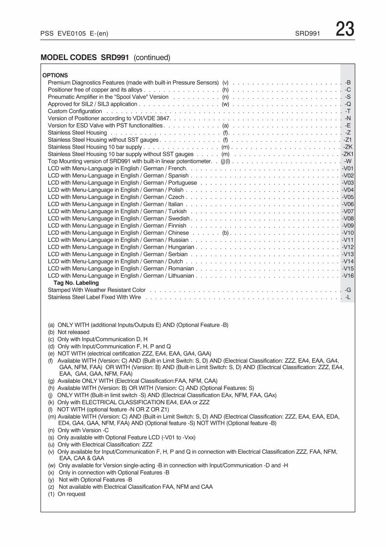
OPTIONSPremium Diagnostics Features (made with built-in Pressure Sensors) (v) . . . . . . . . . . . . . . . . . . . . . . . -BPositioner free of copper and its alloys . . . . . . . . . . . . . . . . (h) . . . . . . . . . . . . . . . . . . . . . . . -CPneumatic Amplifier in the "Spool Valve" Version . . . . . . . . . . (n) . . . . . . . . . . . . . . . . . . . . . . . -SApproved for SIL2 / SIL3 application . . . . . . . . . . . . . . . . . (w) . . . . . . . . . . . . . . . . . . . . . . . -QCustom Configuration . . . . . . . . . . . . . . . . . . . . . . . . . . . . . . . . . . . . . . . . . . . . . . . . . -TVersion of Positioner according to VDI/VDE 3847. . . . . . . . . . . . . . . . . . . . . . . . . . . . . . . . . . . . -NVersion for ESD Valve with PST functionalities . . . . . . . . . . . . (a) . . . . . . . . . . . . . . . . . . . . . . . -EStainless Steel Housing . . . . . . . . . . . . . . . . . . . . . . . (f). . . . . . . . . . . . . . . . . . . . . . . . -ZStainless Steel Housing without SST gauges . . . . . . . . . . . . . (f) . . . . . . . . . . . . . . . . . . . . . . . -Z1Stainless Steel Housing 10 bar supply . . . . . . . . . . . . . . . . (m) . . . . . . . . . . . . . . . . . . . . . . . -ZKStainless Steel Housing 10 bar supply without SST gauges . . . . . (m) . . . . . . . . . . . . . . . . . . . . . . -ZK1Top Mounting version of SRD991 with built-in linear potentiometer. . (j)(l) . . . . . . . . . . . . . . . . . . . . . . . -WLCD with Menu-Language in English / German / French. . . . . . . . . . . . . . . . . . . . . . . . . . . . . . . . -V01LCD with Menu-Language in English / German / Spanish . . . . . . . . . . . . . . . . . . . . . . . . . . . . . . . -V02LCD with Menu-Language in English / German / Portuguese . . . . . . . . . . . . . . . . . . . . . . . . . . . . . -V03LCD with Menu-Language in English / German / Polish . . . . . . . . . . . . . . . . . . . . . . . . . . . . . . . . -V04LCD with Menu-Language in English / German / Czech . . . . . . . . . . . . . . . . . . . . . . . . . . . . . . . . -V05LCD with Menu-Language in English / German / Italian . . . . . . . . . . . . . . . . . . . . . . . . . . . . . . . . -V06LCD with Menu-Language in English / German / Turkish . . . . . . . . . . . . . . . . . . . . . . . . . . . . . . . -V07LCD with Menu-Language in English / German / Swedish . . . . . . . . . . . . . . . . . . . . . . . . . . . . . . . -V08LCD with Menu-Language in English / German / Finnish . . . . . . . . . . . . . . . . . . . . . . . . . . . . . . . -V09LCD with Menu-Language in English / German / Chinese . . . . . . (b) . . . . . . . . . . . . . . . . . . . . . . . -V10LCD with Menu-Language in English / German / Russian . . . . . . . . . . . . . . . . . . . . . . . . . . . . . . . -V11LCD with Menu-Language in English / German / Hungarian . . . . . . . . . . . . . . . . . . . . . . . . . . . . . . -V12LCD with Menu-Language in English / German / Serbian . . . . . . . . . . . . . . . . . . . . . . . . . . . . . . . -V13LCD with Menu-Language in English / German / Dutch . . . . . . . . . . . . . . . . . . . . . . . . . . . . . . . . -V14LCD with Menu-Language in English / German / Romanian . . . . . . . . . . . . . . . . . . . . . . . . . . . . . . -V15LCD with Menu-Language in English / German / Lithuanian . . . . . . . . . . . . . . . . . . . . . . . . . . . . . . -V16Tag No. Labeling
Stamped With Weather Resistant Color . . . . . . . . . . . . . . . . . . . . . . . . . . . . . . . . . . . . . . . . -GStainless Steel Label Fixed With Wire . . . . . . . . . . . . . . . . . . . . . . . . . . . . . . . . . . . . . . . . . -L
(a) ONLY WITH (additional Inputs/Outputs E) AND (Optional Feature -B)(b) Not released(c) Only with Input/Communication D, H(d) Only with Input/Communication F, H, P and Q(e) NOTWITH (electrical certification ZZZ, EA4, EAA, GA4, GAA)(f) Available WITH (Version: C) AND (Built-in Limit Switch: S, D) AND (Electrical Classification: ZZZ, EA4, EAA, GA4,
GAA, NFM, FAA) ORWITH (Version: B) AND (Built-in Limit Switch: S, D) AND (Electrical Classification: ZZZ, EA4,EAA, GA4, GAA, NFM, FAA)
(g) Available ONLY WITH (Electrical Classification:FAA, NFM, CAA)(h) Available WITH (Version: B) ORWITH (Version: C) AND (Optional Features: S)(j) ONLY WITH (Built-in limit switch -S) AND (Electrical Classification EAx, NFM, FAA, GAx)(k) Only with ELECTRICAL CLASSIFICATION EA4, EAA or ZZZ(l) NOT WITH (optional feature -N OR Z OR Z1)(m) Available WITH (Version: C) AND (Built-in Limit Switch: S, D) AND (Electrical Classification: ZZZ, EA4, EAA, EDA,
ED4, GA4, GAA, NFM, FAA) AND (Optional feature -S) NOTWITH (Optional feature -B)(n) Only with Version -C(s) Only available with Optional Feature LCD (-V01 to -Vxx)(u) Only with Electrical Classification: ZZZ(v) Only available for Input/Communication F, H, P and Q in connection with Electrical Classification ZZZ, FAA, NFM,
EAA, CAA & GAA(w) Only available for Version single-acting -B in connection with Input/Communication -D and -H(x) Only in connection with Optional Features -B(y) Not with Optional Features -B(z) Not available with Electrical Classification FAA, NFM and CAA(1) On request
24 SRD991 PSS EVE0105 E-(en)
- . / 0
�
.- . � 0
1 2 � � � �
1 2 � � � 3 � 4 " � �
1 2 � � � 3 � 4 " � �
. /
. �
�
�
. - . � 0
- . / 0
/ 2 � � � 3 � 4 " � �
.
�
1 2 � � � 3 � 4 " � �
. /
. �
�
� � � 4 5
� 6 6 2 1 6 2 � 7 � �
� / � 2 1 8 2 4 � � �
� � � 2 1 8 2 4 � � �
� 6 / 2 9 6 2 � 6 / � �
4 1 2 / 6 2 / 7 � �
� / � 2 1 8 2 4 � � �
�
�
�
�
�
�
�
�
�
� 2 � 2 � :
� 2 � 2 � :
� 2 � 2 � :
- � 2 � 2 � 0
� � � � � � � ! � � � � � � � " � # � � � ! � � $ �� � $ � � � � � � , � � %
� � � � � � � ! � � ! � � � ! � � # � � � ! � � $ �� � � � $ ' , � ' % � � & � $ � � � � ) � � � � � $ '
� � � � � � � ! � � % � � � � % � � # � � � ! � � $ �� � $ � � � � � � , � � % , � ' � � � � $ � � � � ) � � � � � $ '� � � ) ' $ � � � ' $ � � � � $ � , � ' � � ) ) � . � � ' � � % � � ) � .
� � � � � � � ! � � & � � � � & � � # � � � ! � � $ �� � $ � � � � � � , � � % , � ' % � � & � $ � � � � ) � � � � � $ '� � � ) ' $ � � � ' $ � � � � $ � , � ' � � ) ) � . � � ' � � � � ) � � . � � % . /
� � � � � � � ! � � ' � � � � ' � � # � � � ! � � $ �� � 3 + � 3 + � � & � � � � � � ) ' $ � � � ' $ � � � � $ �
5 � � $ % � ' $ � % � , � ' ) ' $ � � � ' $ � � � � $ � � ' $ � � � � $ % & . � $ � � � , � � � ; � � ' $ � � � ' " � < � / 7 6 / � 6 � 1 <
� � � � � � � ! � � & (! � % � � � � + � � , � � % � � � 1 � � � � $ � � & $ � � � $ % � � $ � $ ' � � � = � � � � $ & � � � $ ' . ) $ � > ? � 3 � 2 � ' = � ! / 6 �
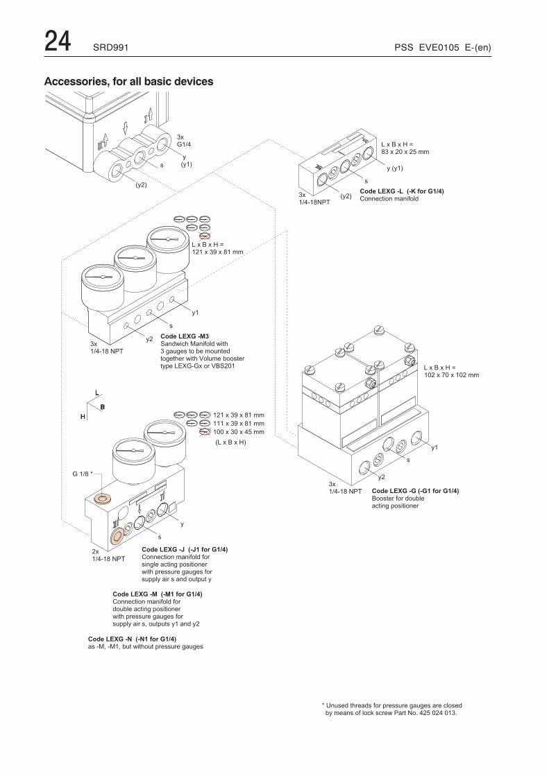
Accessories, for all basic devices
PSS EVE0105 E-(en) SRD991 25Model Codes AccessoriesAccessories for intelligent Positioners 010414
Filter RegulatorsFilter Regulator FRS923-2SK Filter Regulator for -40°C to 80°C. . . . . . . . . . . . . . . . . . . . . . . . FRS01Filter Regulator Filter Regulator for -20°C to 70°C . . . . . . . . . . . . . . . . . . . . . . . . . . . . . . . FRS02Filter Regulator Stainless Steel (316) Filter Regulator . . . . . . . . . . . . . . . . . . . . . . . . . . . . . FRS03Mounting Bracket for FRS02 or FRS03 . . . . . . . . . . . . . . . . . . . . . . . . . . . . . . . . . . . EBZG-FR1Orientable Mounting Bracket for FRS02 or FRS03 . . . . . . . . . . . . . . . . . . . . . . . . . . . . . EBZG-FR2Nipple for direct mounting Filter regulator 1/4 NPT both sides . . . . . . . . . . . . . . . . . . . . . . . . . VG-91
Communication/Modem/DTMHART USB Modem (made by Ifak) with ATEX IS Certification . . . . . . . . . . . . . . . . . . . . . . . . MOD900DTM for SRD Serie for HART / FF / Profibus / FoxCom . . . . . . . . . . . . . . . . . . . . . . . . . . . VALCAREATEX IS Barrier Rail Mounted Module, 1 Channel, ATEX EEx ia IIC / FM Intrinsically Safe (TV228-SEGX) . . TV228
Booster RelayBooster Cv1 - Alu Housing - Remote mount . . . . . . . . . . (f) . . . . . . . . . . . . . . . . . . . . . . VBS100Booster Cv1 - SST Housing - Remote mount . . . . . . . . . (g) . . . . . . . . . . . . . . . . . . . . . . VBS110Booster Cv3 - Alu Housing - Remote mount . . . . . . . . . (b) . . . . . . . . . . . . . . . . . . . . . . VBS300Booster Cv3 - SST Housing - Remote mount . . . . . . . . . (b) . . . . . . . . . . . . . . . . . . . . . . VBS310Booster Relay with connection 1/4-18 NPT. . . . . . . . . . . . . . . . . . . . . . . . . . . . . . . . . . LEXG-GBooster Relay with connection G 1/4 . . . . . . . . . . . . . . . . . . . . . . . . . . . . . . . . . . . . LEXG-G1
Surge/Lightning ProtectionSurge/Lightning Protection for 4-20 mA with or without HART type TP48-N-NDI . . . . . . . . . . . . . . . BUSG-L1Surge/Lightning Protection for FF/Profibus type TP32-N-NDI . . . . . . . . . . . . . . . . . . . . . . . . BUSG-L4
Lock-in RelaysLock-In Relay for lost of air-supply for single acting / NAMUR Mounting . . . . . . . . . . . . . . . . . . . LEXG-VR1Lock-In Relay (Fall Freeze) for lost of air-supply and electric power for single and double acting /SRI990 direct mounting . . . . . . . . . . . . . . . . . . . . . . . . . . . . . . . . . . . . . . . . . LEXG-VR6
Lock-In Relay for lost of air-supply for single and double acting / direct mounting . . . . . . . . . . . . . . LEXG-VR8
wirelessHART moduleWirelessHART Module Type Mactek BULLET for PST Monitoring (no Ex) . . . . . . . . . . . . . . . . . BUSG-WH1WirelessHART Module Type Mactek BULLET for PST Monitoring (Intrinsically Safe ATEX+FM) . . . . . . BUSG-WH2
Cable GlandCable Gland, M20x1.5 Plug-Connector For Fieldbus (ss/Threaded Connection 7/8 - UN)BUSG-F2�Cable Gland, M20x1.5 Plastics, Color Gray/Black . . . . . . . . . . . . . . . . . . . . . . . . . . . . . . BUSG-K6Cable Gland, M20x1.5 Plastics, Color Blue . . . . . . . . . . . . . . . . . . . . . . . . . . . . . . . . . BUSG-K7Cable Gland, M20x1.5 Plastics, Color White. . . . . . . . . . . . . . . . . . . . . . . . . . . . . . . . . BUSG-K9Cable Gland, M20x1.5 Plug-Connector For Fieldbus (ss/Threaded Connection M12) . . . . . . . . . . . . BUSG-P3Cable Gland, M20x1.5 HF For Fieldbus . . . . . . . . . . . . . . . . . . . . . . . . . . . . . . . . . . . BUSG-P4Cable Gland, M20x1.5 Stainless Steel. . . . . . . . . . . . . . . . . . . . . . . . . . . . . . . . . . . . BUSG-S6
Tube FittingsTube Fittings, G 1/4A, 6x1mm , 1 pc . . . . . . . . . . . . . . . . . . . . . . . . . . . . . . . . . . . . . VG-01Tube Fittings, G 1/4A, 6x1mm, 2 pc . . . . . . . . . . . . . . . . . . . . . . . . . . . . . . . . . . . . . . VG-02Tube Fittings, G 1/4A, 6x1mm, 3 pc . . . . . . . . . . . . . . . . . . . . . . . . . . . . . . . . . . . . . . VG-03Tube Fittings, 1/4 NPT, 6x1mm, 2 pc . . . . . . . . . . . . . . . . . . . . . . . . . . . . . . . . . . . . . VG-52Tube Fittings, 1/4 NPT, 6x1mm, 3 pc . . . . . . . . . . . . . . . . . . . . . . . . . . . . . . . . . . . . . VG-53
AdapterAdapter (Brass With Nickel Coating) M20 x 1.5 to 1/2 - 14 NPT (Internal Thread) . . . . . . . . . . . . . . . AD-A5Adapter (ss) M20x1.5 to 1/2-14 NPT (Internal Thread) . . . . . . . . . . . . . . . . . . . . . . . . . . . . AD-A6Adapter (ss) M20x1.5 to G 1/2" (Internal Thread) . . . . . . . . . . . . . . . . . . . . . . . . . . . . . . . AD-A8Adapter (Plastic) M20x1.5 to PG13.5 (Internal Thread) . . . . . . . . . . . . . . . . . . . . . . . . . . . . AD-A9
26 SRD991 PSS EVE0105 E-(en)
MODEL CODES Attachment kitsMODEL CODES Attachment kitsACCESSORIES FOR POSITIONER (SRD991, SRI990, SRD960) 012007
Attachment Kit EBZGFor diaphragm actuators with casting yoke acc. NAMUR (incl. standard Couple lever) . . . . . . . . . . . . . . . . . -HFor diaphragm actuators with pillar yoke acc. NAMUR (incl. standard Couple lever). . . . . . . . . . . . . . . . . . . -KFor directly mounting (incl. standard Couple lever) . . . . . . . . . . . . . . . . . . . . . . . . . . . . . . . . . . . -DFor mounting to rotary actuators acc. VDI/VDE 3845 (without bracket) . . . . . . . . . . . . . . . . . . . . . . . . . -RFor FoxTop / FoxPak . . . . . . . . . . . . . . . . . (g). . . . . . . . . . . . . . . . . . . . . . . . . . . . . . . -EBrackets VDI/VDE 3845 (A = 130 mm/5.12 in; B = 50 mm/1.97 in) . . . . . . . . . . . . . . . . . . . . . . . . . . . -C3Brackets VDI/VDE 3845 (A = 80 mm/3.15 in; B = 30 mm/1.18 in) . . . . . . . . . . . . . . . . . . . . . . . . . . . -C2Brackets VDI/VDE 3845 (A = 80 mm/3.15 in; B = 20 mm/0.79 in) . . . . . . . . . . . . . . . . . . . . . . . . . . . -C1For Badger Meter - Research Control Series 754 and 755 Size 1/2 inch . . . . . . . . . . . . . . . . . . . . . . . . -B1For Fisher 657, 667 (linear) size 30 and 40. . . . . . . . . . . . . . . . . . . . . . . . . . . . . . . . . . . . . . . -F1For Fisher 1051, 1052, 1061 size 40 . . . . . . . . . . . . . . . . . . . . . . . . . . . . . . . . . . . . . . . . . . -F2For Fisher 657, 667 size 30 and 60 . . . . . . . . . . . . . . . . . . . . . . . . . . . . . . . . . . . . . . . . . . -F3For Fisher 657, 667 size 70 and 100 . . . . . . . . . . . . . . . . . . . . . . . . . . . . . . . . . . . . . . . . . . -F4For Fisher 1051, 1052, 1061 size 33 . . . . . . . . . . . . . . . . . . . . . . . . . . . . . . . . . . . . . . . . . . -F5For Fisher 1051, 1052, 1061 size 60 . . . . . . . . . . . . . . . . . . . . . . . . . . . . . . . . . . . . . . . . . . -F6For Foxboro P-Series / such as -H with installed height 80 mm/3.15 in . . . . . . . . . . . . . . . . . . . . . . . . . -H1NAMUR-Attachment kit for centered mounting position on the casting yoke . . . . . . . . . . . . . . . . . . . . . . -H2For mounting on ADAR control valve . . . . . . . . . . . . . . . . . . . . . . . . . . . . . . . . . . . . . . . . . -H3For mounting on ADAR micro flow control valve . . . . (k) . . . . . . . . . . . . . . . . . . . . . . . . . . . . . . -H4Such as -K with installed height 80 mm/3.15 in) . . . . . . . . . . . . . . . . . . . . . . . . . . . . . . . . . . . . -K1For Kinetrol (Actuator Size 05) . . . . . . . . . . . . . . . . . . . . . . . . . . . . . . . . . . . . . . . . . . . . . -K2For Kinetrol (Actuator Size 07) . . . . . . . . . . . . . . . . . . . . . . . . . . . . . . . . . . . . . . . . . . . . . -K3For Kinetrol (Actuator Size 09) . . . . . . . . . . . . . . . . . . . . . . . . . . . . . . . . . . . . . . . . . . . . . -K4For Metso / Neles Rotary actuators Type AB6 and Type BJ & BC size 8 and 10, B1C11 . . . . . . . . . . . . . . . . -L1For Metso / Neles Rotary actuators Type BJ and BC size 12 and 16, B1C17 . . . . . . . . . . . . . . . . . . . . . . -L2For ARI-Armaturen - Direct Mounting to actuator type DR . . . . . . . . . . . . . . . . . . . . . . . . . . . . . . . -P1For ARCA - Direct Mounting to actuator type BR 812. . . . . . . . . . . . . . . . . . . . . . . . . . . . . . . . . . -P2For Samson Type 3277 with 1/4 - 18 NPT . . . . . . . . . . . . . . . . . . . . . . . . . . . . . . . . . . . . . . . -S1For Samson Type 3277 with G 1/4. . . . . . . . . . . . . . . . . . . . . . . . . . . . . . . . . . . . . . . . . . . -S2For Samson Type 3277 with 1/4 - 18 NPT and gauges for supply- and output-pressure . . (g) . . . . . . . . . . . . -S5For Samson Type 3277 with G 1/4 and gauges for supply- and output-pressure . . (g) . . . . . . . . . . . . . . . . -S6For Samson Micro flow Type 3277-5 . . . . . . . . . . . . . (k) . . . . . . . . . . . . . . . . . . . . . . . . . . . -S8Tuflin / XOMOX Type MX60 . . . . . . . . . . . . . . . . . (h) . . . . . . . . . . . . . . . . . . . . . . . . . . . -T1Tuflin / XOMOX Type MX200 . . . . . . . . . . . . . . . . . (h) . . . . . . . . . . . . . . . . . . . . . . . . . . . -T2Tuflin / XOMOX Type MX450 / Typ MX750 / Typ MX1250 . . (h) . . . . . . . . . . . . . . . . . . . . . . . . . . . -T3Tuflin / XOMOX Type MX3000 . . . . . . . . . . . . . . . . (h) . . . . . . . . . . . . . . . . . . . . . . . . . . . -T4For Hagan actuators (left of pneumatic cylinder) . . . . . . . . . . . . . . . . . . . . . . . . . . . . . . . . . . . . -X2For Hagan actuators (right of pneumatic cylinder) . . . . . . . . . . . . . . . . . . . . . . . . . . . . . . . . . . . -X1For AMRI rotary actuator (requires minor modification of actuator. Please consult ECKARDT production before ordering!) -X3For Siemens actuators V-Series . . . . . . . . . . . . . . . . . . . . . . . . . . . . . . . . . . . . . . . . . . . . -S3For Sereg Maxflo, Revca, Reglob new type . . . . . . . . . . . . . . . . . . . . . . . . . . . . . . . . . . . . . . -S4For Sereg Maxflo "old type" . . . . . . . . . . . . . . . . . . . . . . . . . . . . . . . . . . . . . . . . . . . . . . -S7For Sereg CNX (Flowserve) . . . . . . . . . . . . . . . . . . . . . . . . . . . . . . . . . . . . . . . . . . . . . . -S9For Masoneilan Type Camflex II . . . . . . . . . . . . . . . . . . . . . . . . . . . . . . . . . . . . . . . . . . . . -MFor Masoneilan 47/48 (Sigma-F). . . . . . . . . . . . . . . . . . . . . . . . . . . . . . . . . . . . . . . . . . . . -M1For Masoneilan Type 37/38 size 15 and 18 (complete kit) . . . . . . . . . . . . . . . . . . . . . . . . . . . . . . . -M2For Masoneilan Type 87/88 all size . . . . . . . . . . . . . . . . . . . . . . . . . . . . . . . . . . . . . . . . . . -M4For Masoneilan Varipac . . . . . . . . . . . . . . . . . . . . . . . . . . . . . . . . . . . . . . . . . . . . . . . . -M5For Masoneilan 37/38 size 9, 11, 13 . . . . . . . . . . . . . . . . . . . . . . . . . . . . . . . . . . . . . . . . . . -M6For Masoneilan / Severn Glocon Type Domotor size small . . (h). . . . . . . . . . . . . . . . . . . . . . . . . . . -M7For Valtek Linear Actuator all Sizes - Stroke up to 4 inch / 102 mm. . . . . . . . . . . . . . . . . . . . . . . . . . . -V1For VETEC Type R150 . . . . . . . . . . . . . . . . . . . . . . . . . . . . . . . . . . . . . . . . . . . . . . . . -V2
*) We recommend to contact our field service dept. before selection of these mounting kits.Further Attachment kits on request.
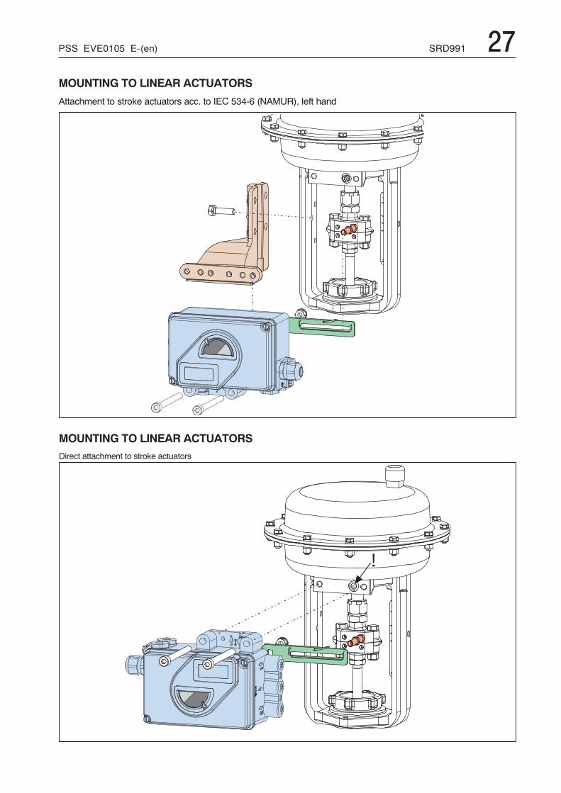
PSS EVE0105 E-(en) SRD991 27MOUNTING TO LINEAR ACTUATORS
Attachment to stroke actuators acc. to IEC 534-6 (NAMUR), left hand
MOUNTING TO LINEAR ACTUATORSDirect attachment to stroke actuators
28 SRD991 PSS EVE0105 E-(en)
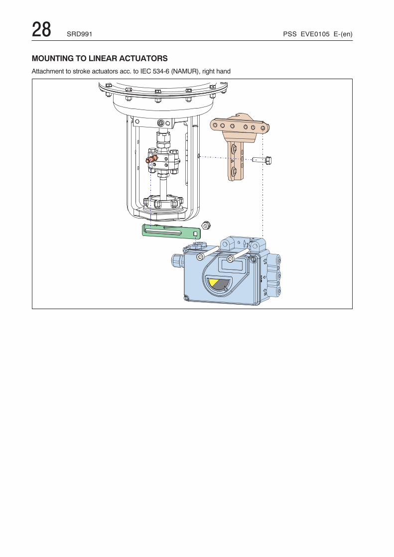
MOUNTING TO LINEAR ACTUATORS
Attachment to stroke actuators acc. to IEC 534-6 (NAMUR), right hand
PSS EVE0105 E-(en) SRD991 29
� �� ���
� �
� ��
� ���
� � �� �
�9
�1�7
� �
�
���
���
��
���� �
� �< 7 7
�
� � � � � �
���
4< 1 �
� � �� � �
mmin
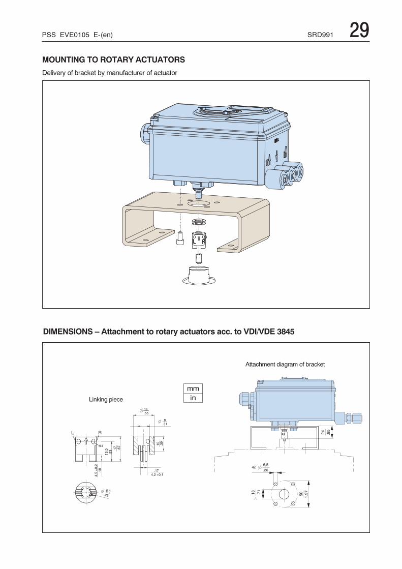
Attachment diagram of bracket
Linking piece
MOUNTING TO ROTARY ACTUATORS
Delivery of bracket by manufacturer of actuator
DIMENSIONS – Attachment to rotary actuators acc. to VDI/VDE 3845
30 SRD991 PSS EVE0105 E-(en)
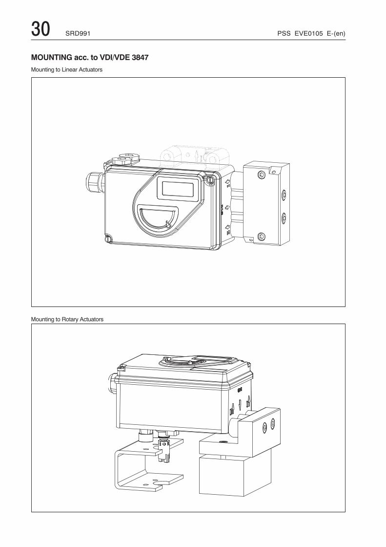
MOUNTING acc. to VDI/VDE 3847Mounting to Linear Actuators
Mounting to Rotary Actuators
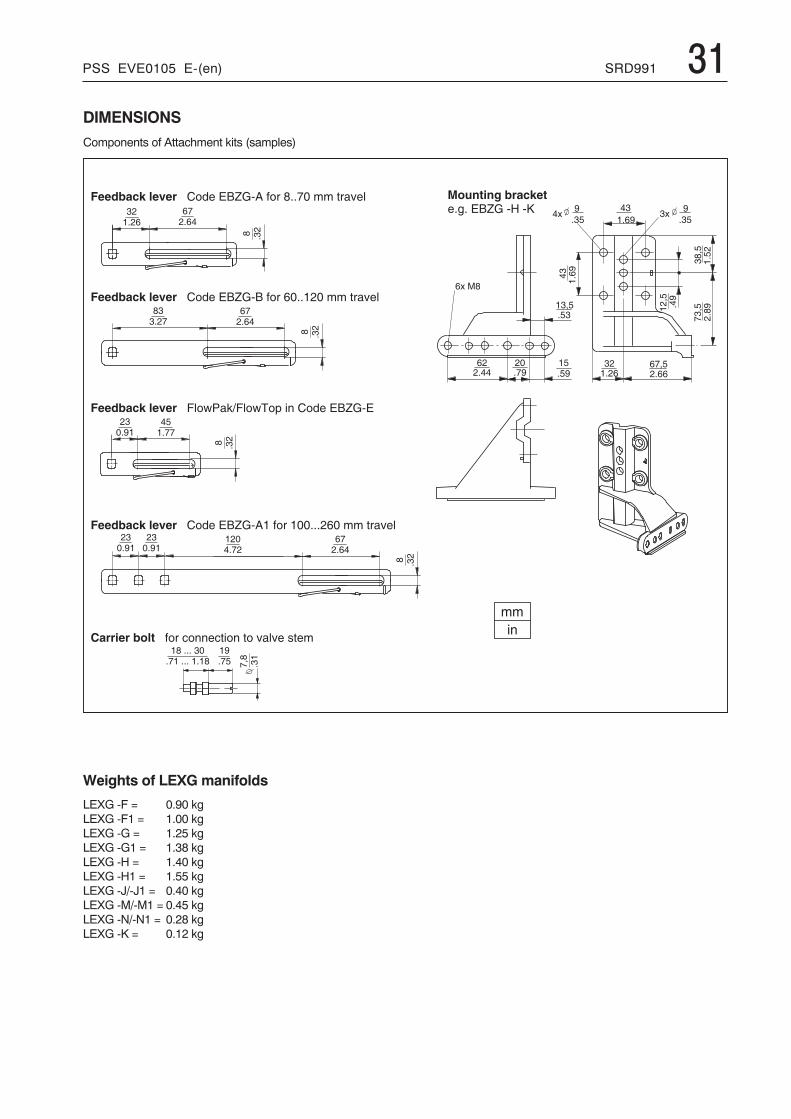
PSS EVE0105 E-(en) SRD991 31DIMENSIONSComponents of Attachment kits (samples)
� �� �
���
����
���
���
� � � � �
��
���
� � �� �
� � �� � �
� � � �� �� � � �
� � � � � � �
� �� � ��
�����
� � � � �
� �� � �
�� � �
��
��
�� � �
� � � � � � � � � � � � � � � �
� �� � � �
� ���
� �� � � �
� � � � �
� �� � � �
� ���
� ���
� � � �
� � � � �
� � � � �
� �� � � �
� ���
� � � �
� � � �
� � � � � � � � � � � � � � � � � � � � � � � � � � ! � " � � � � � � � � � # " $ % � &
� � � � � � � � � � � � � � � � � � � � � � � � � � � ! � " � � � � � � � � � # " $ % � &
� � � � � � � � � � � � ! � " � ' � � � � ' # � � � � # � � % $ & % � � ( # � �
� � � � � � � � � � � � � � �� � ) � � � � � � � � * � � +
� � � � � � � � � � � � � � � , & � - . $ / 0 , & � - 1 � 2 � � � � � � � � � � � � � � �
� � � � � � � � � � � � � � � � � � � � � � � � � � ! � " � � � � � � � � � � # " $ % � &
Weights of LEXG manifolds
LEXG -F = 0.90 kgLEXG -F1 = 1.00 kgLEXG -G = 1.25 kgLEXG -G1 = 1.38 kgLEXG -H = 1.40 kgLEXG -H1 = 1.55 kgLEXG -J/-J1 = 0.40 kgLEXG -M/-M1 = 0.45 kgLEXG -N/-N1 = 0.28 kgLEXG -K = 0.12 kg
32 SRD991 PSS EVE0105 E-(en)
<18
�7
<78
�</
��65
�<115
81
1<@@
16
�<�4
16
�<�4
16
�<�4
+ 4 2 � 6
�7
<78
+ 4 2 < 1 8 % $ $ )/ 2
� � 9
� < @ �
� 9 @
@ < 8 �
�/��1
�<94
4
<1�
� �
< 7 7
@ /
/ < � �
� 8
< 9 7
4 � �
< 1 1
76
�<89
91
/<49
+ @ 2 � 6
+ @ 2 < 1 8 % $ $ )� 2
/ 2
�1
<7�
�6
16�@
� �
�
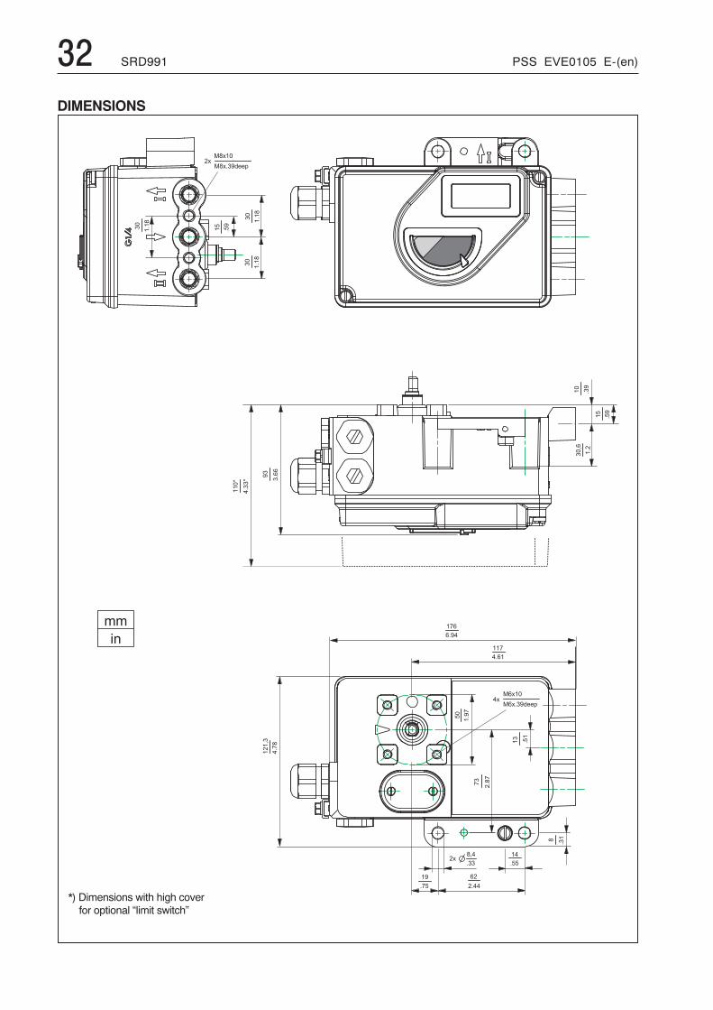
*) Dimensions with high coverfor optional “limit switch”
DIMENSIONS
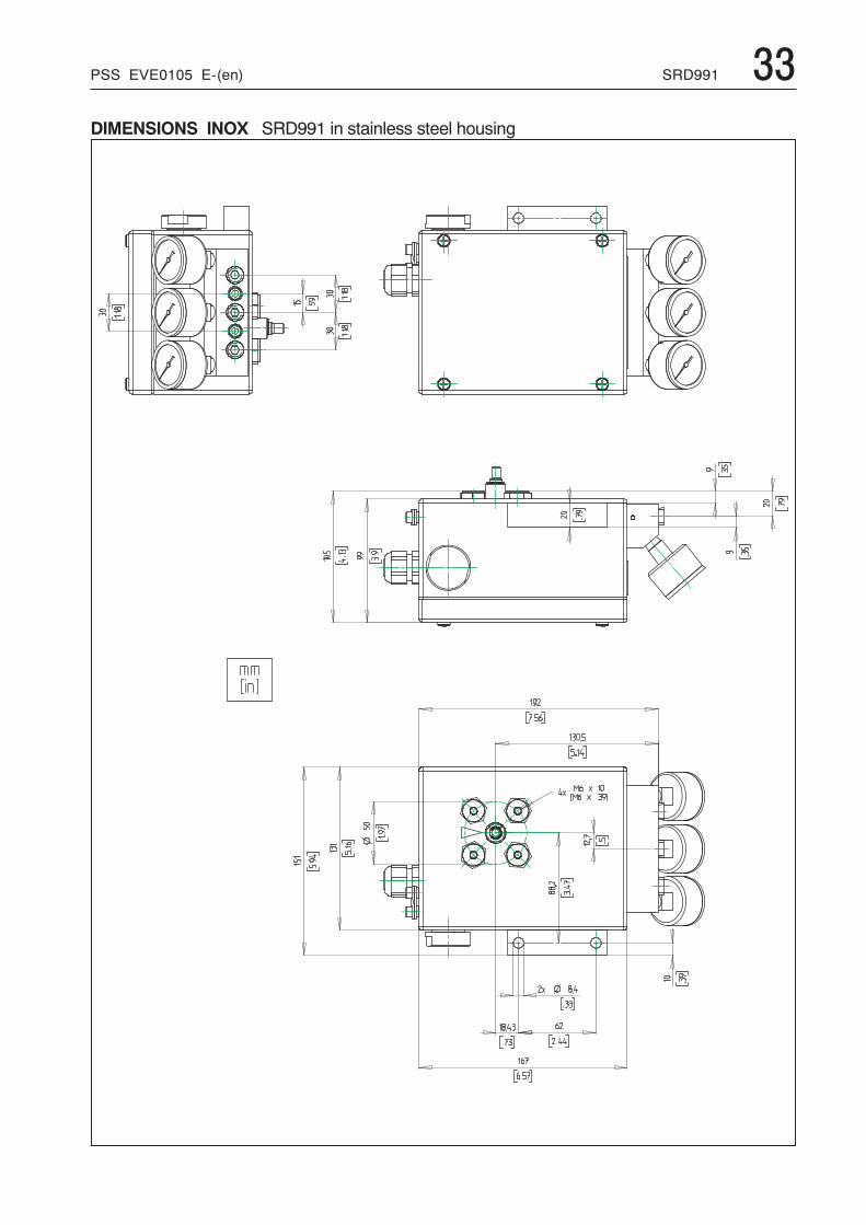
PSS EVE0105 E-(en) SRD991 33DIMENSIONS INOX SRD991 in stainless steel housing
34 SRD991 PSS EVE0105 E-(en)
Subject to alterations - reprinting, copying and translation prohibited. Products and publications are normally quotedhere without reference to existing patents, registered utility models or trademarks. The lack of any such referencedoes not justify the assumption that a product or symbol is free.
FOXBOROECKARDTGmbH ECKARDTS.A.S. DOKT534 022 074Pragstr. 82 20 rue de la MarneD-70376 Stuttgart F-68360 SoultzGermany FranceTel. +49 (0)711 502-0 Tel. + 33 (0)3 89 62 15 30Fax +49 (0)711 502-597 Fax + 33 (0)3 89 62 14 85http://www.foxboro-eckardt.com
Additional Documentation for this productTechnical Information of Attachment Kits for PositionersTI EVE0011 A Overview of Attachment Kits of all positioners on actuators/valves of different manufacturersQuick GuideQG EVE0105 B Extract of Master Instruction for an easy to use, easy understandable and fast start-up.
This document highlights the most important aspects.Master InstructionsMI EVE0105 E SRD991 – all versions –Technical Information for Fieldbus-CommunicationTI EVE0105 H SRD991/960 -HARTTI EVE0105 P SRD991/960 -PROFIBUS-PATI EVE0105 Q SRD991/960 -FOUNDATION Fieldbus H1Master Instruction for HART Hand-Held TerminalMI EVE0105 B HART with Hand-Held TerminalTechnical InformationTI EVE0102 U Upgrade KitsTI EVE0105 S SIL Functional safetyTI EVE0305 MUX Use of HART MultiplexerValvediagnostic-, configuration- andoperation-softwareVALcare™MI EVE0501 V VALcare Valve diagnostic for Positioners
HART/ PROFIBUS-PA, and FOUNDATION Fieldbus
Additional Documentation for Positioner’s AccessoriesSpecifications devicePSS EVE0301 FRS923 Filter RegulatorPSS EVE0302 FRS02/FRS03 Filter RegulatorPSS EVE0601 VBS100 BoosterPSS EVE0603 VBS300 Booster
Additional Documentation for other productsPSS EVE0101 SRP981 Pneumatic PositionerPSS EVE0102 SRI986 Electro-Pneumatic PositionerPSS EVE0103 SRI983 Electro-Pneumatic Positioner- explosion proof or Ex d versionPSS EVE0105 SRD991 Intelligent PositionerPSS EVE0107 SRI990 Analog PositionerPSS EVE0109 SRD960 Universal Positioner


![¤ L ?§ ª O× & ä¡Üjds.cssn.cn/xwkx/zxxx/201911/P020191108352073517896.pdf20 O!ÿ YG-JL5B+ 42« F · Õ4èÈþ]9ç Ç0Ë£3+Zê ¹ ¡,´ Ä ¤ÜÈ X É W5¾ ÕÊ9! ·(x:B+`0I#¸](https://static.fdocuments.net/doc/165x107/5e9b27ad57358018956893b4/-l-o-oejdscssncnxwkxzxxx201911p0-20-o-yg-jl5b-42.jpg)
![doc06151h 406 af compact gb (recto) · 2015. 4. 27. · RTCA DO-160E / EUROCAE ED-14E Section 4 to 26: C1X[ED62]A[ED62][SYLMC]EYXXXX ZXXX[ZC] [ED62]B[XXXXX]XXX[ED62] Qualifications](https://static.fdocuments.net/doc/165x107/60b8d4aed923e414a60ec0b6/doc06151h-406-af-compact-gb-recto-2015-4-27-rtca-do-160e-eurocae-ed-14e.jpg)


![[PSS EVE0105E-(en)] [PSS EVE0107A-(en)] SRD991 …€¦ · Product Specifications 12.2009 PSS EVE0105 E-(en) The intelligent positioner SRD991 is designed to operate pneumatic valve](https://static.fdocuments.net/doc/165x107/5b1500897f8b9af15d8cfdfe/pss-eve0105e-en-pss-eve0107a-en-srd991-product-specifications-122009.jpg)