
How to set up the Partial Stroke Testing for SRD991 and ... · via the FDT-DTM based configuration...
27
Technical Information 05.10 TI EVE0205 PST-(en) How to set up the Partial Stroke Testing for SRD991 and SRD960 (with Firmware Rev 17) Final control elements in Emergency Shutdown (ESD) applications such as ON-OFF-, Blow Down and Venting-Valves remain in one position over a longer time without any mechanical movement. These valves can show the tendency to get stuck and as a result might not operate upon demand. This can have a severe impact on the functionality of a Safety System and could result in an adverse condition to the operating personnel, plant equipment and the environment. The Partial Stroke Test (PST) offers operators a tool to identify the troubleshooting function of ESD valves. The test can be easily executed via the FDT-DTM based configuration diagnostic tool VALcare™ and Valve Monitor. MAIN FEATURES PST Activation: Manually on board (LCD + push buttons) Automatically Through a separate Binary Input for SIS Logic Solver LCP960 for local monitoring of PST Configuration: Test Interval Setpoint Change Maximum Wait Time Minimum Pressure Testing Status through communication, LCD and Binary Output Predictive Maintenance by means of Break Pressure trend, Re-inflate trend PST signature Complete PST report for print out PST with Fail Open (full pressure in output) or with Fail Safe (depressurizing output) PST for single or double acting Actuator PST with HART / Profibus PA and FF H1
Transcript of How to set up the Partial Stroke Testing for SRD991 and ... · via the FDT-DTM based configuration...

Technical Information 05.10 TI EVE0205 PST-(en)
How to set up the Partial Stroke Testing for SRD991 and SRD960 (with Firmware Rev 17)
Final control elements in Emergency Shutdown (ESD) applications such as ON-OFF-, Blow Down and Venting-Valves remain in one position over a longer time without any mechanical movement. These valves can show the tendency to get stuck and as a result might not operate upon demand. This can have a severe impact on the functionality of a Safety System and could result in an adverse condition to the operating personnel, plant equipment and the environment. The Partial Stroke Test (PST) offers operators a tool to identify the troubleshooting function of ESD valves. The test can be easily executed via the FDT-DTM based configuration diagnostic tool VALcare™ and Valve Monitor.
MAIN FEATURES PST Activation:
� Manually on board (LCD + pushbuttons)
� Automatically� Through a separate Binary Input
for SIS Logic Solver � LCP960 for local monitoring of PST
Configuration: � Test Interval� Setpoint Change� Maximum Wait Time� Minimum Pressure
� Testing Status through communication, LCD andBinary Output
� Predictive Maintenance by means of BreakPressure trend, Re-inflate trend
� PST signature� Complete PST report for print out� PST with Fail Open (full pressure in output) or
with Fail Safe (depressurizing output) � PST for single or double acting Actuator� PST with HART / Profibus PA and FF H1
2 PST for SRD991/SRD960 TI EVE0205 PST-(en)
1 General information and definition on PST Safety instrumented systems (SISs), commonly known as emergency shutdown (ESD) or safety interlock systems, are required to be tested at a periodic interval based on their design to assure their functionality and to achieve the required safety integrity level (SIL).
Traditionally, system testing, if it was done at all, was done during unit shutdowns or turnarounds that occurred annually or, for larger units, perhaps every two to three years. These tests are known as Full Stroke Test. Where turnarounds of one or two years have provided adequate opportunity to test full stroke valve functionality at a rate commensurate with the probability-of-failure-on-demand (PFD) requirements of its design Safety Integrity Level (SIL) provide an opportunity for additional testing. Today’s longer turnarounds are requiring plant operators to seek ways to test functionality without compromising valve safety availability during normal operation. Extended turnarounds in the process industries have posed a challenge to conventional ESD valve proof testing. Partial stroke testing (PST) emerges as a natural on-line proof-testing complement.
Partial stroke testing is a method where the SIS valve is typically moved 10-20% and returned to its original position in a short period of time. As the most common dangerous failure mode in a static ESD valve is “stuck”, on-line partial stroke testing made by the intelligent positioner SRD991 (intrinsic safety application) and SRD960 (Explosion proof application) is the key to the safety.

TI EVE0205 PST-(en) PST for SRD991/SRD960 32 Typical Architectures
Many different types of architecture are possible with our SRD960 and SRD991 to supervise the PST.
A typical architecture is hereby presented. Of course other architectures can be made, mixing other manufacturers of DCS or Logic Solver.
The eventual addition of a Solenoid Valve for the shut down, Push Button to activate PST, Lamp to signal the status of the PST is at the discretion of the end user.
Typical architecture 1 (Logic Solver master of PST and Shut Down +FBM 214 and IA System)
• SRD991 / SRD960 HART based solution. (identical solution if FoxCom communication). Notice that for the SRD991 (intrinsically safe) we recommend to use in combination with the SRD991 an Ex Isolation ATEX Barrier MT228.
• Positioner is used as a SOV. Positioner is certified up to SIL3 for shut down application
• The HART signal is read with a FBM214 in series in the Loop
• Condition Monitoring of Avantis is based on the precise device status of the positioner.
• PST can be executed automatically, on request through HART communication, or on Logic Solver request.
• Logic Solver knows the availability of valve for shut down.

4 PST for SRD991/SRD960 TI EVE0205 PST-(en)
Typical architecture 2 (Logic Solver master of PST and Shut Down +HART Multiplexer)
• SRD991 / SRD960 HART based solution. (identical solution if FoxCom communication). Notice that for the SRD991 (intrinsically safe) we recommend to use in combination with the SRD991 an Ex Isolation ATEX Barrier MT228.
• Positioner is used as a SOV. Positioner is certified up to SIL3 for shut down application
• The HART signal is read with a HART Multiplexer in the Loop or by mean of HART Multiplexer.
• Condition Monitoring of Avantis is based on the precise device status of the positioner.
• PST can be executed automatically, on request through HART communication, or on Logic Solver request.
• Logic Solver knows the availability of valve for shut down.
Hart Multiplexer

TI EVE0205 PST-(en) PST for SRD991/SRD960 5Typical architecture 3 (LCP960 and SRD960 +HART Multiplexer) Use of the Local Control Panel LCP960 in combination to SRD960
• SRD960 HART based solution. (identical solution if FoxCom communication).
• Positioner is used as a SOV. Positioner is certified up to SIL3 for shut down application
• The HART signal is read with a HART Multiplexer in the Loop or by mean of HART Multiplexer.
• Condition Monitoring of Avantis is based on the precise device status of the positioner.
• PST can be executed automatically, on request through HART communication, or on LCP960 request.
• LCP960 give the feedback of the PST Status as well as the timer (when was done last PST)
• LCP960 can be use with any SRD960 independently of the protocol of communication.
• Fully ATEX Ex d certified solution

6 PST for SRD991/SRD960 TI EVE0205 PST-(en)
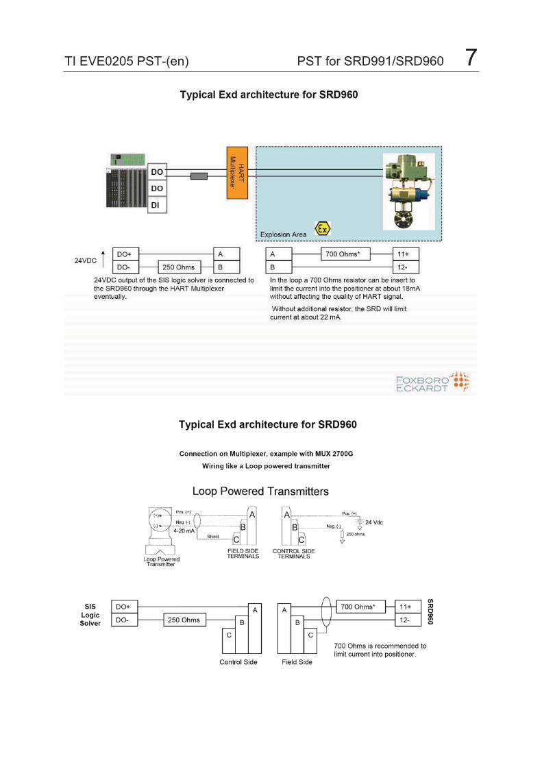
TI EVE0205 PST-(en) PST for SRD991/SRD960 7
8 PST for SRD991/SRD960 TI EVE0205 PST-(en)
3 PST in detail
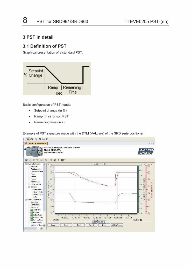
3.1 Definition of PST Graphical presentation of a standard PST:
Basic configuration of PST needs:
• Setpoint change (in %)
• Ramp (in s) for soft PST
• Remaining time (in s)
Example of PST signature made with the DTM (VALcare) of the SRD serie positioner.

TI EVE0205 PST-(en) PST for SRD991/SRD960 93.2 Three Alarms on PST:
Pressure Control Active At any time the positioner monitors the input and output pressure.
Air supply pressure monitoring:
If the input air supply pressure falls below a certain level, an alarm can be set to indicate that some maintenance should be done on the air supply line.
Air output monitoring:
On the output pressure, a minimum pressure is also set in order to abort the PST in case during test pressure fall below a certain value. Like this positioner avoids in case the valve stuck a possible overshoot.
Time limit Max. Wait Time for Position Change The Maximum Wait Time for Position Change is the time in Seconds how long the positioner will keep the Setpoint Change active. If the valve is not stuck, the positioner will perform the setpoint change and return back to the fully open 100% position immediately. In the case the valve should have a sluggish reaction, be sticky or stuck then the positioner will continue to apply the Setpoint Change as long as the configured Maximum Wait Time for Position Change. If after that time the valve doesn’t move, the positioner will discontinue the test and set the Testing Status: Error.
Maximum time to re-inflate
An alarm on the maximum time to re-inflate (re-open in case of ESD or re-closed in case of ESV) need to be configured. The control at any PST of the re-inflating time highlight, increase of the friction of the valve as well as drift in the quality on air supply.

10 PST for SRD991/SRD960 TI EVE0205 PST-(en)
3.3 In – Output between SRD positioner and Logic Solver for positioner SRD960-BxExxxxxxxxx-BE or for positioner SRD991-BxExxxxxxx-BE
The test can be requested by the SIS Logic Solver itself and the information on the status of the test can be read also by the Logic Solver. Such types of architecture developed in collaboration with Triconex eliminates any human decision or intervention; and like this, as described by the IEC61508 and IEC61511, allows the system to reach the highest level of safety.
This architecture doesn’t use HART or any of the particular Invensys protocols which are not certified for safety applications but uses simple binaries input and output. It is important to notice that no additional electronic equipment (like HART splitter) is necessary. Only a direct connection through binaries input-output of the positioner with the Logic Solver is necessary. This solution is available regardless of the communication protocol!
The communication protocol is used only to send information to a PC or a DCS in charge of the diagnostic and predictive maintenance.
Of course SRD960/SRD991 for PST are compatible not only with Triconex but also with all other manufacturers of SIS Logic Solver.
Developped with

TI EVE0205 PST-(en) PST for SRD991/SRD960 11Default configuration of the in – output signal (output type 2)
Input 1 : „do PST“ When input signal goes from 1 to 0 positioner start PST
Output 2 : status PST Output at 1 – OK PST start output goes at 0 When PST successful output goes again to 1
When PST error, output remain at 0
Or Output 2 : status PST Type 2 (to be selected by software – see page 29) Output at 1 – OK PST start output flash (0 / 1 alternatively) When PST successful output goes again to 1
When PST error, output go to 0
12 PST for SRD991/SRD960 TI EVE0205 PST-(en)
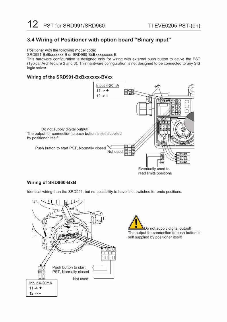
3.4 Wiring of Positioner with option board “Binary input”
Positioner with the following model code: SRD991-BxBxxxxxxx-B or SRD960-BxBxxxxxxxxx-B This hardware configuration is designed only for wiring with external push button to active the PST (Typical Architecture 2 and 3). This hardware configuration is not designed to be connected to any SIS logic solver.
Wiring of the SRD991-BxBxxxxxx-BVxx
Do not supply digital output! The output for connection to push button is self supplied by positioner itself!
Wiring of SRD960-BxB
Identical wiring than the SRD991, but no possibility to have limit switches for ends positions.
Input 4-20mA11 -> +12 -> -
Push button to start PST, Normally closed Not used
Eventually used to read limits positions
Push button to start PST, Normally closed
Not used Input 4-20mA11 -> +12 -> -
Do not supply digital output! The output for connection to push button is self supplied by positioner itself!

TI EVE0205 PST-(en) PST for SRD991/SRD960 133.5 Wiring of Positioner with option board “Binary in-output”
Positioner with the following model code: SRD9991-BxExxxxxxx-BE SRD960-BxExxxxxxxxx-BE This hardware configuration is designed for any architecture. This hardware configuration can be connected to any SIS logic solver.
Wiring of the SRD991-BxE
Take care of the polarity when supply with 24VDC! Positioner is protected for reverse polarity only for low power. In case of reverse polarity in 24VDC with high power output, positioner will be definitively damaged !
Assignation of Digital Input to 81+/82- and Digital Output to 83+/84- can be exchanged by configuration (DTM or EDD).
NAMUR Signals: Digital Input can be also read a NAMUR signal. Digital Output can generate a NAMUR signal in output. The selection of mode of work 24VDC or NAMUR can be executed by configuration (DTM or EDD).
Input 4-20mA or Input 24VDC11 -> + 11 -> +12 -> - 12 -> -
Digital Input Digital Output„do PST“ „Status PST“81 -> + 83 -> +82 -> - 84 -> -In and Output supplied by SIS logic solver or external source. Eventually used to
read limits positions

14 PST for SRD991/SRD960 TI EVE0205 PST-(en)
Wiring of SRD960-BxE
Identical wiring than the SRD991, without the possibility to have limit switches for ends positions.
Assignation of Digital Input to 81+/82- and Digital Output to 83+/84- can be exchanged by configuration (DTM or EDD).
NAMUR Signals: Digital Input can be also read a NAMUR signal. Digital Output can generate a NAMUR signal in output. The selection of mode of work 24VDC or NAMUR can be executed by configuration (DTM or EDD).
3.6 Wiring of LCP960 in combination with SRD960
LCP960 can be used in combination of any SRD960-xxE (option Board “Binary in-output”) Therefore LCP960 can be used with SRD960 HART or FF H1 or Profibus PA or FoxCom.
LCP960 must be in combination of SRD960 with Firmware 17.. In fact LCP960 needs to exploit the feedback signal PST status Type 2 (with flashing output status for PST running).
LCP960 can be installed directly in the near of the Safety Valve. LCP060 is ATEX Exd certified for application in hazardous area.
Input 4-20mA or Input 24VDC11 -> + 11 -> +12 -> - 12 -> -
Digital Input Digital Output„do PST“ „Status PST“81 -> + 83 -> +82 -> - 84 -> -In and Output supplied by SIS logic solver or external source.
Take care of the polarity when supply with 24VDC! Positioner is protected for reverse polarity only for low power. In case of reverse polarity in 24VDC with high power output, positioner will be definitively damaged !
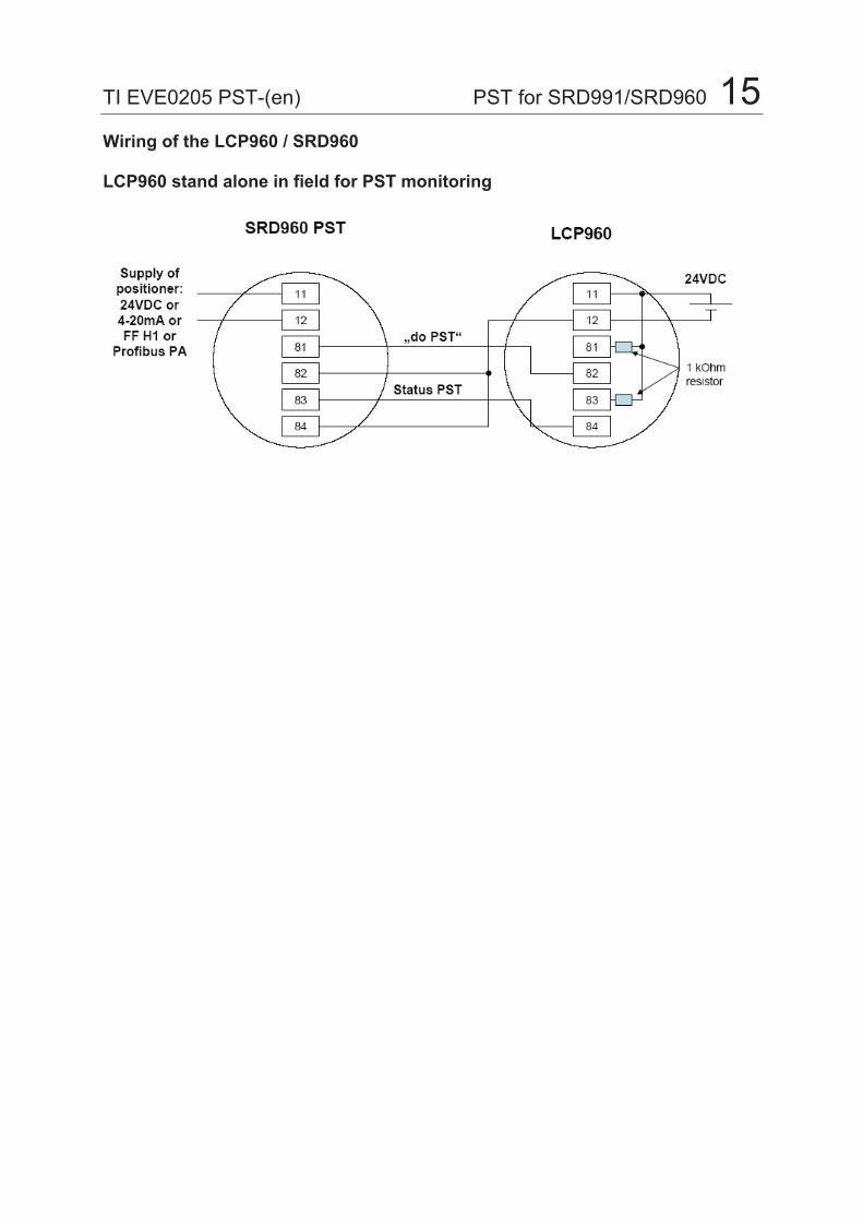
TI EVE0205 PST-(en) PST for SRD991/SRD960 15Wiring of the LCP960 / SRD960
LCP960 stand alone in field for PST monitoring

16 PST for SRD991/SRD960 TI EVE0205 PST-(en)
4 Start up and commissioning Follow the instruction of the Quick Guide for SRD991 or SRD960 (pneumatic connection and start up) After the Autostart has finished, connect the device with a FDT-DTM software (for example PACTware as FDTframe and VALcare or Valve Monitor as DTM for SRD devices). Devices SRD991-BxExxxxxxx-BE and SRD960-BxExxxxxxxxx-BE after autostart go to 100% and do not control the position in function of 4-20mA in input. This is normal because this devices are pre-configured for PST Start the communication with the SRD, read the configuration from the device and do the following changes:
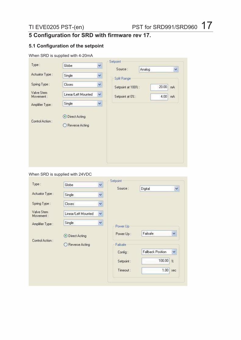
TI EVE0205 PST-(en) PST for SRD991/SRD960 175 Configuration for SRD with firmware rev 17.
5.1 Configuration of the setpoint
When SRD is supplied with 4-20mA
When SRD is supplied with 24VDC

18 PST for SRD991/SRD960 TI EVE0205 PST-(en)
5.2 Configuration of Cutoff:
If the valve is an Emergency Shut Down (valve closed with spring) Set a cutoff 100% at a value of 99% for example. Like this even if the 20mA supplied to the SRD is not precise, the valve will remain fully open.
If the valve is an Emergency Shut Vent (valve open with spring) Set a cutoff 0% at a value of 50% for example. Like this even if the 4mA supplied to the SRD is not precise, the valve will remain fully closed.

TI EVE0205 PST-(en) PST for SRD991/SRD960 195.3 Configuration of the input command of the PST For positioners SRD991-BxB or SRD960-BxB
Standard configuration is input 1 dedicate to command “do PST” Input 2 not used

20 PST for SRD991/SRD960 TI EVE0205 PST-(en)
5.4 Configuration of the in-output command of the PST For positioners SRD991-BxExxxxxxx-BE or SRD960-BxExxxxxxxxx-BE
First Binary InOut: Input Command from SIS logic solver “Do PST”
Attention : The configuration signal level has to correspond at the type of signal coming from the Logic Solver. For example for a Triconex Logic Solver, the type of signal (0/40mA) has to be selected.
Second Binary InOut: Output information to the SIS logic solver “status PST”
Select the correct signal level requested: - NAMUR when supplied 8VDC and NAMUR signal generated by SIS logic solver. - Binary when supplied 24VDC (positioner limit current to 40mA)
Select the correct signal level requested: - NAMUR when supplied 8VDC and NAMUR signal read by SIS logic solver. - Binary when supplied 24VDC (positioner limit current to 40mA)
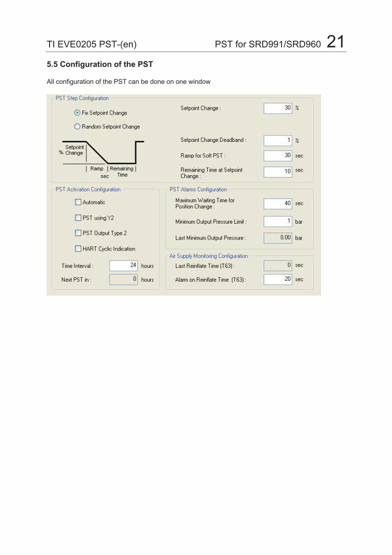
TI EVE0205 PST-(en) PST for SRD991/SRD960 215.5 Configuration of the PST
All configuration of the PST can be done on one window

22 PST for SRD991/SRD960 TI EVE0205 PST-(en)
5.5.1 PST Step Configuration With this window you can define the characteristic of the PST Step.
Fix Setpoint Change SRD will do the same Step at each test – same Setpoint Change
Random Setpoint Change SRD will perform a PST for a Random Setpoint Change between Setpoint Change (maximum value) and Minimum (Value) Setpoint Change
Setpoint Change Deadband is the deadband in % around the setpoint change to check when valve reach the requested Setpoint Change. As soon as Valve arrive inside the deadband, the timer of PST is stopped.
Ramp for Soft PST. Ramp in second to reach the setpoint change
Remaining Time at setpoint Time in second how long the valve will remain in stable position at the setpoint change. After that the valve will re-open at full speed.
100%
100% - Setpoint Change
Time in second
In case of an Emergency Shut Vent Valve, verify with the manufacturer of the valve, how much the valve can be opened without loosing the tightness. Usually a Setpoint Change of some few percents only is allowed.

TI EVE0205 PST-(en) PST for SRD991/SRD960 235.5.2 PST Activation
Automatic to select when the Positioner is executing alone at a certain Time Interval the PST. When not select the PST need an external command to be executed.
Next PST in Only for information. When PST is configure in Automatic, the countdown of the next PST is here visualized.
Time Interval Eventually the Time Interval can be set if the PST should be done automatically (without request). If the PST should be down on request this Time Interval is not used.The Time Interval has to be set to the value, after what time the Partial Stroke Test shall be repeated, when the Test is set to Automatic. The table shows some rough time-intervals. E.g.: The Time Interval is configured with 4380 hours. In this case every 4380 hours a Partial Stroke Test isexecuted. The interval can be configured between 0.1 to x hours and a maximum value equivalent of 13.6 years.
To select only if you want to perform a PST on a single acting actuator using a double acting positioner through the output Y2.
To select only if you want to have the status of PST in the HART Cyclic feedback information.
To select if you want the status Output Type 2 (flashing when PST is running)

24 PST for SRD991/SRD960 TI EVE0205 PST-(en)
5.5.3 PST Step Configuration
Max. Wait Time for Position Change The Maximum Wait Time for Position Change is the time in Seconds how long the positioner will keep the Setpoint Change active. If the valve is not stuck, the positioner will perform the setpoint change and return back to the fully open 100% position immediately. In the case the valve should have a sluggish reaction, be sticky or stuck then the positioner will continue to apply the Setpoint Change as long as the configured Maximum Wait Time for Position Change. If after that time the valve doesn’t move, the positioner will discontinue the test and set the PST Status: Error.Be careful to configure the Maximum Wait Time for Position Change greater than the Ramp given!
Minimum Output Pressure Limit The configuration of the Minimum Output Pressure Limit is very important in order to avoid overshooting in case the valve start to jam. Do one PST in charge and observe which Last Minimum Output Pressure reached the positioner to do the movement. Configure the PST pressure limit a little bit under this value.
Last Minimum Output Pressure Last Minimum Output Pressure is only an information that should help to the configuration of the Minimum Output Pressure Limit
MinimumOutputPressure during PST

TI EVE0205 PST-(en) PST for SRD991/SRD960 255.5.3 PST Air Supply Monitoring
Alarm on Reinflate Time is an alarm of time to see in how many second the valve go back to its 100%. Perform a PST and read the Last Reinflate Time. Put a little of time above the value read.
Last Reinflate Time is the measured time (T 63 – i.e. at 63% of jump) in second to re-open fully the valve (at 100%).
Time to re-open the valve at full speed

26 PST for SRD991/SRD960 TI EVE0205 PST-(en)
4.6 Special Configuration for use in combination with LCP960
These particulars points should be configured for a work of the SRD960 in combination of the LCP960.
TI EVE0205 PST-(en) PST for SRD991/SRD960 27
Additional Documentation for these products: Technical Information for Attachment Kits for Positioners TI EVE0011 A Overview of Attachment Kits of all positioners on actuators/valves of different
manufacturers
SRD991 / SRD960 Quick Guide: QG EVE0105 A/B SRD991 Extract of Master Instruction for an easy to use, understand, and fast
start-up guide. This document highlights the most important benefits. QG EVE0109 A SRD960 Extract of Master Instruction for an easy to use, understand, and fast
start-up guide. This document highlights the most important benefits.
Product Specification Sheet: PSS EVE0105 E SRD991 -all versions- PSS EVE0109 A SRD960 -all versions-
Master Instructions: MI EVE0105 E SRD991 -all versions- MI EVE0109 A SRD960 -HART and -FoxCom MI EVE0109 D SRD960 -PROFIBUS-PA and -FOUNDATION Fieldbus H1
Technical Information for Fieldbus-Communication: TI EVE0105 P SRD991/960 -PROFIBUS-PA TI EVE0105 Q SRD991/960 -FOUNDATION Fieldbus H1 Instruction for HART-Communication: MI EVE0105 B HART with Hand-Held Terminal
VEREENIGINGTel: 011 397 2833
Fax: 011 397 4700
DURBANTel: 031 579 2593
Fax: 031 579 2562
E-mail: [email protected]
Exports: [email protected]