SPUR GEAR PRODUT INE: Section 1453 CAST & DUCTILE …vp.salesmrc.com/pdfs/Sec_1453.pdf · SG-80510...
14
OPERATING RANGE SERIES DESCRIPTION Where shaft seal leakage is not allowable, for liquids that are hard to seal, or where seal maintenance is difficult, Viking Mag Drive® sealless SG pumps are the solution. In this type of pump, a canister hermetically seals the liquid within the pump. Inner magnets are connected to the pump drive shaft inside the canister, and an outer magnet assembly rotates outside of the canister, driven by a motor or other drive, so that magnetic forces pass through the canister to the inner magnets and cause the drive shaft to rotate. This eliminates traditional dynamic shaft seals, and problems associated with them (wear, leakage, air infiltration). A hollow drive shaft allows some liquid to flow by means of pressure differential from the high pressure side of the pump through the shaft, into the canister and back to the low pressure side of the pump. This provides magnet cooling and prevents product stagnation. SERIES NOMINAL FLOW MAXIMUM PRESSURE* TEMPERATURE RANGE VISCOSITY RANGE GPM m 3 /h PSI Bar °F °C SSU cSt SG-805 & SGN-805 0.7 - 11.2 .16 - 2.54 500 34 −40 to +450 −40 to +230 28 to 250,000 1 to 55,000 SG-807 & SGN-807 4 - 32 .91 - 7.27 500 34 −40 to +450 −40 to +230 28 to 250,000 1 to 55,000 SG-810 25 - 50 5.68 - 11.36 500 34 −40 to +450 −40 to +230 28 to 250,000 1 to 55,000 SG-814 70 - 190 15.9 - 43.15 500 34 −40 to +450 −40 to +230 28 to 250,000 1 to 55,000 * to 500 PSI (34 Bar) Continuous, to 2,500 PSI (170 Bar) Intermittent Pressure RELATED PRODUCTS Cast Iron Pumps: Catalog Section 1451 TABLE OF CONTENTS Features & Benefits ................................................................... 2 Model Number Key .................................................................... 2 Standard Materials of Construction ........................................... 2 Typical Applications.................................................................... 2 Specifications ............................................................................. 3 Mounting Options ....................................................................... 4 Dimensions – SG-805 & SGN-805 Series – MD-A (B Drive – Footed Bracket) .................................................................... 5 Dimensions – SG-807 & SGN-807 Series – MD-A (B Drive – Footed Bracket) .................................................................... 6 Dimensions – SG-807 & SGN-807 Series – MD-B (B Drive – Footed Bracket) .................................................................... 7 Dimensions – SG-810 Series MD2-B & SG-814 Series MD2-C (B Drive – Footed Bracket)........................................................ 8 Dimensions – "U" Models .......................................................... 8 Dimensions – "M" Models .......................................................... 8 Dimensions – SG-805 & SGN-805 Series – MD-A NEMA C (M Drive – Footless Bracket) .................................................................. 9 Dimensions – SG-807 & SGN-807 Series – MD-A NEMA C (M Drive – Footless Bracket) ................................................................ 10 Dimensions – SG-807 & SGN-807 Series – MD-A NEMA C (M Drive – Footed Bracket) .................................................................. 11 Dimensions – SG-807 & SGN-807 Series – MD-B NEMA C (M Drive – Footed Bracket) .................................................................. 12 Dimensions – SG-810 Series MD2-B & SG-814 Series MD2-C (M Drive – Footed Bracket) ..................................................... 13 Dimensions – "U" Models for NEMA C Face Motors............... 13 Dimensions – "M" Models for IEC B5 Flange Motors.............. 13 NPSH Required ....................................................................... 14 • A Unit of IDEX Corporation • Cedar Falls, IA ©2018 Section 1453 Page 1453.1 Issue D SERIES SG-805, SGN-805, SG-807, SGN-807, SG-810, SG-814 SPUR GEAR PRODUCT LINE: CAST & DUCTILE IRON SEALLESS MAG DRIVE PUMPS
Transcript of SPUR GEAR PRODUT INE: Section 1453 CAST & DUCTILE …vp.salesmrc.com/pdfs/Sec_1453.pdf · SG-80510...

OPERATING RANGE
SERIES DESCRIPTIONWhere shaft seal leakage is not allowable, for liquids that are hard to seal, or where seal maintenance is difficult, Viking Mag Drive® sealless SG pumps are the solution. In this type of pump, a canister hermetically seals the liquid within the pump. Inner magnets are connected to the pump drive shaft inside the canister, and an outer magnet assembly rotates outside of the canister, driven by a motor or other drive, so that magnetic forces pass through the canister to the inner magnets and cause the drive shaft to rotate. This eliminates traditional dynamic shaft seals, and problems associated with them (wear, leakage, air infiltration).
A hollow drive shaft allows some liquid to flow by means of pressure differential from the high pressure side of the pump through the shaft, into the canister and back to the low pressure side of the pump. This provides magnet cooling and prevents product stagnation.
SERIESNOMINAL FLOW MAXIMUM PRESSURE* TEMPERATURE RANGE VISCOSITY RANGE
GPM m3/h PSI Bar °F °C SSU cStSG-805 & SGN-805 0.7 - 11.2 .16 - 2.54 500 34 −40 to +450 −40 to +230 28 to 250,000 1 to 55,000
SG-807 & SGN-807 4 - 32 .91 - 7.27 500 34 −40 to +450 −40 to +230 28 to 250,000 1 to 55,000
SG-810 25 - 50 5.68 - 11.36 500 34 −40 to +450 −40 to +230 28 to 250,000 1 to 55,000
SG-814 70 - 190 15.9 - 43.15 500 34 −40 to +450 −40 to +230 28 to 250,000 1 to 55,000
* to 500 PSI (34 Bar) Continuous, to 2,500 PSI (170 Bar) Intermittent Pressure
RELATED PRODUCTSCast Iron Pumps: Catalog Section 1451
TABLE OF CONTENTSFeatures & Benefits ...................................................................2Model Number Key ....................................................................2Standard Materials of Construction ...........................................2Typical Applications ....................................................................2Specifications .............................................................................3Mounting Options .......................................................................4Dimensions – SG-805 & SGN-805 Series – MD-A (B Drive – Footed Bracket) ....................................................................5Dimensions – SG-807 & SGN-807 Series – MD-A (B Drive – Footed Bracket) ....................................................................6Dimensions – SG-807 & SGN-807 Series – MD-B (B Drive – Footed Bracket) ....................................................................7Dimensions – SG-810 Series MD2-B & SG-814 Series MD2-C (B Drive – Footed Bracket) ........................................................8Dimensions – "U" Models ..........................................................8Dimensions – "M" Models ..........................................................8Dimensions – SG-805 & SGN-805 Series – MD-A NEMA C (M Drive – Footless Bracket) ..................................................................9Dimensions – SG-807 & SGN-807 Series – MD-A NEMA C (M Drive – Footless Bracket) ................................................................10Dimensions – SG-807 & SGN-807 Series – MD-A NEMA C (M Drive – Footed Bracket) ..................................................................11Dimensions – SG-807 & SGN-807 Series – MD-B NEMA C (M Drive – Footed Bracket) ..................................................................12Dimensions – SG-810 Series MD2-B & SG-814 Series MD2-C (M Drive – Footed Bracket) .....................................................13Dimensions – "U" Models for NEMA C Face Motors ...............13Dimensions – "M" Models for IEC B5 Flange Motors ..............13NPSH Required .......................................................................14
• A Unit of IDEX Corporation • Cedar Falls, IA ©2018
Section 1453Page 1453.1Issue DSERIES SG-805, SGN-805, SG-807, SGN-807, SG-810, SG-814
SPUR GEAR PRODUCT LINE: CAST & DUCTILE IRON SEALLESS MAG DRIVE PUMPS

FEATURES & BENEFITS• Needle bearings provide high pressure capabilities,
sleeve bearing options available
• Close-coupled motor mount or foot bracket options to match space or motor requirements
STANDARD MATERIALS OF CONSTRUCTION
Component SG-805, -807 SGN-805, -807 SG-810, -814 OptionsCasing, Bracket, Head, Separation Plate Cast Iron, ASTM A823 Ductile Iron, ASTM A536 ③ Cast Iron, ASTM A48 Surface Hardening (Vitek)
Relief Valve Body Cast Iron, ASTM A823 Ductile Iron, ASTM A536 Cast Iron, ASTM A48 —
Relief Valve Poppet Hardened Steel Hardened Steel Ductile Iron, ASTM A536 —
Relief Valve Spring Steel, ASTM A229 Steel, ASTM A229 Chrome Silicon Spring Steel, ASTM A401 —
Gears Hardened Steel Hardened Steel Hardened Steel —
Shafts Case-Hardened Steel ASTM A322
Case-Hardened Steel ASTM A322
Case-Hardened Steel ASTM A322 Nitralloy
Anti-Friction Needle Bearings — — — Bearing Steel
Sleeve Bearings Carbon Graphite Carbon Graphite Carbon Graphite Silicon Carbide
O-Rings Buna-N Buna-N Buna-N Neoprene, PTFE, Kalrez®, Fluoroelastomer (FKM)
Canister 316L Stainless Steel 316L Stainless Steel 316L Stainless Steel Alloy C
Magnetic Coupling Bracket (not wetted) ④ Cast Iron, ASTM A823 ④ Cast Iron, ASTM A823 Cast Iron, ASTM A823 —
Magnets (outer magnets nickel plated, inner magnets sealed in SS canister) ① Neodymium Iron Boron ① Neodymium Iron Boron ① Neodymium Iron Boron ② Samarium Cobalt
① Maximum temperature 225°F / 107°C.② Maximum temperature 500°F / 260°C.③ Casing is Ductile Iron ASTM A536 Grade 65-45-12 (Vitek Hardened).④ Magnetic coupling brackets are aluminum for 182/184TC frame motors.
Kalrez is a registered trademark of E.I. du Pont de Nemours and company.
MODEL NUMBER KEY
TYPICAL APPLICATIONS• Fuels and Additives
• Polyurethane Meter / Mix
• Adhesive & Sealant Dispensing
• Pipeline Sampling
• Chemical Metering
• Heat Transfer Oils
NOTE: Direction of rotation: clockwise is standard, counter-clockwise is optional. Bi-rotational is not available as Mag Drive.
NOTE: Mag Drive pumps are connected to a magnetic coupling, which is specified separately. Coupling options are MD-A and MD-B (SG-805,-807), MD2-B (SG-810) or MD2-C (SG-814). Specify NEMA or IEC face mount for close-coupled or bearing carrier for long-coupled.
S G N - 8 0 5 1 8 - M 0 V
Shaft Rotation: (Viewed from Shaft End)0 = Clockwise (standard)1 = Counter-Clockwise (optional)
Seal Type:8 = Sealless
Mag Drive
Spur Gear Principle
Material of Construction:Blank = Cast IronN = Ductile Iron
(-805,-807)
Design Series:M = Standard
Relief Valve:V = With ValveO = Without Valve
Frame Size Pump Size
• A Unit of IDEX Corporation • Cedar Falls, IA ©2018
Section 1453Page 1453.2Issue D SERIES SG-805, SGN-805, SG-807, SGN-807, SG-810, SG-814
SPUR GEAR PRODUCT LINE: CAST & DUCTILE IRON SEALLESS MAG DRIVE PUMPS

⑤ Model
Number
Port Size
Nominal Capacity at 50 Hz Motor
Speeds(1450 RPM)
Nominal Capacity at 60 Hz Motor
Speeds(1750 RPM)
Maximum Continuous
Pressure
Approximate Shipping
Weight (Pump with Valve, but Less Power)
② Magnetic Coupling ①
Maximum Working Pressure
Approximate Shipping Weight (Coupling Only, Ready to Accept but Less Power)
Series
Torque
Inches GPM m3/h GPM m3/h PSIG BAR Lbs. Kg.Ft-Lbs Nm PSIG BAR Lbs. Kg.
SG-80518 ½ ③ 0.57 0.13 0.7 0.16 500 34 6 2.7
MD-A 49
5.412.2 1000 69 31 14
SG-80525 ½ ③ 0.84 0.19 1 0.23 500 34 6 2.7SG-80535 ½ ③ 1.14 0.26 1.4 0.32 500 34 6 2.7SG-80550 ½ ③ 1.67 0.38 2 0.45 500 34 7 3.2SG-80570 ½ ③ 2.33 0.53 2.8 0.64 500 34 7 3.2SG-80510 ½ ③ 3.30 0.75 4 0.91 500 34 8 3.6SG-80514 ¾ ③ 4.62 1.05 5.6 1.27 500 34 9 4.1SG-80519 ¾ ③ 6.30 1.43 7.6 1.73 200 14 10 4.5SG-80528 ¾ ③ 9.29 2.11 11.2 2.54 100 7 11 5.0SG-80741 1 ③ 3.30 0.75 4 0.91 500 34 15 6.8
MD-A 49
5.412.2 1000 69 31 14
SG-80758 1 ③ 4.62 1.05 5.6 1.27 500 34 17 7.7SG-80782 1 ③ 6.65 1.51 8 1.82 500 34 18 8.2SG-80711 1 ③ 9.29 2.11 11.2 2.54 500 34 19 8.6SG-80716 1 ③ 13 3.01 16 3.63 500 34 20 9.1
MD-B 40 54.0 500 28 71 32SG-80722 1½ x 1¼ ③ 18 4.14 22 5.00 500 34 41 18.6SG-80732 1½ x 1¼ ③ 27 6.02 32 7.27 500 34 43 19.5SG-81013 1½ ④ 21 4.70 25 5.68 500 34 49 22.1
MD2-B 700 48145 66
SG-81026 2 ④ 41 9.41 50 11.36 500 34 54 24.5 145 66SG-81420 2 ④ 58 13.17 70 15.90 500 34 130 59.1
MD2-C 350 2431 14
SG-81436 3 ④ 104 23.52 125 28.39 290 20 158 71.5 31 14SG-81456 4 ④ 157 35.75 190 43.15 190 13 189 85.8 31 14
SPECIFICATIONS
NOTE: Maximum temperature (standard construction) 225°F, 107°C. Higher temperatures can be handled with Samarium Cobalt magnets and optional O-ring elastomers. See page 1453.14 for torque and temperature limits.
① Optional high pressure canisters available. Consult factory.② See page 1453.14 for “Selecting the correct Mag Drive coupling.”③ NPT standard. Consult factory for other port size or type options such as BSP, SAE O-Ring or other.④ SAE J518 Code 61 flange with metric threaded fastener holes standard.
Consult factory for other port sizes or type options such as NPT, BSP, SAE O-Ring or other.⑤ Frame sizes 05 and 07 are also available in ductile iron (SGN)
• A Unit of IDEX Corporation • Cedar Falls, IA ©2018
Section 1453Page 1453.3Issue DSERIES SG-805, SGN-805, SG-807, SGN-807, SG-810, SG-814
SPUR GEAR PRODUCT LINE: CAST & DUCTILE IRON SEALLESS MAG DRIVE PUMPS

MOUNTING OPTIONS
Motor Mounted Units (M Drive) Pump and motor mounted to a flange mounting bracket with magnetic coupling.
This mounting arrangement eliminates the need for on-site coupling alignment that is normally required with a base mounted unit.
Series SG-805 & -807 pumps may be close coupled to NEMA-C faced motors and SG-810 & -814 to both NEMA-C and IEC B5 flanged motors to provide an easily-assembled, compact pumping unit. This mounting arrangement eliminates the need for on-site coupling alignment that is normally required for a base-mounted unit
Series: SG-805, SGN-805, SG-807, SGN-807, SG-810, SG-814
Foot Bracket Mounted Pumps (B Drive) Pump is mounted to a foot bracket.
Series SG-8 pumps are available with a bearing carrier mounted to the magnetic coupling to provide an external drive shaft for long-coupling to a reducer, gear motor or other drive. The 3.5” shaft height on MD-A couplings matches the shaft height on Viking “A” series reducers, as well as NEMA 56, 143 and 145 T motors. The 6.25” shaft height on MD-B couplings matches shaft height on 254/256 T motors. The MD2-B coupling for SG-810 has 5.5” shaft height matching Viking “B” reducers.
Series: SG-805, SGN-805, SG-807, SGN-807, SG-810, SG-814
• A Unit of IDEX Corporation • Cedar Falls, IA ©2018
Section 1453Page 1453.4Issue D SERIES SG-805, SGN-805, SG-807, SGN-807, SG-810, SG-814
SPUR GEAR PRODUCT LINE: CAST & DUCTILE IRON SEALLESS MAG DRIVE PUMPS

These dimensions are average and not for construction purposes. Certified prints on request.
NOTE: Dimensions in inches (millimeters)
DIMENSIONS – SG-805 & SGN-805 SERIES – MD-A (B DRIVE – FOOTED BRACKET)
Model Number A(in)
WITH R/V LESS R/VDD
B C E B C E
SG-80518MD-A SGN-80518MD-A ½
in 2.02 13.71 2.08 2.21 12.71 2.27 0.31
mm 51 348 53 56 323 58 8
SG-80525MD-A SGN-80525MD-A ½
in 2.09 13.78 2.15 2.28 12.78 2.34 0.31
mm 53 350 55 58 325 59 8
SG-80535MD-A SGN-80535MD-A ½
in 2.19 13.88 2.25 2.38 12.88 2.44 0.31
mm 56 352 57 60 327 62 8
SG-80550MD-ASGN-80550MD-A ½
in 2.34 14.03 2.40 2.53 13.03 2.59 0.31
mm 59 356 61 64 331 66 8
SG-80570MD-A SGN-80570MD-A ½
in 2.54 14.23 2.60 2.73 13.23 2.79 0.31
mm 65 361 66 69 336 71 8
SG-80510MD-A SGN-80510MD-A ½
in 1.84 14.53 1.90 1.84 13.53 1.90 0.31
mm 47 369 48 47 344 48 8
SG-80514MD-A SGN-80514MD-A ¾
in 2.04 14.93 2.10 2.04 13.93 2.10 0.19
mm 52 379 53 52 354 53 5
SG-80519MD-A SGN-80519MD-A ¾
in 2.29 15.43 2.35 2.29 14.43 2.35 0.19
mm 58 392 60 58 367 60 5
SG-80528MD-A SGN-80528MD-A ¾
in 2.04 16.33 2.10 2.04 15.33 2.10 0.19
mm 52 415 53 52 389 53 5
• A Unit of IDEX Corporation • Cedar Falls, IA ©2018
Section 1453Page 1453.5Issue DSERIES SG-805, SGN-805, SG-807, SGN-807, SG-810, SG-814
SPUR GEAR PRODUCT LINE: CAST & DUCTILE IRON SEALLESS MAG DRIVE PUMPS

NOTE: Dimensions in inches (millimeters)
S = Suction PortD = Discharge Port
These dimensions are average and not for construction purposes. Certified prints on request.
DIMENSIONS – SG-807 & SGN-807 SERIES – MD-A (B DRIVE – FOOTED BRACKET)
Model Number A(in)
WITH R/V LESS R/VB C E B C E
SG-80741MD-A SGN-80741MD-A ½
in 3.07 15.81 3.13 3.26 14.19 3.32
mm 78 402 80 83 360 84
SG-80758MD-A SGN-80758MD-A ½
in 3.24 15.98 3.30 3.43 14.36 3.49
mm 82 406 84 87 365 89
SG-80782MD-A SGN-80782MD-A ½
in 3.48 16.22 3.54 3.67 14.60 3.73
mm 88 412 90 93 371 95
SG-80711MD-A SGN-80711MD-A ½
in 3.81 16.55 3.87 4.00 14.93 4.06
mm 97 420 98 102 379 103
SG-80716MD-A SGN-80716MD-A ¾
in 4.31 17.05 4.37 4.50 15.43 4.56
mm 109 433 111 114 392 116
SG-80722MD-A SGN-80722MD-A
1½ S1¼ D
in 4.25 20.20 4.31 4.25 18.58 4.31
mm 108 513 109 108 472 109
SG-80732MD-A SGN-80732MD-A
1½ S1¼ D
in 4.28 20.72 4.34 4.27 19.10 4.33
mm 109 526 110 108 485 110
• A Unit of IDEX Corporation • Cedar Falls, IA ©2018
Section 1453Page 1453.6Issue D SERIES SG-805, SGN-805, SG-807, SGN-807, SG-810, SG-814
SPUR GEAR PRODUCT LINE: CAST & DUCTILE IRON SEALLESS MAG DRIVE PUMPS

These dimensions are average and not for construction purposes. Certified prints on request.
NOTE: Dimensions in inches (millimeters)
S = Suction PortD = Discharge Port
DIMENSIONS – SG-807 & SGN-807 SERIES – MD-B (B DRIVE – FOOTED BRACKET)
Model Number A(in)
WITH R/V LESS R/VB C E B C E
SG-80741MD-B SGN-80741MD-B ½
in 3.07 20.07 3.13 3.26 18.45 3.32
mm 78 510 80 83 469 84
SG-80758MD-B SGN-80758MD-B ½
in 3.24 20.24 3.30 3.43 18.61 3.49
mm 82 514 84 87 473 89
SG-80782MD-B SGN-80782MD-B ½
in 3.48 20.48 3.54 3.67 18.86 3.73
mm 88 520 90 93 479 95
SG-80711MD-B SGN-80711MD-B ½
in 3.81 20.81 3.87 4.00 19.19 4.06
mm 97 529 98 102 487 103
SG-80716MD-B SGN-80716MD-B ¾
in 4.31 21.30 4.37 4.50 19.68 4.56
mm 109 541 111 114 500 116
SG-80722MD-B SGN-80722MD-B
1½ S1¼ D
in 4.25 24.46 4.31 4.25 22.83 4.31
mm 108 621 109 108 580 109
SG-80732MD-B SGN-80732MD-B
1½ S1¼ D
in 4.28 24.98 4.34 4.27 23.36 4.33
mm 109 634 110 108 593 110
• A Unit of IDEX Corporation • Cedar Falls, IA ©2018
Section 1453Page 1453.7Issue DSERIES SG-805, SGN-805, SG-807, SGN-807, SG-810, SG-814
SPUR GEAR PRODUCT LINE: CAST & DUCTILE IRON SEALLESS MAG DRIVE PUMPS

DIMENSIONS – SG-810 SERIES MD2-B & SG-814 SERIES MD2-C (B DRIVE – FOOTED BRACKET)
DIMENSIONS – "U" MODELS
DIMENSIONS – "M" MODELS
① Less Relief Valve ② With Relief Valve ③ MD2-B ④ MD2-C NOTE: Dimensions in inches (millimeters)
These dimensions are average and not for construction purposes. Certified prints on request.
Pump AB W① W② N R S A (in) X Y L③ L④ Z B
SG-81013in 5.91 2.13 2.07 1.90 0.70
M12 x 1.75 x 19.5 1.501.00 3.63 6.98 6.85 6.63 3.00
mm 150 54 53 48 18 25 92 177 174 168 76
SG-81026in 6.13 2.88 2.82 1.53 0.84
M12 x 1.75 x 19.5 2.001.00 3.63 7.20 7.07 6.63 3.00
mm 156 73 72 39 21 25 92 183 180 168 76
SG-81420in 6.10 2.43 2.37 0.84 1.53
M12 x 1.75 x 19.5 2.001.50 3.63 — 7.04 7.09 4.50
mm 155 62 60 21 39 38 92 — 179 180 114
SG-81436in 6.80 2.73 3.27 1.21 2.09
M16 x 2 x 28.5 3.001.50 3.63 — 7.74 7.09 4.50
mm 173 69 83 31 53 38 92 — 197 180 114
SG-81456in 7.19 4.94 4.88 1.53 2.56
M16 x 2 x 28.5 4.001.50 3.63 — 8.13 7.09 4.50
mm 183 126 124 39 65 38 92 — 207 180 114
Coupling D E F G H J K M O P T U V AC AD AEMD2-B
(SG-810) in 5.50 2.75 4.88 7.00 6.52 0.56 2.12 7.30 0.53 0.88 2.72 1.13 0.25 4.50 9.30 2.87
MD2-C (SG-810, SG-814) in 6.69 3.75 5.75 10.00 8.69 0.95 2.50 11.14 0.76 1.56 4.07 1.88 0.50 5.91 11.20 5.50
Coupling D E F G H J K M O P T U V AC AD AEMD2-B
(SG-810) mm 145 70 89 178 130 15 46 192 14 22 56 28 8 125 216 78
MD2-C (SG-814) mm 170 95 146 254 221 24 63 283 19 36 103 48 14 150 285 140
• A Unit of IDEX Corporation • Cedar Falls, IA ©2018
Section 1453Page 1453.8Issue D SERIES SG-805, SGN-805, SG-807, SGN-807, SG-810, SG-814
SPUR GEAR PRODUCT LINE: CAST & DUCTILE IRON SEALLESS MAG DRIVE PUMPS

These dimensions are average and not for construction purposes. Certified prints on request.
NOTE: Dimensions in inches (millimeters)NOTE: Footless bracket requires footed motor.
* Motor shaft must be modified to resemble 182TC-184TC shaft length, diameter and key.
DIMENSIONS – SG-805 & SGN-805 SERIES – MD-A NEMA C (M DRIVE – FOOTLESS BRACKET)
Model Number A(in)
WITH R/V LESS R/VDD
B C B C
SG-80518MD-A SGN-80518MD-A ½
in 2.02 9.15 2.21 8.15 0.31
mm 51 232 56 207 8
SG-80525MD-A SGN-80525MD-A ½
in 2.09 9.22 2.28 8.22 0.31
mm 53 234 58 209 8
SG-80535MD-A SGN-80535MD-A ½
in 2.19 9.32 2.38 8.32 0.31
mm 56 237 60 211 8
SG-80550MD-ASGN-80550MD-A ½
in 2.34 9.47 2.53 8.47 0.31
mm 59 241 64 215 8
SG-80570MD-A SGN-80570MD-A ½
in 2.54 9.67 2.73 8.67 0.31
mm 65 246 69 220 8
SG-80510MD-A SGN-80510MD-A ½
in 1.84 9.97 1.84 8.97 0.31
mm 47 253 47 228 8
SG-80514MD-A SGN-80514MD-A ¾
in 2.04 10.37 2.04 9.37 0.19
mm 52 263 52 238 5
SG-80519MD-A SGN-80519MD-A ¾
in 2.29 10.87 2.29 9.87 0.19
mm 58 276 58 251 5
SG-80528MD-A SGN-80528MD-A ¾
in 2.04 11.77 2.04 10.77 0.19
mm 52 299 52 274 5
Motor Frame Size D E F H J (in) MC
56C3.50 2.44 1.50 0.34
SLOT 5.252.56
89 62 38 9 65
143TC3.50 2.75 2.00 0.34
5.252.88
89 70 51 9 73
145TC3.50 2.75 2.50 0.34
5.252.88
89 70 64 9 73
182TC4.50 3.75 2.25 0.41
5.693.62
114 95 57 10 92
184TC4.50 3.75 2.75 0.41
5.693.62
114 95 70 10 92
213TC*5.25 4.25 2.75 0.41
5.694.50
133 108 70 10 114
• A Unit of IDEX Corporation • Cedar Falls, IA ©2018
Section 1453Page 1453.9Issue DSERIES SG-805, SGN-805, SG-807, SGN-807, SG-810, SG-814
SPUR GEAR PRODUCT LINE: CAST & DUCTILE IRON SEALLESS MAG DRIVE PUMPS

These dimensions are average and not for construction purposes. Certified prints on request.
NOTE: Dimensions in inches (millimeters)NOTE: Footless bracket requires footed motor.
* Motor shaft must be modified to resemble 182TC-184TC shaft length, diameter and key.
DIMENSIONS – SG-807 & SGN-807 SERIES – MD-A NEMA C (M DRIVE – FOOTLESS BRACKET)
Model Number A(in)
WITH R/V LESS R/VB C B C
SG-80741MD-A SGN-80741MD-A ½
in 3.07 11.25 3.26 9.63
mm 78 286 83 245
SG-80758MD-A SGN-80758MD-A ½
in 3.24 11.42 3.43 9.80
mm 82 290 87 249
SG-80782MD-A SGN-80782MD-A ½
in 3.48 11.66 3.67 10.04
mm 88 296 93 255
SG-80711MD-A SGN-80711MD-A ½
in 3.81 11.99 4.00 10.37
mm 97 305 102 263
SG-80716MD-A SGN-80716MD-A ½
in 4.31 12.49 4.50 10.87
mm 109 317 114 276
SG-80722MD-A SGN-80722MD-A ½
in 4.25 15.64 4.25 15.02
mm 108 397 108 356
SG-80732MD-A SGN-80732MD-A ¾
in 4.75 16.64 4.75 15.02
mm 121 423 121 382
Motor Frame Size D E F H J (in) MC
56C3.50 2.44 1.50 0.34
SLOT 5.252.56
89 62 38 9 65
143TC3.50 2.75 2.00 0.34
5.252.88
89 70 51 9 73
145TC3.50 2.75 2.50 0.34
5.252.88
89 70 64 9 73
182TC4.50 3.75 2.25 0.41
5.693.62
114 95 57 10 92
184TC4.50 3.75 2.75 0.41
5.693.62
114 85 70 10 92
213TC*5.25 4.25 2.75 0.41
5.694.50
133 108 70 10 114
• A Unit of IDEX Corporation • Cedar Falls, IA ©2018
Section 1453Page 1453.10Issue D SERIES SG-805, SGN-805, SG-807, SGN-807, SG-810, SG-814
SPUR GEAR PRODUCT LINE: CAST & DUCTILE IRON SEALLESS MAG DRIVE PUMPS

These dimensions are average and not for construction purposes. Certified prints on request.
DIMENSIONS – SG-807 & SGN-807 SERIES – MD-A NEMA C (M DRIVE – FOOTED BRACKET)
Model Number A(in)
WITH R/V LESS R/V Motor FrameB C E B C E
SG-80741MD-A SGN-80741MD-A 1
in 3.07 11.25 3.13 3.26 9.63 3.32
56C143TC145TC
mm 78 286 80 83 245 84
SG-80758MD-A SGN-80758MD-A 1
in 3.24 11.42 3.30 3.43 9.80 3.49
mm 82 290 84 87 249 89
SG-80782MD-A SGN-80782MD-A 1
in 3.48 11.66 3.54 3.67 10.04 3.73
mm 88 269 90 93 255 95
SG-80711MD-A SGN-80711MD-A 1
in 3.81 11.99 3.87 4.00 10.37 4.06
mm 97 305 98 102 263 103
SG-80716MD-A SGN-80716MD-A 1
in 4.31 12.49 4.37 4.50 10.87 4.56
mm 109 317 111 114 276 116
SG-80722MD-A SGN-80722MD-A
1½ S1¼ D
in 4.25 15.64 4.31 4.25 14.02 4.31
mm 108 397 109 108 356 109
SG-80732MD-A SGN-80732MD-A
1½ S1¼ D
in 4.75 16.64 4.81 4.75 15.02 4.81
mm 121 423 122 121 382 122
NOTE: Dimensions in inches (millimeters)NOTE: Footed bracket requires footless motor.
S = Suction PortD = Discharge PortFooted bracket is only available for up to NEMA 145TC frame motors (4.5” rabbet) - 180TC and 210TC motor frames with 8.5” rabbet are only available with footless bracket.
• A Unit of IDEX Corporation • Cedar Falls, IA ©2018
Section 1453Page 1453.11Issue DSERIES SG-805, SGN-805, SG-807, SGN-807, SG-810, SG-814
SPUR GEAR PRODUCT LINE: CAST & DUCTILE IRON SEALLESS MAG DRIVE PUMPS

DIMENSIONS – SG-807 & SGN-807 SERIES – MD-B NEMA C (M DRIVE – FOOTED BRACKET)
Model Number A(in)
WITH R/V LESS R/VDD
B C E B C E
SG-80741MD-B SGN-80741MD-B 1
in 2.60 13.97 3.79 2.80 12.35 3.98
182TC/184TC213TC/215TC
254TC/256TC ①
mm 66 355 96 71 314 101
SG-80758MD-B SGN-80758MD-B 1
in 2.77 14.14 3.96 2.97 12.52 4.15
mm 70 359 101 75 318 105
SG-80782MD-B SGN-80782MD-B 1
in 3.01 14.38 4.20 3.21 12.76 4.39
mm 76 365 107 82 324 112
SG-80711MD-B SGN-80711MD-B 1
in 3.34 14.17 4.53 3.54 13.09 4.72
mm 85 374 115 90 332 120
SG-80716MD-B SGN-80716MD-B 1
in 3.84 15.20 5.03 4.04 13.59 5.22
mm 98 386 128 103 345 133
SG-80722MD-B SGN-80722MD-B
1½ S1¼ D
in 3.78 18.35 4.97 3.78 16.73 4.97
mm 96 466 126 96 425 126
SG-80732MD-B SGN-80732MD-B
1½ S1¼ D
in 4.28 19.35 5.47 4.28 17.73 5.47
mm 109 491 139 109 450 139
NOTE: Dimensions in inches (millimeters)NOTE: Footed bracket requires footless motor.
S = Suction PortD = Discharge PortCoupling will accept NEMA motor frames 182TC-256TC.① NEMA 254TC-256TC will require shaft modification reducing shaft extension by ⅝”.
These dimensions are average and not for construction purposes. Certified prints on request.
• A Unit of IDEX Corporation • Cedar Falls, IA ©2018
Section 1453Page 1453.12Issue D SERIES SG-805, SGN-805, SG-807, SGN-807, SG-810, SG-814
SPUR GEAR PRODUCT LINE: CAST & DUCTILE IRON SEALLESS MAG DRIVE PUMPS
These dimensions are average and not for construction purposes. Certified prints on request.
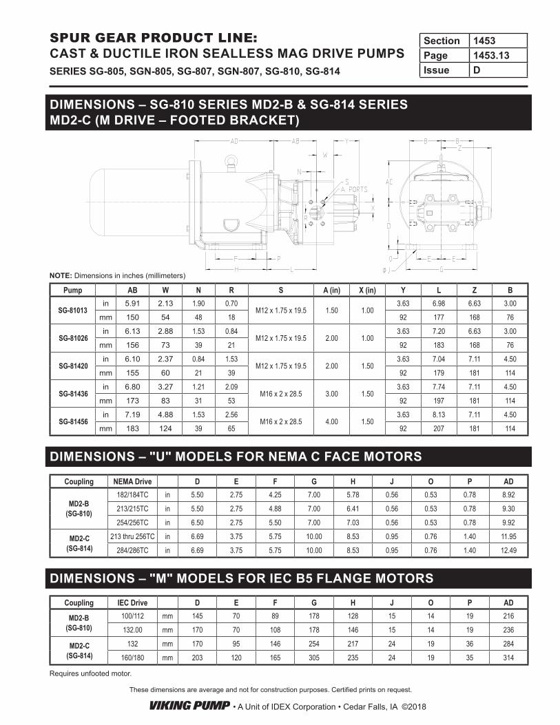
DIMENSIONS – SG-810 SERIES MD2-B & SG-814 SERIES MD2-C (M DRIVE – FOOTED BRACKET)
DIMENSIONS – "U" MODELS FOR NEMA C FACE MOTORS
DIMENSIONS – "M" MODELS FOR IEC B5 FLANGE MOTORS
Pump AB W N R S A (in) X (in) Y L Z B
SG-81013in 5.91 2.13 1.90 0.70
M12 x 1.75 x 19.5 1.50 1.003.63 6.98 6.63 3.00
mm 150 54 48 18 92 177 168 76
SG-81026in 6.13 2.88 1.53 0.84
M12 x 1.75 x 19.5 2.00 1.003.63 7.20 6.63 3.00
mm 156 73 39 21 92 183 168 76
SG-81420in 6.10 2.37 0.84 1.53
M12 x 1.75 x 19.5 2.00 1.503.63 7.04 7.11 4.50
mm 155 60 21 39 92 179 181 114
SG-81436in 6.80 3.27 1.21 2.09
M16 x 2 x 28.5 3.00 1.503.63 7.74 7.11 4.50
mm 173 83 31 53 92 197 181 114
SG-81456in 7.19 4.88 1.53 2.56
M16 x 2 x 28.5 4.00 1.503.63 8.13 7.11 4.50
mm 183 124 39 65 92 207 181 114
Coupling NEMA Drive D E F G H J O P AD
MD2-B (SG-810)
182/184TC in 5.50 2.75 4.25 7.00 5.78 0.56 0.53 0.78 8.92
213/215TC in 5.50 2.75 4.88 7.00 6.41 0.56 0.53 0.78 9.30
254/256TC in 6.50 2.75 5.50 7.00 7.03 0.56 0.53 0.78 9.92
MD2-C (SG-814)
213 thru 256TC in 6.69 3.75 5.75 10.00 8.53 0.95 0.76 1.40 11.95
284/286TC in 6.69 3.75 5.75 10.00 8.53 0.95 0.76 1.40 12.49
Coupling IEC Drive D E F G H J O P AD
MD2-B (SG-810)
100/112 mm 145 70 89 178 128 15 14 19 216
132.00 mm 170 70 108 178 146 15 14 19 236
MD2-C (SG-814)
132 mm 170 95 146 254 217 24 19 36 284
160/180 mm 203 120 165 305 235 24 19 35 314
NOTE: Dimensions in inches (millimeters)
Requires unfooted motor.
• A Unit of IDEX Corporation • Cedar Falls, IA ©2018
Section 1453Page 1453.13Issue DSERIES SG-805, SGN-805, SG-807, SGN-807, SG-810, SG-814
SPUR GEAR PRODUCT LINE: CAST & DUCTILE IRON SEALLESS MAG DRIVE PUMPS

SELECTING THE CORRECT VIKING MAG DRIVE® COUPLING
STANDARD NEODYMIUM MAGNETS(For Application Temperatures Below 225°F.)
ApplicationTemp. (°F) AMB 100 125 150 175 200 225
ApplicationTemp. (°C) 20 38 52 66 79 93 107
TCF 1.0 .94 .88 .82 .76 .70 .64
Table 1: Temperature Correction Factors
4. Divide calculated application torque by TCF to get adjusted application torque.
5. Select coupling with rating equal to or greater than “adjusted application torque” (AAT) from Table 3. Viking couplings have a built-in service factor, so if you have calculated the AAT correctly, you can be comfortable with a coupling that is equal to your calculated torque.
Table 3
OPTIONAL SAMARIUM COBALT MAGNETS(For Application Temperatures Above 225°F.)
ApplicationTemp. (°F) 175 200 300 400 500
ApplicationTemp. (°C) 79 93 749 204 260
TCF .74 .73 .69 .63 .59
Table 2: Temperature Correction Factors
1. Find pump HP and speed from the performance curves, which can be electronically generated with the Viking Pump Curve Generator, located on www.vikingpump.com.
2. Calculate the application torque (T), using this formula:
T (FT-LB) = X 5252
3. Select the temperature correction factor (TCF) from Table 1 or Table 2.
1. An application calls for pumping 1 GPM of 100 SSU (22 cSt) liquid at 400 PSI (27 Bar), at 100°F (38C), with a 1750 RPM motor. From the pump selector, an SG-80525 is selected, providing .95 GPM (3.6 LPM) at 1750 RPM, with .35 BHP (.26 kW).
2. Calculate torque (T).
TORQUE (T) = X 5252
= 1.05 FT-LB
3. From the temperature correction factor table, the correc tion factor (TCF) = .94.
4. Calculate adjusted application torque.
ADJUSTED APPLICATION TORQUE =
= 1.12 FT-LB
5. Select coupling.
THE NEODYMIUM MD-A4 (4 FT-LB RATING >1.12 FT-LB AAT) COUPLING IS THE PROPER SELECTION
EXAMPLE
.351750
1.05.94
HPSPEED
MAGNETIC COUPLING TORQUE RATING TABLECoupling Size Torque (FT-LBS) Nm
MD-A4 4 5.4MD-A9 9 12.2
MD-B40 40 54.2MD2-B14 14 19.0MD2-B32 32 43.4MD2-B50 50 67.8MD2-C40 40 54.2MD2-C90 90 122.0
MD2-C135 135 183.0MD2-C180 180 244.0
NPSH REQUIRED
Printed performance curves are not available.Performance curves can be electronically generated with the Viking Pump Curve Generator on vikingpump.com.NPSHR data is not available on the curve generator.
• A Unit of IDEX Corporation • Cedar Falls, IA ©2018
Section 1453Page 1453.14Issue D SERIES SG-805, SGN-805, SG-807, SGN-807, SG-810, SG-814
SPUR GEAR PRODUCT LINE: CAST & DUCTILE IRON SEALLESS MAG DRIVE PUMPS