SPS/RPS Installation Instructions...3 The System Power Supply (SPS) and Remote Power Supply (RPS)...
32
SPS/RPS Installation Instructions 2005, 2008, 2009, 2011 SimplexGrinnell LP. All rights reserved. Specifications and other information shown were current as of publication and are subject to change without notice. Simplex and the Simplex logo are trademarks of Tyco International Ltd. and its affiliates and are used under license. 579-246 Rev. K This publication describes the installation procedure for the following 4100-Series System Power Supplies (SPS) and Remote Power Supplies (RPS): 4100-5111/5112 SPS (120 VAC) (mounts to expansion bays only) 4100-5125/5126 RPS (120 VAC) 4100-5113 SPS (220/230/240 VAC) (mounts to expansion bays only) 4100-5127 RPS (220/230/240 VAC) These products are compatible with 4100U and 4100ES Fire Alarm Control Panels (FACP). IMPORTANT: The SPS described in this document are not physically the same as the SPS used in the CPU bay. Verify FACP System Programmer, Executive, and Slave Software compatibility when installing, or replacing system components. Refer to the Technical Support Information and Downloads website for compatibility information. This publication discusses the following topics: Topic See Page # Cautions and Warnings 2 Introduction to the SPS and RPS 3 Mounting 7 Configuring the SPS and RPS 8 Internal Wiring 10 NAC Field Wiring 12 IDNet Field Wiring (SPS only) 23 Auxiliary Power Wiring 26 Auxiliary Relay Wiring 29 Troubleshooting 31 City and relay connections can be made from the SPS (the RPS supports relay connections only). Refer to the City and Relay Card Installation Instructions (574-839) to install a relay card to the SPS, or a city card to the SPS or RPS. To find out more about the CPU bay version of the SPS, which operates in the same way as the expansion bay version of the SPS but mounts differently, refer to the 4100ES Fire Alarm System Installation Guide (574-848). For information on Expansion Power Supplies (XPS), refer to XPS and XNAC Installation Instructions (574-772). Introduction In this Publication Related Documentation
Transcript of SPS/RPS Installation Instructions...3 The System Power Supply (SPS) and Remote Power Supply (RPS)...

SPS/RPS Installation Instructions
2005, 2008, 2009, 2011 SimplexGrinnell LP. All rights reserved. Specifications and other information shown were current as of publication and are subject to change without notice. Simplex and the Simplex logo are trademarks of Tyco International Ltd. and its affiliates and are used under license.
579-246 Rev. K
This publication describes the installation procedure for the following 4100-Series System Power Supplies (SPS) and Remote Power Supplies (RPS): 4100-5111/5112 SPS (120 VAC) (mounts to expansion bays only) 4100-5125/5126 RPS (120 VAC) 4100-5113 SPS (220/230/240 VAC) (mounts to expansion bays only) 4100-5127 RPS (220/230/240 VAC) These products are compatible with 4100U and 4100ES Fire Alarm Control Panels (FACP). IMPORTANT:
The SPS described in this document are not physically the same as the SPS used in the CPU bay.
Verify FACP System Programmer, Executive, and Slave Software compatibility when installing, or replacing system components. Refer to the Technical Support Information and Downloads website for compatibility information.
This publication discusses the following topics:
Topic See Page #
Cautions and Warnings 2
Introduction to the SPS and RPS 3
Mounting 7
Configuring the SPS and RPS 8
Internal Wiring 10
NAC Field Wiring 12
IDNet Field Wiring (SPS only) 23
Auxiliary Power Wiring 26
Auxiliary Relay Wiring 29
Troubleshooting 31
City and relay connections can be made from the SPS (the RPS supports relay connections only). Refer to the City and Relay Card Installation Instructions (574-839) to install a relay card to the SPS, or a city card to the SPS or RPS. To find out more about the CPU bay version of the SPS, which operates in the same way as the expansion bay version of the SPS but mounts differently, refer to the 4100ES Fire Alarm System Installation Guide (574-848). For information on Expansion Power Supplies (XPS), refer to XPS and XNAC Installation Instructions (574-772).
Introduction
In this Publication
Related Documentation

2
READ AND SAVE THESE INSTRUCTIONS- Follow the instructions in this installation manual. These instructions must be followed to avoid damage to this product and associated equipment. Product operation and reliability depend upon proper installation.
DO NOT INSTALL ANY SIMPLEX® PRODUCT THAT APPEARS DAMAGED- Upon
unpacking your Simplex product, inspect the contents of the carton for shipping damage. If
damage is apparent, immediately file a claim with the carrier and notify an authorized Simplex product supplier. ELECTRICAL HAZARD - Disconnect electrical field power when making any internal adjust-ments or repairs. All repairs should be performed by a representative or authorized agent of your local Simplex product supplier.
STATIC HAZARD - Static electricity can damage components. Handle as follows:
Ground yourself before opening or installing. Prior to installation, keep components wrapped in anti-static material at all times. FCC RULES AND REGULATIONS – PART 15 - This equipment has been tested and found to comply with the limits for a Class A digital device pursuant to Part 15 of the FCC Rules. These limits are designed to provide reasonable protection against harmful interference when the equipment is operated in a commercial environment. This equipment generates, uses, and can radiate radio frequency energy and, if not installed and used in accordance with the instruction manual, may cause harmful interference to radio communications. Operation of this equipment in a residential area is likely to cause harmful interference in which case the user will be required to correct the interference at his own expense. SYSTEM REACCEPTANCE TEST AFTER SOFTWARE CHANGES - To ensure proper system operation, this product must be tested in accordance with NFPA72 after any programming operation or change in site-specific software. Reacceptance testing is required after any change, addition or deletion of system components, or after any modification, repair or adjustment to system hardware or wiring. All components, circuits, system operations, or software functions, known to be affected by a change, must be 100% tested. In addition, to ensure that other operations are not inadvertently affected, at least 10% of initiating devices that are not directly affected by the change, up to a maximum of 50 devices, must also be tested and proper system operation verified.
Cautions and Warnings

3
The System Power Supply (SPS) and Remote Power Supply (RPS) are both intended to be placed in remote cabinets that require a 24 VDC signal power, as well as battery charging capabilities. The SPS and RPS receive battery and AC power from the Power Distribution Module (PDM). The SPS and RPS provide 24 VDC to three notification appliance circuits. NACs can be Class B (Style Y) or Class A (Style Z). They are power-limited according to UL 864. The NACs support non-addressable TrueAlert and conventional reverse-polarity operation. SmartSync operation allows separate audible/visible control on the same pair of wires. NACs are monitored for short and open circuits. If a short circuit occurs, the affected NAC is not energized. During initialization, the system checks to see if any NACs are shorted together. The Notification Appliance Circuits on these modules can be used as Regulated 24 DC circuits, or Special Application circuits. When used as 24 VDC Regulated circuits, only 4Amps of current is available across the 3 circuits, and any 24 VDC appliance may be attached. When used as Special Applications NACs, the full 9Amps of current is available at the 3 circuits, and only the compatible appliances listed in Table 7 may be connected to these circuits. The SPS/RPS can synchronize compatible appliances across all 3 circuits when those circuits are used as Special Applications NACs. Auxiliary power, relay, and relay module functions are also supported. The SPS and RPS perform standard fire alarm functions, such as brownout detect, battery transfer, battery recharge, and Earth fault detection. The detection circuits signal an earth fault trouble when system field wiring is connected to earth via a resistance of 10K ohms minimum. Additionally, the SPS provides an IDNet channel that supports initiating devices and some notification appliances, such as the 4009-9201 and -9301 IDNet NAC Extender (see Table 7 for compatible devices). The RPS does not provide an IDNet channel. A relay option module may be connected to either the SPS or RPS. It mounts in the same location as the city module on the SPS. The city module is not supported by the RPS.
Continued on next page
Introduction to the SPS and RPS
Overview

4
The figure below details the SPS. The only difference in physical appearance between the SPS and the RPS is that the SPS contains IDNet screw terminals.
Figure 1. The System Power Supply (SPS)
The SPS and RPS have the following LEDs:
LED 1 (Yellow): Illuminates when NAC 1 is in Alarm or Trouble.
LED 2 (Yellow): Illuminates when NAC 2 is in Alarm or Trouble.
LED 3 (Yellow): Illuminates when NAC 3 is in Alarm or Trouble.
LED 4 (Yellow): Illuminates to indicate a communications loss with the system CPU; normally OFF. If this LED is blinking, try re-loading the software to FLASH.
LED 5 (Yellow): Indicates IDNet status. Slow blink: Class A or open circuit trouble. Fast blink: Short circuit trouble. ON steady: No devices detected/ channel failure. Normally OFF.
LED 6 (Yellow): Indicates power supply status. Single blink: Positive Earth fault. Double blink: Negative Earth fault. Triple blink: Battery trouble. Quadruple blink: Charger trouble. ON steady: Overcurrent fault. Normally OFF.
LED 7 (Green): Illuminates when the power supply is powered from the AC line. OFF when the power supply is de-energized, or when it is using battery backup power
Continued on next page
Introduction to the SPS and RPS, Continued
Overview
NAC Terminal Block (TB2)
City/Relay Card Mounting Area
(City card mounts to SPS Only)
City CardConnector (P7)
Auxiliary Relay Terminal Block
(TB4)
Auxiliary Power Terminal Block
(TB3)
AC Connector (Under Board)
Battery Connectors: P4 P5
Power/Comm to CPU Motherboard (P8)
IDNet Terminal Block (TB1; SPS only)
Device Address Switch (SW1)
IDNet Shield Jumper Port (P2)
City/Relay Card Trouble Indication
Jumper (P3) (SPS Only)
Earth Fault Monitor Jumper (P1)
Power/Comm to P1 of PDI (P6)

5
The table below summarizes the specifications for the SPS and RPS.
Table 1. Input and Output Specifications
AC Input Specifications
4100-5111/5112 SPS 4100-5125/5126 RPS
4 A Maximum 120 VAC @ 60 Hz, nominal
4100-5113 SPS 4100-5127 RPS
2 A Maximum 220/230/240 VAC @ 50 or 60 Hz
DC Output Specifications
All SPSs/RPSs Minimum: 19.5 VDC Maximum: 32 VDC Ripple: 2 VDC p-p @ full load (9 A)
SPS IDNet Output (see note)
30 V or 35 V
Battery Charger Specifications
Input Voltage Range 21-33 VDC
Output Float Voltage 27.4 VDC 500 mV @ 20 C, temperature compensated at –24 mV/ C (32 F to 120 F or 0 C to 50 C)
High Voltage Output 29.1 V @ 3.3 A
Output Current Limit 1.4 A (For 6.2 – 18 Ah battery) 3.3 A (Default; for 18-50 Ah battery – Canadian; for 18-110 Ah battery – U.S.)
Notes:
The battery circuit is supervised.
When it is necessary to activate large numbers of output devices on IDNet peripherals (such as piezo sounders), the output voltage is increased to 35 V to provide sufficient voltage at the end of line to activate the piezo. The higher voltage state is an alarm condition for the purpose of standby battery calculation. The 30 V output is the normal condition and is used to prolong battery standby. The system CPU activates the boost feature when 10 LED, Piezo or other outputs are activated.
AC power must be provided to the Power Supply from a dedicated branch circuit.
Continued on next page
Introduction to the SPS and RPS, Continued
Input/Output/BatterySpecifications

6
The table below summarizes battery standby capabilities for the SPS. Voltage assumed is 24 V, which is the rated battery voltage for lead-acid type batteries.
Table 2. SPS Current Specifications
Standby Conditions Current
No alarms (NACs normal) IDNet LED ON, no IDNet devices connected
175 mA
Add to above for each additional set of 50 IDNet devices in standby, with IDNet at 30 V
40 mA
Total current for fully loaded IDNet channel (250 devices) in standby 375 mA
Alarm Conditions Current
3 NACs ON IDNet LED ON, no IDNet devices connected
185 mA
Add to above for each set of 50 IDNet devices in alarm, 20 LEDs ON 80 mA
Add to above for each set of 50 IDNet devices in alarm, LEDs OFF 50 mA
Total current for a fully loaded IDNet channel (250 devices) in alarm, 20 LEDs ON
475 mA
Notes:
Additional standby conditions: Trouble relay activated, power trouble LED ON, IDNet LED ON, battery charger OFF, auxiliary power load = 0 mA
Additional alarm conditions: Trouble relay activated, power trouble LED ON, IDNet LED ON, battery charger OFF, auxiliary power load = 0 mA, NAC alarm load = 0 mA, IDNet = 35 V
The table below summarizes battery standby capabilities for the RPS. Voltage assumed is 24 V, which is the rated battery voltage for lead-acid type batteries.
Note: The ratings given below do not include notification appliance or auxiliary power loads. Add the alarm load for each NAC and any auxiliary power loads to the RPS board rating shown in the table.
Table 3. RPS Current Specifications
Conditions Current
Standby; no alarms (NACs normal) 150 mA
Alarm; 3 NACs ON 185 mA
The modules are rated to operate at ambient temperatures between 0 C (32 F) and 49 C (120 F).
The modules are rated for operation at 90 F (32 C), 93% non-condensing relative humidity.
Introduction to the SPS and RPS, Continued
SPS Current Consumption
RPS Current Consumption
Environmental Operating Range

7
The SPS and RPS mount onto the right side of an expansion box, and connect to the PDI. Use this section to mount the SPS or RPS assembly to the box.
Use the following directions and the figure below to mount the SPS or RPS to an expansion cabinet. 1. Slide the two tabs on the bottom of the SPS or RPS into the rightmost two slots in the
expansion cabinet.
2. Push the SPS or RPS assembly against the back of the expansion box.
Connect to the PDI as shown below.
Three PDI headers, as shown below, must be pushed through three open slots in the back of the SPS/RPS assembly.
Correctly align the two screw holes at the top of the SPS/RPS assembly with the holes in the cabinet backplane.
3. Use two #6 torx screws to secure the assembly to the expansion box.
Figure 2. SPS/RPS Mounting
Mounting
Overview
Mounting
4100 POWER DISTRIBUTION INTERFACEASSY 566-084
PDI Connection
PDI connectors go through assembly cutouts
Tabs go into slots
Two #6 torx screws secure assembly to
the cabinet
System Power Supply or Remote Power Supply
Expansion Cabinet Backplane with PDI

8
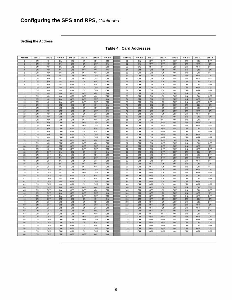
The SPS and RPS have jumper ports (see Figure 1) for the IDNet shield connection, Earth ground monitoring, and for city or relay module trouble activation. The SPS and RPS also require an address setting via DIP switch SW1. This section describes each setting.
P1: Earth Fault Monitor jumper. Position 1-2 enables Earth fault monitoring; Position 2-3 disables Earth fault monitoring. Set for [1-2] in all systems except those with TrueAlert Power Supply (TPS, 4100-5120/5121/5122) modules. Set for [2-3] in systems with TPS.
P2: (SPS only). IDNet Shield Connection Jumper. If the SPS IDNet outputs are being used, you may change P2 to configure the IDNet shield connection. Position 1-2 connects the shield to 0 V (default); Position 2-3 connects the shield to Earth ground.
P3 City/Relay Hardwired Trouble Jumper. Position 1-2 removes trouble monitoring on Relay 3 (default) of the 4100-6033 Alarm Relay Card; Position 2-3 activates the 4100-6031/6032 City Cards or the 4100-6033 Alarm Relay Card when the system microprocessor fails. Always use Position 2-3 for 4100-6031/6032 City Cards.
The SPS or RPS device address is set via DIP switch SW1, which is a bank of eight switches. From left to right (see below) these switches are designated as SW1-1 through SW1-8. The function of these switches is as follows:
SW1-1: This switch sets the baud rate for the internal 4100 communications line running between the card and the 4100 CPU. Set this switch to ON.
SW1-2 through SW1-8: These switches set the card’s address within the 4100 FACP. Refer to Table 4 for a complete list of the switch settings for all of the possible card addresses.
Note: You must set these switches to the value assigned to the card by the Programmer.
FigureTag FD9-246-01
1 8 7 6 5 4 3 2
Figure 3. DIP Switch SW1
The model 4100-5112 (SPS) and 4100-5126 (RPS) are required in jurisdictions, such as Canada, where depleted battery conditions are required, by local code, to result in power-down of the unit until AC power is restored. The system must also be programmed for depleted battery cutout, for each power supply.
Continued on next page
Configuring the SPS and RPS
Overview
Jumper Settings
Setting the Address
ON
OFF
DIP Switches SW1-2 through SW1-8 set the Card Address. Figure shows an Address of 3.
4100 Comm. Baud Rate. Switch (SW1-1)
Must Be Set to ON
9
Table 4. Card Addresses
Configuring the SPS and RPS, Continued
Setting the Address
Address SW 1-2 SW 1-3 SW 1-4 SW 1-5 SW 1-6 SW 1-7 SW 1-8 Address SW 1-2 SW 1-3 SW 1-4 SW 1-5 SW 1-6 SW 1-7 SW 1-8
1 ON ON ON ON ON ON OFF 61 ON OFF OFF OFF OFF ON OFF
2 ON ON ON ON ON OFF ON 62 ON OFF OFF OFF OFF OFF ON
3 ON ON ON ON ON OFF OFF 63 ON OFF OFF OFF OFF OFF OFF
4 ON ON ON ON OFF ON ON 64 OFF ON ON ON ON ON ON
5 ON ON ON ON OFF ON OFF 65 OFF ON ON ON ON ON OFF
6 ON ON ON ON OFF OFF ON 66 OFF ON ON ON ON OFF ON
7 ON ON ON ON OFF OFF OFF 67 OFF ON ON ON ON OFF OFF
8 ON ON ON OFF ON ON ON 68 OFF ON ON ON OFF ON ON
9 ON ON ON OFF ON ON OFF 69 OFF ON ON ON OFF ON OFF
10 ON ON ON OFF ON OFF ON 70 OFF ON ON ON OFF OFF ON
11 ON ON ON OFF ON OFF OFF 71 OFF ON ON ON OFF OFF OFF
12 ON ON ON OFF OFF ON ON 72 OFF ON ON OFF ON ON ON
13 ON ON ON OFF OFF ON OFF 73 OFF ON ON OFF ON ON OFF
14 ON ON ON OFF OFF OFF ON 74 OFF ON ON OFF ON OFF ON
15 ON ON ON OFF OFF OFF OFF 75 OFF ON ON OFF ON OFF OFF
16 ON ON OFF ON ON ON ON 76 OFF ON ON OFF OFF ON ON
17 ON ON OFF ON ON ON OFF 77 OFF ON ON OFF OFF ON OFF
18 ON ON OFF ON ON OFF ON 78 OFF ON ON OFF OFF OFF ON
19 ON ON OFF ON ON OFF OFF 79 OFF ON ON OFF OFF OFF OFF
20 ON ON OFF ON OFF ON ON 80 OFF ON OFF ON ON ON ON
21 ON ON OFF ON OFF ON OFF 81 OFF ON OFF ON ON ON OFF
22 ON ON OFF ON OFF OFF ON 82 OFF ON OFF ON ON OFF ON
23 ON ON OFF ON OFF OFF OFF 83 OFF ON OFF ON ON OFF OFF
24 ON ON OFF OFF ON ON ON 84 OFF ON OFF ON OFF ON ON
25 ON ON OFF OFF ON ON OFF 85 OFF ON OFF ON OFF ON OFF
26 ON ON OFF OFF ON OFF ON 86 OFF ON OFF ON OFF OFF ON
27 ON ON OFF OFF ON OFF OFF 87 OFF ON OFF ON OFF OFF OFF
28 ON ON OFF OFF OFF ON ON 88 OFF ON OFF OFF ON ON ON
29 ON ON OFF OFF OFF ON OFF 89 OFF ON OFF OFF ON ON OFF
30 ON ON OFF OFF OFF OFF ON 90 OFF ON OFF OFF ON OFF ON
31 ON ON OFF OFF OFF OFF OFF 91 OFF ON OFF OFF ON OFF OFF
32 ON OFF ON ON ON ON ON 92 OFF ON OFF OFF OFF ON ON
33 ON OFF ON ON ON ON OFF 93 OFF ON OFF OFF OFF ON OFF
34 ON OFF ON ON ON OFF ON 94 OFF ON OFF OFF OFF OFF ON
35 ON OFF ON ON ON OFF OFF 95 OFF ON OFF OFF OFF OFF OFF
36 ON OFF ON ON OFF ON ON 96 OFF OFF ON ON ON ON ON
37 ON OFF ON ON OFF ON OFF 97 OFF OFF ON ON ON ON OFF
38 ON OFF ON ON OFF OFF ON 98 OFF OFF ON ON ON OFF ON
39 ON OFF ON ON OFF OFF OFF 99 OFF OFF ON ON ON OFF OFF
40 ON OFF ON OFF ON ON ON 100 OFF OFF ON ON OFF ON ON
41 ON OFF ON OFF ON ON OFF 101 OFF OFF ON ON OFF ON OFF
42 ON OFF ON OFF ON OFF ON 102 OFF OFF ON ON OFF OFF ON
43 ON OFF ON OFF ON OFF OFF 103 OFF OFF ON ON OFF OFF OFF
44 ON OFF ON OFF OFF ON ON 104 OFF OFF ON OFF ON ON ON
45 ON OFF ON OFF OFF ON OFF 105 OFF OFF ON OFF ON ON OFF
46 ON OFF ON OFF OFF OFF ON 106 OFF OFF ON OFF ON OFF ON
47 ON OFF ON OFF OFF OFF OFF 107 OFF OFF ON OFF ON OFF OFF
48 ON OFF OFF ON ON ON ON 108 OFF OFF ON OFF OFF ON ON
49 ON OFF OFF ON ON ON OFF 109 OFF OFF ON OFF OFF ON OFF
50 ON OFF OFF ON ON OFF ON 110 OFF OFF ON OFF OFF OFF ON
51 ON OFF OFF ON ON OFF OFF 111 OFF OFF ON OFF OFF OFF OFF
52 ON OFF OFF ON OFF ON ON 112 OFF OFF OFF ON ON ON ON
53 ON OFF OFF ON OFF ON OFF 113 OFF OFF OFF ON ON ON OFF
54 ON OFF OFF ON OFF OFF ON 114 OFF OFF OFF ON ON OFF ON
55 ON OFF OFF ON OFF OFF OFF 115 OFF OFF OFF ON ON OFF OFF
56 ON OFF OFF OFF ON ON ON 116 OFF OFF OFF ON OFF ON ON
57 ON OFF OFF OFF ON ON OFF 117 OFF OFF OFF ON OFF ON OFF
58 ON OFF OFF OFF ON OFF ON 118 OFF OFF OFF ON OFF OFF ON
59 ON OFF OFF OFF ON OFF OFF 119 OFF OFF OFF ON OFF OFF OFF
60 ON OFF OFF OFF OFF ON ON

10
The SPS and RPS get their power from the Power Distribution Module (PDM). The PDM takes power directly from a dedicated AC line and the two backup batteries, and distributes power to each bay in the cabinet.
The power distribution module (PDM) connects to the SPS, RPS, or XPS in each bay. One PDM is used per back box. Use the instructions below to properly connect the PDM to each bay. 1. Route the Black and White AC power wires to the supplied ferrite bead. Loop the wires
twice through the bead as shown below:
Figure 4. Wire Loops through Ferrite Bead
2. Wire 120/220/230/240 VAC to the PDM, keeping AC wires at least one inch away from all other wires. AC power must stay in the right side of the cabinet, in the non-power-limited area.
3. Connect batteries to P5 on the PDM using Harness 734-015.
Continued on next page
Internal Wiring
Overview
Power Distribution Module Connections
To AC Breaker
To PDM

11
4. Connect the PDM to the SPS or RPS using Harness 734-012 (734-013 for 220/230/240VAC versions).
Feed Red and Black wires through the side rail to the front of the SPS or RPS to prevent wire damage when the front panel is inserted.
Connect the separate Red and Black wires (with Yellow female terminations) to plugs P5 (Black) and P4 (Red) on the SPS or RPS.
Connect the White and Black wires, which terminate together in a White snap-on connector, to the bulkhead connector at the bottom of the SPS or RPS assembly, as shown below.
P1
P2
P3
P4
P5
Figure 5. SPS Assembly Connector
Internal Wiring, Continued
Power Distribution Module Connections
SPS
120 V TO TRANSFORMER THROUGH BULKHEAD CONNECTOR
SPS ASSEMBLY (CPU bay assembly
shown)
RED WIRE
BLACK WIRE
P4 P5
Bulkhead connector BATTERY HARNESS
FUSED AT 15 A
HARNESS 734-015 TO 24 V BATTERY
HARNESS (734-012)
(734-013)*
GROUND
BACK BOX GROUND SCREW
*220/230/240VAC PART NUMBERS APPEAR IN ITALICS.
220
VA
C
230
VA
C
240
VA
C
NE
UT
50/60 Hz 2 A
566-248 220/230/240VAC PDM TERMINAL
BLOCK
Second bulkhead connector here in 220/230/240VAC versions
120 V NEUTRAL
120 VAC 60 Hz, 4 A
FERRITE BEAD
PDM (566-246) (or 566-248; see below)*

12
The SPS and RPS provide three outputs for reverse-polarity notification appliance circuits. This section describes basic NAC wiring from the SPS and RPS to 4100-compatible appliances.
The SPS and RPS supports both Class A and Class B NAC wiring.
Class A wiring allows appliances to communicate with the SPS or RPS even in the event of an open circuit somewhere in the loop. Class A wiring requires that two wires are routed from the SPS/RPS to each appliance, and then back again to the SPS or RPS.
The table below lists the maximum distances from the SPS or RPS to the last appliance in a Class A configuration, depending on wire gauge and current. Use this table to calculate wire distances for your application if you are using Class A wiring.
Table 5. Class A Wiring Distances
Alarm Current @ 24 V
Max Distance w/ 18 AWG
(0.8231 mm2)
Max Distance w/ 16 AWG (1.309 mm2)
Max Distance w/ 14 AWG (2.081 mm2)
Max Distance w/ 12 AWG (3.309 mm2)
DC Resistance
0.25 A 420 ft. (128 m) 667 ft. (203 m) 1,063 ft. (324 m) 1,691 ft. (515 m) 6 Ohms
0.50 A 210 ft. (64 m) 334 ft. (102 m) 532 ft. (162 m) 845 ft. (258 m) 3 Ohms
0.75 A 140 ft. (43 m) 222 ft. (68 m) 354 ft. (108 m) 564 ft. (172 m) 2 Ohms
1 A 105 ft. (32 m) 167 ft. (51 m) 266 ft. (81 m) 423 ft. (129 m) 1.5 Ohms
1.25 A 84 ft. (26 m) 133 ft. (41 m) 213 ft. (65 m) 338 ft. (103 m) 1.2 Ohms
1.50 A 70 ft. (21 m) 111 ft. (34 m) 177 ft. (54 m) 282 ft. (86 m) 1 Ohm
1.75 A 60 ft. (18 m) 95 ft. (29 m) 152 ft. (46 m) 242 ft. (74 m) 0.86 Ohm
2 A 53 ft. (16 m) 83 ft. (25 m) 133 ft. (41 m) 211 ft. (64 m) 0.75 Ohm
2.25 A 47 ft. (14 m) 74 ft. (23 m) 118 ft. (36 m) 188 ft. (57 m) 0.67 Ohm
2.50 A 42 ft. (13 m) 67 ft. (20 m) 106 ft. (32 m) 169 ft. (51 m) 0.60 Ohm
2.75 A 38 ft. (12 m) 61 ft. (19 m) 97 ft. (30 m) 154 ft. (47 m) 0.55 Ohm
3 A 35 ft. (11 m) 56 ft. (17 m) 89 ft. (27 m) 141 ft. (43 m) 0.50 Ohm
Notes:
Max Distance = distance from SPS/RPS to last appliance.
This table is calculated at 50 degrees Centigrade (120 degrees Fahrenheit). If you are installing in locations that could be exposed to higher temperatures, refer to National Electrical Code (NEC) Table 8.
Distances are based on a 3V drop and take into account the worst-case panel output voltage.
If Circuit Integrity (CI) cable is used instead of housing cable in a fire rated enclosure, reduce wiring distances by 38 feet (12 m) for every 10 feet (3 m) of potential fire exposure. The direct exposure of the CI cable to flames increases the resistance of the cable. Therefore, you must reduce the cable distance to account for the potential exposure of the CI cable to fire.
If Wheelock appliances employing EZ Mount SNAP bases are used, reduce the wiring distance and wiring resistance by:
12 gauge wire: 3.5 feet per appliance, 0.0125 Ohms per appliance 14 gauge wire: 2.2 feet per appliance, 0.0125 Ohms per appliance 16 gauge wire: 1.4 feet per appliance, 0.0125 Ohms per appliance
18 gauge wire: 0.9 feet per appliance, 0.0125 Ohms per appliance
Continued on next page
NAC Field Wiring
Overview
NAC Wiring Styles
Class A NAC Wiring Table

13
The table below lists the maximum distances from the SPS or RPS to the last appliance in a Class B configuration, depending on wire gauge and current. Use this table to calculate wire distances for your application if you are using Class B wiring.
Table 6. Class B Wiring Distances
Alarm Current @ 24 V
Max Distance w/ 18 AWG
(0.8231 mm2)
Max Distance w/ 16 AWG
(1.309 mm2)
Max Distance w/ 14 AWG (2.081 mm2)
Max Distance w/ 12 AWG
(3.309 mm2)
DC Resistance
0.25 A 840 ft. (256 m) 1,335 ft. (407 m) 2,126 ft. (648 m) 3,382 ft. (1,031 m) 12 Ohms
0.50 A 420 ft. (128 m) 667 ft. (203 m) 1,063 ft. (324 m) 1,691 ft. (515 m) 6 Ohms
0.75 A 280 ft. (85 m) 445 ft. (136 m) 709 ft. (216 m) 1,127 ft. (344 m) 4 Ohms
1 A 210 ft. (64 m) 334 ft. (102 m) 532 ft. (162 m) 845 ft. (258 m) 3 Ohms
1.25 A 168 ft. (51 m) 267 ft. (81 m) 425 ft. (130 m) 676 ft. (206 m) 2.4 Ohms
1.50 A 140 ft. (43 m) 222 ft. (68 m) 354 ft. (108 m) 564 ft. (172 m) 2 Ohms
1.75 A 120 ft. (37 m) 191 ft. (58 m) 304 ft. (93 m) 483 ft. (147 m) 1.71 Ohms
2 A 105 ft. (32 m) 167 ft. (51 m) 266 ft. (81 m) 423 ft. (129 m) 1.5 Ohms
2.25 A 93 ft. (28 m) 148 ft. (45 m) 236 ft. (72 m) 376 ft. (115 m) 1.33 Ohms
2.50 A 84 ft. (26 m) 133 ft. (41 m) 213 ft. (65 m) 338 ft. (103 m) 1.2 Ohms
2.75 A 76 ft. (23 m) 121 ft. (37 m) 193 ft. (59 m) 307 ft. (94 m) 1.09 Ohms
3 A 70 ft. (21 m) 111 ft. (34 m) 177 ft. (54 m) 282 ft. (86 m) 1 Ohm
Notes:
Max Distance = distance from SPS or RPS to last appliance.
This table is calculated at 50 degrees Centigrade (120 degrees Fahrenheit). If you are installing in locations that could be exposed to higher temperatures, refer to NEC Table 8.
Distances are based on a 3 V drop, and take into account the worst-case panel output voltage.
If Circuit Integrity (CI) cable is used instead of housing cable in a fire rated enclosure, reduce wiring distances by 38 feet (12 m) for every 10 feet (3 m) of potential fire exposure. The direct exposure of the CI cable to flames increases the resistance of the cable. Therefore, you must reduce the cable distance to account for the potential exposure of the CI cable to fire.
Continued on next page
NAC Field Wiring, Continued
Class B NAC Wiring Table

14
All wiring is 18 AWG (0.8231 mm2) (minimum) to 12 AWG (3.309 mm2) (maximum).
All wiring is supervised and power-limited.
The maximum alarm current is 3 A per circuit. The supervisory current is 2.03 mA at 24 VDC.
The nominal voltage rating is 24 VDC, 2 V p-p ripple (maximum).
The total available current from the SPS or RPS is 9 A unless it is used for regulated 24 VDC notification appliances, where the SPS/RPS is rated for 4 Amps notification current and 1Amp for other uses. Total auxiliary power current is 5 A (1 Amp for regulated 24 VDC), and rated at 2 A per circuit. Any current used for card power by modules plugged into the PDI, as well as any auxiliary 24 VDC current, must be deducted from the total available current.
All wiring that leaves the building requires overvoltage protection. Install module 2081-9044 (3 A) or 2081-9028 (1/4 A) inside a UL-Listed electrical box wherever wire enters or exits the building. When using the 2081-9044, the maximum alarm current is reduced to 1/4 A for that part of the circuit downstream of the module. Refer to 574-805 for installation instructions of 2081-9028 modules or to 574-832 for installation instructions of 2081-9044 modules.
Terminal designations “+” and “-” are for the alarm state.
A maximum of 70 appliances can be supported per circuit.
For CE systems, use ferrite beads as shown in each figure. 4100-5129 includes three ferrite beads, order as needed. Loop wires once through the ferrite bead(s) as shown below:
Figure 6. Loop through Ferrite Bead
If Wheelock appliances employing EZ Mount SNAP bases are used, reduce the wiring distance and wiring resistance by:
12 gauge wire: 7 feet per appliance, 0.025 Ohms per appliance 14 gauge wire: 4.4 feet per appliance, 0.025 Ohms per appliance 16 gauge wire: 2.8 feet per appliance, 0.025 Ohms per appliance 18 gauge wire: 1.8 feet per appliance, 0.025 Ohms per appliance
Continued on next page
NAC Field Wiring, Continued
Guidelines

15
Compatible appliances for NACs are shown in Table 7:
Table 7. Compatible Appliances and Accessories (for Special Application NACs)
P/N Description P/N Description P/N Description
4904-9168 V/O 15CD RED FREE-RUN TNA 4906-9102 V/O 15/30/75/110cd C/M RED TNA 4903-9253 A/V 24VDC 30CD RED HOR F/S
4904-9171 V/O 15CD WHITE FREE-RUN TNA 4906-9103 V/O 15/30/75/110cd W/M WHT TNA 4903-9254 A/V 24V 110CD RED HOR F/S
4904-9176 V/O 24VDC 15CD RED VER F/S 4906-9104 V/O 15/30/75/110cd C/M WHT TNA 4903-9255 A/V 24VDC 15CD RED VER F/S
4904-9177 V/O 24VDC 15CD WHT VER F/S 4903-9356 S/V 15CD RED 25/70V TNA 4903-9256 A/V 24V 110CD RED VER F/S
4904-9178 V/O 24VDC 15CD RED HORIZ F/S 4903-9359 S/V 15CD WHITE 25/70V TNA 4903-9257 A/V 24VDC 15CD WHT HOR F/S
4904-9183 V/O 24VDC 15CD RED CEIL F/S 4903-9150 S/V 24VDC 15CD RED HORIZ F/S 4903-9258 A/V 24VDC 30CD WHT HOR F/S
4904-9331 V/O 15CD RED SYNC TNA 4903-9153 S/V 24VDC 15CD RED VER F/S 4903-9417 A/V 15CD RED SYNC TNA
4904-9342 V/O 15CD WHITE SYNC TNA 4903-9193 S/V 24VDC 15CD WHT HORIZ F/S 4903-9418 A/V 75CD RED SYNC TNA
4904-9345 V/O 24VDC 15CD WHT PLAIN F/S 4903-9196 S/V15CD RND 4903-9419 A/V 110CD RED SYNC TNA
4904-9174 V/O 24VDC 30CD RED VER F/S 4903-9148 S/V 24VDC 30CD RED HORIZ F/S 4903-9425 A/V 15CD RED STD TNA
4904-9180 V/O 24VDC 30CD RED HORIZ F/S 4903-9194 S/V 24VDC 30CD WHT HORIZ F/S 4903-9426 A/V 75CD RED STD TNA
4904-9184 V/O 24VDC 30CD RED CEIL F/S 4903-9197 S/V, 30CD, RND TNA 4903-9427 A/V 110CD RED STD TNA
4904-9346 V/O 24VDC 30CD WHT PLAIN F/S 4903-9357 S/V 75CD RED 25/70V TNA 4903-9428 A/V 15CD WHITE SYNC TNA
4904-9169 V/O 75CD RED FREE-RUN TNA 4903-9360 S/V 75CD WHITE 25/70V TNA 4903-9429 A/V 75CD WHITE SYNC TNA
4904-9172 V/O 75CD WHITE FREE-RUN TNA 4903-9358 S/V 110CD RED 25/70V TNA 4903-9430 A/V 110CD WHITE SYNC TNA
4904-9332 V/O 75CD RED SYNC TNA 4903-9361 S/V 110CD WHITE 25/70V TNA 4903-9431 A/V 15CD WHITE STD TNA
4904-9343 V/O 75CD WHITE SYNC TNA 4903-9198 S/V 110CD, RND TNA 4903-9432 A/V 75CD WHITE STD TNA
4904-9170 V/O 110CD RED FREE-RUN TNA 4906-9151 S/V 15/30/75/110cd W/M RED TNA 4903-9433 A/V 110CD WHITE STD TNA
4904-9173 V/O 110CD WHITE FREE-RUN TNA 4906-9153 S/V 15/30/75/110cd W/M WHT TNA 4906-9127 A/V 15/30/75/110cd W/M RED
4904-9175 V/O 24VDC 110CD RED VER F/S 4906-9154 S/V 15/30/75/110cd C/M WHT TNA 4906-9129 A/V 15/30/75/110cd W/M WHT
4904-9181 V/O 24VDC 110CD WHT VER F/S 4901-9820 HORN 24VDC RED TNA 4906-9128 A/V 15/30/75/110cd C/M RED
4904-9182 V/O 24VDC 110CD RED HOR F/S 4901-9822 HORN 24VDC RED 4906-9130 A/V 15/30/75/110cd C/M WHT
4904-9185 V/O 24VDC 110CD RED CEIL F/S 4009-9201 NAC EXTENDER 120VAC, IDNET 4905-9815 SMARTSYNC ADAPTER, TNA
4904-9333 V/O 110CD RED SYNC TNA 4009-9301 NAC EXTENDER, 240VAC, IDNET 4905-9938 SMARTSYNC CTL MODULE
4904-9344 V/O 110CD WHITE SYNC TNA 4009-9401 4009 T/A ADDR CONTROLLER 4090-9005 SRP
4906-9101 V/O 15/30/75/110cd W/M RED TNA 4903-9252 A/V 24VDC 15CD RED HOR F/S 4090-9006 SRP w/ENCLOSURE
4906-9105 V/O Weatherproof W/M, RED 4906-9113 V/O Weatherproof W/M, (Can) RED 4906-9132 A/V Weatherproof, W/M, WHT
4906-9106 V/O Weatherproof W/M, WHT 4906-9131 A/V Weatherproof, W/M, RED 4906-9143 A/V Weatherproof, W/M, RED
4906-9109 HiCandela W/M V/O, RED 4906-9139 HiCandela W/M A/V, RED 4906-9140 HiCandela C/M A/V, RED
4906-9111 HiCandela W/M V/O, WHITE 4906-9141 HiCandela W/M A/V, WHITE 4906-9142 HiCandela C/M A/V, WHITE
4906-9110 HiCandela C/M V/O, WHITE 4906-9112 HiCandela C/M V/O, RED
Continued on next page
NAC Field Wiring, Continued
Guidelines

16
NAC Field Wiring, Continued
Table 8. COOPER WHEELOCK APPLIANCES (Compatible with 4100U/4100ES SPS/RPS Wheelock Protocol for Special Applications)
SYNCHRONIZING HORN STROBES
AS-241575W AS Series Horn Strobe. 24V, 15/75Cd, Wall Mount
AS-24MCW AS Series Horn Strobe. 24V, Multi-Cd, Wall Mount
AS-24MCC AS Series Horn Strobe. 24V, Multi-Cd, Ceiling Mount
AS-24MCWH AS Series Horn Strobe. 24V, Multi-High-Cd, Wall Mount
AS-24MCCH AS Series Horn Strobe. 24V, Multi-High-Cd, Ceiling Mount
ASWP-2475W, AS Series WP Horn Strobe. 24V, 30Cd, Wall or Ceiling Mount
ASWP-24MCWH AS Series WP Horn Strobe. 24V, Multi-High-Cd, Wall Mount
ASWP-24MCCH AS Series WP Horn Strobe. 24V, Multi-High-Cd, Ceiling Mount
ASA-24MCW, ASB-24MCW AS Series Horn Strobe. 24V, Multi-Cd, Wall Mount. Amber/Blue
ASA-24MCC, ASB-24MCC AS Series Horn Strobe. 24V, Multi-Cd, Ceiling Mount. Amber/Blue
HSR HN STR, Red, 2-wire, Wall, 12/24V, 3dB, 8CD, 5 Mount
HSW HN STR, White, 2-wire, Wall, 12/24V, 3dB, 8CD, 5 Mount
HSRS HN STR, Silver Red, 2-wire, Wall, 12/24V, 3dB, 8CD, 5 Mount
HSWS HN STR, Silver White, 2-wire, Wall, 12/24V, 3dB, 8CD, 5 Mount
HSRC HN STR, Red, 2-wire, Ceiling Mount, 12/24V, 3dB, 8 Cd, 5 Mount
HSWC HN STR, White, 2-wire, Ceiling Mount, 12/24V, 3dB, 8 Cd, 5 Mount
HSRCS HN STR, Silver red, 2-wire, Ceiling Mount, 12/24V, 3dB, 8 Cd, 5 Mount
HSWCS HN STR, Silver white, 2-wire, Ceiling Mount, 12/24V, 3dB, 8 Cd, 5 Mount
HS4-241575W HS4 Series Horn Strobe. 24V, 15/75Cd, Wall Mount
HS4-24MCW HS4 Series Horn Strobe. 24V, Multi-Cd, Wall Mount
HS4-24MCWH HS4 Series Horn Strobe. 24V, Multi-High-Cd, Wall Mount
HS4-24MCC HS4 Series Horn Strobe. 24V, Multi-Cd, Ceiling Mount
NS-241575W NS Series Horn Strobe. 24V, 15/75Cd, Wall Mount
NS-24MCW NS Series Horn Strobe. 24V, Multi-Cd, Wall Mount
NS-24MCC NS Series Horn Strobe. 24V, Multi-Cd, Ceiling Mount
NS-24MCCH NS Series Horn Strobe. 24V, Multi-High-Cd, Ceiling Mount
ZNS-MCW ZNS Series Horn Strobe. 24V, Multi-Cd, Wall Mount
ZNS-MCWH ZNS Series Horn Strobe. 24V, Multi-High-Cd, Wall Mount
ZNS-24MCC ZNS Series Horn Strobe. 24V, Multi-Cd, Ceiling Mount
ZNS-24MCCH ZNS Series Horn Strobe. 24V, Multi-High-Cd, Ceiling Mount
SYNCHRONIZING STROBES
RSS-241575W RSS Series Strobe. 24V, 15/75Cd, Wall Mount
RSSP-241575W RSSP Series Strobe. 12V or 24V, 15/75Cd, Wall Mount
RSS-24MCW, RSSP-24MCW RSS/RSSP Series Strobe. 24V, Multi-Cd, Wall Mount
RSS-24MCWH, RSSP-24MCWH RSS/RSSP Series Strobe. 24V, Multi-High-Cd, Wall Mount
RSS-24MCC, RSS-24MCCR RSS Series Strobe. 24V, Multi-Cd, Ceiling Mount (R=Round)
RSS-24MCCH, RSS-24MCCHR RSS Series Strobe. 24V, Multi-High-Cd, Ceiling Mount (R=Round)
RSSR-2415W, RSSR-2415C RSS Series Strobe. 24V, 15Cd, Red, Wall or Ceiling Mount
RSSR-2475W, RSSR-2475C RSS Series Strobe. 24V, 75Cd, Red, Wall or Ceiling Mount
RSSR-24110C RSS Series Strobe. 24V, 110Cd, Red, Ceiling Mount
RSSA-24110W, RSSB-24110W,
RSSG-24110W, RSSR-24110W RSS Series Strobe. 24V, 110Cd, Wall Mount. Amber/Blue/Green/Red.
RSSA-24MCC, RSSB-24MCC,
RSSG-24MCC, RSSR-24MCC RSS Series Strobe. 24V, Multi-Cd, Ceiling Mount. Amber/Blue/Green/Red.
RSSA-24MCCH, RSSB-24MCCH,
RSSG-24MCCH, RSSR-24MCCH RSS Series Strobe. 24V, Multi-High-Cd, Ceiling Mount. Amber/Blue/Green/Red.
RSSPA-24MCC RSSP Series Strobe. 24V, Multi-Cd, Ceiling Mount. Amber

17
NAC Field Wiring, Continued
Table 8. COOPER WHEELOCK APPLIANCES (Compatible with 4100U/4100ES SPS/RPS Wheelock Protocol for Special Applications)
RSSWPA-2475W RSS Series WP Strobe. 24V, Wall Mount. Amber
RSSWPA-24MCCH,
RSSWPB-24MCCH,
RSSWPG-24MCCH,
RSSWPR-24MCCH RSS Series WP Strobe. 24V, Multi-High-Cd, Ceiling Mount.Amber/Blue/Green/Red.
RSSWP-2475W, RSSWP-2475C RSS Series WP Strobe. 24V, 30Cd, Wall or Ceiling Mount
RSSWP-24MCWH RSS Series WP Strobe. 24V, Multi-High-Cd, Wall Mount
RSSWP-24MCCH RSS Series WP Strobe. 24V, Multi-High-Cd, Ceiling Mount
STR STR, red, 2-wire, Wall, 12/24V, 8CD, 5 Mount
STW STR, white, 2-wire, Wall, 12/24V, 8CD, 5 Mount
STRS STR, silver red, 2-wire, Wall, 12/24V, 8CD, 5 Mount
STWS STR, silver white, 2-wire,Wall, 12/24V, 8CD, 5 Mount
STRC STR, Red, 2-wire, Ceiling Mount, 12/24V, 8 Cd, 5 Mount
STWC STR, White, 2-wire, Ceiling Mount, 12/24V, 8 Cd, 5 Mount
STRCS STR, Silver red, 2-wire, Ceiling Mount, 12/24V, 8 Cd, 5 Mount
STWCS STR, Silver white, 2-wire, Ceiling Mount, 12/24V, 8 Cd, 5 Mount
ZRS-MCW ZRS Series Strobe. 24V, Multi-Cd, Wall Mount
ZRS-MCWH ZRS Series Strobe. 24V, Multi-High-Cd, Wall Mount
ZRS-24MCC ZRS Series Strobe. 24V, Multi-Cd, Ceiling Mount
ZRS-24MCCH ZRS Series Strobe. 24V, Multi-High-Cd, Ceiling Mount
APPLIANCES WITH SYNCHRONIZING STROBES
(Only Strobe portion compatible with 4008 Wheelock Protocol for Special Applications)
AMT-241575W,AMT-241575W-NYC AMT Series Multi-Tone Horn Strobe. 24V, 15/75Cd, Wall Mount
AMT-24MCW AMT Series Multi-Tone Horn Strobe. 24V, Multi-Cd, Wall Mount
MT-241575W MT Series MT Horn Strobe. 24V, 15/75Cd, Wall Mount.
MT-24MCW MT Series Multi-Tone Horn Strobe. 24V, Multi-Cd, Wall Mount
MTWP-2475W,MTWP-2475C MTWP Series MT Horn Strobe. 24V, 30Cd, Wall or Ceiling Mount
MTWP-24MCWH MTWP Series MT Horn Strobe. 24V, Multi-High-Cd, Wall Mount
MTWP-24MCCH MTWP Series MT Horn Strobe. 24V, Multi-High-Cd, Ceiling Mount
MTWPA-2475W,MTWPB-2475W
MTWPG-2475W,MTWPR-2475W MTWP Series Multi-Tone Horn Strobe. 24V, Wall Mount.
Amber/Blue/Green/Red
MTA-24MCCH,MTB-24MCCH,
MTG-24MCCH,MTR-24MCCH MT Series Multi-Tone Horn Strobe. 24V, Multi-High-Cd, Wall Mount
Amber/Blue/Green/Red
MTWPA-24MCCH,
MTWPB-24MCCH,
MTWPG-24MCCH,
MTWPR-24MCCH MTWP Series Multi-Tone Horn Strobe. 24V, Multi-High-Cd, Wall Mount.Amber/Blue/Green/Red
ET70WP-2475W,ET70WP-2475C ET70WP Series Speaker Strobe. 24V, 30Cd, Wall or Ceiling Mount
ET70WP-24185W ET70WP Series Speaker Strobe. 24V, 185Cd, Wall Mount
ET70WP-24177C ET70WP Series Speaker Strobe. 24V, 177Cd, Ceiling Mount
ET70WPA-2475 ET70WP Series Speaker Strobe. 24V, Wall or Ceiling Mt. Amber
CH70-241575W CH70 Series Chime Strobe. 24V, 15/75Cd, Wall Mount
CH70-24MCW CH70 Series Chime Strobe. 24V, Multi-Cd, Wall Mount
CH90-24MCC CH90 Series Chime Strobe. 24V, Multi-Cd, Ceiling Mount
CH70-24MCWH CH70 Series Chime Strobe. 24V, Multi-High-Cd, Wall Mount

18
NAC Field Wiring, Continued
Table 8. COOPER WHEELOCK APPLIANCES (Compatible with 4100U/4100ES SPS/RPS Wheelock Protocol for Special Applications)
CH90-24MCCH CH90 Series Chime Strobe. 24V, Multi-High-Cd, Ceiling Mount
E50-241575W E50 Series Speaker Strobe. 24V, 15/75Cd, Wall Mount
E50-24MCW E50 Series Speaker Strobe. 24V, Multi-Cd, Wall Mount
E50-24MCWH E50 Series Speaker Strobe. 24V, Multi-High-Cd, Wall Mount
E50A-24MCC,E50B-24MCC E50 Series Speaker Strobe. 24V, Multi-Cd, Ceiling Mt. Amber/Blue
E60-24MCW E60 Series Speaker Strobe. 24V, Multi-Cd, Wall Mount
E60-24MCWH E60 Series Speaker Strobe. 24V, Multi-High-Cd, Wall Mount
E60-24MCC E60 Series Speaker Strobe. 24V, Multi-Cd, Ceiling Mount
E60-24MCCH E60 Series Speaker Strobe. 24V, Multi-High-Cd, Ceiling Mount
E70-241575W E70 Series Speaker Strobe. 24V, 15/75Cd, Wall Mount
E70-24MCW E70 Series Speaker Strobe. 24V, Multi-Cd, Wall Mount
E70-24MCWH E70 Series Speaker Strobe. 24V, Multi-High-Cd, Wall Mount
E70-24MCC,E90-24MCC E70/E90 Series Speaker Strobe. 24V, Multi-Cd, Ceiling Mount
E90-24MCCH E90 Series Speaker Strobe. 24V, Multi-High-Cd, Ceiling Mount
E60A-24MCC,E70A-24MCC,
E70B-24MCC,E90A-24MCC,
E90B-24MCC E60/E70/E90 Series Speaker Strobe. 24V, Multi-Cd, Ceiling Mount.Amber/Blue
ET70-241575W,ET90-241575W ET70/ET90 Series Speaker Strobe. 24V, 15/75Cd, Wall Mount
ET70-24MCW ET70 Series Speaker Strobe. 24V, Multi-Cd, Wall Mount
ET70-24MCWH ET70 Series Speaker Strobe. 24V, Multi-High-Cd, Wall Mount
ET70-24MCC,ET90-24MCC ET70/ET90 Series Speaker Strobe. 24V, Multi-Cd, Ceiling Mount
ET70WPG-2475,ET70WPG-2475,
ET70WPG-2475,ET70WPB-2475W,
ET70WPG-2475W,ET70WPR-2475W ET70WP Series Speaker Strobe. 24V, Wall or Ceiling Mt. Green, Blue, Red
ET90-24MCCH ET90 Series Speaker Strobe. 24V, Multi-High-Cd, Ceiling Mount
ET80-241575W ET80 Series Speaker Strobe. 24V, 15/75Cd, Wall Mount
ET80-24MCW ET80 Series Speaker Strobe. 24V, Multi-Cd, Wall Mount
ET80-24MCWH ET80 Series Speaker Strobe. 24V, Multi-High-Cd, Wall Mount
S8-24MCC S8 Series Speaker Strobe. 24V, Multi-Cd, Ceiling Mount
S8-24MCCH S8 Series Speaker Strobe. 24V, Multi-High-Cd, Ceiling Mount
SA-S70-24MCW SA-S70 Series Amp-Speaker Strobe. 24V, Multi-Cd, Wall Mount
SA-S90-24MCC SA-S90 Series Amp-Speaker Strobe. 24V, Multi-Cd, Ceiling Mount
SYNCHRONIZING HORNS
AH-24 AH Series Horn. 24V
AH-24WP AH Series Weatherproof Horn. 12V or 24V
HNR Horn, red, 2-wire, Wall, 12/24V, 3dB, 5 Mount
HNW Horn, white, 2-wire, Wall, 12/24V, 3dB, 5 Mount
HNRS Horn, silver red, 2-wire, Wall, 12/24V, 3dB, 5 Mount
HNWS Horn, silver white, 2-wire, Wall, 12/24V, 3dB, 5 Mount
HS-24 HS Series Horn. 24V
HNRC Horn, Red, 2-wire, Ceiling Mount, 12/24V, 3dB, 5 Mount
HNWC Horn, White, 2-wire, Ceiling Mount, 12/24V, 3dB, 5 Mount
HNRCS Horn, Silver red, 2-wire, Ceiling Mount, 12/24V, 3dB, 5 Mount
HNWCS Horn, Silver white, 2-wire, Ceiling Mount, 12/24V, 3dB, 5 Mount
MIZ-24S MIZ Series Horn. 24V
NH-12/24, NH-12/24R NH Series Horn. 12/24V (R=Round)
ZNH ZNH Series Horn. 12/24V

19
NAC Field Wiring, Continued
Table 8. COOPER WHEELOCK APPLIANCES (Compatible with 4100U/4100ES SPS/RPS Wheelock Protocol for Special Applications)
CODED AUDIBLE APPLIANCES
AMT-12/24, AMT-12/24-NYC AMT Series, Multi-tone horn, 12/24V, Wall or Ceiling Mount
CH70, CH90 CH70/CH90 Series chime, 24V, Wall or Ceiling Mount
CSX10-24-DC, CSXG10-24-DC CSX SeriesBell, 24V, Wall Mount
MT-12/24, MT4-12/24 MT Series Multi-tone horn, 12/24V, Wall or Ceiling Mount
NON-SYNCHRONIZING APPLIANCES
MB-G6-24, MB-G10-24 MB SeriesBell, 24V, Wall Mount

20
The Notification Appliance Circuits on the SPS or RPS are rated for Special Application and for regulated 24Vdc operation per UL864, 9th Edition. When used with the Notification Appliances listed in Table 7 or Table 8, each NAC is rated for 3A, and total SPS capacity is rated at 9A. This rating is the UL864 Special Application rating. Appliances listed in Table 7 and in Table 8 are synchronized per UL864, between all NACs on the SPS, and any NACs on an SPS, RPS or XPS within the same 4100U/4100ES system. This does not apply if appliances are mixed from both tables. Appliances from Table 7 will be 1/2 second out of audible sync with appliances from table 8 in the same system. All appliances any given SPS, RPS or XPS must be from either Table 7 or Table 8, mixing of appliances from both tables is not possible within a power supply.
For use with Notification Appliances not listed in Table 7 or Table 8, each circuit is rated for 2A maximum, with a total Notification Appliance load of 4A per SPS. This rating is the UL 864 Regulated 24Vdc rating. Synchronization of strobes and other appliances requires use of the associated, Listed, compatible Synchronization Module. Consult supplier of Notification Appliances for synchronization limits and details.
Non-pulsing, linear-type Notification Appliances, such as horns or bells may be used up to the full rating (3A for each NAC, 9A total for the SPS).
NAC Field Wiring, Continued
Guidelines

21
To connect the RPS or SPS to reverse-polarity, non-addressable notification appliances using Class A wiring, read the following instructions and refer to the figure below. 1. Route wire (between 12 [3.309 mm2] and 18 AWG [0.8231 mm2]) from the “B+” and “B-”
outputs on TB2 of the SPS to the appropriate inputs on a peripheral notification appliance. Use NAC1, NAC2, or NAC3.
2. Route wire from the first appliance to the next one. Repeat for each appliance.
3. Route wire from the last appliance to the A+ and A- inputs on the same NAC circuit of TB1 of the SPS or RPS.
4. Repeat Steps 1 through 3 for each NAC output you want to use.
5. Leave the factory-installed 10 K, 1/2 W, brown/black/orange resistor on each unused circuit. The circuit must connect “B+” to “B-” terminals. No external end-of-line resistor is needed for circuits in use.
P1321
B+ B- A+ A-
TYPICALAPPLIANCE
RED
RED
RED
NAC1
B+ B- A+ A-
NAC1
B+ B- A+ A-
NAC1
LED1 LED2 LED3
TYPICALAPPLIANCE
BLK
BLK
BLK
NAC2 NAC3
Figure 7. Class A NAC Wiring
Continued on next page
NAC Field Wiring, Continued
Class A NAC Wiring
12 AWG (3.309 mm2) to 18 AWG (0.8231 mm2)
IMPORTANT: Conductors must test free of all grounds.
You must have the EOL Resistor (10 K Ohm, 1/2 W; Brown/Black/Orange) on unused circuits
NAC2 NAC3
Ferrite beads required for
CE compliance. Use Kit 4100-5129.

22
To connect the SPS to appliances using Class B wiring, read the following instructions and refer to the figure below. 1. Route wire (between 12 [3.309 mm2] and 18 AWG [0.8231 mm2]) from the “B+” and “B-”
outputs on TB2 of the SPS to the appropriate inputs on a peripheral notification appliance. Use NAC1, NAC2, or NAC3.
2. Route wire from the first appliance to the next one. “T” tapping is not allowed. Repeat for each appliance.
3. Route wire from the last appliance to the EOLR harness (10K ohm, 1/2W: P/N 733-894, PID# 4081-9008).
4. Repeat Steps 1 through 3 for each NAC output you want to use.
5. Leave the factory-installed 10 K, 1/2 W, brown/black/orange resistor on each unused circuit. The circuit must connect “B+” to “B-” terminals.
The illustration below shows Class B wiring.
P1321
B+ B- A+ A-
TYPICALAPPLIANCE
RED BLK
NAC1
B+ B- A+ A-
NAC1
B+ B- A+ A-
NAC1
LED1 LED2 LED3
TYPICALAPPLIANCE
10K 1/2W (133-894)
NAC2 NAC3
RED RED
RED RED
Figure 8. Class B Wiring
Notes:
Notification appliances are rated per individual nameplate label.
Maintain correct polarity on terminal connections. Do not loop wires under terminals.
NAC Field Wiring, Continued
Class B NAC Wiring
IMPORTANT: Conductors must test free of all grounds.
12 AWG (3.309 mm2) to 18 AWG (0.8231 mm2)
BLK
BLK
BLK
4081-9008 EOL Harness (10 K, 1/2 W)
You must have the EOL Resistor (10 K Ohm, 1/2 W; Brown/Black/Orange) on unused circuits
NAC2 NAC3 Ferrite bead required for
CE compliance. Use Kit 4100-5129.

23
Much of the field wiring on any system is routed from the SPS to remote devices and appliances. Which inputs on the SPS are used depends on the type of communications being used. This section describes how the SPS connects to IDNet initiating devices. The RPS does not support IDNet circuits.
Up to 250 IDNet initiating devices are supported on the SPS IDNet channel. The SPS supports both Class A and Class B wiring. Class A wiring allows IDNet appliances to communicate with the SPS even in the event of an open circuit somewhere in the loop. Class A wiring requires that two wires are routed from the SPS to each IDNet appliance, and then back again to the SPS. Class B wiring allows “T” tapping, and therefore requires less wiring distance per installation than Class A. Additionally, Class B wiring does not require end-of-line resistors, because each IDNet appliance communicates directly to the SPS.
Review these guidelines before wiring the SPS for IDNet. All wiring is 18 AWG (0.8231 mm2) (minimum) to 12 AWG (3.309 mm2) (maximum).
All wiring is supervised and power-limited.
IDNet communications power is 36.25 V (maximum) at 0.5 A, 3333 BPS.
All wiring that leaves the building requires overvoltage protection. Install module 2081-9044 (3 A) or 2081-9028 (1/4 A) inside a UL-Listed electrical box wherever wire enters or exits the building. A maximum of four 2081-9044 Modules may be connected to one channel. When using the 2081-9044, the maximum alarm current is reduced to 1/4 A for that part of the circuit downstream of the module. Refer to 574-805 for installation instructions of 2081-9028 modules or to 574-832 for installation instructions of 2081-9044 modules.
For Style 4 operation:
The maximum distance
“T” taps are allowed.
Maximum allowed line-to-line capacitance (“+” to “-” terminals) is 0.58 µF to any device is 2,500 feet (762 m). For applications with shielded wire, ensure that the total capacitance from line to line plus the shield to either line is less than 0.58 µF (reduce the cable length if capacitance exceeds 0.58 µF).
Maximum allowable wire load is 10,000 feet total or 0.58 µF line-to-line capacitance. Maximum distance to any device is 2500 ft (126-250 devices) or 4000 feet (up to 125 devices).
For Style 6, the maximum loop distance is 2,500 feet (762 m). “T” taps are not allowed.
Use the supplied ferrite beads as shown in each figure. Loop wires once through the supplied ferrite bead(s) as shown below:
Figure 9. The Ferrite Bead for IDNet Circuits
Continued on next page
IDNet Field Wiring (SPS only)
Overview
General Information
Guidelines

24
To connect the SPS to IDNet appliances using Class A wiring, read the following instructions.
1. Route wire (between 12 [3.309 mm2] and 18 AWG [0.8231 mm2]) from the B+, B-, and SHIELD outputs on TB1 of the SPS to the appropriate inputs on a peripheral IDNet appliance.
2. Route wire from the first IDNet appliance to the next one. Repeat for each appliance.
3. Route wire from the last IDNet appliance to the A+ and A- inputs on TB1 of the SPS.
B+ B- SHLD
IDNet
A+P1
321A-
IDNet LOOP(CLASS A / STYLE G)
IDNetDEVICE
IDNetDEVICE
IDNetDEVICE
Figure 10. Class A Wiring
Continued on next page
IDNet Field Wiring (SPS only), Continued
Class A Wiring
IDNet LOOP (CLASS A/STYLE 6)
Ferrite beads required

25
To connect the SPS to IDNet appliances using Class B wiring, read the following instructions. 1. On TB1, jumper B+ to A+, and jumper B- to A-. If the jumper is absent, a Class A Trouble
is indicated on LED 5.
2. Route wire (between 12 [3.309 mm2] and 18 AWG [0.8231 mm2]) from the A+, A-, and SHIELD outputs on TB1 of the SPS to a junction box. Begin “T” tapping at the junction box. The maximum distance between the SPS and the last IDNet appliance is 2,500 feet (762 m) for 250 devices, or 4,000 feet (1,219 m) for 127 devices. For IDNet circuits, the total allowable distance for cables is 10,000 feet maximum or 0.58 µF line-to-line capacitance, including all “T” taps.
The illustration below shows Class B wiring.
B+ B- SHLD
IDNet
A+P1
321A-
IDNet LINES TO DEVICES(CLASS B / STYLE 4)
Figure 11. Class B Wiring
Notes:
Notification appliances are rated per individual nameplate label.
Maintain correct polarity on terminal connections. Do not loop wires under terminals.
IDNet Field Wiring (SPS only), Continued
Class B Wiring
Ferrite bead required

26
The SPS and RPS can connect to auxiliary power appliances via the dedicated auxiliary power tap (TB3). If more power is needed, any of the three NAC outputs can be used for auxiliary power. All wiring must be between 18 AWG (0.8231 mm2) and 12 AWG (3.309 mm2).
All wiring is power-limited.
Auxiliary power may be taken from the dedicated auxiliary power tap or from an unused NAC.
Total available auxiliary power current is 1A for regulated 24 VDC NAC applications, 5A otherwise. AUX power is rated up to 2 A per circuit. The total current available is 5A for regulated 24 VDC, 9A otherwise, including NAC, auxiliary, and card power.
Remove end-of-line resistors from circuits that are used for auxiliary power.
External wiring is not supervised unless an end-of-line relay is wired coil to auxiliary power, and Normally Open contacts are monitored by a system power point. Relay current must be considered as part of the load.
All wiring that leaves the building requires overvoltage protection. Install module 2081-9044 (3 A) or 2081-9028 (1/4 A) inside a UL-Listed electrical box wherever wire enters or exits the building. A maximum of four 2081-9044 Modules may be connected to one channel. When using the 2081-9044, the maximum alarm current is reduced to 1/4 A for that part of the circuit downstream of the module. Refer to 574-805 for installation instructions of 2081-9028 modules or to 574-832 for installation instructions of 2081-9044 modules
The nominal voltage rating is 24 VDC, 2 V p-p ripple (maximum).
The following devices connect to 2 A aux power:
2088-Series relays and door holders
2098-Series four-wire smoke detectors
2190-Series monitor and signal ZAMs
4090-Series IDNet ZAMs
4098-Series four-wire smoke detectors and duct detectors
2190-9039 Printer
4190-9050/9051 4-20 mA ZAMs
4603-9101 LCD Annunciator
When powering remote units or switching power through relay contacts, power for these circuits must be provided by a UPS-style power supply, the 4100-1108 Power Supply (8 A), or a power-limited power supply that listed for fire-protective signaling use.
Continued on next page
Auxiliary Power Wiring
Guidelines

27
Auxiliary power only: In order to connect a circuit using power-limited wiring, the devices being powered must all be addressable, or a UL-Listed EOL relay must be used to supervise the circuit. Refer to the figure below for wiring directions for the EOL relay.
2098-9739END OF
LINE RELAY
TO AUX POWER
RED BLACK
LAST IDCDEVICE
YELLOW
RESISTORIDC
Figure 12. The EOL Relay
Continued on next page
Auxiliary Power Wiring, Continued
Guidelines
Note: The 2098-9739 Relay is used as an example. Other UL-Listed EOL relays can be used, depending on the application.

28
The figure below shows how the SPS or RPS is wired for auxiliary power at any given terminal.
B+
0V 24VAUX POWER
B- A+ A- B+ B- A+ A- B+ B- A+ A-
AUXILIARYPOWER
AUXILIARYPOWER
AUXILIARYPOWER
AUXILIARYPOWER
Figure 13. Auxiliary Power Wiring
Auxiliary Power Wiring, Continued
Wiring
Note: To program relay contacts, refer to the ES Panel Programmer’s Manual (574-849).
Devices
Primary Return
TB1 TB2
24V0V
TB1 TB2
To SPS or RPS
Class A aux power wiring requires the use of 4090-9117 IDNet Power Isolators, as shown above.
4090-9117 ISOLATOR
4090-9117 ISOLATOR
Class A wiring requires a 4090-9117 Power Isolator is used.
CE compliant systems require ferrite beads. Use Kit 4100-5129.
SPS or RPS
TB2
TB3
Dedicated auxiliary power screw terminal (configured in the Programmer)
NAC points must be reconfigured as auxiliary power output points in the programmer
12 AWG (3.309 mm2) to 18 AWG (0.8231 mm2)
12 AWG (3.309 mm2) to 18 AWG (0.8231 mm2
Ferrite bead required for CE compliance. Use Kit 4100-5129.

29
The SPS includes one on-board, programmable relay.
All wiring must be between 18 AWG (0.8231 mm2) and 12 AWG (3.309 mm2).
When power through auxiliary contacts is provided by the SPS or RPS, wiring is power-limited.
When power through auxiliary contacts is not provided by the SPS or RPS, use an in-line fuse (208-165). If the power source is not power-limited to the requirements of UL 864, wiring is to be segregated to the non-power-limited spaces of the cabinet.
The relay circuit is not supervised.
The relay circuit is rated to switch 2 A at 32 VDC, resistive load.
Relay contacts are Form C dry contacts. Suppression is provided to Earth. Do not switch voltages greater than rating, or damage may result.
Continued on next page
Auxiliary Relay Wiring
Overview
Guidelines

30
The figure below shows SPS/RPS auxiliary relay wiring.
B+
0V 24VAUX POWER
B- A+ A- B+ B- A+ A- B+ B- A+ A-
AUXILIARYPOWER
AUXILIARYPOWER
AUXILIARYPOWER
AUXILIARYPOWER
Figure 14. Auxiliary Relay Wiring
Auxiliary Relay Wiring, Continued
Wiring
SPS or RPS
TB2
TB4
Dedicated auxiliary power screw terminal (configured in the Programmer)
12 AWG (3.309 mm2) to 18 AWG (0.8231 mm2)
NO C NC
NORMALLYOPEN
NORMALLYCLOSED
COMMON
Note: To program relay contacts, refer to the ES Panel Programmer’s Manual (574-849).

31
This section describes the messages that may appear on the 4100 display when using the SPS or RPS. Trouble messages appear on the left as titles, and possible causes are listed to the right in the text.
Indicates AC power to the system is absent or is lower than 85% of nominal (102 VAC for a 120 VAC system).
This Trouble is active when a NAC-to-NAC short is detected. The NACs that are shorted are also indicated. Any combination of NACs can be mis-wired together. The panel will display up to four NAC miswiring faults.
There is a wiring fault to Earth on a positive polarity signal. Possible wires are +IDNet, +24 V, NAC + (Alarm), NAC – (Standby), and AUX+.
There is a wiring fault to Earth on a negative polarity signal. Possible wires are -IDNet, 0 V, NAC - (Alarm), NAC + (Standby), and AUX–.
This signal indicates that the overcurrent circuit is tripped and latched OFF. A reset from the master control unit is required to recover.
IDNet power has failed. This usually requires changing the SPS.
Indicates that battery voltage has fallen to 22.4 VDC (low) or 19.6 VDC (depleted).
Troubleshooting
Overview
AC Power Loss
NAC Miswired Trouble
Positive Earth Fault
Negative Earth Fault
Overcurrent Trouble
IDNet Power
Battery Not Connected/ Battery Depleted/ Battery Low

579-246 Rev. K