SPECIFICATIONS - Schwarttzy – Adventure...
332
2008 ENGINE Engine Mechanical - 5.3L - H3 SPECIFICATIONS FASTENER TIGHTENING SPECIFICATIONS Application Specification Metric English Accessory Drive Belt Idler Pulley Bolt 50 N.m 37 lb ft Accessory Drive Belt Tensioner Bolts 50 N.m 37 lb ft Automatic Transmission Flex Plate Bolts - First Pass 20 N.m 15 lb ft Automatic Transmission Flex Plate Bolts - Second Pass 50 N.m 37 lb ft Automatic Transmission Flex Plate Bolts - Final Pass 100 N.m 74 lb ft Battery Cable Channel Bolt 12 N.m 106 lb in Camshaft Position (CMP) Sensor Bolt 12 N.m 106 lb in Camshaft Position (CMP) Sensor Wire Harness Bolt 12 N.m 106 lb ft Camshaft Retainer Bolts - Hex Head Bolts 25 N.m 18 lb ft Camshaft Retainer Bolts - TORX Head Bolts 15 N.m 11 lb ft Camshaft Sprocket Bolt - First Pass 75 N.m 55 lb ft Camshaft Sprocket Bolt - Final Pass 50 degrees Connecting Rod Bolts - First Pass 20 N.m 15 lb ft Connecting Rod Bolts - Final Pass 85 degrees Coolant Air Bleed Pipe and Cover Bolts 12 N.m 106 lb in Coolant Temperature Sensor 20 N.m 15 lb ft Crankshaft Balancer Bolt - Installation Pass - to Ensure the Balancer is Completely Installed 330 N.m 240 lb ft Crankshaft Balancer Bolt - First Pass - Install a NEW Bolt After the Installation Pass and Tighten as Described in the First and Final Passes 50 N.m 37 lb ft Crankshaft Balancer Bolt - Final Pass 140 degrees Crankshaft Bearing Cap M8 Bolts 25 N.m 18 lb ft Crankshaft Bearing Cap M10 Bolts - First Pass in Sequence 20 N.m 15 lb ft 2008 Hummer H3 2008 ENGINE Engine Mechanical - 5.3L - H3 2008 Hummer H3 2008 ENGINE Engine Mechanical - 5.3L - H3
Transcript of SPECIFICATIONS - Schwarttzy – Adventure...
2008 ENGINE
Engine Mechanical - 5.3L - H3
SPECIFICATIONS
FASTENER TIGHTENING SPECIFICATIONS
ApplicationSpecification
Metric EnglishAccessory Drive Belt Idler Pulley Bolt 50 N.m 37 lb ftAccessory Drive Belt Tensioner Bolts 50 N.m 37 lb ftAutomatic Transmission Flex Plate Bolts - First Pass 20 N.m 15 lb ftAutomatic Transmission Flex Plate Bolts - Second Pass
50 N.m 37 lb ft
Automatic Transmission Flex Plate Bolts - Final Pass
100 N.m 74 lb ft
Battery Cable Channel Bolt 12 N.m 106 lb inCamshaft Position (CMP) Sensor Bolt 12 N.m 106 lb inCamshaft Position (CMP) Sensor Wire Harness Bolt 12 N.m 106 lb ftCamshaft Retainer Bolts - Hex Head Bolts 25 N.m 18 lb ftCamshaft Retainer Bolts - TORX Head Bolts 15 N.m 11 lb ftCamshaft Sprocket Bolt - First Pass 75 N.m 55 lb ftCamshaft Sprocket Bolt - Final Pass 50 degreesConnecting Rod Bolts - First Pass 20 N.m 15 lb ftConnecting Rod Bolts - Final Pass 85 degreesCoolant Air Bleed Pipe and Cover Bolts 12 N.m 106 lb inCoolant Temperature Sensor 20 N.m 15 lb ftCrankshaft Balancer Bolt - Installation Pass - to Ensure the Balancer is Completely Installed
330 N.m 240 lb ft
Crankshaft Balancer Bolt - First Pass - Install a NEW Bolt After the Installation Pass and Tighten as Described in the First and Final Passes
50 N.m 37 lb ft
Crankshaft Balancer Bolt - Final Pass 140 degreesCrankshaft Bearing Cap M8 Bolts 25 N.m 18 lb ftCrankshaft Bearing Cap M10 Bolts - First Pass in Sequence
20 N.m 15 lb ft
2008 Hummer H3
2008 ENGINE Engine Mechanical - 5.3L - H3
2008 Hummer H3
2008 ENGINE Engine Mechanical - 5.3L - H3
MY
Sunday, March 29, 2009 10:47:37 PM Page 1 © 2005 Mitchell Repair Information Company, LLC.
MY
Sunday, March 29, 2009 10:48:24 PM Page 1 © 2005 Mitchell Repair Information Company, LLC.
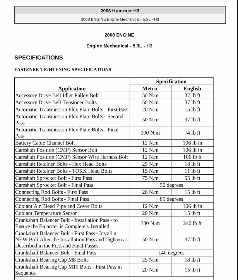
Crankshaft Bearing Cap M10 Bolts - Final Pass in Sequence
80 degrees
Crankshaft Bearing Cap M10 Studs - First Pass in Sequence
20 N.m 15 lb ft
Crankshaft Bearing Cap M10 Studs - Final Pass in Sequence
51 degrees
Crankshaft Oil Deflector Nuts 25 N.m 18 lb ftCrankshaft Position (CKP) Sensor Bolt 25 N.m 18 lb ftCrankshaft Rear Oil Seal Housing Bolts 30 N.m 22 lb ftCylinder Head M8 Bolts - in Sequence 30 N.m 22 lb ftCylinder Head M11 Bolts - First Pass in Sequence 30 N.m 22 lb ftCylinder Head M11 Bolts - Second Pass in Sequence
90 degrees
Cylinder Head M11 Bolts - Final Pass in Sequence 70 degreesCylinder Head Plug 20 N.m 15 lb ftEngine Block Coolant Drain Hole Plug 60 N.m 44 lb ftEngine Block Coolant Heater 50 N.m 37 lb ftEngine Block Oil Gallery Plugs 60 N.m 44 lb ftEngine Harness Ground Strap Bolt/Stud 16 N.m 12 lb ftEngine Harness-to-Generator Bracket Bolt 9 N.m 80 lb inEngine Harness Retainer-to-Intake Manifold Nut 5 N.m 44 lb inEngine Mount Bracket Through Bolt 100 N.m 74 lb ftEngine Mount-to-Engine Block Bolts 55 N.m 41 lb ftEvaporative (EVAP) Emission Pipe Bracket Nut 20 N.m 15 lb ftExhaust Manifold Bolts - First Pass 15 N.m 11 lb ftExhaust Manifold Bolts - Final Pass 20 N.m 15 lb ftExhaust Manifold Heat Shield Bolts 9 N.m 80 lb inExhaust Manifold Studs 20 N.m 15 lb ftFront Cover Bolts 25 N.m 18 lb ftFuel Injection Fuel Rail Bolts 10 N.m 89 lb inFuel Injection Fuel Rail Crossover Tube Bolts 3.8 N.m 34 lb inFuel Rail Stop Bracket Bolt 50 N.m 37 lb ftGenerator Bracket Bolts 50 N.m 37 lb ftIgnition Coil Bracket-to-Valve Rocker Arm Cover Studs
12 N.m 106 lb in
2008 Hummer H3
2008 ENGINE Engine Mechanical - 5.3L - H3
MY
Sunday, March 29, 2009 10:47:38 PM Page 2 © 2005 Mitchell Repair Information Company, LLC.

Ignition Coil-to-Bracket Bolts 10 N.m 89 lb inIntake Manifold Bolts - First Pass in Sequence 5 N.m 44 lb inIntake Manifold Bolts - Final Pass in Sequence 10 N.m 89 lb inIntake Manifold Sight Shield Retainer Bolts 5 N.m 44 lb inJ 41798 M8 Bolt 25 N.m 18 lb ftJ 41798 M10 Bolts 50 N.m 37 lb ftKnock Sensor Bolts 25 N.m 18 lb ftNegative Battery Cable Stud 25 N.m 18 lb ftOil Filter 30 N.m 22 lb ftOil Filter Fitting 55 N.m 40 lb ftOil Level Indicator Switch 20 N.m 15 lb ftOil Level Indicator Tube Bolt 25 N.m 18 lb ftOil Pan Baffle Bolts 9 N.m 80 lb inOil Pan Closeout Cover Bolt - Left Side 9 N.m 80 lb inOil Pan Closeout Cover Bolt - Right Side 9 N.m 80 lb inOil Pan Cover Bolts 9 N.m 80 lb inOil Pan Drain Plug 25 N.m 18 lb ftOil Pan M6 Bolts - Oil Pan-to-Rear Housing 12 N.m 106 lb inOil Pan M8 Bolts - Oil Pan-to-Engine Block and Oil Pan-to-Front Cover
25 N.m 18 lb ft
Oil Pressure Relief Valve 27 N.m 20 lb ftOil Pressure Sensor 35 N.m 26 lb ftOil Pump Cover Bolts 12 N.m 106 lb inOil Pump Relief Valve Plug 12 N.m 106 lb inOil Pump Screen Nuts 25 N.m 18 lb ftOil Pump Screen-to-Oil Pump Bolts 12 N.m 106 lb inOil Pump-to-Engine Block Bolts 25 N.m 18 lb ftPower Steering Pump-to-Engine Block Bolts 50 N.m 37 lb ftSpark Plugs 15 N.m 11 lb ftThrottle Body Bolts 10 N.m 89 lb inThrottle Body Nuts 10 N.m 89 lb inThrottle Body Studs 6 N.m 53 lb inTiming Chain Tensioner Bolts 25 N.m 18 lb ftValley Cover Bolts 25 N.m 18 lb ftValve Lifter Guide Bolts 12 N.m 106 lb in
2008 Hummer H3
2008 ENGINE Engine Mechanical - 5.3L - H3
MY
Sunday, March 29, 2009 10:47:38 PM Page 3 © 2005 Mitchell Repair Information Company, LLC.
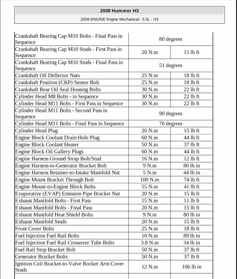
ENGINE MECHANICAL SPECIFICATIONS
Valve Rocker Arm Bolts 30 N.m 22 lb ftValve Rocker Arm Cover Bolts 12 N.m 106 lb inWater Inlet Housing Bolts 15 N.m 11 lb ftWater Pump Bolts - First Pass 15 N.m 11 lb ftWater Pump Bolts - Final Pass 30 N.m 22 lb ft
ApplicationSpecification
Metric EnglishGeneral
� Engine Type V8
� Displacement 5.3L 325 CID
� RPO LH8
� VIN L
� Bore 96.0-96.018 mm 3.779-3.78 in
� Stroke 92.0 mm 3.622 in
� Compression Ratio 9.95:1
� Firing Order 1-8-7-2-6-5-4-3
� Spark Plug Gap 1.02 mm 0.04 in
Block
� Camshaft Bearing Bore 1 and 5 Diameter 59.58-59.63 mm 2.345-2.347 in
� Camshaft Bearing Bore 2 and 4 Diameter 59.08-59.13 mm 2.325-2.327 in
� Camshaft Bearing Bore 3 Diameter 58.58-58.63 mm 2.306-2.308 in
� Crankshaft Main Bearing Bore Diameter 69.871-69.889
mm2.75-2.751 in
� Crankshaft Main Bearing Bore Out-of-Round 0.006 mm 0.0002 in
� Cylinder Bore Diameter 96.0-96.018 mm 3.779-3.78 in
� Cylinder Head Deck Height - Measuring from the Centerline of Crankshaft to the Deck Face
234.57-234.82 mm
9.235-9.245 in
� Cylinder Head Deck Surface Flatness - Measured Within a 152.4 mm (6.0 in) Area
0.11 mm 0.004 in
2008 Hummer H3
2008 ENGINE Engine Mechanical - 5.3L - H3
MY
Sunday, March 29, 2009 10:47:38 PM Page 4 © 2005 Mitchell Repair Information Company, LLC.
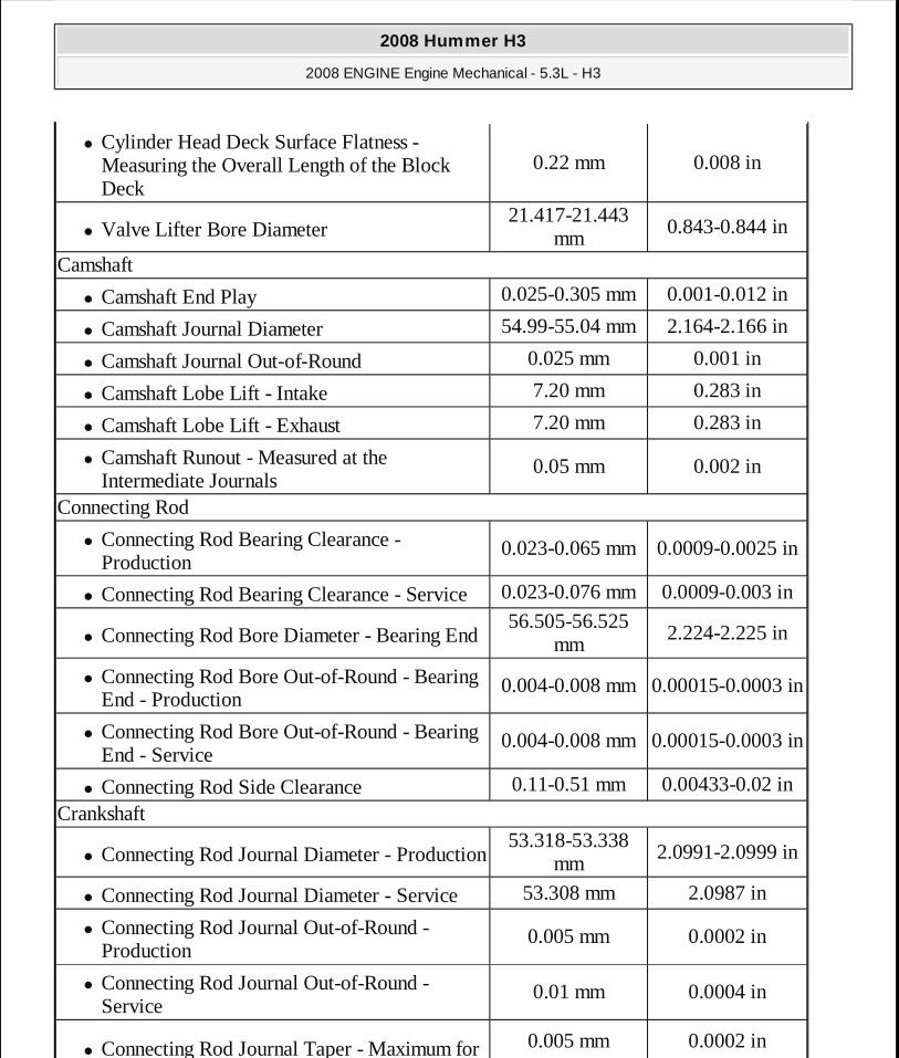
� Cylinder Head Deck Surface Flatness - Measuring the Overall Length of the Block Deck
0.22 mm 0.008 in
� Valve Lifter Bore Diameter 21.417-21.443
mm0.843-0.844 in
Camshaft
� Camshaft End Play 0.025-0.305 mm 0.001-0.012 in
� Camshaft Journal Diameter 54.99-55.04 mm 2.164-2.166 in
� Camshaft Journal Out-of-Round 0.025 mm 0.001 in
� Camshaft Lobe Lift - Intake 7.20 mm 0.283 in
� Camshaft Lobe Lift - Exhaust 7.20 mm 0.283 in
� Camshaft Runout - Measured at the Intermediate Journals
0.05 mm 0.002 in
Connecting Rod
� Connecting Rod Bearing Clearance - Production
0.023-0.065 mm 0.0009-0.0025 in
� Connecting Rod Bearing Clearance - Service 0.023-0.076 mm 0.0009-0.003 in
� Connecting Rod Bore Diameter - Bearing End 56.505-56.525
mm2.224-2.225 in
� Connecting Rod Bore Out-of-Round - Bearing End - Production
0.004-0.008 mm0.00015-0.0003 in
� Connecting Rod Bore Out-of-Round - Bearing End - Service
0.004-0.008 mm0.00015-0.0003 in
� Connecting Rod Side Clearance 0.11-0.51 mm 0.00433-0.02 in
Crankshaft
� Connecting Rod Journal Diameter - Production 53.318-53.338
mm2.0991-2.0999 in
� Connecting Rod Journal Diameter - Service 53.308 mm 2.0987 in
� Connecting Rod Journal Out-of-Round - Production
0.005 mm 0.0002 in
� Connecting Rod Journal Out-of-Round - Service
0.01 mm 0.0004 in
� Connecting Rod Journal Taper - Maximum for 0.005 mm 0.0002 in
2008 Hummer H3
2008 ENGINE Engine Mechanical - 5.3L - H3
MY
Sunday, March 29, 2009 10:47:38 PM Page 5 © 2005 Mitchell Repair Information Company, LLC.

1/2 of Journal Length - Production
� Connecting Rod Journal Taper - Maximum for 1/2 of Journal Length - Service
0.02 mm 0.00078 in
� Crankshaft End Play 0.04-0.2 mm 0.0015-0.0078 in
� Crankshaft Main Bearing Clearance - Production
0.02-0.052 mm 0.0008-0.0021 in
� Crankshaft Main Bearing Clearance - Service 0.02-0.065 mm 0.0008-0.0025 in
� Crankshaft Main Journal Diameter - Production
64.992-65.008 mm
2.558-2.559 in
� Crankshaft Main Journal Diameter - Service 64.992 mm 2.558 in
� Crankshaft Main Journal Out-of-Round - Production
0.003 mm 0.000118 in
� Crankshaft Main Journal Out-of-Round - Service
0.008 mm 0.0003 in
� Crankshaft Main Journal Taper - Production 0.01 mm 0.0004 in
� Crankshaft Main Journal Taper - Service 0.02 mm 0.00078 in
� Crankshaft Rear Flange Runout 0.05 mm 0.002 in
� Crankshaft Reluctor Ring Runout - Measured 1.0 mm (0.04 in) Below Tooth Diameter
0.7 mm 0.028 in
� Crankshaft Thrust Surface - Production 26.14-26.22 mm 1.029-1.0315 in
� Crankshaft Thrust Surface - Service 26.22 mm 1.0315 in
� Crankshaft Thrust Surface Runout 0.025 mm 0.001 in
Cylinder Head
� Cylinder Head Height/Thickness - Measured from the Cylinder Head Deck to the Valve Rocker Arm Cover Seal Surface
120.2 mm 4.732 in
� Surface Flatness - Block Deck - Measured Within a 152.4 mm (6.0 in) Area
0.08 mm 0.003 in
� Surface Flatness - Block Deck - Measuring the Overall Length of the Cylinder Head
0.1 mm 0.004 in
� Surface Flatness - Exhaust Manifold Deck 0.13 mm 0.005 in
� Surface Flatness - Intake Manifold Deck 0.08 mm 0.0031 in
2008 Hummer H3
2008 ENGINE Engine Mechanical - 5.3L - H3
MY
Sunday, March 29, 2009 10:47:38 PM Page 6 © 2005 Mitchell Repair Information Company, LLC.
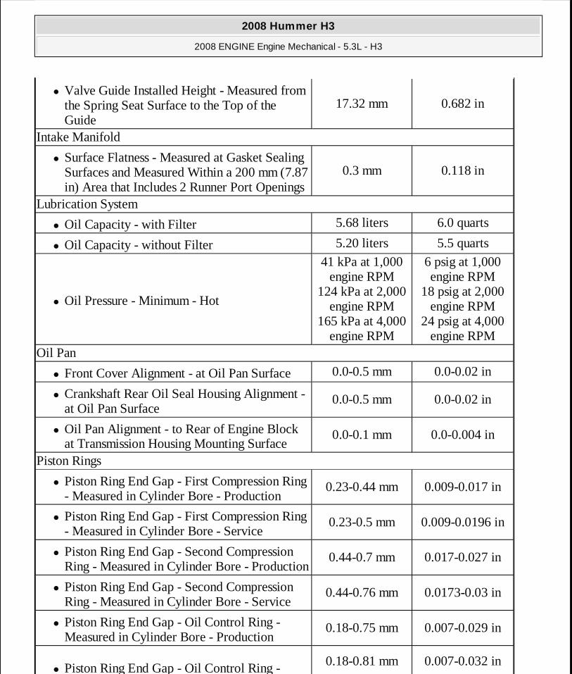
� Valve Guide Installed Height - Measured from the Spring Seat Surface to the Top of the Guide
17.32 mm 0.682 in
Intake Manifold
� Surface Flatness - Measured at Gasket Sealing Surfaces and Measured Within a 200 mm (7.87 in) Area that Includes 2 Runner Port Openings
0.3 mm 0.118 in
Lubrication System
� Oil Capacity - with Filter 5.68 liters 6.0 quarts
� Oil Capacity - without Filter 5.20 liters 5.5 quarts
� Oil Pressure - Minimum - Hot
41 kPa at 1,000 engine RPM
124 kPa at 2,000 engine RPM
165 kPa at 4,000 engine RPM
6 psig at 1,000 engine RPM
18 psig at 2,000 engine RPM
24 psig at 4,000 engine RPM
Oil Pan
� Front Cover Alignment - at Oil Pan Surface 0.0-0.5 mm 0.0-0.02 in
� Crankshaft Rear Oil Seal Housing Alignment - at Oil Pan Surface
0.0-0.5 mm 0.0-0.02 in
� Oil Pan Alignment - to Rear of Engine Block at Transmission Housing Mounting Surface
0.0-0.1 mm 0.0-0.004 in
Piston Rings
� Piston Ring End Gap - First Compression Ring - Measured in Cylinder Bore - Production
0.23-0.44 mm 0.009-0.017 in
� Piston Ring End Gap - First Compression Ring - Measured in Cylinder Bore - Service
0.23-0.5 mm 0.009-0.0196 in
� Piston Ring End Gap - Second Compression Ring - Measured in Cylinder Bore - Production
0.44-0.7 mm 0.017-0.027 in
� Piston Ring End Gap - Second Compression Ring - Measured in Cylinder Bore - Service
0.44-0.76 mm 0.0173-0.03 in
� Piston Ring End Gap - Oil Control Ring - Measured in Cylinder Bore - Production
0.18-0.75 mm 0.007-0.029 in
� Piston Ring End Gap - Oil Control Ring - 0.18-0.81 mm 0.007-0.032 in
2008 Hummer H3
2008 ENGINE Engine Mechanical - 5.3L - H3
MY
Sunday, March 29, 2009 10:47:38 PM Page 7 © 2005 Mitchell Repair Information Company, LLC.
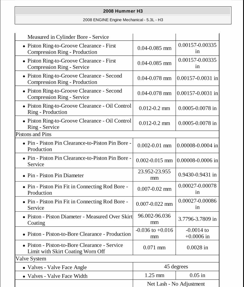
Measured in Cylinder Bore - Service
� Piston Ring-to-Groove Clearance - First Compression Ring - Production
0.04-0.085 mm 0.00157-0.00335 in
� Piston Ring-to-Groove Clearance - First Compression Ring - Service
0.04-0.085 mm0.00157-0.00335
in
� Piston Ring-to-Groove Clearance - Second Compression Ring - Production
0.04-0.078 mm 0.00157-0.0031 in
� Piston Ring-to-Groove Clearance - Second Compression Ring - Service
0.04-0.078 mm 0.00157-0.0031 in
� Piston Ring-to-Groove Clearance - Oil Control Ring - Production
0.012-0.2 mm 0.0005-0.0078 in
� Piston Ring-to-Groove Clearance - Oil Control Ring - Service
0.012-0.2 mm 0.0005-0.0078 in
Pistons and Pins
� Pin - Piston Pin Clearance-to-Piston Pin Bore - Production
0.002-0.01 mm 0.00008-0.0004 in
� Pin - Piston Pin Clearance-to-Piston Pin Bore - Service
0.002-0.015 mm0.00008-0.0006 in
� Pin - Piston Pin Diameter 23.952-23.955
mm0.9430-0.9431 in
� Pin - Piston Pin Fit in Connecting Rod Bore - Production
0.007-0.02 mm0.00027-0.00078
in
� Pin - Piston Pin Fit in Connecting Rod Bore - Service
0.007-0.022 mm0.00027-0.00086
in
� Piston - Piston Diameter - Measured Over Skirt Coating
96.002-96.036 mm
3.7796-3.7809 in
� Piston - Piston-to-Bore Clearance - Production -0.036 to +0.016
mm-0.0014 to +0.0006 in
� Piston - Piston-to-Bore Clearance - Service Limit with Skirt Coating Worn Off
0.071 mm 0.0028 in
Valve System
� Valves - Valve Face Angle 45 degrees
� Valves - Valve Face Width 1.25 mm 0.05 in
Net Lash - No Adjustment
2008 Hummer H3
2008 ENGINE Engine Mechanical - 5.3L - H3
MY
Sunday, March 29, 2009 10:47:38 PM Page 8 © 2005 Mitchell Repair Information Company, LLC.
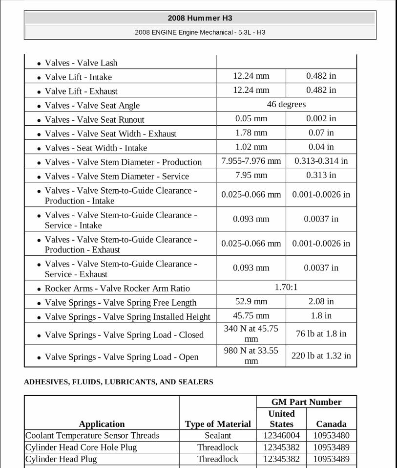
ADHESIVES, FLUIDS, LUBRICANTS, AND SEALERS
� Valves - Valve Lash
� Valve Lift - Intake 12.24 mm 0.482 in
� Valve Lift - Exhaust 12.24 mm 0.482 in
� Valves - Valve Seat Angle 46 degrees
� Valves - Valve Seat Runout 0.05 mm 0.002 in
� Valves - Valve Seat Width - Exhaust 1.78 mm 0.07 in
� Valves - Seat Width - Intake 1.02 mm 0.04 in
� Valves - Valve Stem Diameter - Production 7.955-7.976 mm 0.313-0.314 in
� Valves - Valve Stem Diameter - Service 7.95 mm 0.313 in
� Valves - Valve Stem-to-Guide Clearance - Production - Intake
0.025-0.066 mm 0.001-0.0026 in
� Valves - Valve Stem-to-Guide Clearance - Service - Intake
0.093 mm 0.0037 in
� Valves - Valve Stem-to-Guide Clearance - Production - Exhaust
0.025-0.066 mm 0.001-0.0026 in
� Valves - Valve Stem-to-Guide Clearance - Service - Exhaust
0.093 mm 0.0037 in
� Rocker Arms - Valve Rocker Arm Ratio 1.70:1
� Valve Springs - Valve Spring Free Length 52.9 mm 2.08 in
� Valve Springs - Valve Spring Installed Height 45.75 mm 1.8 in
� Valve Springs - Valve Spring Load - Closed 340 N at 45.75
mm76 lb at 1.8 in
� Valve Springs - Valve Spring Load - Open 980 N at 33.55
mm220 lb at 1.32 in
Application Type of Material
GM Part NumberUnited States Canada
Coolant Temperature Sensor Threads Sealant 12346004 10953480Cylinder Head Core Hole Plug Threadlock 12345382 10953489Cylinder Head Plug Threadlock 12345382 10953489
2008 Hummer H3
2008 ENGINE Engine Mechanical - 5.3L - H3
MY
Sunday, March 29, 2009 10:47:38 PM Page 9 © 2005 Mitchell Repair Information Company, LLC.
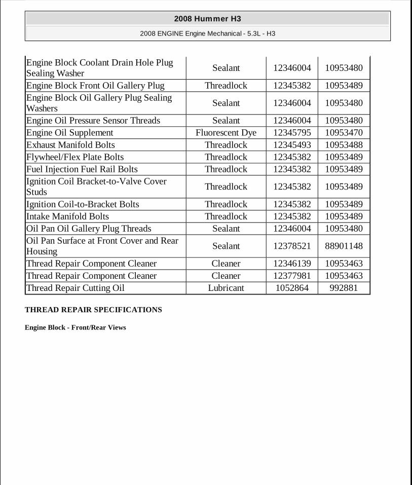
THREAD REPAIR SPECIFICATIONS
Engine Block - Front/Rear Views
Engine Block Coolant Drain Hole Plug Sealing Washer
Sealant 12346004 10953480
Engine Block Front Oil Gallery Plug Threadlock 12345382 10953489Engine Block Oil Gallery Plug Sealing Washers
Sealant 12346004 10953480
Engine Oil Pressure Sensor Threads Sealant 12346004 10953480Engine Oil Supplement Fluorescent Dye 12345795 10953470Exhaust Manifold Bolts Threadlock 12345493 10953488Flywheel/Flex Plate Bolts Threadlock 12345382 10953489Fuel Injection Fuel Rail Bolts Threadlock 12345382 10953489Ignition Coil Bracket-to-Valve Cover Studs
Threadlock 12345382 10953489
Ignition Coil-to-Bracket Bolts Threadlock 12345382 10953489Intake Manifold Bolts Threadlock 12345382 10953489Oil Pan Oil Gallery Plug Threads Sealant 12346004 10953480Oil Pan Surface at Front Cover and Rear Housing
Sealant 12378521 88901148
Thread Repair Component Cleaner Cleaner 12346139 10953463Thread Repair Component Cleaner Cleaner 12377981 10953463Thread Repair Cutting Oil Lubricant 1052864 992881
2008 Hummer H3
2008 ENGINE Engine Mechanical - 5.3L - H3
MY
Sunday, March 29, 2009 10:47:38 PM Page 10 © 2005 Mitchell Repair Information Company, LLC.
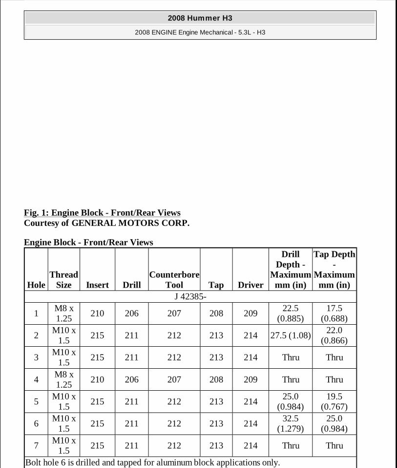
Fig. 1: Engine Block - Front/Rear Views Courtesy of GENERAL MOTORS CORP.
Engine Block - Front/Rear Views
HoleThread
Size Insert DrillCounterbore
Tool Tap Driver
Drill Depth -
Maximum mm (in)
Tap Depth -
Maximum mm (in)
J 42385-
1M8 x 1.25
210 206 207 208 20922.5
(0.885)17.5
(0.688)
2M10 x
1.5215 211 212 213 214 27.5 (1.08)
22.0 (0.866)
3M10 x
1.5215 211 212 213 214 Thru Thru
4M8 x 1.25
210 206 207 208 209 Thru Thru
5M10 x
1.5215 211 212 213 214
25.0 (0.984)
19.5 (0.767)
6M10 x
1.5215 211 212 213 214
32.5 (1.279)
25.0 (0.984)
7M10 x
1.5215 211 212 213 214 Thru Thru
Bolt hole 6 is drilled and tapped for aluminum block applications only.
2008 Hummer H3
2008 ENGINE Engine Mechanical - 5.3L - H3
MY
Sunday, March 29, 2009 10:47:38 PM Page 11 © 2005 Mitchell Repair Information Company, LLC.
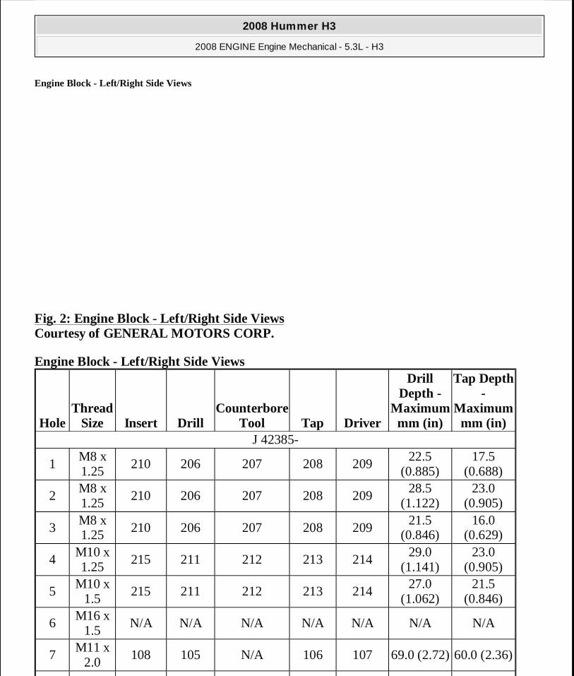
Engine Block - Left/Right Side Views
Fig. 2: Engine Block - Left/Right Side Views Courtesy of GENERAL MOTORS CORP.
Engine Block - Left/Right Side Views
HoleThread
Size Insert DrillCounterbore
Tool Tap Driver
Drill Depth -
Maximum mm (in)
Tap Depth -
Maximum mm (in)
J 42385-
1M8 x 1.25
210 206 207 208 20922.5
(0.885)17.5
(0.688)
2M8 x 1.25
210 206 207 208 20928.5
(1.122)23.0
(0.905)
3M8 x 1.25 210 206 207 208 209
21.5 (0.846)
16.0 (0.629)
4M10 x 1.25
215 211 212 213 21429.0
(1.141)23.0
(0.905)
5M10 x
1.5215 211 212 213 214
27.0 (1.062)
21.5 (0.846)
6M16 x
1.5N/A N/A N/A N/A N/A N/A N/A
7M11 x
2.0108 105 N/A 106 107 69.0 (2.72)60.0 (2.36)
2008 Hummer H3
2008 ENGINE Engine Mechanical - 5.3L - H3
MY
Sunday, March 29, 2009 10:47:38 PM Page 12 © 2005 Mitchell Repair Information Company, LLC.
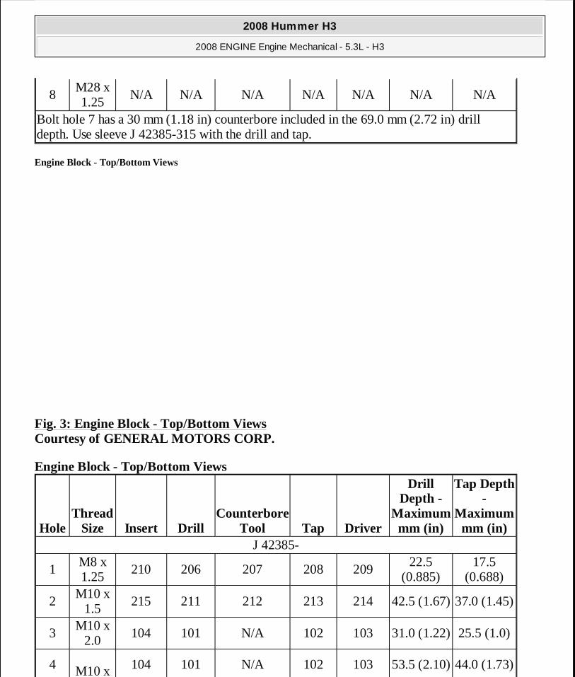
Engine Block - Top/Bottom Views
Fig. 3: Engine Block - Top/Bottom Views Courtesy of GENERAL MOTORS CORP.
Engine Block - Top/Bottom Views
8M28 x 1.25
N/A N/A N/A N/A N/A N/A N/A
Bolt hole 7 has a 30 mm (1.18 in) counterbore included in the 69.0 mm (2.72 in) drill depth. Use sleeve J 42385-315 with the drill and tap.
HoleThread
Size Insert DrillCounterbore
Tool Tap Driver
Drill Depth -
Maximum mm (in)
Tap Depth -
Maximum mm (in)
J 42385-
1M8 x 1.25
210 206 207 208 20922.5
(0.885)17.5
(0.688)
2M10 x
1.5215 211 212 213 214 42.5 (1.67)37.0 (1.45)
3M10 x
2.0104 101 N/A 102 103 31.0 (1.22) 25.5 (1.0)
4 M10 x 104 101 N/A 102 103 53.5 (2.10)44.0 (1.73)
2008 Hummer H3
2008 ENGINE Engine Mechanical - 5.3L - H3
MY
Sunday, March 29, 2009 10:47:38 PM Page 13 © 2005 Mitchell Repair Information Company, LLC.

Cylinder Head - Top/End Views
Fig. 4: Cylinder Head - Top/End Views Courtesy of GENERAL MOTORS CORP.
Cylinder Head - Top/End Views
2.0
5M8 x 1.25
210 206 207 208 20926.5
(1.043)19.0
(0.748)
� Bolt hole 2 has an 11.5 mm (0.452 in) counterbore included in the 42.5 mm (1.67 in) drill depth. Use sleeve J 42385-311 with the drill and tap.
� Bolt hole 3 has a 1.5 mm (0.059 in) counterbore included in the 31.0 mm (1.22 in) drill depth. Use sleeve J 42385-316 with the drill and tap.
� Bolt hole 4 has a 20.5 mm (0.807 in) counterbore included in the 53.5 mm (2.10 in) drill depth.
HoleThread
Size Insert DrillCounterbore
Tool Tap Driver
Drill Depth -
Maximum mm (in)
Tap Depth -
Maximum mm (in)
J 42385-
1M8 x 1.25
210 206 207 208 209 26.5 (1.04)19.0
(0.784)
2M6 x 1.0
205 201 202 203 20420.05
(0.789)16.05
(0.632)
3 M10 x 215 211 212 213 214 28.0 (1.10) 20.0
2008 Hummer H3
2008 ENGINE Engine Mechanical - 5.3L - H3
MY
Sunday, March 29, 2009 10:47:38 PM Page 14 © 2005 Mitchell Repair Information Company, LLC.
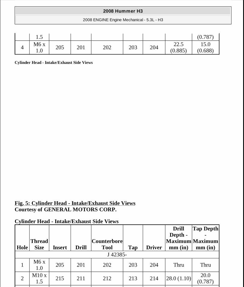
Cylinder Head - Intake/Exhaust Side Views
Fig. 5: Cylinder Head - Intake/Exhaust Side Views Courtesy of GENERAL MOTORS CORP.
Cylinder Head - Intake/Exhaust Side Views
1.5 (0.787)
4M6 x 1.0
205 201 202 203 20422.5
(0.885)15.0
(0.688)
HoleThread
Size Insert DrillCounterbore
Tool Tap Driver
Drill Depth -
Maximum mm (in)
Tap Depth -
Maximum mm (in)
J 42385-
1M6 x 1.0
205 201 202 203 204 Thru Thru
2M10 x
1.5215 211 212 213 214 28.0 (1.10)
20.0 (0.787)
2008 Hummer H3
2008 ENGINE Engine Mechanical - 5.3L - H3
MY
Sunday, March 29, 2009 10:47:38 PM Page 15 © 2005 Mitchell Repair Information Company, LLC.
COMPONENT LOCATOR
DISASSEMBLED VIEWS
3M8 x 1.25
210 206 207 208 20921.0
(0.826)16.0
(0.629)
4M14 x 1.25
N/A N/A N/A N/A N/A N/A N/A
5M12 x
1.5N/A N/A N/A N/A N/A N/A N/A
2008 Hummer H3
2008 ENGINE Engine Mechanical - 5.3L - H3
MY
Sunday, March 29, 2009 10:47:38 PM Page 16 © 2005 Mitchell Repair Information Company, LLC.
Fig. 6: Intake Manifold/Upper Engine Courtesy of GENERAL MOTORS CORP.
2008 Hummer H3
2008 ENGINE Engine Mechanical - 5.3L - H3
MY
Sunday, March 29, 2009 10:47:38 PM Page 17 © 2005 Mitchell Repair Information Company, LLC.

Callout Component Name100 Engine Block307 Engine Coolant Air Bleed Pipe308 Engine Coolant Air Bleed Pipe O-Ring Seal308 Engine Coolant Air Bleed Pipe O-Ring Seal309 Bolt312 Bolt313 Engine Coolant Air Bleed Pipe Hole Cover500 Intake Manifold506 Valve Lifter Oil Manifold Bolt507 Throttle Body Nut508 Throttle Body509 Throttle Body Seal510 Sequential Multi-Port Fuel Injector Assembly with Fuel Rail511 Fuel Injection Fuel Rail Bracket Bolt512 Intake Manifold Bolt513 Intake Manifold Seal514 Intake Manifold Gasket537 O-Ring Seal538 Throttle Body Bolt555 Engine Valley Cover556 Gasket557 Fuel Injection Fuel Rail Bracket706 Engine Oil Pressure Sensor712 Fuel Injection Fuel Rail Stop713 Bolt714 Manifold Absolute Pressure (MAP) Sensor715 MAP Sensor O-Ring Seal729 Evaporative (EVAP) Emission Canister Purge Tube730 EVAP Emission Canister Purge Solenoid Valve731 EVAP Emission Canister Port Cap734 EVAP Emission Service Valve735 EVAP Emission Canister Purge Tube
2008 Hummer H3
2008 ENGINE Engine Mechanical - 5.3L - H3
MY
Sunday, March 29, 2009 10:47:38 PM Page 18 © 2005 Mitchell Repair Information Company, LLC.
Fig. 7: Cylinder Head/Upper Engine Courtesy of GENERAL MOTORS CORP.
Callout Component Name100 Engine Block209 Valve Lifter210 Valve Lifter Guide211 Valve Lifter Guide Bolt212 Valve Push Rod213 Valve Rocker Arm214 Valve Rocker Arm Pivot Support Bolt215 Valve Rocker Arm Pivot Support216 Cylinder Head Core Hole Plug
2008 Hummer H3
2008 ENGINE Engine Mechanical - 5.3L - H3
MY
Sunday, March 29, 2009 10:47:38 PM Page 19 © 2005 Mitchell Repair Information Company, LLC.
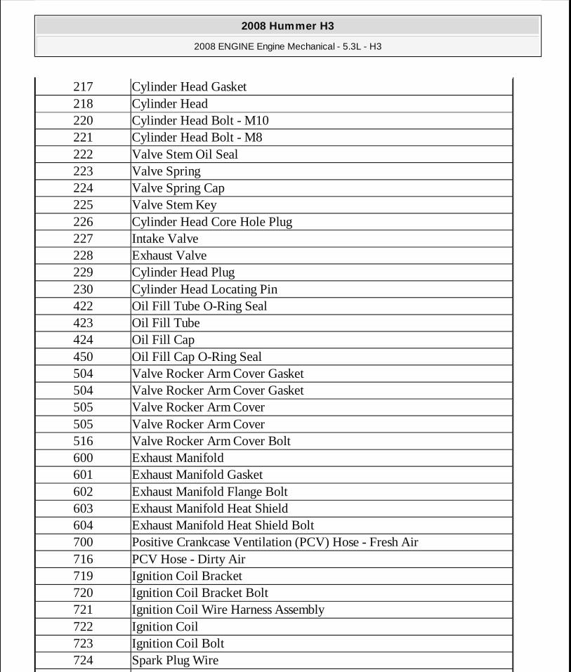
217 Cylinder Head Gasket218 Cylinder Head220 Cylinder Head Bolt - M10221 Cylinder Head Bolt - M8222 Valve Stem Oil Seal223 Valve Spring224 Valve Spring Cap225 Valve Stem Key226 Cylinder Head Core Hole Plug227 Intake Valve228 Exhaust Valve229 Cylinder Head Plug230 Cylinder Head Locating Pin422 Oil Fill Tube O-Ring Seal423 Oil Fill Tube424 Oil Fill Cap450 Oil Fill Cap O-Ring Seal504 Valve Rocker Arm Cover Gasket504 Valve Rocker Arm Cover Gasket505 Valve Rocker Arm Cover505 Valve Rocker Arm Cover516 Valve Rocker Arm Cover Bolt600 Exhaust Manifold601 Exhaust Manifold Gasket602 Exhaust Manifold Flange Bolt603 Exhaust Manifold Heat Shield604 Exhaust Manifold Heat Shield Bolt700 Positive Crankcase Ventilation (PCV) Hose - Fresh Air716 PCV Hose - Dirty Air719 Ignition Coil Bracket720 Ignition Coil Bracket Bolt721 Ignition Coil Wire Harness Assembly722 Ignition Coil723 Ignition Coil Bolt724 Spark Plug Wire
725
2008 Hummer H3
2008 ENGINE Engine Mechanical - 5.3L - H3
MY
Sunday, March 29, 2009 10:47:38 PM Page 20 © 2005 Mitchell Repair Information Company, LLC.

Fig. 8: Front of Engine Courtesy of GENERAL MOTORS CORP.
Engine Coolant Temperature Sensor726 Spark Plug
Callout Component Name100 Engine Block138 Crankshaft Balancer139 Crankshaft Balancer Bolt140 Crankshaft Front Oil Seal200 Camshaft
2008 Hummer H3
2008 ENGINE Engine Mechanical - 5.3L - H3
MY
Sunday, March 29, 2009 10:47:38 PM Page 21 © 2005 Mitchell Repair Information Company, LLC.
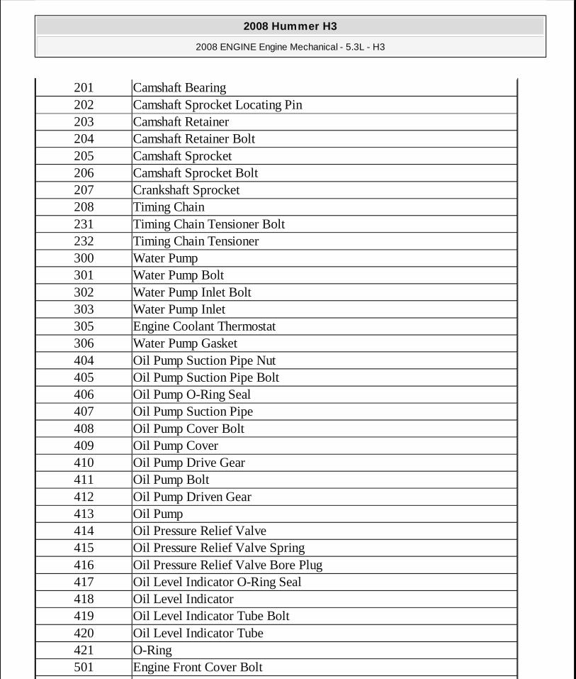
201 Camshaft Bearing202 Camshaft Sprocket Locating Pin203 Camshaft Retainer204 Camshaft Retainer Bolt205 Camshaft Sprocket206 Camshaft Sprocket Bolt207 Crankshaft Sprocket208 Timing Chain231 Timing Chain Tensioner Bolt232 Timing Chain Tensioner300 Water Pump301 Water Pump Bolt302 Water Pump Inlet Bolt303 Water Pump Inlet305 Engine Coolant Thermostat306 Water Pump Gasket404 Oil Pump Suction Pipe Nut405 Oil Pump Suction Pipe Bolt406 Oil Pump O-Ring Seal407 Oil Pump Suction Pipe408 Oil Pump Cover Bolt409 Oil Pump Cover410 Oil Pump Drive Gear411 Oil Pump Bolt412 Oil Pump Driven Gear413 Oil Pump414 Oil Pressure Relief Valve415 Oil Pressure Relief Valve Spring416 Oil Pressure Relief Valve Bore Plug417 Oil Level Indicator O-Ring Seal418 Oil Level Indicator419 Oil Level Indicator Tube Bolt420 Oil Level Indicator Tube421 O-Ring501 Engine Front Cover Bolt
502
2008 Hummer H3
2008 ENGINE Engine Mechanical - 5.3L - H3
MY
Sunday, March 29, 2009 10:47:38 PM Page 22 © 2005 Mitchell Repair Information Company, LLC.

Fig. 9: Rear of Engine Courtesy of GENERAL MOTORS CORP.
Engine Front Cover503 Engine Front Cover Gasket703 Camshaft Position (CMP) Sensor704 CMP Sensor O-Ring Seal705 CMP Sensor Bolt737 CMP Sensor Wire Harness Assembly738 CMP Sensor Wire Harness Assembly Bolt
Callout Component Name100 Engine Block132 Flex Plate - Automatic Transmission133 Flywheel Bolt141 Crankshaft Rear Oil Seal517 Crankshaft Rear Oil Seal Housing Bolt518 Crankshaft Rear Oil Seal Housing519 Crankshaft Rear Oil Seal Housing Gasket
2008 Hummer H3
2008 ENGINE Engine Mechanical - 5.3L - H3
MY
Sunday, March 29, 2009 10:47:38 PM Page 23 © 2005 Mitchell Repair Information Company, LLC.
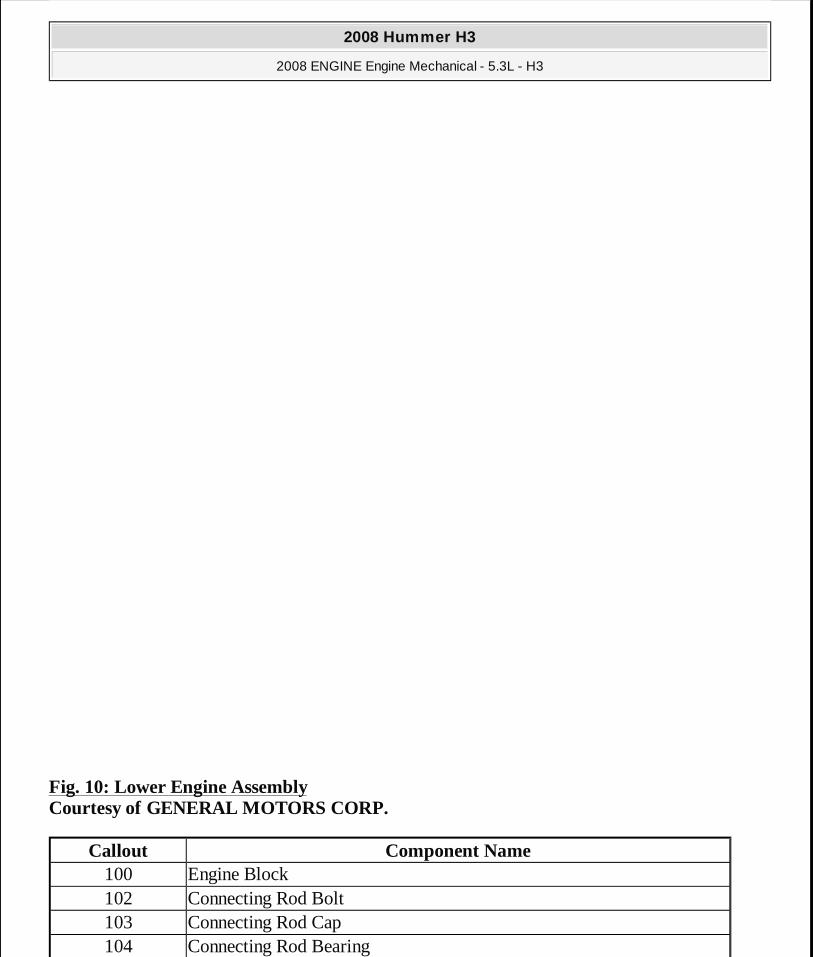
Fig. 10: Lower Engine Assembly Courtesy of GENERAL MOTORS CORP.
Callout Component Name100 Engine Block102 Connecting Rod Bolt103 Connecting Rod Cap104 Connecting Rod Bearing
2008 Hummer H3
2008 ENGINE Engine Mechanical - 5.3L - H3
MY
Sunday, March 29, 2009 10:47:38 PM Page 24 © 2005 Mitchell Repair Information Company, LLC.
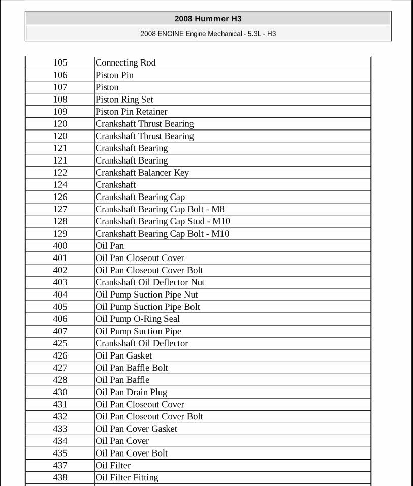
105 Connecting Rod106 Piston Pin107 Piston108 Piston Ring Set109 Piston Pin Retainer120 Crankshaft Thrust Bearing120 Crankshaft Thrust Bearing121 Crankshaft Bearing121 Crankshaft Bearing122 Crankshaft Balancer Key124 Crankshaft126 Crankshaft Bearing Cap127 Crankshaft Bearing Cap Bolt - M8128 Crankshaft Bearing Cap Stud - M10129 Crankshaft Bearing Cap Bolt - M10400 Oil Pan401 Oil Pan Closeout Cover402 Oil Pan Closeout Cover Bolt403 Crankshaft Oil Deflector Nut404 Oil Pump Suction Pipe Nut405 Oil Pump Suction Pipe Bolt406 Oil Pump O-Ring Seal407 Oil Pump Suction Pipe425 Crankshaft Oil Deflector426 Oil Pan Gasket427 Oil Pan Baffle Bolt428 Oil Pan Baffle430 Oil Pan Drain Plug431 Oil Pan Closeout Cover432 Oil Pan Closeout Cover Bolt433 Oil Pan Cover Gasket434 Oil Pan Cover435 Oil Pan Cover Bolt437 Oil Filter438 Oil Filter Fitting
439
2008 Hummer H3
2008 ENGINE Engine Mechanical - 5.3L - H3
MY
Sunday, March 29, 2009 10:47:38 PM Page 25 © 2005 Mitchell Repair Information Company, LLC.
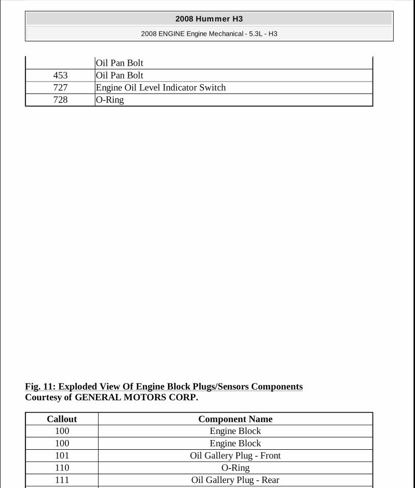
Fig. 11: Exploded View Of Engine Block Plugs/Sensors Components Courtesy of GENERAL MOTORS CORP.
Oil Pan Bolt453 Oil Pan Bolt727 Engine Oil Level Indicator Switch728 O-Ring
Callout Component Name100 Engine Block100 Engine Block101 Oil Gallery Plug - Front110 O-Ring111 Oil Gallery Plug - Rear
2008 Hummer H3
2008 ENGINE Engine Mechanical - 5.3L - H3
MY
Sunday, March 29, 2009 10:47:38 PM Page 26 © 2005 Mitchell Repair Information Company, LLC.
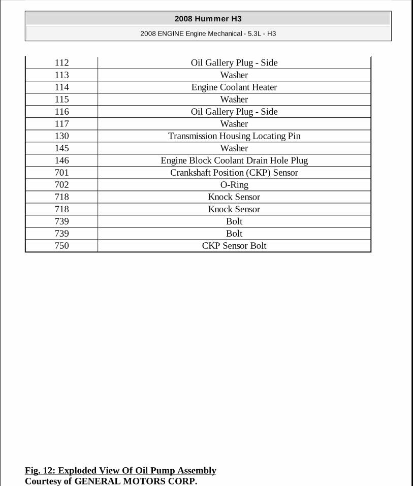
Fig. 12: Exploded View Of Oil Pump Assembly Courtesy of GENERAL MOTORS CORP.
112 Oil Gallery Plug - Side113 Washer114 Engine Coolant Heater115 Washer116 Oil Gallery Plug - Side117 Washer130 Transmission Housing Locating Pin145 Washer146 Engine Block Coolant Drain Hole Plug701 Crankshaft Position (CKP) Sensor702 O-Ring718 Knock Sensor718 Knock Sensor739 Bolt739 Bolt750 CKP Sensor Bolt
2008 Hummer H3
2008 ENGINE Engine Mechanical - 5.3L - H3
MY
Sunday, March 29, 2009 10:47:39 PM Page 27 © 2005 Mitchell Repair Information Company, LLC.
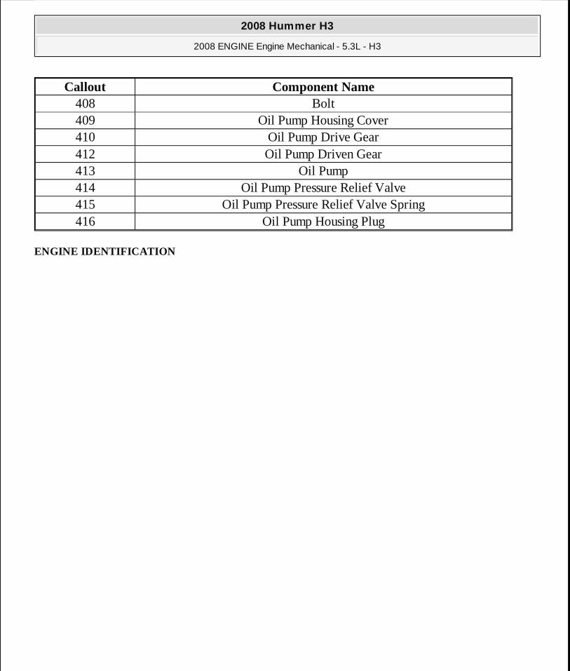
ENGINE IDENTIFICATION
Callout Component Name408 Bolt409 Oil Pump Housing Cover410 Oil Pump Drive Gear412 Oil Pump Driven Gear413 Oil Pump414 Oil Pump Pressure Relief Valve415 Oil Pump Pressure Relief Valve Spring416 Oil Pump Housing Plug
2008 Hummer H3
2008 ENGINE Engine Mechanical - 5.3L - H3
MY
Sunday, March 29, 2009 10:47:39 PM Page 28 © 2005 Mitchell Repair Information Company, LLC.
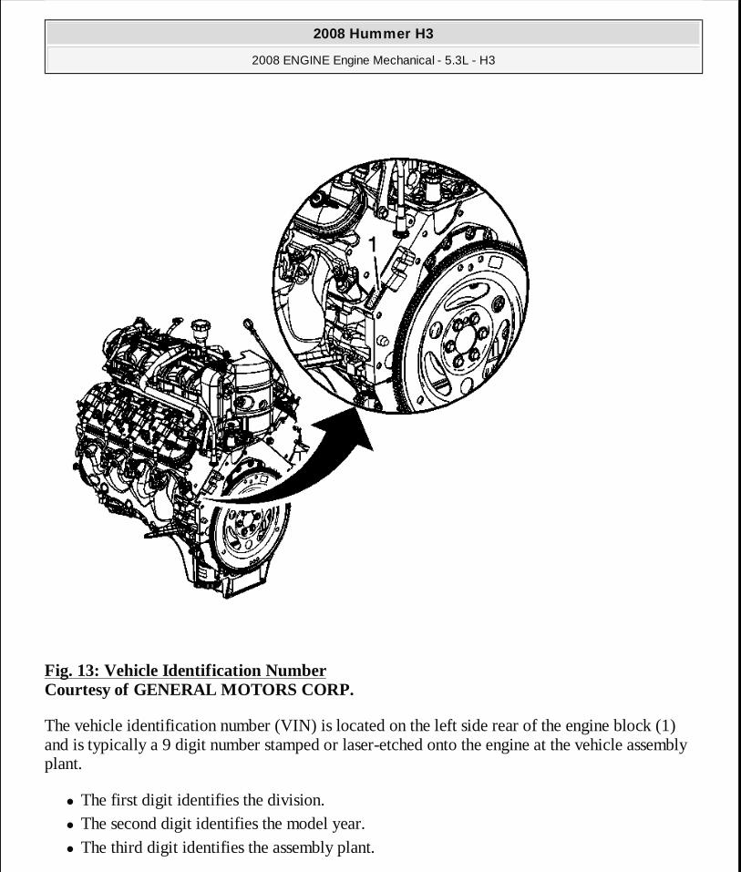
Fig. 13: Vehicle Identification Number Courtesy of GENERAL MOTORS CORP.
The vehicle identification number (VIN) is located on the left side rear of the engine block (1) and is typically a 9 digit number stamped or laser-etched onto the engine at the vehicle assembly plant.
� The first digit identifies the division. � The second digit identifies the model year. � The third digit identifies the assembly plant.
2008 Hummer H3
2008 ENGINE Engine Mechanical - 5.3L - H3
MY
Sunday, March 29, 2009 10:47:39 PM Page 29 © 2005 Mitchell Repair Information Company, LLC.
� The fourth through ninth digits are the last 6 digits of the VIN.
DIAGNOSTIC INFORMATION AND PROCEDURES
DIAGNOSTIC STARTING POINT - ENGINE MECHANICAL
Begin the system diagnosis by reviewing the Disassembled Views, Engine Component Description, and Lubrication Description. Reviewing the description and operation information helps you determine the correct symptom diagnostic procedure when a malfunction exists. Reviewing the description and operation information also helps you determine if the condition described by the customer is normal operation. Refer to Symptoms - Engine Mechanical in order to identify the correct procedure for diagnosing the system and where the procedure is located.
SYMPTOMS - ENGINE MECHANICAL
Strategy Based Diagnostics
1. Perform the Diagnostic System Check - Vehicle before using the symptom tables. 2. Review the system operations in order to familiarize yourself with the system functions.
Refer to Disassembled Views, Engine Component Description, and Lubrication Description.
All diagnosis on a vehicle should follow a logical process. Strategy based diagnostics is a uniform approach for repairing all systems. The diagnostic flow may always be used in order to resolve a system condition. The diagnostic flow is the place to start when repairs are necessary. For a detailed explanation, refer to Strategy Based Diagnosis .
Visual/Physical Inspection
� Inspect for aftermarket devices which could affect the operation of the engine. Refer to Checking Aftermarket Accessories .
� Inspect the easily accessible or visible system components for obvious damage or conditions which could cause the symptom.
� Inspect for the correct oil level, proper oil viscosity, and correct filter application. � Verify the exact operating conditions under which the concern exists. Note factors such as
engine RPM, ambient temperature, engine temperature, amount of engine warm-up time, and other specifics.
� Compare the engine sounds, if applicable, to a known good engine and make sure you are not trying to correct a normal condition.
2008 Hummer H3
2008 ENGINE Engine Mechanical - 5.3L - H3
MY
Sunday, March 29, 2009 10:47:39 PM Page 30 © 2005 Mitchell Repair Information Company, LLC.
Intermittent
Test the vehicle under the same conditions that the customer reported in order to verify the system is operating properly.
Symptom List
Refer to a symptom diagnostic procedure from the following list in order to diagnose the symptom:
� Base Engine Misfire without Internal Engine Noises � Base Engine Misfire with Abnormal Internal Lower Engine Noises � Base Engine Misfire with Abnormal Valve Train Noise
� Base Engine Misfire with Coolant Consumption
� Base Engine Misfire with Excessive Oil Consumption
� Engine Noise on Start-Up, but Only Lasting a Few Seconds � Upper Engine Noise, Regardless of Engine Speed
� Lower Engine Noise, Regardless of Engine Speed
� Engine Noise Under Load
� Engine Will Not Crank - Crankshaft Will Not Rotate
� Coolant in Combustion Chamber
� Coolant in Engine Oil � Engine Compression Test � Cylinder Leakage Test � Oil Consumption Diagnosis � Oil Pressure Diagnosis and Testing
� Oil Leak Diagnosis � Crankcase Ventilation System Inspection/Diagnosis � Drive Belt Chirping, Squeal, and Whine Diagnosis � Drive Belt Rumbling and Vibration Diagnosis � Drive Belt Falls Off and Excessive Wear Diagnosis � Drive Belt Tensioner Diagnosis
BASE ENGINE MISFIRE WITHOUT INTERNAL ENGINE NOISES
2008 Hummer H3
2008 ENGINE Engine Mechanical - 5.3L - H3
MY
Sunday, March 29, 2009 10:47:39 PM Page 31 © 2005 Mitchell Repair Information Company, LLC.
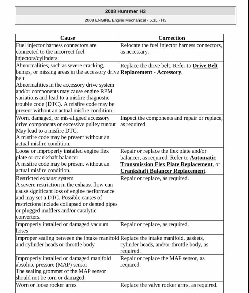
Cause CorrectionFuel injector harness connectors are connected to the incorrect fuel injectors/cylinders
Relocate the fuel injector harness connectors, as necessary.
Abnormalities, such as severe cracking, bumps, or missing areas in the accessory drive belt Abnormalities in the accessory drive system and/or components may cause engine RPM variations and lead to a misfire diagnostic trouble code (DTC). A misfire code may be present without an actual misfire condition.
Replace the drive belt. Refer to Drive Belt Replacement - Accessory.
Worn, damaged, or mis-aligned accessory drive components or excessive pulley runout May lead to a misfire DTC. A misfire code may be present without an actual misfire condition.
Inspect the components and repair or replace, as required.
Loose or improperly installed engine flex plate or crankshaft balancer A misfire code may be present without an actual misfire condition.
Repair or replace the flex plate and/or balancer, as required. Refer to Automatic Transmission Flex Plate Replacement, or Crankshaft Balancer Replacement.
Restricted exhaust system A severe restriction in the exhaust flow can cause significant loss of engine performance and may set a DTC. Possible causes of restrictions include collapsed or dented pipes or plugged mufflers and/or catalytic converters.
Repair or replace, as required.
Improperly installed or damaged vacuum hoses
Repair or replace, as required.
Improper sealing between the intake manifold and cylinder heads or throttle body
Replace the intake manifold, gaskets, cylinder heads, and/or throttle body, as required.
Improperly installed or damaged manifold absolute pressure (MAP) sensor The sealing grommet of the MAP sensor should not be torn or damaged.
Repair or replace the MAP sensor, as required.
Worn or loose rocker arms Replace the valve rocker arms, as required.
2008 Hummer H3
2008 ENGINE Engine Mechanical - 5.3L - H3
MY
Sunday, March 29, 2009 10:47:39 PM Page 32 © 2005 Mitchell Repair Information Company, LLC.
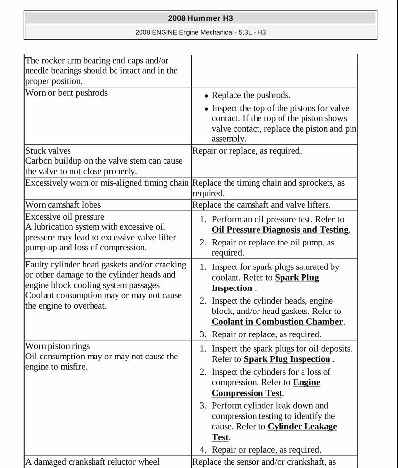
The rocker arm bearing end caps and/or needle bearings should be intact and in the proper position.Worn or bent pushrods
� Replace the pushrods. � Inspect the top of the pistons for valve
contact. If the top of the piston shows valve contact, replace the piston and pin assembly.
Stuck valves Carbon buildup on the valve stem can cause the valve to not close properly.
Repair or replace, as required.
Excessively worn or mis-aligned timing chainReplace the timing chain and sprockets, as required.
Worn camshaft lobes Replace the camshaft and valve lifters.Excessive oil pressure A lubrication system with excessive oil pressure may lead to excessive valve lifter pump-up and loss of compression.
1. Perform an oil pressure test. Refer to Oil Pressure Diagnosis and Testing.
2. Repair or replace the oil pump, as required.
Faulty cylinder head gaskets and/or cracking or other damage to the cylinder heads and engine block cooling system passages Coolant consumption may or may not cause the engine to overheat.
1. Inspect for spark plugs saturated by coolant. Refer to Spark Plug Inspection .
2. Inspect the cylinder heads, engine block, and/or head gaskets. Refer to Coolant in Combustion Chamber.
3. Repair or replace, as required. Worn piston rings Oil consumption may or may not cause the engine to misfire.
1. Inspect the spark plugs for oil deposits. Refer to Spark Plug Inspection .
2. Inspect the cylinders for a loss of compression. Refer to Engine Compression Test.
3. Perform cylinder leak down and compression testing to identify the cause. Refer to Cylinder Leakage Test.
4. Repair or replace, as required. A damaged crankshaft reluctor wheel Replace the sensor and/or crankshaft, as
2008 Hummer H3
2008 ENGINE Engine Mechanical - 5.3L - H3
MY
Sunday, March 29, 2009 10:47:39 PM Page 33 © 2005 Mitchell Repair Information Company, LLC.
BASE ENGINE MISFIRE WITH ABNORMAL INTERNAL LOWER ENGINE NOISES
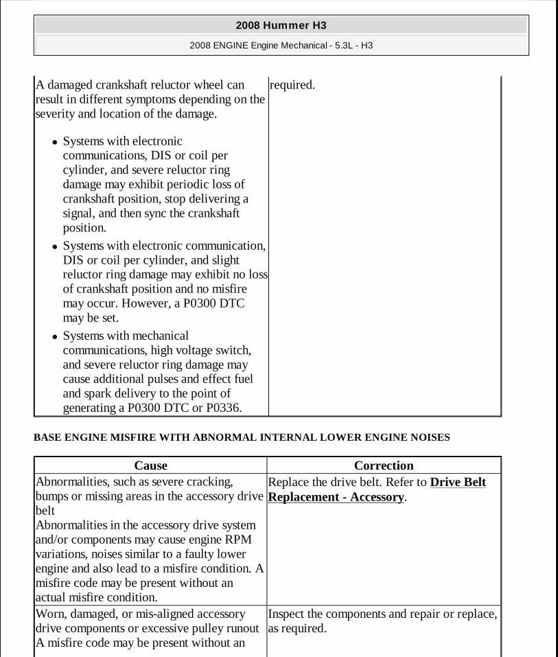
A damaged crankshaft reluctor wheel can result in different symptoms depending on the severity and location of the damage.
� Systems with electronic communications, DIS or coil per cylinder, and severe reluctor ring damage may exhibit periodic loss of crankshaft position, stop delivering a signal, and then sync the crankshaft position.
� Systems with electronic communication, DIS or coil per cylinder, and slight reluctor ring damage may exhibit no loss of crankshaft position and no misfire may occur. However, a P0300 DTC may be set.
� Systems with mechanical communications, high voltage switch, and severe reluctor ring damage may cause additional pulses and effect fuel and spark delivery to the point of generating a P0300 DTC or P0336.
required.
Cause CorrectionAbnormalities, such as severe cracking, bumps or missing areas in the accessory drive belt Abnormalities in the accessory drive system and/or components may cause engine RPM variations, noises similar to a faulty lower engine and also lead to a misfire condition. A misfire code may be present without an actual misfire condition.
Replace the drive belt. Refer to Drive Belt Replacement - Accessory.
Worn, damaged, or mis-aligned accessory drive components or excessive pulley runout A misfire code may be present without an
Inspect the components and repair or replace, as required.
2008 Hummer H3
2008 ENGINE Engine Mechanical - 5.3L - H3
MY
Sunday, March 29, 2009 10:47:39 PM Page 34 © 2005 Mitchell Repair Information Company, LLC.
BASE ENGINE MISFIRE WITH ABNORMAL VALVE TRAIN NOISE
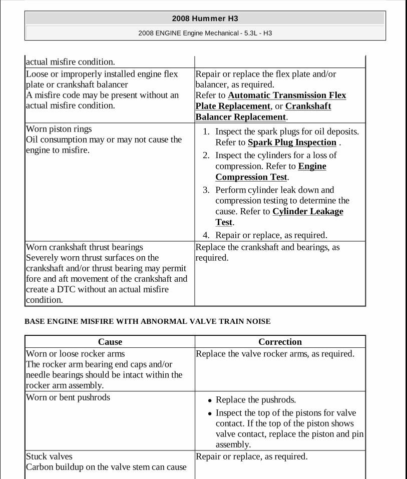
actual misfire condition.Loose or improperly installed engine flex plate or crankshaft balancer A misfire code may be present without an actual misfire condition.
Repair or replace the flex plate and/or balancer, as required. Refer to Automatic Transmission Flex Plate Replacement, or Crankshaft Balancer Replacement.
Worn piston rings Oil consumption may or may not cause the engine to misfire.
1. Inspect the spark plugs for oil deposits. Refer to Spark Plug Inspection .
2. Inspect the cylinders for a loss of compression. Refer to Engine Compression Test.
3. Perform cylinder leak down and compression testing to determine the cause. Refer to Cylinder Leakage Test.
4. Repair or replace, as required. Worn crankshaft thrust bearings Severely worn thrust surfaces on the crankshaft and/or thrust bearing may permit fore and aft movement of the crankshaft and create a DTC without an actual misfire condition.
Replace the crankshaft and bearings, as required.
Cause CorrectionWorn or loose rocker arms The rocker arm bearing end caps and/or needle bearings should be intact within the rocker arm assembly.
Replace the valve rocker arms, as required.
Worn or bent pushrods� Replace the pushrods. � Inspect the top of the pistons for valve
contact. If the top of the piston shows valve contact, replace the piston and pin assembly.
Stuck valves Carbon buildup on the valve stem can cause
Repair or replace, as required.
2008 Hummer H3
2008 ENGINE Engine Mechanical - 5.3L - H3
MY
Sunday, March 29, 2009 10:47:39 PM Page 35 © 2005 Mitchell Repair Information Company, LLC.

BASE ENGINE MISFIRE WITH COOLANT CONSUMPTION
BASE ENGINE MISFIRE WITH EXCESSIVE OIL CONSUMPTION
the valve to not close properly.Excessively worn or mis-aligned timing chainReplace the timing chain and sprockets, as
required.Worn camshaft lobes Replace the camshaft and valve lifters.Sticking lifters Replace, as required.Cut or damaged oil pump screen O-ring seal which may cause aeration of the engine oil
Repair, as required. Refer to Oil Pressure Diagnosis and Testing.
Cause CorrectionFaulty cylinder head gaskets and/or cracking or other damage to the cylinder heads and engine block cooling system passages Coolant consumption may or may not cause the engine to overheat.
1. Inspect for spark plugs saturated by coolant. Refer to Spark Plug Inspection .
2. Perform a cylinder leak down test. Refer to Cylinder Leakage Test.
3. Inspect the cylinder heads and engine block for damage to the coolant passages and/or a faulty head gasket. Refer to Coolant in Combustion Chamber.
4. Repair or replace, as required.
Cause CorrectionWorn valves, valve guides and/or valve stem oil seals
1. Inspect the spark plugs for oil deposits. Refer to Spark Plug Inspection .
2. Repair or replace, as required. Worn piston rings Oil consumption may or may not cause the engine to misfire.
1. Inspect the spark plugs for oil deposits. Refer to Spark Plug Inspection .
2. Inspect the cylinders for a loss of compression. Refer to Engine Compression Test.
3. Perform cylinder leak down and compression testing to determine the
2008 Hummer H3
2008 ENGINE Engine Mechanical - 5.3L - H3
MY
Sunday, March 29, 2009 10:47:39 PM Page 36 © 2005 Mitchell Repair Information Company, LLC.
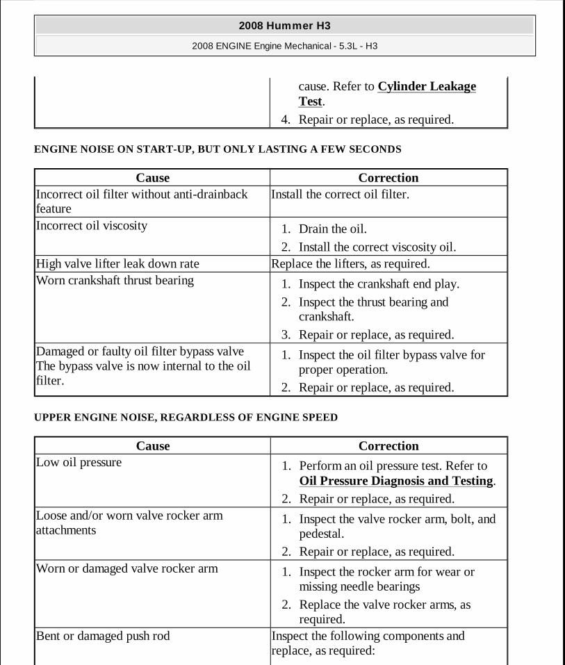
ENGINE NOISE ON START-UP, BUT ONLY LASTING A FEW SECONDS
UPPER ENGINE NOISE, REGARDLESS OF ENGINE SPEED
cause. Refer to Cylinder Leakage Test.
4. Repair or replace, as required.
Cause CorrectionIncorrect oil filter without anti-drainback feature
Install the correct oil filter.
Incorrect oil viscosity 1. Drain the oil. 2. Install the correct viscosity oil.
High valve lifter leak down rate Replace the lifters, as required.Worn crankshaft thrust bearing 1. Inspect the crankshaft end play.
2. Inspect the thrust bearing and crankshaft.
3. Repair or replace, as required. Damaged or faulty oil filter bypass valve The bypass valve is now internal to the oil filter.
1. Inspect the oil filter bypass valve for proper operation.
2. Repair or replace, as required.
Cause CorrectionLow oil pressure 1. Perform an oil pressure test. Refer to
Oil Pressure Diagnosis and Testing. 2. Repair or replace, as required.
Loose and/or worn valve rocker arm attachments
1. Inspect the valve rocker arm, bolt, and pedestal.
2. Repair or replace, as required. Worn or damaged valve rocker arm 1. Inspect the rocker arm for wear or
missing needle bearings 2. Replace the valve rocker arms, as
required. Bent or damaged push rod Inspect the following components and
replace, as required:
2008 Hummer H3
2008 ENGINE Engine Mechanical - 5.3L - H3
MY
Sunday, March 29, 2009 10:47:39 PM Page 37 © 2005 Mitchell Repair Information Company, LLC.
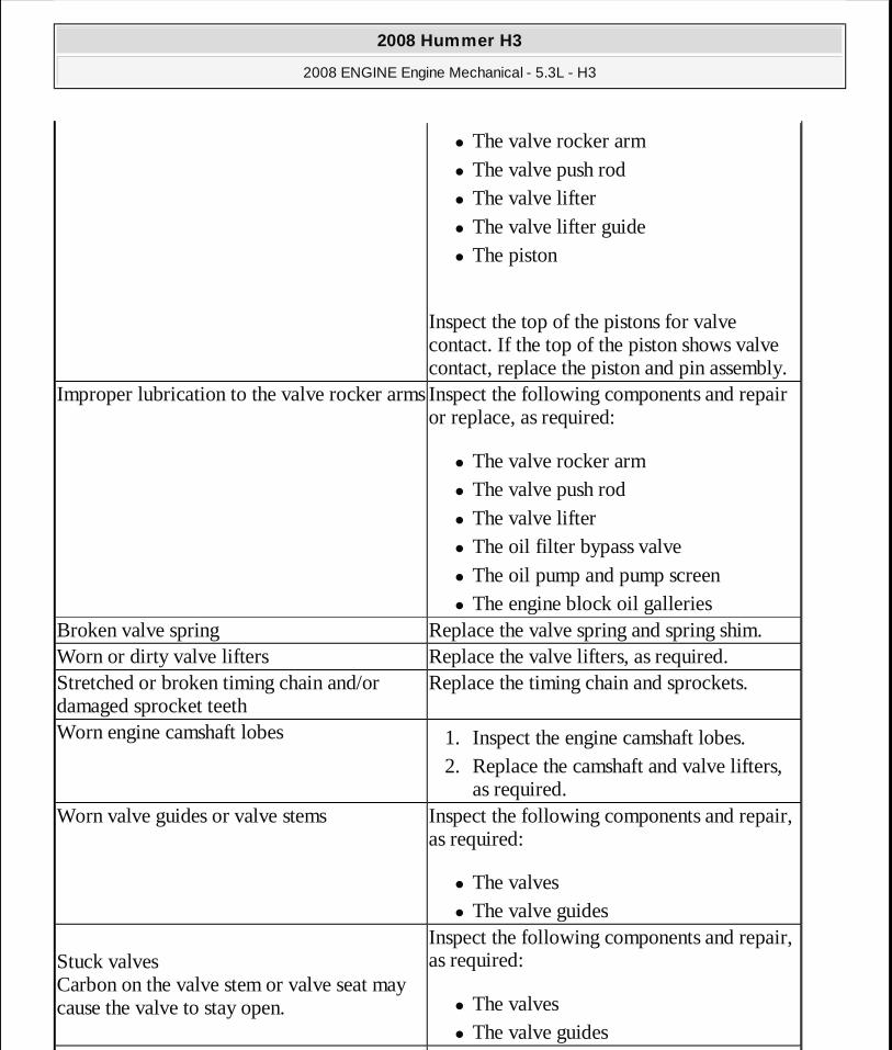
� The valve rocker arm � The valve push rod � The valve lifter � The valve lifter guide � The piston
Inspect the top of the pistons for valve contact. If the top of the piston shows valve contact, replace the piston and pin assembly.
Improper lubrication to the valve rocker armsInspect the following components and repair or replace, as required:
� The valve rocker arm � The valve push rod � The valve lifter � The oil filter bypass valve � The oil pump and pump screen � The engine block oil galleries
Broken valve spring Replace the valve spring and spring shim.Worn or dirty valve lifters Replace the valve lifters, as required.Stretched or broken timing chain and/or damaged sprocket teeth
Replace the timing chain and sprockets.
Worn engine camshaft lobes 1. Inspect the engine camshaft lobes. 2. Replace the camshaft and valve lifters,
as required. Worn valve guides or valve stems Inspect the following components and repair,
as required:
� The valves � The valve guides
Stuck valves Carbon on the valve stem or valve seat may cause the valve to stay open.
Inspect the following components and repair, as required:
� The valves � The valve guides
2008 Hummer H3
2008 ENGINE Engine Mechanical - 5.3L - H3
MY
Sunday, March 29, 2009 10:47:39 PM Page 38 © 2005 Mitchell Repair Information Company, LLC.
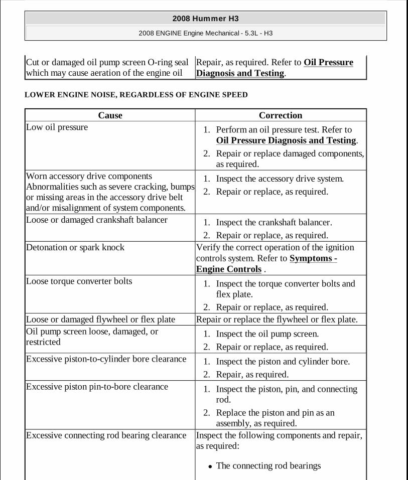
LOWER ENGINE NOISE, REGARDLESS OF ENGINE SPEED
Cut or damaged oil pump screen O-ring seal which may cause aeration of the engine oil
Repair, as required. Refer to Oil Pressure Diagnosis and Testing.
Cause CorrectionLow oil pressure 1. Perform an oil pressure test. Refer to
Oil Pressure Diagnosis and Testing. 2. Repair or replace damaged components,
as required. Worn accessory drive components Abnormalities such as severe cracking, bumps or missing areas in the accessory drive belt and/or misalignment of system components.
1. Inspect the accessory drive system. 2. Repair or replace, as required.
Loose or damaged crankshaft balancer 1. Inspect the crankshaft balancer. 2. Repair or replace, as required.
Detonation or spark knock Verify the correct operation of the ignition controls system. Refer to Symptoms - Engine Controls .
Loose torque converter bolts 1. Inspect the torque converter bolts and flex plate.
2. Repair or replace, as required. Loose or damaged flywheel or flex plate Repair or replace the flywheel or flex plate.Oil pump screen loose, damaged, or restricted
1. Inspect the oil pump screen. 2. Repair or replace, as required.
Excessive piston-to-cylinder bore clearance1. Inspect the piston and cylinder bore. 2. Repair, as required.
Excessive piston pin-to-bore clearance 1. Inspect the piston, pin, and connecting rod.
2. Replace the piston and pin as an assembly, as required.
Excessive connecting rod bearing clearanceInspect the following components and repair, as required:
� The connecting rod bearings
2008 Hummer H3
2008 ENGINE Engine Mechanical - 5.3L - H3
MY
Sunday, March 29, 2009 10:47:39 PM Page 39 © 2005 Mitchell Repair Information Company, LLC.
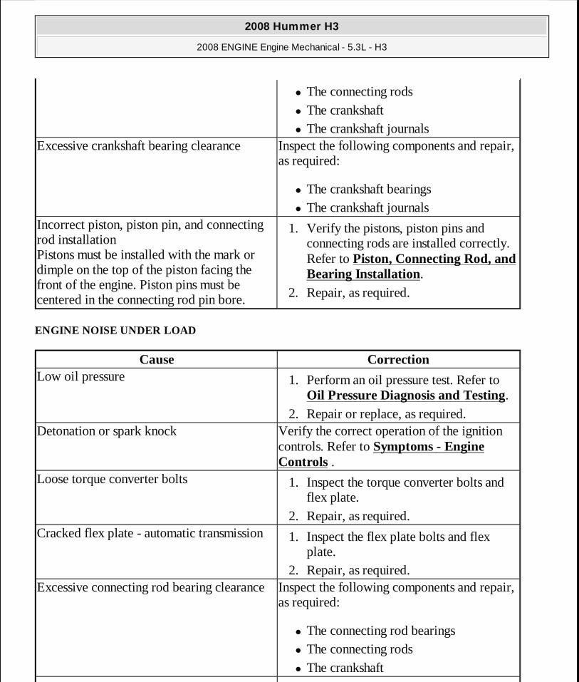
ENGINE NOISE UNDER LOAD
� The connecting rods � The crankshaft � The crankshaft journals
Excessive crankshaft bearing clearance Inspect the following components and repair, as required:
� The crankshaft bearings � The crankshaft journals
Incorrect piston, piston pin, and connecting rod installation Pistons must be installed with the mark or dimple on the top of the piston facing the front of the engine. Piston pins must be centered in the connecting rod pin bore.
1. Verify the pistons, piston pins and connecting rods are installed correctly. Refer to Piston, Connecting Rod, and Bearing Installation.
2. Repair, as required.
Cause CorrectionLow oil pressure 1. Perform an oil pressure test. Refer to
Oil Pressure Diagnosis and Testing. 2. Repair or replace, as required.
Detonation or spark knock Verify the correct operation of the ignition controls. Refer to Symptoms - Engine Controls .
Loose torque converter bolts 1. Inspect the torque converter bolts and flex plate.
2. Repair, as required. Cracked flex plate - automatic transmission 1. Inspect the flex plate bolts and flex
plate. 2. Repair, as required.
Excessive connecting rod bearing clearanceInspect the following components and repair, as required:
� The connecting rod bearings � The connecting rods � The crankshaft
2008 Hummer H3
2008 ENGINE Engine Mechanical - 5.3L - H3
MY
Sunday, March 29, 2009 10:47:39 PM Page 40 © 2005 Mitchell Repair Information Company, LLC.

ENGINE WILL NOT CRANK - CRANKSHAFT WILL NOT ROTATE
Excessive crankshaft bearing clearance Inspect the following components and repair, as required:
� The crankshaft bearings � The crankshaft journals � The cylinder block crankshaft bearing
bore
Cause CorrectionSeized accessory drive system component 1. Remove the accessory drive belts.
2. Confirm that the engine will rotate. Rotate the crankshaft by hand at the crankshaft balancer or flex plate location.
3. Repair or replace the components, as required.
Seized automatic transmission torque converter
1. Remove the torque converter-to-flex plate bolts.
2. Confirm that the engine will rotate. Rotate the crankshaft by hand at the crankshaft balancer or flex plate location.
3. Repair or replace the components, as required.
Broken timing chain 1. Inspect the timing chain and sprockets. 2. Repair or replace the components, as
required. Seized timing chain or timing sprockets 1. Inspect the timing chain and sprockets
for foreign material or a seized chain. 2. Repair or replace the components, as
required. Seized or broken camshaft 1. Inspect the camshaft and the camshaft
bearings. 2. Repair or replace the components, as
2008 Hummer H3
2008 ENGINE Engine Mechanical - 5.3L - H3
MY
Sunday, March 29, 2009 10:47:39 PM Page 41 © 2005 Mitchell Repair Information Company, LLC.

required. Bent valve in the cylinder head 1. Inspect the valves and the cylinder
heads. 2. Repair or replace the components, as
required. Seized oil pump 1. Inspect the oil pump assembly.
2. Repair or replace, as required. Hydraulically locked cylinder
� Coolant/antifreeze in the cylinder � Oil in the cylinder � Fuel in the cylinder
1. Remove the spark plugs and inspect for fluid in the cylinder. When rotating the engine with the spark plugs removed, the piston, on compression stroke, will push fluid from the combustion chamber. Refer to Coolant in Combustion Chamber.
2. Inspect for failed/broken head gaskets. 3. Inspect for a cracked engine block or
cylinder head. 4. Inspect for a sticking fuel injector. 5. Repair or replace the components, as
required. Material in the cylinder
� Broken valve � Broken piston rings � Piston material � Foreign material
1. Inspect the cylinder for damaged components and/or foreign materials.
2. Repair or replace the components, as required.
Seized crankshaft or connecting rod bearings1. Inspect crankshaft and connecting rod bearings.
2. Repair or replace the components, as required.
Bent or broken connecting rod 1. Inspect the connecting rods. 2. Replace the piston and pin as an
assembly, as required. Broken crankshaft 1. Inspect the crankshaft.
2. Repair or replace the components, as
2008 Hummer H3
2008 ENGINE Engine Mechanical - 5.3L - H3
MY
Sunday, March 29, 2009 10:47:39 PM Page 42 © 2005 Mitchell Repair Information Company, LLC.
COOLANT IN COMBUSTION CHAMBER
COOLANT IN ENGINE OIL
required.
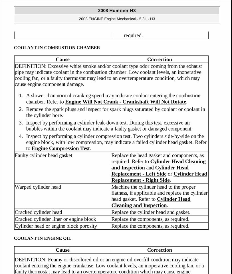
Cause CorrectionDEFINITION: Excessive white smoke and/or coolant type odor coming from the exhaust pipe may indicate coolant in the combustion chamber. Low coolant levels, an inoperative cooling fan, or a faulty thermostat may lead to an overtemperature condition, which may cause engine component damage.
1. A slower than normal cranking speed may indicate coolant entering the combustion chamber. Refer to Engine Will Not Crank - Crankshaft Will Not Rotate.
2. Remove the spark plugs and inspect for spark plugs saturated by coolant or coolant in the cylinder bore.
3. Inspect by performing a cylinder leak-down test. During this test, excessive air bubbles within the coolant may indicate a faulty gasket or damaged component.
4. Inspect by performing a cylinder compression test. Two cylinders side-by-side on the engine block, with low compression, may indicate a failed cylinder head gasket. Refer to Engine Compression Test.
Faulty cylinder head gasket Replace the head gasket and components, as required. Refer to Cylinder Head Cleaning and Inspection and Cylinder Head Replacement - Left Side or Cylinder Head Replacement - Right Side.
Warped cylinder head Machine the cylinder head to the proper flatness, if applicable and replace the cylinder head gasket. Refer to Cylinder Head Cleaning and Inspection.
Cracked cylinder head Replace the cylinder head and gasket.Cracked cylinder liner or engine block Replace the components, as required.Cylinder head or engine block porosity Replace the components, as required.
Cause Correction
DEFINITION: Foamy or discolored oil or an engine oil overfill condition may indicate coolant entering the engine crankcase. Low coolant levels, an inoperative cooling fan, or a faulty thermostat may lead to an overtemperature condition which may cause engine
2008 Hummer H3
2008 ENGINE Engine Mechanical - 5.3L - H3
MY
Sunday, March 29, 2009 10:47:39 PM Page 43 © 2005 Mitchell Repair Information Company, LLC.

ENGINE COMPRESSION TEST
1. Charge the battery if the battery is not fully charged. 2. Disable the ignition system. 3. Disable the fuel injection system. 4. Remove all spark plugs. 5. Turn the ignition to the ON position. 6. Depress the accelerator pedal to position the throttle plate wide open. 7. Start with the compression gage at zero and crank the engine through 4 compression strokes,
4 puffs. 8. Measure the compression for each cylinder. Record the readings. 9. If a cylinder has low compression, inject approximately 15 ml (1 tablespoon) of engine oil
component damage. Contaminated engine oil and oil filter should be changed.
1. Inspect the oil for excessive foaming or an overfill condition. Oil diluted by coolant may not properly lubricate the crankshaft bearings and may lead to component damage. Refer to Lower Engine Noise, Regardless of Engine Speed.
2. Inspect by performing a cylinder leak-down test. During this test, excessive air bubbles within the cooling system may indicate a faulty gasket or damaged component.
3. Inspect by performing a cylinder compression test. 2 cylinders side-by-side on the engine block with low compression may indicate a failed cylinder head gasket. Refer to Engine Compression Test.
Faulty external engine oil cooler Replace the components, as required.Faulty cylinder head gasket Replace the head gasket and components, as
required. Refer to Cylinder Head Cleaning and Inspection and Cylinder Head Replacement - Left Side or Cylinder Head Replacement - Right Side.
Warped cylinder head Machine the cylinder head to proper flatness, if applicable, and replace the cylinder head gasket. Refer to Cylinder Head Cleaning and Inspection.
Cracked cylinder head Replace the cylinder head and gasket.Cracked cylinder liner or engine block Replace the components, as required.Cylinder head, block, or manifold porosityReplace the components, as required.
2008 Hummer H3
2008 ENGINE Engine Mechanical - 5.3L - H3
MY
Sunday, March 29, 2009 10:47:39 PM Page 44 © 2005 Mitchell Repair Information Company, LLC.

into the combustion chamber through the spark plug hole. Measure the compression again and record the reading.
10. The minimum compression in any 1 cylinder should not be less than 70 percent of the highest cylinder. No cylinder should read less than 690 kPa (100 psi). For example, if the highest pressure in any 1 cylinder is 1 035 kPa (150 psi), the lowest allowable pressure for any other cylinder would be 725 kPa (105 psi). (1 035 x 70% = 725) (150 x 70% = 105).
� Normal - Compression builds up quickly and evenly to the specified compression for each cylinder.
� Piston Rings Leaking - Compression is low on the first stroke. Compression builds up with the following strokes, but does not reach normal. Compression improves considerably when you add oil.
� Valves Leaking - Compression is low on the first stroke. Compression usually does not build up on the following strokes. Compression does not improve much when you add oil.
� If 2 adjacent cylinders have lower than normal compression, and injecting oil into the cylinders does not increase the compression, the cause may be a head gasket leaking between the cylinders.
CYLINDER LEAKAGE TEST
Tools Required
J 35667-A Cylinder Head Leakdown Tester, or equivalent
IMPORTANT: A leakage test may be performed in order to measure cylinder/combustion chamber leakage. High cylinder leakage may indicate one or more of the following conditions:
� Worn or burnt valves � Broken valve springs � Stuck valve lifters � Incorrect valve lash � Damaged piston � Worn piston rings � Worn or scored cylinder bore � Damaged cylinder head gasket � Cracked or damaged cylinder head
2008 Hummer H3
2008 ENGINE Engine Mechanical - 5.3L - H3
MY
Sunday, March 29, 2009 10:47:39 PM Page 45 © 2005 Mitchell Repair Information Company, LLC.
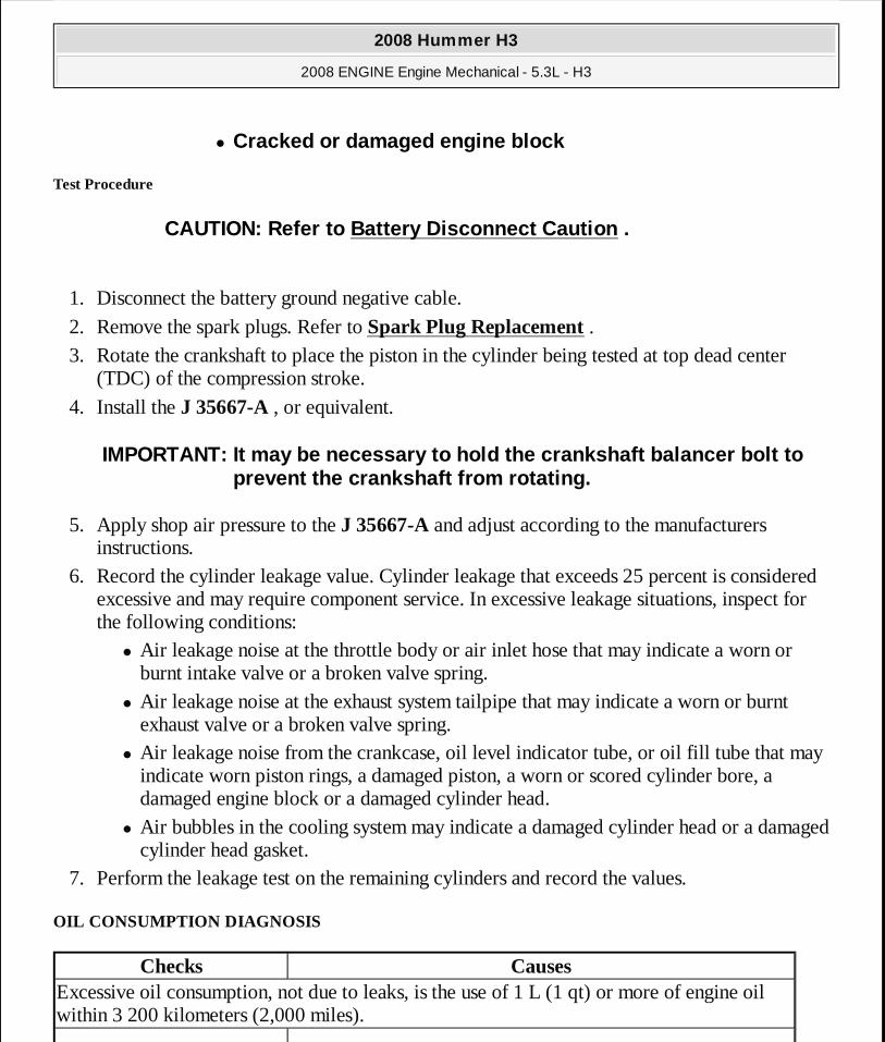
Test Procedure
1. Disconnect the battery ground negative cable.
2. Remove the spark plugs. Refer to Spark Plug Replacement . 3. Rotate the crankshaft to place the piston in the cylinder being tested at top dead center
(TDC) of the compression stroke.
4. Install the J 35667-A , or equivalent.
5. Apply shop air pressure to the J 35667-A and adjust according to the manufacturers instructions.
6. Record the cylinder leakage value. Cylinder leakage that exceeds 25 percent is considered excessive and may require component service. In excessive leakage situations, inspect for the following conditions:
� Air leakage noise at the throttle body or air inlet hose that may indicate a worn or burnt intake valve or a broken valve spring.
� Air leakage noise at the exhaust system tailpipe that may indicate a worn or burnt exhaust valve or a broken valve spring.
� Air leakage noise from the crankcase, oil level indicator tube, or oil fill tube that may indicate worn piston rings, a damaged piston, a worn or scored cylinder bore, a damaged engine block or a damaged cylinder head.
� Air bubbles in the cooling system may indicate a damaged cylinder head or a damaged cylinder head gasket.
7. Perform the leakage test on the remaining cylinders and record the values.
OIL CONSUMPTION DIAGNOSIS
� Cracked or damaged engine block
CAUTION: Refer to Battery Disconnect Caution .
IMPORTANT: It may be necessary to hold the crankshaf t balancer bolt to prevent the crankshaft from rotating.
Checks CausesExcessive oil consumption, not due to leaks, is the use of 1 L (1 qt) or more of engine oil within 3 200 kilometers (2,000 miles).
2008 Hummer H3
2008 ENGINE Engine Mechanical - 5.3L - H3
MY
Sunday, March 29, 2009 10:47:39 PM Page 46 © 2005 Mitchell Repair Information Company, LLC.
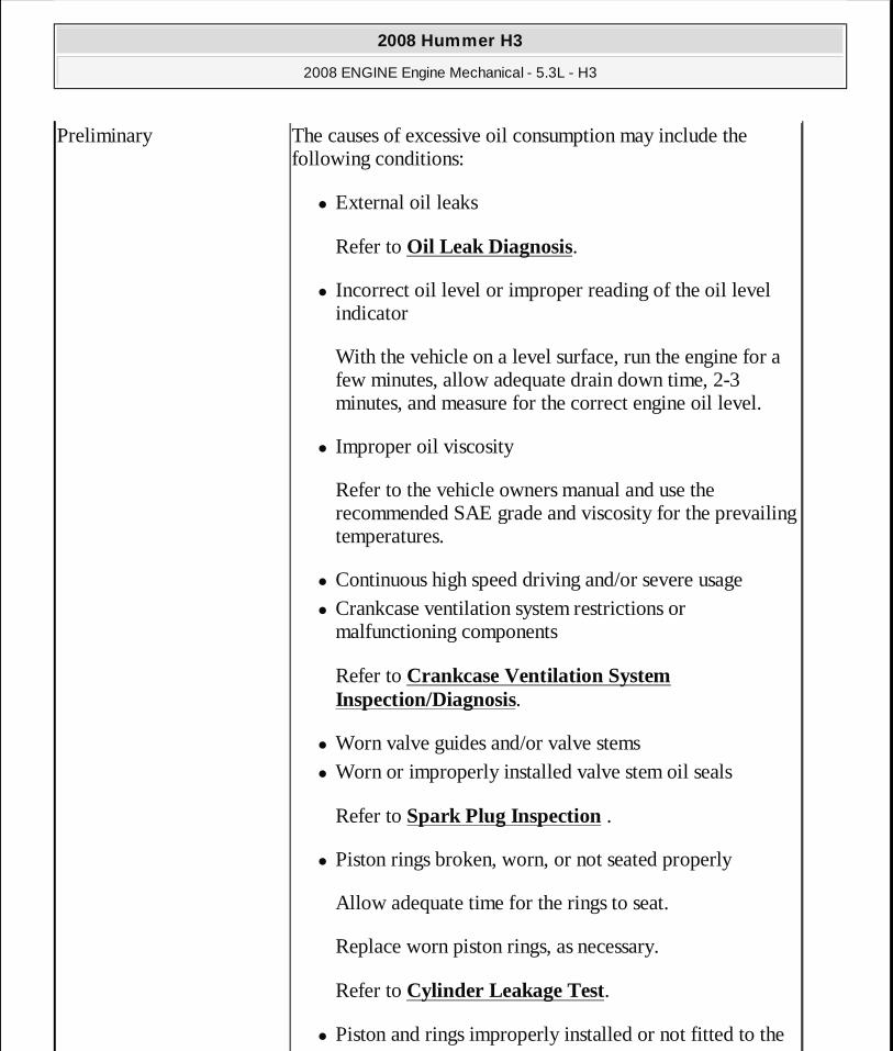
Preliminary The causes of excessive oil consumption may include the following conditions:
� External oil leaks
Refer to Oil Leak Diagnosis.
� Incorrect oil level or improper reading of the oil level indicator
With the vehicle on a level surface, run the engine for a few minutes, allow adequate drain down time, 2-3 minutes, and measure for the correct engine oil level.
� Improper oil viscosity
Refer to the vehicle owners manual and use the recommended SAE grade and viscosity for the prevailing temperatures.
� Continuous high speed driving and/or severe usage � Crankcase ventilation system restrictions or
malfunctioning components
Refer to Crankcase Ventilation System Inspection/Diagnosis.
� Worn valve guides and/or valve stems � Worn or improperly installed valve stem oil seals
Refer to Spark Plug Inspection .
� Piston rings broken, worn, or not seated properly
Allow adequate time for the rings to seat.
Replace worn piston rings, as necessary.
Refer to Cylinder Leakage Test.
� Piston and rings improperly installed or not fitted to the
2008 Hummer H3
2008 ENGINE Engine Mechanical - 5.3L - H3
MY
Sunday, March 29, 2009 10:47:39 PM Page 47 © 2005 Mitchell Repair Information Company, LLC.
OIL PRESSURE DIAGNOSIS AND TESTING
Tools Required
� EN-47971 Oil Pressure Gage Adapter. See Special Tools. � J 21867 Pressure Gage
Test Procedure
cylinder bore
Refer to Lower Engine Noise, Regardless of Engine Speed.
2008 Hummer H3
2008 ENGINE Engine Mechanical - 5.3L - H3
MY
Sunday, March 29, 2009 10:47:39 PM Page 48 © 2005 Mitchell Repair Information Company, LLC.
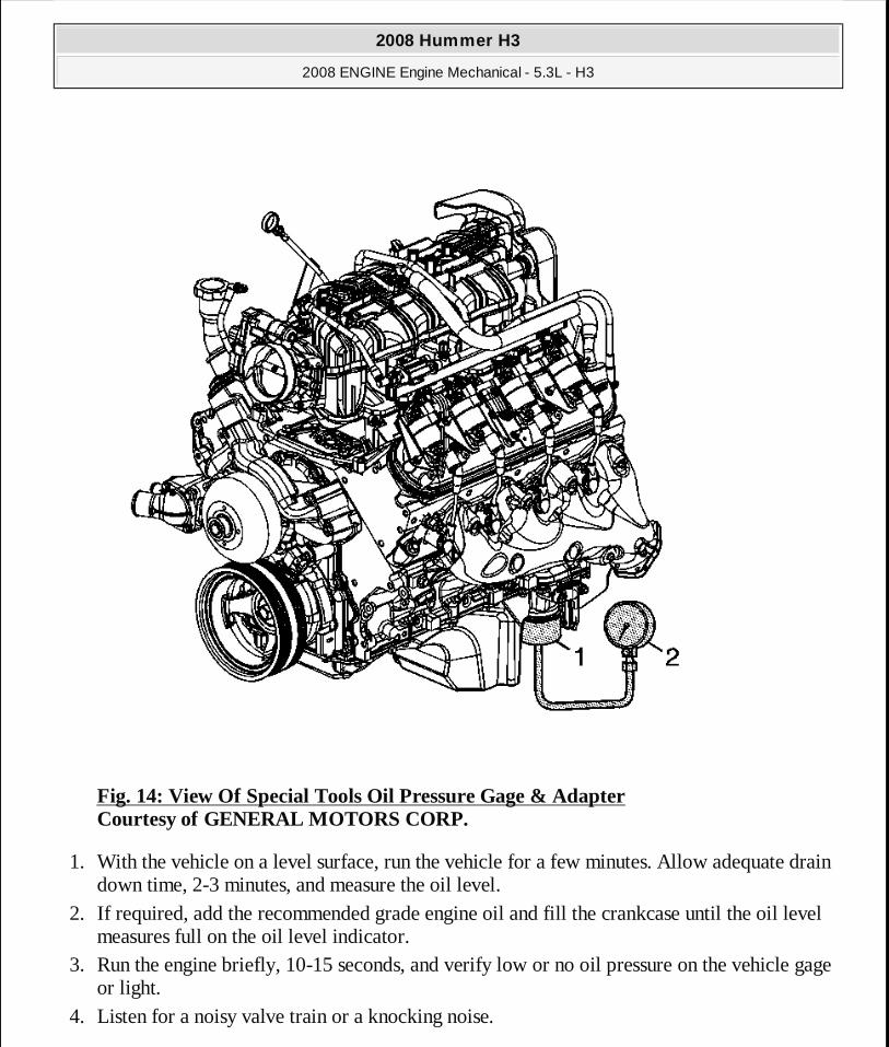
Fig. 14: View Of Special Tools Oil Pressure Gage & Adapter Courtesy of GENERAL MOTORS CORP.
1. With the vehicle on a level surface, run the vehicle for a few minutes. Allow adequate drain down time, 2-3 minutes, and measure the oil level.
2. If required, add the recommended grade engine oil and fill the crankcase until the oil level measures full on the oil level indicator.
3. Run the engine briefly, 10-15 seconds, and verify low or no oil pressure on the vehicle gage or light.
4. Listen for a noisy valve train or a knocking noise.
2008 Hummer H3
2008 ENGINE Engine Mechanical - 5.3L - H3
MY
Sunday, March 29, 2009 10:47:39 PM Page 49 © 2005 Mitchell Repair Information Company, LLC.

5. Inspect for the following conditions: � Oil diluted by water or glycol antifreeze
Refer to Coolant in Engine Oil .
� Foamy oil, which may be caused by a cut or damaged oil pump screen O-ring seal
6. Remove the oil filter and install the EN-47971 (1). See Special Tools. 7. Install the J 21867 (2), or equivalent to the EN-47971 (1). See Special Tools. 8. Run the engine and measure the engine oil pressure.
9. Compare the readings to Engine Mechanical Specifications. 10. If the engine oil pressure is below specifications, inspect the engine for 1 or more of the
following conditions: � Oil pump worn or dirty
Refer to Oil Pump Cleaning and Inspection .
� Oil pump-to-engine block bolts loose
Refer to Oil Pump, Screen and Crankshaft Oil Deflector Installation .
� Oil pump screen loose, plugged, or damaged � Oil pump screen O-ring seal missing or damaged � Malfunctioning oil pump pressure relief valve � Excessive bearing clearance � Cracked, porous, or restricted oil galleries � Oil gallery plugs missing or incorrectly installed
Refer to Engine Block Plug Installation .
OIL LEAK DIAGNOSIS
Step Action Yes NoIMPORTANT:
You can repair most fluid leaks by first visually l ocating the leak, repairing or replacing the component, or by resealing the gasket surface. Once the leak is identified, determine the cause of the leak. Repair the cause of the leak as well as t he leak itself.
1. Operate the vehicle until it reaches normal
2008 Hummer H3
2008 ENGINE Engine Mechanical - 5.3L - H3
MY
Sunday, March 29, 2009 10:47:39 PM Page 50 © 2005 Mitchell Repair Information Company, LLC.

1
operating temperature. 2. Park the vehicle on a level surface, over a
large sheet of paper or other clean surface. 3. Wait 15 minutes. 4. Inspect for drippings.
Are drippings present? Go to Step 2 System OK
2 Can you identify the type of fluid and the approximate location of the leak? Go to Step 10 Go to Step 3
3
1. Visually inspect the suspected area. Use a small mirror to assist in looking at hard to see areas.
2. Inspect for leaks at the following locations: � Sealing surfaces � Fittings � Cracked or damaged components
Can you identify the type of fluid and the approximate location of the leak? Go to Step 10 Go to Step 4
4
1. Completely clean the entire engine and surrounding components.
2. Operate the vehicle for several kilometers, miles, at normal operating temperature and at varying speeds.
3. Park the vehicle on a level surface, over a large sheet of paper or other clean surface.
4. Wait 15 minutes. 5. Identify the type of fluid, and the
approximate location of the leak.
Can you identify the type of fluid and the approximate location of the leak? Go to Step 10 Go to Step 5
1. Visually inspect the suspected area. Use a small mirror to assist in looking at hard to see areas.
2. Inspect for leaks at the following locations:
2008 Hummer H3
2008 ENGINE Engine Mechanical - 5.3L - H3
MY
Sunday, March 29, 2009 10:47:39 PM Page 51 © 2005 Mitchell Repair Information Company, LLC.

5
� Sealing surfaces � Fittings � Cracked or damaged components
Can you identify the type of fluid and the approximate location of the leak? Go to Step 10 Go to Step 6
6
1. Completely clean the entire engine and surrounding components.
2. Apply an aerosol-type powder, baby powder, foot powder, etc., to the suspected area.
3. Operate the vehicle for several kilometers, miles, at normal operating temperature and at varying speeds.
4. Identify the type of fluid, and the approximate location of the leak, from the discolorations in the powder surface.
Can you identify the type of fluid and the approximate location of the leak? Go to Step 10 Go to Step 7
7
1. Visually inspect the suspected area. Use a small mirror to assist in looking at hard to see areas.
2. Inspect for leaks at the following locations: � Sealing surfaces � Fittings � Cracked or damaged components
Can you identify the type of fluid and the approximate location of the leak? Go to Step 10 Go to Step 8
8
Use the J 28428-E high-intensity black light kit in order to identify the type of fluid, and the approximate location of the leak. Refer to the manufacturer's instructions when using the tool. Can you identify the type of fluid and the approximate location of the leak? Go to Step 10 Go to Step 9
2008 Hummer H3
2008 ENGINE Engine Mechanical - 5.3L - H3
MY
Sunday, March 29, 2009 10:47:39 PM Page 52 © 2005 Mitchell Repair Information Company, LLC.
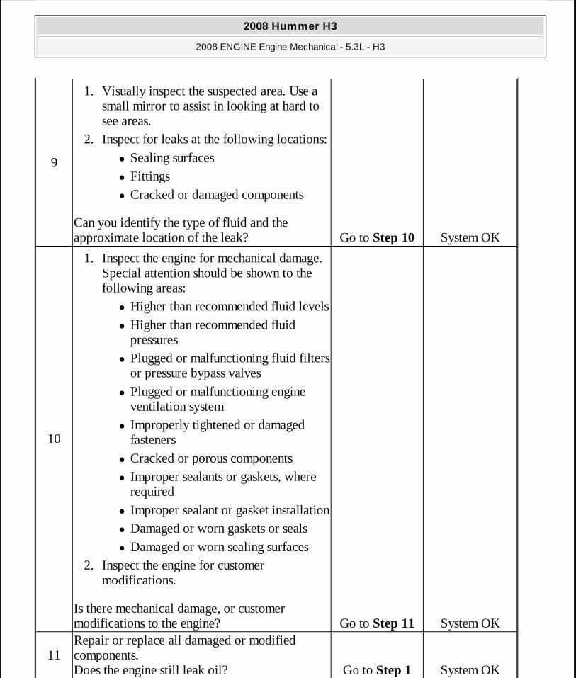
9
1. Visually inspect the suspected area. Use a small mirror to assist in looking at hard to see areas.
2. Inspect for leaks at the following locations: � Sealing surfaces � Fittings � Cracked or damaged components
Can you identify the type of fluid and the approximate location of the leak? Go to Step 10 System OK
10
1. Inspect the engine for mechanical damage. Special attention should be shown to the following areas:
� Higher than recommended fluid levels � Higher than recommended fluid
pressures � Plugged or malfunctioning fluid filters
or pressure bypass valves � Plugged or malfunctioning engine
ventilation system � Improperly tightened or damaged
fasteners � Cracked or porous components � Improper sealants or gaskets, where
required � Improper sealant or gasket installation � Damaged or worn gaskets or seals � Damaged or worn sealing surfaces
2. Inspect the engine for customer modifications.
Is there mechanical damage, or customer modifications to the engine? Go to Step 11 System OK
11Repair or replace all damaged or modified components. Does the engine still leak oil? Go to Step 1 System OK
2008 Hummer H3
2008 ENGINE Engine Mechanical - 5.3L - H3
MY
Sunday, March 29, 2009 10:47:39 PM Page 53 © 2005 Mitchell Repair Information Company, LLC.

CRANKCASE VENTILATION SYSTEM INSPECTION/DIAGNOSIS
DRIVE BELT CHIRPING, SQUEAL, AND WHINE DIAGNOSIS
Diagnostic Aids
� A chirping or squeal noise may be intermittent due to moisture on the drive belts or the pulleys. It may be necessary to spray a small amount of water on the drive belts in order to duplicate the customers concern. If spraying water on the drive belt duplicates the symptom, cleaning the belt pulleys may be the probable solution.
� If the noise is intermittent, verify the accessory drive components by varying their loads making sure they are operated to their maximum capacity. An overcharged A/C system, power steering system with a pinched hose or wrong fluid, or a generator failing are suggested items to inspect.
Symptom CorrectionExternal oil leak Inspect for any of the following conditions:
� Restricted positive crankcase ventilation (PCV) orifice � Restricted or kinked PCV hose or engine vent hose � Damaged, incorrect, or incorrectly installed PCV hose � Excessive crankcase pressure
Rough Idle Inspect for any of the following conditions:
� Restricted PCV orifice � Restricted or kinked PCV hose or engine vent hose � Leaking (damaged) PCV hose � Vacuum hoses worn or not properly installed
Stalling or slow idle speedInspect for any of the following conditions:
� Restricted PCV orifice � Restricted or kinked PCV hose or engine vent hose � Leaking (damaged) PCV hose
High idle speed Inspect for a leaking (damaged) PCV hoseSludge in the engine Inspect for any of the following conditions:
� Restricted PCV orifice � Restricted or kinked PCV hose or engine vent hose
2008 Hummer H3
2008 ENGINE Engine Mechanical - 5.3L - H3
MY
Sunday, March 29, 2009 10:47:39 PM Page 54 © 2005 Mitchell Repair Information Company, LLC.
� A chirping, squeal or whine noise may be caused by a loose or improper installation of a body or suspension component. Other items of the vehicle may also cause the noise.
� The drive belts will not cause a whine noise.
Test Description
The numbers below refer to the step numbers on the diagnostic table.
2: The noise may not be engine related. This step is to verify that the engine is making the noise. If the engine is not making the noise do not proceed further with this table.
3: The noise may be an internal engine noise. Removing the drive belts one at a time and operating the engine for a brief period will verify the noise is related to the drive belt. When removing the drive belt the water pump may not be operating and the engine may overheat. Also DTCs may set when the engine is operating with the drive belts removed.
4: Inspect all drive belt pulleys for pilling. Pilling is the small balls or pills or it can be strings in the drive belt grooves from the accumulation of rubber dust.
6: Misalignment of the pulleys may be caused from improper mounting of the accessory drive component, incorrect installation of the accessory drive component pulley, or the pulley bent inward or outward from a previous repair. Test for a misaligned pulley using a straight edge in the pulley grooves across two or three pulleys. If a misaligned pulley is found refer to that accessory drive component for the proper installation procedure for that pulley.
10: Inspecting of the fasteners can eliminate the possibility that a wrong bolt, nut, spacer, or washer was installed.
12: Inspecting the pulleys for being bent should include inspecting for a dent or other damage to the pulleys that would prevent the drive belt from not seating properly in all of the pulley grooves or on the smooth surface of a pulley when the back side of the belt is used to drive the pulley.
14: This test is to verify that the drive belt tensioner operates properly. If the drive belt tensioner is not operating properly, proper belt tension may not be achieved to keep the drive belt from slipping which could cause a squeal noise.
15: This test is to verify that the drive belt is not too long, which would prevent the drive belt tensioner from working properly. Also if an incorrect length drive belt was installed, it may not be routed properly and may be turning an accessory drive component in the wrong direction.
16: Misalignment of the pulleys may be caused from improper mounting of the accessory drive component, incorrect installation of the accessory drive component pulley, or the pulley bent inward or outward from a previous repair. Test for a misaligned pulley using a
2008 Hummer H3
2008 ENGINE Engine Mechanical - 5.3L - H3
MY
Sunday, March 29, 2009 10:47:39 PM Page 55 © 2005 Mitchell Repair Information Company, LLC.
straight edge in the pulley grooves across two or three pulleys. If a misaligned pulley is found refer to that accessory drive component for the proper installation procedure for that pulley.
17: This test is to verify that the pulleys are the correct diameter or width. Using a known good vehicle compare the pulley sizes.
19: Replacing the drive belt when it is not damaged or there is not excessive pilling will only be a temporary repair.
Step Action Yes No
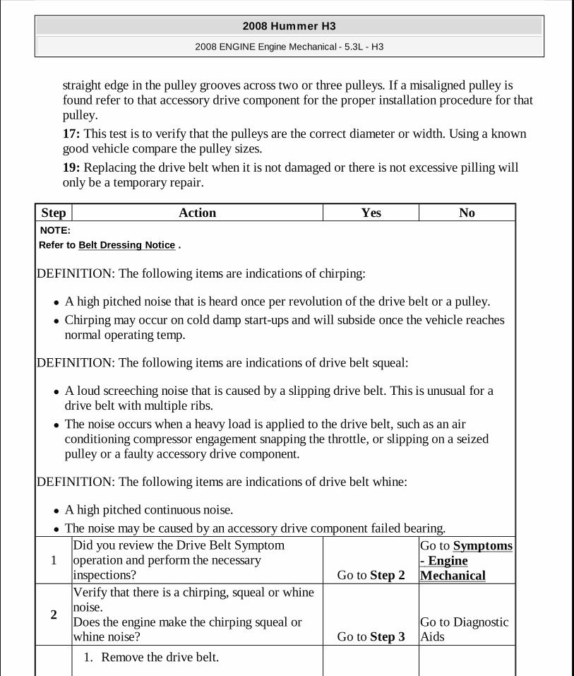
DEFINITION: The following items are indications of chirping:
� A high pitched noise that is heard once per revolution of the drive belt or a pulley. � Chirping may occur on cold damp start-ups and will subside once the vehicle reaches
normal operating temp.
DEFINITION: The following items are indications of drive belt squeal:
� A loud screeching noise that is caused by a slipping drive belt. This is unusual for a drive belt with multiple ribs.
� The noise occurs when a heavy load is applied to the drive belt, such as an air conditioning compressor engagement snapping the throttle, or slipping on a seized pulley or a faulty accessory drive component.
DEFINITION: The following items are indications of drive belt whine:
� A high pitched continuous noise. � The noise may be caused by an accessory drive component failed bearing.
NOTE:Refer to Belt Dressing Notice .
1Did you review the Drive Belt Symptom operation and perform the necessary inspections? Go to Step 2
Go to Symptoms - Engine Mechanical
2
Verify that there is a chirping, squeal or whine noise. Does the engine make the chirping squeal or whine noise? Go to Step 3
Go to Diagnostic Aids
1. Remove the drive belt.
2008 Hummer H3
2008 ENGINE Engine Mechanical - 5.3L - H3
MY
Sunday, March 29, 2009 10:47:39 PM Page 56 © 2005 Mitchell Repair Information Company, LLC.

3
If the engine has multiple drive belts, remove the belts one at a time and perform the test below each time a belt is removed.
2. Operate the engine for no longer than 30-40 seconds.
3. Repeat this test if necessary by removing the remaining belt(s).
Does the chirping, squeal or whine noise still exist?
Go to Symptoms - Engine Mechanical Go to Step 4
4
� If diagnosing a chirping noise, inspect for severe pilling exceeding 1/3 of the belt groove depth.
� If diagnosing a squeal or whine noise, proceed to step 13.
Do the belt grooves have pilling? Go to Step 5 Go to Step 6
5Clean the drive belt pulleys with a suitable wire brush. Did you complete the repair? Go to Step 20 Go to Step 6
6 Inspect for misalignment of the pulleys. Are any of the pulleys misaligned? Go to Step 7 Go to Step 8
7Replace or repair any misaligned pulleys. Did you complete the repair? Go to Step 20 Go to Step 8
8Inspect for bent or cracked brackets. Did you find any bent or cracked brackets? Go to Step 9 Go to Step 10
9Replace any bent or cracked brackets. Did you complete the repair? Go to Step 20 Go to Step 10
10 Inspect for improper, loose or missing fasteners. Did you find the condition? Go to Step 11 Go to Step 12
11 1. Tighten any loose fasteners. Refer to Fastener Tightening Specifications.
2. Replace any improper or missing
NOTE:Refer to Fastener Notice .
2008 Hummer H3
2008 ENGINE Engine Mechanical - 5.3L - H3
MY
Sunday, March 29, 2009 10:47:39 PM Page 57 © 2005 Mitchell Repair Information Company, LLC.

DRIVE BELT RUMBLING AND VIBRATION DIAGNOSIS
Diagnostic Aids
The accessory drive components can have an affect on engine vibration. Vibration from the engine operating may cause a body component or another part of the vehicle to make rumbling noise. Vibration can be caused by, but not limited to the air conditioning (A/C) system over charged, the power steering system restricted or the incorrect fluid, or an extra load on the
fasteners.
Did you complete the repair? Go to Step 20 Go to Step 12
12 Inspect for a bent pulley. Did you find the condition? Go to Step 18 Go to Step 13
13
Inspect for an accessory drive component seized bearing or a faulty accessory drive component. If diagnosing a whine noise and the condition still exist, proceed to Diagnostic Aids. Did you find and correct the condition? Go to Step 20 Go to Step 14
14
Test the drive belt tensioner for proper operation. Refer to Drive Belt Tensioner Diagnosis. Did you find and correct the condition? Go to Step 20 Go to Step 15
15 Inspect for the correct drive belt length. Did you find and correct the condition? Go to Step 20 Go to Step 16
16 Inspect for misalignment of a pulley. Did you find and correct the condition? Go to Step 20 Go to Step 17
17 Inspect for the correct pulley size. Did you find and correct the condition? Go to Step 20
Go to Diagnostic Aids
18Replace the bent pulley. Did you complete the repair? Go to Step 20 Go to Step 19
19
Replace the drive belt. Refer to Drive Belt Replacement - Accessory or Air Conditioning Compressor Belt Replacement (LH8). Did you complete the repair? Go to Step 20
Go to Diagnostic Aids
20Operate the system in order to verify the repair. Did you correct the condition? System OK Go to Step 3
2008 Hummer H3
2008 ENGINE Engine Mechanical - 5.3L - H3
MY
Sunday, March 29, 2009 10:47:39 PM Page 58 © 2005 Mitchell Repair Information Company, LLC.
generator. To help identify an intermittent or an improper condition, vary the loads on the accessory drive components.
The drive belt may have a rumbling condition that can not be seen or felt. Sometimes replacing the drive belt may be the only repair for the symptom.
If replacing the drive belt, completing the diagnostic table, and the noise is only heard when the drive belts are installed, there might be an accessory drive component with a failure. Varying the load on the different accessory drive components may aid in identifying which component is causing the rumbling noise.
Test Description
The numbers below refer to the step numbers on the diagnostic table.
2: This test is to verify that the symptom is present during diagnosing. Other vehicle components may cause a similar symptom.
3: This test is to verify that one of the drive belts is causing the rumbling noise or vibration. Rumbling noise may be confused with an internal engine noise due to the similarity in the description. Remove only one drive belt at a time if the vehicle has multiple drive belts. When removing the drive belts the water pump may not be operating and the engine may overheat. Also DTCs may set when the engine is operating with the drive belts removed.
4: Inspecting the drive belts is to ensure that they are not causing the noise. Small cracks across the ribs of the drive belt will not cause the noise. Belt separation is identified by the plys of the belt separating and may be seen at the edge of the belt or felt as a lump in the belt.
5: Small amounts of pilling is normal condition and acceptable. When the pilling is severe the drive belt does not have a smooth surface for proper operation.
9: Inspecting of the fasteners can eliminate the possibility that the wrong bolt, nut, spacer, or washer was installed.
11: This step should only be performed if the water pump is driven by the drive belt. Inspect the water pump shaft for being bent. Also inspect the water pump bearings for smooth operation and excessive play. Compare the water pump with a known good water pump.
12: Accessory drive component brackets that are bent, cracked, or loose may put extra strain on that accessory component causing it to vibrate.
Step Action Yes NoNOTE:
Refer to Belt Dressing Notice .
2008 Hummer H3
2008 ENGINE Engine Mechanical - 5.3L - H3
MY
Sunday, March 29, 2009 10:47:39 PM Page 59 © 2005 Mitchell Repair Information Company, LLC.
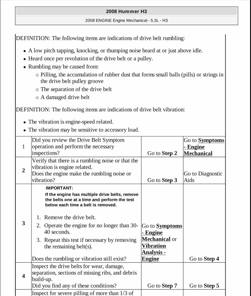
DEFINITION: The following items are indications of drive belt rumbling:
� A low pitch tapping, knocking, or thumping noise heard at or just above idle. � Heard once per revolution of the drive belt or a pulley. � Rumbling may be caused from:
� Pilling, the accumulation of rubber dust that forms small balls (pills) or strings in the drive belt pulley groove
� The separation of the drive belt � A damaged drive belt
DEFINITION: The following items are indications of drive belt vibration:
� The vibration is engine-speed related. � The vibration may be sensitive to accessory load.
1Did you review the Drive Belt Symptom operation and perform the necessary inspections? Go to Step 2
Go to Symptoms - Engine Mechanical
2
Verify that there is a rumbling noise or that the vibration is engine related. Does the engine make the rumbling noise or vibration? Go to Step 3
Go to Diagnostic Aids
3 1. Remove the drive belt. 2. Operate the engine for no longer than 30-
40 seconds. 3. Repeat this test if necessary by removing
the remaining belt(s).
Does the rumbling or vibration still exist?
IMPORTANT:If the engine has multiple drive belts, remove the belts one at a time and perform the test below each time a belt is removed.
Go to Symptoms - Engine Mechanical or Vibration Analysis - Engine Go to Step 4
4
Inspect the drive belts for wear, damage, separation, sections of missing ribs, and debris build-up. Did you find any of these conditions? Go to Step 7 Go to Step 5 Inspect for severe pilling of more than 1/3 of
2008 Hummer H3
2008 ENGINE Engine Mechanical - 5.3L - H3
MY
Sunday, March 29, 2009 10:47:40 PM Page 60 © 2005 Mitchell Repair Information Company, LLC.

DRIVE BELT FALLS OFF AND EXCESSIVE WEAR DIAGNOSIS
5 the drive belt pulley grooves. Did you find severe pilling? Go to Step 6 Go to Step 7
6
1. Clean the drive belt pulleys using a suitable wire brush.
2. Reinstall the drive belts. Refer to Drive Belt Replacement - Accessory or Air Conditioning Compressor Belt Replacement (LH8).
Did you correct the condition? Go to Step 8 Go to Step 7
7
Install a new drive belt. Refer to Drive Belt Replacement - Accessory or Air Conditioning Compressor Belt Replacement (LH8). Did you complete the replacement? Go to Step 8 Go to Step 9
8Operate the system in order to verify the repair. Did you correct the condition? System OK Go to Step 9
9 Inspect for improper, loose or missing fasteners. Did you find any of these conditions? Go to Step 10 Go to Step 11
101. Tighten any loose fasteners. Refer to
Fastener Tightening Specifications. 2. Replace improper or missing fasteners.
Did you complete the repair?
NOTE:
Refer to Fastener Notice .
Go to Step 13 Go to Step 11
11
Inspect for a bent water pump shaft. Refer to Water Pump Replacement (With LH8) or Water Pump Replacement (With LLR) . Did you find and correct the condition? Go to Step 13 Go to Step 12
12 Inspect for bent or cracked brackets. Did you find and correct the condition? Go to Step 13
Go to Diagnostic Aids
13Operate the system in order to verify the repair. Did you correct the condition? System OK Go to Step 3
2008 Hummer H3
2008 ENGINE Engine Mechanical - 5.3L - H3
MY
Sunday, March 29, 2009 10:47:40 PM Page 61 © 2005 Mitchell Repair Information Company, LLC.
Diagnostic Aids
If the drive belt repeatedly falls off the drive belt pulleys, this is because of pulley misalignment.
An extra load that is quickly applied on released by an accessory drive component may cause the drive belt to fall off the pulleys. Verify the accessory drive components operate properly.
If the drive belt is the incorrect length, the drive belt tensioner may not keep the proper tension on the drive belt.
Excessive wear on a drive belt is usually caused by an incorrect installation or the wrong drive belt for the application.
Minor misalignment of the drive belt pulleys will not cause excessive wear, but will probably cause the drive belt to make a noise or to fall off.
Excessive misalignment of the drive belt pulleys will cause excessive wear but may also make the drive belt fall off.
Test Description
The numbers below refer to the step numbers on the diagnostic table.
2: This inspection is to verify the condition of the drive belt. Damage may of occurred to the drive belt when the drive belt fell off. The drive belt may of been damaged, which caused the drive belt to fall off. Inspect the belt for cuts, tears, sections of ribs missing, or damaged belt plys.
4: Misalignment of the pulleys may be caused from improper mounting of the accessory drive component, incorrect installation of the accessory drive component pulley, or the pulley bent inward or outward from a previous repair. Test for a misaligned pulley using a straight edge in the pulley grooves across two or three pulleys. If a misaligned pulley is found refer to that accessory drive component for the proper installation procedure of that pulley.
5: Inspecting the pulleys for being bent should include inspecting for a dent or other damage to the pulleys that would prevent the drive belt from not seating properly in all of the pulley grooves or on the smooth surface of a pulley when the back side of the belt is used to drive the pulley.
6: Accessory drive component brackets that are bent or cracked will let the drive belt fall off.
7: Inspection of the fasteners can eliminate the possibility that a wrong bolt, nut, spacer, or
2008 Hummer H3
2008 ENGINE Engine Mechanical - 5.3L - H3
MY
Sunday, March 29, 2009 10:47:40 PM Page 62 © 2005 Mitchell Repair Information Company, LLC.
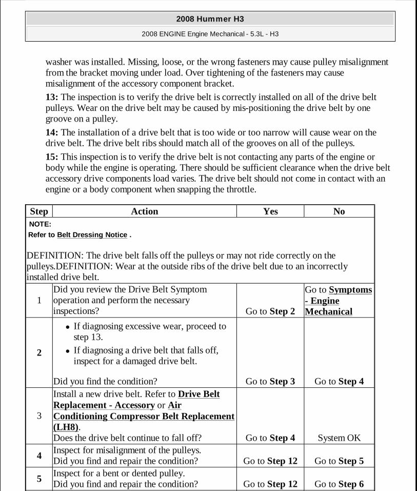
washer was installed. Missing, loose, or the wrong fasteners may cause pulley misalignment from the bracket moving under load. Over tightening of the fasteners may cause misalignment of the accessory component bracket.
13: The inspection is to verify the drive belt is correctly installed on all of the drive belt pulleys. Wear on the drive belt may be caused by mis-positioning the drive belt by one groove on a pulley.
14: The installation of a drive belt that is too wide or too narrow will cause wear on the drive belt. The drive belt ribs should match all of the grooves on all of the pulleys.
15: This inspection is to verify the drive belt is not contacting any parts of the engine or body while the engine is operating. There should be sufficient clearance when the drive belt accessory drive components load varies. The drive belt should not come in contact with an engine or a body component when snapping the throttle.
Step Action Yes No
DEFINITION: The drive belt falls off the pulleys or may not ride correctly on the pulleys.DEFINITION: Wear at the outside ribs of the drive belt due to an incorrectly installed drive belt.
NOTE:Refer to Belt Dressing Notice .
1Did you review the Drive Belt Symptom operation and perform the necessary inspections? Go to Step 2
Go to Symptoms - Engine Mechanical
2
� If diagnosing excessive wear, proceed to step 13.
� If diagnosing a drive belt that falls off, inspect for a damaged drive belt.
Did you find the condition? Go to Step 3 Go to Step 4
3
Install a new drive belt. Refer to Drive Belt Replacement - Accessory or Air Conditioning Compressor Belt Replacement (LH8). Does the drive belt continue to fall off? Go to Step 4 System OK
4 Inspect for misalignment of the pulleys. Did you find and repair the condition? Go to Step 12 Go to Step 5
5 Inspect for a bent or dented pulley. Did you find and repair the condition? Go to Step 12 Go to Step 6
2008 Hummer H3
2008 ENGINE Engine Mechanical - 5.3L - H3
MY
Sunday, March 29, 2009 10:47:40 PM Page 63 © 2005 Mitchell Repair Information Company, LLC.
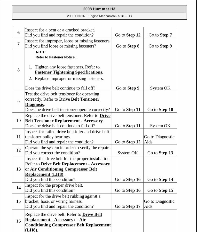
6 Inspect for a bent or a cracked bracket. Did you find and repair the condition? Go to Step 12 Go to Step 7
7 Inspect for improper, loose or missing fasteners. Did you find loose or missing fasteners? Go to Step 8 Go to Step 9
81. Tighten any loose fasteners. Refer to
Fastener Tightening Specifications. 2. Replace improper or missing fasteners.
Does the drive belt continue to fall off?
NOTE:
Refer to Fastener Notice .
Go to Step 9 System OK
9
Test the drive belt tensioner for operating correctly. Refer to Drive Belt Tensioner Diagnosis. Does the drive belt tensioner operate correctly?Go to Step 11 Go to Step 10
10Replace the drive belt tensioner. Refer to Drive Belt Tensioner Replacement - Accessory. Does the drive belt continue to fall off? Go to Step 11 System OK
11Inspect for failed drive belt idler and drive belt tensioner pulley bearings. Did you find and repair the condition? Go to Step 12
Go to Diagnostic Aids
12Operate the system in order to verify the repair. Did you correct the condition? System OK Go to Step 13
13
Inspect the drive belt for the proper installation. Refer to Drive Belt Replacement - Accessory or Air Conditioning Compressor Belt Replacement (LH8). Did you find this condition? Go to Step 16 Go to Step 14
14 Inspect for the proper drive belt. Did you find this condition? Go to Step 16 Go to Step 15
15 Inspect for the drive belt rubbing against a bracket, hose, or wiring harness. Did you find and repair the condition? Go to Step 17
Go to Diagnostic Aids
16
Replace the drive belt. Refer to Drive Belt Replacement - Accessory or Air Conditioning Compressor Belt Replacement (LH8).
2008 Hummer H3
2008 ENGINE Engine Mechanical - 5.3L - H3
MY
Sunday, March 29, 2009 10:47:40 PM Page 64 © 2005 Mitchell Repair Information Company, LLC.

DRIVE BELT TENSIONER DIAGNOSIS
REPAIR INSTRUCTIONS - ON VEHICLE
DRIVE BELT REPLACEMENT - ACCESSORY
Removal Procedure
Did you complete the replacement? Go to Step 17 -
17Operate the system in order to verify the repair. Did you correct the condition? System OK -
Step Action Yes No
1
Remove the drive belt. Refer to Drive Belt Replacement - Accessory. Inspect the drive belt tensioner pulley. Is the drive belt tensioner pulley loose or misaligned? Go to Step 4 Go to Step 2
2Rotate the drive belt tensioner. Does the tensioner rotate without any unusual resistance or binding? Go to Step 3 Go to Step 4
3
1. Use a torque wrench in order to measure the torque required to move the tensioner off of the stop.
2. Use a torque wrench on a known good tensioner in order to measure the torque required to move the tensioner off of the stop.
Is the first torque reading within 10% of the second torque reading? System OK Go to Step 4
4Replace the drive belt tensioner. Refer to Drive Belt Tensioner Replacement - Accessory. Is the repair complete? System OK -
2008 Hummer H3
2008 ENGINE Engine Mechanical - 5.3L - H3
MY
Sunday, March 29, 2009 10:47:40 PM Page 65 © 2005 Mitchell Repair Information Company, LLC.
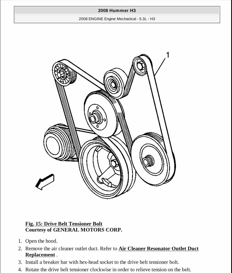
Fig. 15: Drive Belt Tensioner Bolt Courtesy of GENERAL MOTORS CORP.
1. Open the hood.
2. Remove the air cleaner outlet duct. Refer to Air Cleaner Resonator Outlet Duct Replacement .
3. Install a breaker bar with hex-head socket to the drive belt tensioner bolt. 4. Rotate the drive belt tensioner clockwise in order to relieve tension on the belt.
2008 Hummer H3
2008 ENGINE Engine Mechanical - 5.3L - H3
MY
Sunday, March 29, 2009 10:47:40 PM Page 66 © 2005 Mitchell Repair Information Company, LLC.
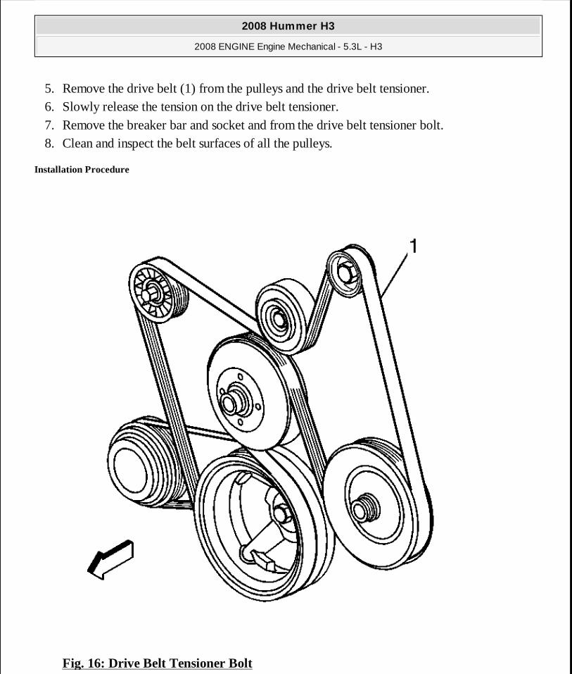
5. Remove the drive belt (1) from the pulleys and the drive belt tensioner. 6. Slowly release the tension on the drive belt tensioner. 7. Remove the breaker bar and socket and from the drive belt tensioner bolt. 8. Clean and inspect the belt surfaces of all the pulleys.
Installation Procedure
Fig. 16: Drive Belt Tensioner Bolt
2008 Hummer H3
2008 ENGINE Engine Mechanical - 5.3L - H3
MY
Sunday, March 29, 2009 10:47:40 PM Page 67 © 2005 Mitchell Repair Information Company, LLC.
Courtesy of GENERAL MOTORS CORP.
1. Route the drive belt (1) around all the pulleys except the idler pulley. 2. Install the breaker bar with hex-head socket to the belt tensioner bolt. 3. Rotate the belt tensioner clockwise in order to relieve the tension on the tensioner. 4. Install the drive belt under the idler pulley. 5. Slowly release the tension on the belt tensioner. 6. Remove the breaker bar and socket from the belt tensioner bolt. 7. Inspect the drive belt for proper installation and alignment.
8. Install the air cleaner outlet duct. Refer to Air Cleaner Resonator Outlet Duct Replacement .
9. Start the vehicle and inspect the drive belt for proper operation. 10. Close the hood.
AIR CONDITIONING COMPRESSOR BELT REPLACEMENT (LH8)
Removal Procedure
2008 Hummer H3
2008 ENGINE Engine Mechanical - 5.3L - H3
MY
Sunday, March 29, 2009 10:47:40 PM Page 68 © 2005 Mitchell Repair Information Company, LLC.

Fig. 17: Removing Belt Courtesy of GENERAL MOTORS CORP.
1. Remove the skid plate. Refer to Engine Shield Replacement . 2. Cut the belt (1) from air conditioning (A/C) and crankshaft pulleys.
Installation Procedure
2008 Hummer H3
2008 ENGINE Engine Mechanical - 5.3L - H3
MY
Sunday, March 29, 2009 10:47:40 PM Page 69 © 2005 Mitchell Repair Information Company, LLC.

Fig. 18: InstallingBelt Courtesy of GENERAL MOTORS CORP.
1. Position the belt behind the rear face of the balancer (1) and off of the A/C pulley (2). 2. Install the belt installation tool (3) onto the balancer.
2008 Hummer H3
2008 ENGINE Engine Mechanical - 5.3L - H3
MY
Sunday, March 29, 2009 10:47:40 PM Page 70 © 2005 Mitchell Repair Information Company, LLC.
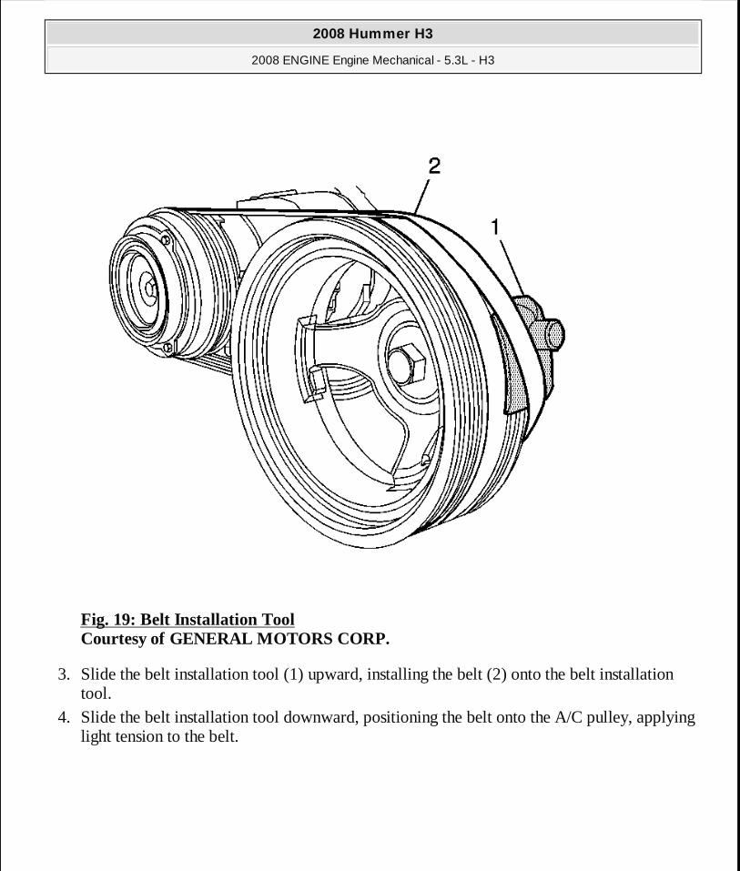
Fig. 19: Belt Installation Tool Courtesy of GENERAL MOTORS CORP.
3. Slide the belt installation tool (1) upward, installing the belt (2) onto the belt installation tool.
4. Slide the belt installation tool downward, positioning the belt onto the A/C pulley, applying light tension to the belt.
2008 Hummer H3
2008 ENGINE Engine Mechanical - 5.3L - H3
MY
Sunday, March 29, 2009 10:47:40 PM Page 71 © 2005 Mitchell Repair Information Company, LLC.

Fig. 20: Locating Lower Portion Of Belt & Ribbed Area Facing Forward Courtesy of GENERAL MOTORS CORP.
5. Position the lower portion of the belt (1) with the ribbed area facing forward.
2008 Hummer H3
2008 ENGINE Engine Mechanical - 5.3L - H3
MY
Sunday, March 29, 2009 10:47:40 PM Page 72 © 2005 Mitchell Repair Information Company, LLC.
Fig. 21: Rotating Crankshaft Pulley Courtesy of GENERAL MOTORS CORP.
6. Slowly rotate the crankshaft pulley (1) in a clockwise direction while using finger pressure to pull the belt (2) forward. Ensure that the ribbed area of the belt remains facing forward and the belt aligns properly to the A/C pulley.
2008 Hummer H3
2008 ENGINE Engine Mechanical - 5.3L - H3
MY
Sunday, March 29, 2009 10:47:40 PM Page 73 © 2005 Mitchell Repair Information Company, LLC.
Fig. 22: Drive Belt Alignment Courtesy of GENERAL MOTORS CORP.
7. Inspect the drive belt (1) for proper installation and alignment.
2008 Hummer H3
2008 ENGINE Engine Mechanical - 5.3L - H3
MY
Sunday, March 29, 2009 10:47:40 PM Page 74 © 2005 Mitchell Repair Information Company, LLC.
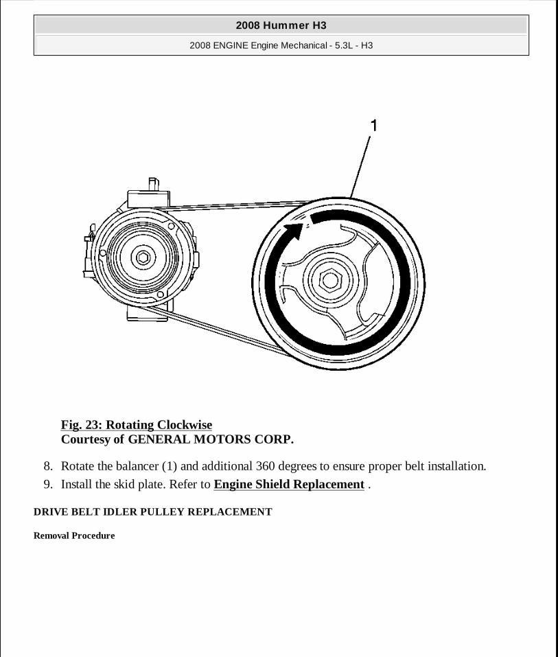
Fig. 23: Rotating Clockwise Courtesy of GENERAL MOTORS CORP.
8. Rotate the balancer (1) and additional 360 degrees to ensure proper belt installation.
9. Install the skid plate. Refer to Engine Shield Replacement .
DRIVE BELT IDLER PULLEY REPLACEMENT
Removal Procedure
2008 Hummer H3
2008 ENGINE Engine Mechanical - 5.3L - H3
MY
Sunday, March 29, 2009 10:47:40 PM Page 75 © 2005 Mitchell Repair Information Company, LLC.
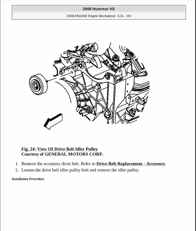
Fig. 24: View Of Drive Belt Idler Pulley Courtesy of GENERAL MOTORS CORP.
1. Remove the accessory drive belt. Refer to Drive Belt Replacement - Accessory. 2. Loosen the drive belt idler pulley bolt and remove the idler pulley.
Installation Procedure
2008 Hummer H3
2008 ENGINE Engine Mechanical - 5.3L - H3
MY
Sunday, March 29, 2009 10:47:40 PM Page 76 © 2005 Mitchell Repair Information Company, LLC.

Fig. 25: View Of Drive Belt Idler Pulley Courtesy of GENERAL MOTORS CORP.
1. Position the drive belt idler pulley to the generator bracket and tighten the idler pulley bolt finger tight.
2. Tighten the drive belt idler pulley bolt.
Tighten: Tighten the bolt to 50 N.m (37 lb ft).
3. Install the accessory drive belt. Refer to Drive Belt Replacement - Accessory.
DRIVE BELT TENSIONER REPLACEMENT - ACCESSORY
Removal Procedure
NOTE: Refer to Fastener Notice .
2008 Hummer H3
2008 ENGINE Engine Mechanical - 5.3L - H3
MY
Sunday, March 29, 2009 10:47:40 PM Page 77 © 2005 Mitchell Repair Information Company, LLC.
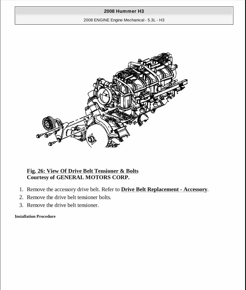
Fig. 26: View Of Drive Belt Tensioner & Bolts Courtesy of GENERAL MOTORS CORP.
1. Remove the accessory drive belt. Refer to Drive Belt Replacement - Accessory. 2. Remove the drive belt tensioner bolts. 3. Remove the drive belt tensioner.
Installation Procedure
2008 Hummer H3
2008 ENGINE Engine Mechanical - 5.3L - H3
MY
Sunday, March 29, 2009 10:47:40 PM Page 78 © 2005 Mitchell Repair Information Company, LLC.
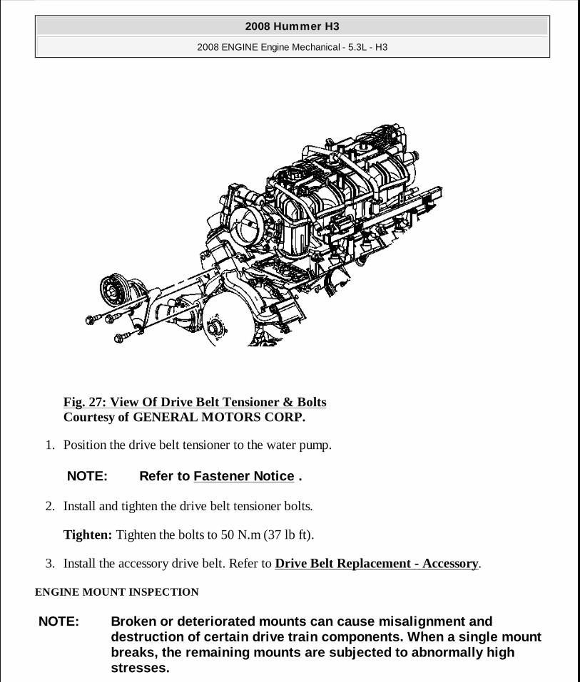
Fig. 27: View Of Drive Belt Tensioner & Bolts Courtesy of GENERAL MOTORS CORP.
1. Position the drive belt tensioner to the water pump.
2. Install and tighten the drive belt tensioner bolts.
Tighten: Tighten the bolts to 50 N.m (37 lb ft).
3. Install the accessory drive belt. Refer to Drive Belt Replacement - Accessory.
ENGINE MOUNT INSPECTION
NOTE: Refer to Fastener Notice .
NOTE: Broken or deteriorated mounts can cause misali gnment and destruction of certain drive train components. When a single mount breaks, the remaining mounts are subjected to abnor mally high stresses.
2008 Hummer H3
2008 ENGINE Engine Mechanical - 5.3L - H3
MY
Sunday, March 29, 2009 10:47:40 PM Page 79 © 2005 Mitchell Repair Information Company, LLC.

Visual/Physical Inspection
1. Support the powertrain using the appropriate support method; refer to the powertrain mount replacement procedure. Raising the powertrain removes the weight from the engine mount and creates slight tension in the rubber.
2. Clean the mount and surrounding area to ensure good visibility of the mount condition.
3. Verify all attaching fasteners are present and at the correct torque. Refer to Engine Mount Replacement - Left Side and/or Engine Mount Replacement - Right Side for any torque sequencing and/or torque specifications.
4. Slightly raise the engine approximately 5-7 mm. 5. Inspect the mount for any of the following conditions:
� Hard rubber surfaces - covered with extreme heat check cracks. � Rubber separation from the metal plate of the engine mount. � Rubber is split through the center of the engine mount.
� If equipped with a hydraulic mount, inspect for GLYCOL™ fluid leaking from the engine mount.
ENGINE MOUNT REPLACEMENT - LEFT SIDE
Removal Procedure
NOTE: When raising or supporting the engine for any reason, do not use a jack under the oil pan, any sheet metal, or the cra nkshaft pulley. Due to the small clearance between the oil pan and the oil pump screen, jacking against the oil pan may cause the p an to be bent against the pump screen. This will result in a dama ged oil pickup unit.
IMPORTANT: Observe the engine mount while raising th e engine. If the engine mount exhibits any of the following conditio ns the mount may require replacement. Refer to Engine Moun t Replacement - Left Side and/or Engine Mount Replacement - Right Side .
IMPORTANT: Before replacing any engine mount due to suspected fluid loss, verify that the source of the fluid is from the engine mount , and not the engine or an external so urce.
2008 Hummer H3
2008 ENGINE Engine Mechanical - 5.3L - H3
MY
Sunday, March 29, 2009 10:47:40 PM Page 80 © 2005 Mitchell Repair Information Company, LLC.
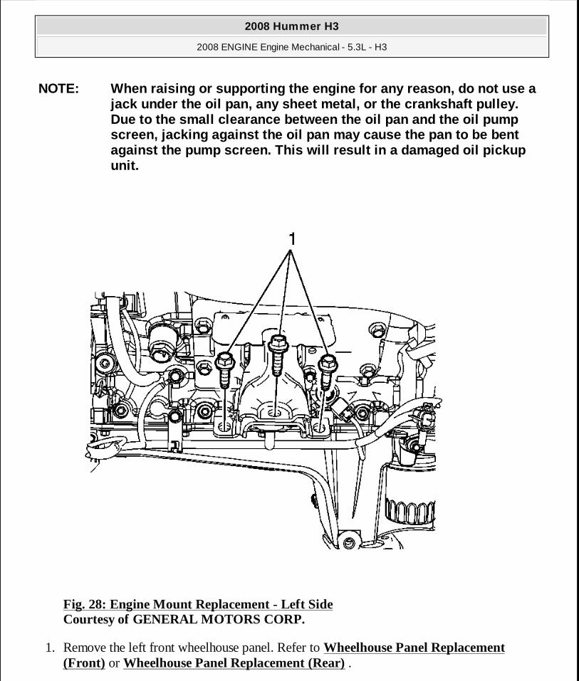
Fig. 28: Engine Mount Replacement - Left Side Courtesy of GENERAL MOTORS CORP.
1. Remove the left front wheelhouse panel. Refer to Wheelhouse Panel Replacement (Front) or Wheelhouse Panel Replacement (Rear) .
NOTE: When raising or supporting the engine for any reason, do not use a jack under the oil pan, any sheet metal, or the cra nkshaft pulley. Due to the small clearance between the oil pan and the oil pump screen, jacking against the oil pan may cause the p an to be bent against the pump screen. This will result in a dama ged oil pickup unit.
2008 Hummer H3
2008 ENGINE Engine Mechanical - 5.3L - H3
MY
Sunday, March 29, 2009 10:47:40 PM Page 81 © 2005 Mitchell Repair Information Company, LLC.

2. Remove the engine protection shield. Refer to Engine Shield Replacement . 3. Remove the oil pan skid plate. Refer to Oil Pan Skid Plate Replacement . 4. Remove the wheelhouse liner. Refer to Wheelhouse Panel Replacement (Front) or
Wheelhouse Panel Replacement (Rear) . 5. Remove the engine mount to frame bolts (1).
Fig. 29: Engine Mount & Frame Bolts Courtesy of GENERAL MOTORS CORP.
2008 Hummer H3
2008 ENGINE Engine Mechanical - 5.3L - H3
MY
Sunday, March 29, 2009 10:47:40 PM Page 82 © 2005 Mitchell Repair Information Company, LLC.
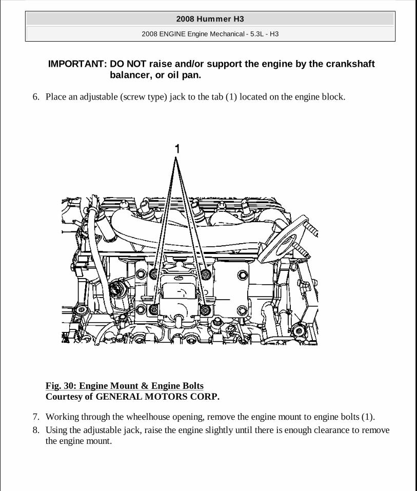
6. Place an adjustable (screw type) jack to the tab (1) located on the engine block.
Fig. 30: Engine Mount & Engine Bolts Courtesy of GENERAL MOTORS CORP.
7. Working through the wheelhouse opening, remove the engine mount to engine bolts (1). 8. Using the adjustable jack, raise the engine slightly until there is enough clearance to remove
the engine mount.
IMPORTANT: DO NOT raise and/or support the engine by the crankshaft balancer, or oil pan.
2008 Hummer H3
2008 ENGINE Engine Mechanical - 5.3L - H3
MY
Sunday, March 29, 2009 10:47:40 PM Page 83 © 2005 Mitchell Repair Information Company, LLC.
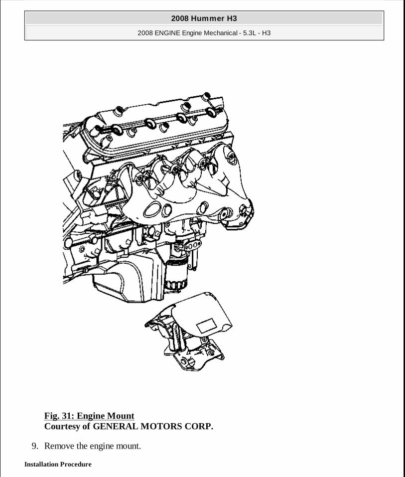
Fig. 31: Engine Mount Courtesy of GENERAL MOTORS CORP.
9. Remove the engine mount.
Installation Procedure
2008 Hummer H3
2008 ENGINE Engine Mechanical - 5.3L - H3
MY
Sunday, March 29, 2009 10:47:40 PM Page 84 © 2005 Mitchell Repair Information Company, LLC.

Fig. 32: Engine Mount Courtesy of GENERAL MOTORS CORP.
1. Position the engine mount to the engine.
2008 Hummer H3
2008 ENGINE Engine Mechanical - 5.3L - H3
MY
Sunday, March 29, 2009 10:47:40 PM Page 85 © 2005 Mitchell Repair Information Company, LLC.

Fig. 33: Engine Mount & Engine Bolts Courtesy of GENERAL MOTORS CORP.
2. Working through the wheelhouse opening, install the engine mount to engine nuts (1).
Tighten: Tighten the bolts to 55 N.m (41 lb ft).
3. Using the adjustable jack, lower the engine until the engine mount is sitting flush on the frame.
4. Remove the adjustable jack from the engine block.
NOTE: Refer to Fastener Notice .
2008 Hummer H3
2008 ENGINE Engine Mechanical - 5.3L - H3
MY
Sunday, March 29, 2009 10:47:40 PM Page 86 © 2005 Mitchell Repair Information Company, LLC.
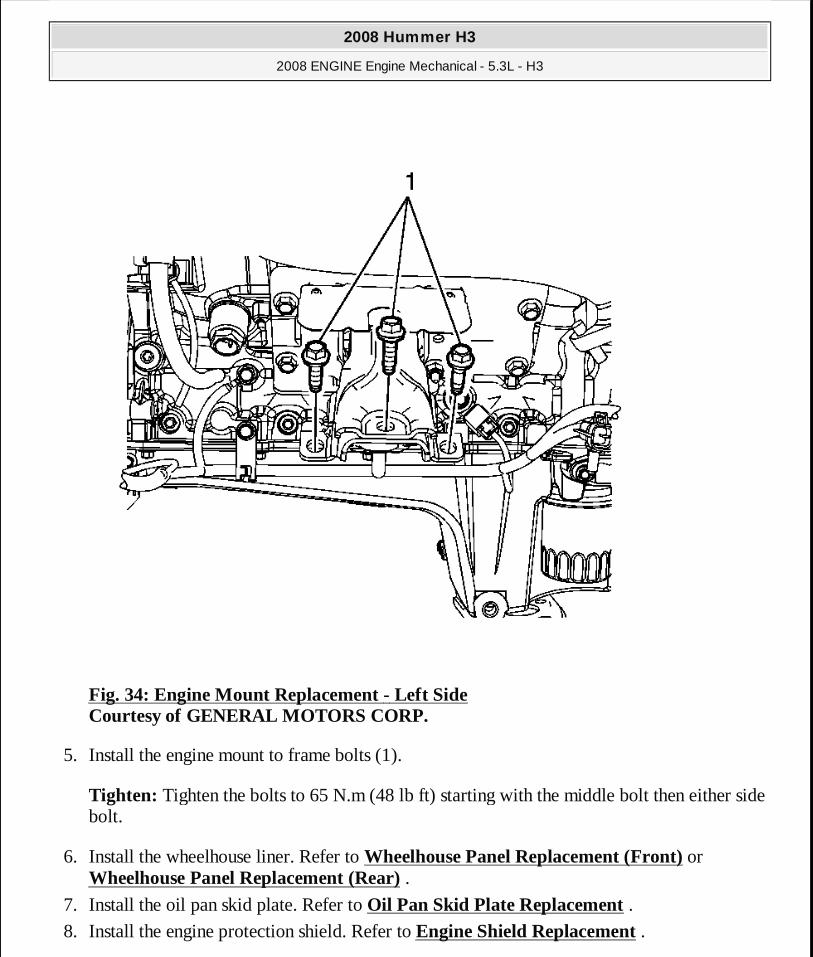
Fig. 34: Engine Mount Replacement - Left Side Courtesy of GENERAL MOTORS CORP.
5. Install the engine mount to frame bolts (1).
Tighten: Tighten the bolts to 65 N.m (48 lb ft) starting with the middle bolt then either side bolt.
6. Install the wheelhouse liner. Refer to Wheelhouse Panel Replacement (Front) or Wheelhouse Panel Replacement (Rear) .
7. Install the oil pan skid plate. Refer to Oil Pan Skid Plate Replacement . 8. Install the engine protection shield. Refer to Engine Shield Replacement .
2008 Hummer H3
2008 ENGINE Engine Mechanical - 5.3L - H3
MY
Sunday, March 29, 2009 10:47:40 PM Page 87 © 2005 Mitchell Repair Information Company, LLC.
9. Install the left front wheelhouse panel. Refer to Wheelhouse Panel Replacement (Front) or Wheelhouse Panel Replacement (Rear) .
10. Lower the vehicle.
ENGINE MOUNT REPLACEMENT - RIGHT SIDE
Removal Procedure
NOTE: When raising or supporting the engine for any reason, do not use a jack under the oil pan, any sheet metal, or the cra nkshaft pulley. Due to the small clearance between the oil pan and the oil pump screen, jacking against the oil pan may cause the p an to be bent against the pump screen. This will result in a dama ged oil pickup unit.
2008 Hummer H3
2008 ENGINE Engine Mechanical - 5.3L - H3
MY
Sunday, March 29, 2009 10:47:40 PM Page 88 © 2005 Mitchell Repair Information Company, LLC.
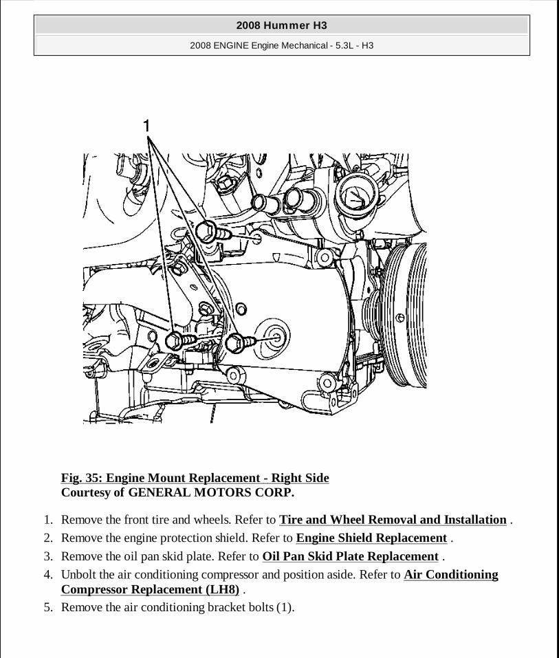
Fig. 35: Engine Mount Replacement - Right Side Courtesy of GENERAL MOTORS CORP.
1. Remove the front tire and wheels. Refer to Tire and Wheel Removal and Installation .
2. Remove the engine protection shield. Refer to Engine Shield Replacement . 3. Remove the oil pan skid plate. Refer to Oil Pan Skid Plate Replacement . 4. Unbolt the air conditioning compressor and position aside. Refer to Air Conditioning
Compressor Replacement (LH8) . 5. Remove the air conditioning bracket bolts (1).
2008 Hummer H3
2008 ENGINE Engine Mechanical - 5.3L - H3
MY
Sunday, March 29, 2009 10:47:40 PM Page 89 © 2005 Mitchell Repair Information Company, LLC.
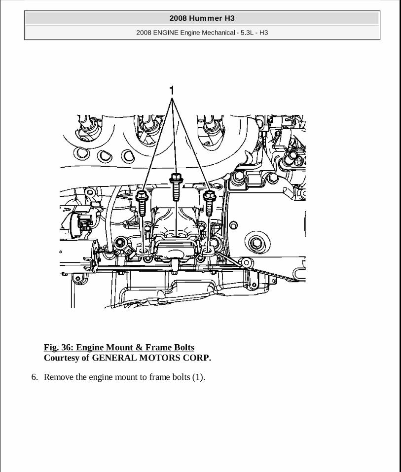
Fig. 36: Engine Mount & Frame Bolts Courtesy of GENERAL MOTORS CORP.
6. Remove the engine mount to frame bolts (1).
2008 Hummer H3
2008 ENGINE Engine Mechanical - 5.3L - H3
MY
Sunday, March 29, 2009 10:47:40 PM Page 90 © 2005 Mitchell Repair Information Company, LLC.
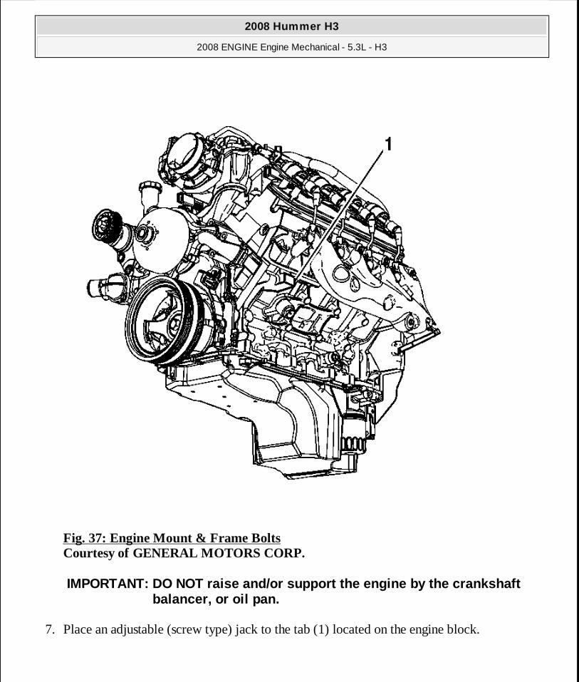
Fig. 37: Engine Mount & Frame Bolts Courtesy of GENERAL MOTORS CORP.
7. Place an adjustable (screw type) jack to the tab (1) located on the engine block.
IMPORTANT: DO NOT raise and/or support the engine by the crankshaft balancer, or oil pan.
2008 Hummer H3
2008 ENGINE Engine Mechanical - 5.3L - H3
MY
Sunday, March 29, 2009 10:47:41 PM Page 91 © 2005 Mitchell Repair Information Company, LLC.
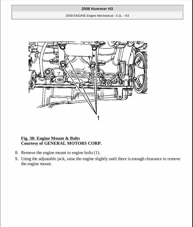
Fig. 38: Engine Mount & Bolts Courtesy of GENERAL MOTORS CORP.
8. Remove the engine mount to engine bolts (1). 9. Using the adjustable jack, raise the engine slightly until there is enough clearance to remove
the engine mount.
2008 Hummer H3
2008 ENGINE Engine Mechanical - 5.3L - H3
MY
Sunday, March 29, 2009 10:47:41 PM Page 92 © 2005 Mitchell Repair Information Company, LLC.

Fig. 39: Locating Engine Mount Courtesy of GENERAL MOTORS CORP.
10. Remove the engine mount (1).
Installation Procedure
2008 Hummer H3
2008 ENGINE Engine Mechanical - 5.3L - H3
MY
Sunday, March 29, 2009 10:47:41 PM Page 93 © 2005 Mitchell Repair Information Company, LLC.

Fig. 40: Locating Engine Mount Courtesy of GENERAL MOTORS CORP.
1. Position the engine mount (1) to the engine.
2008 Hummer H3
2008 ENGINE Engine Mechanical - 5.3L - H3
MY
Sunday, March 29, 2009 10:47:41 PM Page 94 © 2005 Mitchell Repair Information Company, LLC.
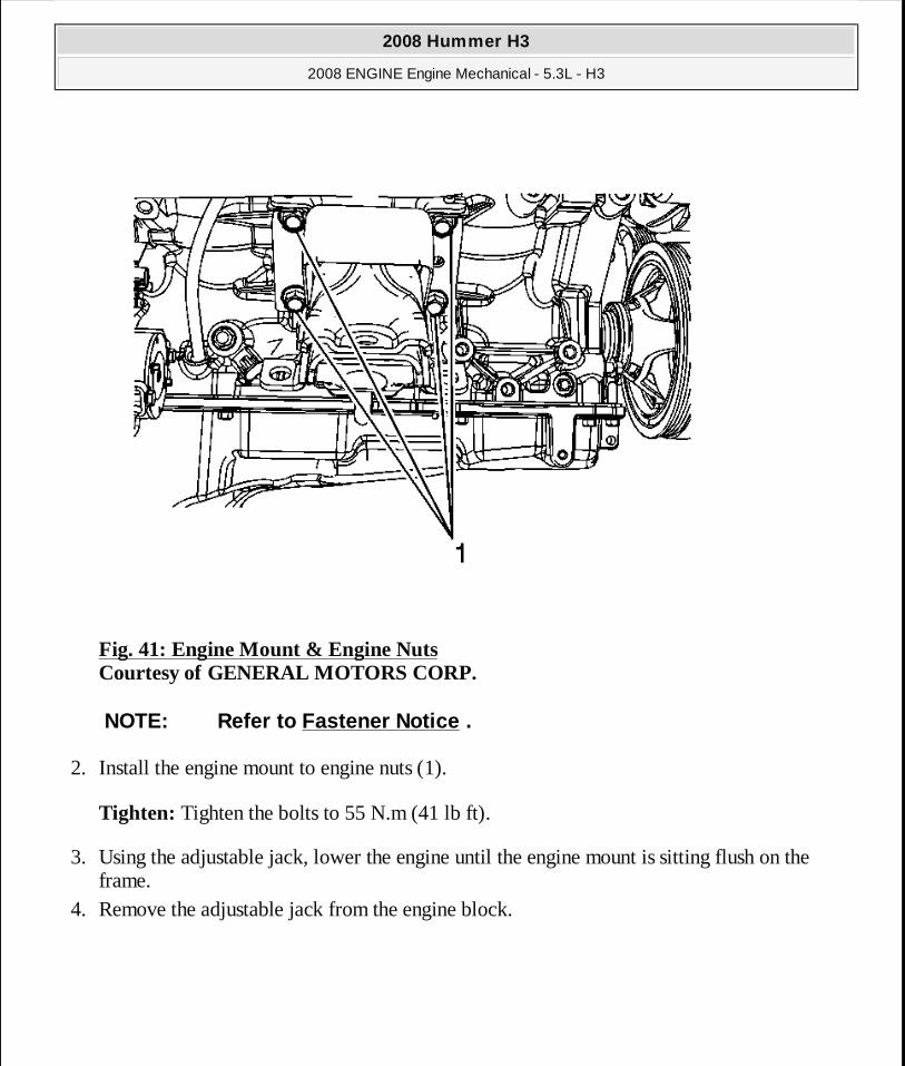
Fig. 41: Engine Mount & Engine Nuts Courtesy of GENERAL MOTORS CORP.
2. Install the engine mount to engine nuts (1).
Tighten: Tighten the bolts to 55 N.m (41 lb ft).
3. Using the adjustable jack, lower the engine until the engine mount is sitting flush on the frame.
4. Remove the adjustable jack from the engine block.
NOTE: Refer to Fastener Notice .
2008 Hummer H3
2008 ENGINE Engine Mechanical - 5.3L - H3
MY
Sunday, March 29, 2009 10:47:41 PM Page 95 © 2005 Mitchell Repair Information Company, LLC.
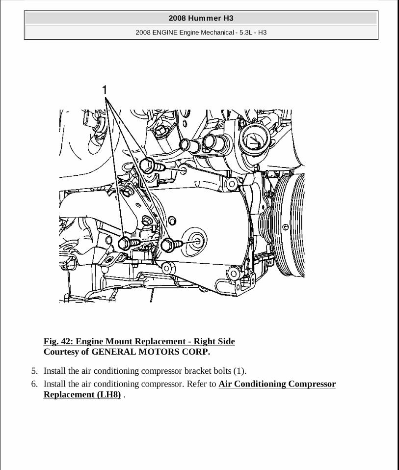
Fig. 42: Engine Mount Replacement - Right Side Courtesy of GENERAL MOTORS CORP.
5. Install the air conditioning compressor bracket bolts (1).
6. Install the air conditioning compressor. Refer to Air Conditioning Compressor Replacement (LH8) .
2008 Hummer H3
2008 ENGINE Engine Mechanical - 5.3L - H3
MY
Sunday, March 29, 2009 10:47:41 PM Page 96 © 2005 Mitchell Repair Information Company, LLC.

Fig. 43: Engine Mount & Frame Bolts Courtesy of GENERAL MOTORS CORP.
7. Install the engine mount to frame bolts (1).
Tighten: Tighten the bolts to 65 N.m (48 lb ft) starting with the middle bolt then either side bolt.
8. Install the oil pan skid plate. Refer to Oil Pan Skid Plate Replacement . 9. Install the engine protection shield. Refer to Engine Shield Replacement .
10. Install the front tire and wheels. Refer to Tire and Wheel Removal and Installation . 11. Lower the vehicle.
2008 Hummer H3
2008 ENGINE Engine Mechanical - 5.3L - H3
MY
Sunday, March 29, 2009 10:47:41 PM Page 97 © 2005 Mitchell Repair Information Company, LLC.
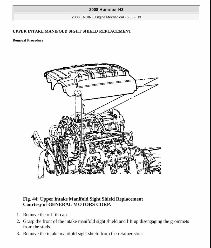
UPPER INTAKE MANIFOLD SIGHT SHIELD REPLACEMENT
Removal Procedure
Fig. 44: Upper Intake Manifold Sight Shield Replacement Courtesy of GENERAL MOTORS CORP.
1. Remove the oil fill cap. 2. Grasp the front of the intake manifold sight shield and lift up disengaging the grommets
from the studs. 3. Remove the intake manifold sight shield from the retainer slots.
2008 Hummer H3
2008 ENGINE Engine Mechanical - 5.3L - H3
MY
Sunday, March 29, 2009 10:47:41 PM Page 98 © 2005 Mitchell Repair Information Company, LLC.
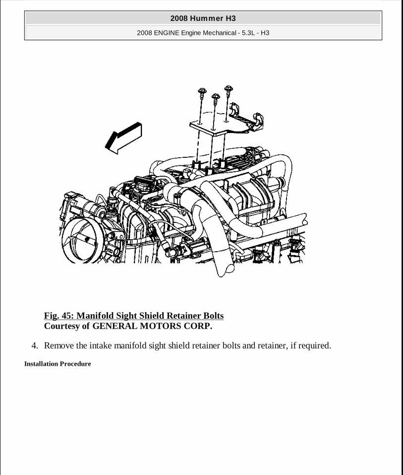
Fig. 45: Manifold Sight Shield Retainer Bolts Courtesy of GENERAL MOTORS CORP.
4. Remove the intake manifold sight shield retainer bolts and retainer, if required.
Installation Procedure
2008 Hummer H3
2008 ENGINE Engine Mechanical - 5.3L - H3
MY
Sunday, March 29, 2009 10:47:41 PM Page 99 © 2005 Mitchell Repair Information Company, LLC.
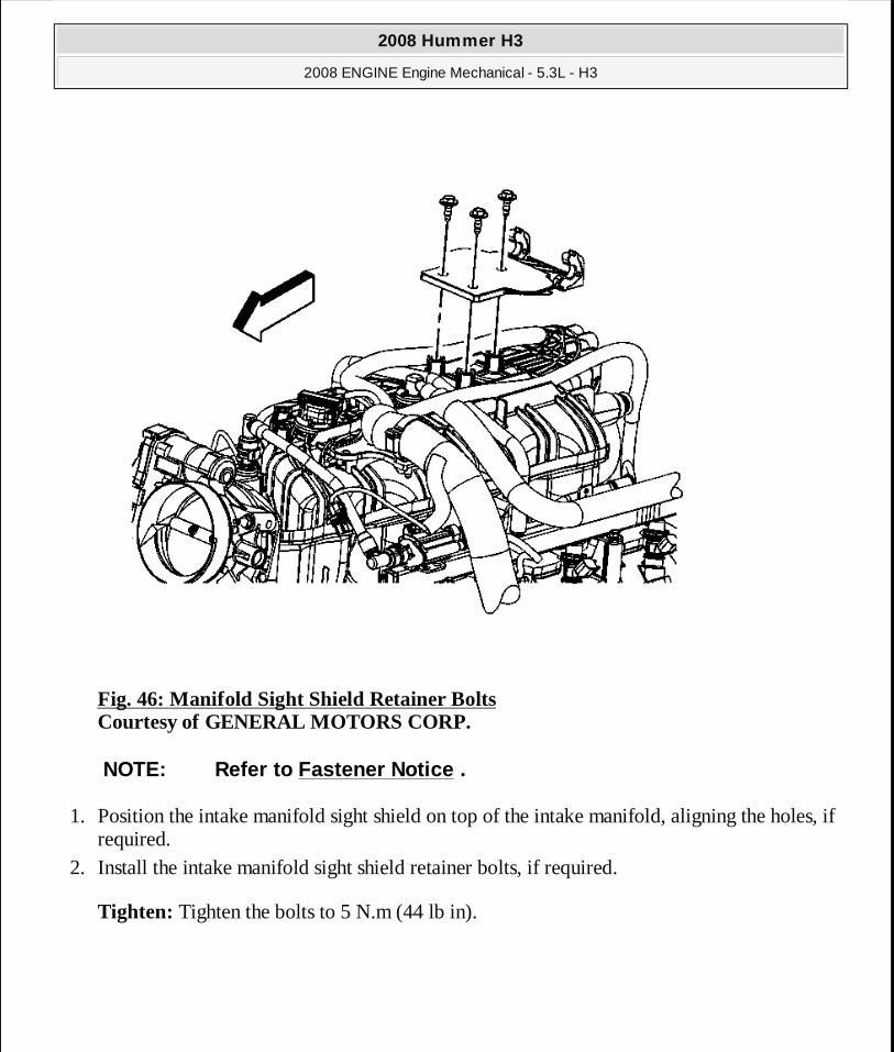
Fig. 46: Manifold Sight Shield Retainer Bolts Courtesy of GENERAL MOTORS CORP.
1. Position the intake manifold sight shield on top of the intake manifold, aligning the holes, if required.
2. Install the intake manifold sight shield retainer bolts, if required.
Tighten: Tighten the bolts to 5 N.m (44 lb in).
NOTE: Refer to Fastener Notice .
2008 Hummer H3
2008 ENGINE Engine Mechanical - 5.3L - H3
MY
Sunday, March 29, 2009 10:47:41 PM Page 100 © 2005 Mitchell Repair Information Company, LLC.
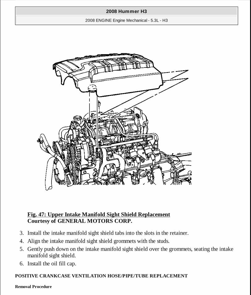
Fig. 47: Upper Intake Manifold Sight Shield Replacement Courtesy of GENERAL MOTORS CORP.
3. Install the intake manifold sight shield tabs into the slots in the retainer. 4. Align the intake manifold sight shield grommets with the studs. 5. Gently push down on the intake manifold sight shield over the grommets, seating the intake
manifold sight shield. 6. Install the oil fill cap.
POSITIVE CRANKCASE VENTILATION HOSE/PIPE/TUBE REPLACEMENT
Removal Procedure
2008 Hummer H3
2008 ENGINE Engine Mechanical - 5.3L - H3
MY
Sunday, March 29, 2009 10:47:41 PM Page 101 © 2005 Mitchell Repair Information Company, LLC.

Fig. 48: Positive Crankcase Ventilation Hose/Pipe/Tube Replacement Courtesy of GENERAL MOTORS CORP.
1. Remove the intake manifold sight shield. Refer to Upper Intake Manifold Sight Shield Replacement.
2. Remove the positive crankcase ventilation (PCV) hose from the intake manifold fitting and left valve rocker arm cover, if required.
2008 Hummer H3
2008 ENGINE Engine Mechanical - 5.3L - H3
MY
Sunday, March 29, 2009 10:47:41 PM Page 102 © 2005 Mitchell Repair Information Company, LLC.

Fig. 49: PCV Tube Courtesy of GENERAL MOTORS CORP.
3. Remove the PCV tube (1) from the air cleaner outlet duct, if required.
2008 Hummer H3
2008 ENGINE Engine Mechanical - 5.3L - H3
MY
Sunday, March 29, 2009 10:47:41 PM Page 103 © 2005 Mitchell Repair Information Company, LLC.
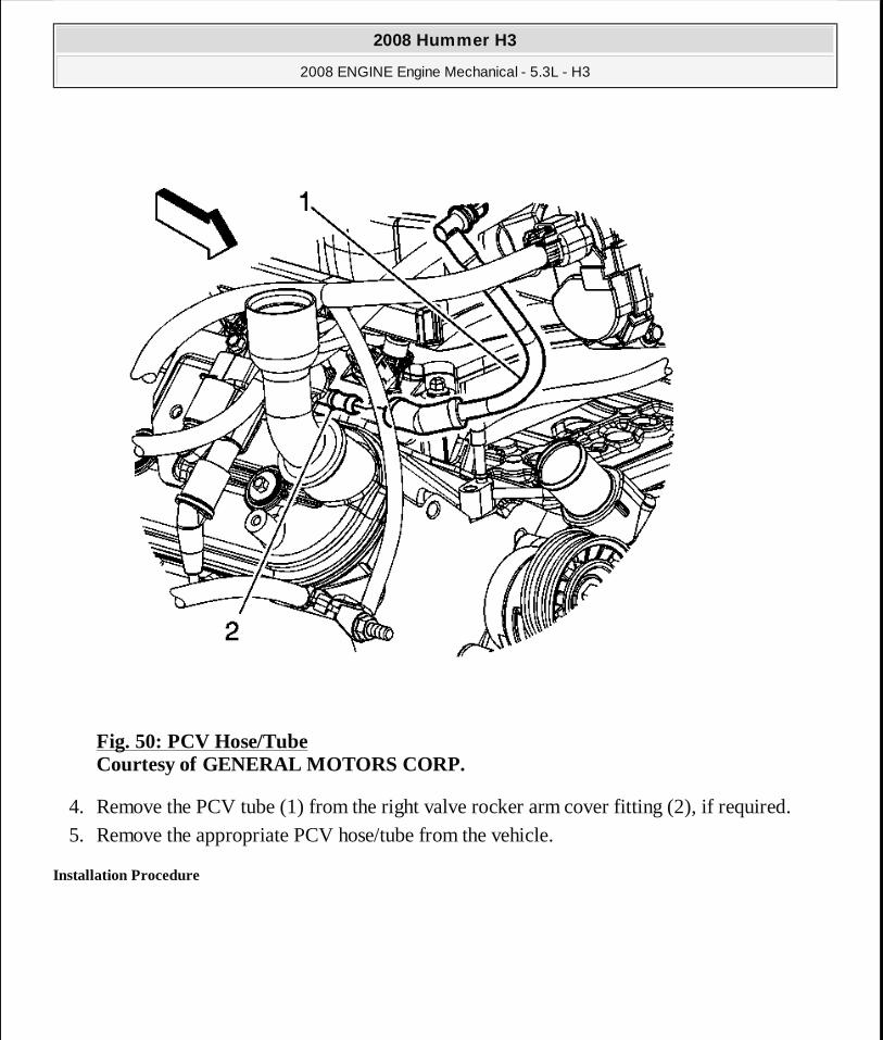
Fig. 50: PCV Hose/Tube Courtesy of GENERAL MOTORS CORP.
4. Remove the PCV tube (1) from the right valve rocker arm cover fitting (2), if required. 5. Remove the appropriate PCV hose/tube from the vehicle.
Installation Procedure
2008 Hummer H3
2008 ENGINE Engine Mechanical - 5.3L - H3
MY
Sunday, March 29, 2009 10:47:41 PM Page 104 © 2005 Mitchell Repair Information Company, LLC.
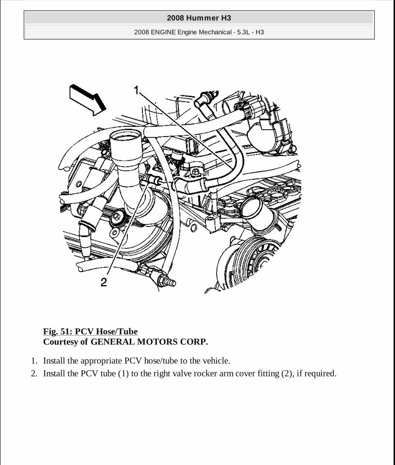
Fig. 51: PCV Hose/Tube Courtesy of GENERAL MOTORS CORP.
1. Install the appropriate PCV hose/tube to the vehicle. 2. Install the PCV tube (1) to the right valve rocker arm cover fitting (2), if required.
2008 Hummer H3
2008 ENGINE Engine Mechanical - 5.3L - H3
MY
Sunday, March 29, 2009 10:47:41 PM Page 105 © 2005 Mitchell Repair Information Company, LLC.

Fig. 52: PCV Tube Courtesy of GENERAL MOTORS CORP.
3. Install the PCV tube (1) to the air cleaner outlet duct, if required.
IMPORTANT: Route the PCV tube between the engine har ness and generator battery jumper cable.
2008 Hummer H3
2008 ENGINE Engine Mechanical - 5.3L - H3
MY
Sunday, March 29, 2009 10:47:41 PM Page 106 © 2005 Mitchell Repair Information Company, LLC.
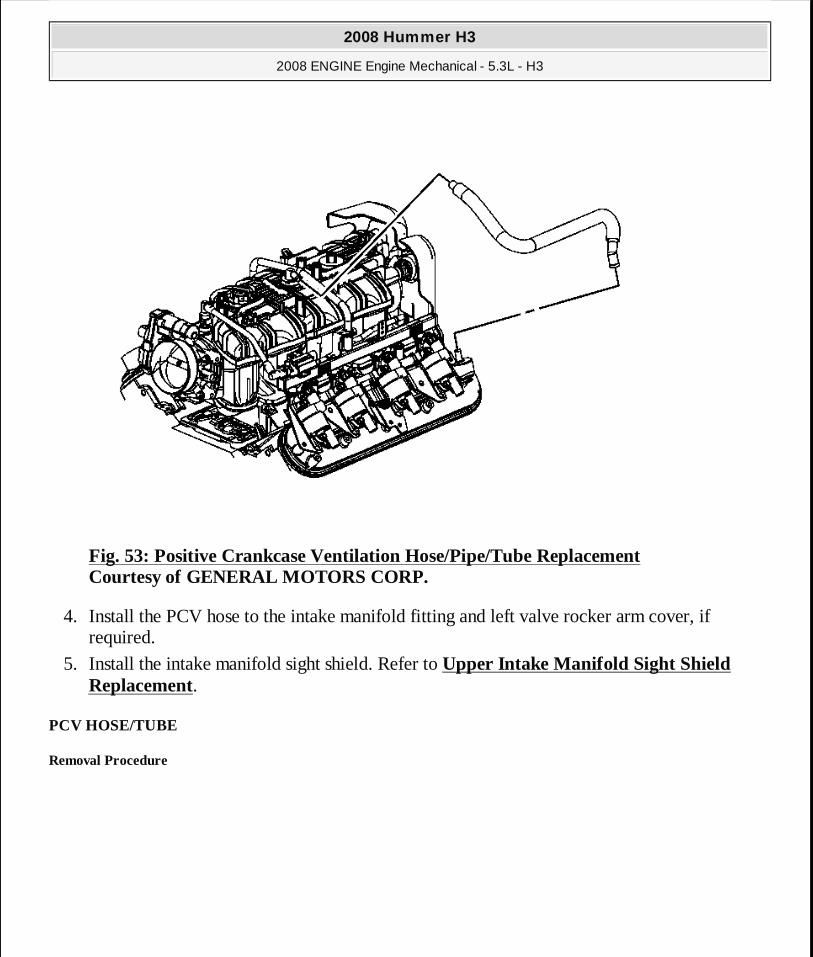
Fig. 53: Positive Crankcase Ventilation Hose/Pipe/Tube Replacement Courtesy of GENERAL MOTORS CORP.
4. Install the PCV hose to the intake manifold fitting and left valve rocker arm cover, if required.
5. Install the intake manifold sight shield. Refer to Upper Intake Manifold Sight Shield Replacement.
PCV HOSE/TUBE
Removal Procedure
2008 Hummer H3
2008 ENGINE Engine Mechanical - 5.3L - H3
MY
Sunday, March 29, 2009 10:47:41 PM Page 107 © 2005 Mitchell Repair Information Company, LLC.

Fig. 54: PCV Hose/Tube Courtesy of GENERAL MOTORS CORP.
1. Remove the air cleaner outlet duct. Refer to Air Cleaner Resonator Outlet Duct Replacement .
2. Remove the generator. Refer to Generator Replacement (LH8) . 3. Remove the engine harness retainer nut (1). 4. Remove the engine harness retainer from the stud and locator pin.
2008 Hummer H3
2008 ENGINE Engine Mechanical - 5.3L - H3
MY
Sunday, March 29, 2009 10:47:41 PM Page 108 © 2005 Mitchell Repair Information Company, LLC.
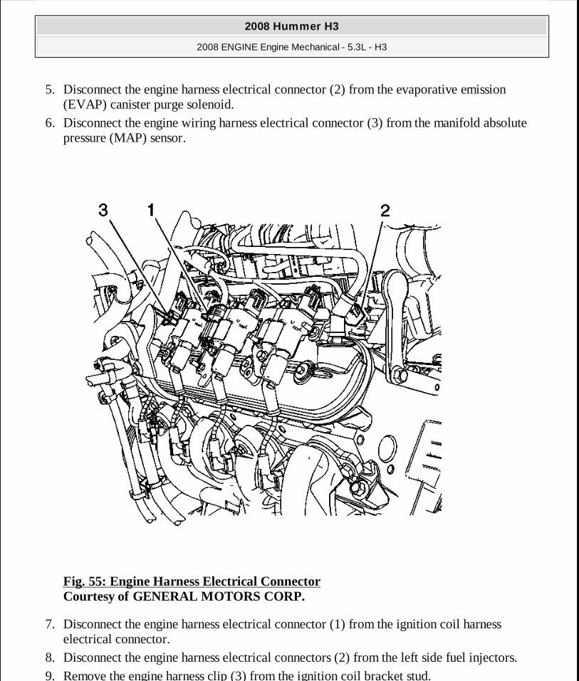
5. Disconnect the engine harness electrical connector (2) from the evaporative emission (EVAP) canister purge solenoid.
6. Disconnect the engine wiring harness electrical connector (3) from the manifold absolute pressure (MAP) sensor.
Fig. 55: Engine Harness Electrical Connector Courtesy of GENERAL MOTORS CORP.
7. Disconnect the engine harness electrical connector (1) from the ignition coil harness electrical connector.
8. Disconnect the engine harness electrical connectors (2) from the left side fuel injectors. 9. Remove the engine harness clip (3) from the ignition coil bracket stud.
2008 Hummer H3
2008 ENGINE Engine Mechanical - 5.3L - H3
MY
Sunday, March 29, 2009 10:47:41 PM Page 109 © 2005 Mitchell Repair Information Company, LLC.

Fig. 56: Engine Harness Electrical Connector & Ignition Coil Harness Electrical Connector Courtesy of GENERAL MOTORS CORP.
10. Disconnect the engine harness electrical connector (1) from the ignition coil harness electrical connector.
11. Disconnect the engine harness electrical connector (2) from the throttle actuator. 12. Remove the engine harness clip (3) from the ignition coil bracket stud. 13. Disconnect the engine harness electrical connectors (4) from the right side fuel injectors.
2008 Hummer H3
2008 ENGINE Engine Mechanical - 5.3L - H3
MY
Sunday, March 29, 2009 10:47:41 PM Page 110 © 2005 Mitchell Repair Information Company, LLC.
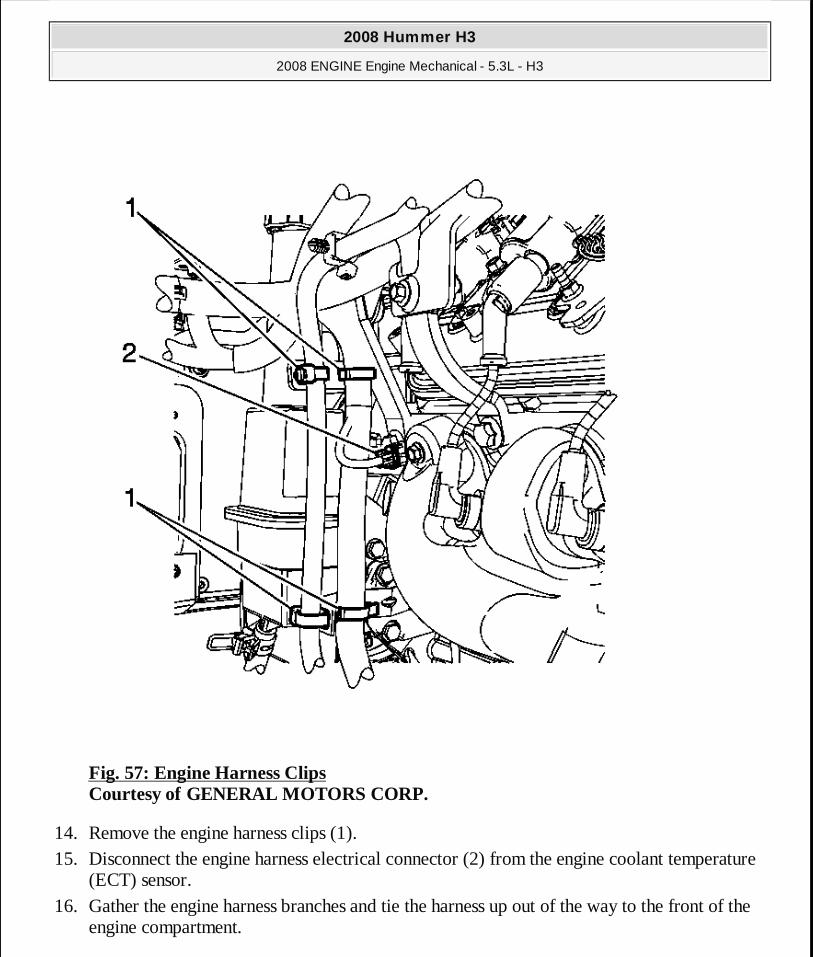
Fig. 57: Engine Harness Clips Courtesy of GENERAL MOTORS CORP.
14. Remove the engine harness clips (1). 15. Disconnect the engine harness electrical connector (2) from the engine coolant temperature
(ECT) sensor. 16. Gather the engine harness branches and tie the harness up out of the way to the front of the
engine compartment.
2008 Hummer H3
2008 ENGINE Engine Mechanical - 5.3L - H3
MY
Sunday, March 29, 2009 10:47:41 PM Page 111 © 2005 Mitchell Repair Information Company, LLC.
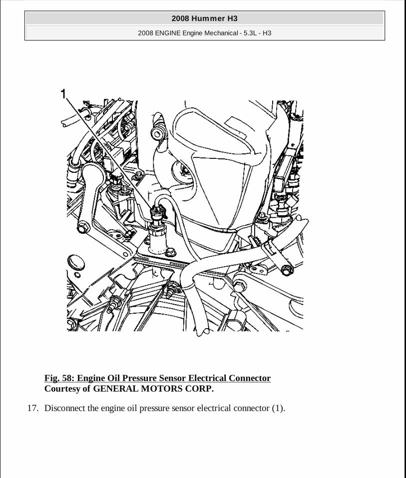
Fig. 58: Engine Oil Pressure Sensor Electrical Connector Courtesy of GENERAL MOTORS CORP.
17. Disconnect the engine oil pressure sensor electrical connector (1).
2008 Hummer H3
2008 ENGINE Engine Mechanical - 5.3L - H3
MY
Sunday, March 29, 2009 10:47:41 PM Page 112 © 2005 Mitchell Repair Information Company, LLC.

Fig. 59: Brake Booster Vacuum Hose Courtesy of GENERAL MOTORS CORP.
18. Reposition the brake booster vacuum hose clamp at the booster. 19. Remove the brake booster vacuum hose from the booster fitting. 20. Secure the brake booster vacuum hose to the intake manifold.
2008 Hummer H3
2008 ENGINE Engine Mechanical - 5.3L - H3
MY
Sunday, March 29, 2009 10:47:41 PM Page 113 © 2005 Mitchell Repair Information Company, LLC.
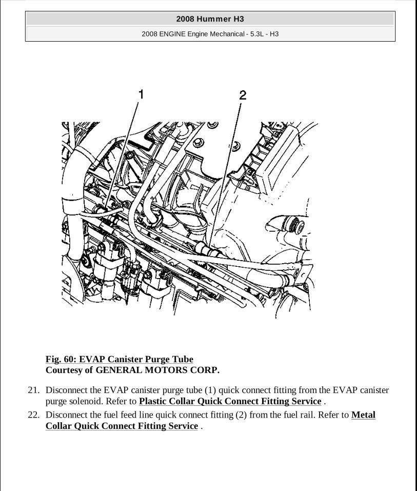
Fig. 60: EVAP Canister Purge Tube Courtesy of GENERAL MOTORS CORP.
21. Disconnect the EVAP canister purge tube (1) quick connect fitting from the EVAP canister purge solenoid. Refer to Plastic Collar Quick Connect Fitting Service .
22. Disconnect the fuel feed line quick connect fitting (2) from the fuel rail. Refer to Metal Collar Quick Connect Fitting Service .
2008 Hummer H3
2008 ENGINE Engine Mechanical - 5.3L - H3
MY
Sunday, March 29, 2009 10:47:41 PM Page 114 © 2005 Mitchell Repair Information Company, LLC.

Fig. 61: Positive Crankcase Ventilation Hose/Pipe/Tube Replacement Courtesy of GENERAL MOTORS CORP.
23. Remove the positive crankcase ventilation (PCV) hose from the intake manifold fitting. 24. Position the hose out of the way.
2008 Hummer H3
2008 ENGINE Engine Mechanical - 5.3L - H3
MY
Sunday, March 29, 2009 10:47:41 PM Page 115 © 2005 Mitchell Repair Information Company, LLC.
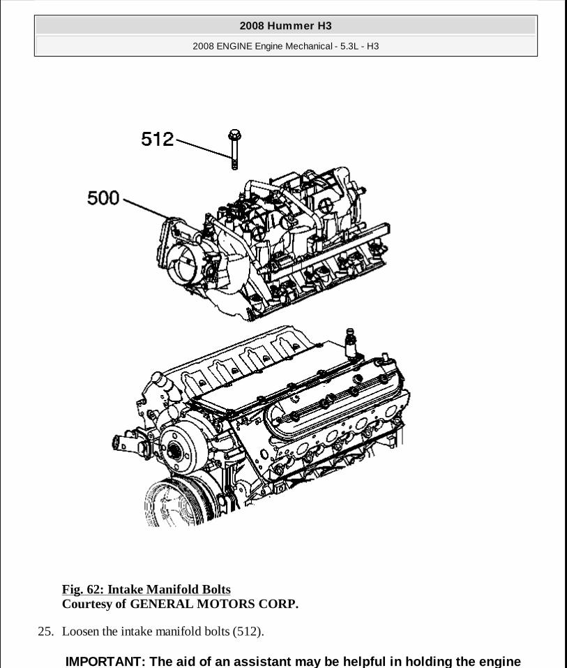
Fig. 62: Intake Manifold Bolts Courtesy of GENERAL MOTORS CORP.
25. Loosen the intake manifold bolts (512).
IMPORTANT: The aid of an assistant may be helpful in holding the engine
2008 Hummer H3
2008 ENGINE Engine Mechanical - 5.3L - H3
MY
Sunday, March 29, 2009 10:47:41 PM Page 116 © 2005 Mitchell Repair Information Company, LLC.
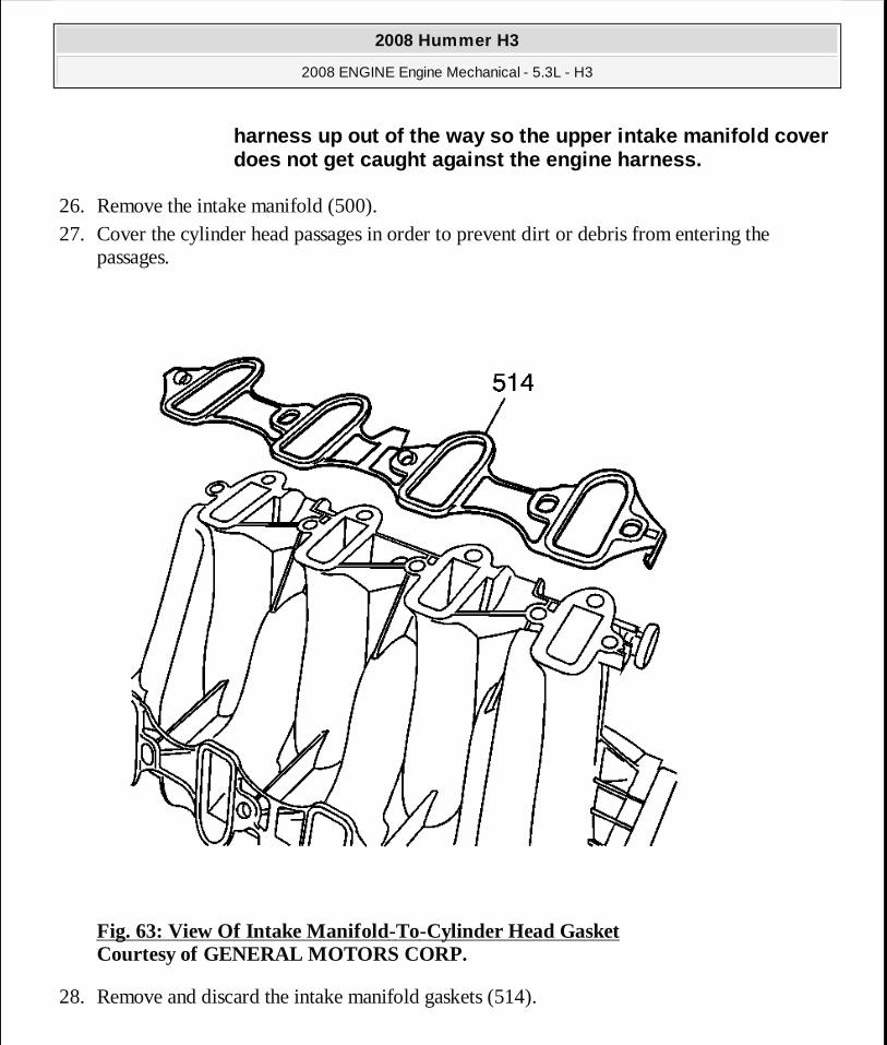
26. Remove the intake manifold (500). 27. Cover the cylinder head passages in order to prevent dirt or debris from entering the
passages.
Fig. 63: View Of Intake Manifold-To-Cylinder Head Gasket Courtesy of GENERAL MOTORS CORP.
28. Remove and discard the intake manifold gaskets (514).
harness up out of the way so the upper intake manif old cover does not get caught against the engine harness.
2008 Hummer H3
2008 ENGINE Engine Mechanical - 5.3L - H3
MY
Sunday, March 29, 2009 10:47:41 PM Page 117 © 2005 Mitchell Repair Information Company, LLC.
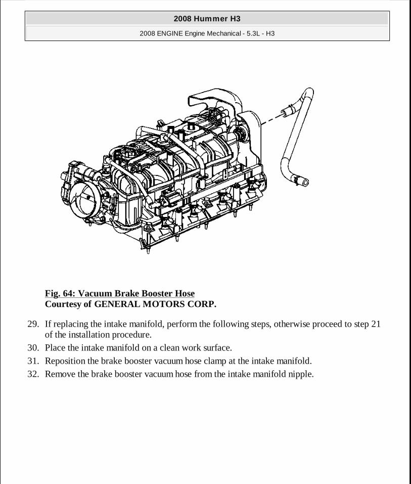
Fig. 64: Vacuum Brake Booster Hose Courtesy of GENERAL MOTORS CORP.
29. If replacing the intake manifold, perform the following steps, otherwise proceed to step 21 of the installation procedure.
30. Place the intake manifold on a clean work surface. 31. Reposition the brake booster vacuum hose clamp at the intake manifold. 32. Remove the brake booster vacuum hose from the intake manifold nipple.
2008 Hummer H3
2008 ENGINE Engine Mechanical - 5.3L - H3
MY
Sunday, March 29, 2009 10:47:41 PM Page 118 © 2005 Mitchell Repair Information Company, LLC.
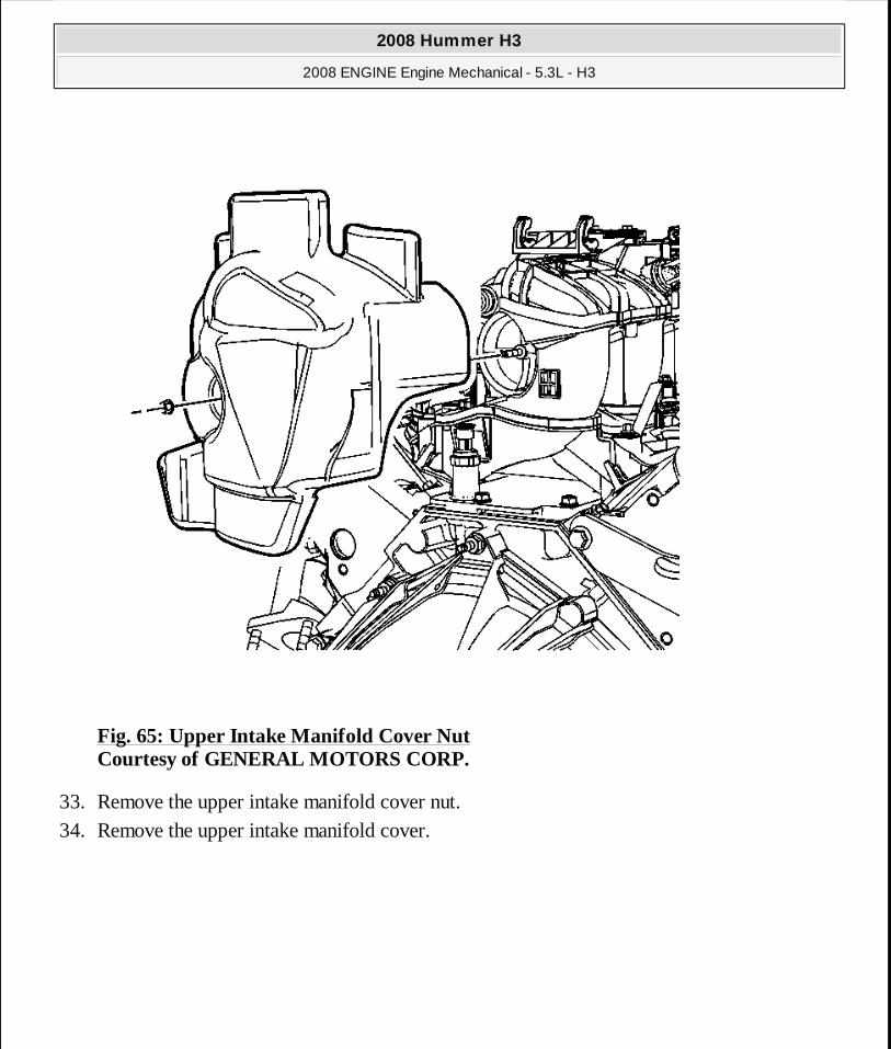
Fig. 65: Upper Intake Manifold Cover Nut Courtesy of GENERAL MOTORS CORP.
33. Remove the upper intake manifold cover nut. 34. Remove the upper intake manifold cover.
2008 Hummer H3
2008 ENGINE Engine Mechanical - 5.3L - H3
MY
Sunday, March 29, 2009 10:47:41 PM Page 119 © 2005 Mitchell Repair Information Company, LLC.
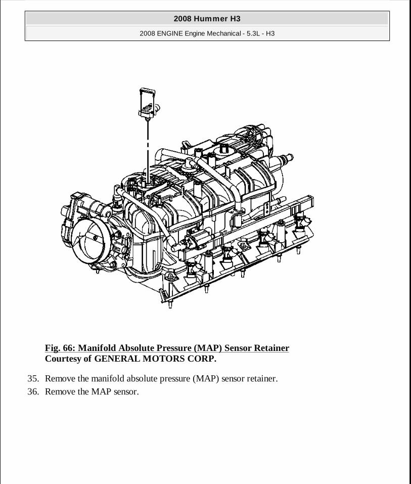
Fig. 66: Manifold Absolute Pressure (MAP) Sensor Retainer Courtesy of GENERAL MOTORS CORP.
35. Remove the manifold absolute pressure (MAP) sensor retainer. 36. Remove the MAP sensor.
2008 Hummer H3
2008 ENGINE Engine Mechanical - 5.3L - H3
MY
Sunday, March 29, 2009 10:47:41 PM Page 120 © 2005 Mitchell Repair Information Company, LLC.
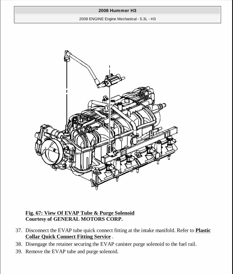
Fig. 67: View Of EVAP Tube & Purge Solenoid Courtesy of GENERAL MOTORS CORP.
37. Disconnect the EVAP tube quick connect fitting at the intake manifold. Refer to Plastic Collar Quick Connect Fitting Service .
38. Disengage the retainer securing the EVAP canister purge solenoid to the fuel rail. 39. Remove the EVAP tube and purge solenoid.
2008 Hummer H3
2008 ENGINE Engine Mechanical - 5.3L - H3
MY
Sunday, March 29, 2009 10:47:41 PM Page 121 © 2005 Mitchell Repair Information Company, LLC.
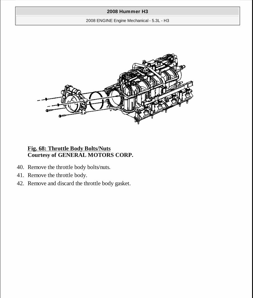
Fig. 68: Throttle Body Bolts/Nuts Courtesy of GENERAL MOTORS CORP.
40. Remove the throttle body bolts/nuts. 41. Remove the throttle body. 42. Remove and discard the throttle body gasket.
2008 Hummer H3
2008 ENGINE Engine Mechanical - 5.3L - H3
MY
Sunday, March 29, 2009 10:47:42 PM Page 122 © 2005 Mitchell Repair Information Company, LLC.
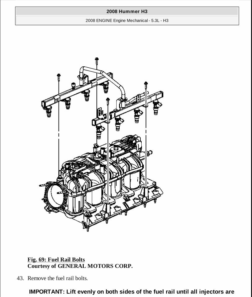
Fig. 69: Fuel Rail Bolts Courtesy of GENERAL MOTORS CORP.
43. Remove the fuel rail bolts.
IMPORTANT: Lift evenly on both sides of the fuel rai l until all injectors are
2008 Hummer H3
2008 ENGINE Engine Mechanical - 5.3L - H3
MY
Sunday, March 29, 2009 10:47:42 PM Page 123 © 2005 Mitchell Repair Information Company, LLC.
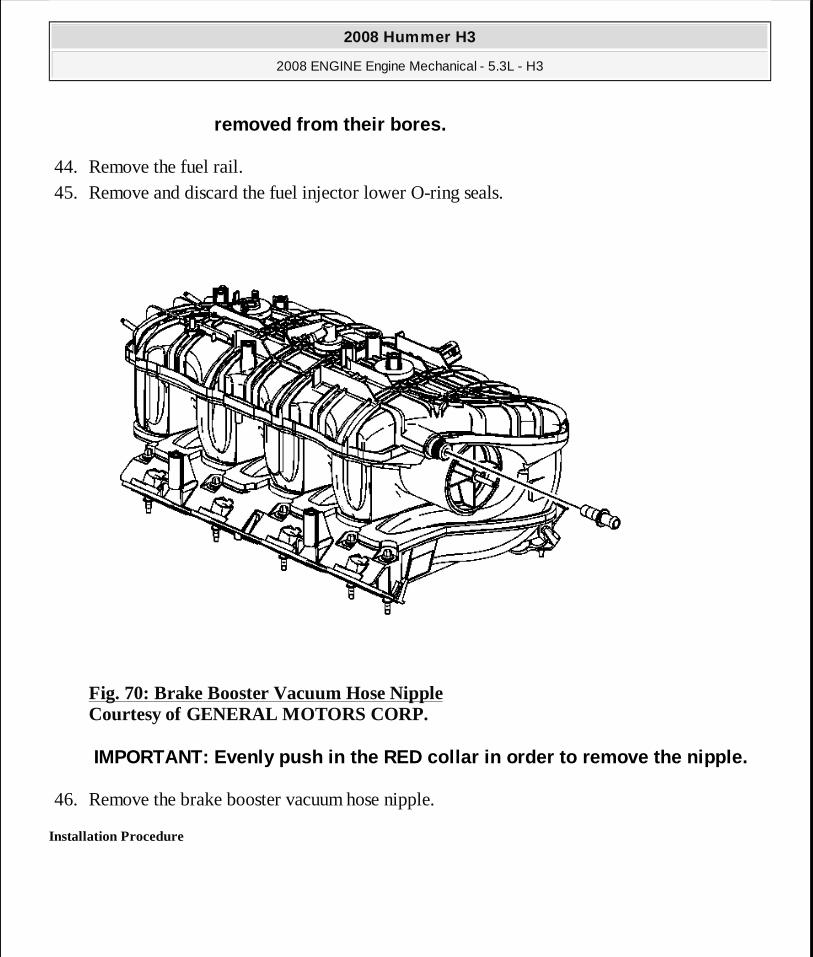
44. Remove the fuel rail. 45. Remove and discard the fuel injector lower O-ring seals.
Fig. 70: Brake Booster Vacuum Hose Nipple Courtesy of GENERAL MOTORS CORP.
46. Remove the brake booster vacuum hose nipple.
Installation Procedure
removed from their bores.
IMPORTANT: Evenly push in the RED collar in order to remove the nipple.
2008 Hummer H3
2008 ENGINE Engine Mechanical - 5.3L - H3
MY
Sunday, March 29, 2009 10:47:42 PM Page 124 © 2005 Mitchell Repair Information Company, LLC.
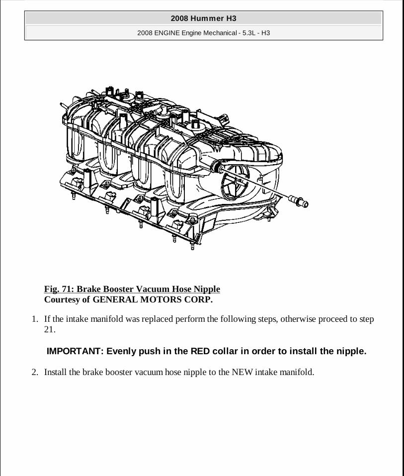
Fig. 71: Brake Booster Vacuum Hose Nipple Courtesy of GENERAL MOTORS CORP.
1. If the intake manifold was replaced perform the following steps, otherwise proceed to step 21.
2. Install the brake booster vacuum hose nipple to the NEW intake manifold.
IMPORTANT: Evenly push in the RED collar in order to install the nipple.
2008 Hummer H3
2008 ENGINE Engine Mechanical - 5.3L - H3
MY
Sunday, March 29, 2009 10:47:42 PM Page 125 © 2005 Mitchell Repair Information Company, LLC.
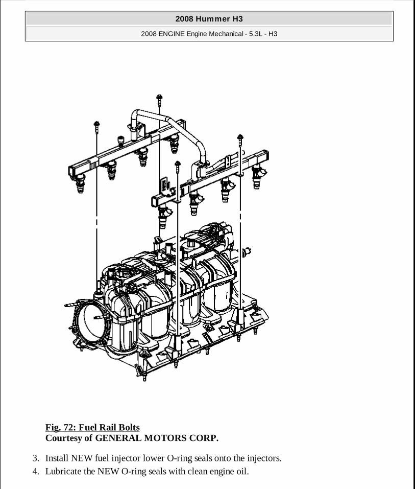
Fig. 72: Fuel Rail Bolts Courtesy of GENERAL MOTORS CORP.
3. Install NEW fuel injector lower O-ring seals onto the injectors. 4. Lubricate the NEW O-ring seals with clean engine oil.
2008 Hummer H3
2008 ENGINE Engine Mechanical - 5.3L - H3
MY
Sunday, March 29, 2009 10:47:42 PM Page 126 © 2005 Mitchell Repair Information Company, LLC.

5. Install the fuel rail.
6. Install the fuel rail bolts.
Tighten: Tighten the bolts to 10 N.m (89 lb in).
Fig. 73: Throttle Body Bolts/Nuts Courtesy of GENERAL MOTORS CORP.
7. Install a NEW throttle body gasket to the intake manifold. 8. Install the throttle body. 9. Install the throttle body bolts/nuts.
Tighten: Tighten the bolts/nuts to 10 N.m (89 lb in).
IMPORTANT: Push down firmly on both sides of the rai l until all the injectors have been seated into their bores.
NOTE: Refer to Fastener Notice .
2008 Hummer H3
2008 ENGINE Engine Mechanical - 5.3L - H3
MY
Sunday, March 29, 2009 10:47:42 PM Page 127 © 2005 Mitchell Repair Information Company, LLC.

Fig. 74: View Of EVAP Tube & Purge Solenoid Courtesy of GENERAL MOTORS CORP.
10. Install the EVAP tube and purge solenoid. 11. Install the EVAP canister purge solenoid to the fuel rail bracket and engage the retainer.
12. Connect the EVAP tube quick connect fitting at the intake manifold. Refer to Plastic Collar Quick Connect Fitting Service .
2008 Hummer H3
2008 ENGINE Engine Mechanical - 5.3L - H3
MY
Sunday, March 29, 2009 10:47:42 PM Page 128 © 2005 Mitchell Repair Information Company, LLC.
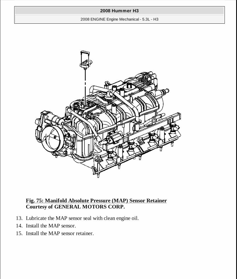
Fig. 75: Manifold Absolute Pressure (MAP) Sensor Retainer Courtesy of GENERAL MOTORS CORP.
13. Lubricate the MAP sensor seal with clean engine oil. 14. Install the MAP sensor. 15. Install the MAP sensor retainer.
2008 Hummer H3
2008 ENGINE Engine Mechanical - 5.3L - H3
MY
Sunday, March 29, 2009 10:47:42 PM Page 129 © 2005 Mitchell Repair Information Company, LLC.
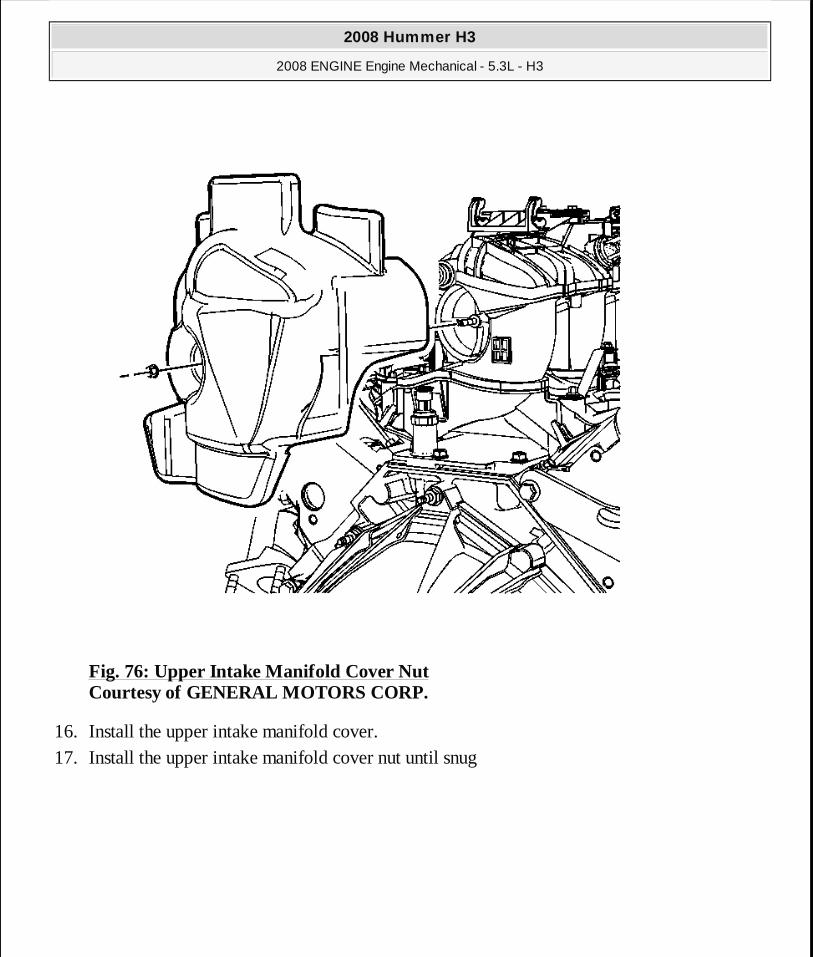
Fig. 76: Upper Intake Manifold Cover Nut Courtesy of GENERAL MOTORS CORP.
16. Install the upper intake manifold cover. 17. Install the upper intake manifold cover nut until snug
2008 Hummer H3
2008 ENGINE Engine Mechanical - 5.3L - H3
MY
Sunday, March 29, 2009 10:47:42 PM Page 130 © 2005 Mitchell Repair Information Company, LLC.
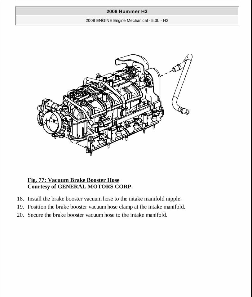
Fig. 77: Vacuum Brake Booster Hose Courtesy of GENERAL MOTORS CORP.
18. Install the brake booster vacuum hose to the intake manifold nipple. 19. Position the brake booster vacuum hose clamp at the intake manifold. 20. Secure the brake booster vacuum hose to the intake manifold.
2008 Hummer H3
2008 ENGINE Engine Mechanical - 5.3L - H3
MY
Sunday, March 29, 2009 10:47:42 PM Page 131 © 2005 Mitchell Repair Information Company, LLC.
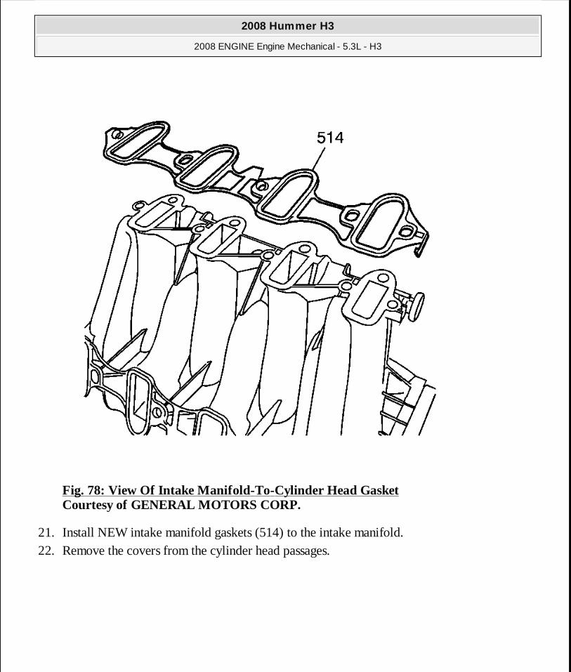
Fig. 78: View Of Intake Manifold-To-Cylinder Head Gasket Courtesy of GENERAL MOTORS CORP.
21. Install NEW intake manifold gaskets (514) to the intake manifold. 22. Remove the covers from the cylinder head passages.
2008 Hummer H3
2008 ENGINE Engine Mechanical - 5.3L - H3
MY
Sunday, March 29, 2009 10:47:42 PM Page 132 © 2005 Mitchell Repair Information Company, LLC.

Fig. 79: Intake Manifold Bolts Courtesy of GENERAL MOTORS CORP.
23. Install the intake manifold (500).
IMPORTANT: The aid of an assistant may be helpful in holding the engine
2008 Hummer H3
2008 ENGINE Engine Mechanical - 5.3L - H3
MY
Sunday, March 29, 2009 10:47:42 PM Page 133 © 2005 Mitchell Repair Information Company, LLC.

24. Tighten the intake manifold bolts (512) until snug.
Fig. 80: Intake Manifold Bolt Tightening Sequence Courtesy of GENERAL MOTORS CORP.
25. Tighten the intake manifold bolts to specifications.
Tighten: � Tighten the bolts a first pass in the sequence shown to 5 N.m (44 lb in). � Tighten the bolts a final pass in the sequence shown to 10 N.m (89 lb in).
harness up out of the way so the upper intake manif old cover does not get caught against the engine harness.
2008 Hummer H3
2008 ENGINE Engine Mechanical - 5.3L - H3
MY
Sunday, March 29, 2009 10:47:42 PM Page 134 © 2005 Mitchell Repair Information Company, LLC.

Fig. 81: Positive Crankcase Ventilation Hose/Pipe/Tube Replacement Courtesy of GENERAL MOTORS CORP.
26. Position and install the PCV hose to the intake manifold fitting.
2008 Hummer H3
2008 ENGINE Engine Mechanical - 5.3L - H3
MY
Sunday, March 29, 2009 10:47:42 PM Page 135 © 2005 Mitchell Repair Information Company, LLC.
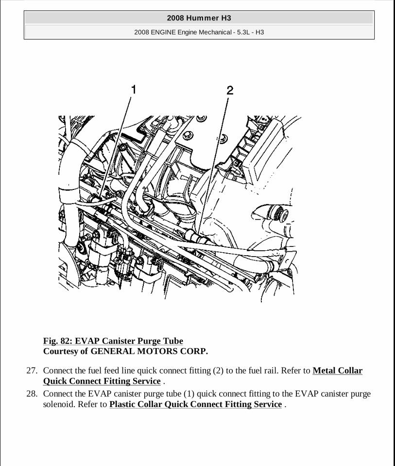
Fig. 82: EVAP Canister Purge Tube Courtesy of GENERAL MOTORS CORP.
27. Connect the fuel feed line quick connect fitting (2) to the fuel rail. Refer to Metal Collar Quick Connect Fitting Service .
28. Connect the EVAP canister purge tube (1) quick connect fitting to the EVAP canister purge solenoid. Refer to Plastic Collar Quick Connect Fitting Service .
2008 Hummer H3
2008 ENGINE Engine Mechanical - 5.3L - H3
MY
Sunday, March 29, 2009 10:47:42 PM Page 136 © 2005 Mitchell Repair Information Company, LLC.
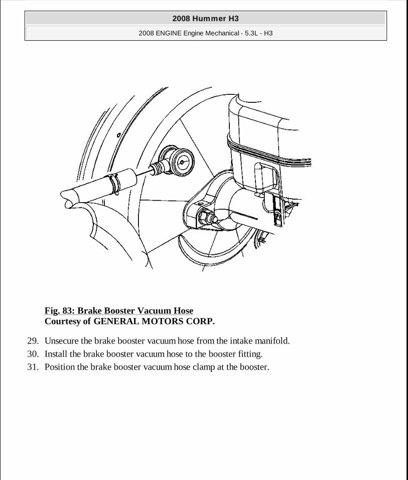
Fig. 83: Brake Booster Vacuum Hose Courtesy of GENERAL MOTORS CORP.
29. Unsecure the brake booster vacuum hose from the intake manifold. 30. Install the brake booster vacuum hose to the booster fitting. 31. Position the brake booster vacuum hose clamp at the booster.
2008 Hummer H3
2008 ENGINE Engine Mechanical - 5.3L - H3
MY
Sunday, March 29, 2009 10:47:42 PM Page 137 © 2005 Mitchell Repair Information Company, LLC.

Fig. 84: Engine Oil Pressure Sensor Electrical Connector Courtesy of GENERAL MOTORS CORP.
32. Connect the engine oil pressure sensor electrical connector (1).
2008 Hummer H3
2008 ENGINE Engine Mechanical - 5.3L - H3
MY
Sunday, March 29, 2009 10:47:42 PM Page 138 © 2005 Mitchell Repair Information Company, LLC.
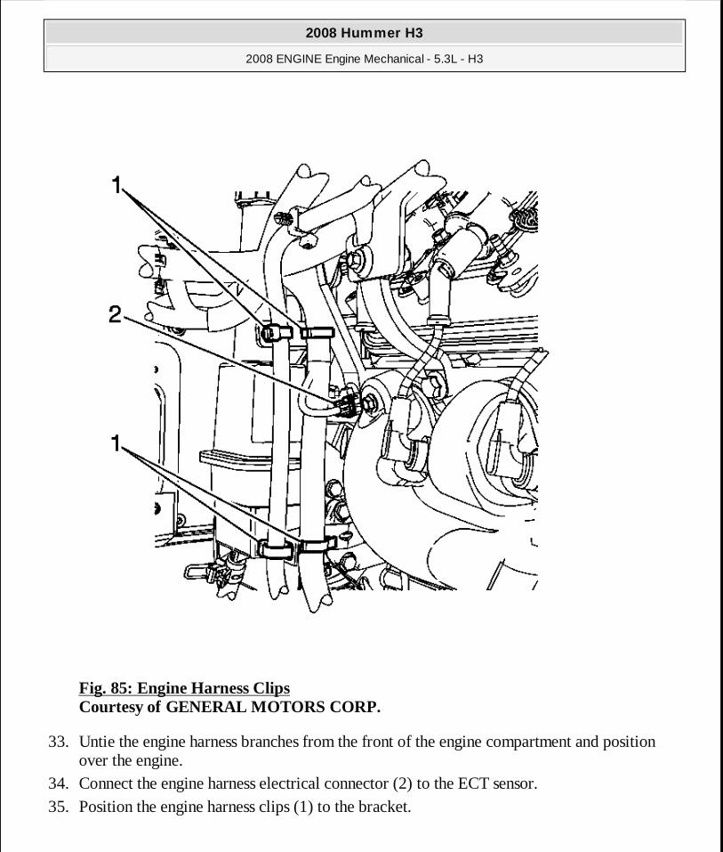
Fig. 85: Engine Harness Clips Courtesy of GENERAL MOTORS CORP.
33. Untie the engine harness branches from the front of the engine compartment and position over the engine.
34. Connect the engine harness electrical connector (2) to the ECT sensor. 35. Position the engine harness clips (1) to the bracket.
2008 Hummer H3
2008 ENGINE Engine Mechanical - 5.3L - H3
MY
Sunday, March 29, 2009 10:47:42 PM Page 139 © 2005 Mitchell Repair Information Company, LLC.
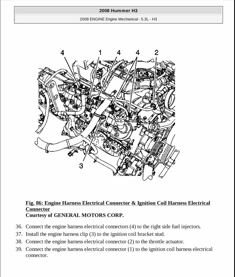
Fig. 86: Engine Harness Electrical Connector & Ignition Coil Harness Electrical Connector Courtesy of GENERAL MOTORS CORP.
36. Connect the engine harness electrical connectors (4) to the right side fuel injectors. 37. Install the engine harness clip (3) to the ignition coil bracket stud. 38. Connect the engine harness electrical connector (2) to the throttle actuator. 39. Connect the engine harness electrical connector (1) to the ignition coil harness electrical
connector.
2008 Hummer H3
2008 ENGINE Engine Mechanical - 5.3L - H3
MY
Sunday, March 29, 2009 10:47:42 PM Page 140 © 2005 Mitchell Repair Information Company, LLC.
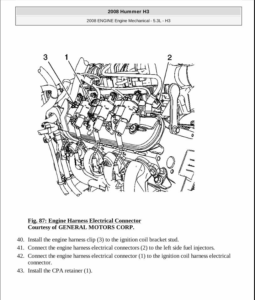
Fig. 87: Engine Harness Electrical Connector Courtesy of GENERAL MOTORS CORP.
40. Install the engine harness clip (3) to the ignition coil bracket stud. 41. Connect the engine harness electrical connectors (2) to the left side fuel injectors. 42. Connect the engine harness electrical connector (1) to the ignition coil harness electrical
connector. 43. Install the CPA retainer (1).
2008 Hummer H3
2008 ENGINE Engine Mechanical - 5.3L - H3
MY
Sunday, March 29, 2009 10:47:42 PM Page 141 © 2005 Mitchell Repair Information Company, LLC.

Fig. 88: PCV Hose/Tube Courtesy of GENERAL MOTORS CORP.
44. Connect the engine wiring harness electrical connector (3) to the MAP sensor. 45. Connect the engine harness electrical connector (2) to the EVAP canister purge solenoid. 46. Install the engine harness retainer to the stud and locator pin. 47. Install the engine harness retainer nut (1).
2008 Hummer H3
2008 ENGINE Engine Mechanical - 5.3L - H3
MY
Sunday, March 29, 2009 10:47:42 PM Page 142 © 2005 Mitchell Repair Information Company, LLC.
Tighten: Tighten the nut to 5 N.m (44 lb in).
48. Install the generator. Refer to Generator Replacement (LH8) . 49. Install the air cleaner outlet duct. Refer to Air Cleaner Resonator Outlet Duct
Replacement .
ENGINE BLOCK VALLEY COVER REPLACEMENT
Removal Procedure
2008 Hummer H3
2008 ENGINE Engine Mechanical - 5.3L - H3
MY
Sunday, March 29, 2009 10:47:42 PM Page 143 © 2005 Mitchell Repair Information Company, LLC.
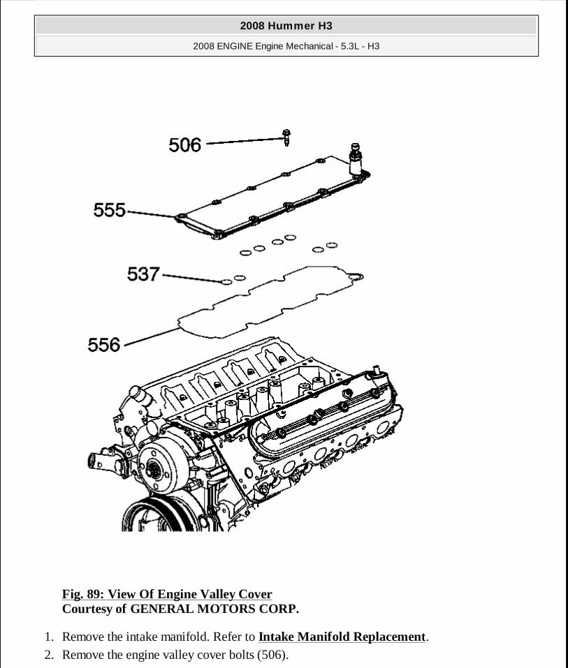
Fig. 89: View Of Engine Valley Cover Courtesy of GENERAL MOTORS CORP.
1. Remove the intake manifold. Refer to Intake Manifold Replacement. 2. Remove the engine valley cover bolts (506).
2008 Hummer H3
2008 ENGINE Engine Mechanical - 5.3L - H3
MY
Sunday, March 29, 2009 10:47:42 PM Page 144 © 2005 Mitchell Repair Information Company, LLC.
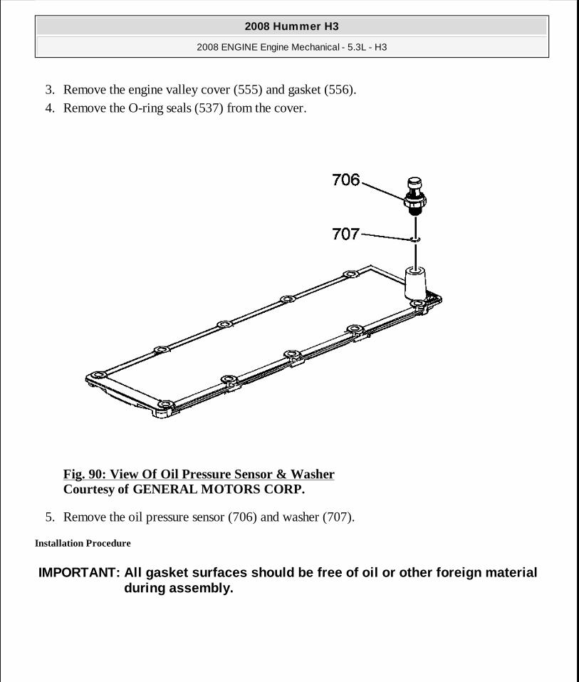
3. Remove the engine valley cover (555) and gasket (556). 4. Remove the O-ring seals (537) from the cover.
Fig. 90: View Of Oil Pressure Sensor & Washer Courtesy of GENERAL MOTORS CORP.
5. Remove the oil pressure sensor (706) and washer (707).
Installation Procedure
IMPORTANT: All gasket surfaces should be free of oil or other foreign material during assembly.
2008 Hummer H3
2008 ENGINE Engine Mechanical - 5.3L - H3
MY
Sunday, March 29, 2009 10:47:42 PM Page 145 © 2005 Mitchell Repair Information Company, LLC.
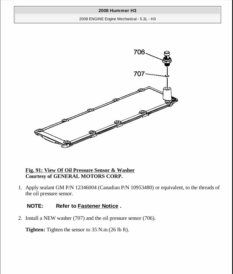
Fig. 91: View Of Oil Pressure Sensor & Washer Courtesy of GENERAL MOTORS CORP.
1. Apply sealant GM P/N 12346004 (Canadian P/N 10953480) or equivalent, to the threads of the oil pressure sensor.
2. Install a NEW washer (707) and the oil pressure sensor (706).
Tighten: Tighten the sensor to 35 N.m (26 lb ft).
NOTE: Refer to Fastener Notice .
2008 Hummer H3
2008 ENGINE Engine Mechanical - 5.3L - H3
MY
Sunday, March 29, 2009 10:47:42 PM Page 146 © 2005 Mitchell Repair Information Company, LLC.
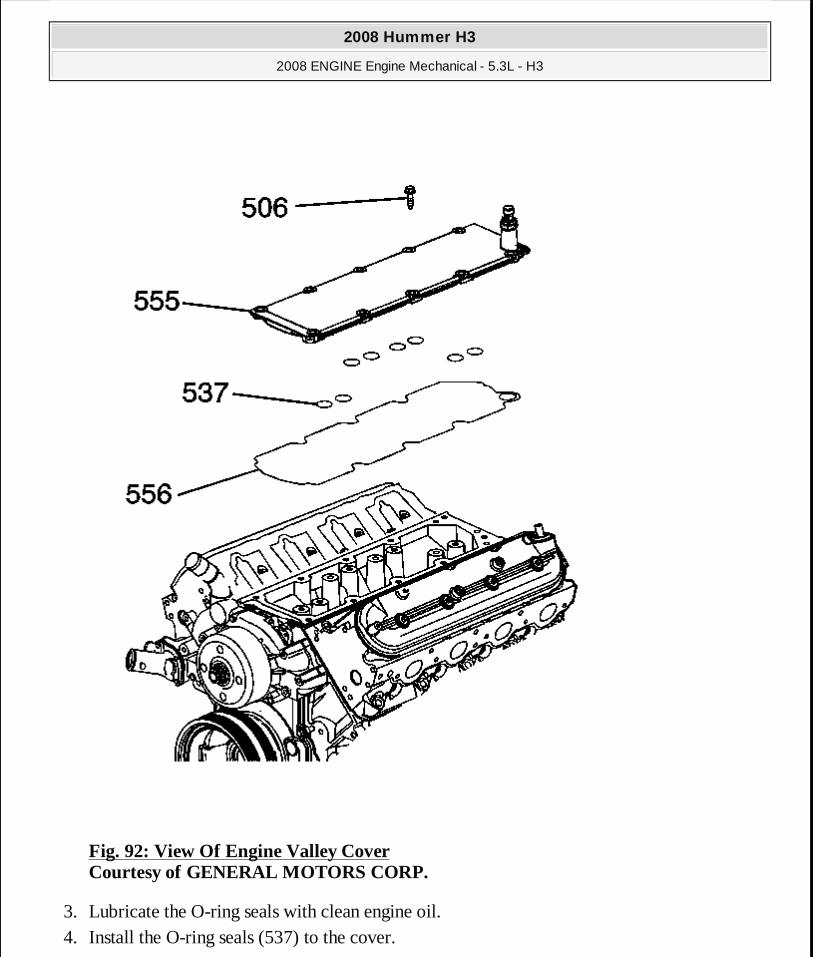
Fig. 92: View Of Engine Valley Cover Courtesy of GENERAL MOTORS CORP.
3. Lubricate the O-ring seals with clean engine oil. 4. Install the O-ring seals (537) to the cover.
2008 Hummer H3
2008 ENGINE Engine Mechanical - 5.3L - H3
MY
Sunday, March 29, 2009 10:47:42 PM Page 147 © 2005 Mitchell Repair Information Company, LLC.

5. Set the engine valley cover (555) onto the engine. 6. Install the engine valley cover bolts (506).
Tighten: Tighten the bolts to 25 N.m (18 lb ft).
7. Install the intake manifold. Refer to Intake Manifold Replacement.
VALVE ROCKER ARM COVER REPLACEMENT - LEFT SIDE
Removal Procedure
Fig. 93: Valve Rocker Arm Cover Replacement - Left Side Courtesy of GENERAL MOTORS CORP.
2008 Hummer H3
2008 ENGINE Engine Mechanical - 5.3L - H3
MY
Sunday, March 29, 2009 10:47:42 PM Page 148 © 2005 Mitchell Repair Information Company, LLC.
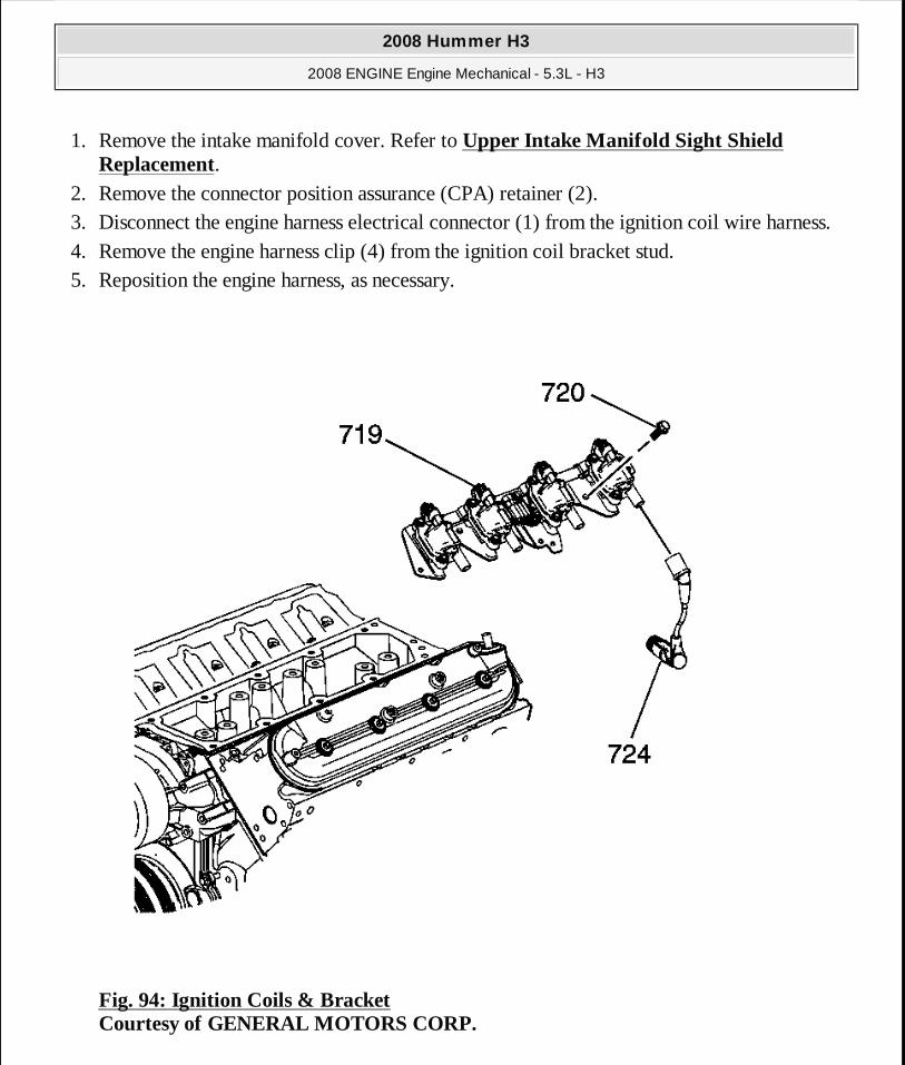
1. Remove the intake manifold cover. Refer to Upper Intake Manifold Sight Shield Replacement.
2. Remove the connector position assurance (CPA) retainer (2). 3. Disconnect the engine harness electrical connector (1) from the ignition coil wire harness. 4. Remove the engine harness clip (4) from the ignition coil bracket stud. 5. Reposition the engine harness, as necessary.
Fig. 94: Ignition Coils & Bracket Courtesy of GENERAL MOTORS CORP.
2008 Hummer H3
2008 ENGINE Engine Mechanical - 5.3L - H3
MY
Sunday, March 29, 2009 10:47:42 PM Page 149 © 2005 Mitchell Repair Information Company, LLC.

6. Remove the spark plug wires (724) from the ignition coils. � Twist each plug wire 1/2 turn. � Pull only on the boot in order to remove the wire from the ignition coil.
7. Remove the ignition coil bracket studs (720). 8. Remove the ignition coil bracket (719).
Fig. 95: Positive Crankcase Ventilation Hose/Pipe/Tube Replacement Courtesy of GENERAL MOTORS CORP.
9. Remove the positive crankcase ventilation (PCV) hose.
2008 Hummer H3
2008 ENGINE Engine Mechanical - 5.3L - H3
MY
Sunday, March 29, 2009 10:47:43 PM Page 150 © 2005 Mitchell Repair Information Company, LLC.
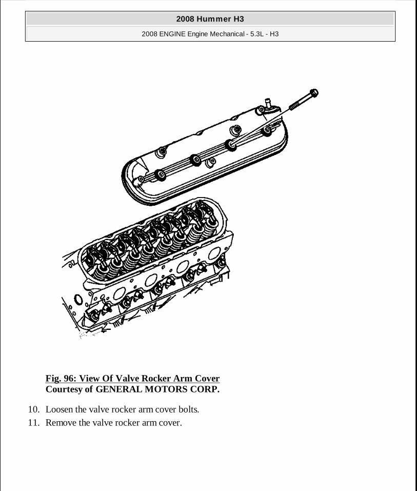
Fig. 96: View Of Valve Rocker Arm Cover Courtesy of GENERAL MOTORS CORP.
10. Loosen the valve rocker arm cover bolts. 11. Remove the valve rocker arm cover.
2008 Hummer H3
2008 ENGINE Engine Mechanical - 5.3L - H3
MY
Sunday, March 29, 2009 10:47:43 PM Page 151 © 2005 Mitchell Repair Information Company, LLC.
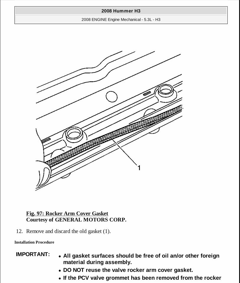
Fig. 97: Rocker Arm Cover Gasket Courtesy of GENERAL MOTORS CORP.
12. Remove and discard the old gasket (1).
Installation Procedure
IMPORTANT:� All gasket surfaces should be free of oil an/or oth er foreign
material during assembly. � DO NOT reuse the valve rocker arm cover gasket. � If the PCV valve grommet has been removed from the rocker
2008 Hummer H3
2008 ENGINE Engine Mechanical - 5.3L - H3
MY
Sunday, March 29, 2009 10:47:43 PM Page 152 © 2005 Mitchell Repair Information Company, LLC.
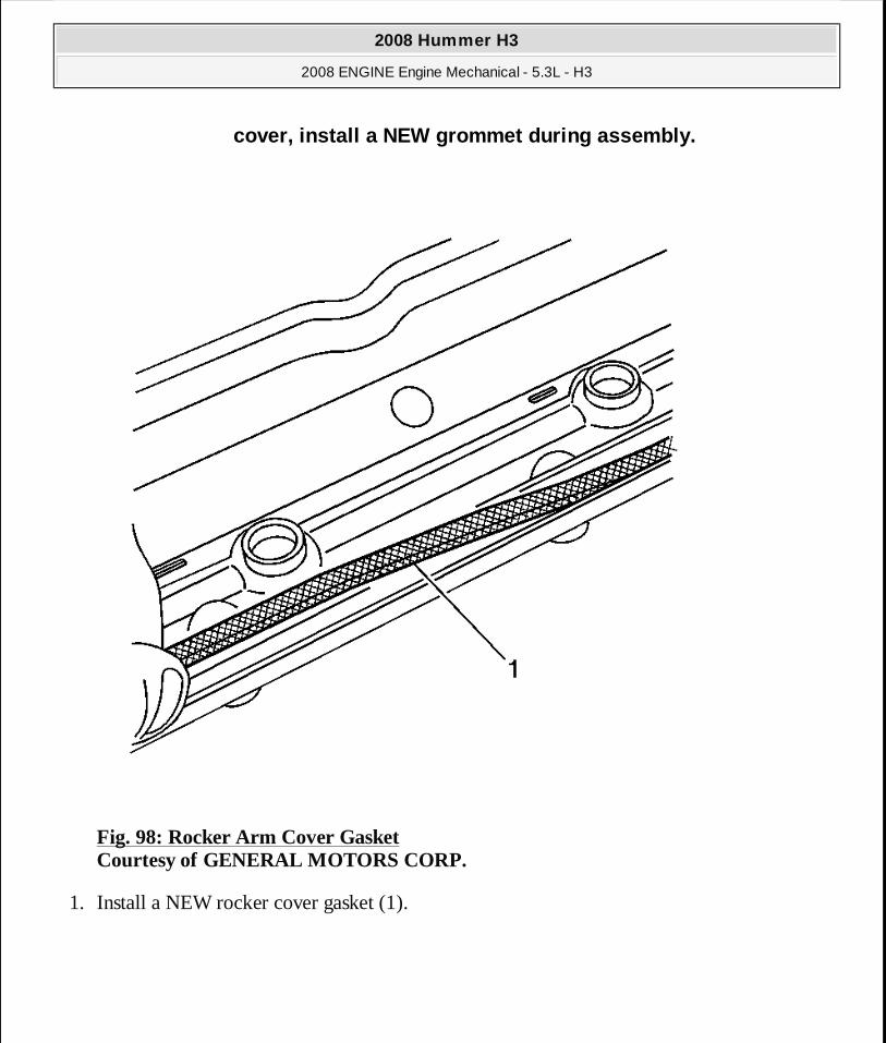
Fig. 98: Rocker Arm Cover Gasket Courtesy of GENERAL MOTORS CORP.
1. Install a NEW rocker cover gasket (1).
cover, install a NEW grommet during assembly.
2008 Hummer H3
2008 ENGINE Engine Mechanical - 5.3L - H3
MY
Sunday, March 29, 2009 10:47:43 PM Page 153 © 2005 Mitchell Repair Information Company, LLC.
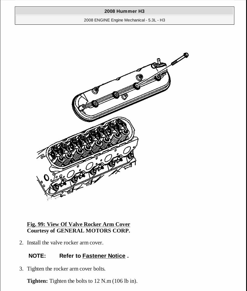
Fig. 99: View Of Valve Rocker Arm Cover Courtesy of GENERAL MOTORS CORP.
2. Install the valve rocker arm cover.
3. Tighten the rocker arm cover bolts.
Tighten: Tighten the bolts to 12 N.m (106 lb in).
NOTE: Refer to Fastener Notice .
2008 Hummer H3
2008 ENGINE Engine Mechanical - 5.3L - H3
MY
Sunday, March 29, 2009 10:47:43 PM Page 154 © 2005 Mitchell Repair Information Company, LLC.
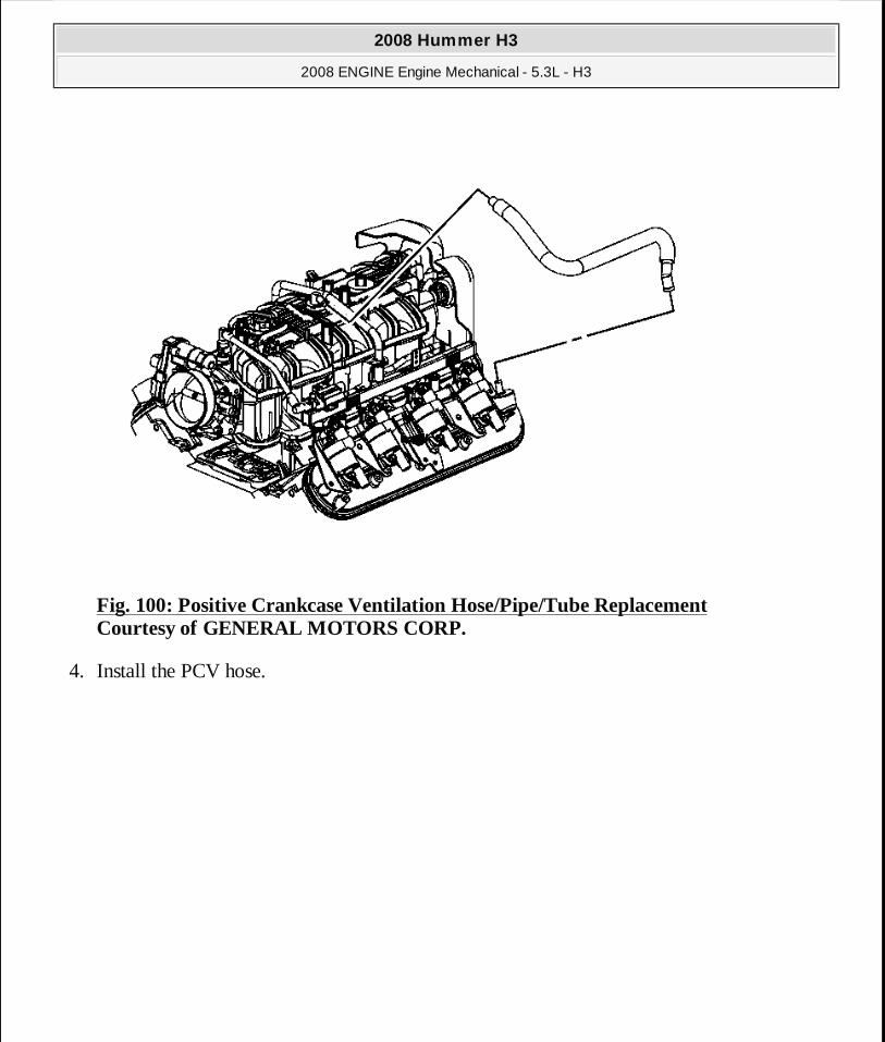
Fig. 100: Positive Crankcase Ventilation Hose/Pipe/Tube Replacement Courtesy of GENERAL MOTORS CORP.
4. Install the PCV hose.
2008 Hummer H3
2008 ENGINE Engine Mechanical - 5.3L - H3
MY
Sunday, March 29, 2009 10:47:43 PM Page 155 © 2005 Mitchell Repair Information Company, LLC.
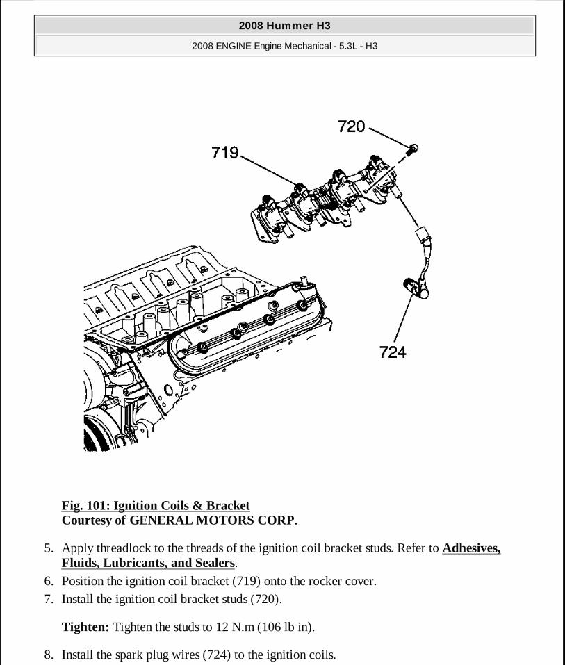
Fig. 101: Ignition Coils & Bracket Courtesy of GENERAL MOTORS CORP.
5. Apply threadlock to the threads of the ignition coil bracket studs. Refer to Adhesives, Fluids, Lubricants, and Sealers.
6. Position the ignition coil bracket (719) onto the rocker cover. 7. Install the ignition coil bracket studs (720).
Tighten: Tighten the studs to 12 N.m (106 lb in).
8. Install the spark plug wires (724) to the ignition coils.
2008 Hummer H3
2008 ENGINE Engine Mechanical - 5.3L - H3
MY
Sunday, March 29, 2009 10:47:43 PM Page 156 © 2005 Mitchell Repair Information Company, LLC.

Fig. 102: Valve Rocker Arm Cover Replacement - Left Side Courtesy of GENERAL MOTORS CORP.
9. Position the engine harness, as necessary. 10. Install the engine harness clip (4) to the ignition coil bracket stud. 11. Connect the engine harness electrical connector (1) to the ignition coil wire harness. 12. Install the CPA retainer (2).
13. Install the intake manifold cover. Refer to Upper Intake Manifold Sight Shield Replacement.
VALVE ROCKER ARM COVER REPLACEMENT - RIGHT SIDE
Removal Procedure
2008 Hummer H3
2008 ENGINE Engine Mechanical - 5.3L - H3
MY
Sunday, March 29, 2009 10:47:43 PM Page 157 © 2005 Mitchell Repair Information Company, LLC.

Fig. 103: Locating Electrical Components At Top Of Engine Courtesy of GENERAL MOTORS CORP.
1. Remove the upper intake manifold sight shield. Refer to Upper Intake Manifold Sight Shield Replacement.
2. Remove the connector position assurance (CPA) lock. 3. Disconnect the main electrical connector (1) to the ignition coil wire harness. 4. Remove the harness clips. 5. Reposition the engine harness, if necessary.
2008 Hummer H3
2008 ENGINE Engine Mechanical - 5.3L - H3
MY
Sunday, March 29, 2009 10:47:43 PM Page 158 © 2005 Mitchell Repair Information Company, LLC.
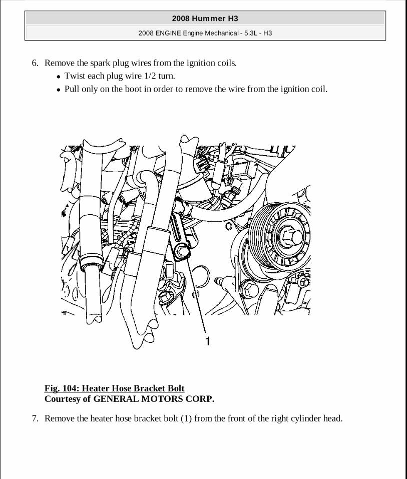
6. Remove the spark plug wires from the ignition coils. � Twist each plug wire 1/2 turn. � Pull only on the boot in order to remove the wire from the ignition coil.
Fig. 104: Heater Hose Bracket Bolt Courtesy of GENERAL MOTORS CORP.
7. Remove the heater hose bracket bolt (1) from the front of the right cylinder head.
2008 Hummer H3
2008 ENGINE Engine Mechanical - 5.3L - H3
MY
Sunday, March 29, 2009 10:47:43 PM Page 159 © 2005 Mitchell Repair Information Company, LLC.
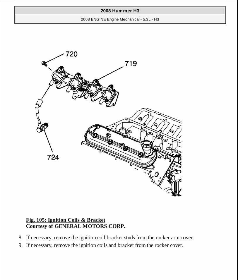
Fig. 105: Ignition Coils & Bracket Courtesy of GENERAL MOTORS CORP.
8. If necessary, remove the ignition coil bracket studs from the rocker arm cover. 9. If necessary, remove the ignition coils and bracket from the rocker cover.
2008 Hummer H3
2008 ENGINE Engine Mechanical - 5.3L - H3
MY
Sunday, March 29, 2009 10:47:43 PM Page 160 © 2005 Mitchell Repair Information Company, LLC.

Fig. 106: Vent Hose Courtesy of GENERAL MOTORS CORP.
10. Remove the vent hose (2) from the valve rocker arm cover (1).
2008 Hummer H3
2008 ENGINE Engine Mechanical - 5.3L - H3
MY
Sunday, March 29, 2009 10:47:43 PM Page 161 © 2005 Mitchell Repair Information Company, LLC.
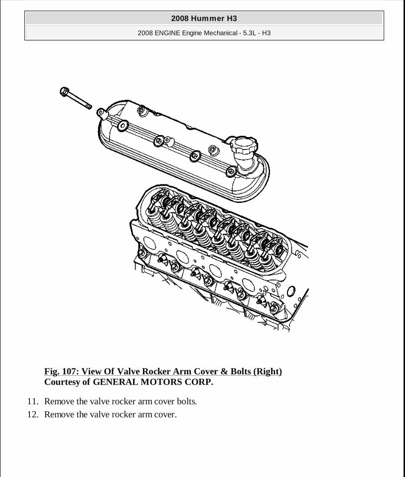
Fig. 107: View Of Valve Rocker Arm Cover & Bolts (Right) Courtesy of GENERAL MOTORS CORP.
11. Remove the valve rocker arm cover bolts. 12. Remove the valve rocker arm cover.
2008 Hummer H3
2008 ENGINE Engine Mechanical - 5.3L - H3
MY
Sunday, March 29, 2009 10:47:43 PM Page 162 © 2005 Mitchell Repair Information Company, LLC.
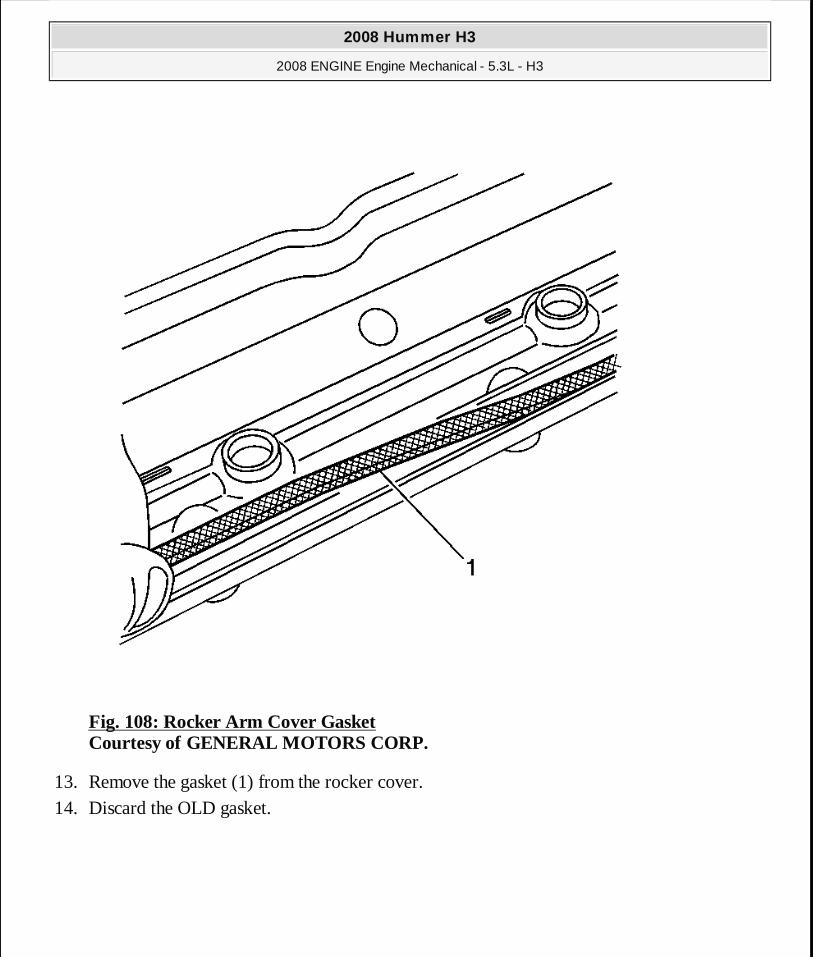
Fig. 108: Rocker Arm Cover Gasket Courtesy of GENERAL MOTORS CORP.
13. Remove the gasket (1) from the rocker cover. 14. Discard the OLD gasket.
2008 Hummer H3
2008 ENGINE Engine Mechanical - 5.3L - H3
MY
Sunday, March 29, 2009 10:47:43 PM Page 163 © 2005 Mitchell Repair Information Company, LLC.
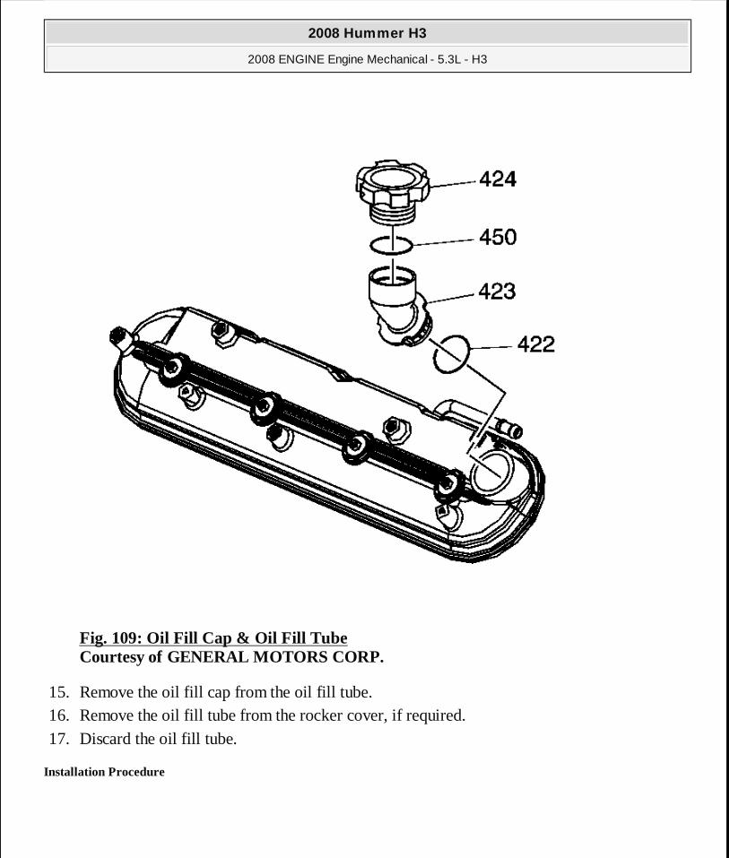
Fig. 109: Oil Fill Cap & Oil Fill Tube Courtesy of GENERAL MOTORS CORP.
15. Remove the oil fill cap from the oil fill tube. 16. Remove the oil fill tube from the rocker cover, if required. 17. Discard the oil fill tube.
Installation Procedure
2008 Hummer H3
2008 ENGINE Engine Mechanical - 5.3L - H3
MY
Sunday, March 29, 2009 10:47:43 PM Page 164 © 2005 Mitchell Repair Information Company, LLC.
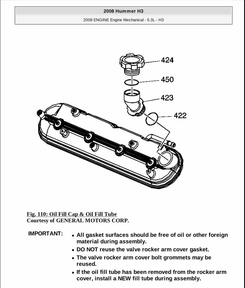
Fig. 110: Oil Fill Cap & Oil Fill Tube Courtesy of GENERAL MOTORS CORP.
IMPORTANT:� All gasket surfaces should be free of oil or other foreign
material during assembly. � DO NOT reuse the valve rocker arm cover gasket. � The valve rocker arm cover bolt grommets may be
reused. � If the oil fill tube has been removed from the rock er arm
cover, install a NEW fill tube during assembly.
2008 Hummer H3
2008 ENGINE Engine Mechanical - 5.3L - H3
MY
Sunday, March 29, 2009 10:47:43 PM Page 165 © 2005 Mitchell Repair Information Company, LLC.
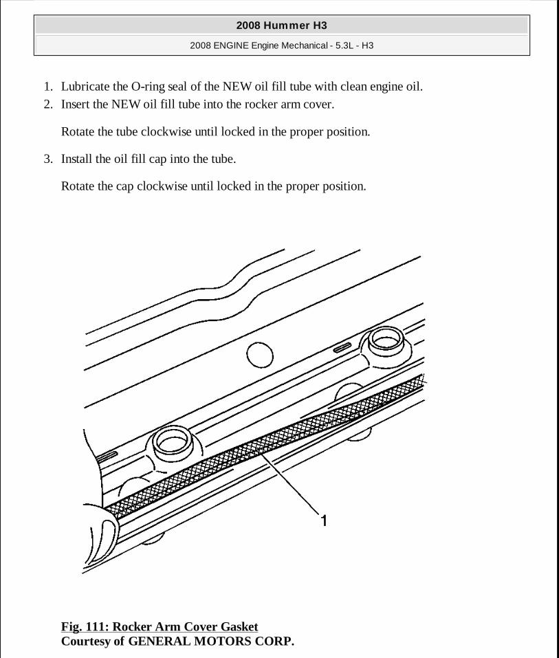
1. Lubricate the O-ring seal of the NEW oil fill tube with clean engine oil. 2. Insert the NEW oil fill tube into the rocker arm cover.
Rotate the tube clockwise until locked in the proper position.
3. Install the oil fill cap into the tube.
Rotate the cap clockwise until locked in the proper position.
Fig. 111: Rocker Arm Cover Gasket Courtesy of GENERAL MOTORS CORP.
2008 Hummer H3
2008 ENGINE Engine Mechanical - 5.3L - H3
MY
Sunday, March 29, 2009 10:47:43 PM Page 166 © 2005 Mitchell Repair Information Company, LLC.
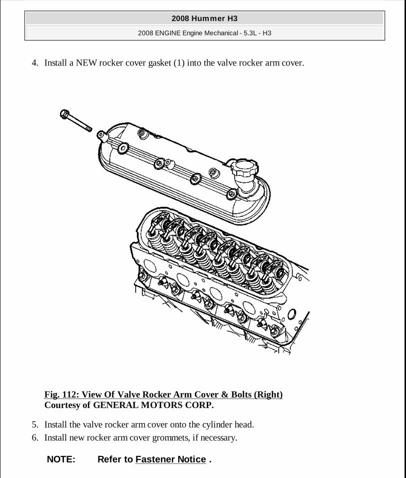
4. Install a NEW rocker cover gasket (1) into the valve rocker arm cover.
Fig. 112: View Of Valve Rocker Arm Cover & Bolts (Right) Courtesy of GENERAL MOTORS CORP.
5. Install the valve rocker arm cover onto the cylinder head. 6. Install new rocker arm cover grommets, if necessary.
NOTE: Refer to Fastener Notice .
2008 Hummer H3
2008 ENGINE Engine Mechanical - 5.3L - H3
MY
Sunday, March 29, 2009 10:47:43 PM Page 167 © 2005 Mitchell Repair Information Company, LLC.

7. Install the rocker arm cover bolts and grommets.
Tighten: Tighten the bolts to 12 N.m (106 lb in).
Fig. 113: Vent Hose Courtesy of GENERAL MOTORS CORP.
8. Install the vent hose (2) to the valve rocker arm cover (1).
2008 Hummer H3
2008 ENGINE Engine Mechanical - 5.3L - H3
MY
Sunday, March 29, 2009 10:47:43 PM Page 168 © 2005 Mitchell Repair Information Company, LLC.

Fig. 114: Ignition Coils & Bracket Courtesy of GENERAL MOTORS CORP.
9. Apply threadlock to the threads of the bracket bolts. Refer to Adhesives, Fluids, Lubricants, and Sealers for the correct part number.
10. If necessary, install the ignition coils and bracket to the rocker arm cover. 11. If necessary, install the ignition coil bracket studs to the rocker cover.
Tighten: Tighten the studs to 12 N.m (106 lb in).
2008 Hummer H3
2008 ENGINE Engine Mechanical - 5.3L - H3
MY
Sunday, March 29, 2009 10:47:43 PM Page 169 © 2005 Mitchell Repair Information Company, LLC.

Fig. 115: Heater Hose Bracket Bolt Courtesy of GENERAL MOTORS CORP.
12. Install the heater hose bracket bolt (1) to the front of the right cylinder head.
2008 Hummer H3
2008 ENGINE Engine Mechanical - 5.3L - H3
MY
Sunday, March 29, 2009 10:47:43 PM Page 170 © 2005 Mitchell Repair Information Company, LLC.

Fig. 116: Locating Electrical Components At Top Of Engine Courtesy of GENERAL MOTORS CORP.
13. Install the spark plug wires to the ignition coils. 14. Position the engine harness, if necessary. 15. Install the harness clips. 16. Connect the main electrical connector (1) feeding the ignition coils. 17. Install the CPA lock.
2008 Hummer H3
2008 ENGINE Engine Mechanical - 5.3L - H3
MY
Sunday, March 29, 2009 10:47:43 PM Page 171 © 2005 Mitchell Repair Information Company, LLC.
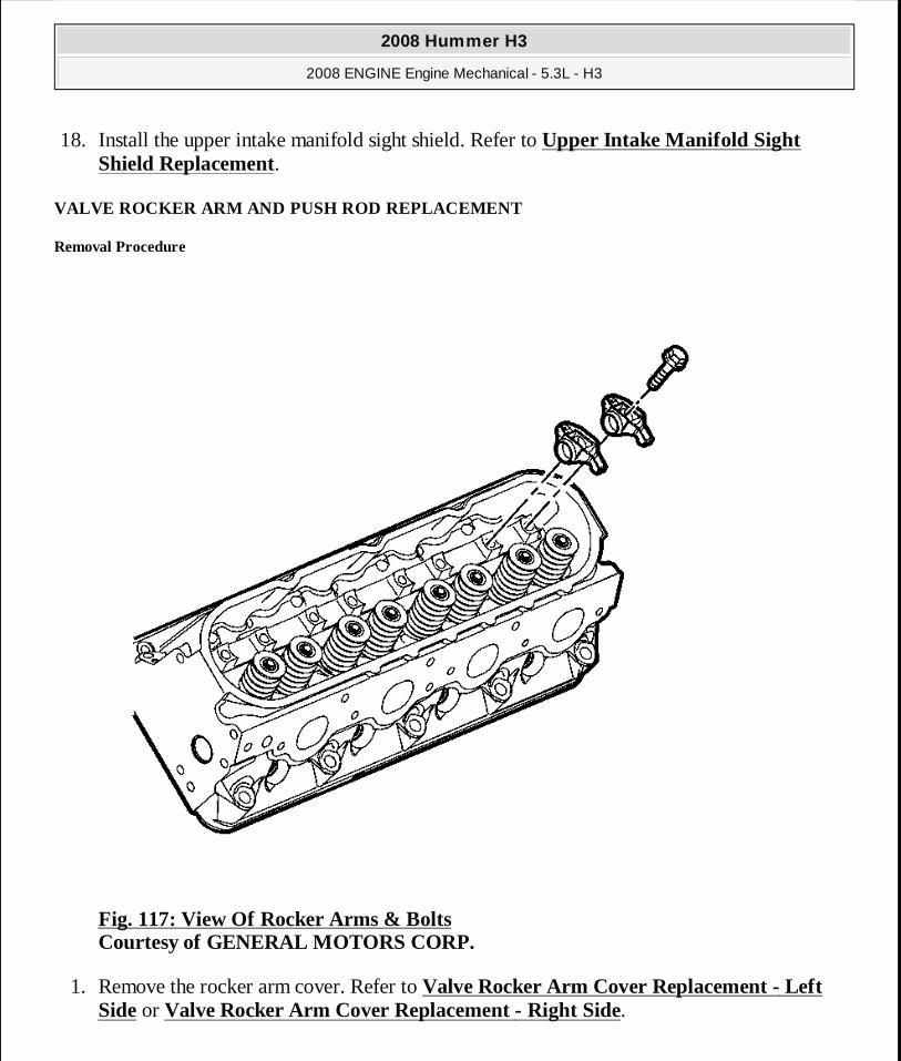
18. Install the upper intake manifold sight shield. Refer to Upper Intake Manifold Sight Shield Replacement.
VALVE ROCKER ARM AND PUSH ROD REPLACEMENT
Removal Procedure
Fig. 117: View Of Rocker Arms & Bolts Courtesy of GENERAL MOTORS CORP.
1. Remove the rocker arm cover. Refer to Valve Rocker Arm Cover Replacement - Left Side or Valve Rocker Arm Cover Replacement - Right Side.
2008 Hummer H3
2008 ENGINE Engine Mechanical - 5.3L - H3
MY
Sunday, March 29, 2009 10:47:43 PM Page 172 © 2005 Mitchell Repair Information Company, LLC.
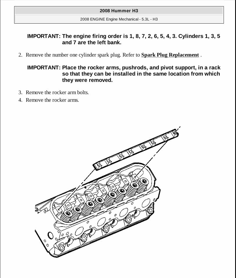
2. Remove the number one cylinder spark plug. Refer to Spark Plug Replacement .
3. Remove the rocker arm bolts. 4. Remove the rocker arms.
IMPORTANT: The engine firing order is 1, 8, 7, 2, 6, 5, 4, 3. Cylinders 1, 3, 5 and 7 are the left bank.
IMPORTANT: Place the rocker arms, pushrods, and pivo t support, in a rack so that they can be installed in the same location from which they were removed.
2008 Hummer H3
2008 ENGINE Engine Mechanical - 5.3L - H3
MY
Sunday, March 29, 2009 10:47:43 PM Page 173 © 2005 Mitchell Repair Information Company, LLC.
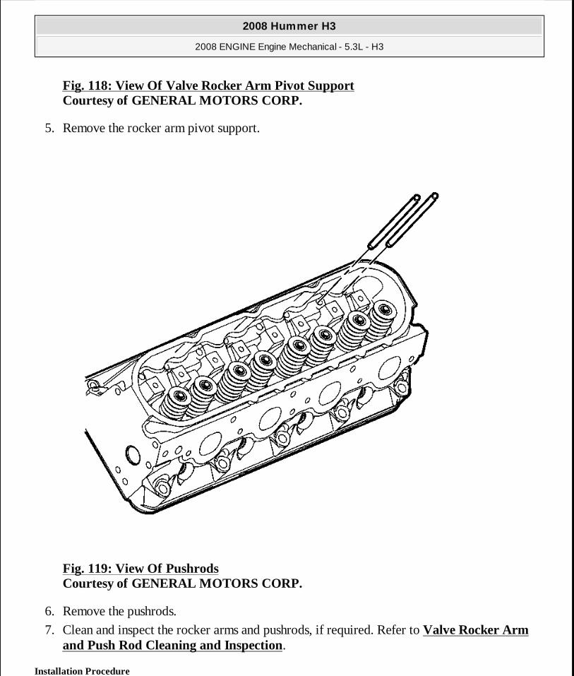
Fig. 118: View Of Valve Rocker Arm Pivot Support Courtesy of GENERAL MOTORS CORP.
5. Remove the rocker arm pivot support.
Fig. 119: View Of Pushrods Courtesy of GENERAL MOTORS CORP.
6. Remove the pushrods.
7. Clean and inspect the rocker arms and pushrods, if required. Refer to Valve Rocker Arm and Push Rod Cleaning and Inspection.
Installation Procedure
2008 Hummer H3
2008 ENGINE Engine Mechanical - 5.3L - H3
MY
Sunday, March 29, 2009 10:47:43 PM Page 174 © 2005 Mitchell Repair Information Company, LLC.
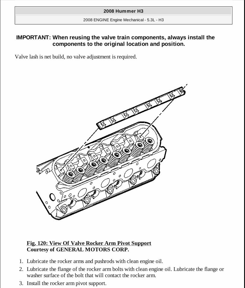
Valve lash is net build, no valve adjustment is required.
Fig. 120: View Of Valve Rocker Arm Pivot Support Courtesy of GENERAL MOTORS CORP.
1. Lubricate the rocker arms and pushrods with clean engine oil. 2. Lubricate the flange of the rocker arm bolts with clean engine oil. Lubricate the flange or
washer surface of the bolt that will contact the rocker arm. 3. Install the rocker arm pivot support.
IMPORTANT: When reusing the valve train components, always install the components to the original location and position.
2008 Hummer H3
2008 ENGINE Engine Mechanical - 5.3L - H3
MY
Sunday, March 29, 2009 10:47:43 PM Page 175 © 2005 Mitchell Repair Information Company, LLC.
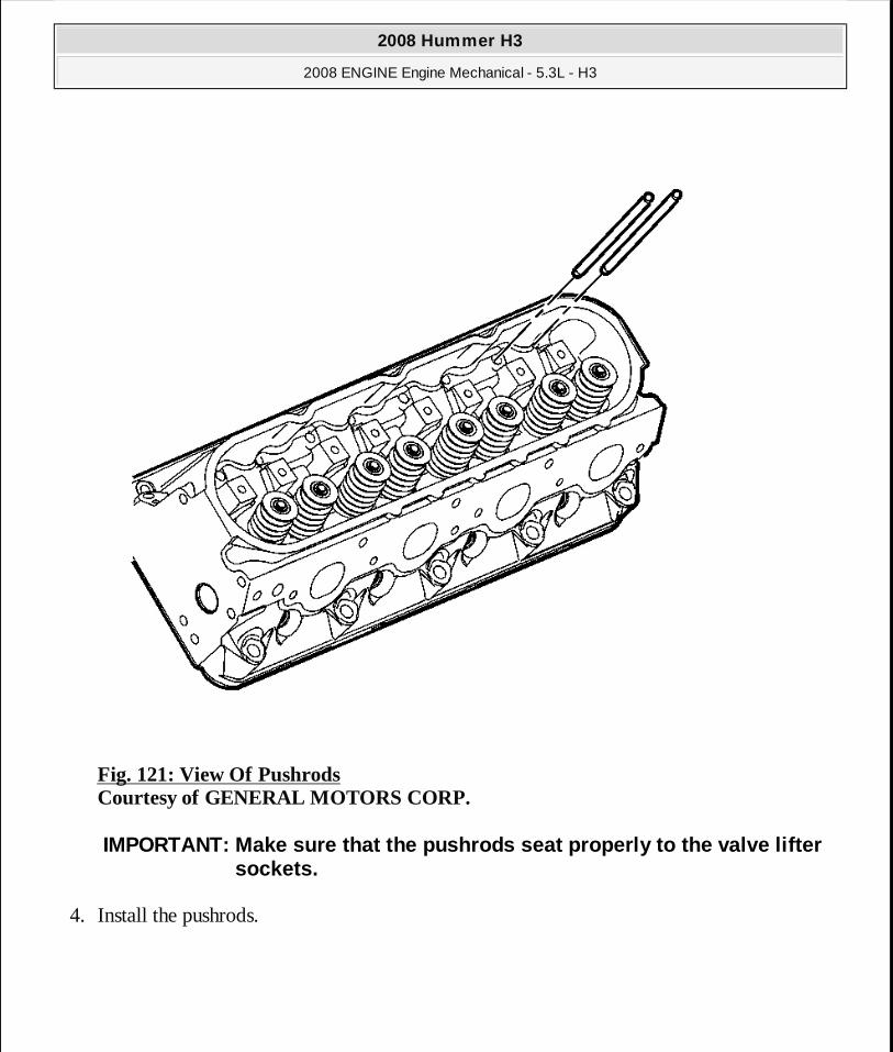
Fig. 121: View Of Pushrods Courtesy of GENERAL MOTORS CORP.
4. Install the pushrods.
IMPORTANT: Make sure that the pushrods seat properly to the valve lifter sockets.
2008 Hummer H3
2008 ENGINE Engine Mechanical - 5.3L - H3
MY
Sunday, March 29, 2009 10:47:43 PM Page 176 © 2005 Mitchell Repair Information Company, LLC.
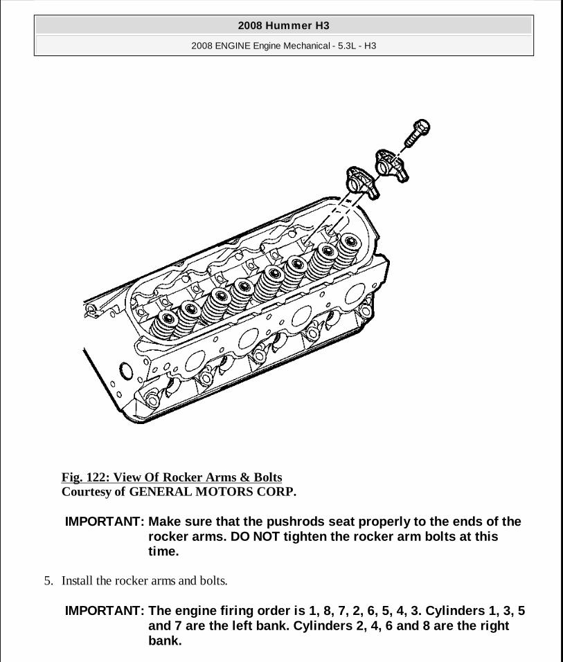
Fig. 122: View Of Rocker Arms & Bolts Courtesy of GENERAL MOTORS CORP.
5. Install the rocker arms and bolts.
IMPORTANT: Make sure that the pushrods seat properly to the ends of the rocker arms. DO NOT tighten the rocker arm bolts at this time.
IMPORTANT: The engine firing order is 1, 8, 7, 2, 6, 5, 4, 3. Cylinders 1, 3, 5 and 7 are the left bank. Cylinders 2, 4, 6 and 8 ar e the right bank.
2008 Hummer H3
2008 ENGINE Engine Mechanical - 5.3L - H3
MY
Sunday, March 29, 2009 10:47:44 PM Page 177 © 2005 Mitchell Repair Information Company, LLC.

6. Rotate the crankshaft until the number one piston is at top dead center (TDC) of the compression stroke. In this position, the number one cylinder rocker arms will be off lobe lift.
7. With the engine in the number one firing position, tighten the following rocker arm bolts:
Tighten: � Tighten cylinders 1,2,7 and 8 exhaust valve rocker arm bolts to 30 N.m (22 lb ft). � Tighten cylinders 1,3,4 and 5 intake valve rocker arm bolts to 30 N.m (22 lb ft).
8. Rotate the crankshaft 360 degrees. 9. Tighten the following rocker arm bolts:
Tighten: � Tighten cylinders 3, 4, 5 and 6 exhaust valve rocker arm bolts to 30 N.m (22 lb ft). � Tighten cylinders 2, 6, 7 and 8 intake valve rocker arm bolts to 30 N.m (22 lb ft).
10. Install the number one cylinder spark plug. Refer to Spark Plug Replacement . 11. Install the rocker arm cover. Refer to Valve Rocker Arm Cover Replacement - Left Side
or Valve Rocker Arm Cover Replacement - Right Side.
VALVE STEM OIL SEAL AND VALVE SPRING REPLACEMENT
Tools Required
� J 22794 Spark Plug Port Adapter. See Special Tools. � J 38606 Valve Spring Compressor. See Special Tools.
Removal Procedure
NOTE: Refer to Fastener Notice .
2008 Hummer H3
2008 ENGINE Engine Mechanical - 5.3L - H3
MY
Sunday, March 29, 2009 10:47:44 PM Page 178 © 2005 Mitchell Repair Information Company, LLC.
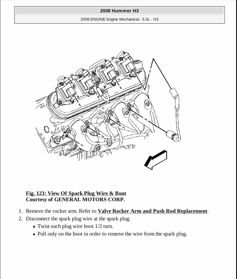
Fig. 123: View Of Spark Plug Wire & Boot Courtesy of GENERAL MOTORS CORP.
1. Remove the rocker arm. Refer to Valve Rocker Arm and Push Rod Replacement. 2. Disconnect the spark plug wire at the spark plug.
� Twist each plug wire boot 1/2 turn. � Pull only on the boot in order to remove the wire from the spark plug.
2008 Hummer H3
2008 ENGINE Engine Mechanical - 5.3L - H3
MY
Sunday, March 29, 2009 10:47:44 PM Page 179 © 2005 Mitchell Repair Information Company, LLC.

Fig. 124: View Of Spark Plug And Sparkplug Seat Courtesy of GENERAL MOTORS CORP.
3. Loosen the spark plug 1 or 2 turns. 4. Brush or air blast away any dirt or debris from around the spark plug. 5. Remove the spark plug.
IMPORTANT: Remove the spark plugs from the cylinder head with the engine at room temperature.
2008 Hummer H3
2008 ENGINE Engine Mechanical - 5.3L - H3
MY
Sunday, March 29, 2009 10:47:44 PM Page 180 © 2005 Mitchell Repair Information Company, LLC.
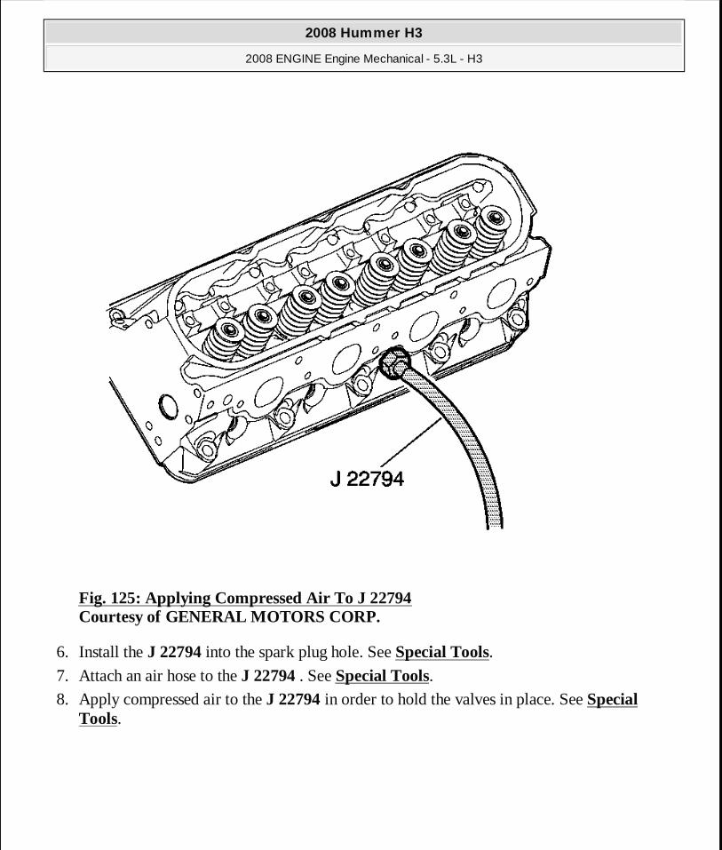
Fig. 125: Applying Compressed Air To J 22794 Courtesy of GENERAL MOTORS CORP.
6. Install the J 22794 into the spark plug hole. See Special Tools. 7. Attach an air hose to the J 22794 . See Special Tools. 8. Apply compressed air to the J 22794 in order to hold the valves in place. See Special
Tools.
2008 Hummer H3
2008 ENGINE Engine Mechanical - 5.3L - H3
MY
Sunday, March 29, 2009 10:47:44 PM Page 181 © 2005 Mitchell Repair Information Company, LLC.
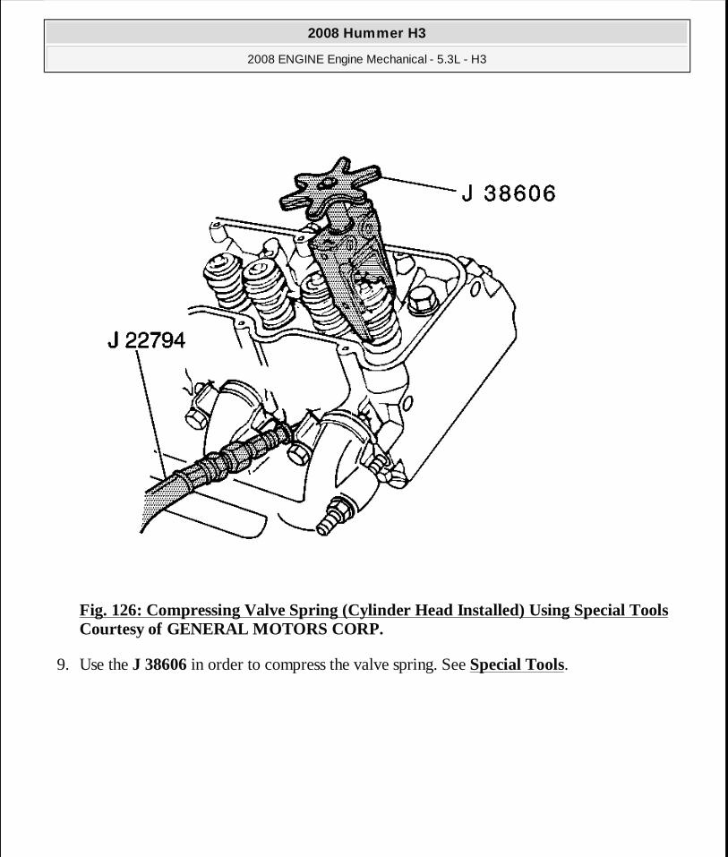
Fig. 126: Compressing Valve Spring (Cylinder Head Installed) Using Special Tools Courtesy of GENERAL MOTORS CORP.
9. Use the J 38606 in order to compress the valve spring. See Special Tools.
2008 Hummer H3
2008 ENGINE Engine Mechanical - 5.3L - H3
MY
Sunday, March 29, 2009 10:47:44 PM Page 182 © 2005 Mitchell Repair Information Company, LLC.
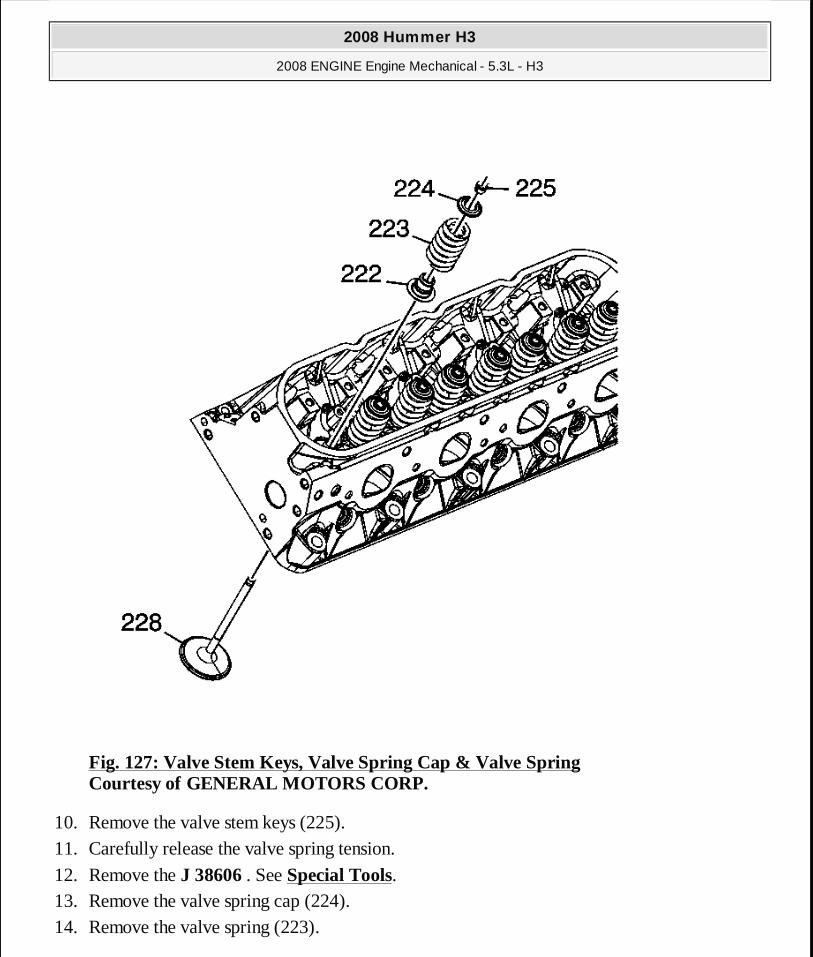
Fig. 127: Valve Stem Keys, Valve Spring Cap & Valve Spring Courtesy of GENERAL MOTORS CORP.
10. Remove the valve stem keys (225). 11. Carefully release the valve spring tension.
12. Remove the J 38606 . See Special Tools. 13. Remove the valve spring cap (224). 14. Remove the valve spring (223).
2008 Hummer H3
2008 ENGINE Engine Mechanical - 5.3L - H3
MY
Sunday, March 29, 2009 10:47:44 PM Page 183 © 2005 Mitchell Repair Information Company, LLC.
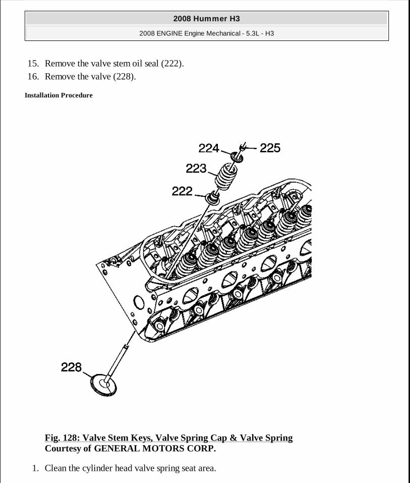
15. Remove the valve stem oil seal (222). 16. Remove the valve (228).
Installation Procedure
Fig. 128: Valve Stem Keys, Valve Spring Cap & Valve Spring Courtesy of GENERAL MOTORS CORP.
1. Clean the cylinder head valve spring seat area.
2008 Hummer H3
2008 ENGINE Engine Mechanical - 5.3L - H3
MY
Sunday, March 29, 2009 10:47:44 PM Page 184 © 2005 Mitchell Repair Information Company, LLC.
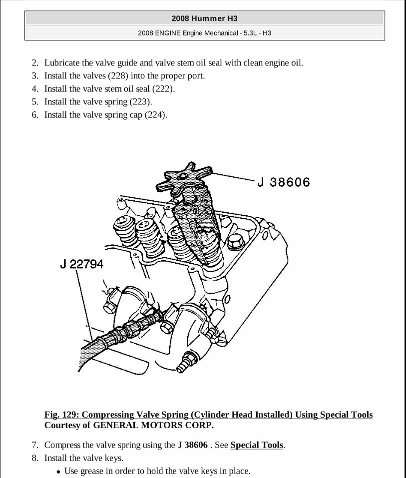
2. Lubricate the valve guide and valve stem oil seal with clean engine oil. 3. Install the valves (228) into the proper port. 4. Install the valve stem oil seal (222). 5. Install the valve spring (223). 6. Install the valve spring cap (224).
Fig. 129: Compressing Valve Spring (Cylinder Head Installed) Using Special Tools Courtesy of GENERAL MOTORS CORP.
7. Compress the valve spring using the J 38606 . See Special Tools. 8. Install the valve keys.
� Use grease in order to hold the valve keys in place.
2008 Hummer H3
2008 ENGINE Engine Mechanical - 5.3L - H3
MY
Sunday, March 29, 2009 10:47:44 PM Page 185 © 2005 Mitchell Repair Information Company, LLC.
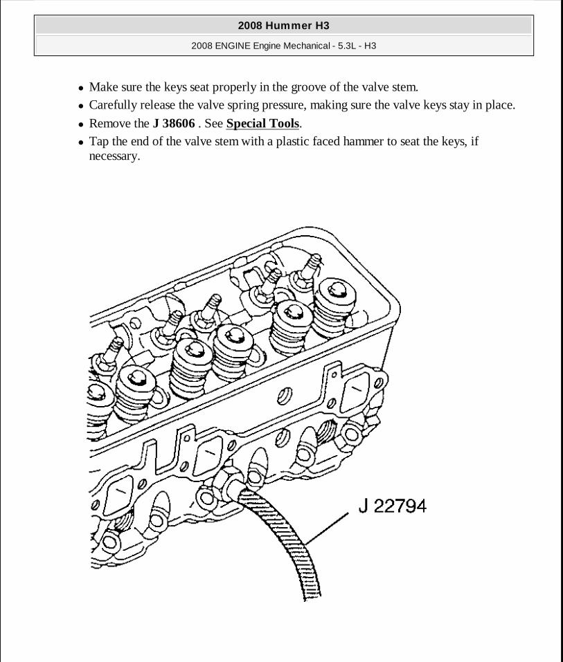
� Make sure the keys seat properly in the groove of the valve stem. � Carefully release the valve spring pressure, making sure the valve keys stay in place.
� Remove the J 38606 . See Special Tools. � Tap the end of the valve stem with a plastic faced hammer to seat the keys, if
necessary.
2008 Hummer H3
2008 ENGINE Engine Mechanical - 5.3L - H3
MY
Sunday, March 29, 2009 10:47:44 PM Page 186 © 2005 Mitchell Repair Information Company, LLC.

Fig. 130: View Of J 22794 Courtesy of GENERAL MOTORS CORP.
9. Remove the J 22794 from the spark plug port. See Special Tools.
Fig. 131: View Of Spark Plug And Sparkplug Seat Courtesy of GENERAL MOTORS CORP.
10. Hand start the spark plug.
Tighten: Tighten the spark plug to 15 N.m (11 lb ft).
11. Install the spark plug wires at the ignition coil. 12. Install the spark plug wire to the spark plug. 13. Inspect the wires for proper installation:
� Push sideways on each boot in order to check for proper installation. � Reinstall any loose boot.
14. Install the rocker arm. Refer to Valve Rocker Arm and Push Rod Replacement.
NOTE: Refer to Fastener Notice .
2008 Hummer H3
2008 ENGINE Engine Mechanical - 5.3L - H3
MY
Sunday, March 29, 2009 10:47:44 PM Page 187 © 2005 Mitchell Repair Information Company, LLC.

OIL LEVEL INDICATOR AND TUBE REPLACEMENT
Removal Procedure
Fig. 132: View Of Oil Level Indicator Tube Courtesy of GENERAL MOTORS CORP.
1. Remove the cylinder number 2 spark plug and wire. Refer to Spark Plug Replacement .
2008 Hummer H3
2008 ENGINE Engine Mechanical - 5.3L - H3
MY
Sunday, March 29, 2009 10:47:44 PM Page 188 © 2005 Mitchell Repair Information Company, LLC.

2. Remove the oil level indicator from the tube. 3. Remove the oil level indicator tube bolt. 4. Remove the oil level indicator tube from the engine block.
5. Inspect the O-ring seal for cuts or damage. 6. Remove the O-ring seal from the tube, if required.
Installation Procedure
IMPORTANT: The O-ring seal may be reused if not cut or damaged.
2008 Hummer H3
2008 ENGINE Engine Mechanical - 5.3L - H3
MY
Sunday, March 29, 2009 10:47:44 PM Page 189 © 2005 Mitchell Repair Information Company, LLC.

Fig. 133: View Of Oil Level Indicator Tube Courtesy of GENERAL MOTORS CORP.
1. Lubricate the O-ring seal with clean engine oil. 2. Install the O-ring seal onto the oil level indicator tube. 3. Install the oil level indicator tube behind the exhaust manifold.
4. Raise and suitably support the vehicle. Refer to Lifting and Jacking the Vehicle .
2008 Hummer H3
2008 ENGINE Engine Mechanical - 5.3L - H3
MY
Sunday, March 29, 2009 10:47:44 PM Page 190 © 2005 Mitchell Repair Information Company, LLC.
5. Install the oil level indicator tube into the block. Install the tube with the collar flush to the block.
6. Lower the vehicle.
7. Install the oil level indicator tube bolt.
Tighten: Tighten the bolt to 25 N.m (18 lb ft).
8. Install the oil level indicator to the tube.
9. Install the cylinder number 2 spark plug and wire. Refer to Spark Plug Replacement .
CYLINDER HEAD REPLACEMENT - LEFT SIDE
Tools Required
� J 45059 Angle Meter
� J 42385-200 Common Thread Repair Kit. See Special Tools.
Removal Procedure
NOTE: Refer to Fastener Notice .
2008 Hummer H3
2008 ENGINE Engine Mechanical - 5.3L - H3
MY
Sunday, March 29, 2009 10:47:44 PM Page 191 © 2005 Mitchell Repair Information Company, LLC.
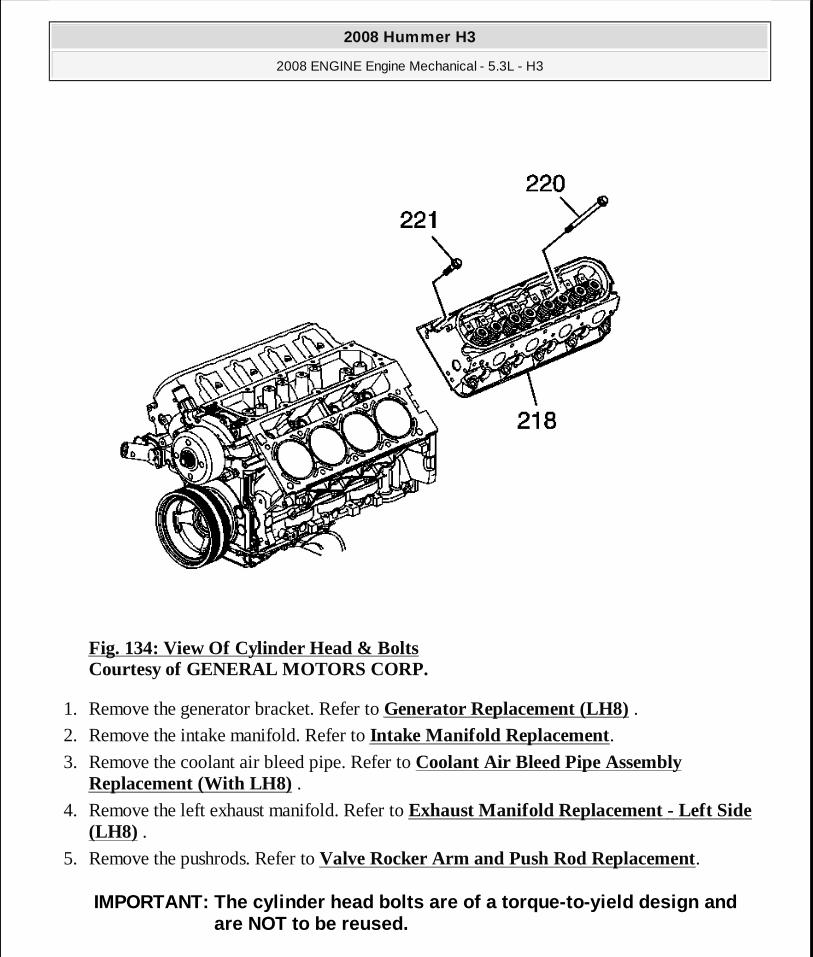
Fig. 134: View Of Cylinder Head & Bolts Courtesy of GENERAL MOTORS CORP.
1. Remove the generator bracket. Refer to Generator Replacement (LH8) . 2. Remove the intake manifold. Refer to Intake Manifold Replacement. 3. Remove the coolant air bleed pipe. Refer to Coolant Air Bleed Pipe Assembly
Replacement (With LH8) . 4. Remove the left exhaust manifold. Refer to Exhaust Manifold Replacement - Left Side
(LH8) . 5. Remove the pushrods. Refer to Valve Rocker Arm and Push Rod Replacement.
IMPORTANT: The cylinder head bolts are of a torque-t o-yield design and are NOT to be reused.
2008 Hummer H3
2008 ENGINE Engine Mechanical - 5.3L - H3
MY
Sunday, March 29, 2009 10:47:44 PM Page 192 © 2005 Mitchell Repair Information Company, LLC.
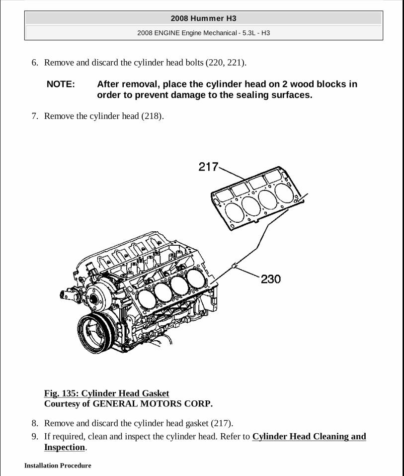
6. Remove and discard the cylinder head bolts (220, 221).
7. Remove the cylinder head (218).
Fig. 135: Cylinder Head Gasket Courtesy of GENERAL MOTORS CORP.
8. Remove and discard the cylinder head gasket (217).
9. If required, clean and inspect the cylinder head. Refer to Cylinder Head Cleaning and Inspection.
Installation Procedure
NOTE: After removal, place the cylinder head on 2 wo od blocks in order to prevent damage to the sealing surfaces.
2008 Hummer H3
2008 ENGINE Engine Mechanical - 5.3L - H3
MY
Sunday, March 29, 2009 10:47:44 PM Page 193 © 2005 Mitchell Repair Information Company, LLC.
CAUTION: Wear safety glasses in order to avoid eye d amage.
NOTE: Clean all dirt, debris, and coolant from the e ngine block cylinder head bolt holes. Failure to remove all foreign mate rial may result in damaged threads, improperly tightened fasteners or damage to components.
IMPORTANT:� Do not reuse the cylinder head bolts. Install NEW c ylinder
head bolts during assembly. � Do not use any type of sealant on the cylinder head gasket
(unless specified).
2008 Hummer H3
2008 ENGINE Engine Mechanical - 5.3L - H3
MY
Sunday, March 29, 2009 10:47:44 PM Page 194 © 2005 Mitchell Repair Information Company, LLC.

Fig. 136: Checking Cylinder Head Bolt Holes Courtesy of GENERAL MOTORS CORP.
1. Clean the engine block cylinder head bolt holes, if required. Thread repair tool J 42385-107, found in J 42385-200 may be used to clean the threads of old threadlocking material. See Special Tools.
2. Spray cleaner GM P/N 12346139, P/N 12377981 (Canadian P/N 10953463), or equivalent into the hole.
3. Clean the cylinder head bolt holes with compressed air. 4. Check the cylinder head locating pins for proper installation (a) 8.3 mm (0.327 in).
2008 Hummer H3
2008 ENGINE Engine Mechanical - 5.3L - H3
MY
Sunday, March 29, 2009 10:47:44 PM Page 195 © 2005 Mitchell Repair Information Company, LLC.

Fig. 137: Cylinder Head Gasket Courtesy of GENERAL MOTORS CORP.
5. Install the NEW cylinder head gasket (217) onto the locating pins.
IMPORTANT: When properly installed, with FRONT on th e left side, the tab on the cylinder head gasket should be located left of center.
2008 Hummer H3
2008 ENGINE Engine Mechanical - 5.3L - H3
MY
Sunday, March 29, 2009 10:47:44 PM Page 196 © 2005 Mitchell Repair Information Company, LLC.

Fig. 138: View Of Cylinder Head & Bolts Courtesy of GENERAL MOTORS CORP.
6. Install the cylinder head (218) onto the locating pins. 7. Install the NEW cylinder head bolts (220, 221).
2008 Hummer H3
2008 ENGINE Engine Mechanical - 5.3L - H3
MY
Sunday, March 29, 2009 10:47:44 PM Page 197 © 2005 Mitchell Repair Information Company, LLC.
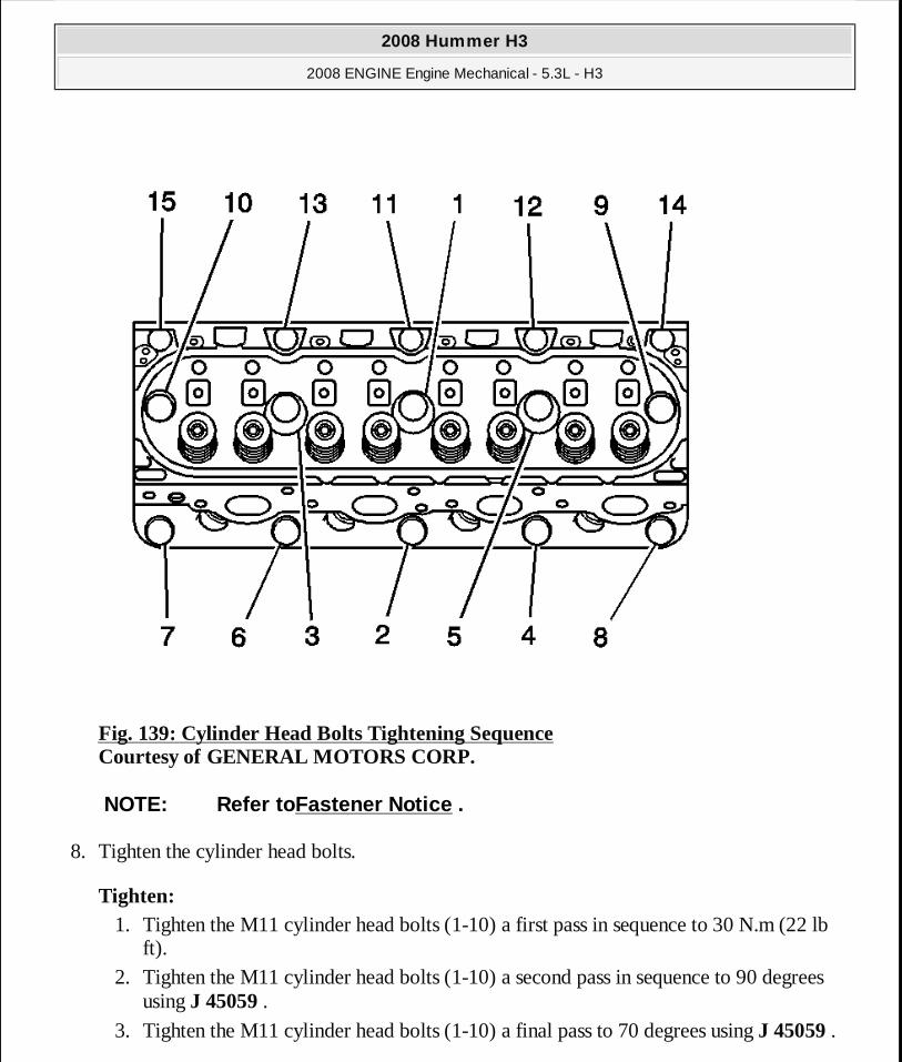
Fig. 139: Cylinder Head Bolts Tightening Sequence Courtesy of GENERAL MOTORS CORP.
8. Tighten the cylinder head bolts.
Tighten: 1. Tighten the M11 cylinder head bolts (1-10) a first pass in sequence to 30 N.m (22 lb
ft). 2. Tighten the M11 cylinder head bolts (1-10) a second pass in sequence to 90 degrees
using J 45059 .
3. Tighten the M11 cylinder head bolts (1-10) a final pass to 70 degrees using J 45059 .
NOTE: Refer toFastener Notice .
2008 Hummer H3
2008 ENGINE Engine Mechanical - 5.3L - H3
MY
Sunday, March 29, 2009 10:47:44 PM Page 198 © 2005 Mitchell Repair Information Company, LLC.
4. Tighten the M8 cylinder head bolts (11-15) to 30 N.m (22 lb ft). Begin with the center bolt (11) and alternating side-to-side, work outward tightening all of the bolts.
9. Install the pushrods. Refer to Valve Rocker Arm and Push Rod Replacement. 10. Install the left exhaust manifold. Refer to Exhaust Manifold Replacement - Left Side
(LH8) . 11. Install the coolant air bleed pipe. Refer to Coolant Air Bleed Pipe Assembly
Replacement (With LH8) . 12. Install the intake manifold. Refer to Intake Manifold Replacement. 13. Install the generator bracket. Refer to Generator Replacement (LH8) .
CYLINDER HEAD REPLACEMENT - RIGHT SIDE
Tools Required
� J 45059 Angle Meter
� J 42385-200 Common Thread Repair Kit. See Special Tools.
Removal Procedure
2008 Hummer H3
2008 ENGINE Engine Mechanical - 5.3L - H3
MY
Sunday, March 29, 2009 10:47:44 PM Page 199 © 2005 Mitchell Repair Information Company, LLC.
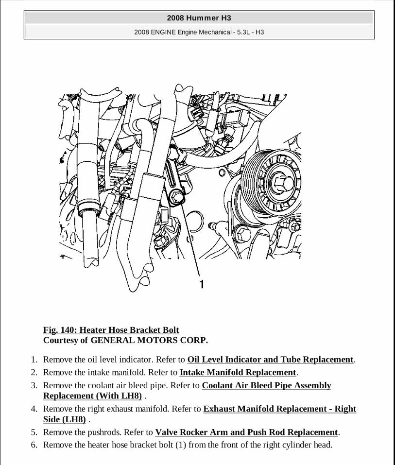
Fig. 140: Heater Hose Bracket Bolt Courtesy of GENERAL MOTORS CORP.
1. Remove the oil level indicator. Refer to Oil Level Indicator and Tube Replacement. 2. Remove the intake manifold. Refer to Intake Manifold Replacement. 3. Remove the coolant air bleed pipe. Refer to Coolant Air Bleed Pipe Assembly
Replacement (With LH8) . 4. Remove the right exhaust manifold. Refer to Exhaust Manifold Replacement - Right
Side (LH8) . 5. Remove the pushrods. Refer to Valve Rocker Arm and Push Rod Replacement. 6. Remove the heater hose bracket bolt (1) from the front of the right cylinder head.
2008 Hummer H3
2008 ENGINE Engine Mechanical - 5.3L - H3
MY
Sunday, March 29, 2009 10:47:44 PM Page 200 © 2005 Mitchell Repair Information Company, LLC.
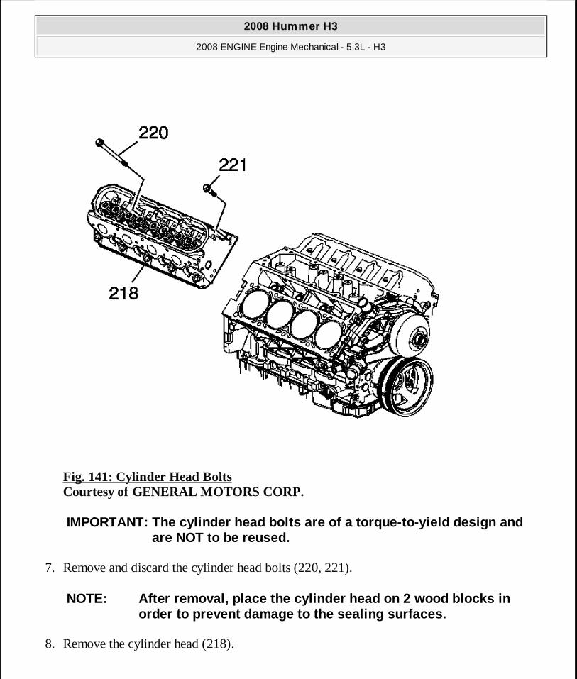
Fig. 141: Cylinder Head Bolts Courtesy of GENERAL MOTORS CORP.
7. Remove and discard the cylinder head bolts (220, 221).
8. Remove the cylinder head (218).
IMPORTANT: The cylinder head bolts are of a torque-t o-yield design and are NOT to be reused.
NOTE: After removal, place the cylinder head on 2 wo od blocks in order to prevent damage to the sealing surfaces.
2008 Hummer H3
2008 ENGINE Engine Mechanical - 5.3L - H3
MY
Sunday, March 29, 2009 10:47:44 PM Page 201 © 2005 Mitchell Repair Information Company, LLC.
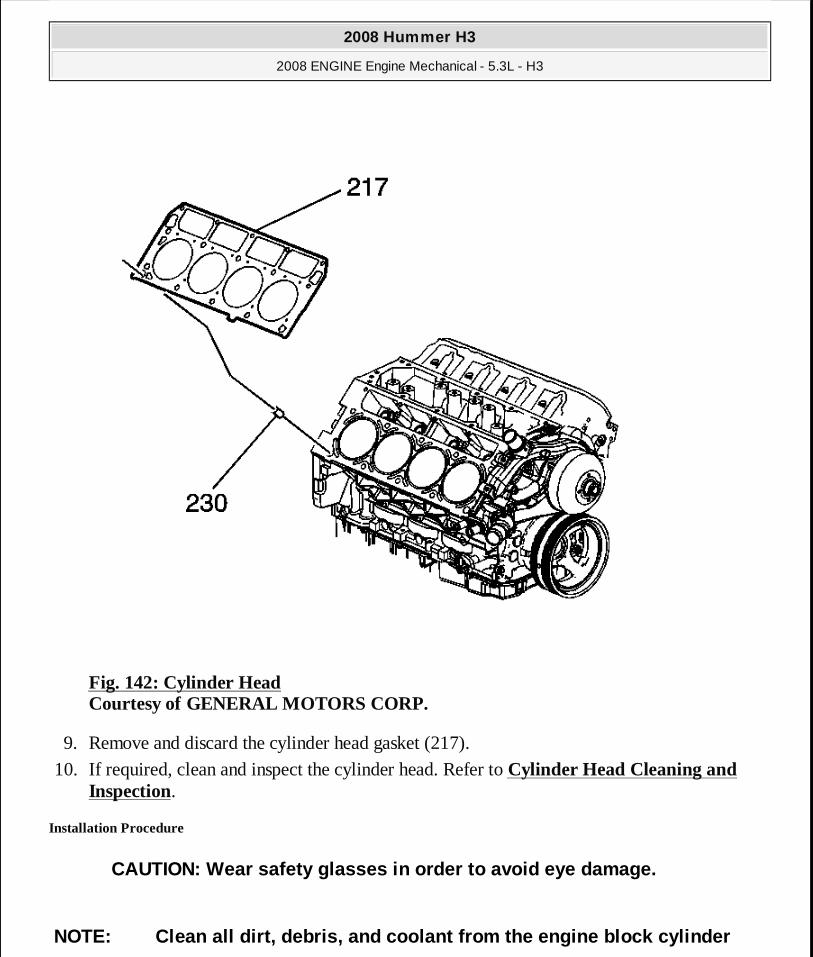
Fig. 142: Cylinder Head Courtesy of GENERAL MOTORS CORP.
9. Remove and discard the cylinder head gasket (217).
10. If required, clean and inspect the cylinder head. Refer to Cylinder Head Cleaning and Inspection.
Installation Procedure
CAUTION: Wear safety glasses in order to avoid eye d amage.
NOTE: Clean all dirt, debris, and coolant from the e ngine block cylinder
2008 Hummer H3
2008 ENGINE Engine Mechanical - 5.3L - H3
MY
Sunday, March 29, 2009 10:47:45 PM Page 202 © 2005 Mitchell Repair Information Company, LLC.
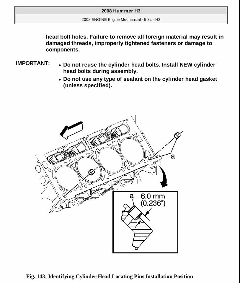
Fig. 143: Identifying Cylinder Head Locating Pins Installation Position
head bolt holes. Failure to remove all foreign mate rial may result in damaged threads, improperly tightened fasteners or damage to components.
IMPORTANT:� Do not reuse the cylinder head bolts. Install NEW c ylinder
head bolts during assembly. � Do not use any type of sealant on the cylinder head gasket
(unless specified).
2008 Hummer H3
2008 ENGINE Engine Mechanical - 5.3L - H3
MY
Sunday, March 29, 2009 10:47:45 PM Page 203 © 2005 Mitchell Repair Information Company, LLC.

Courtesy of GENERAL MOTORS CORP.
1. Clean the engine block cylinder head bolt holes, if required. Thread repair tool J 42385-107, found in J 42385-200 may be used to clean the threads of old threadlocking material. See Special Tools.
2. Spray cleaner GM P/N 12346139, P/N 12377981 (Canadian P/N 10953463), or equivalent into the hole.
3. Clean the cylinder head bolt holes with compressed air. 4. Check the cylinder head locating pins for proper installation (a) 8.3 mm (0.327 in).
Fig. 144: Cylinder Head Courtesy of GENERAL MOTORS CORP.
2008 Hummer H3
2008 ENGINE Engine Mechanical - 5.3L - H3
MY
Sunday, March 29, 2009 10:47:45 PM Page 204 © 2005 Mitchell Repair Information Company, LLC.
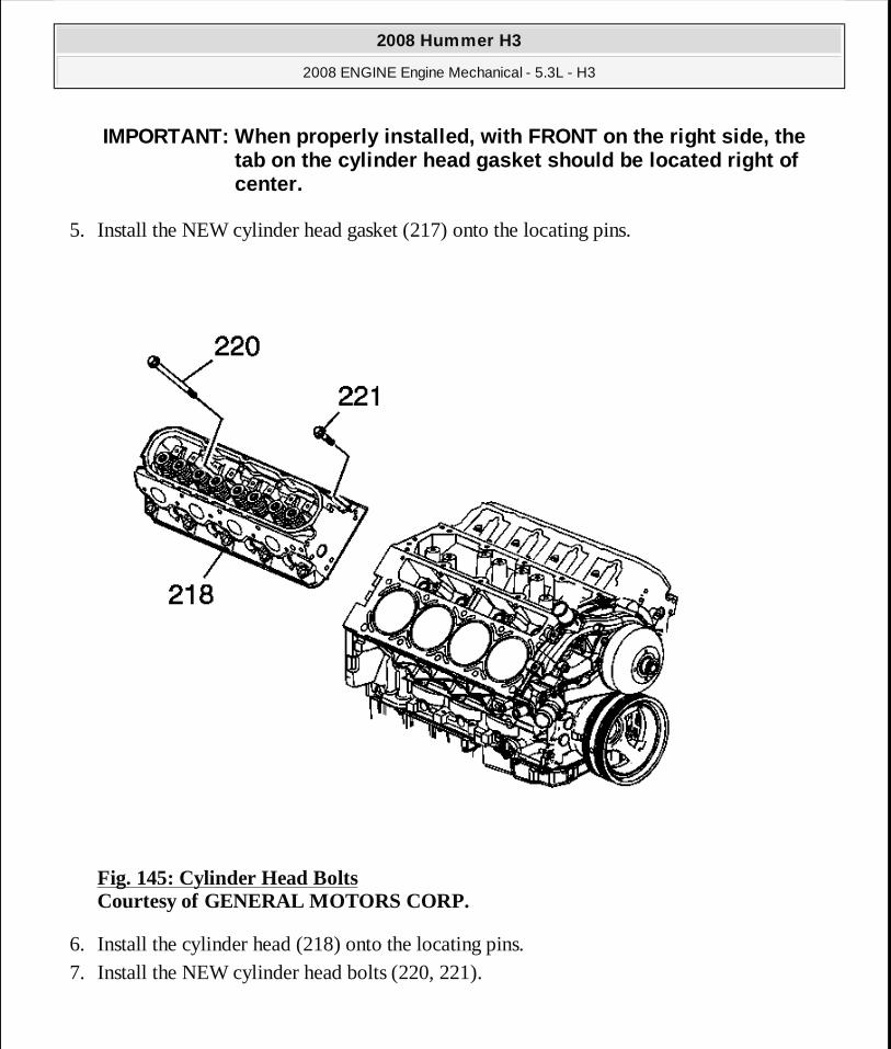
5. Install the NEW cylinder head gasket (217) onto the locating pins.
Fig. 145: Cylinder Head Bolts Courtesy of GENERAL MOTORS CORP.
6. Install the cylinder head (218) onto the locating pins. 7. Install the NEW cylinder head bolts (220, 221).
IMPORTANT: When properly installed, with FRONT on th e right side, the tab on the cylinder head gasket should be located r ight of center.
2008 Hummer H3
2008 ENGINE Engine Mechanical - 5.3L - H3
MY
Sunday, March 29, 2009 10:47:45 PM Page 205 © 2005 Mitchell Repair Information Company, LLC.

Fig. 146: Cylinder Head Bolt Tightening Sequence Courtesy of GENERAL MOTORS CORP.
8. Tighten the cylinder head bolts.
Tighten: 1. Tighten the M11 cylinder head bolts (1-10) a first pass in sequence to 30 N.m (22 lb
ft). 2. Tighten the M11 cylinder head bolts (1-10) a second pass in sequence to 90 degrees
using J 45059 . 3. Tighten the M11 cylinder head bolts (1-10 ) a final pass to 70 degrees in sequence
using J 45059 . 4. Tighten the M8 cylinder head bolts (11-15) to 30 N.m (22 lb ft). Begin with the center
bolt (11) and alternating side-to-side, work outward tightening all of the bolts.
NOTE: Refer to Fastener Notice .
2008 Hummer H3
2008 ENGINE Engine Mechanical - 5.3L - H3
MY
Sunday, March 29, 2009 10:47:45 PM Page 206 © 2005 Mitchell Repair Information Company, LLC.
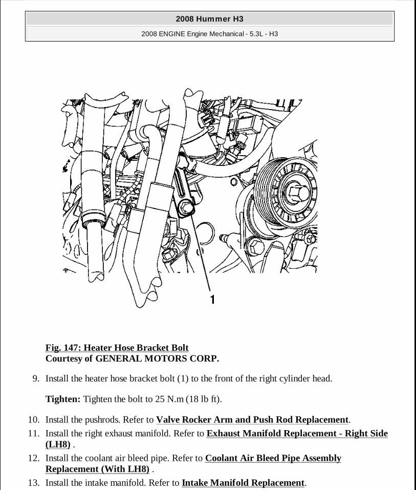
Fig. 147: Heater Hose Bracket Bolt Courtesy of GENERAL MOTORS CORP.
9. Install the heater hose bracket bolt (1) to the front of the right cylinder head.
Tighten: Tighten the bolt to 25 N.m (18 lb ft).
10. Install the pushrods. Refer to Valve Rocker Arm and Push Rod Replacement. 11. Install the right exhaust manifold. Refer to Exhaust Manifold Replacement - Right Side
(LH8) . 12. Install the coolant air bleed pipe. Refer to Coolant Air Bleed Pipe Assembly
Replacement (With LH8) . 13. Install the intake manifold. Refer to Intake Manifold Replacement.
2008 Hummer H3
2008 ENGINE Engine Mechanical - 5.3L - H3
MY
Sunday, March 29, 2009 10:47:45 PM Page 207 © 2005 Mitchell Repair Information Company, LLC.

14. Install the oil level indicator. Refer to Oil Level Indicator and Tube Replacement.
VALVE LIFTER REPLACEMENT
Tools Required
J 3049-A Valve Lifter Remover
Removal Procedure
Fig. 148: View Of Cylinder Head (Left) Courtesy of GENERAL MOTORS CORP.
1. Remove the cylinder head and gasket. Refer to Cylinder Head Replacement - Left Side or to Cylinder Head Replacement - Right Side.
2008 Hummer H3
2008 ENGINE Engine Mechanical - 5.3L - H3
MY
Sunday, March 29, 2009 10:47:45 PM Page 208 © 2005 Mitchell Repair Information Company, LLC.

Fig. 149: View Of Lifter Guides & Lifters Courtesy of GENERAL MOTORS CORP.
2. Remove the valve lifter. Refer to Valve Lifter Removal. 3. Clean and inspect the valve lifters. Refer to Valve Lifter and Guide Cleaning and
Inspection.
Installation Procedure
2008 Hummer H3
2008 ENGINE Engine Mechanical - 5.3L - H3
MY
Sunday, March 29, 2009 10:47:45 PM Page 209 © 2005 Mitchell Repair Information Company, LLC.
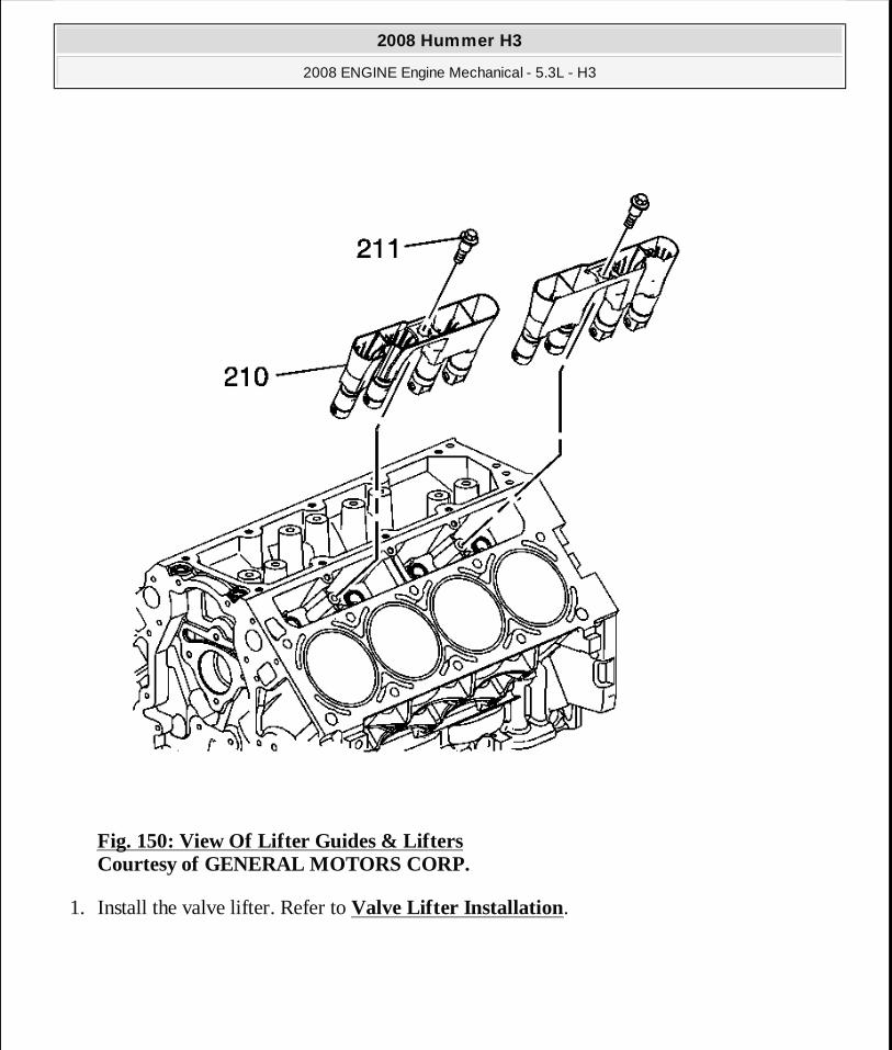
Fig. 150: View Of Lifter Guides & Lifters Courtesy of GENERAL MOTORS CORP.
1. Install the valve lifter. Refer to Valve Lifter Installation.
2008 Hummer H3
2008 ENGINE Engine Mechanical - 5.3L - H3
MY
Sunday, March 29, 2009 10:47:45 PM Page 210 © 2005 Mitchell Repair Information Company, LLC.
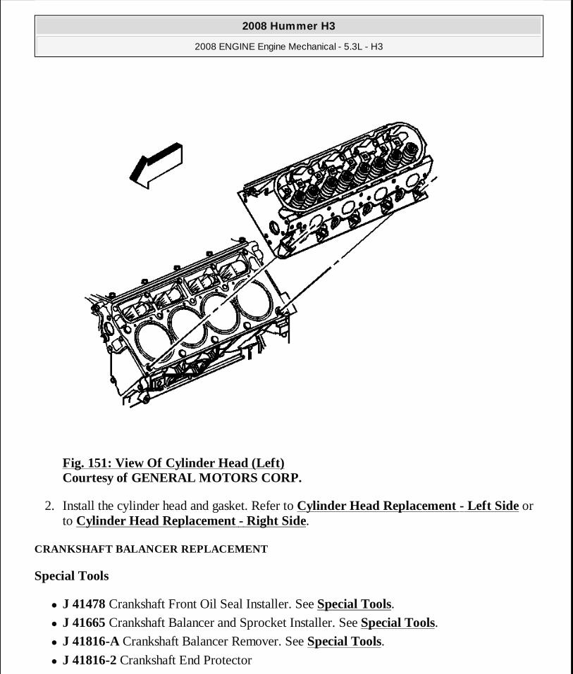
Fig. 151: View Of Cylinder Head (Left) Courtesy of GENERAL MOTORS CORP.
2. Install the cylinder head and gasket. Refer to Cylinder Head Replacement - Left Side or to Cylinder Head Replacement - Right Side.
CRANKSHAFT BALANCER REPLACEMENT
Special Tools
� J 41478 Crankshaft Front Oil Seal Installer. See Special Tools. � J 41665 Crankshaft Balancer and Sprocket Installer. See Special Tools. � J 41816-A Crankshaft Balancer Remover. See Special Tools. � J 41816-2 Crankshaft End Protector
2008 Hummer H3
2008 ENGINE Engine Mechanical - 5.3L - H3
MY
Sunday, March 29, 2009 10:47:45 PM Page 211 © 2005 Mitchell Repair Information Company, LLC.
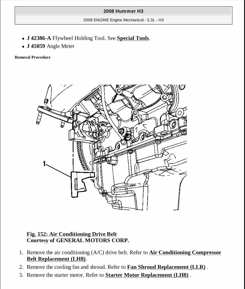
� J 42386-A Flywheel Holding Tool. See Special Tools. � J 45059 Angle Meter
Removal Procedure
Fig. 152: Air Conditioning Drive Belt Courtesy of GENERAL MOTORS CORP.
1. Remove the air conditioning (A/C) drive belt. Refer to Air Conditioning Compressor Belt Replacement (LH8).
2. Remove the cooling fan and shroud. Refer to Fan Shroud Replacement (LLR) . 3. Remove the starter motor. Refer to Starter Motor Replacement (LH8) .
2008 Hummer H3
2008 ENGINE Engine Mechanical - 5.3L - H3
MY
Sunday, March 29, 2009 10:47:45 PM Page 212 © 2005 Mitchell Repair Information Company, LLC.

4. Install the J 42386-A (1) and bolts. See Special Tools. Use one M10-1.5 x 120 mm and one M10-1.5 x 45 mm bolt for proper tool operation.
Tighten: Tighten the J 42386-A bolts to 50 N. See Special Tools.m (37 lb ft).
NOTE: Refer to Fastener Notice .
IMPORTANT: Ensure that the teeth of the J 42386-A me sh with the teeth of the engine flywheel. See Special Tools .
2008 Hummer H3
2008 ENGINE Engine Mechanical - 5.3L - H3
MY
Sunday, March 29, 2009 10:47:45 PM Page 213 © 2005 Mitchell Repair Information Company, LLC.

Fig. 153: Crankshaft Balancer Bolt Courtesy of GENERAL MOTORS CORP.
5. Remove the crankshaft balancer bolt (139). Do not discard the crankshaft balancer bolt at this time. The old balancer bolt will be used during the balancer installation procedure.
2008 Hummer H3
2008 ENGINE Engine Mechanical - 5.3L - H3
MY
Sunday, March 29, 2009 10:47:45 PM Page 214 © 2005 Mitchell Repair Information Company, LLC.

Fig. 154: Removing Crankshaft Balancer Courtesy of GENERAL MOTORS CORP.
6. Install the J 41816 (1) and J 41816-2 (2) to the crankshaft balancer.
2008 Hummer H3
2008 ENGINE Engine Mechanical - 5.3L - H3
MY
Sunday, March 29, 2009 10:47:45 PM Page 215 © 2005 Mitchell Repair Information Company, LLC.
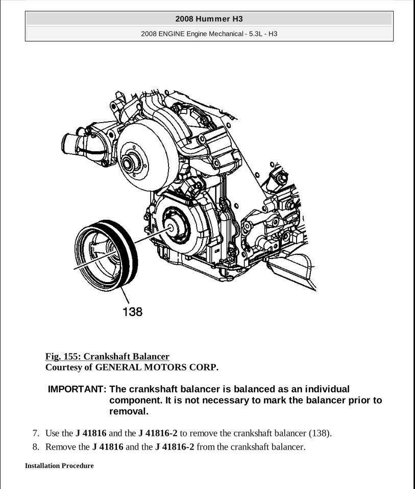
Fig. 155: Crankshaft Balancer Courtesy of GENERAL MOTORS CORP.
7. Use the J 41816 and the J 41816-2 to remove the crankshaft balancer (138).
8. Remove the J 41816 and the J 41816-2 from the crankshaft balancer.
Installation Procedure
IMPORTANT: The crankshaft balancer is balanced as an individual component. It is not necessary to mark the balancer prior to removal.
2008 Hummer H3
2008 ENGINE Engine Mechanical - 5.3L - H3
MY
Sunday, March 29, 2009 10:47:45 PM Page 216 © 2005 Mitchell Repair Information Company, LLC.
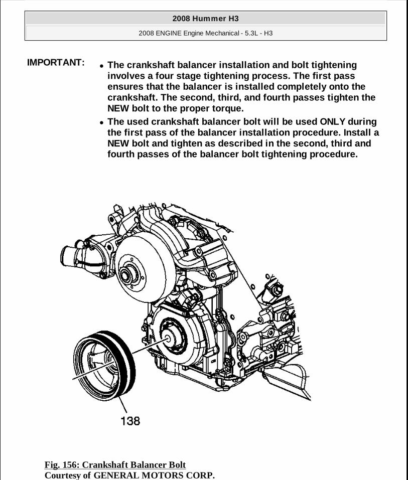
Fig. 156: Crankshaft Balancer Bolt Courtesy of GENERAL MOTORS CORP.
IMPORTANT:� The crankshaft balancer installation and bolt tight ening
involves a four stage tightening process. The first pass ensures that the balancer is installed completely o nto the crankshaft. The second, third, and fourth passes ti ghten the NEW bolt to the proper torque.
� The used crankshaft balancer bolt will be used ONLY during the first pass of the balancer installation procedu re. Install a NEW bolt and tighten as described in the second, th ird and fourth passes of the balancer bolt tightening proce dure.
2008 Hummer H3
2008 ENGINE Engine Mechanical - 5.3L - H3
MY
Sunday, March 29, 2009 10:47:45 PM Page 217 © 2005 Mitchell Repair Information Company, LLC.
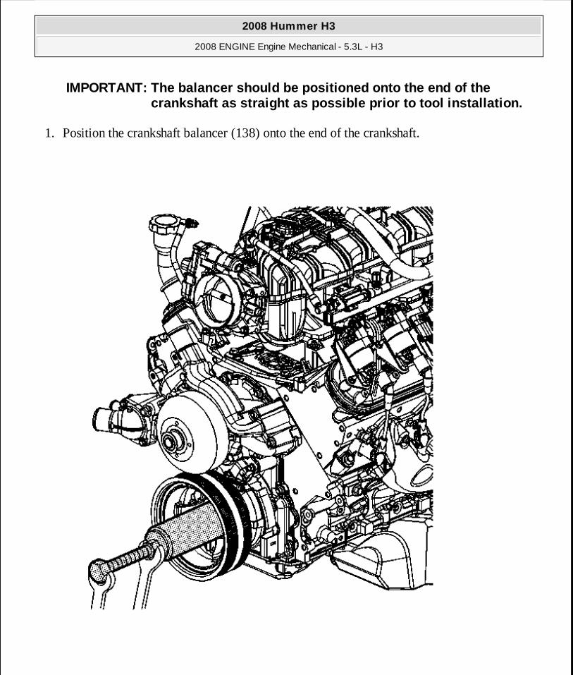
1. Position the crankshaft balancer (138) onto the end of the crankshaft.
IMPORTANT: The balancer should be positioned onto th e end of the crankshaft as straight as possible prior to tool in stallation.
2008 Hummer H3
2008 ENGINE Engine Mechanical - 5.3L - H3
MY
Sunday, March 29, 2009 10:47:45 PM Page 218 © 2005 Mitchell Repair Information Company, LLC.
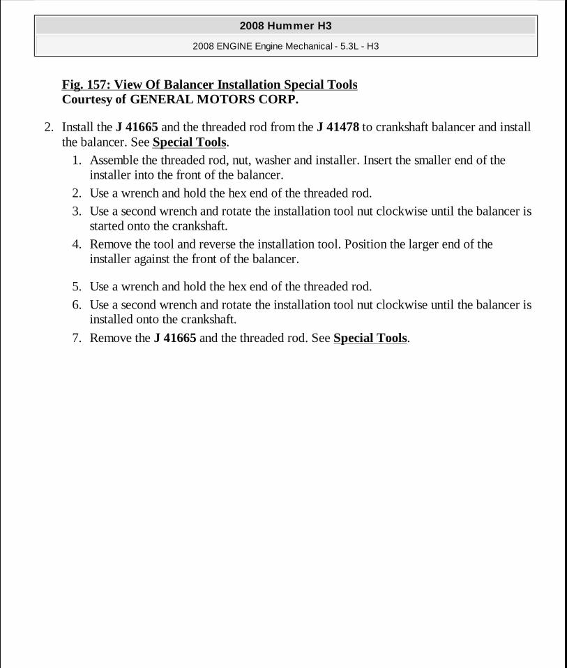
Fig. 157: View Of Balancer Installation Special Tools Courtesy of GENERAL MOTORS CORP.
2. Install the J 41665 and the threaded rod from the J 41478 to crankshaft balancer and install the balancer. See Special Tools.
1. Assemble the threaded rod, nut, washer and installer. Insert the smaller end of the installer into the front of the balancer.
2. Use a wrench and hold the hex end of the threaded rod. 3. Use a second wrench and rotate the installation tool nut clockwise until the balancer is
started onto the crankshaft. 4. Remove the tool and reverse the installation tool. Position the larger end of the
installer against the front of the balancer.
5. Use a wrench and hold the hex end of the threaded rod. 6. Use a second wrench and rotate the installation tool nut clockwise until the balancer is
installed onto the crankshaft.
7. Remove the J 41665 and the threaded rod. See Special Tools.
2008 Hummer H3
2008 ENGINE Engine Mechanical - 5.3L - H3
MY
Sunday, March 29, 2009 10:47:45 PM Page 219 © 2005 Mitchell Repair Information Company, LLC.
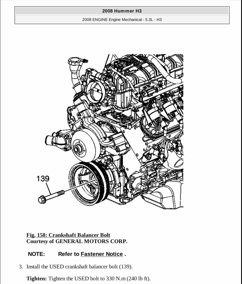
Fig. 158: Crankshaft Balancer Bolt Courtesy of GENERAL MOTORS CORP.
3. Install the USED crankshaft balancer bolt (139).
Tighten: Tighten the USED bolt to 330 N.m (240 lb ft).
NOTE: Refer to Fastener Notice .
2008 Hummer H3
2008 ENGINE Engine Mechanical - 5.3L - H3
MY
Sunday, March 29, 2009 10:47:45 PM Page 220 © 2005 Mitchell Repair Information Company, LLC.
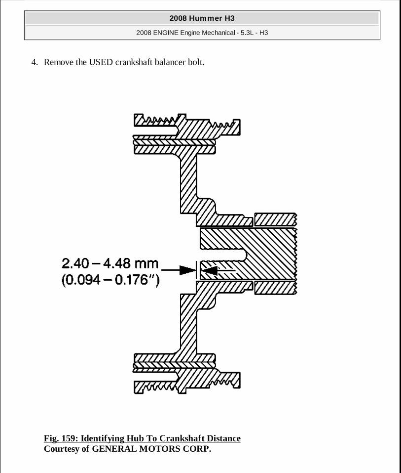
4. Remove the USED crankshaft balancer bolt.
Fig. 159: Identifying Hub To Crankshaft Distance Courtesy of GENERAL MOTORS CORP.
2008 Hummer H3
2008 ENGINE Engine Mechanical - 5.3L - H3
MY
Sunday, March 29, 2009 10:47:45 PM Page 221 © 2005 Mitchell Repair Information Company, LLC.

5. Measure for a correctly installed balancer. If the balancer is not installed to the proper dimension, install the J 41665 and repeat the installation procedure. See Special Tools.
Fig. 160: Crankshaft Balancer Bolt Courtesy of GENERAL MOTORS CORP.
IMPORTANT: The nose of the crankshaft should be rece ssed 2.4-4.48 mm (0.094-0.176 in) into the balancer bore.
2008 Hummer H3
2008 ENGINE Engine Mechanical - 5.3L - H3
MY
Sunday, March 29, 2009 10:47:45 PM Page 222 © 2005 Mitchell Repair Information Company, LLC.
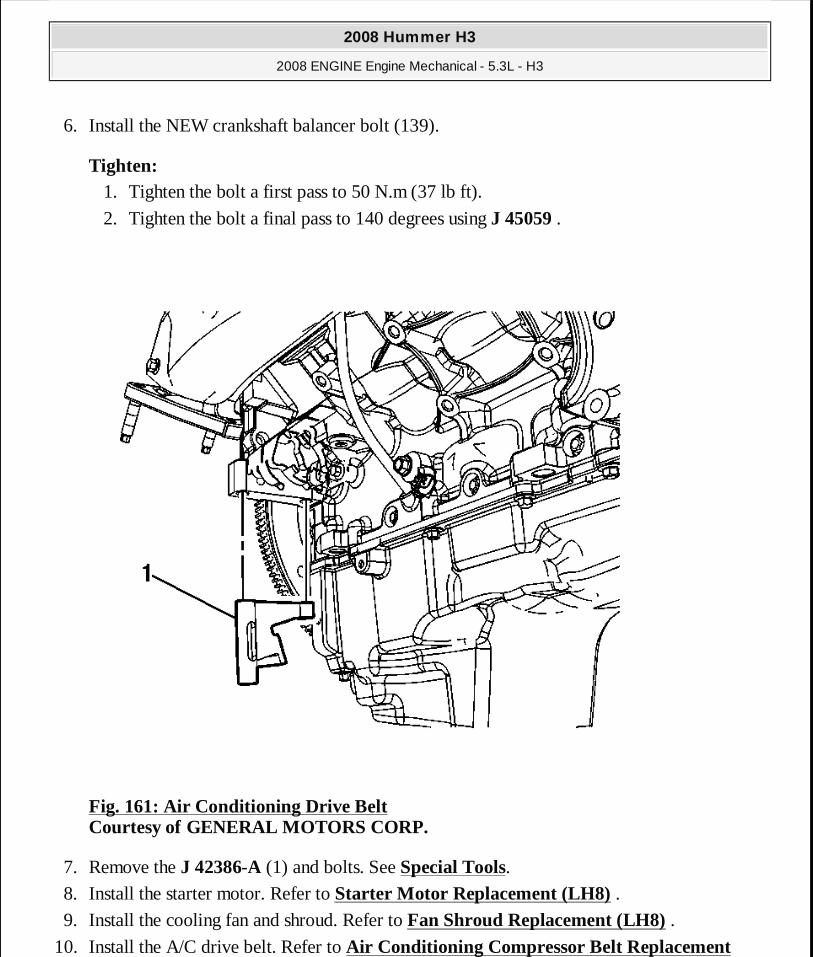
6. Install the NEW crankshaft balancer bolt (139).
Tighten: 1. Tighten the bolt a first pass to 50 N.m (37 lb ft).
2. Tighten the bolt a final pass to 140 degrees using J 45059 .
Fig. 161: Air Conditioning Drive Belt Courtesy of GENERAL MOTORS CORP.
7. Remove the J 42386-A (1) and bolts. See Special Tools. 8. Install the starter motor. Refer to Starter Motor Replacement (LH8) . 9. Install the cooling fan and shroud. Refer to Fan Shroud Replacement (LH8) .
10. Install the A/C drive belt. Refer to Air Conditioning Compressor Belt Replacement
2008 Hummer H3
2008 ENGINE Engine Mechanical - 5.3L - H3
MY
Sunday, March 29, 2009 10:47:45 PM Page 223 © 2005 Mitchell Repair Information Company, LLC.
(LH8). 11. Perform the crankshaft position (CKP) system variation learn procedure. Refer to
Crankshaft Position System Variation Learn .
CRANKSHAFT FRONT OIL SEAL REPLACEMENT
Special Tools
J 41478 Crankshaft Front Oil Seal Installer. See Special Tools.
Removal Procedure
2008 Hummer H3
2008 ENGINE Engine Mechanical - 5.3L - H3
MY
Sunday, March 29, 2009 10:47:45 PM Page 224 © 2005 Mitchell Repair Information Company, LLC.
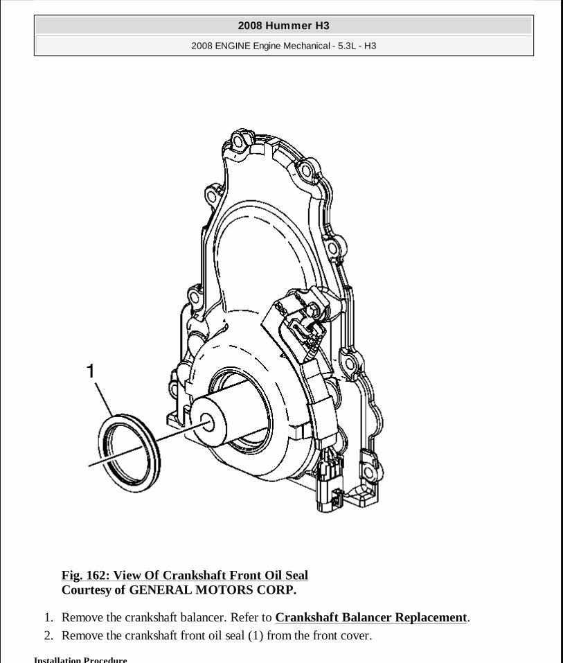
Fig. 162: View Of Crankshaft Front Oil Seal Courtesy of GENERAL MOTORS CORP.
1. Remove the crankshaft balancer. Refer to Crankshaft Balancer Replacement. 2. Remove the crankshaft front oil seal (1) from the front cover.
Installation Procedure
2008 Hummer H3
2008 ENGINE Engine Mechanical - 5.3L - H3
MY
Sunday, March 29, 2009 10:47:45 PM Page 225 © 2005 Mitchell Repair Information Company, LLC.

Fig. 163: View Of Crankshaft Front Oil Seal Courtesy of GENERAL MOTORS CORP.
IMPORTANT:� Do not lubricate the oil seal sealing surface. � Do not reuse the crankshaft front oil seal.
2008 Hummer H3
2008 ENGINE Engine Mechanical - 5.3L - H3
MY
Sunday, March 29, 2009 10:47:45 PM Page 226 © 2005 Mitchell Repair Information Company, LLC.

1. Lubricate the outer edge of the oil seal (1) with clean engine oil. 2. Lubricate the front cover oil seal bore with clean engine oil.
Fig. 164: View Of Crankshaft Front Oil Seal Installation Courtesy of GENERAL MOTORS CORP.
3. Install the crankshaft front oil seal (1) onto the J 41478 guide. See Special Tools. 4. Install the J 41478 threaded rod (with nut, washer, guide, and oil seal) into the end of the
crankshaft. See Special Tools. 5. Use the J 41478 in order to install the oil seal into the cover bore. See Special Tools.
1. Use a wrench and hold the hex on the installer bolt.
2008 Hummer H3
2008 ENGINE Engine Mechanical - 5.3L - H3
MY
Sunday, March 29, 2009 10:47:46 PM Page 227 © 2005 Mitchell Repair Information Company, LLC.
2. Use a second wrench and rotate the installer nut clockwise until the seal bottoms in the cover bore.
3. Remove the J 41478 . See Special Tools. 4. Inspect the oil seal for proper installation. The oil seal should be installed evenly and
completely into the front cover bore.
6. Install the crankshaft balancer. Refer to Crankshaft Balancer Replacement.
ENGINE FRONT COVER REPLACEMENT
Special Tools
� J 41476 Front and Rear Cover Alignment Tool. See Special Tools. � J 41480 Front and Rear Cover Alignment. See Special Tools.
Removal Procedure
2008 Hummer H3
2008 ENGINE Engine Mechanical - 5.3L - H3
MY
Sunday, March 29, 2009 10:47:46 PM Page 228 © 2005 Mitchell Repair Information Company, LLC.
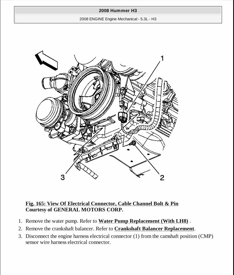
Fig. 165: View Of Electrical Connector, Cable Channel Bolt & Pin Courtesy of GENERAL MOTORS CORP.
1. Remove the water pump. Refer to Water Pump Replacement (With LH8) . 2. Remove the crankshaft balancer. Refer to Crankshaft Balancer Replacement. 3. Disconnect the engine harness electrical connector (1) from the camshaft position (CMP)
sensor wire harness electrical connector.
2008 Hummer H3
2008 ENGINE Engine Mechanical - 5.3L - H3
MY
Sunday, March 29, 2009 10:47:46 PM Page 229 © 2005 Mitchell Repair Information Company, LLC.
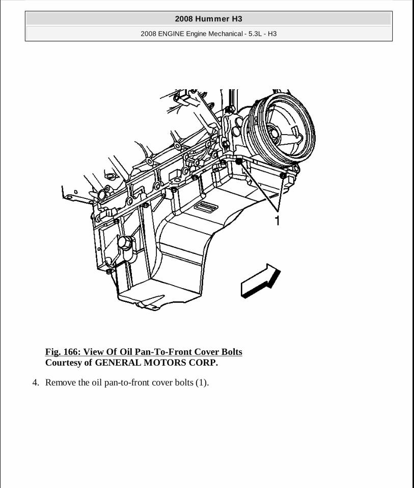
Fig. 166: View Of Oil Pan-To-Front Cover Bolts Courtesy of GENERAL MOTORS CORP.
4. Remove the oil pan-to-front cover bolts (1).
2008 Hummer H3
2008 ENGINE Engine Mechanical - 5.3L - H3
MY
Sunday, March 29, 2009 10:47:46 PM Page 230 © 2005 Mitchell Repair Information Company, LLC.
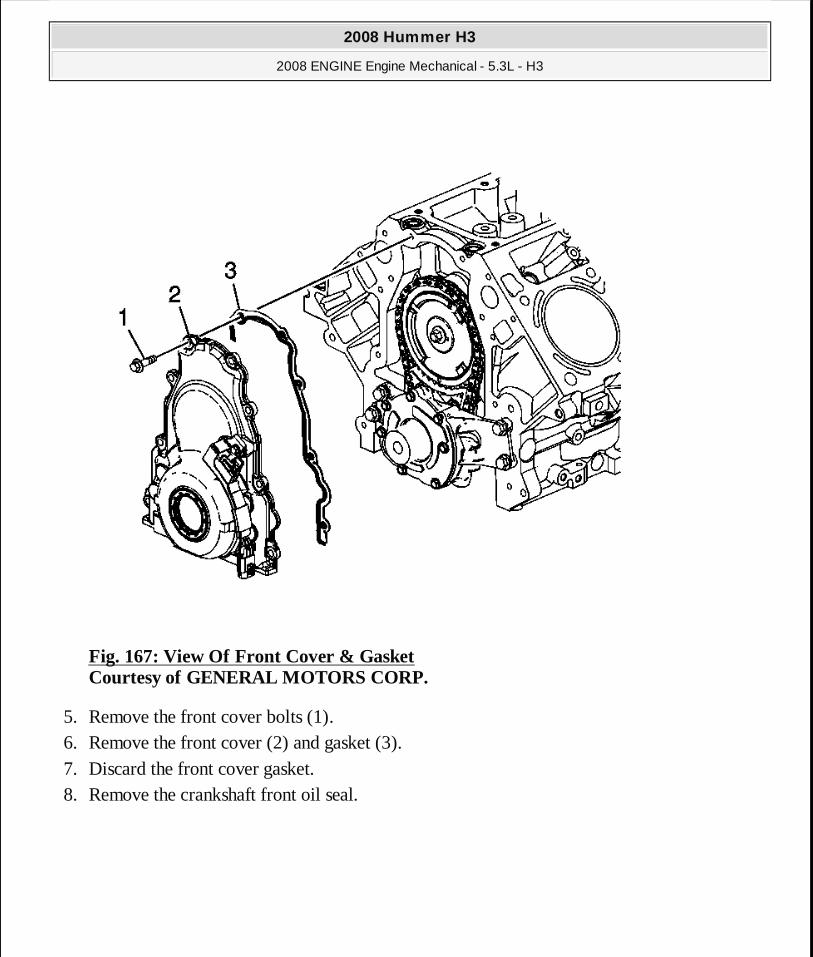
Fig. 167: View Of Front Cover & Gasket Courtesy of GENERAL MOTORS CORP.
5. Remove the front cover bolts (1). 6. Remove the front cover (2) and gasket (3). 7. Discard the front cover gasket. 8. Remove the crankshaft front oil seal.
2008 Hummer H3
2008 ENGINE Engine Mechanical - 5.3L - H3
MY
Sunday, March 29, 2009 10:47:46 PM Page 231 © 2005 Mitchell Repair Information Company, LLC.

Fig. 168: View Of Front Cover, Oil Seal, Camshaft Position Sensor, Bracket & O Ring Courtesy of GENERAL MOTORS CORP.
9. If replacing the engine front cover perform the following steps, otherwise proceed to step 10 of the installation procedure.
2008 Hummer H3
2008 ENGINE Engine Mechanical - 5.3L - H3
MY
Sunday, March 29, 2009 10:47:46 PM Page 232 © 2005 Mitchell Repair Information Company, LLC.
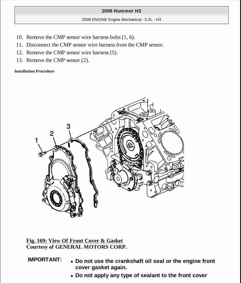
10. Remove the CMP sensor wire harness bolts (1, 6). 11. Disconnect the CMP sensor wire harness from the CMP sensor. 12. Remove the CMP sensor wire harness (5). 13. Remove the CMP sensor (2).
Installation Procedure
Fig. 169: View Of Front Cover & Gasket Courtesy of GENERAL MOTORS CORP.
IMPORTANT:� Do not use the crankshaft oil seal or the engine fr ont
cover gasket again. � Do not apply any type of sealant to the front cover
2008 Hummer H3
2008 ENGINE Engine Mechanical - 5.3L - H3
MY
Sunday, March 29, 2009 10:47:46 PM Page 233 © 2005 Mitchell Repair Information Company, LLC.
1. Install the front cover gasket (3), front cover (2), and bolts (1). 2. Tighten the cover bolts finger tight. Do not overtighten.
gasket, unless specified. � The special tools in this procedure are used to pro perly
align the engine front cover at the oil pan surface and to center the crankshaft front oil seal.
� All gasket surfaces should be free of oil or other foreign material during assembly.
The crankshaft front oil seal MUST be centered in relation to the crankshaft.
� The oil pan sealing surface at the front cover and engine block MUST be aligned within specifications.
� An improperly aligned front cover may cause premature front oil seal wear and/or engine assembly oil leaks.
2008 Hummer H3
2008 ENGINE Engine Mechanical - 5.3L - H3
MY
Sunday, March 29, 2009 10:47:46 PM Page 234 © 2005 Mitchell Repair Information Company, LLC.

Fig. 170: View Of J 41480 Installed On Engine Block Courtesy of GENERAL MOTORS CORP.
NOTE: Refer to Fastener Notice .
IMPORTANT: Start the tool-to-front cover bolts. Do n ot tighten the bolts at this time.
2008 Hummer H3
2008 ENGINE Engine Mechanical - 5.3L - H3
MY
Sunday, March 29, 2009 10:47:46 PM Page 235 © 2005 Mitchell Repair Information Company, LLC.

3. Install the J 41480 . See Special Tools.
Tighten: Tighten the tool-to-engine block bolts to 25 N.m (18 lb ft).
Fig. 171: View Of J 41476 & J 41480 Installed On Engine Courtesy of GENERAL MOTORS CORP.
IMPORTANT: Align the tapered legs of the tool with t he machined
2008 Hummer H3
2008 ENGINE Engine Mechanical - 5.3L - H3
MY
Sunday, March 29, 2009 10:47:46 PM Page 236 © 2005 Mitchell Repair Information Company, LLC.

4. Install the J 41476 . See Special Tools. 5. Install the crankshaft balancer bolt.
Tighten: 1. Tighten the crankshaft balancer bolt by hand until snug. Do not overtighten.
2. Tighten the J 41480 . See Special Tools. 3. Tighten the engine front cover bolts to 25 N.m (18 lb ft).
6. Remove the tools.
alignment surfaces on the front cover.
2008 Hummer H3
2008 ENGINE Engine Mechanical - 5.3L - H3
MY
Sunday, March 29, 2009 10:47:46 PM Page 237 © 2005 Mitchell Repair Information Company, LLC.

Fig. 172: Oil Pan Surface Flatness & Front Cover-To-Engine Block Courtesy of GENERAL MOTORS CORP.
7. Measure the oil pan surface flatness, front cover-to-engine block. 1. Place a straight edge across the engine block and front cover oil pan sealing surfaces.
Avoid contact with the portion of the gasket that protrudes into the oil pan surface.
2008 Hummer H3
2008 ENGINE Engine Mechanical - 5.3L - H3
MY
Sunday, March 29, 2009 10:47:46 PM Page 238 © 2005 Mitchell Repair Information Company, LLC.

2. Insert a feeler gage between the front cover and the straight edge tool. The cover must be flush with the oil pan surface or no greater than 0.5 mm (0.02 in) (a) below flush.
8. If the front cover-to-engine block oil pan surface alignment is not within specifications, repeat the cover alignment procedure.
9. If the correct front cover-to-engine block alignment cannot be obtained, replace the front cover.
2008 Hummer H3
2008 ENGINE Engine Mechanical - 5.3L - H3
MY
Sunday, March 29, 2009 10:47:46 PM Page 239 © 2005 Mitchell Repair Information Company, LLC.

Fig. 173: View Of Front Cover, Oil Seal, Camshaft Position Sensor, Bracket & O Ring Courtesy of GENERAL MOTORS CORP.
10. Inspect the camshaft position (CMP) sensor O-ring seal (3) for cuts or damage. If the seal is not cut or damaged, it may be used again.
2008 Hummer H3
2008 ENGINE Engine Mechanical - 5.3L - H3
MY
Sunday, March 29, 2009 10:47:46 PM Page 240 © 2005 Mitchell Repair Information Company, LLC.
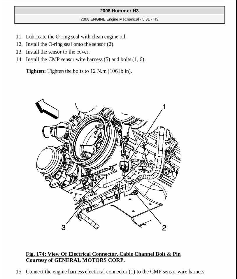
11. Lubricate the O-ring seal with clean engine oil. 12. Install the O-ring seal onto the sensor (2). 13. Install the sensor to the cover. 14. Install the CMP sensor wire harness (5) and bolts (1, 6).
Tighten: Tighten the bolts to 12 N.m (106 lb in).
Fig. 174: View Of Electrical Connector, Cable Channel Bolt & Pin Courtesy of GENERAL MOTORS CORP.
15. Connect the engine harness electrical connector (1) to the CMP sensor wire harness
2008 Hummer H3
2008 ENGINE Engine Mechanical - 5.3L - H3
MY
Sunday, March 29, 2009 10:47:46 PM Page 241 © 2005 Mitchell Repair Information Company, LLC.
electrical connector.
16. Install a NEW crankshaft front oil seal. Refer to Crankshaft Front Oil Seal Replacement.
17. Install the water pump. Refer to Water Pump Replacement (With LH8) .
CRANKSHAFT REAR OIL SEAL REPLACEMENT
Tools Required
J 41479 Crankshaft Rear Oil Seal Installer. See Special Tools.
Removal Procedure
2008 Hummer H3
2008 ENGINE Engine Mechanical - 5.3L - H3
MY
Sunday, March 29, 2009 10:47:46 PM Page 242 © 2005 Mitchell Repair Information Company, LLC.

Fig. 175: Crankshaft Rear Oil Seal & Housing Courtesy of GENERAL MOTORS CORP.
1. Remove the automatic transmission flexplate, refer to Automatic Transmission Flex Plate Replacement.
2. Remove and discard the crankshaft rear oil seal (141).
Installation Procedure
2008 Hummer H3
2008 ENGINE Engine Mechanical - 5.3L - H3
MY
Sunday, March 29, 2009 10:47:46 PM Page 243 © 2005 Mitchell Repair Information Company, LLC.
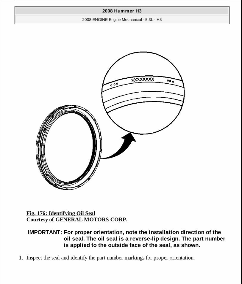
Fig. 176: Identifying Oil Seal Courtesy of GENERAL MOTORS CORP.
1. Inspect the seal and identify the part number markings for proper orientation.
IMPORTANT: For proper orientation, note the installa tion direction of the oil seal. The oil seal is a reverse-lip design. The part number is applied to the outside face of the seal, as show n.
2008 Hummer H3
2008 ENGINE Engine Mechanical - 5.3L - H3
MY
Sunday, March 29, 2009 10:47:46 PM Page 244 © 2005 Mitchell Repair Information Company, LLC.
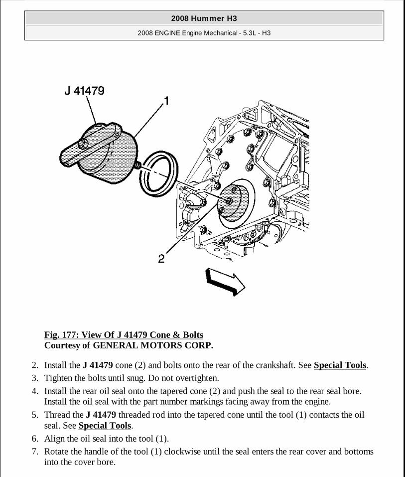
Fig. 177: View Of J 41479 Cone & Bolts Courtesy of GENERAL MOTORS CORP.
2. Install the J 41479 cone (2) and bolts onto the rear of the crankshaft. See Special Tools. 3. Tighten the bolts until snug. Do not overtighten. 4. Install the rear oil seal onto the tapered cone (2) and push the seal to the rear seal bore.
Install the oil seal with the part number markings facing away from the engine.
5. Thread the J 41479 threaded rod into the tapered cone until the tool (1) contacts the oil seal. See Special Tools.
6. Align the oil seal into the tool (1). 7. Rotate the handle of the tool (1) clockwise until the seal enters the rear cover and bottoms
into the cover bore.
2008 Hummer H3
2008 ENGINE Engine Mechanical - 5.3L - H3
MY
Sunday, March 29, 2009 10:47:46 PM Page 245 © 2005 Mitchell Repair Information Company, LLC.
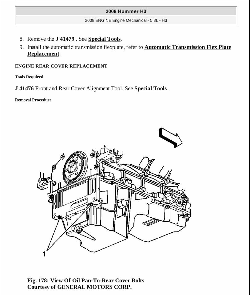
8. Remove the J 41479 . See Special Tools. 9. Install the automatic transmission flexplate, refer to Automatic Transmission Flex Plate
Replacement.
ENGINE REAR COVER REPLACEMENT
Tools Required
J 41476 Front and Rear Cover Alignment Tool. See Special Tools.
Removal Procedure
Fig. 178: View Of Oil Pan-To-Rear Cover Bolts Courtesy of GENERAL MOTORS CORP.
2008 Hummer H3
2008 ENGINE Engine Mechanical - 5.3L - H3
MY
Sunday, March 29, 2009 10:47:46 PM Page 246 © 2005 Mitchell Repair Information Company, LLC.
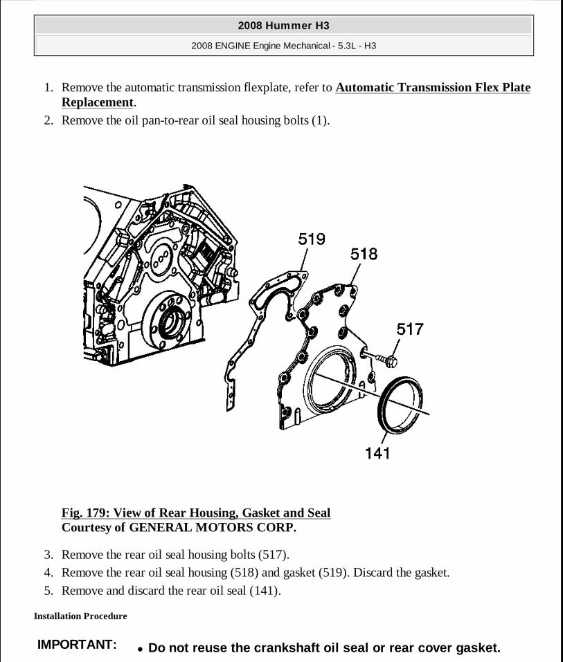
1. Remove the automatic transmission flexplate, refer to Automatic Transmission Flex Plate Replacement.
2. Remove the oil pan-to-rear oil seal housing bolts (1).
Fig. 179: View of Rear Housing, Gasket and Seal Courtesy of GENERAL MOTORS CORP.
3. Remove the rear oil seal housing bolts (517). 4. Remove the rear oil seal housing (518) and gasket (519). Discard the gasket. 5. Remove and discard the rear oil seal (141).
Installation Procedure
IMPORTANT:� Do not reuse the crankshaft oil seal or rear cover gasket.
2008 Hummer H3
2008 ENGINE Engine Mechanical - 5.3L - H3
MY
Sunday, March 29, 2009 10:47:46 PM Page 247 © 2005 Mitchell Repair Information Company, LLC.
� Do not apply any type of sealant to the rear cover gasket, unless specified.
� The special tool in this procedure is used to prope rly center the crankshaft rear oil seal.
� The crankshaft rear oil seal will be installed afte r the rear cover has been installed and aligned. Install the r ear cover without the crankshaft oil seal.
� All gasket surfaces should be free of oil or other foreign material during assembly.
� The crankshaft rear oil seal MUST be centered in relation to the crankshaft.
� An improperly aligned rear cover may cause prematur e rear oil seal wear and/or engine assembly oil leaks .
2008 Hummer H3
2008 ENGINE Engine Mechanical - 5.3L - H3
MY
Sunday, March 29, 2009 10:47:46 PM Page 248 © 2005 Mitchell Repair Information Company, LLC.

Fig. 180: View Of Sealant Applied To Rear Oil Pan-To-Engine Block Junction Courtesy of GENERAL MOTORS CORP.
1. Apply a 5 mm (0.2 in) bead of sealant, 20 mm (0.8 in) long to the oil pan to engine block junction. Refer to Adhesives, Fluids, Lubricants, and Sealers.
2008 Hummer H3
2008 ENGINE Engine Mechanical - 5.3L - H3
MY
Sunday, March 29, 2009 10:47:46 PM Page 249 © 2005 Mitchell Repair Information Company, LLC.
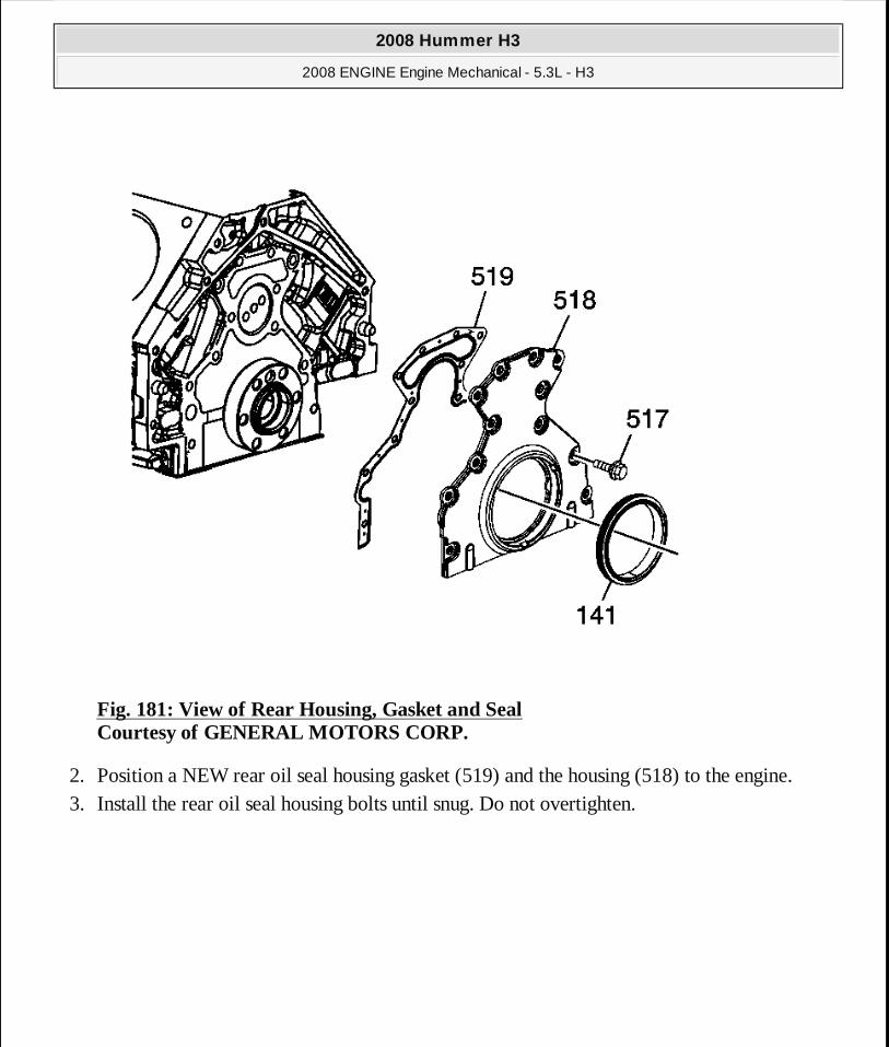
Fig. 181: View of Rear Housing, Gasket and Seal Courtesy of GENERAL MOTORS CORP.
2. Position a NEW rear oil seal housing gasket (519) and the housing (518) to the engine. 3. Install the rear oil seal housing bolts until snug. Do not overtighten.
2008 Hummer H3
2008 ENGINE Engine Mechanical - 5.3L - H3
MY
Sunday, March 29, 2009 10:47:47 PM Page 250 © 2005 Mitchell Repair Information Company, LLC.
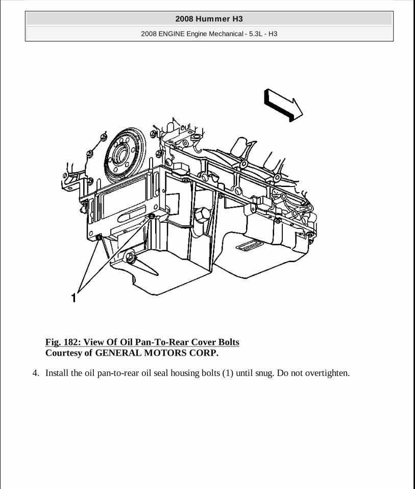
Fig. 182: View Of Oil Pan-To-Rear Cover Bolts Courtesy of GENERAL MOTORS CORP.
4. Install the oil pan-to-rear oil seal housing bolts (1) until snug. Do not overtighten.
2008 Hummer H3
2008 ENGINE Engine Mechanical - 5.3L - H3
MY
Sunday, March 29, 2009 10:47:47 PM Page 251 © 2005 Mitchell Repair Information Company, LLC.
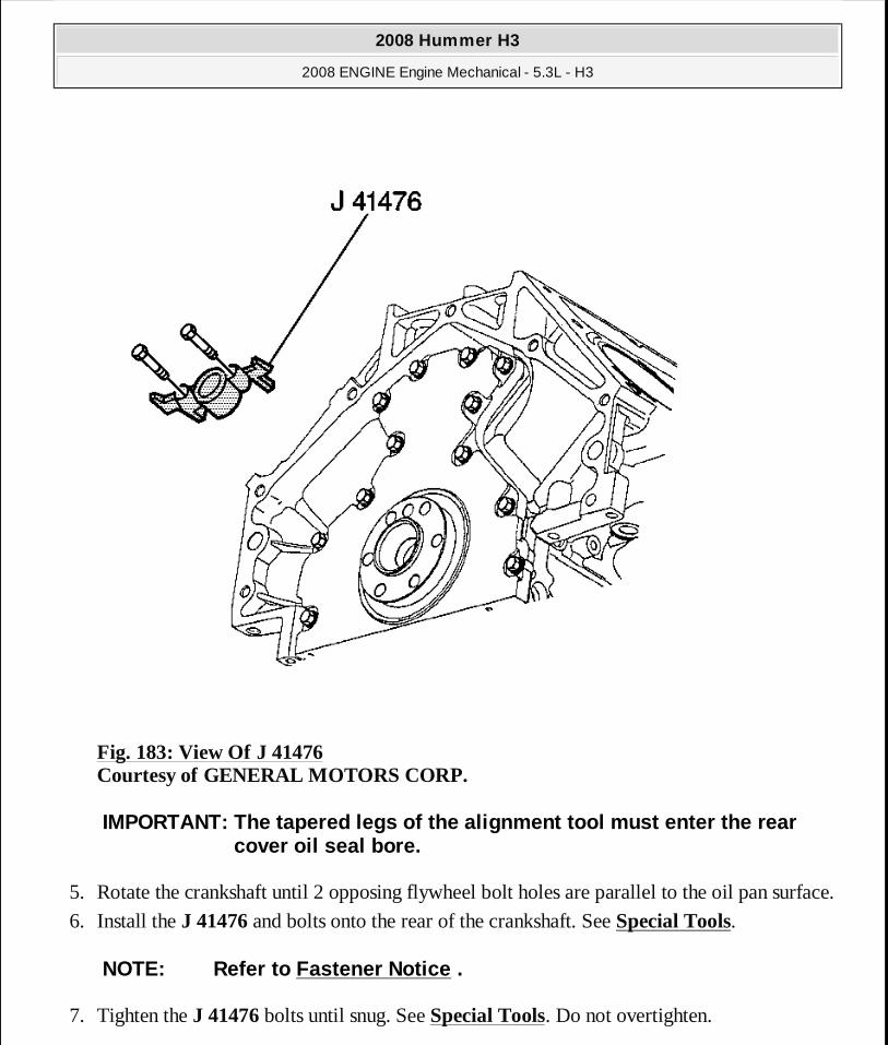
Fig. 183: View Of J 41476 Courtesy of GENERAL MOTORS CORP.
5. Rotate the crankshaft until 2 opposing flywheel bolt holes are parallel to the oil pan surface.
6. Install the J 41476 and bolts onto the rear of the crankshaft. See Special Tools.
7. Tighten the J 41476 bolts until snug. See Special Tools. Do not overtighten.
IMPORTANT: The tapered legs of the alignment tool mu st enter the rear cover oil seal bore.
NOTE: Refer to Fastener Notice .
2008 Hummer H3
2008 ENGINE Engine Mechanical - 5.3L - H3
MY
Sunday, March 29, 2009 10:47:47 PM Page 252 © 2005 Mitchell Repair Information Company, LLC.
Tighten: 1. Tighten the oil pan-to-rear oil seal housing bolts to 12 N.m (106 lb in). 2. Tighten the rear oil seal housing bolts to 30 N.m (22 lb ft).
8. Remove the J 41476 . See Special Tools. 9. Install a NEW crankshaft rear oil seal. Refer to Crankshaft Rear Oil Seal Replacement.
10. Remove the automatic transmission flexplate, refer to Automatic Transmission Flex Plate Replacement.
OIL FILTER ADAPTER REPLACEMENT
Removal Procedure
2008 Hummer H3
2008 ENGINE Engine Mechanical - 5.3L - H3
MY
Sunday, March 29, 2009 10:47:47 PM Page 253 © 2005 Mitchell Repair Information Company, LLC.
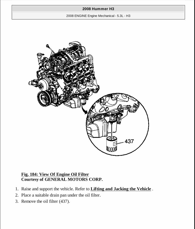
Fig. 184: View Of Engine Oil Filter Courtesy of GENERAL MOTORS CORP.
1. Raise and support the vehicle. Refer to Lifting and Jacking the Vehicle . 2. Place a suitable drain pan under the oil filter. 3. Remove the oil filter (437).
2008 Hummer H3
2008 ENGINE Engine Mechanical - 5.3L - H3
MY
Sunday, March 29, 2009 10:47:47 PM Page 254 © 2005 Mitchell Repair Information Company, LLC.
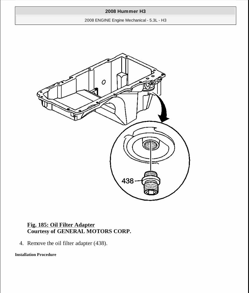
Fig. 185: Oil Filter Adapter Courtesy of GENERAL MOTORS CORP.
4. Remove the oil filter adapter (438).
Installation Procedure
2008 Hummer H3
2008 ENGINE Engine Mechanical - 5.3L - H3
MY
Sunday, March 29, 2009 10:47:47 PM Page 255 © 2005 Mitchell Repair Information Company, LLC.
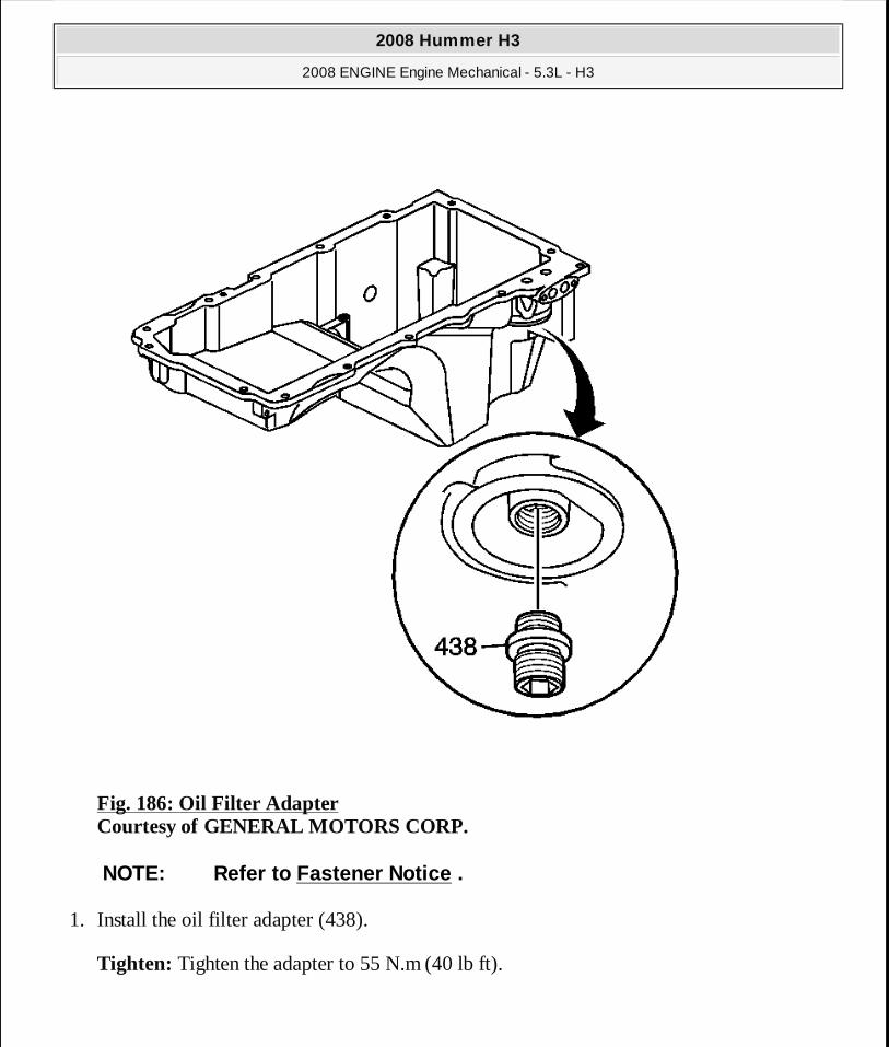
Fig. 186: Oil Filter Adapter Courtesy of GENERAL MOTORS CORP.
1. Install the oil filter adapter (438).
Tighten: Tighten the adapter to 55 N.m (40 lb ft).
NOTE: Refer to Fastener Notice .
2008 Hummer H3
2008 ENGINE Engine Mechanical - 5.3L - H3
MY
Sunday, March 29, 2009 10:47:47 PM Page 256 © 2005 Mitchell Repair Information Company, LLC.
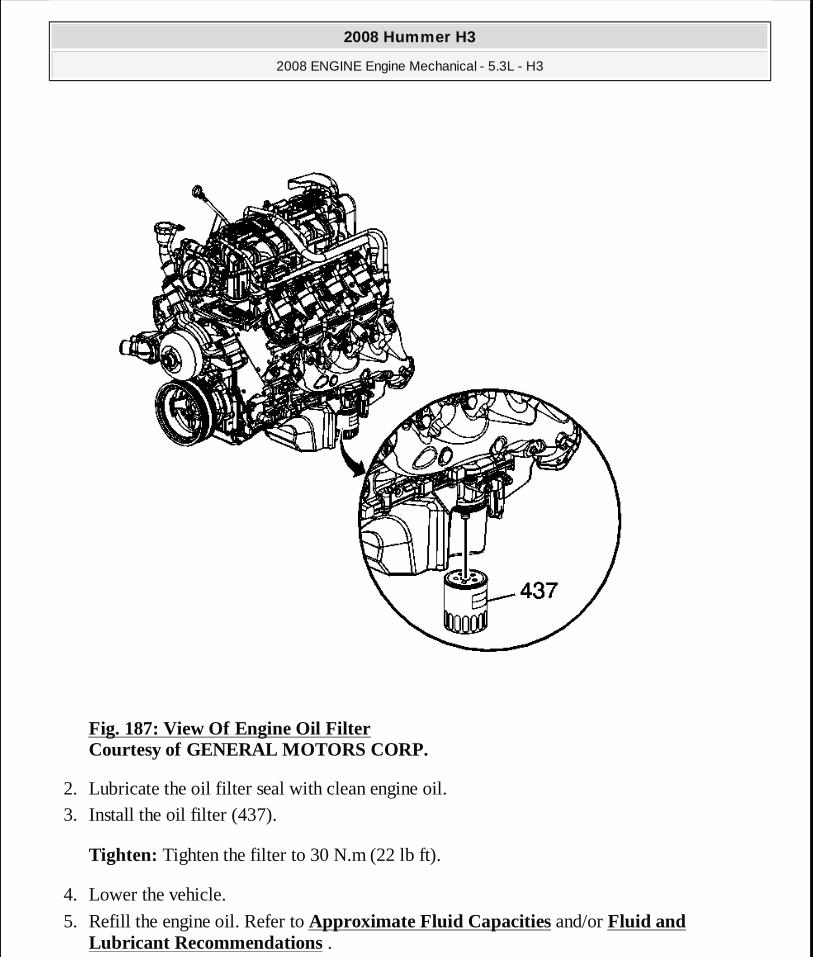
Fig. 187: View Of Engine Oil Filter Courtesy of GENERAL MOTORS CORP.
2. Lubricate the oil filter seal with clean engine oil. 3. Install the oil filter (437).
Tighten: Tighten the filter to 30 N.m (22 lb ft).
4. Lower the vehicle.
5. Refill the engine oil. Refer to Approximate Fluid Capacities and/or Fluid and Lubricant Recommendations .
2008 Hummer H3
2008 ENGINE Engine Mechanical - 5.3L - H3
MY
Sunday, March 29, 2009 10:47:47 PM Page 257 © 2005 Mitchell Repair Information Company, LLC.
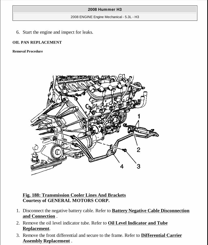
6. Start the engine and inspect for leaks.
OIL PAN REPLACEMENT
Removal Procedure
Fig. 188: Transmission Cooler Lines And Brackets Courtesy of GENERAL MOTORS CORP.
1. Disconnect the negative battery cable. Refer to Battery Negative Cable Disconnection and Connection .
2. Remove the oil level indicator tube. Refer to Oil Level Indicator and Tube Replacement.
3. Remove the front differential and secure to the frame. Refer to Differential Carrier Assembly Replacement .
2008 Hummer H3
2008 ENGINE Engine Mechanical - 5.3L - H3
MY
Sunday, March 29, 2009 10:47:47 PM Page 258 © 2005 Mitchell Repair Information Company, LLC.

4. Drain the engine oil. Refer to Engine Oil and Oil Filter Replacement. 5. Remove the transmission oil cooler lines (1) from the retainer (2). 6. Remove the transmission oil cooler line retaining bracket bolt (3) and bracket (4).
7. Remove the inner axle shaft. Refer to Front Drive Axle Inner Shaft and Inner Shaft Housing Replacement .
8. Remove the starter. Refer to Starter Motor Replacement (LH8) . 9. Remove the flywheel inspection cover from the left side of the transmission.
Fig. 189: View Of Battery Cable Channel & Bolt Courtesy of GENERAL MOTORS CORP.
10. Remove the battery cable channel bolt from the front of the oil pan. 11. Remove the battery cable channel from the oil pan.
2008 Hummer H3
2008 ENGINE Engine Mechanical - 5.3L - H3
MY
Sunday, March 29, 2009 10:47:47 PM Page 259 © 2005 Mitchell Repair Information Company, LLC.
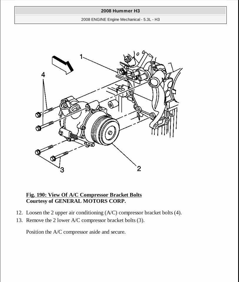
Fig. 190: View Of A/C Compressor Bracket Bolts Courtesy of GENERAL MOTORS CORP.
12. Loosen the 2 upper air conditioning (A/C) compressor bracket bolts (4). 13. Remove the 2 lower A/C compressor bracket bolts (3).
Position the A/C compressor aside and secure.
2008 Hummer H3
2008 ENGINE Engine Mechanical - 5.3L - H3
MY
Sunday, March 29, 2009 10:47:47 PM Page 260 © 2005 Mitchell Repair Information Company, LLC.
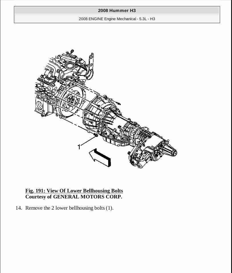
Fig. 191: View Of Lower Bellhousing Bolts Courtesy of GENERAL MOTORS CORP.
14. Remove the 2 lower bellhousing bolts (1).
2008 Hummer H3
2008 ENGINE Engine Mechanical - 5.3L - H3
MY
Sunday, March 29, 2009 10:47:47 PM Page 261 © 2005 Mitchell Repair Information Company, LLC.
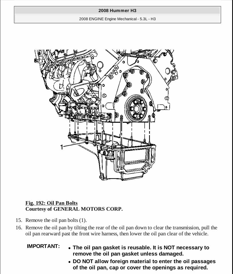
Fig. 192: Oil Pan Bolts Courtesy of GENERAL MOTORS CORP.
15. Remove the oil pan bolts (1). 16. Remove the oil pan by tilting the rear of the oil pan down to clear the transmission, pull the
oil pan rearward past the front wire harness, then lower the oil pan clear of the vehicle.
IMPORTANT:� The oil pan gasket is reusable. It is NOT necessary to
remove the oil pan gasket unless damaged. � DO NOT allow foreign material to enter the oil pass ages
of the oil pan, cap or cover the openings as requir ed.
2008 Hummer H3
2008 ENGINE Engine Mechanical - 5.3L - H3
MY
Sunday, March 29, 2009 10:47:47 PM Page 262 © 2005 Mitchell Repair Information Company, LLC.
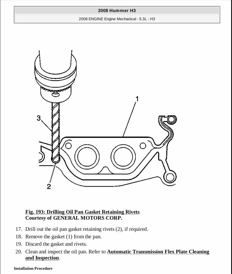
Fig. 193: Drilling Oil Pan Gasket Retaining Rivets Courtesy of GENERAL MOTORS CORP.
17. Drill out the oil pan gasket retaining rivets (2), if required. 18. Remove the gasket (1) from the pan. 19. Discard the gasket and rivets.
20. Clean and inspect the oil pan. Refer to Automatic Transmission Flex Plate Cleaning and Inspection.
Installation Procedure
2008 Hummer H3
2008 ENGINE Engine Mechanical - 5.3L - H3
MY
Sunday, March 29, 2009 10:47:47 PM Page 263 © 2005 Mitchell Repair Information Company, LLC.
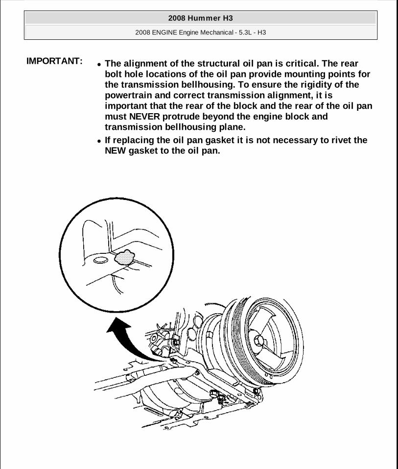
IMPORTANT:� The alignment of the structural oil pan is critical . The rear
bolt hole locations of the oil pan provide mounting points for the transmission bellhousing. To ensure the rigidit y of the powertrain and correct transmission alignment, it i s important that the rear of the block and the rear o f the oil pan must NEVER protrude beyond the engine block and transmission bellhousing plane.
� If replacing the oil pan gasket it is not necessary to rivet the NEW gasket to the oil pan.
2008 Hummer H3
2008 ENGINE Engine Mechanical - 5.3L - H3
MY
Sunday, March 29, 2009 10:47:47 PM Page 264 © 2005 Mitchell Repair Information Company, LLC.

Fig. 194: View Of Sealant Applied To Front Oil Pan-To-Engine Block Junction Courtesy of GENERAL MOTORS CORP.
1. Apply a 5 mm (0.2 in) bead of sealant 20 mm (0.8 in) long to the engine block. Refer to Adhesives, Fluids, Lubricants, and Sealers for the correct part number. Apply the sealant directly onto the tabs of the front cover gasket that protrudes into the oil pan surface.
Fig. 195: View Of Sealant Applied To Rear Oil Pan-To-Engine Block Junction Courtesy of GENERAL MOTORS CORP.
2. Apply a 5 mm (0.2 in) bead of sealant 20 mm (0.8 in) long to the engine block. Refer to Adhesives, Fluids, Lubricants, and Sealers for the correct part number. Apply the sealant
2008 Hummer H3
2008 ENGINE Engine Mechanical - 5.3L - H3
MY
Sunday, March 29, 2009 10:47:47 PM Page 265 © 2005 Mitchell Repair Information Company, LLC.

directly onto the tabs of the rear cover gasket that protrudes into the oil pan surface.
Fig. 196: Oil Pan Bolts Courtesy of GENERAL MOTORS CORP.
3. Pre-assemble the oil pan gasket and bolts (1) to the pan. � Install the gasket onto the pan. � Install the oil pan bolts to the pan and through the gasket.
4. Install the oil pan, oil pan gasket, and bolts to the engine block as an assembly. 5. Hand thread the oil pan bolts into the engine block until snug. Do not tighten at this time.
2008 Hummer H3
2008 ENGINE Engine Mechanical - 5.3L - H3
MY
Sunday, March 29, 2009 10:47:47 PM Page 266 © 2005 Mitchell Repair Information Company, LLC.
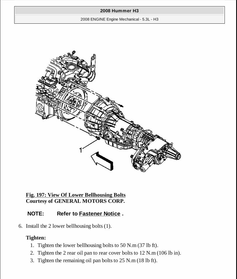
Fig. 197: View Of Lower Bellhousing Bolts Courtesy of GENERAL MOTORS CORP.
6. Install the 2 lower bellhousing bolts (1).
Tighten: 1. Tighten the lower bellhousing bolts to 50 N.m (37 lb ft). 2. Tighten the 2 rear oil pan to rear cover bolts to 12 N.m (106 lb in). 3. Tighten the remaining oil pan bolts to 25 N.m (18 lb ft).
NOTE: Refer to Fastener Notice .
2008 Hummer H3
2008 ENGINE Engine Mechanical - 5.3L - H3
MY
Sunday, March 29, 2009 10:47:47 PM Page 267 © 2005 Mitchell Repair Information Company, LLC.
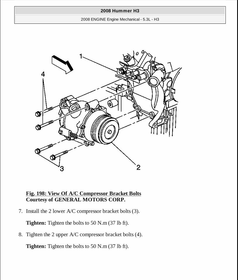
Fig. 198: View Of A/C Compressor Bracket Bolts Courtesy of GENERAL MOTORS CORP.
7. Install the 2 lower A/C compressor bracket bolts (3).
Tighten: Tighten the bolts to 50 N.m (37 lb ft).
8. Tighten the 2 upper A/C compressor bracket bolts (4).
Tighten: Tighten the bolts to 50 N.m (37 lb ft).
2008 Hummer H3
2008 ENGINE Engine Mechanical - 5.3L - H3
MY
Sunday, March 29, 2009 10:47:47 PM Page 268 © 2005 Mitchell Repair Information Company, LLC.

Fig. 199: View Of Battery Cable Channel & Bolt Courtesy of GENERAL MOTORS CORP.
9. Install the battery cable channel to the oil pan. 10. Install the battery cable channel bolt to the oil pan.
Tighten: Tighten the bolt to 12 N.m (106 lb in).
11. Install the flywheel inspection cover to the left side of the transmission.
2008 Hummer H3
2008 ENGINE Engine Mechanical - 5.3L - H3
MY
Sunday, March 29, 2009 10:47:47 PM Page 269 © 2005 Mitchell Repair Information Company, LLC.
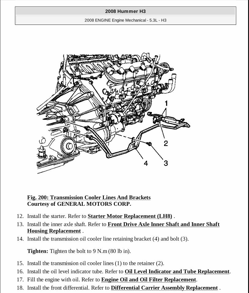
Fig. 200: Transmission Cooler Lines And Brackets Courtesy of GENERAL MOTORS CORP.
12. Install the starter. Refer to Starter Motor Replacement (LH8) . 13. Install the inner axle shaft. Refer to Front Drive Axle Inner Shaft and Inner Shaft
Housing Replacement . 14. Install the transmission oil cooler line retaining bracket (4) and bolt (3).
Tighten: Tighten the bolt to 9 N.m (80 lb in).
15. Install the transmission oil cooler lines (1) to the retainer (2).
16. Install the oil level indicator tube. Refer to Oil Level Indicator and Tube Replacement. 17. Fill the engine with oil. Refer to Engine Oil and Oil Filter Replacement. 18. Install the front differential. Refer to Differential Carrier Assembly Replacement .
2008 Hummer H3
2008 ENGINE Engine Mechanical - 5.3L - H3
MY
Sunday, March 29, 2009 10:47:47 PM Page 270 © 2005 Mitchell Repair Information Company, LLC.
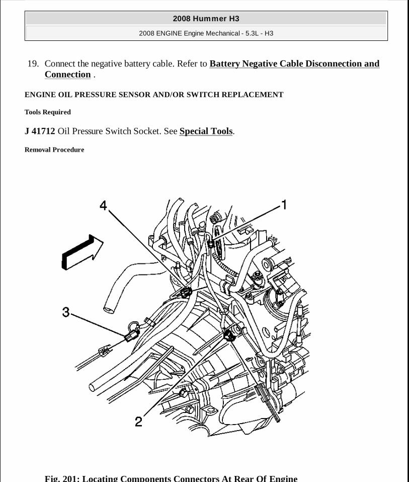
19. Connect the negative battery cable. Refer to Battery Negative Cable Disconnection and Connection .
ENGINE OIL PRESSURE SENSOR AND/OR SWITCH REPLACEMENT
Tools Required
J 41712 Oil Pressure Switch Socket. See Special Tools.
Removal Procedure
Fig. 201: Locating Components Connectors At Rear Of Engine
2008 Hummer H3
2008 ENGINE Engine Mechanical - 5.3L - H3
MY
Sunday, March 29, 2009 10:47:47 PM Page 271 © 2005 Mitchell Repair Information Company, LLC.

Courtesy of GENERAL MOTORS CORP.
1. Remove the intake manifold. Refer to Intake Manifold Replacement. 2. Disconnect the oil pressure sensor electrical connector (1).
Fig. 202: View Of Oil Pressure Sensor & J 41712 Courtesy of GENERAL MOTORS CORP.
3. Using J 41712 or equivalent, remove the oil pressure sensor. See Special Tools.
Installation Procedure
2008 Hummer H3
2008 ENGINE Engine Mechanical - 5.3L - H3
MY
Sunday, March 29, 2009 10:47:47 PM Page 272 © 2005 Mitchell Repair Information Company, LLC.
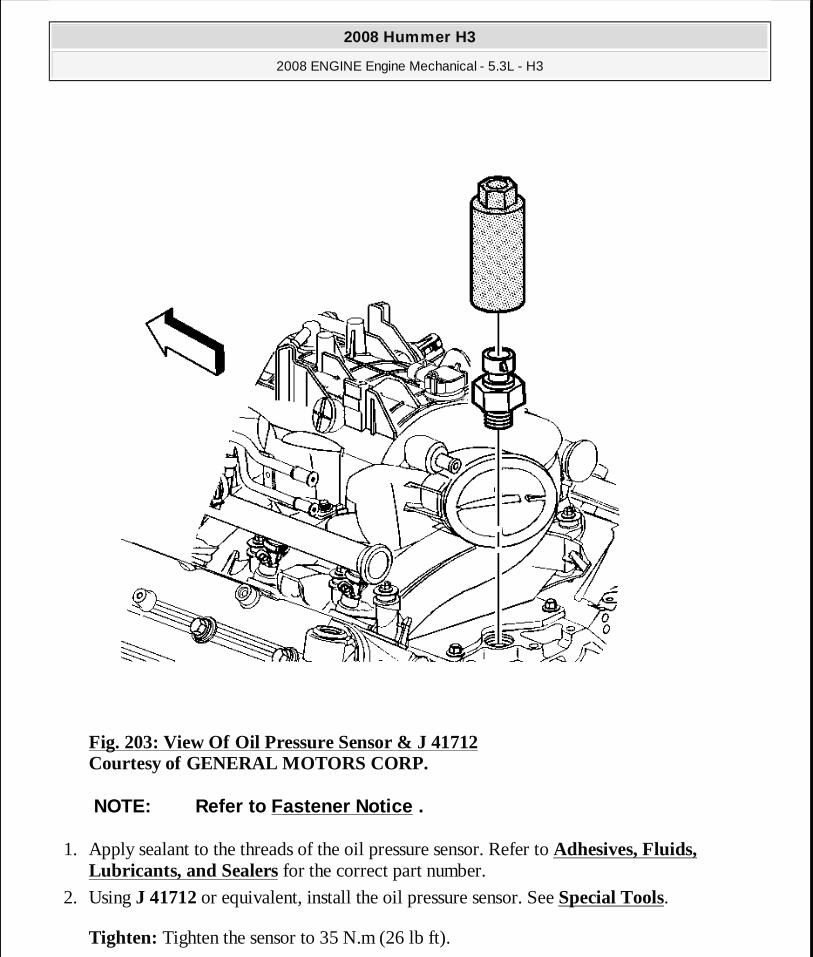
Fig. 203: View Of Oil Pressure Sensor & J 41712 Courtesy of GENERAL MOTORS CORP.
1. Apply sealant to the threads of the oil pressure sensor. Refer to Adhesives, Fluids, Lubricants, and Sealers for the correct part number.
2. Using J 41712 or equivalent, install the oil pressure sensor. See Special Tools.
Tighten: Tighten the sensor to 35 N.m (26 lb ft).
NOTE: Refer to Fastener Notice .
2008 Hummer H3
2008 ENGINE Engine Mechanical - 5.3L - H3
MY
Sunday, March 29, 2009 10:47:48 PM Page 273 © 2005 Mitchell Repair Information Company, LLC.
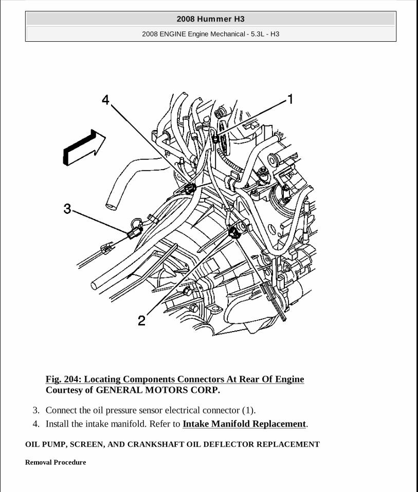
Fig. 204: Locating Components Connectors At Rear Of Engine Courtesy of GENERAL MOTORS CORP.
3. Connect the oil pressure sensor electrical connector (1).
4. Install the intake manifold. Refer to Intake Manifold Replacement.
OIL PUMP, SCREEN, AND CRANKSHAFT OIL DEFLECTOR REPLACEMENT
Removal Procedure
2008 Hummer H3
2008 ENGINE Engine Mechanical - 5.3L - H3
MY
Sunday, March 29, 2009 10:47:48 PM Page 274 © 2005 Mitchell Repair Information Company, LLC.
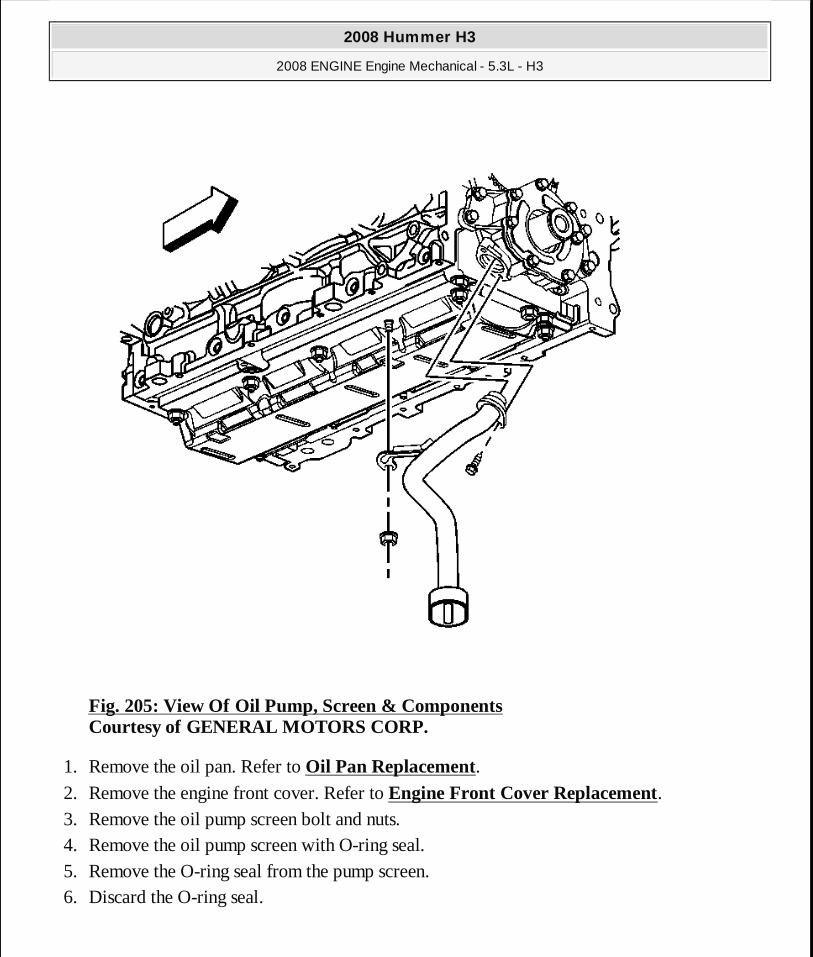
Fig. 205: View Of Oil Pump, Screen & Components Courtesy of GENERAL MOTORS CORP.
1. Remove the oil pan. Refer to Oil Pan Replacement. 2. Remove the engine front cover. Refer to Engine Front Cover Replacement. 3. Remove the oil pump screen bolt and nuts. 4. Remove the oil pump screen with O-ring seal. 5. Remove the O-ring seal from the pump screen. 6. Discard the O-ring seal.
2008 Hummer H3
2008 ENGINE Engine Mechanical - 5.3L - H3
MY
Sunday, March 29, 2009 10:47:48 PM Page 275 © 2005 Mitchell Repair Information Company, LLC.

Fig. 206: View Of Crankshaft Oil Deflector & Nuts Courtesy of GENERAL MOTORS CORP.
7. Remove the remaining crankshaft oil deflector nuts. 8. Remove the crankshaft oil deflector.
2008 Hummer H3
2008 ENGINE Engine Mechanical - 5.3L - H3
MY
Sunday, March 29, 2009 10:47:48 PM Page 276 © 2005 Mitchell Repair Information Company, LLC.

Fig. 207: Removing/Installing Oil Pump Bolts Courtesy of GENERAL MOTORS CORP.
9. Remove the oil pump bolts.
10. Remove the oil pump.
11. Clean and inspect the oil pump. Refer to Oil Pump Cleaning and Inspection.
Installation Procedure
IMPORTANT: Do not allow dirt or debris to enter the oil pump assembly, cap end as necessary.
2008 Hummer H3
2008 ENGINE Engine Mechanical - 5.3L - H3
MY
Sunday, March 29, 2009 10:47:48 PM Page 277 © 2005 Mitchell Repair Information Company, LLC.

Fig. 208: Locating Oil Pump Bolts Courtesy of GENERAL MOTORS CORP.
1. Align the splined surfaces of the crankshaft sprocket and the oil pump drive gear and install the oil pump.
2. Install the oil pump onto the crankshaft sprocket until the pump housing contacts the face of the engine block.
3. Install the oil pump bolts.
NOTE: Refer to Fastener Notice .
2008 Hummer H3
2008 ENGINE Engine Mechanical - 5.3L - H3
MY
Sunday, March 29, 2009 10:47:48 PM Page 278 © 2005 Mitchell Repair Information Company, LLC.
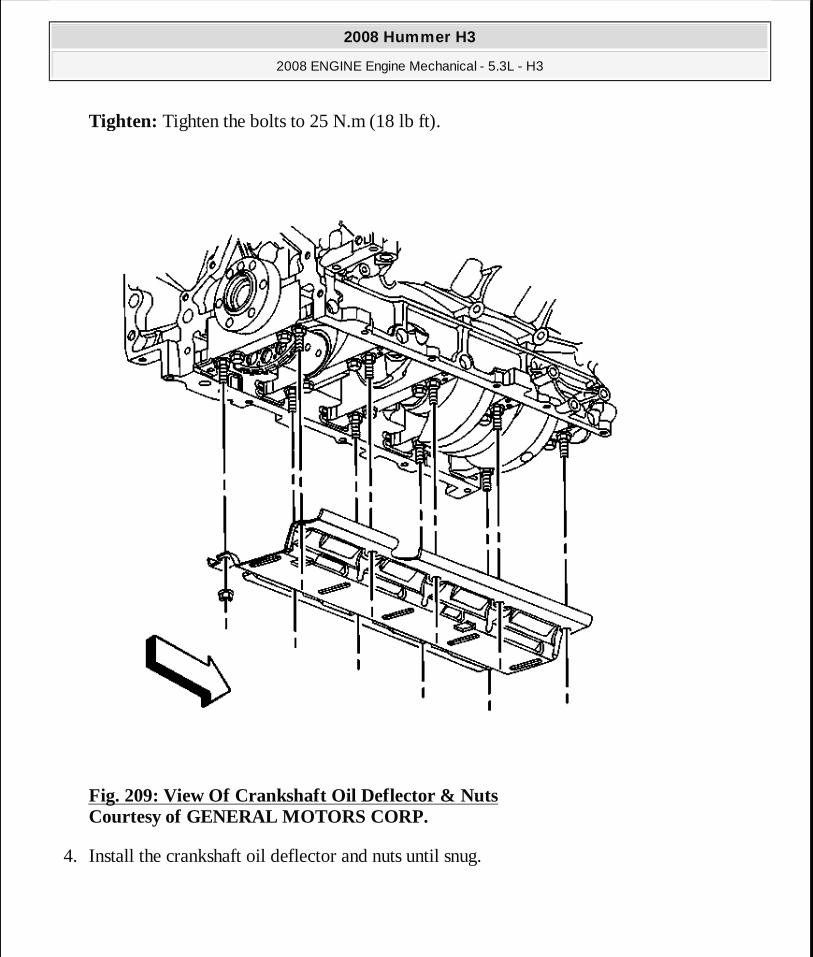
Tighten: Tighten the bolts to 25 N.m (18 lb ft).
Fig. 209: View Of Crankshaft Oil Deflector & Nuts Courtesy of GENERAL MOTORS CORP.
4. Install the crankshaft oil deflector and nuts until snug.
2008 Hummer H3
2008 ENGINE Engine Mechanical - 5.3L - H3
MY
Sunday, March 29, 2009 10:47:48 PM Page 279 © 2005 Mitchell Repair Information Company, LLC.
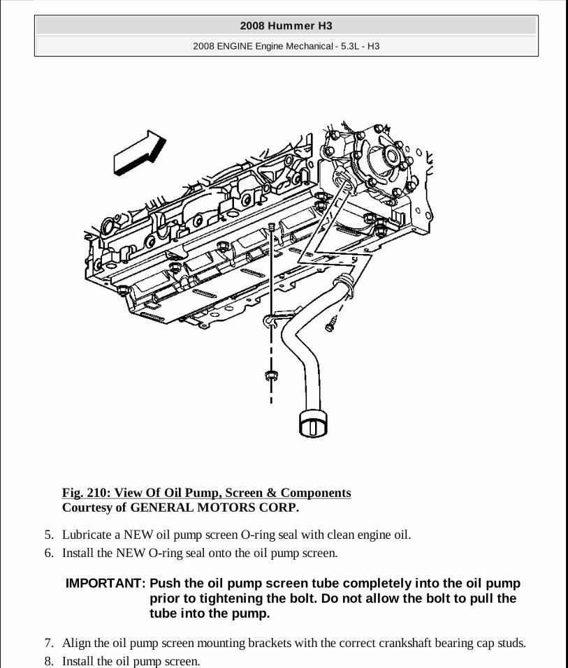
Fig. 210: View Of Oil Pump, Screen & Components Courtesy of GENERAL MOTORS CORP.
5. Lubricate a NEW oil pump screen O-ring seal with clean engine oil. 6. Install the NEW O-ring seal onto the oil pump screen.
7. Align the oil pump screen mounting brackets with the correct crankshaft bearing cap studs. 8. Install the oil pump screen.
IMPORTANT: Push the oil pump screen tube completely into the oil pump prior to tightening the bolt. Do not allow the bolt to pull the tube into the pump.
2008 Hummer H3
2008 ENGINE Engine Mechanical - 5.3L - H3
MY
Sunday, March 29, 2009 10:47:48 PM Page 280 © 2005 Mitchell Repair Information Company, LLC.
9. Install the oil pump screen bolt and nuts.
Tighten: � Tighten the bolt to 12 N.m (106 lb in). � Tighten the nuts to 25 N.m (18 lb ft).
10. Install the engine front cover. Refer to Engine Front Cover Replacement. 11. Install the oil pan. Refer to Oil Pan Replacement.
TIMING CHAIN AND SPROCKET REPLACEMENT
Tools Required
� J 8433-1 Puller Bar
� J 41478 Crankshaft Front Oil Seal Installer. See Special Tools. � J 41558 Crankshaft Sprocket Remover. See Special Tools. � J 41665 Crankshaft Balancer and Sprocket Installer. See Special Tools. � J 41816-2 Crankshaft End Protector
Removal Procedure
2008 Hummer H3
2008 ENGINE Engine Mechanical - 5.3L - H3
MY
Sunday, March 29, 2009 10:47:48 PM Page 281 © 2005 Mitchell Repair Information Company, LLC.
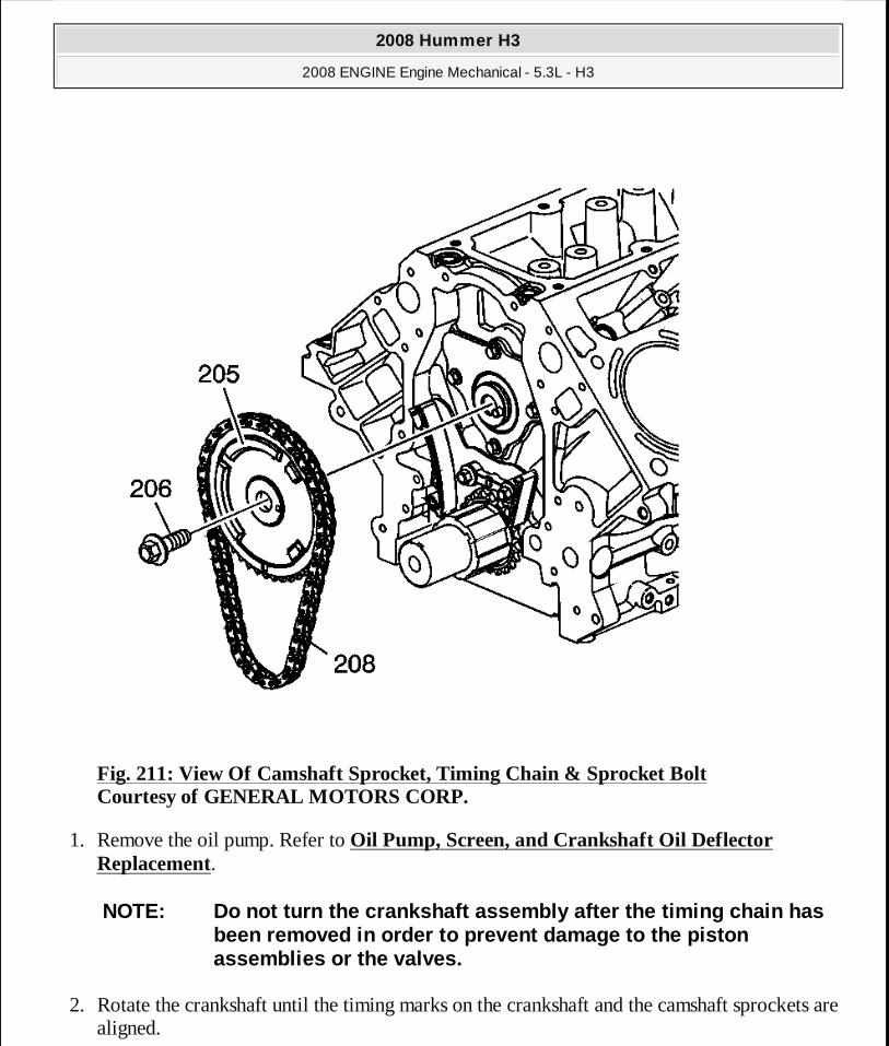
Fig. 211: View Of Camshaft Sprocket, Timing Chain & Sprocket Bolt Courtesy of GENERAL MOTORS CORP.
1. Remove the oil pump. Refer to Oil Pump, Screen, and Crankshaft Oil Deflector Replacement.
2. Rotate the crankshaft until the timing marks on the crankshaft and the camshaft sprockets are aligned.
NOTE: Do not turn the crankshaft assembly after the timing chain has been removed in order to prevent damage to the pist on assemblies or the valves.
2008 Hummer H3
2008 ENGINE Engine Mechanical - 5.3L - H3
MY
Sunday, March 29, 2009 10:47:48 PM Page 282 © 2005 Mitchell Repair Information Company, LLC.

3. Remove and discard the camshaft sprocket bolt (206). 4. Remove the camshaft sprocket (205) and timing chain (208).
Fig. 212: View Of Timing Chain Tensioner & Bolts Courtesy of GENERAL MOTORS CORP.
5. Remove the bolts (231) and timing chain tensioner (232).
NOTE: Do not turn the crankshaft assembly after the timing chain has been removed in order to prevent damage to the pist on assemblies or the valves.
2008 Hummer H3
2008 ENGINE Engine Mechanical - 5.3L - H3
MY
Sunday, March 29, 2009 10:47:48 PM Page 283 © 2005 Mitchell Repair Information Company, LLC.
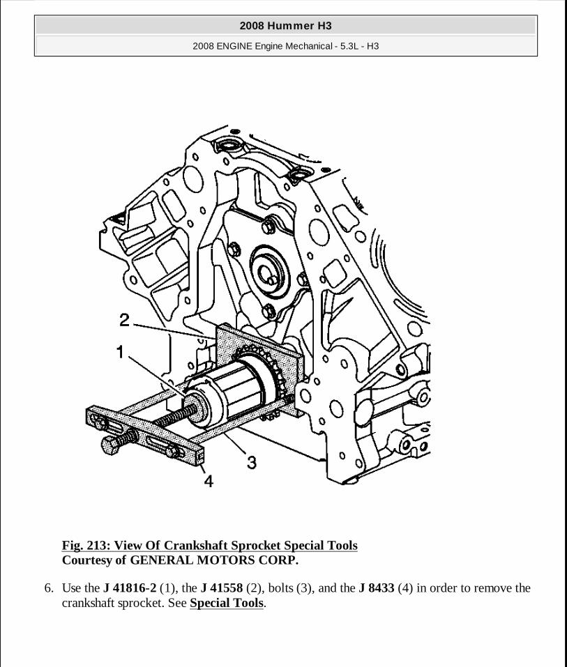
Fig. 213: View Of Crankshaft Sprocket Special Tools Courtesy of GENERAL MOTORS CORP.
6. Use the J 41816-2 (1), the J 41558 (2), bolts (3), and the J 8433 (4) in order to remove the crankshaft sprocket. See Special Tools.
2008 Hummer H3
2008 ENGINE Engine Mechanical - 5.3L - H3
MY
Sunday, March 29, 2009 10:47:48 PM Page 284 © 2005 Mitchell Repair Information Company, LLC.

Fig. 214: View Of Crankshaft Sprocket Courtesy of GENERAL MOTORS CORP.
7. Remove the crankshaft sprocket (207).
2008 Hummer H3
2008 ENGINE Engine Mechanical - 5.3L - H3
MY
Sunday, March 29, 2009 10:47:48 PM Page 285 © 2005 Mitchell Repair Information Company, LLC.

Fig. 215: View Of Crankshaft Key & Keyway Courtesy of GENERAL MOTORS CORP.
8. Remove the crankshaft sprocket key, as required.
Installation Procedure
2008 Hummer H3
2008 ENGINE Engine Mechanical - 5.3L - H3
MY
Sunday, March 29, 2009 10:47:48 PM Page 286 © 2005 Mitchell Repair Information Company, LLC.
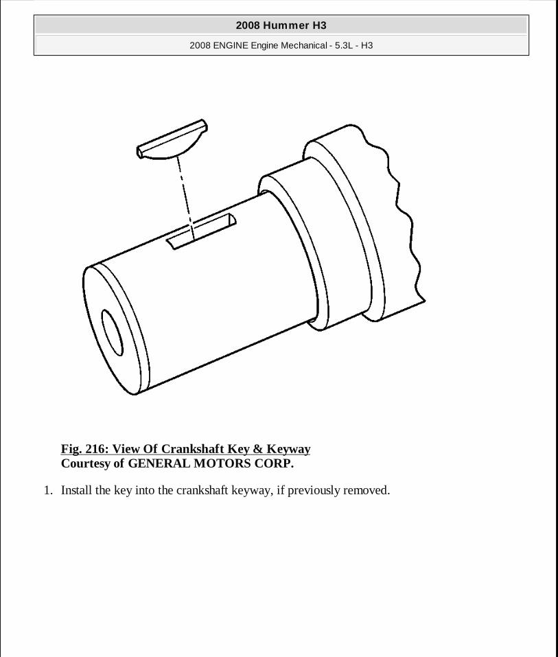
Fig. 216: View Of Crankshaft Key & Keyway Courtesy of GENERAL MOTORS CORP.
1. Install the key into the crankshaft keyway, if previously removed.
2008 Hummer H3
2008 ENGINE Engine Mechanical - 5.3L - H3
MY
Sunday, March 29, 2009 10:47:48 PM Page 287 © 2005 Mitchell Repair Information Company, LLC.
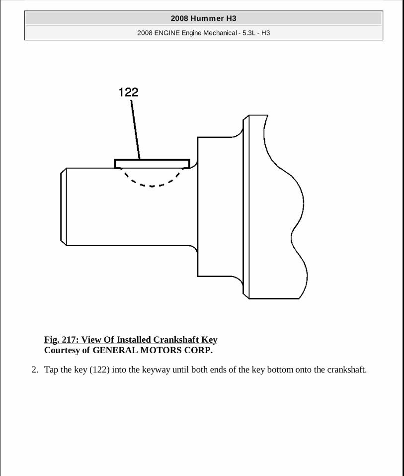
Fig. 217: View Of Installed Crankshaft Key Courtesy of GENERAL MOTORS CORP.
2. Tap the key (122) into the keyway until both ends of the key bottom onto the crankshaft.
2008 Hummer H3
2008 ENGINE Engine Mechanical - 5.3L - H3
MY
Sunday, March 29, 2009 10:47:48 PM Page 288 © 2005 Mitchell Repair Information Company, LLC.
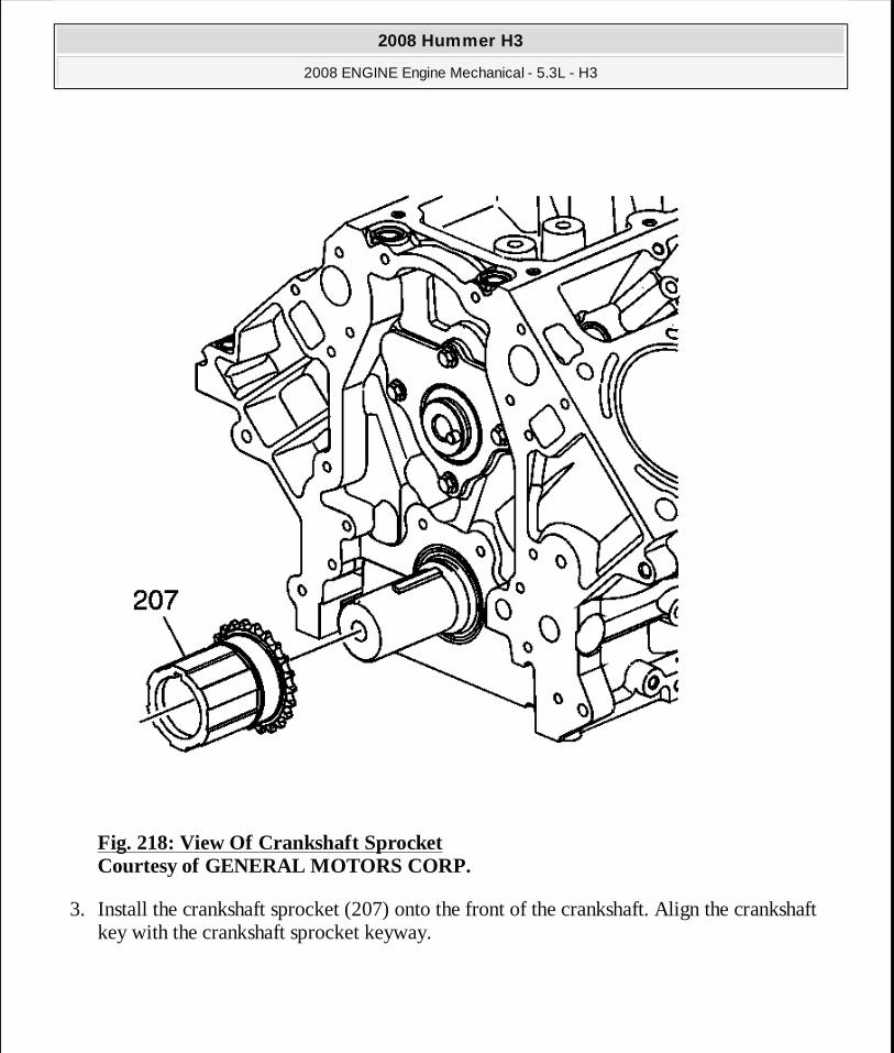
Fig. 218: View Of Crankshaft Sprocket Courtesy of GENERAL MOTORS CORP.
3. Install the crankshaft sprocket (207) onto the front of the crankshaft. Align the crankshaft key with the crankshaft sprocket keyway.
2008 Hummer H3
2008 ENGINE Engine Mechanical - 5.3L - H3
MY
Sunday, March 29, 2009 10:47:48 PM Page 289 © 2005 Mitchell Repair Information Company, LLC.
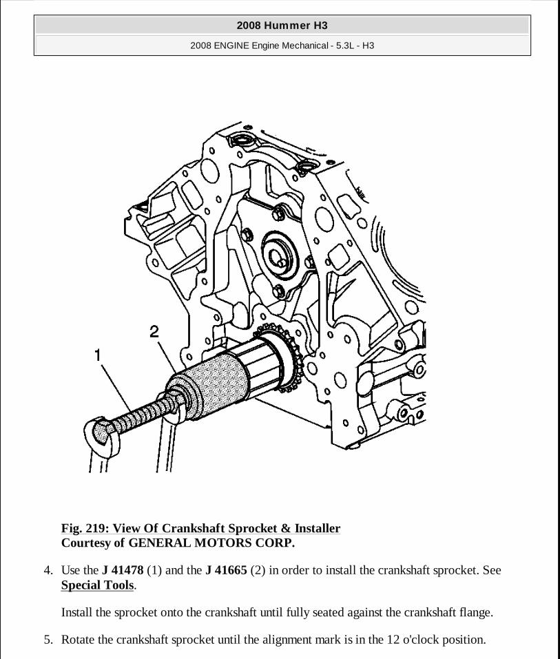
Fig. 219: View Of Crankshaft Sprocket & Installer Courtesy of GENERAL MOTORS CORP.
4. Use the J 41478 (1) and the J 41665 (2) in order to install the crankshaft sprocket. See Special Tools.
Install the sprocket onto the crankshaft until fully seated against the crankshaft flange.
5. Rotate the crankshaft sprocket until the alignment mark is in the 12 o'clock position.
2008 Hummer H3
2008 ENGINE Engine Mechanical - 5.3L - H3
MY
Sunday, March 29, 2009 10:47:48 PM Page 290 © 2005 Mitchell Repair Information Company, LLC.
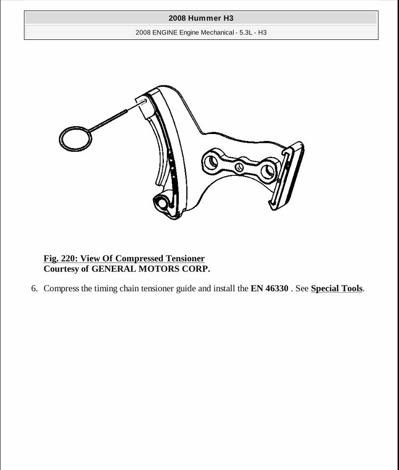
Fig. 220: View Of Compressed Tensioner Courtesy of GENERAL MOTORS CORP.
6. Compress the timing chain tensioner guide and install the EN 46330 . See Special Tools.
2008 Hummer H3
2008 ENGINE Engine Mechanical - 5.3L - H3
MY
Sunday, March 29, 2009 10:47:48 PM Page 291 © 2005 Mitchell Repair Information Company, LLC.
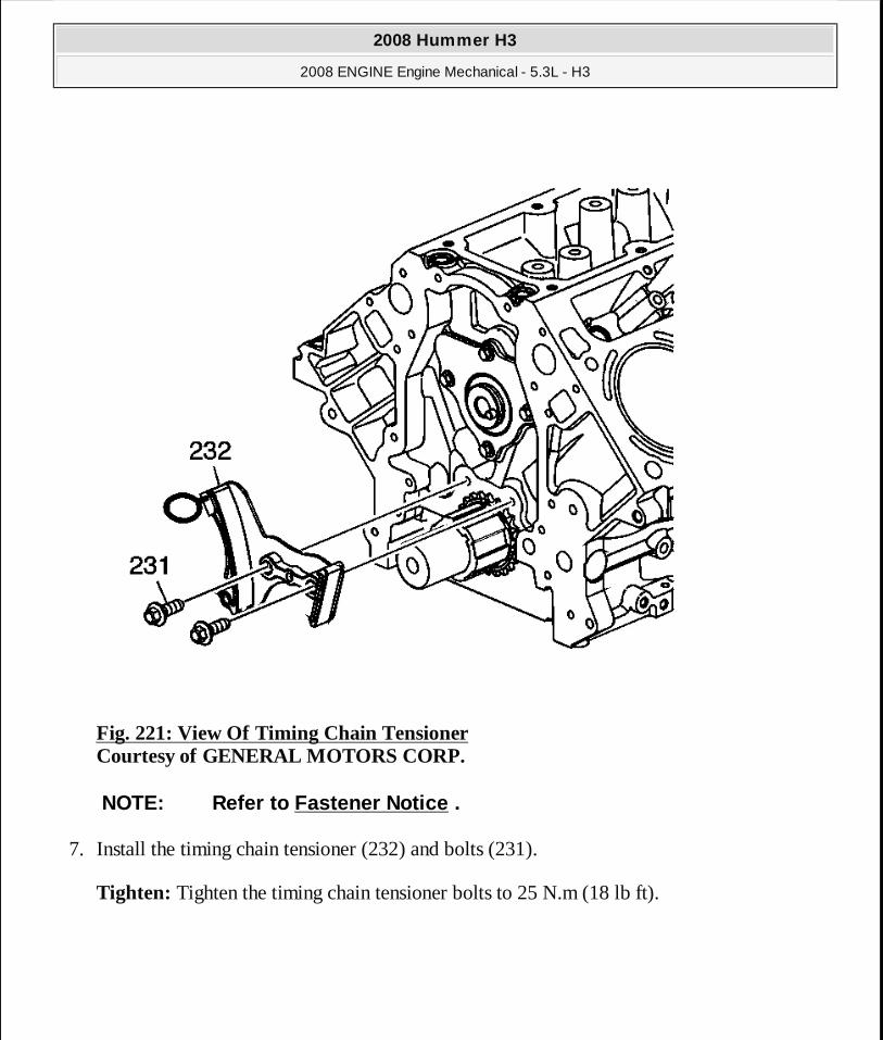
Fig. 221: View Of Timing Chain Tensioner Courtesy of GENERAL MOTORS CORP.
7. Install the timing chain tensioner (232) and bolts (231).
Tighten: Tighten the timing chain tensioner bolts to 25 N.m (18 lb ft).
NOTE: Refer to Fastener Notice .
2008 Hummer H3
2008 ENGINE Engine Mechanical - 5.3L - H3
MY
Sunday, March 29, 2009 10:47:48 PM Page 292 © 2005 Mitchell Repair Information Company, LLC.

Fig. 222: View Of Camshaft Sprocket & Timing Chain Courtesy of GENERAL MOTORS CORP.
8. Install the camshaft sprocket (205), timing chain (208), and bolt (206).
IMPORTANT:� The sprocket teeth and timing chain must mesh. � The camshaft and the crankshaft sprocket alignment
marks MUST be aligned properly.
2008 Hummer H3
2008 ENGINE Engine Mechanical - 5.3L - H3
MY
Sunday, March 29, 2009 10:47:48 PM Page 293 © 2005 Mitchell Repair Information Company, LLC.
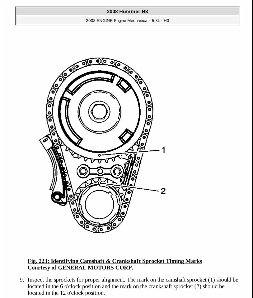
Fig. 223: Identifying Camshaft & Crankshaft Sprocket Timing Marks Courtesy of GENERAL MOTORS CORP.
9. Inspect the sprockets for proper alignment. The mark on the camshaft sprocket (1) should be located in the 6 o'clock position and the mark on the crankshaft sprocket (2) should be located in the 12 o'clock position.
2008 Hummer H3
2008 ENGINE Engine Mechanical - 5.3L - H3
MY
Sunday, March 29, 2009 10:47:48 PM Page 294 © 2005 Mitchell Repair Information Company, LLC.

Fig. 224: Locating Tensioner Pin Courtesy of GENERAL MOTORS CORP.
10. Remove the EN 46330 . See Special Tools.
IMPORTANT: Do not apply threadlock to the flex plate bolts at this time.
2008 Hummer H3
2008 ENGINE Engine Mechanical - 5.3L - H3
MY
Sunday, March 29, 2009 10:47:49 PM Page 295 © 2005 Mitchell Repair Information Company, LLC.

11. Temporarily install the automatic transmission flex plate and bolts. Refer to Automatic Transmission Flex Plate Cleaning and Inspection.
Fig. 225: Identifying J 42386-A Flywheel Holding Tool Courtesy of GENERAL MOTORS CORP.
12. Install the J 42386-A and bolts. See Special Tools. Use 1 M10-1.5 x 120 mm bolt and 1 M10-1.5 x 45 mm bolt for proper tool operation.
Tighten: Tighten the J 42386-A bolts to 50 N. See Special Tools.m (37 lb ft).
2008 Hummer H3
2008 ENGINE Engine Mechanical - 5.3L - H3
MY
Sunday, March 29, 2009 10:47:49 PM Page 296 © 2005 Mitchell Repair Information Company, LLC.
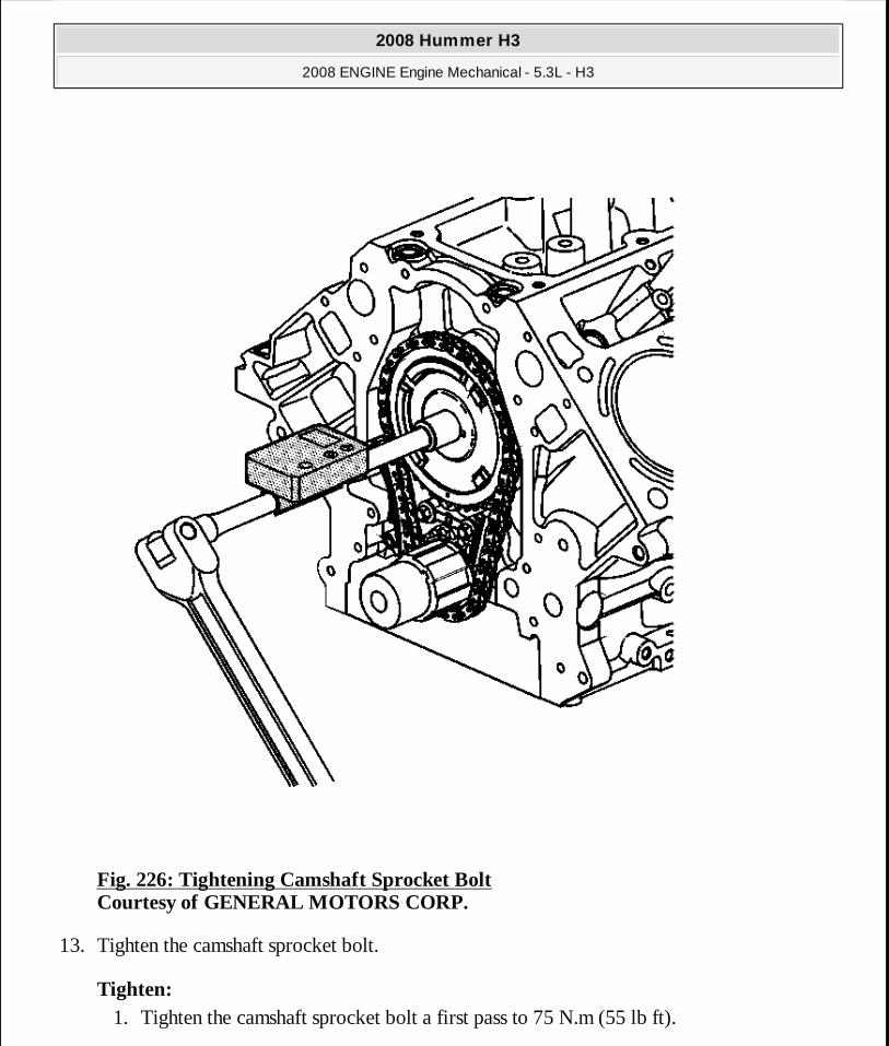
Fig. 226: Tightening Camshaft Sprocket Bolt Courtesy of GENERAL MOTORS CORP.
13. Tighten the camshaft sprocket bolt.
Tighten: 1. Tighten the camshaft sprocket bolt a first pass to 75 N.m (55 lb ft).
2008 Hummer H3
2008 ENGINE Engine Mechanical - 5.3L - H3
MY
Sunday, March 29, 2009 10:47:49 PM Page 297 © 2005 Mitchell Repair Information Company, LLC.
2. Tighten the camshaft sprocket bolt a final pass an additional 50 degrees using the J 45059 .
14. Remove the J 42386-A and bolts. See Special Tools. 15. Remove the automatic transmission flex plate and bolts. Refer to Automatic Transmission
Flex Plate Removal. 16. Install the oil pump. Refer to Oil Pump, Screen, and Crankshaft Oil Deflector
Replacement.
CAMSHAFT REPLACEMENT
Special Tools
� EN 46330 Timing Belt Tensioner Retaining Pin. See Special Tools. � EN 46330 Angle Meter. See Special Tools.
Removal Procedure
1. Remove the condenser. Refer to Condenser Replacement . 2. Remove the engine front cover. Refer to Engine Front Cover Replacement. 3. Remove all of the valve lifters. Refer to Valve Lifter Replacement.
2008 Hummer H3
2008 ENGINE Engine Mechanical - 5.3L - H3
MY
Sunday, March 29, 2009 10:47:49 PM Page 298 © 2005 Mitchell Repair Information Company, LLC.
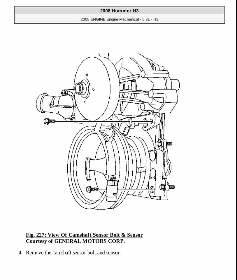
Fig. 227: View Of Camshaft Sensor Bolt & Sensor Courtesy of GENERAL MOTORS CORP.
4. Remove the camshaft sensor bolt and sensor.
2008 Hummer H3
2008 ENGINE Engine Mechanical - 5.3L - H3
MY
Sunday, March 29, 2009 10:47:49 PM Page 299 © 2005 Mitchell Repair Information Company, LLC.

Fig. 228: Identifying Camshaft & Crankshaft Sprocket Timing Marks Courtesy of GENERAL MOTORS CORP.
5. Rotate the crankshaft until the timing marks on the crankshaft and camshaft sprockets are aligned.
2008 Hummer H3
2008 ENGINE Engine Mechanical - 5.3L - H3
MY
Sunday, March 29, 2009 10:47:49 PM Page 300 © 2005 Mitchell Repair Information Company, LLC.

Fig. 229: Camshaft Sprocket Bolt Courtesy of GENERAL MOTORS CORP.
6. Remove the camshaft sprocket bolt (206).
2008 Hummer H3
2008 ENGINE Engine Mechanical - 5.3L - H3
MY
Sunday, March 29, 2009 10:47:49 PM Page 301 © 2005 Mitchell Repair Information Company, LLC.
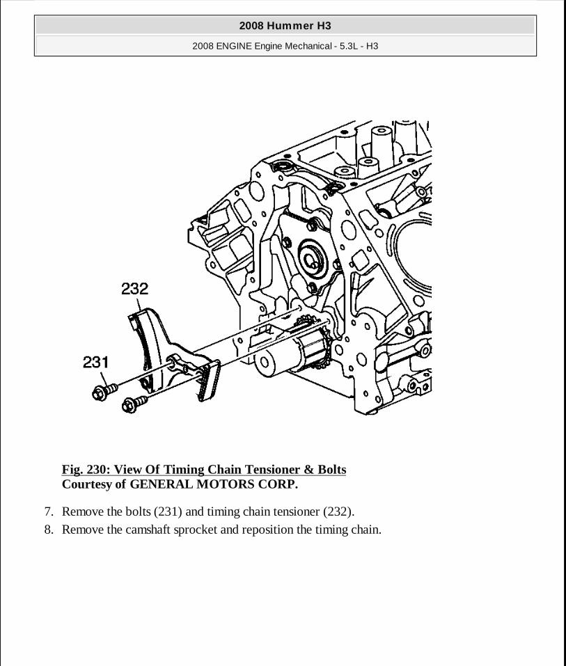
Fig. 230: View Of Timing Chain Tensioner & Bolts Courtesy of GENERAL MOTORS CORP.
7. Remove the bolts (231) and timing chain tensioner (232). 8. Remove the camshaft sprocket and reposition the timing chain.
2008 Hummer H3
2008 ENGINE Engine Mechanical - 5.3L - H3
MY
Sunday, March 29, 2009 10:47:49 PM Page 302 © 2005 Mitchell Repair Information Company, LLC.
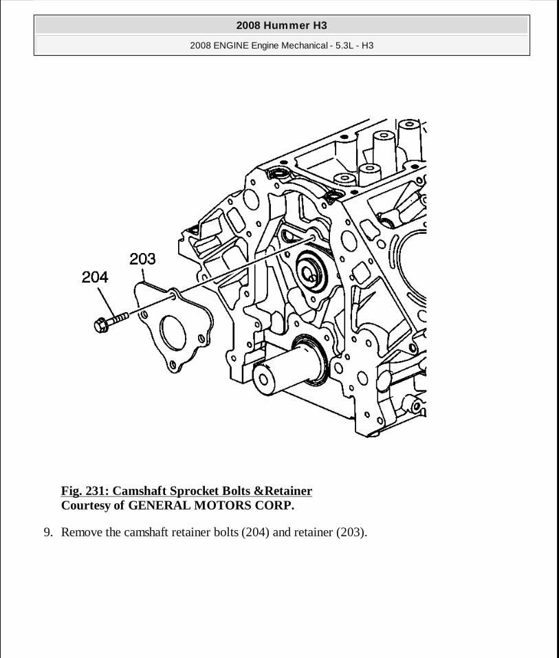
Fig. 231: Camshaft Sprocket Bolts &Retainer Courtesy of GENERAL MOTORS CORP.
9. Remove the camshaft retainer bolts (204) and retainer (203).
2008 Hummer H3
2008 ENGINE Engine Mechanical - 5.3L - H3
MY
Sunday, March 29, 2009 10:47:49 PM Page 303 © 2005 Mitchell Repair Information Company, LLC.
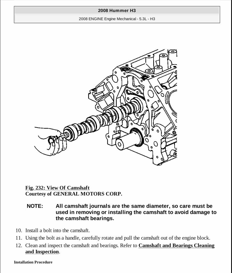
Fig. 232: View Of Camshaft Courtesy of GENERAL MOTORS CORP.
10. Install a bolt into the camshaft. 11. Using the bolt as a handle, carefully rotate and pull the camshaft out of the engine block.
12. Clean and inspect the camshaft and bearings. Refer to Camshaft and Bearings Cleaning and Inspection.
Installation Procedure
NOTE: All camshaft journals are the same diameter, s o care must be used in removing or installing the camshaft to avoi d damage to the camshaft bearings.
2008 Hummer H3
2008 ENGINE Engine Mechanical - 5.3L - H3
MY
Sunday, March 29, 2009 10:47:49 PM Page 304 © 2005 Mitchell Repair Information Company, LLC.

Fig. 233: View Of Camshaft Courtesy of GENERAL MOTORS CORP.
1. Lubricate the camshaft journals and the bearings with clean engine oil.
2. Using the bolt as a handle, carefully install the camshaft into the engine block. 3. Remove the bolt from the front of the camshaft.
IMPORTANT: If camshaft replacement is required, the valve lifters must also be replaced.
NOTE: All camshaft journals are the same diameter, s o care must be used in removing or installing the camshaft to avoi d damage to the camshaft bearings.
2008 Hummer H3
2008 ENGINE Engine Mechanical - 5.3L - H3
MY
Sunday, March 29, 2009 10:47:49 PM Page 305 © 2005 Mitchell Repair Information Company, LLC.
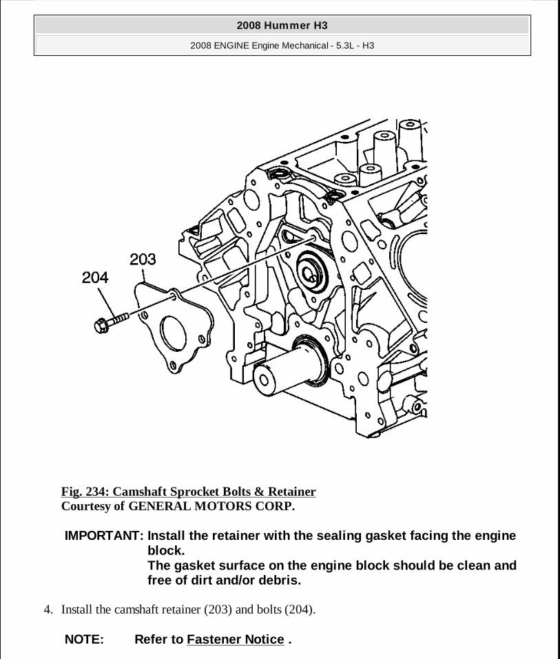
Fig. 234: Camshaft Sprocket Bolts & Retainer Courtesy of GENERAL MOTORS CORP.
4. Install the camshaft retainer (203) and bolts (204).
IMPORTANT: Install the retainer with the sealing gas ket facing the engine block. The gasket surface on the engine block should be cl ean and free of dirt and/or debris.
NOTE: Refer to Fastener Notice .
2008 Hummer H3
2008 ENGINE Engine Mechanical - 5.3L - H3
MY
Sunday, March 29, 2009 10:47:49 PM Page 306 © 2005 Mitchell Repair Information Company, LLC.

5. Tighten the camshaft retainer bolts.
Tighten: � Tighten the first design hex head bolts (3) to 25 N.m (18 lb ft). � Tighten the second design TORX® head bolts (4) to 15 N.m (11 lb ft).
6. Compress the timing chain tensioner guide and install the EN 46330 . See Special Tools.
Fig. 235: View Of Timing Chain Tensioner Courtesy of GENERAL MOTORS CORP.
7. Install the timing chain tensioner (232) and bolts (231).
2008 Hummer H3
2008 ENGINE Engine Mechanical - 5.3L - H3
MY
Sunday, March 29, 2009 10:47:49 PM Page 307 © 2005 Mitchell Repair Information Company, LLC.

Tighten: Tighten the timing chain tensioner bolts to 25 N.m (18 lb ft).
Fig. 236: Identifying Camshaft & Crankshaft Sprocket Timing Marks Courtesy of GENERAL MOTORS CORP.
IMPORTANT:� Properly locate the camshaft sprocket locating pin with
2008 Hummer H3
2008 ENGINE Engine Mechanical - 5.3L - H3
MY
Sunday, March 29, 2009 10:47:49 PM Page 308 © 2005 Mitchell Repair Information Company, LLC.
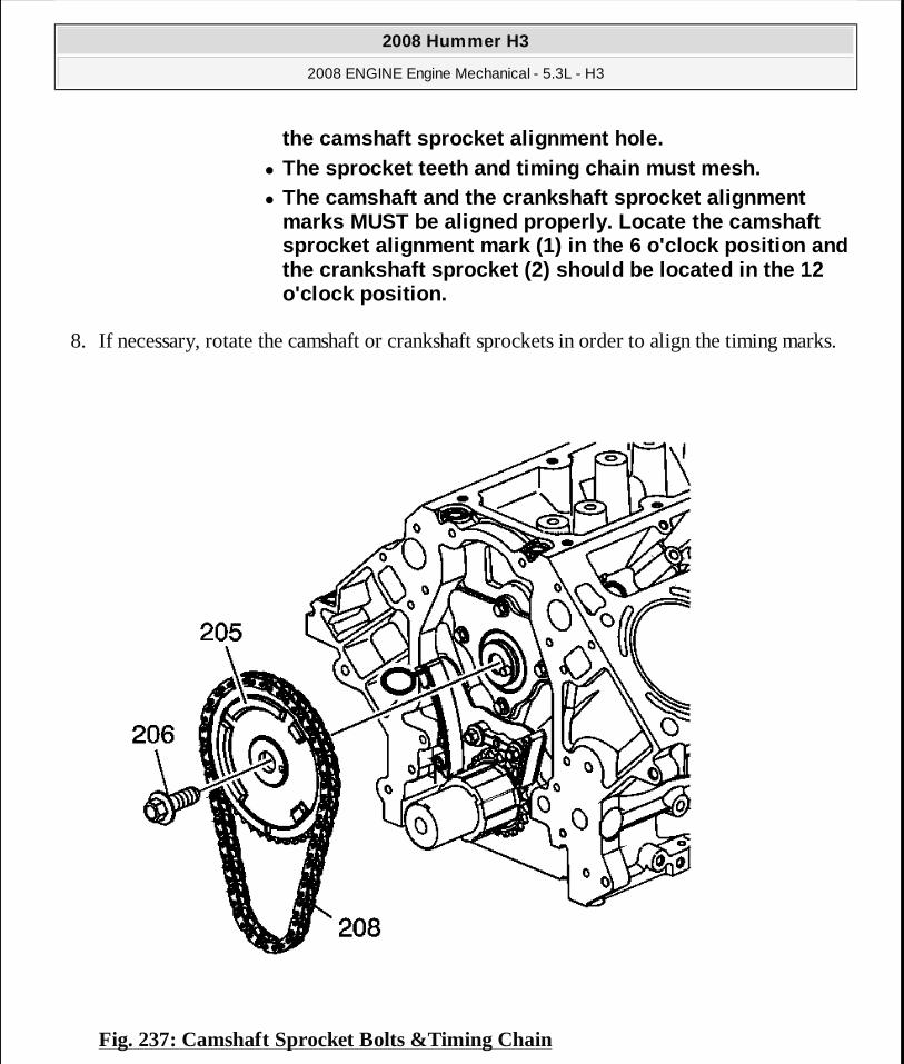
8. If necessary, rotate the camshaft or crankshaft sprockets in order to align the timing marks.
Fig. 237: Camshaft Sprocket Bolts &Timing Chain
the camshaft sprocket alignment hole. � The sprocket teeth and timing chain must mesh. � The camshaft and the crankshaft sprocket alignment
marks MUST be aligned properly. Locate the camshaft sprocket alignment mark (1) in the 6 o'clock positi on and the crankshaft sprocket (2) should be located in th e 12 o'clock position.
2008 Hummer H3
2008 ENGINE Engine Mechanical - 5.3L - H3
MY
Sunday, March 29, 2009 10:47:49 PM Page 309 © 2005 Mitchell Repair Information Company, LLC.
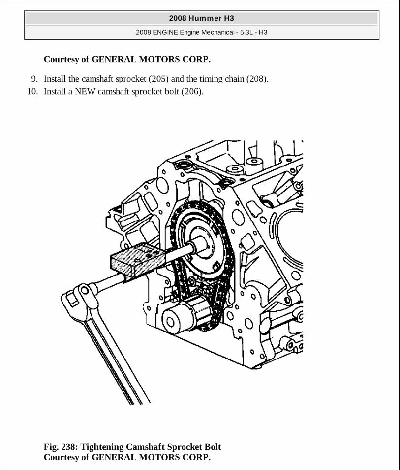
Courtesy of GENERAL MOTORS CORP.
9. Install the camshaft sprocket (205) and the timing chain (208). 10. Install a NEW camshaft sprocket bolt (206).
Fig. 238: Tightening Camshaft Sprocket Bolt Courtesy of GENERAL MOTORS CORP.
2008 Hummer H3
2008 ENGINE Engine Mechanical - 5.3L - H3
MY
Sunday, March 29, 2009 10:47:49 PM Page 310 © 2005 Mitchell Repair Information Company, LLC.
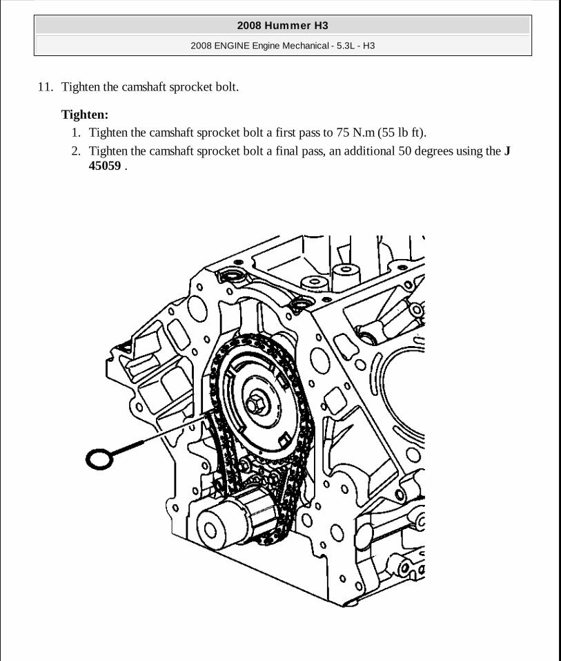
11. Tighten the camshaft sprocket bolt.
Tighten: 1. Tighten the camshaft sprocket bolt a first pass to 75 N.m (55 lb ft).
2. Tighten the camshaft sprocket bolt a final pass, an additional 50 degrees using the J 45059 .
2008 Hummer H3
2008 ENGINE Engine Mechanical - 5.3L - H3
MY
Sunday, March 29, 2009 10:47:49 PM Page 311 © 2005 Mitchell Repair Information Company, LLC.
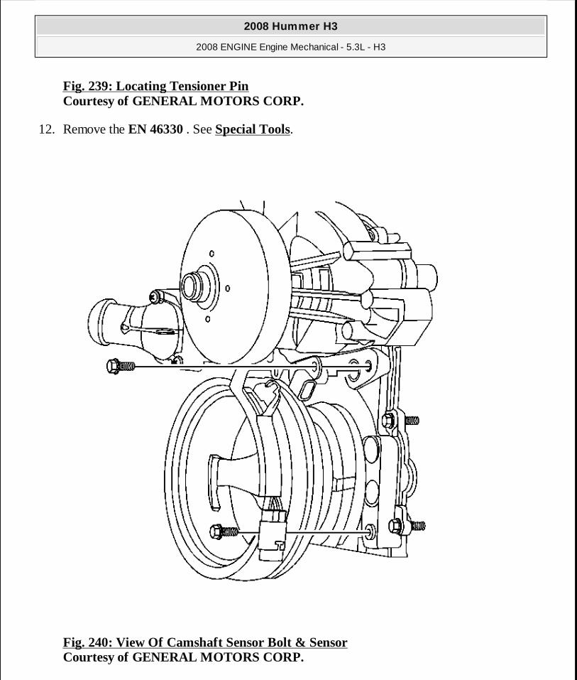
Fig. 239: Locating Tensioner Pin Courtesy of GENERAL MOTORS CORP.
12. Remove the EN 46330 . See Special Tools.
Fig. 240: View Of Camshaft Sensor Bolt & Sensor Courtesy of GENERAL MOTORS CORP.
2008 Hummer H3
2008 ENGINE Engine Mechanical - 5.3L - H3
MY
Sunday, March 29, 2009 10:47:49 PM Page 312 © 2005 Mitchell Repair Information Company, LLC.
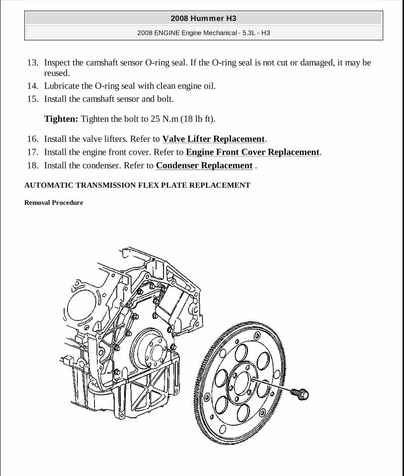
13. Inspect the camshaft sensor O-ring seal. If the O-ring seal is not cut or damaged, it may be reused.
14. Lubricate the O-ring seal with clean engine oil. 15. Install the camshaft sensor and bolt.
Tighten: Tighten the bolt to 25 N.m (18 lb ft).
16. Install the valve lifters. Refer to Valve Lifter Replacement. 17. Install the engine front cover. Refer to Engine Front Cover Replacement. 18. Install the condenser. Refer to Condenser Replacement .
AUTOMATIC TRANSMISSION FLEX PLATE REPLACEMENT
Removal Procedure
2008 Hummer H3
2008 ENGINE Engine Mechanical - 5.3L - H3
MY
Sunday, March 29, 2009 10:47:49 PM Page 313 © 2005 Mitchell Repair Information Company, LLC.
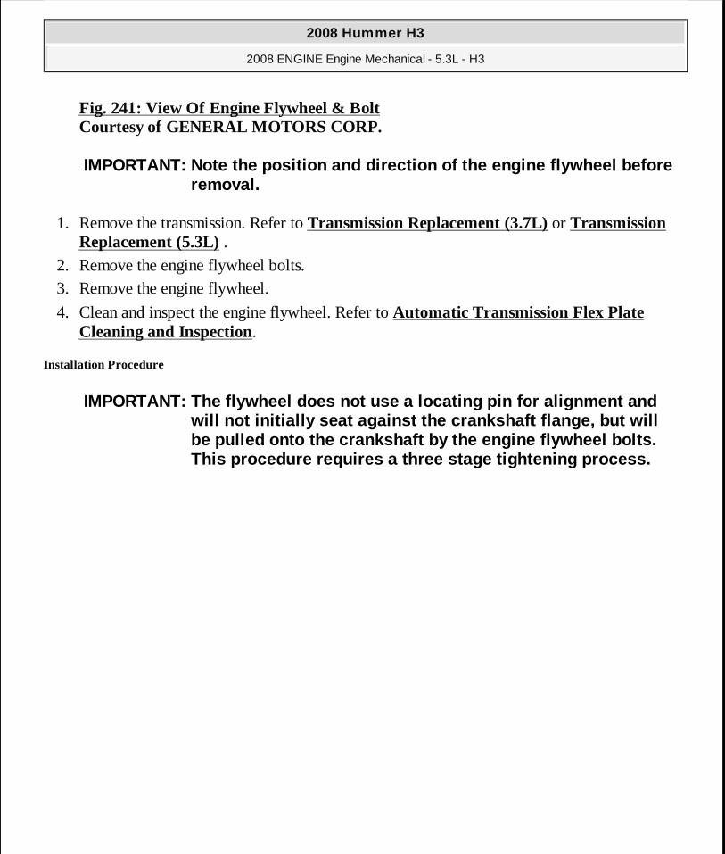
Fig. 241: View Of Engine Flywheel & Bolt Courtesy of GENERAL MOTORS CORP.
1. Remove the transmission. Refer to Transmission Replacement (3.7L) or Transmission Replacement (5.3L) .
2. Remove the engine flywheel bolts. 3. Remove the engine flywheel.
4. Clean and inspect the engine flywheel. Refer to Automatic Transmission Flex Plate Cleaning and Inspection.
Installation Procedure
IMPORTANT: Note the position and direction of the en gine flywheel before removal.
IMPORTANT: The flywheel does not use a locating pin for alignment and will not initially seat against the crankshaft flan ge, but will be pulled onto the crankshaft by the engine flywhee l bolts. This procedure requires a three stage tightening pr ocess.
2008 Hummer H3
2008 ENGINE Engine Mechanical - 5.3L - H3
MY
Sunday, March 29, 2009 10:47:49 PM Page 314 © 2005 Mitchell Repair Information Company, LLC.
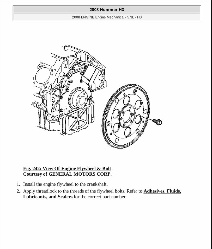
Fig. 242: View Of Engine Flywheel & Bolt Courtesy of GENERAL MOTORS CORP.
1. Install the engine flywheel to the crankshaft.
2. Apply threadlock to the threads of the flywheel bolts. Refer to Adhesives, Fluids, Lubricants, and Sealers for the correct part number.
2008 Hummer H3
2008 ENGINE Engine Mechanical - 5.3L - H3
MY
Sunday, March 29, 2009 10:47:49 PM Page 315 © 2005 Mitchell Repair Information Company, LLC.
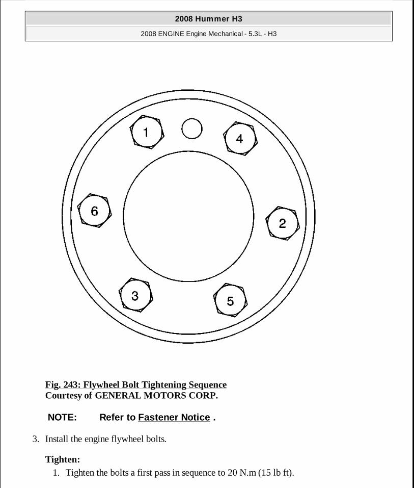
Fig. 243: Flywheel Bolt Tightening Sequence Courtesy of GENERAL MOTORS CORP.
3. Install the engine flywheel bolts.
Tighten: 1. Tighten the bolts a first pass in sequence to 20 N.m (15 lb ft).
NOTE: Refer to Fastener Notice .
2008 Hummer H3
2008 ENGINE Engine Mechanical - 5.3L - H3
MY
Sunday, March 29, 2009 10:47:49 PM Page 316 © 2005 Mitchell Repair Information Company, LLC.
2. Tighten the bolts a second pass in sequence to 50 N.m (37 lb ft). 3. Tighten the bolts a final pass in sequence to 100 N.m (74 lb ft).
4. Install the transmission. Refer to Transmission Replacement (3.7L) or Transmission Replacement (5.3L) .
ENGINE REPLACEMENT
Special Tools
� J 21366 Converter Holding Strap. See Special Tools. � J 38185 Hose Clamp Pliers
� J 41798 Engine Lift Bracket. See Special Tools.
Removal Procedure
1. Remove the hood. Refer to Hood Replacement . 2. Place fender covers over both fenders.
3. Disconnect the negative battery cable. Refer to Battery Negative Cable Disconnection and Connection .
4. Recover the refrigerant. Refer to Refrigerant Recovery and Recharging (Non HP2) . 5. Remove the radiator. Refer to Radiator Replacement . 6. Remove the intake manifold. Refer to Intake Manifold Replacement. 7. Disconnect the oil pressure sensor and the oxygen sensors from the rear of the engine.
2008 Hummer H3
2008 ENGINE Engine Mechanical - 5.3L - H3
MY
Sunday, March 29, 2009 10:47:50 PM Page 317 © 2005 Mitchell Repair Information Company, LLC.
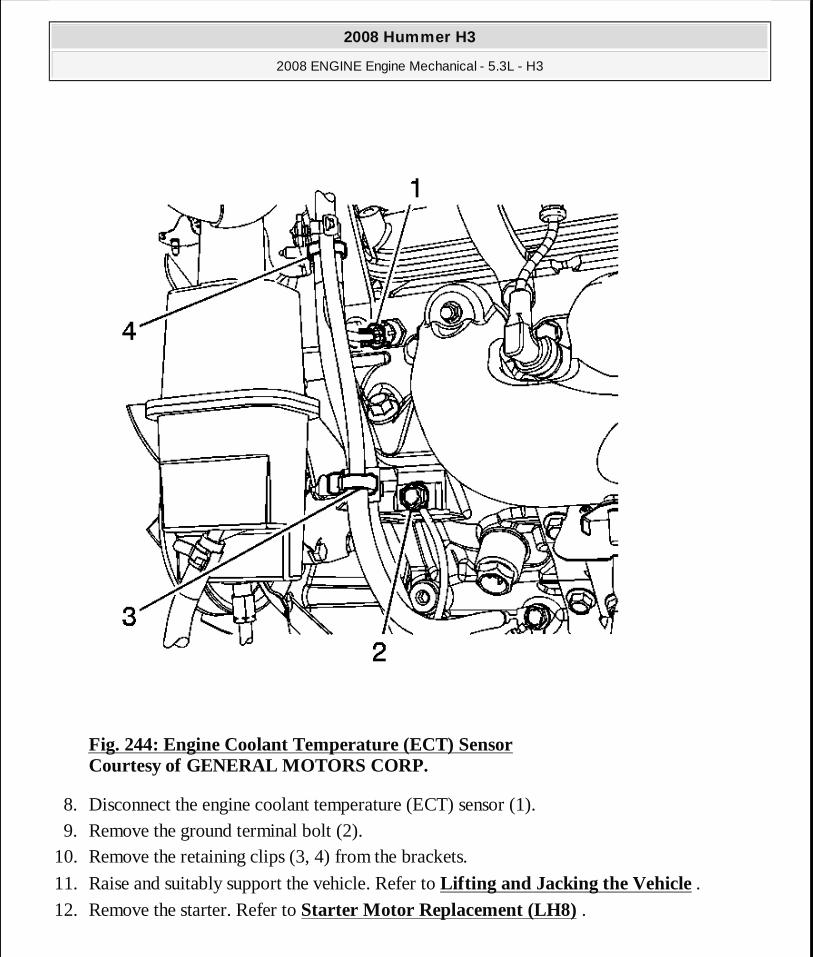
Fig. 244: Engine Coolant Temperature (ECT) Sensor Courtesy of GENERAL MOTORS CORP.
8. Disconnect the engine coolant temperature (ECT) sensor (1). 9. Remove the ground terminal bolt (2).
10. Remove the retaining clips (3, 4) from the brackets.
11. Raise and suitably support the vehicle. Refer to Lifting and Jacking the Vehicle .
12. Remove the starter. Refer to Starter Motor Replacement (LH8) .
2008 Hummer H3
2008 ENGINE Engine Mechanical - 5.3L - H3
MY
Sunday, March 29, 2009 10:47:50 PM Page 318 © 2005 Mitchell Repair Information Company, LLC.
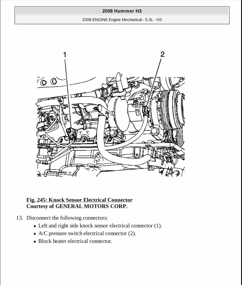
Fig. 245: Knock Sensor Electrical Connector Courtesy of GENERAL MOTORS CORP.
13. Disconnect the following connectors: � Left and right side knock sensor electrical connector (1). � A/C pressure switch electrical connector (2). � Block heater electrical connector.
2008 Hummer H3
2008 ENGINE Engine Mechanical - 5.3L - H3
MY
Sunday, March 29, 2009 10:47:50 PM Page 319 © 2005 Mitchell Repair Information Company, LLC.
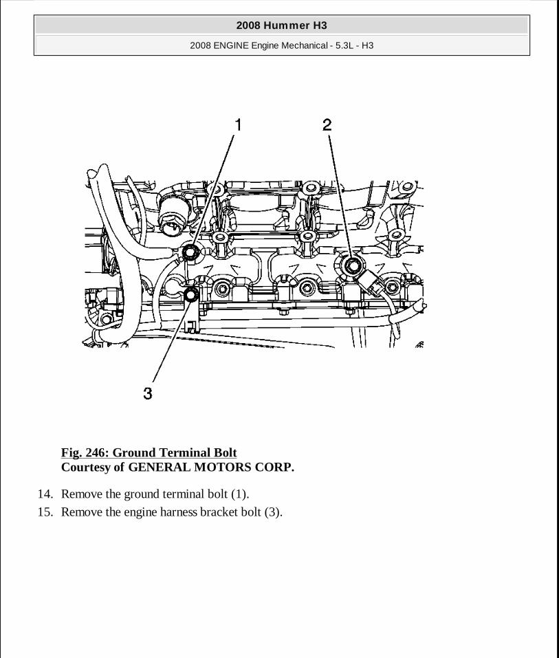
Fig. 246: Ground Terminal Bolt Courtesy of GENERAL MOTORS CORP.
14. Remove the ground terminal bolt (1). 15. Remove the engine harness bracket bolt (3).
2008 Hummer H3
2008 ENGINE Engine Mechanical - 5.3L - H3
MY
Sunday, March 29, 2009 10:47:50 PM Page 320 © 2005 Mitchell Repair Information Company, LLC.
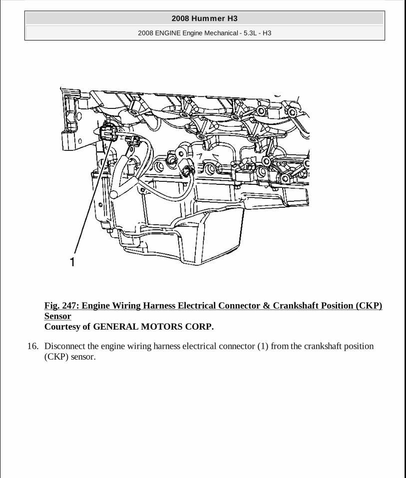
Fig. 247: Engine Wiring Harness Electrical Connector & Crankshaft Position (CKP) Sensor Courtesy of GENERAL MOTORS CORP.
16. Disconnect the engine wiring harness electrical connector (1) from the crankshaft position (CKP) sensor.
2008 Hummer H3
2008 ENGINE Engine Mechanical - 5.3L - H3
MY
Sunday, March 29, 2009 10:47:50 PM Page 321 © 2005 Mitchell Repair Information Company, LLC.

Fig. 248: Engine Wiring Harness Electrical Connector & Crankshaft Position (CKP) Sensor Wire Harness Courtesy of GENERAL MOTORS CORP.
17. Disconnect the engine wiring harness electrical connector (9) from the camshaft position (CMP) sensor wire harness.
2008 Hummer H3
2008 ENGINE Engine Mechanical - 5.3L - H3
MY
Sunday, March 29, 2009 10:47:50 PM Page 322 © 2005 Mitchell Repair Information Company, LLC.

Fig. 249: View Of Battery Cable Channel & Bolt Courtesy of GENERAL MOTORS CORP.
18. Remove the battery cable channel bolt. 19. Remove the battery cable channel from the oil pan. 20. Lower the vehicle. 21. Gather all branches of the engine wiring harness and reposition the harness off to the side.
2008 Hummer H3
2008 ENGINE Engine Mechanical - 5.3L - H3
MY
Sunday, March 29, 2009 10:47:50 PM Page 323 © 2005 Mitchell Repair Information Company, LLC.

Fig. 250: Engine Wiring Harness/Positive Battery Cable Boot Courtesy of GENERAL MOTORS CORP.
22. Disconnect the engine wiring harness electrical connector (1) from the generator. 23. Reposition the engine wiring harness/positive battery cable boot (5). 24. Remove the engine wiring harness/positive battery cable nut from the generator. 25. Remove the engine wiring harness/positive battery cable (2) from the generator.
2008 Hummer H3
2008 ENGINE Engine Mechanical - 5.3L - H3
MY
Sunday, March 29, 2009 10:47:50 PM Page 324 © 2005 Mitchell Repair Information Company, LLC.
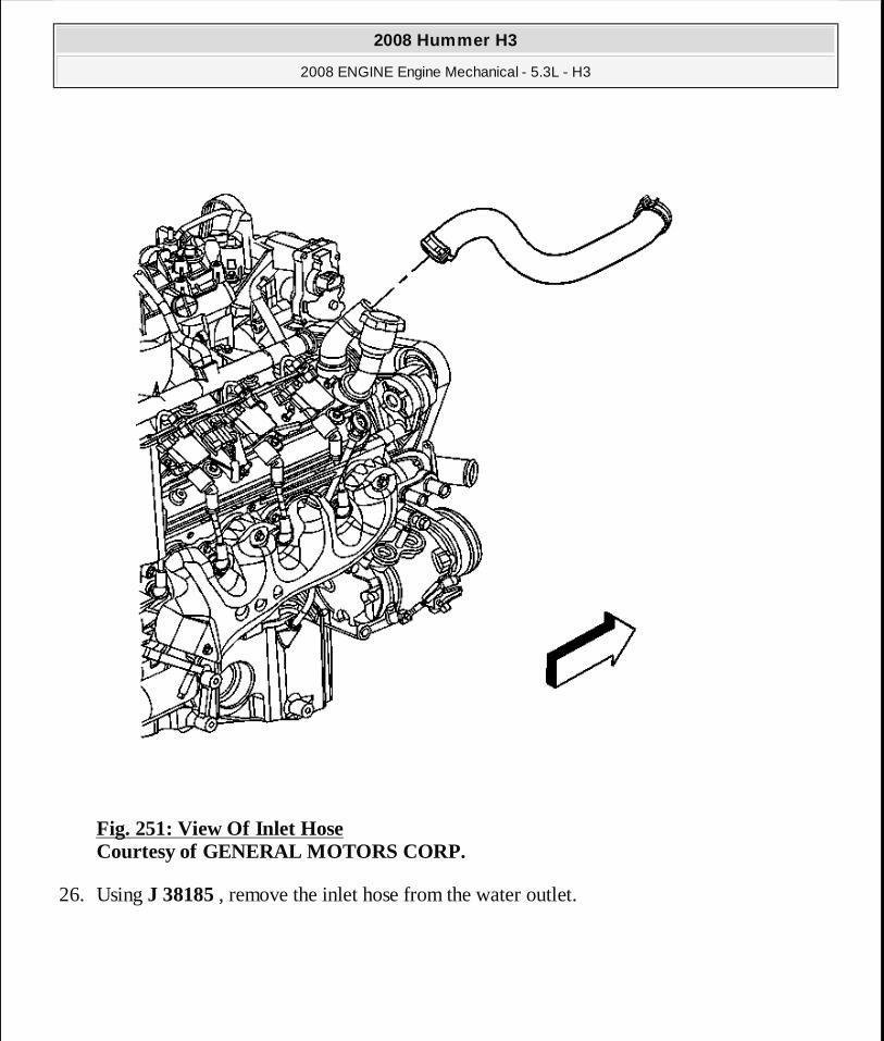
Fig. 251: View Of Inlet Hose Courtesy of GENERAL MOTORS CORP.
26. Using J 38185 , remove the inlet hose from the water outlet.
2008 Hummer H3
2008 ENGINE Engine Mechanical - 5.3L - H3
MY
Sunday, March 29, 2009 10:47:50 PM Page 325 © 2005 Mitchell Repair Information Company, LLC.

Fig. 252: Outlet Hose & Water Outlet Courtesy of GENERAL MOTORS CORP.
27. Using J 38185 , remove the outlet hose (1) from the water outlet.
28. Remove the heater inlet and outlet hoses. Refer to Heater Inlet Hose Replacement (Right Hand Drive) or Heater Outlet Hose Replacement (Right Hand Drive) .
29. Raise the vehicle.
30. Remove the catalytic converters. Refer to Catalytic Converter Replacement - Left Side (LH8) and Catalytic Converter Replacement - Right Side (LH8) .
31. Remove the 3 bracket bolts from both the right and the left side engine mounts. Refer to
2008 Hummer H3
2008 ENGINE Engine Mechanical - 5.3L - H3
MY
Sunday, March 29, 2009 10:47:50 PM Page 326 © 2005 Mitchell Repair Information Company, LLC.

Engine Mount Replacement - Left Side and Engine Mount Replacement - Right Side
Fig. 253: Flywheel-To-Torque Converter Bolts Courtesy of GENERAL MOTORS CORP.
32. Remove the torque converter bolts.
2008 Hummer H3
2008 ENGINE Engine Mechanical - 5.3L - H3
MY
Sunday, March 29, 2009 10:47:50 PM Page 327 © 2005 Mitchell Repair Information Company, LLC.
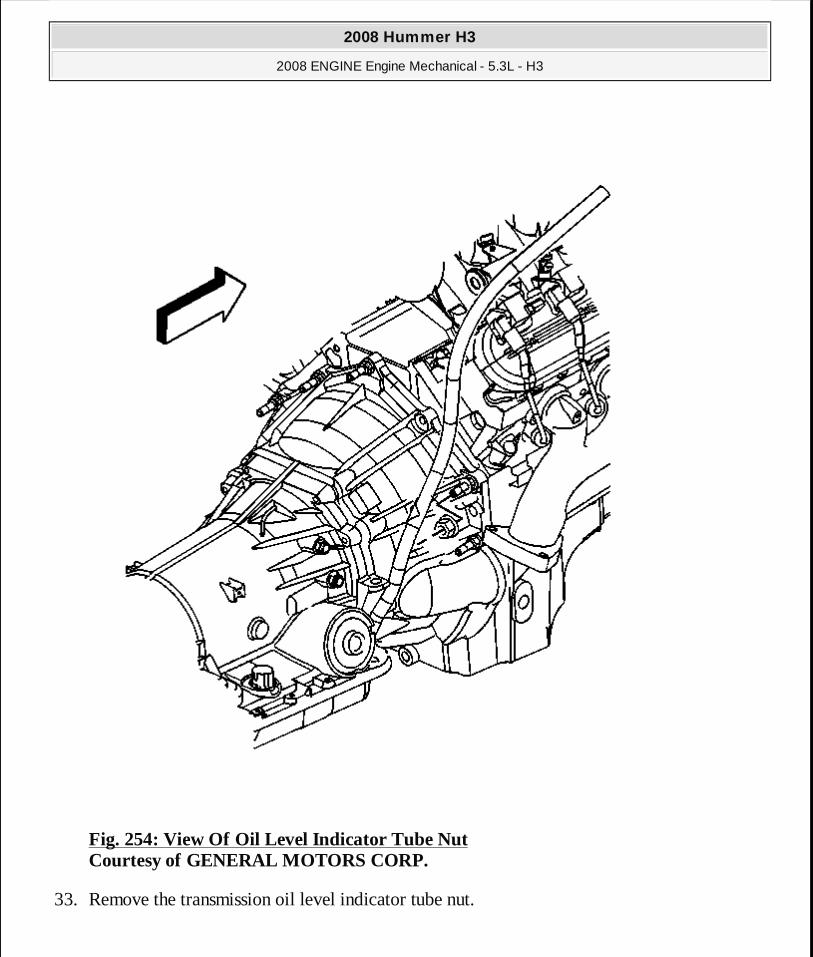
Fig. 254: View Of Oil Level Indicator Tube Nut Courtesy of GENERAL MOTORS CORP.
33. Remove the transmission oil level indicator tube nut.
2008 Hummer H3
2008 ENGINE Engine Mechanical - 5.3L - H3
MY
Sunday, March 29, 2009 10:47:50 PM Page 328 © 2005 Mitchell Repair Information Company, LLC.
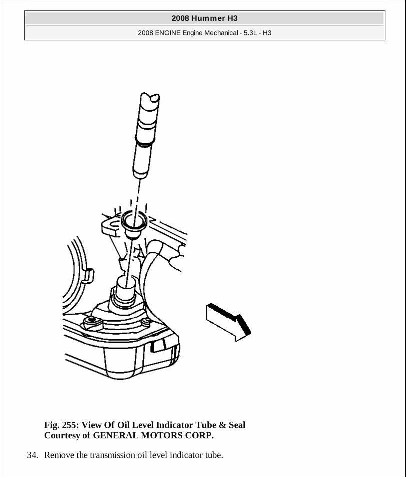
Fig. 255: View Of Oil Level Indicator Tube & Seal Courtesy of GENERAL MOTORS CORP.
34. Remove the transmission oil level indicator tube.
2008 Hummer H3
2008 ENGINE Engine Mechanical - 5.3L - H3
MY
Sunday, March 29, 2009 10:47:50 PM Page 329 © 2005 Mitchell Repair Information Company, LLC.
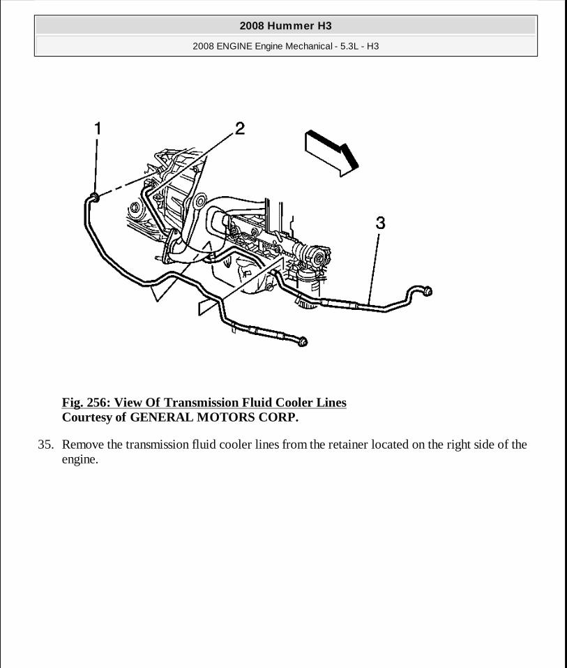
Fig. 256: View Of Transmission Fluid Cooler Lines Courtesy of GENERAL MOTORS CORP.
35. Remove the transmission fluid cooler lines from the retainer located on the right side of the engine.
2008 Hummer H3
2008 ENGINE Engine Mechanical - 5.3L - H3
MY
Sunday, March 29, 2009 10:47:50 PM Page 330 © 2005 Mitchell Repair Information Company, LLC.

Fig. 257: Lower Transmission Bolt/Studs - Right & Left Side Courtesy of GENERAL MOTORS CORP.
36. Remove the lower transmission bolts (1) on the right and left side.
2008 Hummer H3
2008 ENGINE Engine Mechanical - 5.3L - H3
MY
Sunday, March 29, 2009 10:47:50 PM Page 331 © 2005 Mitchell Repair Information Company, LLC.

Fig. 258: Lower Transmission Bolt/Studs Courtesy of GENERAL MOTORS CORP.
37. Remove the lower transmission bolt/studs. 38. Lower the vehicle. 39. Remove the 3 upper transmission bolts/studs (1).
40. Install an engine hoist to J 41798 . See Special Tools. 41. Install a floor jack under the transmission for support. 42. Separate the engine from the transmission. 43. Remove the engine. 44. Install the engine to an engine stand.
2008 Hummer H3
2008 ENGINE Engine Mechanical - 5.3L - H3
MY
Sunday, March 29, 2009 10:47:50 PM Page 332 © 2005 Mitchell Repair Information Company, LLC.