Specification to IEC 62271-200 High-voltage switchgear and ... · IOGP S-620Q: Quality requirements...
42
SPECIFICATION S-620 OCTOBER 2018 Supplementary Specification to IEC 62271-200 High-voltage switchgear and controlgear
Transcript of Specification to IEC 62271-200 High-voltage switchgear and ... · IOGP S-620Q: Quality requirements...
SPECIFICATION
S-620
OCTOBER 2018
Supplementary Specif ication to IEC 62271-200 High-voltage switchgear and controlgear
Revision history
VERSION DATE AMENDMENTS
1.0 October 2018 Issued for Publication
Acknowledgements This IOGP Specification was prepared by a Joint Industry Project 33 Standardization of Equipment Specifications for Procurement organized by IOGP with support by the World Economic Forum (WEF). Disclaimer
Whilst every effort has been made to ensure the accuracy of the information contained in this publication, neither IOGP nor any of its Members past present or future warrants its accuracy or will, regardless of its or their negligence, assume liability for any foreseeable or unforeseeable use made thereof, which liability is hereby excluded. Consequently, such use is at the recipient’s own risk on the basis that any use by the recipient constitutes agreement to the terms of this disclaimer. The recipient is obliged to inform any subsequent recipient of such terms. This publication is made available for information purposes and solely for the private use of the user. IOGP will not directly or indirectly endorse, approve or accredit the content of any course, event or otherwise where this publication will be reproduced.
Copyright notice
The contents of these pages are © International Association of Oil & Gas Producers. Permission is given to reproduce this report in whole or in part provided (i) that the copyright of IOGP and (ii) the sources are acknowledged. All other rights are reserved. Any other use requires the prior written permission of IOGP.
These Terms and Conditions shall be governed by and construed in accordance with the laws of England and Wales. Disputes arising here from shall be exclusively subject to the jurisdiction of the courts of England and Wales.
Supplementary Specification to IEC 62271-200 High-voltage switchgear and controlgear
Page 1 of 39 S-620 October 2018
Foreword
This specification was prepared under a Joint Industry Project 33 (JIP33) “Standardization of Equipment Specifications for Procurement” organized by the International Oil & Gas Producers Association (IOGP) with the support from the World Economic Forum (WEF). Ten key oil and gas companies from the IOGP membership participated in developing this specification under JIP33 Phase 2 with the objective to leverage and improve industry level standardization for projects globally in the oil and gas sector. The work has developed a minimized set of supplementary requirements for procurement, with life cycle cost in mind, based on the ten participating members’ company specifications, resulting in a common and jointly approved specification, and building on recognized industry and/or international standards.
This specification has been developed in consultation with a broad user and supplier base to promote the opportunity to realize benefits from standardization and achieve significant cost reductions for upstream project costs. The JIP33 work groups performed their activities in accordance with IOGP’s Competition Law Guidelines (November 2014).
Recent trends in oil and gas projects have demonstrated substantial budget and schedule overruns. The Oil and Gas Community within the World Economic Forum (WEF) has implemented a Capital Project Complexity (CPC) initiative which seeks to drive a structural reduction in upstream project costs with a focus on industry-wide, non-competitive collaboration and standardization. The vision from the CPC industry is to standardize specifications for global procurement for equipment and packages, facilitating improved standardization of major projects across the globe. While individual oil and gas companies have been improving standardization within their own businesses, this has limited value potential and the industry lags behind other industries and has eroded value by creating bespoke components in projects.
This specification aims to significantly reduce this waste, decrease project costs and improve schedule through pre-competitive collaboration on standardization. This document defines the supplementary requirements to recognized international standard IEC 62271-200 Edition 2.0 2011, High-voltage switchgear and controlgear, which is indispensable for the application of this specification.
Following agreement of the relevant JIP33 work group and approval by the JIP33 Steering Committee, the IOGP Management Committee has agreed to the publication of this specification by IOGP. Where adopted by the individual operating companies, this specification and associated documentation aims to supersede existing company documentation for the purpose of industry-harmonized standardization.
Supplementary Specification to IEC 62271-200 High-voltage switchgear and controlgear
Page 2 of 39 S-620 October 2018
Table of Contents
Foreword ............................................................................................................................................................. 1 Introduction ......................................................................................................................................................... 4 1 General ..................................................................................................................................................... 6
1.1 Scope ............................................................................................................................................. 6 1.2 Normative references ..................................................................................................................... 6
2 Normal and special service conditions (IEC 62271-1 Clause 4) .............................................................. 8 2.1 Normal service conditions (IEC 62271-1 Subclause 4.1) .............................................................. 8 2.2 Special service conditions (IEC 62271-1 Subclause 4.2) .............................................................. 8
3 Terms and definitions (IEC 62271-1 Clause 3) ........................................................................................ 9 4 Ratings (IEC 62271-1 Clause 5) ............................................................................................................ 10
4.1 Rated voltage (Ur) (IEC 62271-1 Subclause 5.2) ......................................................................... 10 4.2 Rated Insulation level (IEC 62271-1 Subclause 5.3) ................................................................... 10 4.4 Rated normal current and temperature rise ................................................................................. 10 4.5 Rated short-time withstand currents (Ik) (IEC 62271-1 Subclause 5.6) ....................................... 10 4.6 Rated peak withstand current (Ip) (IEC 62271-1 Subclause 5.7) ................................................. 11 4.7 Rated durations of short circuit (tk) (IEC 62271-1 Subclause 5.8) ............................................... 11 4.8 Rated supply voltage of closing and opening devices and of auxiliary and control circuits
(Ua) (IEC 62271-1 Subclause 5.9) ............................................................................................... 11 4.101 Ratings of the internal arc classification (IAC) ............................................................................. 11
5 Design and construction (IEC 62271-1 Clause 6) .................................................................................. 11 5.1 Requirements for liquids in switchgear and controlgear (IEC 62271-1 Subclause 6.1) .............. 12 5.3 Earthing of switchgear and controlgear (IEC 62271-1 Subclause 6.3) ........................................ 12 5.4 Auxiliary and control equipment (IEC 62271-1 Subclause 6.4) ................................................... 14 5.9 Low- and high-pressure interlocking and monitoring devices (IEC 62271-1
Subclause 6.10.1) ........................................................................................................................ 17 5.10 Nameplates (IEC 62271-1 Subclause 6.11) ................................................................................ 17 5.11 Interlocking devices (including IEC 62271-1 Subclause 6.12) ..................................................... 17 5.15 Gas and vacuum tightness (IEC 62271-1 Subclause 6.16) ......................................................... 18 5.17 Fire hazard (flammability) (IEC 62271-1 Subclause 6.18) ........................................................... 18 5.18 Electromagnetic compatibility (EMC) (IEC 62271-1 Subclauses 6.19 and 7.9) .......................... 19 5.20 Corrosion (IEC 62271-1 Subclause 6.21) .................................................................................... 19 5.101 Internal arc fault ........................................................................................................................... 19 5.102 Enclosure ..................................................................................................................................... 19 5.103 High voltage compartments ......................................................................................................... 20 5.104 Removable parts .......................................................................................................................... 21 5.106 Labelling and identification ........................................................................................................... 22 5.107 Provisions for future development ............................................................................................... 23 5.108 Main circuit switching devices ...................................................................................................... 23
Supplementary Specification to IEC 62271-200 High-voltage switchgear and controlgear
Page 3 of 39 S-620 October 2018
5.109 Voltage transformers .................................................................................................................... 25 5.110 Current transformers .................................................................................................................... 26 5.111 Surge arrestors............................................................................................................................. 26 5.112 Indication and measuring devices ................................................................................................ 26 5.113 Protection devices ........................................................................................................................ 28 5.114 Cable terminations ....................................................................................................................... 28 5.115 Interfaces ...................................................................................................................................... 29
6 Type tests (IEC 62271-1 Clause 7) ........................................................................................................ 30 6.1 General (IEC 62271-1 Subclause 7.1) ......................................................................................... 30 6.2 Dielectric tests .............................................................................................................................. 31
7 Routine tests (IEC 62271-1 Clause 8).................................................................................................... 31 7.5 Design and visual checks (IEC 62271-1 Subclause 8.6) ............................................................. 31 7.101 Partial discharge measurement ................................................................................................... 31 7.107 ECMS simulation test ................................................................................................................... 32
9 Information to be given with enquiries, tenders and orders ................................................................... 32 10 Transport, storage, installation, operation and maintenance (IEC 62271-1 Clause 11) ........................ 33
10.1 Conditions during transport, storage and installation (IEC 62271-1 Subclause 11.2) ................. 33 11 Safety (IEC 62271-1 Clause 12) ............................................................................................................ 34
11.101 Procedures .............................................................................................................................. 34 12 Influence of the product on the environment (IEC 62271-1 Clause 13) ................................................. 34 Annex DD (new) (normative) Additional requirements for fault current limiter assembly ................................. 35 Bibliography ...................................................................................................................................................... 39
Table 105 – Status indicator colour coding ...................................................................................................... 15 Table 106 – Identification of accessible shutters .............................................................................................. 21 Table 107 – Identification of conductors ........................................................................................................... 23
Supplementary Specification to IEC 62271-200 High-voltage switchgear and controlgear
Page 4 of 39 S-620 October 2018
Introduction
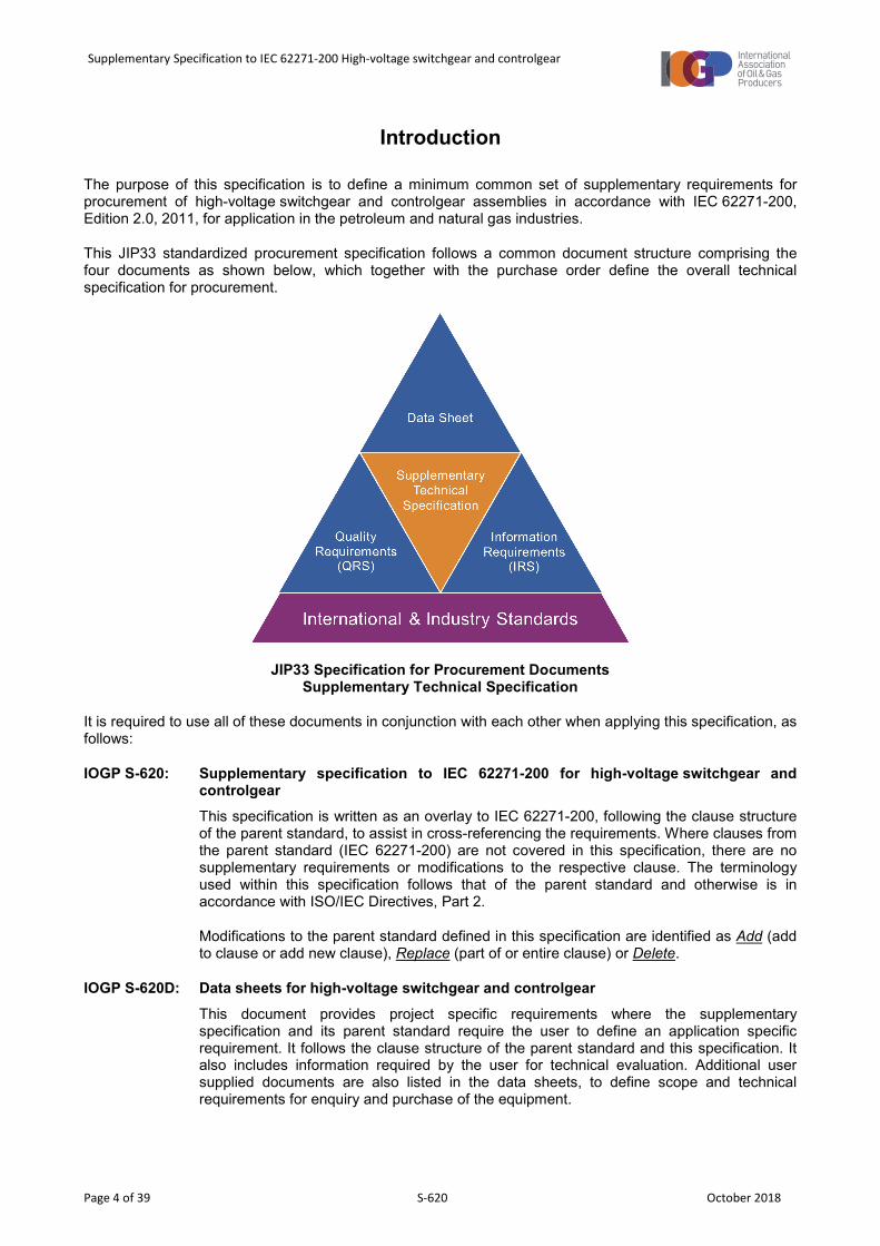
The purpose of this specification is to define a minimum common set of supplementary requirements for procurement of high-voltage switchgear and controlgear assemblies in accordance with IEC 62271-200, Edition 2.0, 2011, for application in the petroleum and natural gas industries.
This JIP33 standardized procurement specification follows a common document structure comprising the four documents as shown below, which together with the purchase order define the overall technical specification for procurement.
JIP33 Specification for Procurement Documents Supplementary Technical Specification
It is required to use all of these documents in conjunction with each other when applying this specification, as follows:
IOGP S-620: Supplementary specification to IEC 62271-200 for high-voltage switchgear and controlgear This specification is written as an overlay to IEC 62271-200, following the clause structure of the parent standard, to assist in cross-referencing the requirements. Where clauses from the parent standard (IEC 62271-200) are not covered in this specification, there are no supplementary requirements or modifications to the respective clause. The terminology used within this specification follows that of the parent standard and otherwise is in accordance with ISO/IEC Directives, Part 2.
Modifications to the parent standard defined in this specification are identified as Add (add to clause or add new clause), Replace (part of or entire clause) or Delete.
IOGP S-620D: Data sheets for high-voltage switchgear and controlgear This document provides project specific requirements where the supplementary specification and its parent standard require the user to define an application specific requirement. It follows the clause structure of the parent standard and this specification. It also includes information required by the user for technical evaluation. Additional user supplied documents are also listed in the data sheets, to define scope and technical requirements for enquiry and purchase of the equipment.

Supplementary Specification to IEC 62271-200 High-voltage switchgear and controlgear
Page 5 of 39 S-620 October 2018
IOGP S-620L: Information requirements for high-voltage switchgear and controlgear This document defines the information requirements, including format, timing and purpose, for information to be provided by the manufacturer. It also defines the specific conditions which must be met for conditional information requirements to become mandatory. The information requirements listed in the IRS have references to the source of the requirement.
IOGP S-620Q: Quality requirements for high-voltage switchgear and controlgear This document includes a conformity assessment system (CAS) which specifies standardized user interventions against quality management activities at four different levels. The applicable CAS level is specified by the user in the data sheets.
The data sheets and IRS are published as editable documents for the user to specify application specific requirements. The supplementary specification and QRS are fixed documents.
Unless defined otherwise in the purchase order, the order of precedence (highest authority listed first) of the documents shall be:
a) regulatory requirements;
b) contract documentation (e.g. purchase order);
c) user defined requirements (equipment data sheets, IRS, QRS);
d) this specification;
e) the parent standard.
Supplementary Specification to IEC 62271-200 High-voltage switchgear and controlgear
Page 6 of 39 S-620 October 2018
1 General
1.1 Scope
Replace first sentence with
This specification amends and supplements IEC 62271-200 Edition 2.0 2011 for the design, materials, fabrication, inspection and testing of AC metal enclosed high-voltage switchgear and controlgear for rated voltages above 1 kV and up to and including 52 kV.
Add to subclause
IEC 62271-200 refers to applicable common specification clauses contained within IEC 62271-1. Since the issue of IEC 62271-1 Edition 2.0 2017, there is a mismatch in the clause numbering used in IEC 62271-200 Edition 2.0 2011. For information, the relevant IEC 62271-1:2017 clause numbers are identified in parentheses in the clause headings of these supplementary requirements.
This specification:
− addresses both air insulated switchgear (AIS) and gas insulated switchgear (GIS) for indoor installation with either fixed, removable or withdrawable parts or combinations thereof;
− for IEC 61850 digital interfaces, establishes minimum default selections from the options given in IEC 62271-3;
− specifies additional requirements for generator circuit-breakers to IEC/IEEE 62271-37-013.
This specification does not cover:
− high-voltage switchgear and controlgear assemblies installed outdoors, other than bus duct and outdoor termination bushings;
− detailed user requirements for electrical control and management systems (ECMSs);
− detailed requirements for optional switchgear condition monitoring systems;
− integrated power semiconductor systems;
− integrated high-voltage variable (adjustable) speed drives to IEC 61800-5;
− ring main units;
− explosion protected “Ex” equipment (incorporating a type of explosion protection covered by the IEC 60079 series of standards);
− direct current (DC) uninterruptible power supply systems for auxiliary power.
1.2 Normative references
Add to subclause
IEC 60051-2 Direct acting indicating analogue electrical measuring instruments and their accessories - Part 2: Special requirements for ammeters and voltmeters
IEC 60051-3 Direct acting indicating analogue electrical measuring instruments and their accessories – Part 3: Special requirements for wattmeters and varmeters
Supplementary Specification to IEC 62271-200 High-voltage switchgear and controlgear
Page 7 of 39 S-620 October 2018
IEC 60092-101 Electrical installations in ships - Part 101: Definitions and general requirements
IEC 60099-4 Surge arresters – Part 4: Metal-oxide surge arresters without gaps for a.c. systems
IEC 60204-1 Safety of machinery – Electrical equipment of machines – Part 1: General requirements
IEC 60255 Electrical relays – All parts as applicable
IEC 60269-1 Low-voltage fuses – Part 1: General requirements
IEC 60269-2 Low-voltage fuses – Part 2: Supplementary requirements for fuses for use by authorized persons (fuses mainly for industrial application) – Examples of standardized systems of fuses A to K
IEC 60282-1 High-voltage fuses – Part 1: Current-limiting fuses
IEC 60364-4-41 Low-voltage electrical installations – Part 4-41: Protection for safety – Protection against electric shock
IEC 60644 Specifications for high-voltage fuse-links for motor circuit applications
IEC 60688 Electrical measuring transducers for converting A.C. and D.C. electrical quantities to analogue or digital signals
IEC TS 60815-1 Selection and dimensioning of high-voltage insulators intended for use in polluted conditions – Part 1: Definitions, information and general principles
IEC 60947-5-1 Low-voltage switchgear and controlgear – Part 5-1: Control circuit devices and switching elements – Electromechanical control circuit devices
IEC 61000-3-6 Electromagnetic compatibility (EMC) – Part 3-6: Limits – Assessment of emission limits for the connection of distorting installations to MV, HV and EHV power systems
IEC 61243-5 Live working – Voltage detectors – Part 5: Voltage detecting systems (VDS)
IEC 61511-1 Functional safety – Safety instrumented systems for the process industry sector – Part 1: Framework, definitions, system, hardware and application programming requirements
IEC 61554 Panel Mounted Equipment – Electrical Measuring Instruments – Dimensions for Panel Mounting
IEC 61869-1 Instrument transformers – Part 1: General requirements
IEC 61869-2 Instrument transformers – Part 2: Additional requirements for current transformers
IEC 61869-3 Instrument transformers – Part 3: Additional requirements for inductive voltage transformers
IEC 61869-5 Instrument transformers – Part 5: Additional requirements for capacitor voltage transformers
IEC 61869-6 Instrument transformers – Part 6: Additional general requirements for low-power instrument transformers
IEC 61869-10 Instrument transformers – Part 10: Additional requirements for low-power passive current transformers
IEC 61869-11 Instrument transformers – Part 11: Additional requirements for low power passive voltage transformers
IEC 61892-3 Mobile and fixed offshore units – Electrical installations – Part 3: Equipment
IEC 62052-11 Electricity metering equipment (a.c.) – General requirements, tests and test conditions – Part 11: Metering equipment
IEC TR 62061-1 Guidance on the application of ISO 13849-1 and IEC 62061 in the design of safety-related control systems for machinery
Supplementary Specification to IEC 62271-200 High-voltage switchgear and controlgear
Page 8 of 39 S-620 October 2018
IEC 62271-1:2017 High-voltage switchgear and controlgear – Part 1: Common specifications for alternating current switchgear and controlgear
IEC 62271-3 High-voltage switchgear and controlgear – Part 3: Digital interfaces based on IEC 61850
IEC 62271-200:2011 High-voltage switchgear and controlgear – Part 200: AC metal-enclosed switchgear and controlgear for rated voltages above 1 kV and up to and including 52 kV
IEC/IEEE 62271-37-013 High-voltage switchgear and controlgear – Part 37-013: Alternating current generator circuit-breakers
IEC 62271-102 High-voltage switchgear and controlgear – Part 102: High-voltage alternating current disconnectors and earthing switches
IEC 62271-106 High-voltage switchgear and controlgear – Part 106: Alternating current contactors, contactor-based controllers and motor starters
IEC 62271-206 High-voltage switchgear and controlgear – Part 206: Voltage presence indicating systems for rated voltages above 1 kV and up to and including 52 kV
ISO 7010 Graphical symbols – Safety colours and safety signs – Registered safety signs
2 Normal and special service conditions (IEC 62271-1 Clause 4)
Add new subclause heading
2.1 Normal service conditions (IEC 62271-1 Subclause 4.1)
Add new subclause
2.1.2 Indoor switchgear and controlgear (IEC 62271-1 Subclause 4.1.2)
The normal service conditions as described in subclause 4.1.2 of IEC 62271-1 shall be applied unless supplementary indoor special service conditions are defined as required by the user in the data sheets. All components shall have the user defined ratings after de-rating factors (if any) for the specified service conditions.
Where offshore location is defined by the user in the data sheets, the maximum air temperature shall be 40 °C unless a higher figure of 45 °C is defined by the user in the data sheets.
Add new subclause
2.1.3 Outdoor switchgear and controlgear (IEC 62271-1 Subclause 4.1.3)
If high-voltage bus duct runs that extend outdoors are required, the normal service conditions, as described in subclause 4.1.3 of IEC 62271-1 shall be applied to the outdoor portion of bus ducts and outdoor bushings, unless supplementary outdoor special service conditions are defined as required by the user in the data sheets.
Add new subclause heading
2.2 Special service conditions (IEC 62271-1 Subclause 4.2)
Add new subclause
2.2.3 Exposure to pollution (IEC 62271-1 Subclause 4.2.3)
Unless exposed to polluting special service conditions as defined by the user in the data sheets, high-voltage switchgear and controlgear assemblies shall be suitable for use in an indoor environment with a “very light” site pollution severity.

Supplementary Specification to IEC 62271-200 High-voltage switchgear and controlgear
Page 9 of 39 S-620 October 2018
Add new subclause
2.2.7 Other parameters (IEC 62271-1 Subclause 4.2.7)
High-voltage switchgear and controlgear shall operate under other parameters of special service conditions if defined by the user in the data sheets.
NOTE IOGP S-620D line items 2.2.7 a) to l) within section “Special service conditions - other parameters” align with the IEC 61439-1 special service conditions requirements for low-voltage switchgear and controlgear assemblies.
3 Terms and definitions (IEC 62271-1 Clause 3)
Add to subclause
3.10.136 bus coupler a functional unit that contains a mechanical switching device, which electrically connects together two bus sections
3.10.137 bus section a number of functional units normally connected together in service by a physically continuous main busbar
3.10.138 circuit schedule developed by the user and defining the required mechanical switching device, duty, load details, and other individual circuit functions
3.10.139 data sheets developed by the user summarizing the characteristics, performance and constructional requirements for the design and selection of the equipment
3.10.140 factory acceptance test (FAT) performance of routine tests and any user agreed additional functional tests on the assembled high-voltage switchgear and controlgear and associated equipment, with user agreed acceptance of the test results to permit release of the equipment from the factory
3.10.141 functional logic control logic embedded in intelligent electronic devices (IED) or protection relays, that is developed by the manufacturer to implement the requirements of the user diagrams and associated protection relay settings
3.10.142 manufacturer organization taking the responsibility for the completed high-voltage switchgear and controlgear assemblies and equipment with associated interconnections, accessories, enclosures and supporting structures
NOTE The assembly manufacturer may be a different organization to the original equipment manufacturer organization that has carried out the original design and the associated verification of an assembly or main circuit components within an assembly.
3.10.143 user diagrams developed by the user, defines the functional requirements for a given type or scheme of circuit, protection, control, metering etc. such as switchgear single line diagrams, and circuit and wiring diagrams. Used during the development and design stage of a project

Supplementary Specification to IEC 62271-200 High-voltage switchgear and controlgear
Page 10 of 39 S-620 October 2018
4 Ratings (IEC 62271-1 Clause 5)
4.1 Rated voltage (Ur) (IEC 62271-1 Subclause 5.2)
Add to subclause
Unless defined otherwise by the user in the data sheets, the high-voltage switchgear and controlgear assembly shall be suitable for operation with power system supply voltage harmonic content not exceeding 6,5 % total harmonic distortion (THD), without damaging effect.
NOTE The THD values of 6,5 % is in accordance with IEC TR 61000-3-6:2008, Table 2 planning levels.
4.2 Rated Insulation level (IEC 62271-1 Subclause 5.3)
Add to subclause
The rated insulation level of the high-voltage switchgear and controlgear shall be as defined by the user in the data sheets, selected from the Range I values given in Table 1 and Table 2 of IEC 62271-1.
Main busbars in air filled compartments and their branches to switching devices and voltage transformers, shall be insulation covered.
4.4 Rated normal current and temperature rise
4.4.1 Rated normal current (Ir) (IEC 62271-1 Subclause 5.5)
Add to subclause
Rated normal currents of 3150 A and below for AIS assemblies, and 2500 A and below for GIS assemblies, shall not depend on forced ventilation, and shall be continuous ratings after de-rating for the specified service conditions. The main busbars shall be rated for the normal current throughout the entire length of the high-voltage switchgear and controlgear assembly. The use of forced cooling is subject to agreement between the user and the manufacturer.
Busbars in air insulated or gas-air mixture filled compartments shall be manufactured from hard drawn, high conductivity electrolytic copper unless aluminium is defined as required by the user in the data sheets.
4.4.2 Temperature rise (covered in IEC 62271-1 Subclauses 4.1.2 and 4.2.4)
Add to subclause
The high-voltage switchgear and controlgear assembly shall comply with temperature rise limitations for the maximum design air temperature defined by the user in the data sheets.
4.5 Rated short-time withstand currents (Ik) (IEC 62271-1 Subclause 5.6)
4.5.102 Rated short-time phase to earth withstand current (Ike)
Replace second sentence with
The value of rated short-time phase to earth withstand current (Ike) shall be at least 87 % of the rated short-time withstand current (Ik) of the main circuit, unless defined otherwise by the user in the data sheets.
Supplementary Specification to IEC 62271-200 High-voltage switchgear and controlgear
Page 11 of 39 S-620 October 2018
4.6 Rated peak withstand current (Ip) (IEC 62271-1 Subclause 5.7)
4.6.102 Rated peak phase to earth withstand current (Ipe)
Replace second sentence with
The value of rated peak phase to earth withstand current (Ipe) shall be at least 87 % of the rated peak withstand current (Ip) of the main circuit, unless defined otherwise by the user in the data sheets.
4.7 Rated durations of short circuit (tk) (IEC 62271-1 Subclause 5.8)
4.7.102 Rated duration of phase to earth short circuit (tke)
Replace second sentence with
The value of rated short-time phase to earth withstand current (IKe) shall be equal to the rated duration of short circuit (tk) of the main circuit, unless defined otherwise by the user in the data sheets.
4.8 Rated supply voltage of closing and opening devices and of auxiliary and control circuits (Ua) (IEC 62271-1 Subclause 5.9)
Add to subclause
The rated supply voltage of auxiliary and control circuits shall be as defined by the user in the data sheets, selected from the values given in Table 6 and from line items 1 to 5 in Table 7 of IEC 62271-1.
4.101 Ratings of the internal arc classification (IAC)
4.101.2 Types of accessibility
Add to subclause
Accessibility shall be Accessibility Type A unless defined otherwise by the user in the data sheets.
Add to subclause
All equipment shall be accessible from the front, except for cable termination chambers. Requirements for front or rear access to cable termination chambers shall be as defined by the user in the data sheets. All components in back-to-wall mounted high-voltage switchgear and controlgear assemblies shall be accessible from the front only.
5 Design and construction (IEC 62271-1 Clause 6)
Add new subclause
5.0.101 General
High-voltage switchgear and controlgear assemblies shall be suitable for securing to longitudinal runs of channels flush with the floor surface, unless defined otherwise by the user in the data sheets.
When marine class or offshore installation is identified by the user as a requirement in the data sheets, the equipment shall conform with the stated requirements for high-voltage switchgear and controlgear assemblies as defined in IEC 60092-101 and IEC 61892-3 respectively.
Supplementary Specification to IEC 62271-200 High-voltage switchgear and controlgear
Page 12 of 39 S-620 October 2018
Add new subclause
5.0.102 Technology readiness and obsolescence
The high-voltage switchgear and controlgear assemblies, excluding electronic components, shall have a design and post factory acceptance test (FAT) supported lifetime of at least 20 years under the defined service conditions.
The manufacturer shall have an obsolescence management plan in accordance with a recognized system for all high-voltage switchgear and controlgear assembly components, as defined by the user in the data sheets.
NOTE IEC 62402 is an example of an obsolescence management guide; refer to [17] of Bibliography.
The use of switchgear and controlgear assemblies and sub-components with less than 3 years proven operational service shall be subject to agreement between the user and the manufacturer.
Add new subclause
5.0.103 Dependability of materials and parts
Unless longer service periods are defined as required by the user in the data sheets, high-voltage switchgear and controlgear assemblies and functional units shall be designed for continuous operation at full load under the normal service conditions for at least 45 000 hours (5 years). During this period, the main busbars and the distribution busbars (dropper system) shall not need to be de-energized for maintenance or inspection.
The manufacturer shall identify components within the installation, operation and maintenance manual that are not suitable for 5 years continuous operation without inspection or replacement under the service conditions as defined in the data sheets.
5.1 Requirements for liquids in switchgear and controlgear (IEC 62271-1 Subclause 6.1)
Add to subclause
Liquids shall not be used as a switching or as an insulating medium unless agreed between the user and the manufacturer for use in specialist items.
5.3 Earthing of switchgear and controlgear (IEC 62271-1 Subclause 6.3)
5.3.101 Earthing of the high-voltage conductive parts
Add to subclause
Facilities for earthing the high-voltage conductive parts shall be provided on the incoming side of each supply (generator/transformer) circuit and on the outgoing (cable) side of each feeder/load circuit as shown in Figures 101 to 106 appropriate to the provided loss of service continuity (LSC) category.
Facilities for earthing the high-voltage conductive parts of each bus section shall be provided via the incoming supply functional units, or via dedicated busbar earthing compartments.
Switches for earthing of high-voltage conductive parts shall have a minimum classification for short-circuit making of Class E1, as specified in subclause 5.102 of IEC 62271-102:2003 unless defined otherwise by the user in the data sheets.
Switches for earthing of high-voltage conductive parts shall have a minimum mechanical endurance Class M0, as specified in subclause 5.106 of IEC 62271-102:2003 unless defined otherwise by the user in the data sheets.
Supplementary Specification to IEC 62271-200 High-voltage switchgear and controlgear
Page 13 of 39 S-620 October 2018
Earthing devices shall be arranged for manually initiated operation only, from operator locations as defined by the user in the data sheets.
NOTE Contactor feeder functional units serving circuits without back-feed may have outgoing circuit earthing automatically applied following a manually initiated isolation action or functional unit withdrawal.
Add new subclause
5.3.101.1 Earthing for withdrawable type switchgear
Facilities for incoming and outgoing circuit earthing shall be via the functional unit circuit-breaker or by an integrally mounted three-phase earthing switch.
Facilities for busbar earthing shall be:
− via the functional unit circuit-breaker of each supply (generator/transformer) circuit on the busbar side;
− by an integrally mounted three-phase earthing switch; or
− by a withdrawable truck mounted busbar earthing switch.
For busbar earthing via a withdrawable truck mounted earthing switch, the manufacturer shall provide one earthing truck for each high-voltage switchboard assembly. It shall not be possible to insert the withdrawable busbar earthing device into circuit positions other than the incoming supply functional units or dedicated busbar earthing compartments.
Earthing devices shall include the following safety and locking and functions:
a) It shall only be possible to apply an earth connection to high-voltage conductive parts when the main circuit switching device within the same functional unit, is isolated and not in the service (circuit) position;
b) Insertion of a withdrawable main circuit switching device into the service (circuit) position shall not be possible when the earthing provision within the same functional unit is applied.
Add new subclause
5.3.101.2 Earthing for non-withdrawable (fixed) type switchgear
Facilities for incoming and outgoing circuit earthing shall be via the functional unit circuit-breaker, or by an integrated three-position switch.
The bus coupler functional unit shall incorporate the busbar earthing system and shall provide integrated facilities for earthing each bus section.
Earthing switches shall include the following safety and locking functions:
a) It shall only be possible to apply an earth to high-voltage conductive parts when the main circuit switching device within the same functional unit is isolated; and
b) De-isolation and closing of the main circuit switching device shall not be possible when the earthing provision within the same functional unit is applied.
Supplementary Specification to IEC 62271-200 High-voltage switchgear and controlgear
Page 14 of 39 S-620 October 2018
5.3.102 Earthing of the enclosure
Add to subclause
A hard-drawn high conductivity copper earth bar shall be provided along the full length of each high-voltage switchgear and controlgear assembly sized in accordance with subclause 5.3.105 of IEC 62271-200, with provision for bolted connection of an external earth cable connection at each end. This earth bar shall be extended with the same cross section to each high-voltage external circuit termination compartment.
Add new subclause
5.3.106 Voltage detecting and indicating systems
Where defined as required by the user in the data sheets, a capacitive three-phase voltage detecting system to confirm both the presence and absence of main circuit voltage in accordance with IEC 61243-5 shall be provided. The voltage detectors on each functional unit shall be installed adjacent to the connection (cable) compartment on all incoming circuits and outgoing feeders, and on the front of the bus coupler panels for each bus section.
Where defined as required by the user in the data sheets, a capacitive three-phase voltage presence indicating system to confirm the presence of main circuit voltage in accordance with IEC 62271-206 shall be provided. The voltage indicators on each functional unit shall be installed adjacent to the connection (cable) compartment on all incoming circuits and outgoing feeders, and on the front of the bus coupler panels for each bus section.
Voltage indicating/detection systems shall be fitted with measuring test points which permit connection of an external phase comparator (phasing-out) instrument.
5.4 Auxiliary and control equipment (IEC 62271-1 Subclause 6.4)
Add new subclause
5.4.1 General (IEC 62271-1 Subclause 6.4.1)
Each incoming auxiliary and control power supply shall be monitored and initiate an alarm on loss of availability.
Within each functional unit, the auxiliary and control supplies shall be distributed into separate circuits. Each separate circuit shall be protected by miniature circuit-breakers (MCBs), fitted with an auxiliary contact to initiate an MCB trip remote alarm. Means shall be provided to lock the MCB operating mechanism in the open position.
NOTE IEC 60898-1 locking provision may be by the insertion of proprietary third party pad lockable devices; refer to [15] of Bibliography.
Functional unit control circuits are to be arranged such that operation or failure of the tripping circuit supply shall inhibit main circuit-breaker/contactor closure and initiate local and remote alarms.
Low-voltage fuses shall conform to IEC 60269-1 and 2.
Functional unit auxiliary and control circuits that derive their power supply from an external source shall be clearly identified and for circuits operating at above safety extra low voltage, be connected via removable links or isolation facilities.

Supplementary Specification to IEC 62271-200 High-voltage switchgear and controlgear
Page 15 of 39 S-620 October 2018
Add new subclause
5.4.1.1 Auxiliary components
Unless shown otherwise on the user diagrams, protection, control, indication, metering, supervisory Input/Output (I/O) and communication functions shall be provided by multifunction IEDs. Any user required front of panel discrete components shall be proved as shown on the user diagrams. IED human machine interface (HMI) and discrete items of the same function shall be arranged in a consistent physical position across functional units.
Plug-in type auxiliary components shall be provided with retaining clips.
Add new subclause
5.4.1.2 Actuators and indication
The colour and marking of actuators (push buttons) shall be in accordance with IEC 60204-1. Where colour is used to define function, start/on actuators shall be green and stop/off actuators, red.
On discrete indication components or on colour HMI screens, colour coding of status indication shall be in accordance with Table 105, unless defined otherwise by the user in the data sheets.
Table 105 – Status indicator colour coding
Colour Meaning High-voltage - Assembly Application
Safety of persons or environment
Circuit-breaker Motor starter / contactor feeder
Red Danger Closed (On) Running (On)
Yellow Warning/caution Tripped Tripped
Green Safe Open (Off) Stopped (Off)
Blue Mandatory significance Trip circuit healthy (or unhealthy)
Not applicable
White No specific meaning assigned
Voltage indication (Heater On)
Motor heater on
NOTE Colours detailed in the table are in accordance with IEC 60073; refer to [11] of the Bibliography
NOTE This requirement does not apply to IEDs or protection relays with a suite of status LEDs which are all the same colour.
Discrete indication lamps shall be long life light emitting diode (LED) type and shall operate at the same voltage for interchangeability purposes, exceptions being indicating lights directly connected in heater supply circuits.
Add new subclause
5.4.1.3 Auxiliary contacts
Auxiliary and control circuit connections on withdrawable devices shall be fitted with either self-aligning plug and socket contacts, or a multi-conductor cable with plug and socket arrangement.
Every high-voltage switching device shall have sets of volt free auxiliary contacts, of quantity as defined on the user diagrams, for remote alarm and indication, directly activated by the main operating mechanism, Class 2 in accordance with Table 8 of IEC 62271-1.
Supplementary Specification to IEC 62271-200 High-voltage switchgear and controlgear
Page 16 of 39 S-620 October 2018
Where slave relays are used to obtain the required quantity of auxiliary contacts, one set being normally open and the other set normally closed, these contacts shall be terminated at the low-voltage control compartment.
5.4.3 Components installed in enclosures (IEC 62271-1 Subclause 6.4.3)
5.4.3.4 Requirements for auxiliary and control circuit components (IEC 62271-1 Subclause 6.4.3.4)
5.4.3.4.1 General (IEC 62271-1 Subclause 6.4.3.4.1)
Add to subclause
Control and auxiliary devices shall conform to IEC 60947-5-1 with thermal/breaking capacities of contacts rated for their application and conforming to Table 1 and Annex A of IEC 60947-5-1:2016. The utilization categories and minimum characteristics shall be:
a) AC 15 for AC applications;
b) DC 13 for DC applications;
c) rated operational currents (Ie): 5A 230V AC; 1A 110V DC;
d) service cycles: 120 cycles/hour (each relay);
e) mechanical duration class: 1 (in millions of operation cycles).
5.4.3.4.6 Heating elements (IEC 62271-1 Subclause 6.4.3.4.6)
Add to subclause
If defined as required by the user in the data sheets, low-voltage auxiliary and control component compartments and air insulated high-voltage connection (cable) compartments shall be provided with space heaters for anti-condensation prevention.
Space heaters internal to the high-voltage switchgear and controlgear assemblies shall:
− be designed for operation at the voltage as defined by the user in the data sheets;
− have a minimum degree of protection of IP2X;
− include an additional mechanical guard where the heater surface temperature exceeds 60 °C.
The heating system of each bus section of the high-voltage switchgear and controlgear assembly shall:
− be separately supplied from a remote source;
− be provided with a MCB and 30 mA residual current device (RCD) or residual current circuit-breaker with overcurrent protection (RCBO), with “loss of supply” volt free contact wired to terminals for remote supervision;
− be controlled by a thermostat or hygrostat, as defined by the user in the data sheets;
− be fitted with a manual switch to bypass the thermostat/hygrostat control, if defined in the user diagrams.

Supplementary Specification to IEC 62271-200 High-voltage switchgear and controlgear
Page 17 of 39 S-620 October 2018
If defined as required by the user in the data sheets, motor starter functional units shall be fitted with auxiliary circuits to supply remote space heaters within the high-voltage motors.
Auxiliary circuits for remote motor space heaters shall:
− supply the motor space heaters at the voltage as defined by the user in the data sheets;
− be energized whenever the motor starter functional unit main circuit switching device is open, when either in the service or the test position;
Additional requirements for isolation of the remote motor space heater supplies and by-pass of the heater controls when the main circuit switching device is isolated shall be as defined on the user diagrams.
The remote motor space heater auxiliary supply of each bus section of the high-voltage switchgear and controlgear assembly shall:
− be separately supplied from a remote source;
− be distributed from dedicated motor space heater auxiliary bus wiring;
− be provided with a MCB and 30 mA residual current device (RCD) or residual current circuit-breaker with overcurrent protection (RCBO), with “loss of supply” volt free contact wired to terminals for remote supervision.
5.9 Low- and high-pressure interlocking and monitoring devices (IEC 62271-1 Subclause 6.10.1)
Add to subclause
For GIS assemblies, local and remote indication and alarm capability shall be provided. The method of local pressure indication shall be as defined by the user in the data sheets.
5.10 Nameplates (IEC 62271-1 Subclause 6.11)
Add to subclause
The high-voltage switchgear and controlgear assembly nameplate shall contain other legally required regional markings, where applicable.
5.11 Interlocking devices (including IEC 62271-1 Subclause 6.12)
Add to subclause
Where interlocks between main circuit switching devices and associated earthing switches and “upstream” or “downstream” switchgear assemblies are required, they shall be either mechanical or electrical type to fulfil the interlocking function as defined in the user diagrams.
Busbar section earthing switches shall be mechanically or electrically interlocked to prevent closure, until all incomers, interconnectors or possible back-feed circuits are secured in an out-of-service position.
Facilities for padlocking shall be provided for the following as a minimum:
a) high-voltage compartment doors closed;
b) disconnectors (isolators) open or circuit-breakers in the isolated position;
c) safety shutters closed (withdrawable items only with separate facility for busbar and circuit shutters);

Supplementary Specification to IEC 62271-200 High-voltage switchgear and controlgear
Page 18 of 39 S-620 October 2018
d) earth switches closed or circuit-breakers in the earthed position;
e) earth switches open or circuit-breakers blocked from being in the earthed position;
f) access to isolation and earth switch operating mechanisms;
g) each withdrawable main circuit device compartment shall be provided with a padlockable mechanical interlock to prevent reinsertion of a main circuit device.
Padlocking or key locking shall be provided for switching device control circuit local/remote selector switches in all positions.
5.15 Gas and vacuum tightness (IEC 62271-1 Subclause 6.16)
Add new subclause
5.15.1 General (IEC 62271-1 Subclause 6.16.1)
For AIS assemblies, other than for earth switches and isolators, air shall not be used as a switching medium unless defined otherwise by the user in the data sheets.
For GIS assemblies, compartments where SF6 is used as the switching medium, gas barriers shall be included to prevent the migration of arc degradation products beyond the switching compartment, and to uphold the functional unit LSC category during switching compartment inspection or replenishment of the SF6.
Add new subclause
5.15.2 Controlled pressure systems for gas (IEC 62271-1 Subclause 6.16.2)
For GIS assemblies, controlled pressure systems shall not be used unless defined otherwise by the user in the data sheets.
Add new subclause
5.15.3 Closed pressure systems for gas (IEC 62271-1 Subclause 6.16.3)
Replace first list item with
− for SF6 and SF6 mixtures, 0,1 % per year;
5.17 Fire hazard (flammability) (IEC 62271-1 Subclause 6.18)
Add to subclause
Where defined as required by the user in the data sheets, auxiliary and control circuit insulation shall be low smoke, zero halogen content.
The manufacturer shall state the fire resistant and self-extinguishing properties of the materials used.
NOTE Properties can be demonstrated by testing to internationally recognized standards such as IEC 60695-1-10 and 12; refer to [13] and [14] of Bibliography.
Supplementary Specification to IEC 62271-200 High-voltage switchgear and controlgear
Page 19 of 39 S-620 October 2018
5.18 Electromagnetic compatibility (EMC) (IEC 62271-1 Subclauses 6.19 and 7.9)
Add to subclause
The EMC requirements specified in IEC 62271-1 subclause 7.9.1.2 onwards and Annex J.5 shall be satisfied.
5.20 Corrosion (IEC 62271-1 Subclause 6.21)
Add to subclause
Unless defined otherwise by the user in the data sheets, the manufacturer’s standard painting and corrosion protection system for the service conditions defined in the data sheets shall be used.
Unless defined otherwise by the user in the data sheets, the manufacturer’s standard colour finish shall be used.
5.101 Internal arc fault
Add to subclause
The internal arc classification (IAC) of the switchgear shall be FLR unless defined otherwise by the user in the data sheets.
The internal arc type test for the high-voltage switchgear shall be for a rated three-phase arc fault current (IA) value not less than the defined rated short-time withstand current (Ik) for a minimum arc fault duration of 0,5 s, unless defined for a longer duration by the user in the data sheets. The switchgear shall be provided with means to safely direct and exhaust gases resulting from an internal arc flash.
Partitions shall be provided at bus coupler boundaries to prevent an internal arc in one bus section propagating to other bus sections.
Where defined as required in the user diagrams, an internal arc fault detection and active protection system to reduce incident energy levels, shall be provided and integrated into the high-voltage switchgear and controlgear assembly.
5.102 Enclosure
5.102.1 General
Replace second sentence of first paragraph with
The floor surface below the installed high-voltage switchgear and controlgear shall not be considered as being part of the enclosure unless defined otherwise by the user in the data sheets.
Replace first sentence of fourth paragraph with
When the metal enclosed high-voltage switchgear and controlgear is installed, the enclosure shall provide at least the degree of protection IP3XW. The supplementary “W” weather conditions shall be taken as water dripping from above the assembly.
NOTE The supplementary “W” requirement is not subject to verification by testing.
Supplementary Specification to IEC 62271-200 High-voltage switchgear and controlgear
Page 20 of 39 S-620 October 2018
5.102.2 Covers and doors
Add to subclause after second paragraph
Hinged doors which can open at least 95° around their vertical axis shall not be obstructed by adjacent equipment or doors on the high-voltage switchgear and controlgear assembly.
Extraneous conductive parts such as doors or covers which have mounted electrical components (lamps, push buttons, etc.) shall be provided with supplemental equipotential bonding, in accordance with IEC 60364-4-41.
Door restraints shall be provided for securing doors in the open position:
− when placed on floating offshore, mobile offshore or marine installations; and
− when defined as required by the user in the data sheets, on low-voltage compartment doors.
Add to subclause after fourth paragraph
Covers or doors that give access to compartments which do not contain any high-voltage parts (e.g. low-voltage control compartments, or mechanism compartments), shall have tool based or procedure based accessibility, as defined by the user in the data sheets.
NOTE Compartments secured by tumbler lock common keys or panel keys (e.g. 7 mm square, 8 mm triangle or similar) are regarded as procedure based access.
Replace the first sentence for the procedure-based accessible compartments subclause with
These compartments shall be provided with provision for locking by padlocks.
Add to the end of subclause
Covers or doors that give access to high-voltage compartments shall have accessibility as defined by the user in the data sheets.
5.103 High voltage compartments
5.103.1 General
Add to subclause after first paragraph
For GIS assemblies, the LSC category shall be LSC2.
For AIS assemblies, the LSC category shall be:
− for circuit-breaker functional units, LSC2B;
− for contactor feeder functional units serving circuits without back-feed, a minimum of LSC2A.
Add to subclause after fourth paragraph
Busbar compartments shall not contain more than one busbar section. Busbar risers on different sides of a bus coupler switching device shall be in separate compartments.

Supplementary Specification to IEC 62271-200 High-voltage switchgear and controlgear
Page 21 of 39 S-620 October 2018
5.103.2 Fluid filled compartments (gas or liquid)
5.103.2.3 Tightness
Add to subclause after third paragraph
For GIS assemblies, indication when the pressure has fallen below the minimum functional level shall be provided locally, and with provision made for remote indication of the alarm state.
5.103.2.4 Pressure relief of fluid filled compartments
Add to subclause
For GIS assemblies, each fluid filled compartment shall be equipped with a pressure relief device.
NOTE “Compartment” in the context used above could be more than one compartment, connected together in one pressure system.
5.103.3 Partitions and shutters
5.103.3.1 General
Replace first paragraph with
Partitions and shutters shall provide at least the degree of protection IP2X according to Table 7 of IEC 62271-1, unless defined otherwise by the user in the data sheets.
5.103.3.2 Metallic partitions and shutters
Add to subclause
For withdrawable parts, any revealed accessible shutters that prevent access to normally live parts, shall be marked with ISO 7010 W012 electrical hazard warning triangle signs with supplemental text stating the numerical value of the circuit voltage.
For withdrawable parts, each three-phase set of accessible shutters for main circuit conductors shall be capable of being individually manually opened for inspection or testing purposes.
For withdrawable parts, accessible shutters shall be identified in accordance with Table 106, unless alternative or additional languages are defined as required in 5.106 for labelling and identification.
Table 106 – Identification of accessible shutters
5.104 Removable parts
Add to subclause
Where defined as required by the user in the data sheets, facilities for remote testing of withdrawable main circuit units shall be provided by means of extension umbilicals or specific test modules.
Equipment Text
Busbars BUSBAR
Incoming unit supply circuit SUPPLY
Outgoing unit feeder cables CIRCUIT

Supplementary Specification to IEC 62271-200 High-voltage switchgear and controlgear
Page 22 of 39 S-620 October 2018
Withdrawable main circuit units shall only be interchangeable between positions of same electrical function and duty.
Add new subclause
5.106 Labelling and identification
The language used on all devices, labels, plates and notices shall be English, unless alternative or additional languages are defined as required by the user in the data sheets. Graphical symbols, safety colours, safety signs and registered safety signs shall be in accordance with ISO 7010. Text-only warning labels shall have white characters on a red background. All other labels shall have black characters on a white background.
Each high-voltage switchgear and controlgear assembly shall be provided with an identification number label, fixed on the front of the assembly which shall contain the user defined switchgear tag number.
Any main circuit hardware or equipment that is withdrawable shall be fitted with a panel number locator label to facilitate re-insertion to the correct functional unit.
Add new subclause
5.106.1 Circuit labels
Each functional unit shall have a front of panel circuit designation label and for assemblies with rear access, an identical label repeated at the rear. The label shall contain the following information as defined in the circuit schedule:
a) functional unit compartment location (number);
b) tag number of connected equipment;
c) service description of connected equipment; and
d) circuit rating or motor kW rating.
Circuit designation labels shall be secured with non-corrodible screws or other demountable fixing system.
Add new subclause
5.106.2 Identification of the conductors of main and auxiliary circuits
The identification of the conductors in main and auxiliary circuits shall be in accordance with Table 107, unless defined otherwise by the user in the data sheets.
It is not a mandatory requirement to colour wiring insulation or main circuit conductors, but where colour is used as an identifier, these colours shall be applied.
In regions where national standards mandate other identification colour schemes, these shall be applied.

Supplementary Specification to IEC 62271-200 High-voltage switchgear and controlgear
Page 23 of 39 S-620 October 2018
Table 107 – Identification of conductors
Conductor Main circuit marking Auxiliary circuit marking
Supplementary colour marking. when used
AC Circuits
Phase 1 L1 L1 Brown
Phase 2 L2 L2 Black
Phase 3 L3 L3 Grey
Neutral
N Blue
Protective earth PE and/or earth symbol PE and/or earth symbol Yellow/Green
DC Circuits
Positive pole (+) Red
Negative pole (-) White
NOTE Colouring and marking above is in accordance with Annex A of IEC 60445; refer to [12] of Bibliography.
Add new subclause
5.106.3 Mimic diagrams
If defined as required by the user in the data sheets, a durable mimic one-line (synoptic) diagram shall be provided on the front of the assembly, displaying the single line arrangement of busbars and the main circuit switching devices of incomers, bus couplers, feeders and starters.
Add new subclause
5.107 Provisions for future development
High-voltage switchgear and controlgear assemblies shall have the following provisions incorporated for future development:
a) fully equipped “spare” panels, including a main circuit switching device, of quantity, rating and function as designated in the circuit schedule;
b) partially equipped “skeleton” panels shall be fitted at a minimum with busbars and main circuit isolators/shutters. The quantity and rating shall be as designated in the circuit schedule.
The switchgear assembly shall be constructed such that it is extendable at the free end of bus sections and that extension panels can be erected in-situ, without de-energization of the assembly. Busbar ends shall be pre-drilled for future extension.
Add new subclause heading
5.108 Main circuit switching devices
Add new subclause
5.108.1 Isolating switching devices (disconnectors)
Disconnectors and earthing switches shall comply with IEC 62271-102.
Switches shall comply with IEC 62271-103. Electrical and mechanical endurance class shall be as defined by the user in the data sheets.
Supplementary Specification to IEC 62271-200 High-voltage switchgear and controlgear
Page 24 of 39 S-620 October 2018
Add new subclause
5.108.2 Circuit-breakers
Circuit-breakers shall have a minimum of Class S1 intended for use with cable system circuits, unless defined otherwise by the user in the circuit schedule for line system circuits.
Circuit-breaker operating mechanisms shall have:
a) spring stored energy;
b) a spring charging motor operating at the voltage supply as defined by the user in the data sheets;
c) a closing release coil with an interlock to inhibit closing if a trip condition exists;
d) spring charged/discharged indicator and manual spring charge facility;
e) an anti-pumping device;
f) a shunt trip coil release of energized-to-trip type;
g) dual shunt trip coils when defined as required in the user diagrams;
h) under voltage release when defined as required in the user diagrams;
i) a manual mechanical trip facility with a transparent cover guard;
j) a mechanically operated position indicating device that shows the position of the main circuit contacts, marked “OPEN” and “CLOSED”;
k) padlocking provisions for locking the circuit-breaker operating mechanism in the open position;
l) an operations counter.
Withdrawable circuit-breakers with identical rating and duty shall be physically interchangeable between receiving compartments of matching rating and duty.
Unless defined otherwise by the user in the data sheets, circuit-breakers shall have, as a minimum, the following spare volt free contacts wired to terminals in the outgoing terminal block:
− two normally open (52a) auxiliary contacts;
− two normally closed (52b) auxiliary contacts; and
− For withdrawable circuit-breakers, two “in service” position contacts.
Add new subclause
5.108.3 Generator circuit-breakers
Generator circuit-breakers shall conform to IEC/IEEE 62271-37-013 for operation with circuit parameters as defined by the user in the circuit schedule.
NOTE A generator circuit-breaker is defined as a circuit-breaker typically installed between the generator and its associated step up generator transformer and having enhanced transient recovery voltage and rate of rise of recovery voltage (RRRV) capability.
Supplementary Specification to IEC 62271-200 High-voltage switchgear and controlgear
Page 25 of 39 S-620 October 2018
Add new subclause
5.108.4 Motor starters and contactor feeders
Contactors shall conform to IEC 62271-106. The minimum no-load operating cycle mechanical endurance shall be in excess of 100 000 for latched contactors and 300 000 for unlatched contactors.
Classification of acceptable damage shall be Type c considering the largest fuse that can be accommodated.
Motor starter contactors shall have a utilization category of AC-3 and be rated for both continuous duty and a minimum intermittent duty of Class 12. The manufacturer shall document the number of on-load operating cycles which can be made without any repair or replacement for the corresponding AC-3 service conditions of IEC 62271-106:2011 Table 10.
Contactor (transformer) feeders shall be mechanically latched and have an electrical trip coil and a manual release. The release shall be guarded to prevent inadvertent operation.
Add new subclause
5.109 Voltage transformers
Voltage transformers (VTs) shall conform to IEC 61869-1 and additionally conform to IEC 61869-3 for inductive VTs and IEC 61869-5 for capacitive VTs. Low power VTs shall additionally conform to IEC 61869-6 and IEC 61869-11 for low power passive VTs.
Unless defined otherwise in the user diagrams, VT accuracy class shall as a minimum be:
− Class 1,0 – measuring;
− Class 3P – protection.
VTs shall:
a) have a secondary voltage of 110 V, unless defined otherwise by the user in the data sheets;
b) be of dry insulation type with an earthed screen between the primary and secondary winding;
c) (withdrawable VTs) be protected by HRC fuses on the primary side which are accessible once the VT has been withdrawn, or have a current self-limiting protective feature subject to agreement between the user and the manufacturer;
d) be protected by MCBs on the secondary windings whereby MCBs have an auxiliary contact for trip indication;
e) (withdrawable VTs) have automatic shutters, operated by the racking of the VT, and be padlockable in the withdrawn position;
f) (disconnectable VTs) be padlockable in the disconnected position;
g) (three-phase VTs) be provided with star connected windings with the secondary star point earthed at one point via an accessible removable link.
The use of low power VTs with alternative configurations to items a) to g) above, shall be subject to agreement between the user and the manufacturer.
Supplementary Specification to IEC 62271-200 High-voltage switchgear and controlgear
Page 26 of 39 S-620 October 2018
Add new subclause
5.110 Current transformers
Current transformers (CTs) shall conform to IEC 61869-1 and additionally conform to IEC 61869-2 for inductive CTs. Low power CTs shall additionally confirm to IEC 61869-6 and IEC 61869-10 for low power passive CTs.
Unless defined otherwise in the user diagrams, CT accuracy class shall as a minimum be:
a) Class 1 – measuring incoming units;
b) Class 3 – measuring outgoing units;
c) Class 5P – protection.
CTs used for differential current protection and restricted earth fault schemes shall be of accuracy class as defined in the user diagrams. Magnetization curves shall be provided by the manufacturer for Class PX CTs. Core balance CTs shall be installed in locations as shown in the user diagrams.
Requirements for free issue CTs to be installed remotely to the assembly shall be as defined in the user diagrams, in quantities as defined in the high-voltage switchgear and controlgear scope.
CT wiring connected to external circuits shall have shorting links located at the outgoing terminals. CT circuits shall have their secondary windings connected to earth via one disconnecting link.
Add new subclause
5.111 Surge arrestors
Metal oxide surge arresters to IEC 60099-4, as required by the user in the data sheets, shall be installed on the circuit (cable) side of the main circuit switching device within a switchgear enclosure compartment.
Add new subclause heading
5.112 Indication and measuring devices
Add new subclause
5.112.1 General
Where indication and measuring functions are not incorporated into the multifunction IED, discrete analogue instruments shall comply with 5.112.2 and multifunction digital instruments shall comply with 5.112.3.
Discrete indicating and measuring devices shall be of flush mounting type, equipped with non-glare, non-reflecting windows and shall have standardized dimensions in accordance with IEC 61554 and installed in the associated functional unit.
Indicating functions shall have a minimum accuracy class of 2,5 S for digital instruments.
Add new subclause
5.112.2 Analogue instruments
Analogue indicating instruments shall be of square bezel type, minimum size in accordance with IEC 61554. Analogue device fascias shall be white with black pointers and the scale shall be marked with primary circuit actual values.
Supplementary Specification to IEC 62271-200 High-voltage switchgear and controlgear
Page 27 of 39 S-620 October 2018
External zero adjustment shall be provided. Analogue ammeters and voltmeters shall have a deviation at the rated value of about 80 % of the full scale range.
Analogue voltmeters shall:
− conform to IEC 60051-2;
− have a voltage selector switch; and
− have an off position.
Analogue ammeters shall:
− conform to IEC 60051-2;
− have a selector switch; and
− have an off position.
Ammeter selector switches shall be “make before break” type and are to include a maximum demand indicator where used for incomers and outgoing feeders, or where defined on the user diagrams.
The minimum scale reading for analogue ammeters on non-motor circuits shall not be less than 20 % of the normal or full load reading. Analogue motor ammeters shall:
− monitor single-phase only;
− have reduced full scale; and
− be rated for motor starting currents.
Analogue wattmeters and varmeters shall conform to IEC 60051-3 and shall be suitable for three-phase unbalanced load.
Add new subclause
5.112.3 Digital instruments
Multi-function digital measuring devices shall have an accuracy class of 1,0 S unless defined otherwise by the user in the data sheets.
Add new subclause
5.112.4 Energy metering
Static energy meters and maximum demand meters shall conform to IEC 62052-11 with a default minimum accuracy class as defined by the user in the data sheets, or higher accuracy for specific schemes as defined in the user diagrams. They shall be suitable for three-phase unbalanced load.
Where shown in the user diagrams, test terminal blocks shall be provided on the panel front for testing the kilowatt hour meters. Where shown in the user diagrams, meters shall be provided with maximum demand indicators of 30 minute period.
Supplementary Specification to IEC 62271-200 High-voltage switchgear and controlgear
Page 28 of 39 S-620 October 2018
Add new subclause
5.112.5 Transducer outputs
Transducer outputs shall comply with IEC 60688 and be wired to a separate terminal block for external connections. Unless defined otherwise by the user in the data sheets, the transducer outputs shall be 4-20 mA. The output signal of the transducer shall not exceed 20 mA, even when the input value is more than 100 % of the defined output range (e.g. during motor starting).
Add new subclause
5.113 Protection devices
Protection relays shall be of multi-function IED type unless defined otherwise by the user in the data sheets.
Protection relays shall conform to IEC 60255. HMI and front of panel mounted relays shall be flush mounted. The portion of the device providing the protection function shall be demountable without the need to disconnect secondary wiring. Inductive CT connections shall be automatically shorted if the device is removed.
Each protection relay shall have facilities for calibration and injection testing by personnel standing at the front of the functional unit and without disconnection of secondary wiring. Accessible test terminals shall be provided for calibration and testing and inductive CT secondary circuits provided with shorting link terminals.
Power supply for the protection relays shall be derived from the AC or DC tripping supply as defined by the user in the data sheets. A main circuit trip shall not be initiated in the event of loss of this supply to the relay. Protection relays shall maintain their accuracy and functionality for continuous operation at any point over the full range of AC and DC auxiliary voltage variations, defined by the user in the data sheets.
Where shown as required on the user diagrams, duplicate trip systems shall be provided.
Where fuses are used for main circuit protection, they shall conform to IEC 60282-1 or IEC 60644 for motor circuits.
Add new subclause heading
5.114 Cable terminations
Add new subclause
5.114.1 Terminals for external conductors
The default method of high-voltage cable termination for incoming and outgoing circuits shall be as defined by the user in the data sheets, or if required differently for individual circuits, as defined in the circuit schedule.
The high-voltage and low-voltage terminals and termination compartments shall be sized to accommodate the type, size and number of cables as defined in the circuit schedule. Separate termination compartments for high-voltage and low-voltage connections shall be provided.
The default direction of entry for main circuit and auxiliary and control cables shall be from below unless defined otherwise by the user in the data sheets, or if required differently for individual circuits, as defined in the circuit schedule.
Where high-voltage terminations employ palm cable lugs, high-voltage cable termination (bar) conductors shall be pre-drilled by the manufacturer to accommodate the type, size and number of cable conductor cores as defined in the circuit schedule.
Supplementary Specification to IEC 62271-200 High-voltage switchgear and controlgear
Page 29 of 39 S-620 October 2018
Where high-voltage terminations employ cable glands, undrilled gland plates shall be provided, sized to accommodate the type, size and number of cables as defined in the circuit schedule. Gland plates for single core cable terminations shall be non-ferrous and any requirements for gland plates to be insulated from the enclosure, are to be identified in the circuit schedule.
Where high-voltage terminations employ proprietary separable insulated connector systems, they shall be of deadbreak type.
Add new subclause
5.114.2 Terminals for control and auxiliaries
All wiring for external connections shall be brought out to individual terminals on a terminal block. The terminal blocks shall be grouped by function and operating voltage, separated from other groups using barrier plates or earthed terminals. Functional grouping, voltage levels and discrete terminals shall be identified by labels. Terminals remaining live when a functional unit is isolated shall be provided with a warning label. Terminals associated with external sources of supply shall be provided with a warning label.
All spare I/O contacts of protection/auxiliary relays shall be wired to terminal blocks and numbered as per manufacturer documentation. If required by the user, space for or provision of, unused spare terminals for future use shall be provided as defined by the user in the data sheets. Terminals associated with inductive CT circuits shall be provided with shorting links mounted in accessible low-voltage compartments. Links used for earthing of control supplies and CTs shall be mounted in accessible low-voltage compartments.
Equipment containing instrument or instrument circuits requiring special earthing, shall be equipped with a separate instrument earth bar isolated from the enclosure.
Add new subclause
5.114.3 Gas to air bushings
Where external, open terminal high-voltage connections are defined as required in the circuit schedule, gas to air bushings shall be provided for connections between the GIS assemblies, overhead transmission lines and open terminal transformers.
Unless defined otherwise by the user in the data sheets, outdoor bushings shall be suitable for use in an outdoor environment with site pollution severity class “medium” and selection to Approach 3 according to IEC TS 60815-1.
Bushing electrical connection hole configuration shall be as defined in the circuit schedule, or in the absence of user requirements, the manufacturer's standard hole configuration.
Add new subclause
5.115 Interfaces
Add new subclause
5.115.1 Interface with supervisory systems
Communication interfaces with process control systems, ECMSs or other non-safety function systems shall be as defined by the user in the data sheets.
Any user requirements for discrete analogue and digital I/O interfaces with a remote supervisory system or substation annunciator panel shall be as identified on the user diagrams or as defined in a user functional specification.

Supplementary Specification to IEC 62271-200 High-voltage switchgear and controlgear
Page 30 of 39 S-620 October 2018
Add new subclause
5.115.2 Interface with external equipment packages and control systems
The user requirements for interfaces with external packages and machinery control systems and emergency shutdown systems shall be as identified on the user diagrams or as defined in a user functional specification.
If a functional unit is defined on the circuit schedule as forming part of a machinery package, the interface components shall conform to IEC TR 62061-1 for safety of machinery and control systems, and requirements for related documents.
Emergency shutdown interface relays shall be safety integrity level (SIL) rated in accordance with IEC 61511-1 to the SIL level defined in the circuit schedule.
Manufacturer shall provide probability of failure on demand reliability data for SIL loop connected components.
Add new subclause
5.115.3 Device configuration and set-point responsibilities
The manufacturer shall be responsible for protection relay, IED generic configuration and IED functional logic files. The user will be responsible for provision of the protection relay settings specific to the load or the electrical system network. The manufacturer shall submit functional logic diagrams and configuration settings files to the user.
A responsibility matrix or flow chart shall be developed between both parties and used as an interface control document.
Add new subclause
5.115.4 Application of communication protocols to protective functions
Digital interfaces based on IEC 61850 (refer to [16] of Bibliography) shall conform to IEC 62271-3.
Use of IEC 61850 for transfer of protection signals or measured values used for protective functions between IEDs shall be subject to agreement between the user and the manufacturer.
Use of IEC 61850 process bus shall be subject to agreement between the user and the manufacturer.
For interlocking, blocking, protection signals or measured values used for protective function transferred between IEDs on the same IEC 61850 Station Bus network, the following applies:
− they shall be fully functional independently of the associated wide area communications infrastructure (servers and firewalls);
− the FAT shall demonstrate that this is achieved.
6 Type tests (IEC 62271-1 Clause 7)
6.1 General (IEC 62271-1 Subclause 7.1)
Add to subclause
For each high-voltage switchgear and controlgear assembly type and rating offered, the manufacturer shall provide type test certificates for all applicable type tests.

Supplementary Specification to IEC 62271-200 High-voltage switchgear and controlgear
Page 31 of 39 S-620 October 2018
Type test certificates shall as a minimum, provide a summary of type tests, including the specific year and edition of the IEC used to perform the type tests.
Optional type tests shall be performed if defined as required by the user in the data sheets.
Type test specimens shall not be offered for use in service.
6.2 Dielectric tests
6.2.8 Artificial pollution tests for outdoor insulators
Add to subclause
Additional tests for condensation and pollution shall be performed if defined as required by the user in the data sheets.
7 Routine tests (IEC 62271-1 Clause 8)
Add to clause
Equipment shall be subject to user inspection and user routine test representation as defined in IOGP S-620Q for the required conformity assessment system (CAS) level.
The CAS level shall be as defined by the user in the data sheets.
7.5 Design and visual checks (IEC 62271-1 Subclause 8.6)
Add to subclause
Visual inspection to verify conformance of the switchgear shall be based on the current version of approved documentation and all other relevant information in accordance with IOGP S-620L, to validate the following as a minimum:
a) assembly layout in accordance with the drawings;
b) functional units and overall assembly are correctly labelled;
c) interchangeability of removable parts in accordance with 5.104;
d) operation, padlocking facility and effectiveness of safety shutters;
e) effectiveness of padlocking facilities, interlocks, operating mechanisms and limit switches;
f) integrity of internal wiring connections and earthing;
g) correctness of wiring in accordance with final wiring diagrams;
h) component layout and mounting.
7.101 Partial discharge measurement
Add to subclause
The partial discharge test shall be performed if defined as required by the user in the data sheets.
Supplementary Specification to IEC 62271-200 High-voltage switchgear and controlgear
Page 32 of 39 S-620 October 2018
Add new subclause
7.107 ECMS simulation test
Where defined by the user in the data sheets, a simulation test to validate the ECMS interfaces shall be carried out between the remote HMI and IEDs on the high-voltage switchgear and controlgear assemblies and the specific functions (remote control, restarting, automatic transfer, load shedding, etc.). The scope, timing and location of the ECMS simulation test shall be agreed between the user and the manufacturer.
9 Information to be given with enquiries, tenders and orders
Add to subclause
The manufacturer shall provide the information as defined by the user in the information requirements specification.
The language used for all provided information shall be English, unless defined otherwise by the user in the data sheets.
All order unique information (i.e. excluding the manufacturer standard catalogues and manuals) shall show the assembly identification number, the user’s purchase order number and the manufacturer’s reference number.
NOTE Installation, operations and maintenance instructions can be contained within the manufacturer’s standard catalogues and manuals, provided they contain all data and information required in their final form and are relevant to the assemblies supplied and that the materials included in the supply are clearly identifiable within the documents.
Replace clause heading with
9.2 Information with tenders and orders
Replace item 2) with
2) Certificates:
a) type test certificates;
b) certificate of conformity.
Add to item 3)
m) general arrangement details;
n) weight data sheet;
o) heat dissipation calculation;
p) bill of materials.
Add to item 4)
d) functional design specification;
NOTE Functional design specification to include motor starter and contactor feeder number of on-load operating cycles
e) switchgear single line diagram;
f) circuit and wiring diagram;
Supplementary Specification to IEC 62271-200 High-voltage switchgear and controlgear
Page 33 of 39 S-620 October 2018
g) inter-panel diagram;
h) CT sizing calculations;
i) CT characteristics;
j) high-voltage protective devices characteristics and ratings.
Replace item 5) with
5) Parts management:
a) recommended spare parts list;
b) list of components not suitable for 5 years continuous operation without inspection or replacement.
NOTE Identified as supplementary sheet to the Installation, Operation and Maintenance Manual.
Add to subclause
6) Contract management:
a) supplier master information register/index;
b) obsolescence management plan.
10 Transport, storage, installation, operation and maintenance (IEC 62271-1 Clause 11)
10.1 Conditions during transport, storage and installation (IEC 62271-1 Subclause 11.2)
Add new subclause
10.1.1 Packing provisions
Preparation for shipment shall be in accordance with the manufacturer’s standard packing provision to meet project location and storage requirements, as defined by the user in the data sheets and purchase order.
Where the equipment integration site differs from the end usage site, associated transport/logistic options and conditions at the integration site shall be subject to agreement between the user and the manufacturer.
Add new subclause
10.1.2 Special tools
Special tools and equipment required for installation, operation, and maintenance of the switchgear shall be identified by the manufacturer as priced options with their bid package, for the user consideration. Items selected for purchase by the user, and detailed in the purchase order, shall be packed separately and shipped together with the assembly.
For high-voltage switchgear assemblies which have operational removable or withdrawable parts with a weight greater than 25 kg requiring lifting, shall be marked with their weight. A load certified hoist to facilitate removal of these parts shall be provided, or where other methods for manual handling are proposed by the manufacturer, these shall be subject to agreement with the user.
Where a capacitive three-phase voltage indicating or voltage detecting system is fitted, a compatible external phase comparator (phasing-out) instrument shall be offered as a special tool option by the manufacturer.
Supplementary Specification to IEC 62271-200 High-voltage switchgear and controlgear
Page 34 of 39 S-620 October 2018
The required quantity of load certified hoists shall be defined by the user in the purchase order.
11 Safety (IEC 62271-1 Clause 12)
11.101 Procedures
Add to subclause
Warning plates or caution notices shall be installed, identifying possible danger points. The labels shall be strategically located to ensure visibility prior to access to the respective parts of the assembly.
12 Influence of the product on the environment (IEC 62271-1 Clause 13)
Add to clause
Handling of SF6 during manufacture, transport, installation and commissioning shall be in accordance with IEC 62271-4.

Supplementary Specification to IEC 62271-200 High-voltage switchgear and controlgear
Page 35 of 39 S-620 October 2018
Add new annex
Annex DD (new) (normative)
Additional requirements for fault current limiter assembly
DD.1 General
This annex specifies additional requirements, additional to the main body of this specification, for fault current limiters, either integrated within a high-voltage switchgear and controlgear assembly, or forming a free standing fault current limiter assembly.
The clause numbering of this annex follows that of the main body of this specification, preceded with “DD.” The additional text in this annex should be read alongside the relevant clauses.
Fault current limiters with superconducting elements shall only be used if subject to agreement between the user and the manufacturer.
DD.4 Ratings
DD.4.4 Rated normal current and temperature rise
DD.4.4.1 Rated normal current (Ir)
Add to subclause
The rated normal current (Ir) of the fault current limiter shall not be less than the rated normal current of the incoming circuit, bus sections or bus coupler with which it is associated.
DD.4.5 Rated short-time withstand currents (Ik)
Add to subclause
The rated short time withstand current (Ik) and the rated short time phase to earth withstand current (Ike) of the fault current limiter shall not be less than the rated short time withstand currents of the incoming circuit, bus sections or bus coupler with which it is associated.
DD.4.6 Rated peak withstand current (Ip)
Add to subclause
The rated peak withstand current (Ip) and the rated peak phase to earth withstand current (Ipe) of the fault current limiter shall not be less than the rated peak withstand currents of the incoming circuit, bus sections or bus coupler with which it is associated.
DD.4.7 Rated durations of short circuit (tk)
Add to subclause
The rated duration of short circuit (tk) and the rated duration of phase to earth short circuit (tke) of the fault current limiter shall not be less than the rated durations of short circuits of the incoming circuit, bus sections or bus coupler with which it is associated.

Supplementary Specification to IEC 62271-200 High-voltage switchgear and controlgear
Page 36 of 39 S-620 October 2018
DD.5 Design and construction
DD.5.0.101 General
Add to subclause
The fault current limiter shall recognize and limit a short circuit current within the first quarter cycle of the fault current rise.
In a switchboard with more than one fault current limiter installed, additional tripping criteria shall be subject to agreement between the user and the manufacturer.
DD.5.0.103 Dependability of materials and parts
Add to subclause
With the exception of the replacement of interrupting elements, the manufacturer shall advise of any components requiring maintenance or inspection within the service periods defined, as required for the high-voltage switchgear by the user in the data sheets, that would require de-energizing of the main circuit of the fault current limiter assembly.
DD.5.3 Earthing of switchgear and controlgear
DD.5.3.101 Earthing of the high-voltage conductive parts
The fault current limiter assembly shall be configured with the switchgear and controlgear assembly, such that it is provided with earthing facilities on both sides of the main circuit conductors, for the purpose of maintenance and testing.
DD.5.4 Auxiliary and control equipment
DD.5.4.1 General
Add to subclause
Fault current limiter protective function circuits shall be designed to prevent common mode failures between each phase, including sensors, signal treatment and triggering system. The three triggering units shall work independently of each other. The auxiliary power supplies for each treatment and triggering system shall be powered by separately protected auxiliary circuits. A watchdog module shall be provided to continuously monitor the most important functions of the three triggering units.
Fault current limiter protective function circuits shall be designed to accept the option of an external blocking function such that the fault limiter operation is blocked whenever the operating condition (system fault levels are within an acceptable range) allows.
If defined in the user diagrams, a front of panel, lockable, three-position selector switch (“On”, “Inhibited” and “Off”), shall be provided for the purpose of isolation of the protective function circuits. The selector switch shall be fitted with auxiliary contacts for position status remote indication.
DD.5.108 Main circuit switching devices
DD.5.108.1 Isolating switching devices (disconnectors)
Add to subclause
The fault current limiter assembly shall be configured with the switchgear and controlgear assembly, such that it is provided with isolation on both sides of the main circuit conductors, for the purpose of maintenance and testing.
Supplementary Specification to IEC 62271-200 High-voltage switchgear and controlgear
Page 37 of 39 S-620 October 2018
DD.5.11 Interlocking devices
Add to subclause
Any circuit-breakers installed in series with the fault current limiter shall be opened automatically when the fault current limiter is triggered and shall:
− receive the triggering signal directly from the triggering unit of the fault current limiter; and
− be interlocked to prevent circuit-breaker closure until the interrupting elements are replaced and the fault current limiter triggering unit is reset.
Access within the fault current limiter enclosure compartment shall be prevented unless all of the following apply:
− the series circuit-breakers are open; and
− the other series downstream switching devices or isolators (where present) are in the open position; and
− both sides of the main circuit conductor are earthed.
The series circuit-breaker and where relevant, the other series switching devices or isolators shall be interlocked to prevent closure, until all fault current limiter earths are removed.
DD.7.5 Design and visual checks
Add to subclause
In addition to the inspection defined to verify conformance of high-voltage switchgear and controlgear assemblies, the fault current limiter assembly checks shall include:
− functioning of the measuring unit;
− functioning of the triggering (firing) and indication unit, excluding final elements.
DD.9 Information to be given with enquiries, tenders and orders
DD.9.2 Information with tenders
Add to item 3)
m) fault current limiter details:
− interrupting current capability (kA rms);
− weight of each fault current limiter replaceable element (kg).
DD.10 Transport, storage, installation, operation and maintenance
DD.10.1.3 Special tools
Add to subclause
Special tools and equipment required for installation, operation, and maintenance of the fault current limiter shall form part of the order and be packed separately and shipped together with the fault current limiter assembly.

Supplementary Specification to IEC 62271-200 High-voltage switchgear and controlgear
Page 38 of 39 S-620 October 2018
The special tool set shall include:
a) Test unit and leads for commissioning and periodic function test of the fault current limiter;
b) One three-phase set of copper bars which can be fixed in the position normally occupied by the active elements, of rated normal current equal to the busbars.
DD.10.2.9 Basic input data by the manufacturer
Add to subclause
The manufacturer shall be responsible for setting the triggering value of the fault current limiter based on minimum and maximum short circuit fault level contribution figures provided by the user.

Supplementary Specification to IEC 62271-200 High-voltage switchgear and controlgear
Page 39 of 39 S-620 October 2018
Bibliography
Add to clause
[11] IEC 60073, Basic and safety principles for man-machine interface, marking and identification - Coding principles for indicators and actuators
[12] IEC 60445:2017, Basic and safety principles for man-machine interface, marking and identification - Identification of equipment terminals, conductor terminations and conductors
[13] IEC 60695-1-10, Fire hazard testing – Part 1-10: Guidance for assessing the fire hazard of electrotechnical products – General guidelines
[14] IEC 60695-1-12, Fire hazard testing – Part 1-12: Guidance for assessing the fire hazard of electrotechnical products – Fire safety engineering
[15] IEC 60898-1, Electrical accessories – Circuit breakers for overcurrent protection for household and similar installations – Part 1: Circuit-breakers for a.c. operation
[16] IEC 61850, Communication networks and systems for power utility automation – All parts as applicable
[17] IEC 62402, Obsolescence management - Application guide

This specification supplements IEC 62271-200, Edition 2.0, 2011 referring sequentially to the same clause numbers.