SPECIFICATION FOR CONSTRUCTION OF 50 FT …bojack.org/images/fireboat3.pdf · SPECIFICATION FOR...
87
SPECIFICATION FOR CONSTRUCTION OF 50 FT ALUMINUM FAST ATTACK FIREBOAT DOCUMENT NO. 111064-832-1 Revision A, October 12, 2011 Prepared for: This design specification and design drawings listed herein are the sole property of Jensen Maritime Consultants Inc., Seattle, Washington. They may not be used or reproduced in whole or in part, or released to third parties without written permission of Jensen Maritime Consultants, Inc.. Any published reference to this vessel must give design credit to Jensen Maritime Consultants, Inc..
Transcript of SPECIFICATION FOR CONSTRUCTION OF 50 FT …bojack.org/images/fireboat3.pdf · SPECIFICATION FOR...

SPECIFICATION FOR CONSTRUCTION
OF 50 FT ALUMINUM FAST ATTACK FIREBOAT
DOCUMENT NO. 111064-832-1 Revision A, October 12, 2011
Prepared for:
This design specification and design drawings listed herein are the sole property of Jensen Maritime Consultants Inc., Seattle, Washington. They may not be used or reproduced in whole or in part, or released to third parties without written permission of Jensen Maritime Consultants, Inc.. Any published reference to this vessel must give design credit to Jensen Maritime Consultants, Inc..

111064-832-1, Rev A 50 Ft Fast Attack Fireboat Page i
JENSEN MARITIME CONSULTANTS, INC. Seattle, WA 98134 (206) 284-1274
REVISIONS
REV DATE DESCRIPTION BY CHKD
-- 09-12-11 Original Issue MLH CAP
A 10-12-11 Revised Appendix A to remove housing requirement for MLH CAP Portland area shipyard.

111064-832-1, Rev A 50 Ft Fast Attack Fireboat Page ii
JENSEN MARITIME CONSULTANTS, INC. Seattle, WA 98134 (206) 284-1274
TABLE OF CONTENTS
GROUP 000 - GENERAL INFORMATION ..........................................................................................................1
SECTION 001 – INTRODUCTION ...................................................................................................................1
SECTION 002 – PRINCIPAL CHARACTERISTICS .........................................................................................1
SECTION 003 – SCOPE OF WORK .................................................................................................................2
SECTION 004 – INTENT ..................................................................................................................................2
SECTION 005 – SPECIFICATIONS AND PLANS HIERARCHY ......................................................................2
SECTION 006 – DEFINITIONS ........................................................................................................................3
SECTION 007 – PLANS FORMING PART OF SPECIFICATIONS ..................................................................3
SECTION 008 – REGULATORY BODIES, CLASS SOCIETIES, AND TECHNICAL STANDARDS ................5
SECTION 009 – CERTIFICATES AND DOCUMENTATION ............................................................................5
SECTION 010 – INSPECTION AND PLAN APPROVAL ..................................................................................5
SECTION 011 – MATERIALS AND WORKMANSHIP ......................................................................................6
SECTION 012 – OWNER FURNISHED EQUIPMENT (OFE) AND SERVICES ...............................................7
SECTION 013 – WARRANTY...........................................................................................................................7
SECTION 073 – NOISE & VIBRATION ............................................................................................................7
GROUP 100 - HULL STRUCTURE .....................................................................................................................9
SECTION 101 – GENERAL INFORMATION ....................................................................................................9
SECTION 109 – WELDING ........................................................................................................................... 10
SECTION 110 – HULL ................................................................................................................................... 11
SECTION 114 – SHELL APPENDAGES ....................................................................................................... 12
SECTION 123 – TANKS ................................................................................................................................ 13
SECTION 150 – DECKHOUSE & DECK ENCLOSURES ............................................................................. 14
SECTION 163 – SEA CHESTS ..................................................................................................................... 14
SECTION 167 – DOORS, HATCHES, MANHOLES AND WINDOWS .......................................................... 15
SECTION 170 – MAST .................................................................................................................................. 17
SECTION 178 – DAVIT .................................................................................................................................. 17
SECTION 180 – FOUNDATIONS .................................................................................................................. 17
SECTION 191 – FIXED BALLAST ................................................................................................................. 18
GROUP 200 - MAIN PROPULSION ................................................................................................................. 19
SECTION 201 – GENERAL INFORMATION ................................................................................................. 19
SECTION 233 – MAIN ENGINES .................................................................................................................. 19
SECTION 241 – REDUCTION GEARS ......................................................................................................... 20
SECTION 243 – PROPULSION SHAFT SYSTEM ........................................................................................ 20
SECTION 245 – RESISTANCE & PROPULSION CALCULATIONS ............................................................. 21
SECTION 246 – WATER JET PROPULSORS .............................................................................................. 21
SECTION 251 – MACHINERY VENTILATION AIR ....................................................................................... 22
SECTION 252 – CONTROLS, INDICATORS AND ALARMS ........................................................................ 22
SECTION 256 – ENGINE AND REDUCTION GEAR COOLING SYSTEMS ................................................. 24
SECTION 259 – ENGINE EXHAUST SYSTEMS .......................................................................................... 25
SECTION 261 – FUEL OIL SYSTEM ............................................................................................................. 25
SECTION 262 – LUBE OIL SYSTEM ............................................................................................................ 26
GROUP 300 - ELECTRICAL SYSTEMS .......................................................................................................... 27
SECTION 301 – GENERAL INFORMATION ................................................................................................. 27
SECTION 302 – MOTORS AND CONTROLLERS ........................................................................................ 28
SECTION 303 – PROTECTIVE DEVICES .................................................................................................... 28
SECTION 304 – CABLES AND WIRING ....................................................................................................... 28
SECTION 305 – ELECTRICAL LABELS AND MARKINGS ........................................................................... 31
SECTION 310 – POWER GENERATION ...................................................................................................... 32
SECTION 313 – BATTERIES ........................................................................................................................ 33

111064-832-1, Rev A 50 Ft Fast Attack Fireboat Page iii
JENSEN MARITIME CONSULTANTS, INC. Seattle, WA 98134 (206) 284-1274
SECTION 320 – POWER DISTRIBUTION AND SWITCHGEAR .................................................................. 33
SECTION 330 – LIGHTING ........................................................................................................................... 35
SECTION 331 – RECEPTACLES AND SHORE POWER ............................................................................. 37
GROUP 400 - ELECTRONICS, CONTROL, NAVIGATION AND COMM SYSTEMS..................................... 38
SECTION 401 – GENERAL INFORMATION ................................................................................................. 38
SECTION 410 – COMMAND & CONTROL ................................................................................................... 38
SECTION 420 – NAVIGATION SYSTEMS .................................................................................................... 38
SECTION 436 – ALARM SYSTEMS .............................................................................................................. 41
SECTION 440 – EXTERIOR COMMUNICATION SYSTEMS ....................................................................... 41
GROUP 500 - AUXILIARY SYSTEMS ............................................................................................................. 44
SECTION 501 – GENERAL INFORMATION ................................................................................................. 44
SECTION 505 – PIPING ................................................................................................................................ 44
SECTION 506 – FILLS, VENTS AND SOUNDINGS ..................................................................................... 45
SECTION 512 – HEATING AND VENTILATION SYSTEMS ......................................................................... 46
SECTION 521 – OFF-BOAT FIRE-FIGHTING SYSTEM ............................................................................... 47
SECTION 526 – FREEING PORTS, SCUPPERS & DECK DRAINS............................................................. 50
SECTION 528 – MSD AND PLUMBING DRAINS SYSTEM .......................................................................... 50
SECTION 529 – BILGE SYSTEM .................................................................................................................. 50
SECTION 533 – FRESH WATER SYSTEM .................................................................................................. 51
SECTION 555 – FIRE EXTINGUISHING EQUIPMENT AND SYSTEMS ...................................................... 51
SECTION 556 – HYDRAULIC SYSTEM ........................................................................................................ 52
SECTION 561 – STEERING SYSTEM .......................................................................................................... 52
SECTION 568 – BOW THRUSTER ............................................................................................................... 52
SECTION 581 – ANCHOR & ANCHOR HANDLING ..................................................................................... 53
SECTION 583 – LIFESAVING EQUIPMENT ................................................................................................. 53
GROUP 600 - OUTFIT AND FURNISHINGS ................................................................................................... 54
SECTION 601 – GENERAL INFORMATION ................................................................................................. 54
SECTION 603 – HULL DESIGNATION AND MARKING ............................................................................... 54
SECTION 611 – HULL AND MOORING FITTINGS ....................................................................................... 55
SECTION 612 – HANDRAILS AND LIFELINES ............................................................................................ 56
SECTION 615 – HARDWARE ....................................................................................................................... 57
SECTION 621 – JOINER BULKHEADS & LININGS ...................................................................................... 57
SECTION 622 – FLOOR PLATES AND GRATINGS ..................................................................................... 57
SECTION 623 – LADDERS AND GANGWAYS............................................................................................. 57
SECTION 631 – PAINTING ........................................................................................................................... 58
SECTION 633 – CATHODIC PROTECTION ................................................................................................. 59
SECTION 634 – DECK COVERING .............................................................................................................. 59
SECTION 635 – INSULATION, HULL AND PIPING ...................................................................................... 59
SECTION 637 – SHEATHING ....................................................................................................................... 60
SECTION 644 – SANITARY SPACES AND FIXTURES ............................................................................... 60
SECTION 661 – PILOTHOUSE AND LOWER CABIN .................................................................................. 61
SECTION 671 – STOWAGE SPACES .......................................................................................................... 62
SECTION 699 – MISCELLANEIOUS OUTFIT............................................................................................... 62
GROUP 800 - DESIGN AND ENGINEERING SERVICES .............................................................................. 65
SECTION 813 – CONSTRUCTION SCHEDULE........................................................................................... 65
SECTION 832 – TECHNICAL MANUALS ..................................................................................................... 66
SECTION 833 – WEIGHTS ........................................................................................................................... 67
SECTION 839 – LOFTING............................................................................................................................. 69
SECTION 843 – STABILITY .......................................................................................................................... 69
GROUP 900 - ASSEMBLY AND SUPPORT SERVICES ................................................................................ 71
SECTION 982 – TESTS AND TRIALS ........................................................................................................... 71

111064-832-1, Rev A 50 Ft Fast Attack Fireboat Page iv
JENSEN MARITIME CONSULTANTS, INC. Seattle, WA 98134 (206) 284-1274
SECTION 993 – MATERIAL HANDLING ....................................................................................................... 76
SECTION 994 – CLEANING SHIP SERVICES ............................................................................................. 77
SECTION 996 – LAUNCHING & DELIVERY ................................................................................................. 77
SECTION 998 – HULL PROTECTION DURING OUTFITTING ..................................................................... 77
APPENDIX A .......................................................................................................................................................1
SECTION A-010 – CONSTRUCTION OVERSIGHT SUPPORT ......................................................................1
APPENDIX B .......................................................................................................................................................1
SECTION B-010 – BID ELEMENTS .................................................................................................................1
APPENDIX C .......................................................................................................................................................1
SECTION C-010 – CONTACT INFORMATION ................................................................................................1
APPENDIX D .......................................................................................................................................................1
SECTION B-010 – PENALTY FOR DEVIATION FROM DESIGN WEIGHT .....................................................1
111064-832-1, Rev A 50 Ft Fast Attack Fireboat Page 1
JENSEN MARITIME CONSULTANTS, INC. Seattle, WA 98134 (206) 284-1274
GROUP 000 - GENERAL INFORMATION
SECTION 001 – INTRODUCTION
This Specification describes the requirements for the construction of two (2) 50' Fast Attack Fireboats for Portland Fire and Rescue (PF&R). The vessels will operate on the Willamette and Columbia rivers within two miles of shore and the adjoining inland waterways. As a signatory to the Maritime Fire Safety Association, PF&R has the responsibility to respond approximately 140 miles from Bonneville Dam to the mouth of the Columbia River. The vessels are designed primarily for Firefighting, Rescue, EMS and Patrol. This Specification is organized using the Ship Work Breakdown Structure (SWBS).
This specification is a hybrid. It is partially a performance specification describing performance requirements for weight and speed based on the arrangements provided in the CONTRACT PLANS. It is partially a detailed specification describing detailed requirements that are intended to reduce and/or simplify maintenance for the OWNER. These specifications are intended to describe the high level of quality and workmanship required while still allowing the CONTRACTOR to offer their best practices for possible acceptance and approval by the OWNER.
The intended area of operation is the Willamette and Columbia rivers with a range of operational temperature conditions as follows:
Water 44 degrees F minimum, 60 degrees F maximum Air 15 degrees F minimum, 100 degrees F maximum Wind 60 mph with gusts to 80 mph (partially protected waters) In addition to the above, structure, equipment, machinery and outfit shall be capable of operating under the following motions and attitudes, considered additive:
Roll: 45 degrees in 3.5 seconds Pitch: 10 degrees in 2.5 seconds List, permanent: 15 degrees, port or starboard Trim, permanent: 5 degrees, bow or stern
Pitch and roll values are for single amplitude and full period.
Where loads or structural requirements are not specified or not referenced, boat structure, equipment foundations and load bearing structures shall be constructed to sustain loads resulting from vertical accelerations of at least 1g and horizontal accelerations of at least 0.5g.
This specification describes requirements and quantities for one vessel; the second vessel shall be identical.
SECTION 002 – PRINCIPAL CHARACTERISTICS
Length Overall 54' - 4" Length Overall, Molded Hull 50' - 0" Breadth, Molded 16' - 0" Depth, Molded 7' - 7" Draft, Maximum 2’ - 9” Speed in Full Load Condition 40+ knots Propulsion 2 x Tier II Marine Diesel Engines Engine Horsepower (each) 1100 bhp at 2300-2450 rpm Crew Complement 4
Fire Pumps Hale 8FGF Pump Capacity 2 x 3,000 gpm at 150 PSI Fuel Oil Capacity 600 gallons Fresh Water Capacity 5 gallons (portable tank) Fire Fighting Foam (FFF) Capacity 150 gallons Displacement, Expected, Full Load 55,000 lbs

111064-832-1, Rev A 50 Ft Fast Attack Fireboat Page 2
JENSEN MARITIME CONSULTANTS, INC. Seattle, WA 98134 (206) 284-1274
SECTION 003 – SCOPE OF WORK
The CONTRACTOR shall furnish all labor and material except where specifically noted otherwise to construct this Vessel. The completed vessel shall be delivered to the OWNER in the water at the OWNER's dock, Fire Station 6, 3660 NW Front Avenue, Portland, OR 97210.
The contract execution will be divided into two phases. Phase I is Pre-Production Engineering and Detail Design consisting of the following principal tasks:
• Value Engineering • Development of Working Plans • Development of detailed CONTRACTOR's Weight Estimate (CWE) including Center of Gravity (CG) • Development of Speed/Power predictions based on CWE • Development of Subdivision calculations based on CWE and Contractor’s Hull Form • CONTRACTOR’s verification that vessel can be built within weight limits • CONTRACTOR’s verification that vessel will have adequate accessibility for a 6’ 0”, 200-pound person to
perform maintenance • Acceptance of Speed/Power prediction & CWE • OWNER approval of CONTRACTOR Working Plans • OWNER issue Notice-to-Proceed to Phase II Phase II shall be the Production portion and shall consist of the following tasks:
• Hull Lofting • Vessel Construction • Test and Trials
SECTION 004 – INTENT
These Specifications and Plans provide vessel arrangement and description of other vessel features for detail development by the CONTRACTOR. These Specifications assume the CONTRACTOR has detail engineering capabilities and is competent and knowledgeable of common system and detail requirements in the various control, living, machinery, cargo, stowage and other spaces aboard this vessel. The CONTRACTOR shall provide and install systems, equipment and details necessary to deliver a serviceable and outfitted Vessel that is ready for sea within the scope of these Specifications and Plans.
Accordingly, the CONTRACTOR is responsible to develop a hull form, structural design details, detailed weight estimate (CWE) including center of gravity, speed/power prediction, and subdivision calculations for a vessel described by these Specifications and Plans. The CONTRACTOR will develop a detail design for the vessel and predict performance based on weight, center of gravity (CG) and installed horsepower. If necessary, the design (and CWE) will be modified to reduce weight or modify CG to improve predicted performance and meet the speed requirements in the full load condition as described in SECTION 833/2. Once the detail design is approved, the CONTRACTOR will be responsible to deliver a vessel (a) that makes the agreed speed and (b) that is equal to or less than the agreed weight and with a CG within 6” of the agreed target.
SECTION 005 – SPECIFICATIONS AND PLANS HIERARCHY
These Specifications, Contract Plans and Contract Guidance Plans describe the vessel. Where discrepancies might exist between these documents, the order of precedence from highest to lowest is:
Specifications Contract Plans Contract Guidance Plans Ambiguities or conflicting requirements within the Specification and Plans shall be brought to the attention of the OWNER and resolved by best engineering solution at no cost to OWNER.

111064-832-1, Rev A 50 Ft Fast Attack Fireboat Page 3
JENSEN MARITIME CONSULTANTS, INC. Seattle, WA 98134 (206) 284-1274
SECTION 006 – DEFINITIONS
CFR is an acronym for CODE of FEDERAL REGULATIONS.
CONTRACT GUIDANCE PLANS are those Plans, provided by the OWNER, and as identified in these Specifications, which illustrate certain design features of the vessel. These plans do not necessarily depict, nor is it intended that they depict, all features and details of the systems or structures to which they relate. Contract Guidance Plans serve the purpose of providing information which, when utilized in conjunction with the applicable Specification requirements, will assist in design development. Contract Guidance Plans may be deviated from providing that the intent and direction of the Specification is fulfilled.
CONTRACT PLANS are those Plans, provided by the OWNER, and as identified in the Specifications, which illustrate design features of the vessel from which no departure in the development of Plans by the CONTRACTOR is permitted, unless specifically authorized by the OWNER or his representative.
CONTRACTOR refers to the shipbuilder with whom the construction contract is made, and who will be responsible for the completion of all required work, including that of subcontractors engaged by him.
CRES is an acronym for CORROSION RESISTANT STEEL.
CWE is an acronym for CONTRACTOR’s Weight Estimate. Requirements are outlined in SECTION 833 of this Specification.
DAYS, unless otherwise defined, refers to calendar days.
DELIVERY refers to the moment in time when ownership and responsibility for the safety of the vessel passes from the CONTRACTOR to the OWNER. In the event of CONTRACTOR bankruptcy, ownership of the materials, equipment and any assembled components conveys to the OWNER immediately.
JENSEN is an acronym for the firm of Jensen Maritime Consultants, Inc., who prepared these Specifications and Plans for the OWNER. The term NAVAL ARCHITECT is interchangeable with JENSEN.
OWNER is the City of Portland’s Portland Fire & Rescue, the agency contracting to have the vessel built by the CONTRACTOR.
OFE is an acronym for OWNER FURNISHED EQUIPMENT.
OWNER'S REPRESENTATIVE refers to Portland Fire & Rescue’s Shipbuilding Inspector, or designated employee of the OWNER to the extent that these individuals have been designated in writing by the OWNER to act on his behalf.
PLANS (or DRAWINGS) are the Contract Plans and the Contract Guidance Plans, collectively.
RESERVED means that the applicable description in the Specifications or Plans lacks adequate detail for bidding or construction. Bidders are instructed to specifically acknowledge each reserved item, including Specification SECTION or Plan number, as an exclusion in their bids.
SAE is an acronym for SOCIETY of AUTOMOTIVE ENGINEERS.
WORK DAYS refers to calendar days but excludes Saturdays, Sundays, and the following Holidays: New Year’s Day, President’s Day, Memorial Day, Independence Day, Labor Day, Thanksgiving Day, Thanksgiving Friday, Christmas Eve, Christmas Day.
WORKING PLANS are CONTRACTOR prepared construction plans, calculations, and sketches that are necessary to accomplish the work specified.
Also see Section 008 – Regulatory Bodies.
SECTION 007 – PLANS FORMING PART OF SPECIFICATIONS
The following Plans were prepared by JENSEN and form part of these Specifications:
Contract Plans 111064-101-01, Rev - Outboard Profile & General Arrangement

111064-832-1, Rev A 50 Ft Fast Attack Fireboat Page 4
JENSEN MARITIME CONSULTANTS, INC. Seattle, WA 98134 (206) 284-1274
Contract Guidance Plans None The CONTRACTOR shall prepare Working Plans as required for the detail design of the Vessel as part of Phase I of this contract. Working Plans shall be of sufficient detail for boat construction and detailed weight estimating, and shall provide specifically detailed material and equipment selections and unit and system weights. At a minimum, the following Working Plans shall be prepared as part of this project:
Lofted Hull Lines and Offsets Lofted House Lines Outboard Profile
Inboard Profile General Arrangement w/Bow View, Transom View and Arrangement Sections
Structural Design Calculations Hull Structure and Details Plate Stiffening and End Connection Details Welding Schedule Hull Penetration Details Tank Construction and Foundations Deckhouse Structure and Details (including Storage Lockers & ER Vent Trunks) Sea Chest Details Door, Hatch and Window Schedule Mast Design and Foundation Davit Design and Foundation Machinery Arrangement Main Engine and Gear Arrangement & Details (including Foundations) Clutch and Fire Pump Arrangement & Details (including Foundations) Waterjet Drive Arrangement & Details (including Foundations) Shafting Arrangement & Details (Including PTO shafting and verified with Torsional vibration and
whirling analysis) Speed/Power Calculations (with Vendor Estimates) Exhaust System Arrangement & Details Piping Diagrams/Schematics (All Systems) Electrical Load Analysis Electrical Diagrams and Layout (including Lighting Plan) Command/Control Console Layouts Control System Arrangement and Details Alarm System Diagram Heating and Ventilation Systems Arrangement and Details Fire Monitor Foundations Fire-Fighting System Piping Arrangement and Details Foam Delivery System Arrangement and Details Sanitary System Arrangement and Details Fire-Extinguishing System Schematic Steering System Report Bow Thruster Arrangement and Details Outfit and Deck Furnishings Schedule Interior Decor Schedule Cathodic Protection Report Paint and Insulation Schedules CONTRACTOR's Weight Estimate (CWE) One-Compartment Damage Survival Calculations
As part of Phase II, the following “As-Built” drawings shall be developed and provided to the OWNER prior to DELIVERY:

111064-832-1, Rev A 50 Ft Fast Attack Fireboat Page 5
JENSEN MARITIME CONSULTANTS, INC. Seattle, WA 98134 (206) 284-1274
Hull Lines and Offsets General Arrangements Machinery Arrangement Piping Diagrams/Schematics (all systems) Wiring Diagrams Stability Report
The Hull Lines remain the joint property of the OWNER and the SHIPYARD. All drawings and calculations will be the property of the OWNER and shall be delivered to the OWNER upon DELIVERY of the vessel. See SECTION 832.
All drawings shall be produced in accordance with ANSI “A”, “B” or “D” size formats. Drawing numbers shall follow the Ship Work Breakdown Structure (SWBS) numbering conventions used in this specification. If external references (XREFs) are used, all drawings shall be bound before submittal. All drawings shall include a material list with weights for each item.
Drawing revisions, when required, are to be clearly indicated by revision symbols and clouds. A clear and concise revision write-up is to be on the drawing indicating what was done, the zone and why (error correction, comment incorporation, etc.) the revision was done. Once a drawing has been “issued” to any party, no further changes are to be made to that revision of the drawing. Any additional changes to the drawing from that point will be on the next revision.
SECTION 008 – REGULATORY BODIES, CLASS SOCIETIES, AND TECHNICAL STANDARDS
This Vessel as delivered shall comply with all the applicable laws of the United States and the requirements of the various regulatory bodies, classification societies, technical standards and rules listed below in force at the time of DELIVERY insofar as they may have jurisdiction or applicability.
American Boat and Yacht Council (ABYC) American Bureau of Shipping (ABS)
American Welding Society (AWS) Det Norske Veritas (DNV)
Environmental Protection Agency (EPA) Federal Communications Commission (FCC) Lloyd’s Register (LR) National Fire Protection Association (NFPA)
Occupational Safety and Health Administration (OSHA) United States Coast Guard (USCG)
SECTION 009 – CERTIFICATES AND DOCUMENTATION
The CONTRACTOR shall furnish all necessary documents for this vessel to be licensed by the State of Oregon and documented by the USCG.
SECTION 010 – INSPECTION AND PLAN APPROVAL
1. PLAN APPROVAL BY OWNER AND PROPOSED CHANGES BY CONTRACTOR
During Phase I, the CONTRACTOR shall develop the Working Plans for approval by the OWNER. All approvals remain provisional until approval of the CWE.
All Working Plans developed by the CONTRACTOR shall be submitted to the OWNER'S REPRESENTATIVE for review. All work undertaken in advance of this review and approval of the CWE shall be at the CONTRACTOR's risk. Review by the OWNER'S REPRESENTATIVE will not relieve the CONTRACTOR of responsibility for deviations from these Specifications, the Contract Plans or applicable regulations unless he has, in writing, called attention to the deviations at the time of submittal. OWNER review shall also not relieve the CONTRACTOR of responsibility for errors or omissions in Working Plans, Shop Drawings, or Schedules.

111064-832-1, Rev A 50 Ft Fast Attack Fireboat Page 6
JENSEN MARITIME CONSULTANTS, INC. Seattle, WA 98134 (206) 284-1274
Should the CONTRACTOR propose alternatives or modifications to the details specified herein, the Plans, or the Working Plans, such proposals shall be clearly set forth in writing with sketches as appropriate and submitted in writing to the OWNER for approval. Any deviation without such approval will be at the CONTRACTOR's risk and expense. Each proposal for a change or substitution shall address scope, cost, change in DELIVERY and approximate change in weight and center of gravity (see SECTION 833). The OWNER will reject CONTRACTOR-initiated changes submitted without weight and center of gravity information.
After approval of the Working Plans by the OWNER, any deviation from the Plans must be approved by the OWNER in writing.
Normal OWNER review will require 5 Work Days; CWE review will require 10 days after receipt of all drawings and documentation. The CONTRACTOR shall reply to all OWNER review comments within 5 Work Days indicating planned action.
2. INSPECTION
During construction, the Vessel including all outfit, machinery and equipment shall be subject to inspection by duly authorized OWNER'S REPRESENTATIVES. These representatives shall have free access to the vessel and the CONTRACTOR's plant for the purpose of inspecting materials and work in process.
The CONTRACTOR shall make available to the OWNER'S REPRESENTATIVE for his use an office with a desk, chair, file cabinet, telephone, email and fax service. This office space and one (1) reserved parking place at the shipyard shall be available from 30 days after contract signing until 14 days after completion and DELIVERY of the Vessel. In addition, photocopy service of reasonable extent shall be provided.
The CONTRACTOR shall provide the additional support outlined in Appendix A.
3. OWNER CONTACTS
Contract Administrator: City of Portland 55 SW Ash St Portland, OR 97204
Attn: Carol Ann Boucher Ph: (503) 823-3757 Fax: (503) 823-3710 Email: [email protected]
Project Coordinator: Tim VonSeggern Portland Fire & Rescue Ph: (503) 823-4555 Mobile: (503) 793-1433 Fax: (503) 823-4077 Email: [email protected]
SECTION 011 – MATERIALS AND WORKMANSHIP
All apparatus (machinery, equipment, piping, etc.) is to conform to best marine practice for vessels of this class. The OWNER will give consideration to items differing in detail from those described herein, provided that in his opinion these differences will not impair the efficiency, reliability, and durability of the apparatus and its suitability for the vessel.
When the phrases "or approved equivalent" and "or equal" follow the name of a manufacturer or trade designation, they are used herein to indicate the general character of the design, quality, weight and construction of items. It is not the intent to restrict source of supply to such brands, but substitutes shall not be inferior to the item named in the Specification and shall be to the OWNER's satisfaction. The judgment of the OWNER'S REPRESENTATIVE shall in this regard be conclusive. Requests for substitution by the CONTRACTOR shall be submitted in writing to the OWNER'S REPRESENTATIVE for review and approval, and all work undertaken in advance of this review shall be at the CONTRACTOR's risk.

111064-832-1, Rev A 50 Ft Fast Attack Fireboat Page 7
JENSEN MARITIME CONSULTANTS, INC. Seattle, WA 98134 (206) 284-1274
When the phrases "or approved equivalent" and "or equal" do not follow the name or trade designation, the CONTRACTOR's bid shall be based on the product or item as specified and no substitution is acceptable.
Materials shall be ordered to recognized standard sizes wherever such apply to facilitate replacement or repair. All materials and equipment shall be new and of good commercial quality.
When materials are referred to in this Specification or proposed by the CONTRACTOR without further identification, they shall be as follows:
� Aluminum – Sheet and Plate - Alloy 5083-H321 and/or 5083-H116 (ASTM B928-04) - Alloy 5086-H116 (ASTM B928-04)
Shapes and Pipe - Alloy 6061-T6 (ASTM B308/ASTM B241)
� Aluminum, non-critical – Shapes and Pipe - Alloy 6063-T6 (ASTM B241) for use as handrails and as specifically approved
� CRES, exterior, welded – Sheet and Plate - AISI 316L (ASTM A240) Shapes and Pipe - AISI 316L (ASTM A276/ASTM A312)
� CRES, exterior, non-welded – Sheet and Plate - AISI 316 (ASTM A240) Shapes and Pipe - AISI 316 (ASTM A276/ASTM A312)
� CRES, interior – Sheet and Plate - AISI 304 or AISI 316 (ASTM A240) Shapes and Pipe - AISI 304 or AISI 316 (ASTM A269/ASTM A312)
Aluminum plating shall meet ASTM B928 requirements for intergranular corrosion resistance.
The CONTRACTOR shall provide mill certifications and material tracking for all aluminum and CRES used in the construction of the vessel.
SECTION 012 – OWNER FURNISHED EQUIPMENT (OFE) AND SERVICES
The following list indicates parts of these Specifications where OWNER FURNISHED EQUIPMENT and services are described. The CONTRACTOR is responsible for installing all OWNER FURNISHED EQUIPMENT unless specifically noted otherwise in these Specifications. Where OWNER FURNISHED EQUIPMENT will be installed by the OWNER after DELIVERY, the CONTRACTOR shall provide foundations, power supply (and capacity) and other cabling, piping and allowance in the CWE for the equipment.
Where Defined Description
Section 420 FLIR System Section 440 Mobile Data Terminal (MDT) Section 440 Fire Department Radio (FDR) Section 440 Portable Radios and Communications Section 603 Vinyl Banner Lettering and Logo
OWNER designated subcontractors shall have reasonable access to the vessel and the CONTRACTOR's facility for the purpose of installing and testing OWNER FURNISHED EQUIPMENT aboard the vessel.
SECTION 013 – WARRANTY
The CONTRACTOR shall warrant all workmanship and CONTRACTOR provided materials for 12 months after vessel is placed into emergency service. The CONTRACTOR shall provide a 10 year warranty of the vessel structure from DELIVERY.
SECTION 073 – NOISE & VIBRATION
Special attention shall be paid during the detail design and construction phases to minimize noise and vibration. Various noise and vibration control treatments have been specified within this specification. It shall

111064-832-1, Rev A 50 Ft Fast Attack Fireboat Page 8
JENSEN MARITIME CONSULTANTS, INC. Seattle, WA 98134 (206) 284-1274
be the CONTRACTOR’s responsibility to provide quality goods and properly install the noise & vibration treatments such that noise is minimized.

111064-832-1, Rev A 50 Ft Fast Attack Fireboat Page 9
JENSEN MARITIME CONSULTANTS, INC. Seattle, WA 98134 (206) 284-1274
GROUP 100 - HULL STRUCTURE
SECTION 101 – GENERAL INFORMATION
1. GENERAL
See SECTION 012 for OWNER furnished equipment.
See SECTION 631 for a description of surface preparation and other coating requirements.
The CONTRACTOR shall design and construct the principal hull structure as described herein.
All workmanship and welding shall be in accordance with the ABS "Guide for Building and Classing High Speed Craft", “DNV Rules for Building High Speed Light Craft”, or “Lloyds - Special Service Craft”, latest edition. Classification Society plan review and survey of the structure is not required, but structural calculations supporting compliance with one of the above listed Rules shall be submitted to the OWNER for approval. The Calculations shall include class requirements, supplementary information such as drawings with dimensions noted, section modulus calculations of selected members, and be organized in such a way as to facilitate checking. Calculations shall show clear references to rules being used and one standard should be used consistently. Calculations shall be prepared under the supervision of a Professional Engineer licensed in the state of Oregon or Washington.
2. TIGHTNESS
The hull, including the main deck, and deckhouse shall be watertight. Gunning or caulking material, peening, paint etc. shall not be used to meet tightness requirements.
Deck and bulkhead penetrations shall conform to the tightness requirements of the deck or bulkhead on which they are installed. Stuffing tubes, flanged joints, cable transits, or CSD plugs shall be provided to maintain the required tightness of structure where penetrated by non-welded items such as cables, wiring or tubing.
Inaccessible voids are not desirable. If an inaccessible space is identified, the CONTRACTOR shall bring it to the attention of the OWNER. If a void can be made accessible, a watertight manhole shall be provided. If a void cannot be made accessible, stainless steel recessed threaded pipe plugs utilizing stainless steel threaded inserts shall be installed in the top and bottom of inaccessible voids to allow for drainage.
Where wiring trunks, pipe tunnels, or shaft tubes terminate in transverse watertight bulkheads or decks, the ends of such trunks or tunnels shall be sealed watertight.
3. PLATING
Plating shall be fitted fair and free from buckles or uneven sight edges. All formed plates or shapes shall be formed true to the required alignment, shape or curvature. Where flanges are used for attachments, the faying edges shall be beveled and free from hollows. Shims shall not be used to correct improper fit. Members shall be in alignment before welding is undertaken. No fairing compounds shall be used. Warpage or distortion that prevents the installation of the final welded assembly into the boat is not acceptable.
"Panting" or "oil-canning" of any panel in shell, deckhouse or decks is not permitted. Filling compound shall not be used to compensate for unfairness in the boat structure. Heat forming and flame straightening shall not be used to correct unfairness in aluminum. Every effort shall be exercised to construct a vessel with fair and undistorted surfaces. This shall include diligence for careful fit-up, proper weld sequences and utilizing minimum weldments to achieve required structural strength.
The maximum unfairness between hull, deck and house stiffeners shall be t/2, where “t” is the plate thickness.
All cuts shall be neatly and accurately made with edges cleaned for welding. All sharp edges exposed to personnel or equipment shall be dressed or ground to avoid injury to operating or maintenance personnel or damage to equipment. Internal corners shall be filleted and external corners shall be rounded off. Ragged edges or sharp projections shall be removed.

111064-832-1, Rev A 50 Ft Fast Attack Fireboat Page 10
JENSEN MARITIME CONSULTANTS, INC. Seattle, WA 98134 (206) 284-1274
Doors, arches, and other openings shall be located such that a minimum number of stiffeners are cut and the efficiency of the bulkhead as a strength member is not impaired.
Decks shall be reinforced in way of hatch corners, cleats, tow bitts, winches, or any other components placing point loads on the structure. All deck openings shall have well-rounded corners with a radius greater than or equal to 1/8 of the transverse width of the opening.
All edges or corners above the weather deck which could have a fire hose dragged over or around them shall be radiused using 1-1/2 to 2 inch diameter pipe (or equivalent).
4. END CONNECTIONS
Where possible, beam and column ends shall land on other structural framing members, reinforced as required to accept the loads. If not possible, the beam or column ends shall land on headers or brackets of suitable scantlings spanning to adjacent structure.
Where a structural bulkhead, pilothouse side, or other substantial structure crosses a structural bulkhead, web frame, or deep girder on the opposite side of the plating, forming a knife-edge support, chocks, headers or other means shall be fitted to the opposite side member in the plane of the crossing structure so as to distribute the load.
Stanchions, if provided, shall be aligned with the webs of the supporting structure in the longitudinal and transverse planes.
5. CLEARANCE AND FOUNDATIONS FOR MACHINERY
Structure and fittings in way of propulsion and auxiliary machinery shall be arranged to provide clearance for disassembling parts and components without dismantling other machinery, structure or piping.
Where components are attached to structural members, the member shall be specifically sized for that purpose. Brackets, margin plates, doubler plates, inserts, or special framing may be attached to the structure and used for mounting components. Items mounted on bulkheads shall be attached to the framing and not directly to the bulkhead plating. Drilling or tapping flanges of structural members shall not be done unless the members were sized with due consideration for such drilling or tapping.
7. LIGHTENING AND ACCESS HOLES
Circular holes may be used either to reduce the weight of the structure or to provide access, provided the required strength and rigidity characteristics are met. Where the geometry of the structure precludes the use of a circular opening, other hole shapes may be used, however corners shall be rounded to radii of at least one-fourth of the clear dimension normal to the direction of principal stress, except for corner radii in way of cutouts for off the shelf ventilation. Radii in way of these off the shelf ventilation louver cutouts shall be maximized where possible, but no less than 3/16”. If the size or location of an opening impairs the strength of the structural member, the member shall be reinforced. All exposed plate edges shall be smooth to prevent personnel injury.
8. WORKMANSHIP
The CONTRACTOR is responsible for developing local strengthening, such as foundations and piping penetrations. Penetrations of deck, bulkhead, and shell plating shall be reinforced as required to maintain structural integrity. All rough edges, sharp corners, weld spatter, etc. shall be ground smooth. Where temporary attachments are removed, the surface shall be restored by welding and grinding. Lifting pads shall be cut neatly and left in place for future use, except as directed by OWNER.
SECTION 109 – WELDING
All welding, brazing and related procedures including joint design, joint strength calculations, edge preparation, fabrication, welding inspection and records shall be in accordance with the ABS "Guide for Building and Classing High Speed Craft", “DNV Rules for Building High Speed Light Craft”, or “Lloyds - Special Service Craft” latest edition, as selected by the CONTRACTOR for calculations of scantlings.

111064-832-1, Rev A 50 Ft Fast Attack Fireboat Page 11
JENSEN MARITIME CONSULTANTS, INC. Seattle, WA 98134 (206) 284-1274
A Weld Schedule in compliance with the selected Rules shall be submitted to the OWNER for approval. The Weld Schedule shall show clear references to rules being used and be consistent with the rules used for design.
All aluminum welding shall be performed by welders certified by ABS or USCG. The CONTRACTOR shall provide copies of certificates and procedures to the OWNER.
All finished welds are to be uniform and free from defects such as slag inclusions, porosity, incomplete penetration or undercutting.
Full penetration welds shall be provided for butts and seams of the bottom shell, side shell, deck, transom butts and seams of the transverse bulkheads. Tee joints at boundary connections of decks, bulkheads and tanks shall have continuous welding on both sides. Structural members within the hull bottom, or in other areas where water may collect, shall have double continuous welds. This shall include keel, frames, girders, stiffeners, propulsion engine, and reduction gear foundations to shell plating welds. Longitudinals, transverses and other main support structure below the main chine or spray rail, engine girders, and similar structure loaded by vibration or sea impact shall be continuously welded. The webs of the bottom, side and deck longitudinals shall be connected to the transverse web frames to transfer the shear loads.
The CONTRACTOR shall not use double-fillet corner (corner-to-corner) welds for plating greater than 3/16” thick unless specifically approved by the OWNER in writing. For chines and tank boundaries, the CONTRACTOR shall use outside single-bevel corner joint fillet welds or single-vee corner joint fillet welds.
Outside single-bevel corner joint, fillet weld
Acceptable
Single-vee corner joint, fillet weld
Acceptable
Double-fillet corner joint (corner-to-corner)
Unacceptable
Welded joints in the keel, girders and propulsion engine/reduction gear and pump foundations shall be full penetration welds at the webs as well as in the flanges. Butts shall not cross seams. Interference of plating butts and seams with weld traces of structural members that attach to plating shall not be permitted. Butt joints in longitudinals shall be at least 6 inches from transverse frames and 6 inches from plating joints. Plating butts shall be at least 3 inches, but no more than 12 inches from the molded lines of transverse structure. Plate seams shall be at least 3 inches from the molded lines of longitudinal structural members.
The CONTRACTOR shall prepare sample weldments for each different joint and material thickness. These samples are to be used as minimum acceptance standards for visual inspection of production welding. These minimum visual standards are subject to approval by the OWNER. Following OWNER approval, the samples shall be displayed in the production area.
In addition to ABS, DNV or LR requirements, non-destructive testing (NDT) shall be accomplished in the following quantities:
A. 100% visual inspection of all welds by the OWNER'S REPRESENTATIVE. B. 100 linear feet of dye penetrant inspection shall be provided in locations specified by the OWNER.
SECTION 110 – HULL
1. GENERAL
The hull shall be constructed of aluminum. All plating shall be aluminum alloy 5086-H116 and extruded shapes shall be alloy 6061-T6 except as noted.

111064-832-1, Rev A 50 Ft Fast Attack Fireboat Page 12
JENSEN MARITIME CONSULTANTS, INC. Seattle, WA 98134 (206) 284-1274
Bottom, side and deck longitudinals and girders shall be continuous and fully aligned throughout the length of the vessel. Girders and deck longitudinals shall be continuous through transverse structures. Collars or inserts shall be fitted around structure passing through watertight and oil-tight bulkheads. No hull stiffeners shall end in mid-plate. All stiffener ends must be bracketed, clipped or lapped.
The hull shall be strengthened in a “beaching wear zone” eighteen (18) inches wide port and starboard of the keel from the intersection of the stem with the chine to the forward extent of the delta pad. The wear zone shall be 1/8” thicker than the bottom plate. The finished side of the plate shall be flush.
2. BULKHEADS
The CONTRACTOR shall install watertight bulkheads as shown on the Plans.
3. LIMBER HOLES AND DRAINAGE
Limber holes shall be provided in longitudinal and transverse members for bilge drainage and to prevent the accumulation and retention of liquids and to permit their free flow to drains, scuppers, sumps, and suction pipes. Limber holes in bottom longitudinals and engine girders shall be located to ensure drainage of each bay formed by longitudinals and transverse frames. The number and size of limber holes may be reduced by including the area of scallops and cutouts for shell seams and butts where they are available for drainage.
Limber holes in the bottom area or in other areas where water may collect shall be welded all around to seal faying surfaces.
Tanks and voids shall be designed and constructed so as to prevent the formation of air or gas pockets and to provide clear passage for air to escape through the vent pipes.
Longitudinals, girders and transverse structural members forming the boundary beneath the propulsion engines and reverse/reduction gears shall not be fitted with limber holes in order to limit oil leakage into the bilge area. These areas will then serve as a drip pan and will prevent contamination of the remainder of the engine space bilge in the event of oil leakage. A CRES pipe plug and fitting shall be fitted at the low point of the closed area to permit draining. If possible, access to clean the drip pan areas or a removable drip pan shall be provided.
SECTION 114 – SHELL APPENDAGES
1. STERN WEDGES
The CONTRACTOR shall design, install and optimize full width watertight stern wedges to optimize dynamic trim. To minimize drag, the wedge leading edges shall be faired to the hull.
Prior to testing, the CONTRACTOR shall refrain from painting the hull in way of the wedges. Prior to installing the wedges, the CONTRACTOR shall perform an abbreviated Speed/Power Trial at maximum speed as described in SECTION 982.
The stern wedges shall be designed to be held at the proper angle by tack-welded clips for testing and ease of adjustment. The CONTRACTOR shall install the wedge with the small temporary clips. The CONTRACTOR shall perform an abbreviated Speed/Power Trial at maximum speed as described in SECTION 982. After testing, the CONTRACTOR shall remove the clips, adjust the wedge angle to the optimum angle, prepare the aft wedge face (based on the final wedge angle), install the aft wedge face, leak test the wedge, and paint the hull and wedges.
2. RIDE CONTROL SYSTEM
The CONTRACTOR shall install an Interceptor Trim System with Integrated Interceptor Control (IIC), Rolls-Royce, or equal, integrated electronic active ride control system that is controlled at the pilot position and integrated into the steering system. The location of the system shall be based on the final lower wedge surface location.
OPTIONAL ITEM: The CONTRACTOR shall provide a separate price to substitute a Humphree Interceptors with ACTIVE - Ride Control system for use with Hamilton WaterJets.
111064-832-1, Rev A 50 Ft Fast Attack Fireboat Page 13
JENSEN MARITIME CONSULTANTS, INC. Seattle, WA 98134 (206) 284-1274
3. SWIM STEP AND AFT STEPS
The CONTRACTOR shall install a 48” deep swim step. The swim step shall have access hatches with T-locks to facilitate debris removal in way of the buckets. The CONTRACTOR shall install aft step as shown on the Plans.
4. PUSHER KNEES
The CONTRACTOR shall install pusher knees with ladder rungs as shown on the Plans. See SECTION 611.
5. SELF-DRAINING TRIM BOXES
The CONTRACTOR shall size and install a vented, self-draining trim box, if required, to adjust static trim. Trim boxes are not preferred; design for optimum trim is preferred. See SECTION 833.
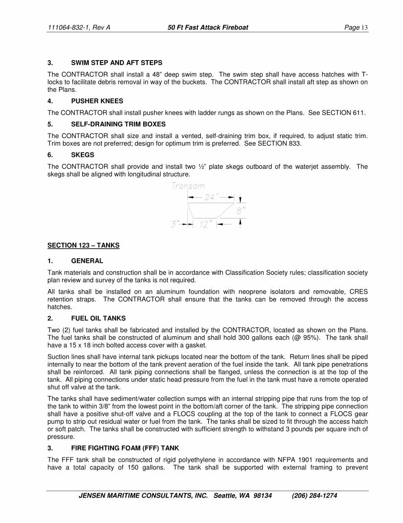
6. SKEGS
The CONTRACTOR shall provide and install two ½” plate skegs outboard of the waterjet assembly. The skegs shall be aligned with longitudinal structure.
SECTION 123 – TANKS
1. GENERAL
Tank materials and construction shall be in accordance with Classification Society rules; classification society plan review and survey of the tanks is not required.
All tanks shall be installed on an aluminum foundation with neoprene isolators and removable, CRES retention straps. The CONTRACTOR shall ensure that the tanks can be removed through the access hatches.
2. FUEL OIL TANKS
Two (2) fuel tanks shall be fabricated and installed by the CONTRACTOR, located as shown on the Plans. The fuel tanks shall be constructed of aluminum and shall hold 300 gallons each (@ 95%). The tank shall have a 15 x 18 inch bolted access cover with a gasket.
Suction lines shall have internal tank pickups located near the bottom of the tank. Return lines shall be piped internally to near the bottom of the tank prevent aeration of the fuel inside the tank. All tank pipe penetrations shall be reinforced. All tank piping connections shall be flanged, unless the connection is at the top of the tank. All piping connections under static head pressure from the fuel in the tank must have a remote operated shut off valve at the tank.
The tanks shall have sediment/water collection sumps with an internal stripping pipe that runs from the top of the tank to within 3/8” from the lowest point in the bottom/aft corner of the tank. The stripping pipe connection shall have a positive shut-off valve and a FLOCS coupling at the top of the tank to connect a FLOCS gear pump to strip out residual water or fuel from the tank. The tanks shall be sized to fit through the access hatch or soft patch. The tanks shall be constructed with sufficient strength to withstand 3 pounds per square inch of pressure.
3. FIRE FIGHTING FOAM (FFF) TANK
The FFF tank shall be constructed of rigid polyethylene in accordance with NFPA 1901 requirements and have a total capacity of 150 gallons. The tank shall be supported with external framing to prevent

111064-832-1, Rev A 50 Ft Fast Attack Fireboat Page 14
JENSEN MARITIME CONSULTANTS, INC. Seattle, WA 98134 (206) 284-1274
deformation. The tank shall have a 12 inch diameter bolted access cover with a gasket. Access cover shall be accessible when the tank is mounted in the vessel. The tanks shall be sized to fit through the access hatch and/or soft patch.
4. FRESH WATER TANK
One fresh water tank suitable for drinking water, 5 gallon capacity, with a spigot and fill shall be provided by the CONTRACTOR. The tank shall have a means to rapidly and securely install it on the shelf above the sink.
5. WASTE HOLDING TANK
Not required.
SECTION 150 – DECKHOUSE & DECK ENCLOSURES
1. GENERAL
The deckhouse shall be aluminum. All plating shall be aluminum alloy 5086-H116, 5083-H321 and/or 5083-H116 and extruded shapes shall be alloy 6061-T6 except as noted.
The arrangement of the deckhouse and deck enclosures, and the camber of the Pilothouse top is as shown on the Plans.
The ends of vertical deckhouse stiffeners shall be aligned with hull and/or deck framing or sole plates shall be used. Stiffener sole plates, as permitted in this Specification, shall extend a minimum of 1 inch past the periphery of the stiffener.
2. PILOTHOUSE
The Pilothouse brow shall extend forward of the windshield to act as a visor and shall extend aft of the cabin bulkhead as shown on the Plans. The Pilothouse top shall have a 1” coaming and drainage shall be provided through the vertical grab rails (SECTION 612) on the aft corners of the house.
The Pilothouse top shall provide foundations for sirens, a public address system, navigation lights, communications antennas, a spotlight, floodlights, emergency response lights, the FLIR and one fire monitor.
3. DECK ENCLOSURES
The CONTRACTOR shall construct deck lockers as shown on the Plans. All enclosures shall be weathertight when the hatches are latched in the closed position. The aft outboard corner of the aft deck lockers shall be reinforced to support the cleats and davit sockets.
See SECTION 167 for a description of the hatches.
SECTION 163 – SEA CHESTS
Sea chests shall be provided as required to serve the raw water systems on board. Sea chests shall be designed to have the same watertight integrity as the surrounding hull structure. Full penetration welds shall be provided for butts and seams of the sea chests and at the connection between the bottom shell plate and the sea chest.
Sea chests shall be provided as a minimum in the following locations:
Fire Fighting System:
Two (2) located in the engine room. Flanges in the relief and bypass returns to the sea chest shall be at least 12" above the design waterline as determined from the CWE. The sea chest will be fabricated as part of the hull structure, and shall include a removable strainer grate at the hull, with open area at least three times the area of the suction piping of the fire pumps. The strainer grate shall be removable from inside the vessel. Final configuration of the sea chest shall be approved by the OWNER. In addition, a clean out access inspection port shall be installed in the top of the sea chest above the static waterline.

111064-832-1, Rev A 50 Ft Fast Attack Fireboat Page 15
JENSEN MARITIME CONSULTANTS, INC. Seattle, WA 98134 (206) 284-1274
The fire pump inlet valves at the sea chest shall be electrically actuated DC CRES valve with manual back-up at the valves. Exact make and model DC valve requires OWNER’s pre-approval.
The sea chest shall be vented to remove trapped air at the top of the water column. The vent line shall be installed with a ball valve. The valve shall be accessible from the weather deck through one of the deck hatches.
Materials shall comply with piping schedule provided in SECTION 521.
Propulsion Equipment Raw Water Cooling System:
Two (2) each, one for each main engine, located in the engine room. Each raw water suction inlet shall be fitted with an aluminum strainer and a ¼-turn, lockable, CRES seacock valve sized according to the flow requirements of SECTION 256, and shall be designed and installed in accordance with the recommendations from the bodies listed in SECTION 008. The suction inlet shall be designed and located to allow the vessel to operate at maximum speed, forward or reverse, and still maintain required flow of raw water to the cooling system. A provision for clearing the intake in cases where they may become plugged up shall be included in the design. Access to clear the intakes shall be accessible from above the static waterline.
SECTION 167 – DOORS, HATCHES, MANHOLES AND WINDOWS
1. GENERAL
The CONTRACTOR shall be responsible for constructing the vessel such that the closures installed on the Vessel have the same structural strength and watertight (WT) integrity as the surrounding structure. All watertight doors and hatches shall be quick acting and shall be operable from both sides. Only high quality closures will be accepted. Full penetration welds shall be provided at the connection between the deck and the hull structural closures.
Locations of doors, hatches, manholes, bolted accesses, windows, portlights, and ventilation terminal weather closures are shown on the Plans except as noted otherwise. The CONTRACTOR shall confirm all sizes indicated in the Specifications with the sizes determined during detail design before purchase or fabrication. Where discrepancies exist between the Specifications and Plans, the CONTRACTOR shall consult with the OWNER’S REPRESENTATIVE to determine the appropriate size.
When determining clearances, the CONTRACTOR shall design to accommodate fire fighters wearing the full outfit of protective clothing, breathing devices and portable equipment.
Keying arrangement of doors, engines and engine starting shall be subject to approval by OWNER. All windows and hatches into the Pilothouse shall be capable of being secured from inside. All hatches opening to weather shall have recessed fittings to accept padlocks for securing all spaces.
Pre-treatment and finish for doors and frames shall be in accordance with the finish specifications in SECTION 631. All doors shall have bumpers. All doors and hatches shall have automatic hooks or locking mechanisms to retain hinged doors and hatches in the fully opened position. All doors and hatches shall be clear of opening mechanisms or other obstructions when open. Watersheds shall be fitted over all doors and windows opening to weather. Backing plates to prevent failures due to boat motions shall be provided for hinges, door closures, and latching devices.
2. DOORS
Main Deck - Deckhouse Entry (1)
30" x 72" clear opening, sill flush w/interior deck, aluminum weathertight doors, aluminum frame, 1 dog, neoprene gasket, Freeman Marine Series 1120 Heavy Duty Weathertight Door, Trioving 5382 or equal lock, 24"w x 30”h (minimum) x 1/4"t tempered glass window with UV tint. A positive latching device shall be provided that holds the doors completely open. The latching device shall be capable of maintaining the doors open while underway.
111064-832-1, Rev A 50 Ft Fast Attack Fireboat Page 16
JENSEN MARITIME CONSULTANTS, INC. Seattle, WA 98134 (206) 284-1274
Lower Cabin – Head Door (1)
26" x 72" clear opening, flush sill, aluminum honeycomb hinged door with louver. The door swing shall be as shown on the Plans. Positive latching devices shall be provided (a) to hold the door open and (b) to latch the door closed from the inside.
3. HATCHES
All hatches shall be fitted with gutter drains that shall be located on the aft end of the hatch and plumbed to drain overboard; check valves are not required.
All hatches shall have strength that is similar to surrounding deck structure. All hatches shall be fully insulated with sound and thermal insulation equivalent to surrounding structure. All hatch hardware shall be CRES.
Main Deck – Aft Water Jet Removal (2)
Clear opening to suit waterjet removal, bolt-in, watertight, soft patch, 6" radius corners, neoprene gasket, cover set flush with main deck, stainless steel hardware. Soft patches may be deleted if the jets can be removed though the drive room hatch.
Main Deck – Drive Room Access (1)
36" x 72" clear opening, flush, knife-edge seal, quick acting, watertight, aluminum hinged cover with Trioving or equal locks to secure the hatch in the closed position, weld-in, aluminum ring, 6” radius corners, neoprene gasket, Freeman Marine Series 3400 or equal, CRES hardware. The hatches shall hinge forward with two yoke-type hinges. Two CRES gas shocks shall be installed on each hatch to provide for a maximum of 50 pounds of force to open the hatch completely. The hatches shall be provided with a hold-open mechanism.
Main Deck - Seat Locker Access P/S (2)
Clear openings as shown on the Plans, aluminum weathertight hinged cover w/ neoprene gasket and recessed, CRES, anti-rattle fasteners with padlock eyes, to secure the hatch in the closed position. The locker is intended for hose storage, therefore, CONTRACTOR shall install 1” pipe chaffing bars around all sides of locker opening except in way of hinges. Hatch shall open for hands free access.
Main Deck - Main Engine Removal (2)
Clear opening to suit engine/pump/gear removal, minimum size as shown on PLANS, flush, knife-edge seal, quick acting, watertight, aluminum hinged cover with Trioving or equal locks to secure the hatch in the closed position, weld-in, aluminum ring, 6” radius corners, neoprene gasket, Freeman Marine Series 3400 or equal, CRES hardware. The hatches shall hinge outboard with two yoke-type hinges. Two CRES gas shocks shall be installed on each hatch to provide for a maximum of 50 pounds of force to open the hatch completely. The hatches shall be provided with a hold-open mechanism.
Deckhouse Top – Deck Locker Access (2)
Clear opening as shown on the Plans, aluminum weathertight hinged cover w/ neoprene gasket and recessed, CRES, anti-rattle fasteners with padlock eyes, to secure the hatch in the closed position. The locker is intended for hose storage, therefore, CONTRACTOR shall install 1” pipe chaffing bars around all sides of locker opening except in way of hinges. Hatch shall open for hands free access and rest on stops mounted on the lower cabin top.
Main Deck – Forepeak/Anchor Locker Access (1)
24" x 24" clear opening, flush, knife-edge seal, watertight, aluminum hinged cover, aluminum ring, neoprene gasket, Freeman Marine Series 2400 or equal.
4. WINDOWS
Pilothouse Front (3)
Aluminum weld-in frame, clear opening as shown on Plans, 3" radius corners, 3/8" tempered glass, Freeman Medium Duty or equal, electrically heated for deicing. The center window shall open outward and have a heavy duty hold open system for ventilation.
111064-832-1, Rev A 50 Ft Fast Attack Fireboat Page 17
JENSEN MARITIME CONSULTANTS, INC. Seattle, WA 98134 (206) 284-1274
Pilothouse Top, Fixed Type (5)
Aluminum weld-in frame, clear opening as shown on Plans, 3" radius corners, 3/8” tempered glass with UV tint, Freeman Medium Duty or equal.
Pilothouse Side, Horizontal Half-Sliding Type (2)
Aluminum weld-in frame, clear opening as shown on Plans, 3" radius corners, 1/4" tempered glass with UV tint, Freeman Medium Duty or equal.
Pilothouse Side, Fixed Type (4)
Aluminum weld-in frame, clear opening as shown on Plans, 3" radius corners, 1/4" tempered glass with UV tint, Freeman Medium Duty or equal.
Pilothouse Back, Vertical Half-Sliding Type (1)
Aluminum weld-in frame, clear opening as shown on Plans, 3" radius corners, 1/4" tempered glass with UV tint, Freeman Medium Duty or equal.
Pilothouse Back, Fixed Type (1)
Aluminum weld-in frame, clear opening as shown on Plans, 3" radius corners, 1/4" tempered glass with UV tint, Freeman Medium Duty or equal, electrically heated for deicing.
Pilothouse Front - Window Wipers (3)
Wynn Type 1850 pantograph style wipers or equal, 12VDC with variable speed operation, de-icing heaters in arms, self-parking and a washer system with a 2 gallon reservoir.
The wiper blades shall provide a linear sweep across the windows clearing as much area as possible and at least 60%. Wiper and washer controls shall be located inside the Pilothouse.
SECTION 170 – MAST
The CONTRACTOR shall design, construct and install a watertight mast/arch as shown on the Plans. The mast shall provide foundations for navigation lights, radar antenna, navigation antennas, fire service / public safety lights, shore power indicator light, halyard for flag and floodlights. Equipment, fittings and wireways shall be accessible for maintenance and equipment upgrade.
The mast shall be designed and constructed to withstand the design loads of SECTION 001 of this Specification with all of the equipment mounted on the mast.
SECTION 178 – DAVIT
The CONTRACTOR shall design, construct and install a portable davit with a manual winch with a 500 lb lifting capacity. The davit shall be mounted in either of the aft corners of the deck as shown on the Plans. When not in use, the davit shall be stowed in a bracket in the Drive Room.
SECTION 180 – FOUNDATIONS
The CONTRACTOR shall design, construct and install foundations for all equipment and machinery installed in the vessel. All foundations shall be constructed so as to minimize weight.
Foundations and supports for equipment and components with moving or rotating parts shall incorporate vibration isolation devices that will function under service environment and design loads conditions defined in SECTION 001.
All foundations shall be constructed so that positive and accurate alignment of equipment and components can be maintained. The rigidity of foundations and supporting structure shall be sufficient to prevent misalignment that would interfere with operation of the machinery and equipment and to preclude excessive

111064-832-1, Rev A 50 Ft Fast Attack Fireboat Page 18
JENSEN MARITIME CONSULTANTS, INC. Seattle, WA 98134 (206) 284-1274
vibratory motion or rocking on the foundation. Structural members of the hull shall be used as parts of the foundations. Foundations shall be constructed of the same material as the surrounding structure.
All equipment exposed to weather shall be fastened to its foundation with stainless steel studs, bolts, nuts, and washers. Installations requiring fasteners not made of stainless steel shall be submitted to the OWNER for approval.
SECTION 191 – FIXED BALLAST
No fixed ballast is anticipated for this Vessel.

111064-832-1, Rev A 50 Ft Fast Attack Fireboat Page 19
JENSEN MARITIME CONSULTANTS, INC. Seattle, WA 98134 (206) 284-1274
GROUP 200 - MAIN PROPULSION
SECTION 201 – GENERAL INFORMATION
See SECTION 012 for OWNER furnished equipment.
The CONTRACTOR shall develop the detailed design, provide and make fully operational a system which includes two main engines which power two water jets through marine gears off the flywheel ends of the engines and two fire pumps through clutches off the fronts of the engines. The CONTRACTOR, with assistance from main engine, water jet drive, and fire pump manufacturers, shall perform an analysis of the power distribution between the water jet and fire pump. The system shall be designed to maximize performance of the water jets and fire pumps. The design and installation shall include full control, alarm and monitoring and shall include a complete system.
The propulsion system shall be designed and installed in accordance with Original Equipment Manufacturer (OEM) recommendations and guidance. The Contractor shall obtain and provide certification letters from the OEM, verifying that the particular equipment installed on this vessel is in compliance with all OEM requirements.
SECTION 233 – MAIN ENGINES
The CONTRACTOR shall provide and install the main engines:
• Two (2) MTU (Detroit Diesel) 8V2000 M84 series, Tier II electronically controlled, turbocharged and aftercooled marine diesel engines, same rotation, rated at 1085 brake horsepower at 2450 rpm, intermittent duty rating.
The engines will be heat exchanger cooled, 24VDC electric starting. The engines and reduction gears shall be provided with U.S.C.G. approved flexible hose connections for all cooling water, fuel oil, and lubricating oil piping connections. In addition to standard engine equipment, the following optional equipment shall be provided for each engine:
• Alternator Mounting Point - 24VDC/120VAC/240VAC generator/inverter/charger • Resilient engine mounts per manufacturer recommendations • Engine mounted fuel supply pump, relief valve, manual priming or with separate manual priming pump • Primary fuel filter, Racor duplex with restriction gage and isolation valves, USCG approved • Secondary engine mounted fuel duplex filters • Engine integrated fuel cooler • Crankcase air filtration system, Racor CCV8000 or equal • Marine Air filter/silencer system, Racor AF M601212 or equal • Lube oil filters, dual remote mount located inboard of engine • Lubricating oil drain lines; inboard located dipstick; oil fills. • 110V/120V AC jacket water heater, Kim Hotstart or equal, with individual breakers at the main panel
(The engine jacket water heater shall be sized to heat engines to a minimum of 90 deg F in conditions defined in SECTION 001.)
• SAE #1 flywheel & housing • Waste heat accessory valve, CRES • Water cooled stainless steel water exhaust injection elbow • Monitoring displays with sensor systems (see SECTION 252) • Front crank PTO flange rated for full power delivery to the fire pump (see SECTION 521) • Emergency shut down fuel or combustion air valves at the engine, remotely operated at pilothouse,
manual reset. • Heat exchanger, attached • Raw water pump, attached • Coolant expansion tank, attached, with pressure cap and low level alarm

111064-832-1, Rev A 50 Ft Fast Attack Fireboat Page 20
JENSEN MARITIME CONSULTANTS, INC. Seattle, WA 98134 (206) 284-1274
The main engine purchase technical specification shall be approved by the OWNER or OWNER'S REPRESENTATIVE. The OWNER shall be notified when the purchase order is provided to the supplier.
A Torsional Analysis Report shall be provided by the engine manufacturer to determine a suitable torsional coupling to be installed by the CONTRACTOR between the main engine and the main reduction gear and between the main engine and the fire fighting pump.
The CONTRACTOR shall provide the torsional vibration analysis and whirling calculation of the complete propulsion assemblies shall be conducted during the design phase of the vessel. The CONTRACTOR shall supply one copy of the torsional vibration analysis report to the OWNER.
The CONTRACTOR shall provide and install marine grade vibration isolators, Christie & Grey or equal. The vibration mount supplier shall perform a six degree-of-freedom (6DOF) study to determine suitable isolators.
The main engines and main reduction gears shall be fitted on heavy engine beds and installed to the satisfaction of the OWNER in accordance with the manufacturer's recommendations. The CONTRACTOR shall submit an alignment procedure to the OWNER or OWNER'S REPRESENTATIVE for approval. After completion of construction, the shafting system shall be aligned with the vessel in the water. The final alignment shall be witnessed by the OWNER or OWNER'S REPRESENTATIVE. All readings shall be recorded. A shaft alignment report shall be provided to the OWNER for approval. Collision chocks shall be installed.
OPTIONAL ITEM: The CONTRACTOR shall provide a separate price to substitute the following:
• Two (2) Caterpillar C18 ACERT, Tier II electronically controlled, turbocharged and aftercooled marine diesel engines, same rotation, rated at ~1100 brake horsepower at 2300 rpm, high performance ("E") rating, if Caterpillar offers the engine with a Tier II Commercial rating.
OPTIONAL ITEM: The CONTRACTOR shall provide a separate price to extend the warranty of the propulsion engines to 5 years or 3000 hours. [See Appendix B.]
SECTION 241 – REDUCTION GEARS
Two (2) Marine reduction gears, ZF 665 TS or equal, matched to the rotation of the main engines, with one (1) reverse gear and two (2) forward gears and neutral gear shall be provided and installed by the CONTRACTOR. Reverse gear is intended only for clearing the waterjet inlet screen.
The reduction gears shall be rated to match the full input power and duty cycle of the main engines and shall have reduction gear ratios optimized to the requirements of both the fire pump and water jet drive in low gear and the jet drive in high gear. The reduction gear output shall not be of the controllable slippage type.
The reduction gears shall readily interface with and be operated by the engine control system. The reduction gears shall use the same lubrication oil as the main engines and shall be heat exchanger cooled. The reduction gear supplier shall include mounting brackets, cooling lines, oil drain lines, and propulsion shaft flanges.
In addition to standard equipment, the following equipment shall be provided for each reduction gear:
• Hydraulic clutchable PTO (SAE “C”, 4-bolt) • Sensor systems (see SECTION 252)
The reduction gear purchase technical specification shall be approved by the OWNER or OWNER'S REPRESENTATIVE.
Alignment and foundation requirements shall be the same as for the main engine. See SECTION 233.
SECTION 243 – PROPULSION SHAFT SYSTEM
The CONTRACTOR shall provide and install a complete propulsion shaft system to transmit power from the gearbox to the water jet drive. Propulsion shafting shall include a shaft with a CV (constant velocity) joint to

111064-832-1, Rev A 50 Ft Fast Attack Fireboat Page 21
JENSEN MARITIME CONSULTANTS, INC. Seattle, WA 98134 (206) 284-1274
allow for an offset between the output flange of the main reduction gear and the water jet drive. The propulsion shaft system shall be designed in accordance with the requirements of one of the following:
1.) ABS Rules for Building and Classing Steel Vessels for Service on Rivers and Intracoastal Waterways
2.) ABS Rules for Building and Classing High Speed Craft
3.) ABYC P-6
The CONTRACTOR shall provide and install two (2) bulkhead seals at the aft engine room bulkhead, one per shaft, to prevent progressive flooding from the water jet drive room into the engine room. The seals shall be designed and installed so that they can be replaced without removing the shaft from the boat.
CONTRACTOR shall provide a certificate verifying that the propulsion shaft system is designed and installed in compliance with the requirements set forth in this section.
Alignment requirements shall be the same as for the main engine. See SECTION 233.
Additionally, the CONTRACTOR shall install shaft guards over any moveable parts of the propulsion shaft system that could cause harm while in operation. Shaft guards shall be easily removable for inspection and maintenance.
SECTION 245 – RESISTANCE & PROPULSION CALCULATIONS
The CONTRACTOR shall provide resistance and propulsion calculations based on the hull form, predicted weight and center in the design condition (SECTION 833), and installed power and provide the prediction to the OWNER.
SECTION 246 – WATER JET PROPULSORS
The CONTRACTOR shall provide and install two (2) water jet drives with impellers sized in accordance with manufacturer’s recommendations and OWNER approval. The water jet drives shall be fitted with remote operated thrust reversing buckets integral to the design and shall be operated from the pilothouse.
The water jet drives shall be:
• Two (2) Rolls Royce FF450S water jets, with hydraulically actuated steering nozzles and reversing buckets
The water jet drive impeller shall not cavitate so as to over-speed or damage the impeller in any operational condition, except voluntary operator RPM limits to preclude cavitation shall be allowable in towing condition. If engine RPM must be voluntarily limited by the operator to control cavitation in towing conditions, limits shall be posted to be visible at the helm station(s).
The water jet drives shall be provided with an integral hydraulic steering and reverse bucket systems that will interface with the steering controls described in SECTION 561 and the interceptors described in SECTION 114. Alarms shall be reported at the pilot’s station and on deck. Bucket position indicator shall be provided at the main steering station.
The CONTRACTOR shall provide all manufacturer recommended water jet spares for the first two years of operation.
OPTIONAL ITEM: The CONTRACTOR shall provide a separate price to substitute the following:
Two (2) Hamilton Jet HJ403 water jets, with hydraulically actuated steering nozzles and reversing buckets.
OPTIONAL ITEM: The CONTRACTOR shall provide a separate price to include all additional manufacturer recommended spares for years 3 through 5 of operations.

111064-832-1, Rev A 50 Ft Fast Attack Fireboat Page 22
JENSEN MARITIME CONSULTANTS, INC. Seattle, WA 98134 (206) 284-1274
SECTION 251 – MACHINERY VENTILATION AIR
Air intakes shall be fitted to minimize the possibility of ingestion of water into the engine compartments. The baffles shall be equipped in the intakes to allow possible water intrusion to drain onto the deck. The intakes shall have means for closing to prevent air from entering the machinery space in case of a fire within. (See SECTION 555.) Controls for closure of the intakes shall be by electric solenoid with controls outside the machinery space; reset may be manual.
1. COMBUSTION AIR
Combustion air for the main engines shall be drawn from the engine room. The engine room air intakes shall be sized in accordance with main engine demand requirements, manufacturer’s recommendations and shall be sized to provide a maximum air velocity of 3000 feet per minute unless otherwise approved by the OWNER. Louvers and baffles shall be provided to minimize the intake of spray and shall drain to deck. The locations shall be as shown on the General Arrangements. The air intakes shall be ducted to the bottom of the engine room.
2. COOLING AIR
Cooling air for the machinery space shall be provided, for when the main engines are not running. Powered ventilation fans shall be thermostatically controlled. The ventilation system shall comply with ABYC H-32 and NFPS 302. (See SECTION 512.)
SECTION 252 – CONTROLS, INDICATORS AND ALARMS
1. PROPULSION CONTROLS
The CONTRACTOR shall provide a propulsion control and monitoring system with electronic back up, operable from the pilothouse console, and has provisions for starting, stopping and controlling each engine.
Manually operated main engine emergency shut downs shall be operated remotely from the pilothouse. The actuator for the port engine shall be placed to the port side of the corresponding actuator for the starboard engine. Automatic shut down systems shall not be permitted. The manual release fire suppression system (see SECTION 555) shall be interfaced with the engine control system to ensure a safe shut down of the main engines in case of a fire in the machinery space.
The CONTRACTOR shall provide and install a twin jet, dual station propulsion control system w/a roving remote station, Rolls-Royce Vector Stick II or equal. The system shall include engine throttle controls, reduction gear shift and engagement controls with neutral safety lockout for starting the main engines.
The throttle and gear controls shall be separate. At the primary station, the CONTRACTOR shall provide a steering wheel, throttle controls w/clutch controls and a joy stick vectoring system that controls water jet steering and reversing, engine speed and the bow thruster. Control lever cant angle will be determined during console mock-up. (See SECTION 420.) At the remote station, the system shall include the joy stick vectoring system. Control heads shall be located at both the Pilothouse helm station and at the portable remote control station for low speed maneuvering.
In addition to standard engine equipment, the following controls shall be provided for each engine:
• MTU electronic engine controls cabled into Marine Junction Box • MTU interface module with diagnostic connection, ignition, stop engine and check engine lamps • Ignition switch (see SECTION 320) • NEMA 4 engine start and stop buttons for pilothouse • NEMA 4 emergency stop buttons for pilothouse control station • Engine Synchronization Mode • Low Idle/Slow Vessel Mode • Fire Research Pro-S Governor
All controls shall be installed in strict conformity with manufacturer’s instructions. The remote shall be supplied with 32’ of cable and shall plug into a port on the starboard side of the aft pilothouse bulkhead.

111064-832-1, Rev A 50 Ft Fast Attack Fireboat Page 23
JENSEN MARITIME CONSULTANTS, INC. Seattle, WA 98134 (206) 284-1274
OPTIONAL ITEM: The CONTRACTOR shall provide a separate price to substitute the following:
Hamilton Control System with Maneuvering Joystick Control (MJC) with Hand-held Remote Control (HHR).
2. PROPULSION INDICATORS AND ALARMS
The CONTRACTOR shall provide and install an MTU SmartLine Engine Control System display. The display shall provide monitoring, alarm, and diagnostic information for the two main propulsion engines. One display shall be provided for each engine. The following engine information shall available through the SmartLine display:
• Engine speed • Percent load • Engine hours • Turbo boost pressure • Coolant temperature • Oil pressure • Oil temperature • Fuel flow rate • Fuel pressure • Fuel temperature • Inlet manifold temperature • Reduction gear oil pressure • Reduction gear oil temperature • Battery voltage
Tank levels shall be reported through the SmartLine display.
Unless individually provided through the MTU SmartLine display, the CONTRACTOR shall install each of the following audible and visual alarms near the vessel operator’s position:
• Main engine coolant high temperature • Main engine coolant low level • Main engine raw water low flow • Main engine low oil pressure • Main reduction gear low oil pressure • Main reduction gear high oil temperature • Main engine high exhaust temperature • Water jet high temperature • Water jet low oil pressure • Generator/Inverter/Charger failure
The CONTRACTOR shall provide and install warning lights and audible alarms for each engine/propulsor set inside and audible alarms on the aft deck. The warning light and audible alarm shall activate simultaneously when a sensor detects an abnormal reading. The warning light shall not extinguish until the propulsion system has returned to normal.
The CONTRACTOR shall provide and install a “dead” engine indicator light and summary alarm buzzer with silencer for each main engine.
OPTIONAL ITEM: The CONTRACTOR shall provide a separate price to substitute a Caterpillar Marine Power Display (MPD) if the Caterpillar engine is available.
3. OTHER CONTROLS, INDICATORS AND ALARMS
See SECTION 246 - Water Jet Propulsors, SECTION 331 – Receptacles and Shore Power, SECTION 436 – Alarm Systems, and SECTION 506 – Fills, Vents and Soundings.

111064-832-1, Rev A 50 Ft Fast Attack Fireboat Page 24
JENSEN MARITIME CONSULTANTS, INC. Seattle, WA 98134 (206) 284-1274
SECTION 256 – ENGINE AND REDUCTION GEAR COOLING SYSTEMS
1. GENERAL
All cooling systems shall be sized and installed in accordance with equipment manufacturer recommendations. The systems shall maintain engine temperatures within the engine manufacturer's recommended range under all operational and ambient conditions as described in SECTION 001. Main engines’ and main reduction gears’ oil and coolant waters shall be cooled through engine and gear mounted heat exchangers. The cooling system shall have vents and drains to facilitate winterizing the system without disassembling piping or hose joints.
2. RAW WATER
The raw water supply for the heat exchangers shall be provided from engine driven pumps. Raw water shall be discharged through the wet exhaust systems.
Each engine’s heat exchangers shall be fed with raw water from separate sea suctions (see SECTION 163). The raw water supply shall be strained through duplex-type strainers with baskets fabricated from 70/30 copper nickel material. The strainers shall have the provision to clean one basket, while operating the engine on the adjacent. Strainer housings shall be clear to allow for visual inspection of the baskets. Access to the basket shall be via top mounted lids with quick release fasteners and retaining mechanisms shall prevent loss of lids or fasteners.
Raw water systems shall have vent valves and drain valves so that the system can be completely drained, flushed and completely winterized without disassembling piping system joints. The vent valves shall allow trapped air to be removed from the raw water before it reaches the raw water pumps.
All hoses shall be heavy duty with 2 stainless steel clamps, non-spring loaded type, at each end. Hoses shall not be used above 4” NPS.
All piping and hoses shall be neatly run and secured. Dissimilar metals shall be galvanically isolated.
Discharge shall be via the wet exhaust system for each engine.
3. COOLANT WATER
Main engine and main reduction gear coolant water shall be routed through closed loop water circuits with provisions for coolant expansion and pressure relief sized to the engine manufacturer’s recommended practices. The coolant water shall consist of a mixture of distilled water and coolant type approved by the engine manufacturer.
4. PIPING SCHEDULE
Size: 2 1/2" and over 2" and under Pipe: Schedule 40 / STD galvanized Steel
pipe, ASTM A53
Schedule 40 or STD 6061 or 6063 Aluminum pipe ASTM B241
Schedule 40 or STD CuNi 90/10 ASTM B466
Schedule 40 or STD 316L Stainless Steel ASTM A312
Schedule 40 / STD galvanized Steel pipe, ASTM A53
Schedule 40 or STD 6061 or 6063 Aluminum pipe ASTM B241
Schedule 40 or STD CuNi 90/10 ASTM B466
Schedule 40 or STD 316L Stainless Steel ASTM A312
Hose: Cooling water hose, SAE J2006 Trident Marine or equal up to 4” NPS
Cooling water hose, SAE J2006 Trident Marine or equal
Takedown Joints: Pipe: 150# ANSI B16.5 flanges Hose: Two (2) worm gear hose clamps, min. 1/2” wide, CRES 316, ASTM A-312
Pipe: 150# ANSI B16.5 flanges Hose: Two (2) worm gear hose clamps, min. 1/2” wide, CRES 316, ASTM A-312
Valve Body: Bronze Bronze Valve Mountings: N/A N/A
111064-832-1, Rev A 50 Ft Fast Attack Fireboat Page 25
JENSEN MARITIME CONSULTANTS, INC. Seattle, WA 98134 (206) 284-1274
Fittings: Hose: CRES 316L, barbed fittings Pipe: CRES 316L flanged ANSI B16.5
Hose: CRES 316L, barbed fittings Pipe: CRES 316L socket weld ANSI B16.11
SECTION 259 – ENGINE EXHAUST SYSTEMS
The CONTRACTOR shall provide and install a wet exhaust system with a water lift muffler for each of the propulsion engines installed in the vessel. Exhaust systems shall be installed in accordance with manufacturer’s recommendations.
A test gage connection shall be provided in each exhaust system near the engines to be used for taking exhaust back pressure measurements as per OEM requirements.
The exhaust system shall prevent the engines from being back-flooded in situations including, but not limited to, any design trim or heel angle, from running the vessel in reverse, and from wave action hitting the vessel’s exhaust port such as would occur from a sudden stop of forward movement. The exhaust system design shall prevent the back-flooding from occurring whether running one engine or both.
Raw water from the engine cooling system heat exchanger shall be injected into the exhaust stream near the outlet of the turbo chargers to cool the exhaust system. See SECTION 256. Each exhaust system shall be installed with a removable raw water injection ring to facilitate replacement. A temperature sensor shall be installed at the spray ring for early warning of cooling water low flow.
Dry sections of the exhaust system (upstream of raw water injection point) shall be 321 or 347 stainless steel for exhaust temperatures over 750° F. Standard exhaust fittings, which fully satisfy the engine manufacturer's requirements and which are fabricated from other stainless steel grades may be used with the specific written approval of the OWNER.
Uncooled (dry) sections of the exhaust systems shall be insulated. Insulation shall be 4" thick calcium silicate covered with glass cloth. Each exhaust system shall be equipped with a stainless steel flexible section for vibration resistance and thermal expansion. 4" thick glasscloth blankets shall be used at flex joints. All insulation shall have an impervious outer layer so as to minimize the absorption of oil mist. Aluminum sheeting shall be used to protect insulation in high traffic areas or where the risk of damage is high.
Cooled sections of the exhaust system (downstream of the water injection point) shall be 316L stainless steel, 5086, 5456 or 6061 aluminum, and/or short sections of marine exhaust hose. Hose connections shall be slip on and each connection shall be secured by two (2) stainless steel worm gear hose clamps.
SECTION 261 – FUEL OIL SYSTEM
1. GENERAL
The CONTRACTOR shall provide and install a fuel system in accordance with the requirements of the engine manufacturers and ABYC Project H-33, Diesel Fuel Systems. The system shall provide for all necessary pipes, valves, hoses, fittings, and equipment for filling, venting, sounding, filtering, supplying, returning, and stripping of diesel fuel, and all other necessary functions.
2. FUEL OIL SERVICE SYSTEM
The fuel service system shall supply fuel to the propulsion engines and return excess fuel to the storage tanks. Fuel service system supply and return pipe and hose sizes shall be within the engine manufacturer's requirements. Piping and components shall be sized to provide for simultaneous operation of both of the main engines on either or both tanks with 10% spare capacity. Valves used in the fuel system shall have an indicator of the valve's position. The supply and return lines shall be fitted with 3-way valves to allow for tank selection for both the supply and return fuel. The 3-way valves shall not permit the return lines from being shut off in any position. Where flexible connections are required for fuel supply and return systems, reinforced hose with detachable reusable type fittings shall be used.
The fuel system shall be provided with remotely operated quick-acting valves or solenoid valves on the suction lines at the fuel tanks to activate a manual emergency shutoff for the fuel supply in case of a fire.

111064-832-1, Rev A 50 Ft Fast Attack Fireboat Page 26
JENSEN MARITIME CONSULTANTS, INC. Seattle, WA 98134 (206) 284-1274
They shall be operated remotely from the pilothouse. The remote operator for the port engine shall be placed to the port side of the corresponding actuator for the starboard engine in the pilothouse. Automatic fuel shut down systems shall not be permitted.
Fills, vents and soundings shall comply with the requirements of SECTION 506.
The fuel system shall be provided with a fuel flow meter and total fuel consumed indicator for each engine with an accuracy of within 3% of the reading. Fuel flow readings shall be in gallons per hour and total fuel consumed readings shall be in gallons. The flow meter shall be equipped with a fuel consumed reset switch adjacent to the gauge. Reset switches shall be protected to prevent accidental resetting of the fuel flow meters. The ECMS (Engine Control Monitoring System) may be used to provide the fuel monitoring capability.
3. FUEL OIL TANKS
See SECTION 123.
4. PIPING SCHEDULE
Type: All Hose: USCG Type A1 Fuel Hose,
46 CFR 56.60-25, SAE J1942 Takedown Joints: Threaded union, ground joint, CRES
316, ASTM A-312, 150# Valve Body: Ball valve, CRES 316, threaded ends,
ASTM A-312, 150# Valve Mountings: CRES, renewable disk and
regrindable seat Fittings: CRES 316, Parker Series 20 or equal,
ASTM A-312, SAE J1475, 150#
SECTION 262 – LUBE OIL SYSTEM
1. GENERAL
The main engines, main reduction gears, and fire pump gears shall all use the same manufacturer approved lubricating oil type.
The CONTRACTOR shall provide a fast lubricating oil change system (FLOCS), and permanent hose connections shall be installed on the main diesel engines, fire pump gears, and main reduction gears, to allow for convenient lubrication oil changes. These hoses shall be routed to a manifold with individual shut off valves, labeled for each oil connection.
A suction line shall be provided from the manifold to a fitting above deck on the side of the wheelhouse, recessed with a cap for easy hook up of hoses for oil changes. A label plate shall be provided at the deck connection with the words “LUBRICATION OIL SUCTION”. The suction line shall be fitted with a snap Aeroquip Hydraulic-type Quick Disconnect fitting.
Materials shall comply with piping schedule provided in SECTION 261.

111064-832-1, Rev A 50 Ft Fast Attack Fireboat Page 27
JENSEN MARITIME CONSULTANTS, INC. Seattle, WA 98134 (206) 284-1274
GROUP 300 - ELECTRICAL SYSTEMS
SECTION 301 – GENERAL INFORMATION
See SECTION 012 for OWNER furnished equipment.
The CONTRACTOR shall develop and submit for Owner approval an Electrical Load Analysis (ELA) for the system. The ELA shall be used for sizing of alternators, battery banks, battery chargers, power conversion equipment, circuit conductors, and associated equipment.
Prior to installation of equipment requiring electrical connections, the CONTRACTOR shall supply the OWNER with a copy of their shop drawings and an electrical component layout drawing that shall be approved by the OWNER. This shall include, at a minimum, an electrical schematic of the entire electrical system to include circuit designation, appliance description, circuit voltage, voltage type alternating current (AC) or direct current (DC), circuit length in feet, amperage draw, conductor size, and calculated voltage drop. At the OWNER's request, the CONTRACTOR shall provide additional electrical system information in the format requested. Prior to any wiring, the electrical schematic of the entire electrical system shall be pre-approved by the OWNER.
The boat electrical system shall be capable of supplying the boat's power requirements under all operational conditions and design conditions as specified in SECTION 001. The system shall be designed such that required electrical devises can be powered with both main engines running at idle. System back-up shall be such that there is sufficient electrical power developed to allow the vessel to return on a single engine.
The electrical system will include batteries and alternators to provide DC power and shore power and inverters to provide AC power.
All electrical installations shall be marine grade and shall comply with the recommended practices of the ABYC, AC & DC Electrical Systems on Boats, unless otherwise specified. Equipment and components shall be installed and tested in accordance with manufacturer's requirements and recommended practices so as not to void manufacturer's warranty provisions. All electrical systems and equipment shall operate within the manufacturer's parameters under the conditions specified in SECTION 001.
The vessel’s electrical system shall consist of an AC power distribution system from the 12VDC to 120VAC inverters, an exterior connection for shore power supply to the main panel, a 24VDC battery/alternator system and a 24VDC/12VDC power distribution system for engine starting and other boat services.
The vessel shall have five electrical power modes:
(1) Dockside (shore power & inverter/chargers) (2) Normal Running – propulsion engines running (generators/inverters & battery power) (3) Firefighting – propulsion engines and fire pumps running (generators/inverters & battery
power) (4) Diving Operations – engines not running (inverters & battery power) (5) Special Operations – propulsion engines idling (generators/inverters & battery power)
AC power consuming equipment shall operate within the manufacturer's parameters with a steady state voltage variation of plus or minus 5 percent, and with a frequency variation of plus or minus 3 percent. DC power consuming equipment shall operate within the manufacturer's parameters with a steady state voltage variation of plus or minus 10 percent or 3 percent in accordance with ABYC. Temporary voltage fluctuations during motor starting shall not cause damage or interruption of service to equipment.
Galvanic corrosion of electrical equipment, hardware, enclosures, housings and mountings shall be minimized by the following methods:
• To the extent possible, select materials not subject to galvanic corrosion. • Selection of materials in order to minimize galvanic corrosion between galvanically active dissimilar
materials. • Insulation of dissimilar metals with gaskets, washers, sleeves and bushings of materials such as
fiberglass or Micarta.
111064-832-1, Rev A 50 Ft Fast Attack Fireboat Page 28
JENSEN MARITIME CONSULTANTS, INC. Seattle, WA 98134 (206) 284-1274
• The isolation transformer shall provide galvanic protection on the shore power input, Charles 12KVA, or equal.
SECTION 302 – MOTORS AND CONTROLLERS
All motors and controls shall be selected as to size and type to suit their respective application and location.
The propulsion engine start and certain other electrical equipment shall be 24VDC power. All other controls and motors shall be DC where possible, and all shall be rated for marine service.
Unless otherwise specified, all other motors shall be designed for 12VDC, in accordance with ABYC and IEEE. All motor controls shall be in accordance with ABYC and IEEE regulations and clearly labeled as to their operations. Where controls are located out of sight of the motors, disconnect master switches shall be furnished.
Controls for the ship service auxiliaries shall have overload and low voltage protection. Controls for vital propulsion auxiliaries shall have overload protection and low voltage release.
Motor controls operating with float, vacuum, or pressure switches shall have provision for "hand" start and continuous operation in the event of failure of these switches.
The motors and controls installed in machinery spaces shall be designed for operation on an ambient temperature of 50 degrees Centigrade and elsewhere for 40 degrees Centigrade.
SECTION 303 – PROTECTIVE DEVICES
The CONTRACTOR shall provide over-current and short circuit protective devices for all electrical power distribution circuits. Circuit breakers shall be used in lieu of fuses for primary circuit protection. As a minimum, double-pole circuit breakers shall be used for the main AC shore power breaker and the main breaker provided at each 12 VDC or 120 VAC distribution panel. Circuit breakers shall be of the 18mm mini-breaker thermal magnetic type and shall be DIN rail mounted within the enclosure. Circuit breakers shall be UL approved and designed to withstand the marine environment.
Spare circuit breakers shall be provided for all AC and DC panels. A minimum 10% of installed ratings shall be provided including at least one 20 amp 115VAC, one 15 amp 24VDC, one 30 amp 24VDC, two 15 amp 12VDC and one 30 amp 12VDC. The CONTRACTOR shall provide lockout devices to physically disable power supply during maintenance operations for all AC and DC panels. Rectifiers, regulators, and control accessories shall be shielded from water entrance, with minimum interference to air flow.
An equipment leakage circuit interrupter shall be installed with or in addition to the main shore power disconnect circuit breaker(s) or at the additional over current protection as required by E 11.10.2.8.3 whichever is closer to the shore power connection (Equipment Leakage Circuit Interrupter diagram). This device shall meet the requirements of UL 1053 Standard for Safety Ground-Fault Sensing and Relaying Equipment and the requirements of UL 943 Ground-Fault Circuit-Interrupters with the exception of trip level and trip time. Trip level shall be a maximum of 30 milliamps. The trip time shall be a maximum of 100 milliseconds. This devise shall be installed on the primary side of the isolation transformer.
SECTION 304 – CABLES AND WIRING
1. GENERAL
Wiring leading to engine mounted and shock mounted electrical equipment shall have sufficient slack so motion of the equipment on its mountings does not stress the wire or wiring connections. Exposed wiring subject to mechanical damage shall be protected by removable covers. No cabling other than lighting shall be installed in way of engine access hatches. All cabling shall be thermally insulated when passing near a heat source.
Where cables pass through watertight bulkheads, watertight stuffing tubes or CSD plugs shall be installed; where cables pass through tight decks, kickpipes with stuffing tubes or CSD plugs shall be used. Care shall

111064-832-1, Rev A 50 Ft Fast Attack Fireboat Page 29
JENSEN MARITIME CONSULTANTS, INC. Seattle, WA 98134 (206) 284-1274
be taken that no sharp corners are present where cables are pulled through kickpipes, conduit, or pass-throughs.
The CONTRACTOR shall size all cables to provide a loop of excess cable behind all instruments, systems and displays to facilitate removal and full access to the back of the item without disconnection.
Main wireways for electrical distribution, instrument and alarm systems shall be laid out in advance of installation. Wherever penetration of tight or non-tight structure is required 10% spare capacity shall be installed, as a minimum one spare penetration.
All AC circuits shall be safety grounded through the panels or locally at receptacles. All DC power circuits shall be two-wire. The hull shall not be used as a current-carrying return.
The AC panel neutral shall be grounded to the transformer grounding point as per ABYC. The engine blocks shall be bonded to each other and the hull.
All electrical equipment shall be mounted on electrical insulating material and equipment with conductive enclosures, regardless of mounting method, shall have a separate conductor connected between the equipment enclosure and the boat's bonding system to ensure electrical grounding of the enclosure. The conductor shall be no less than one gauge size under that of the feeder cable as per ABYC.
All cables, cable terminals, and wiring used in the wiring of engine electrical components shall be in accordance with SAE Standard J378.
2. CABLES
Wire color-coding shall be in accordance with IEEE-45 or ABYC standards and identified by circuit number and be shown on the CONTRACTOR prepared WORKING DRAWINGS. Standard being used shall also be identified. See also SECTION 305.
A. DC Cable
All DC conductors #14AWG to #8AWG shall be type THHN unless otherwise noted. Battery cables shall be type SGT SAE J-1127 with polarity clearly and permanently marked. All 12VDC circuitry is 2-wire negative ground.
B. AC Cable
Single conductors shall be type THHN unless otherwise noted. Multiple conductor cables shall be type TTNI. Insulation colors shall be black for hot, white for neutral, and green for ground. Exposed cable subject to damage shall be type TTNIA aluminum armored.
3. CABLE HANGERS
AC and DC cabling shall be separated to avoid AC interference per ABYC recommendations.
Individual wires and harnessed wires shall be supported with clamps or straps, at least every 18 inches on horizontal runs and every 14 inches on vertical runs, attached to fixed structural members of the boat. Clamps or straps used for wire and cable support shall each be secured by two screws except that clamps supporting one cable number 10 AWG twin or smaller may be of the one screw type. Metal supports shall be designed to secure cable without damage to insulation and shall be at least 1/2 inch wide. Non-metallic clamps or straps shall not be used.
Cables installed in groups shall be supported in metal hangers and arranged, as far as is practicable, to allow air circulation to cool each cable. Cable hangers supporting groups of cables shall be spaced at intervals no greater than 18”. Cables shall be shall be run in spacious wire ways located for easy access. Cables shall not be stacked more than two deep, although cableways may be multi-tiered. Finished cableways shall have space for 20% spares for future additions. Cables shall be clamped with stainless steel straps to cableways and supports in machinery spaces and where no other support is provided.

111064-832-1, Rev A 50 Ft Fast Attack Fireboat Page 30
JENSEN MARITIME CONSULTANTS, INC. Seattle, WA 98134 (206) 284-1274
4. WIRE LUGS, TERMINALS, AND CONNECTORS
Metals used for the terminal studs, nuts, and washers shall be corrosion-resistant and galvanically compatible with the wire and terminal lugs. Equipment lugs for external cable connections shall be of the solderless type with ring type ends except as otherwise specified herein.
Cables or wiring leading to shock-mounted equipment shall be formed into a coil or loop to minimize the effect of movement or vibration.
Minimum terminal-stud sizes for various wire sizes shall be as follows:
Conductor Size Minimum Stud Diameter 16-22 AWG 0.125” (# 5) 12-14 AWG 0.164” (# 8) 6-10 AWG 0.190” (# 10) 2-4 AWG 0.250” (1/4”)
1/0-4/0 AWG 0.313” (5/16”) No more than four conductors shall be connected to any terminal stud. Where more than four conductors are to be connected, two or more terminal studs shall be connected together by means of jumpers. The holes in ring-type terminal lugs shall be of a size that will fit the terminal stud.
Wires terminating in panels, junction boxes or fixtures shall have a length of wire sufficient to relieve all tension, to allow for disconnection, and to permit multiple wires to be formed at terminal studs. Heat shrink type connectors shall be used.
Cable and wire connections shall be made within electrical equipment enclosures, junction boxes or connectors, as applicable. Where equipment is designed for external connection (example: starters), exposed energized terminals shall be protected against accidental shorting or accidental contact by personnel by the installation of insulating sleeves, removable terminal boots or an insulating barrier. Where connectors are used they shall be Weather Pack or Deustch.
Outside of electrical enclosures and where practical, NEMA 4X connection boxes with screw-type terminal boards shall be utilized for wiring connections. Cables shall be continuous between terminals. In-line splices shall only be used where the cable supplied with OEM equipment is not long enough to reach the termination point, and the installation of a connection box is not practical. Splices shall be made with heat shrink butt splice connectors, covered with heat shrink tubing as shown in Figure 304-1. Where an in-line splice would be authorized under this paragraph, a Deutsch DT Series GP connector may be used to facilitate maintenance, repair, and replacement of the OEM equipment.
Figure 304-1. Typical In-line Cable Splice
.

111064-832-1, Rev A 50 Ft Fast Attack Fireboat Page 31
JENSEN MARITIME CONSULTANTS, INC. Seattle, WA 98134 (206) 284-1274
Battery lugs shall be of commercial manufacture soldered to the conductor, or fabricated using sealed type compression lugs installed to the cable using a closed cycle compression tool. A heat shrink sleeve with internal sealant shall be fitted over the end of the cable insulation and the lug. Battery cables shall be supported within 36” of the battery terminal connection to relieve strain from the lugs and battery terminals.
4. WIRING DIAGRAMS
Wiring diagrams shall show all relays, solenoids, motors, switches, fuses, and junction boxes. “As Built” wiring diagrams also include the location of all relays, solenoids, motors, switches, fuses, and junction boxes. The wiring diagram shall be broken down into wiring zones, showing all tracer codes and color codes.
SECTION 305 – ELECTRICAL LABELS AND MARKINGS
The CONTRACTOR shall mark all switches, electrical controls, components, and receptacles to identify its function in the electrical system. Labels requiring references to a separately mounted keyed list shall not be used.
Cables shall be clearly labeled using aluminum cable tags or shrink tubing with mechanically applied lettering. Corrosion resistant metal (any aluminum alloy is acceptable) cable tags shall be in accordance with Figure 305-1. Cables shall be identified by a short noun or abbreviated name, Abbreviations and Acronyms, where applicable corresponding to the equipment serviced. Cable designations shall also include the power circuit designation (example: radar antenna, “RADAR, R-RN1”). All permanently installed cables shall be tagged as close as possible to each end. Those cables with both ends within the same compartment/area, and which can be easily traced, may be tagged only once. Where machinery, installed equipment or joiner work make tracing of cable runs difficult, additional tags shall be provided. Cable designations shall be the same as those used on electrical drawings supplied with the boat.
Figure 305-1. Typical Metal Cable Tag Details
All conductors shall be labeled at termination points (exception: color coded OEM supplied wire harnesses). Individual conductors shall be labeled with white sleeving, or by other permanent means, with mechanically applied (i.e. type writer, machine printer, etc) markings, Figure 305-2. Each conductor shall be identified using the power circuit or IEEE designation prefix (if applicable), followed by the polarity, lead color or lead number of the conductor. The markings shall be neat and legible. Conductor labels shall be the same as those used on electrical drawings supplied with the boat.

111064-832-1, Rev A 50 Ft Fast Attack Fireboat Page 32
JENSEN MARITIME CONSULTANTS, INC. Seattle, WA 98134 (206) 284-1274
Figure 305-2. Typical Conductor Labels
12P-1(POS)
R-RN1, YEL
Power circuits shall be labeled at distribution panels with breaker size, equipment served and an alpha-numeric designation, including voltage, as shown in Figure 305-3.
Figure 305-3. Typical Power Circuit Label
RADAR 12P-1 10 AMP
SECTION 310 – POWER GENERATION
1. GENERAL
The CONTRACTOR shall provide at least one electric generating source mounted on each main diesel engine. The electric generating source output voltage range shall suit the craft 24 VDC distribution system. The electric generating source shall be self-limiting type and provided with reverse polarity protection and overload protection. The electric generating source(s) shall have marinization features, including stainless steel hardware, corrosion-resistant exterior finish and anti-fungal coatings on windings. Electric generating source(s) and any associated accessories shall be shielded from water entrance with minimum interference to air flow. Voltage regulators, when required shall be adjustable and shall have a positive means for “locking” the voltage setting so that inadvertent adjustment travel will not occur.
With both engines at idle speed, the complete electric generating power system(s) shall deliver power output to meet craft functional load requirements, with sufficient margin for maintaining fully-charged battery banks. At maximum engine RPM, the electric generating source RPM shall not exceed OEM specifications.
Unless an automated power management system is provided, the electric generating source distribution system shall have installed battery isolation and be connected so that battery banks and the electric generating source outputs are isolated from each other. The isolation system shall permit charging of each battery bank without potential for electric generating source(s) damage. The isolation system shall be arranged so that both battery banks receive charging current from both engine electric generating systems. With both engines at the same RPM and the electric generating source(s) operating in parallel, the electric generating source(s) shall share the craft’s loads as equally as practicable. If an automated power management system is used:
The Contractor shall provide a visual indicator at the primary crew console to indicate whether the generating sources and batteries are cross connected or isolated.
The Contractor shall provide a control switch at the primary crew console to allow the crew to manually isolate or cross connect the generating sources and batteries. The control switch shall have automatic, open, and closed positions.
Electrical system purchase technical specifications shall be approved by the OWNER or OWNER'S REPRESENTATIVE.
2. ALTERNATORS
Engine-mounted alternators are not necessary; power provided by Generator/Inverter/Chargers. See SECTIONS 233 & 313.
3. AC INVERTERS
AC power shall be supplied by Generator/Inverter/Chargers. See SECTIONS 233 & 313.

111064-832-1, Rev A 50 Ft Fast Attack Fireboat Page 33
JENSEN MARITIME CONSULTANTS, INC. Seattle, WA 98134 (206) 284-1274
OPTIONAL ITEM: The CONTRACTOR shall provide a separate price and weight to add a generator as a power source with controls, alarms and monitoring and integrate it into the electrical system. The generator shall be Onan 13.5MDKBN or equal. [See Appendix B.]
SECTION 313 – BATTERIES
1. GENERAL
All engine room batteries shall be Energy One, or equal, Absorbed Glass Mat (AGM) batteries, in purpose built, heavy plastic battery boxes with easily removable lids. Boxes shall be easily accessible for maintenance and shall not be stacked. Batteries shall be mounted as high in the engine room as possible.
A battery parallel switch shall be provided to connect both starting battery banks for emergency power or emergency engine starting. During normal operation this switch will be in either the open or automatic position to ensure proper isolation of the system to prevent battery or power generation equipment damage.
Selector switches shall be provided to isolate each battery bank per ABYC, AC & DC Electrical Systems on Boats. Switches shall be remote activated from outside the machinery spaces and spaces containing the batteries. The controls for the battery switches shall be located in pilot house at 360 Blue Seas panel.
2. BATTERIES
All batteries shall be identical type and style. 24 VDC Starting batteries shall be provided for each diesel engine. 12 VDC and 24VDC House batteries shall be provided for powering house electronics
Each starting battery shall have a minimum Cold Cranking Amps and Amp-Hour capacity rating in accordance with the engine manufacturer’s requirements and shall be sized to provide a minimum of six (6) main engine starts under the most unfavorable conditions shown in SECTION 001. The house batteries shall be sized to carry the attached 12VDC, 24 VDC and 120VAC loads for a minimum of 4 hours. Each battery shall be charged by the Generator/Inverter/Charger when on shore power, and by engine-mounted Generator/Inverter/Chargers when underway.
3. GENERATORS / INVERTERS / BATTERY CHARGERS
The CONTRACTOR shall provide and install two (2) Generator/Inverter/Battery Chargers, Auragen Heavy Duty 8.5 kW ICS, 28VDC/120VAC, 60 Hz, true sine wave output with <2.4% THD. The AC power on switch shall be installed in the Pilothouse console. The cables shall be shielded for EMI/RFI protection. The unit shall provide AC/DC power when the engines are operating, shall convert DC power to AC power when performing Dive Operations, and shall charge the batteries when operating Dockside.
Starting battery undervoltage protection shall be provided by a Voltage Sensitive Relay (VSR) or Xantrax Pathmaker or equal. Solution subject to OWNER approval.
The starting batteries shall charge the house batteries with a Stealth 1 DC to DC converter rated at 40 amps DC.
4. UNINTERUPTABLE POWER SUPPLY
The CONTRACTOR shall provide and install an uninterruptible power supply (UPS) for the MDT and the laptop computer, APC Smart-UPS RT 2200VA LCD 120 V or equal with a shock absorbing mount. (See SECTIONS 440 & 832).
SECTION 320 – POWER DISTRIBUTION AND SWITCHGEAR
1. GENERAL
The CONTRACTOR is responsible for developing the details of the electrical distribution system. This may be accomplished through an OWNER approved subcontractor. The CONTRACTOR shall submit a schematic of the electrical system design to the OWNER or the OWNER’S REPRESENTATIVE for review and approval prior to installation.

111064-832-1, Rev A 50 Ft Fast Attack Fireboat Page 34
JENSEN MARITIME CONSULTANTS, INC. Seattle, WA 98134 (206) 284-1274
The craft electrical distribution system shall be designed so that operation of critical systems (example: electronic engine controls) is not adversely impacted by distribution system voltage or amperage fluctuations/excursions.
Craft emergency loads shall be segregated from non-vital craft loads and sourced directly from the main bus. Non-vital hotel loads shall be sourced directly from the main bus so they may be shed by manual opening of a single circuit breaker on the main 12 VDC panel.
Propulsion starting and control system and steering system loads shall be fed from the engine starting battery banks
2. AC POWER
AC electrical power shall consist of the following voltage:
• 120VAC, 60 hertz, 1 phase from inverter system The 120 VAC power distribution system shall consist of distribution panel(s) and associated components arranged to feed craft 120 VAC loads.
When pier-side the 120 VAC power distribution system shall be fed from shore power.
3. DC POWER
DC electrical power shall consist of the following voltages:
• 12 volt and 24 volt, nominal The DC power distribution system shall consist of distribution panel(s) and associated components arranged to feed all craft. The DC power distribution system (with exception of propulsion system loads) shall be fed from the hotel load battery bank and engine-driven charging sources (underway) and the battery charger (pier side). The DC distribution system is the preferred source for DC craft loads.
The DC power distribution system shall consist of distribution panel(s) and associated components arranged to feed all craft DC communication and electronics loads
4. PANELS
The CONTRACTOR shall provide and install distribution panels consisting of a 120 VAC Main distribution and Shore Power panel, a 24-VDC main distribution panel, a 12 VDC main distribution panel, a 12 VDC pump control panel and two 12 VDC auxiliary panels. The distribution panels are to be mounted as directed by the OWNER. Digital meters for AC and DC current and voltage shall be installed at each main distribution panel to indicate the electrical load of the panel.
The OWNER shall approve panel location and circuit design. Power distribution panels shall be Blue Seas 360 panels. Circuit breakers shall be provided in each panel. The number of spare circuit breakers provided in each distribution panel shall be 20 percent of the active breakers used in the panel, with a minimum 6 DC and 6 AC blanks. The spare circuit breakers shall be of the size most frequently used within the panel. Each panel Buss bar shall be sized for existing load plus 20% future growth.
All switches for both ACC and DC shall be lighted Blue Sea rocker style with lighted background with dimmer that names circuit for switch.
Panels with doors shall have quick-acting opening devices to access breakers. Distribution panels that do not have doors shall be provided with circuit breaker guards to prevent accidental activation or deactivation. All panels with doors and all AC circuits shall have covers on back of panels to prevent accidental electrocution.
The vessel’s electrical systems shall be easily accessible. Consoles, distribution panels and access panels shall be quick opening. All panels shall have red backlighting and dimmers.
The 120 VAC Main and Shore Power distribution panel shall have a 2-position Power Source Selector Switch (Port – Stbd), one (1) 100 -amp shore power breaker, , one (1) 100-amp parallel breaker and one (1) 30-amp

111064-832-1, Rev A 50 Ft Fast Attack Fireboat Page 35
JENSEN MARITIME CONSULTANTS, INC. Seattle, WA 98134 (206) 284-1274
inverter breaker, a voltmeter, ammeter, power available light, neutral polarity indicator and required branch circuits with breakers.
SECTION 330 – LIGHTING
1. GENERAL
The CONTRACTOR is responsible for the arrangement and installation of lighting fixtures and cables to provide suitable lighting inside and outside the vessel. Fixtures shall be water resistant or waterproof as appropriate for location. Fluorescent fixtures shall not be used. Light Emitting Diode (LED)-type lighting fixtures shall be used for emergency fixtures and where appropriate to improve efficiency and longevity of the lighting system. Lighting fixtures shall be located to reduce glare and reflection, and to provide adequate distribution within spaces as required for working conditions.
Wherever general illumination is inadequate for the efficient performance of specific tasks, detail illumination shall be provided with detail lighting fixtures designed for the specific functions. Lighting for each compartment shall be provided with a single switch that is located near the primary compartment entrance. When required, dimmer switches shall be installed for Lighting for night operations and shall consist of red lighting fixtures. Red lighting shall be installed to provide illumination that will afford the least practicable interference with dark-adapted vision while still providing sufficient illumination for essential operational functions. Red fixtures installed for illumination of work areas or for specific functions shall be located to best advantage to support that function while casting a minimum amount of light on surrounding areas. Where both red and white lights are installed in the same compartment, a three-position switch shall be installed to provide WHITE / OFF / RED operation.
2. LIGHT TYPES
The following lighting types are to be used for bidding purposes. Before purchase of lighting, the CONTRACTOR and OWNER shall determine whether any changes are to be made to the lighting specifications.
10” Searchlight (10 SL)
Perko Lever Control Solar-Ray, 120 VAC, white powder coat, with 10” reflector and height to be determined. Searchlight shall be controlled from the pilot station inside the Pilothouse. Controls are to be mounted within easy reach of the Pilot.
(FL-DC)
Whelen Pioneer Plus Super-LED floodlights with Havis Shield pedestal mount brackets Model KR-13PFP2
(FL-AC)
Havis Shield Model KR-SB-436-2, 120 VAC, 750-watt Magnafire 3000 quartz halogen double lights mounted on thru body, 48-inch bottom-raise poles.
All floodlights shall be controlled from the Pilothouse and have individual switches.
(DOME)
16 white LED, 5 ½” diameter dome fixture CRES rim, 24VDC, touch activated, Hella EuroLED Series 0630 or equal.
(DUAL)
14 white & red LED, 5 ½” diameter dome fixture CRES rim, 24VDC, touch activated, Hella EuroLED Series 0630 or equal.
(FIRE)
Provide and install one (1) 77-inch Whelen Edge Ultra Freedom FX, Super LED light bar on the wheelhouse roof arch. The lightbar will include the following:
• Three (3) red flashing forward-facing LED modules

111064-832-1, Rev A 50 Ft Fast Attack Fireboat Page 36
JENSEN MARITIME CONSULTANTS, INC. Seattle, WA 98134 (206) 284-1274
• Three (3) blue flashing forward-facing LED modules • Three (3) white/clear flashing forward-facing LED modules • Two (2) red flashing front corner LED modules • Two (2) red flashing rear corner LED modules • Two (2) red flashing side LED modules
The light bar starting at the end 45° lights on the pilot's side and terminating at the end 45° lights on the officer's side shall be: red (45°) / red / red (45°) / blue / blue / white / blue / white/ red / white / red / red / red (45°) / red / red (45°). All the lenses shall be clear.
(BWK)
14 Grote white LED stepwell courtesy lamps Part # 60571. Two (2) lights shall be installed on each of the four wheelhouse sides one foot from each corner and two feet above the deck for a total of eight (8) lights. Six (6) lights, evenly spaced, shall be installed at the aft deck under each gunnel two feet above the deck for a total of six (6) lights. The wheelhouse lights shall be on one (2) switches and the deck lights shall be on one (2) switches one switch shall be at pilot position and other switch shall be at exit of wheel house. All exterior deck safety lighting shall be at the pilot position and exit of wheel house position.
(SPOT)
2 handheld rechargeable spotlights, Golight Profiler II MDL 8130, or equal, shall be provided. They shall be stored in their rechargeable base, easily assessable to the crew in the Pilot House.
3. EXTERIOR LIGHTING
Area Quantity Type Comments
Mast 1 (FIRE)
Pilothouse top 4 (FL-DC) Forward, at corners 2 (FL-DC) Point outboard (port and starboard) 2 (FL-DC) Point aft to illuminate deck
4 (FL-AC) At each corner of Pilothouse
1 (10 SL) As shown on Plans
Bulwarks 14 (BWK) As directed by OWNER
4. INTERIOR LIGHTING
Area Quantity Type Comments
Main Dk – Pilothouse 6 (DUAL) Switches near door and at control station
Dk Locker – Fwd 1 (DUAL) In deck locker
Lower Cabin 4 (DUAL) 3 (DOME)
Head 1 (DUAL)
Main Engine Room 10 (DOME)
Drive Room 3 (DOME)
Dk Locker – Aft 2 (DUAL) In deck lockers
111064-832-1, Rev A 50 Ft Fast Attack Fireboat Page 37
JENSEN MARITIME CONSULTANTS, INC. Seattle, WA 98134 (206) 284-1274
SECTION 331 – RECEPTACLES AND SHORE POWER
1. 120 VOLT AC RECEPTACLES
All receptacles shall be protected by ground fault current interruption (GFCI) at 6 milliamperes. The first receptacle in a circuit shall furnish GFCI protection. All receptacles are 20 amp twist-lock duplex unless noted otherwise.
The following receptacles shall have breakers at the main panel with no more than three receptacles per breaker:
• Main deck forward, inside deck locker, starboard side, mounted high on aft bulkhead, watertight NEMA 4 enclosure – 1 ea
• Main deck aft, mounted on interior of aft Pilothouse bulkhead, watertight NEMA 4 enclosure – 1 ea • Pilothouse console – 2 ea • Counter in Lower Cabin – 2 ea (one (1) circuit shall be sized to support a microwave) • Engine room, adjacent to main engines, watertight NEMA 4 enclosure – 2 ea • Drive room, near hatch, watertight NEMA 4 enclosure – 1 ea
2. DC “CIGARETTE LIGHTER” RECEPTACLES
12 VDC watertight auxiliary/assessor power outlets shall be provided:
• Pilothouse console – 2 ea (Location subject to approval by OWNER.) • Pilot House, Navigation Table – 1 ea, 4 gang type (Location subject to approval by OWNER.) • Counter in Lower Cabin – 2 ea (Location subject to approval by OWNER.) • Pilot House, exterior, forward - 2 ea (Location subject to approval by OWNER.) • Pilot House, exterior, aft - 2 ea (Location subject to approval by OWNER.)
3. SHORE POWER RECEPTACLE
The CONTRACTOR shall provide and install shore power receptacles mounted on the bulwark under the cap rail, port or starboard, in a location approved by the OWNER:
One 120 volt AC, 60 hertz, 1 phase, 50 ampere, waterproof, angled down, and one 120 volt AC, 60 hertz, 1 phase, 30 ampere, waterproof, angled down
The CONTRACTOR shall install an amber shore power indicator light on the mast; location subject of OWNER approval.
The CONTRACTOR shall provide one (1) 75 ft shore power cord, rated for 50 Amps and one (1) 75 ft shore power cord, rated for 30 Amps. Power cords shall be marine grade, oil resistant. Plug ends shall be Hubbel Inc. Model M4100C12R or equal. Power cord end fittings shall be confirmed with the OWNER prior to purchase. On board storage for cables is not required.
In this 120V application the plug shall be wired with the following color code: black for power, white for neutral, green for ground, red unused.

111064-832-1, Rev A 50 Ft Fast Attack Fireboat Page 38
JENSEN MARITIME CONSULTANTS, INC. Seattle, WA 98134 (206) 284-1274
GROUP 400 - ELECTRONICS, CONTROL, NAVIGATION and COMM SYSTEMS
SECTION 401 – GENERAL INFORMATION
See SECTION 012 for OWNER furnished equipment.
See SECTION 300 for electrical installation requirements.
The CONTRACTOR shall install and make fully operational all electronic, control, navigation, and communication systems included in the Plans and Specifications, including OWNER FURNISHED EQUIPMENT in accordance with manufacturer’s instructions. The OWNER shall approve the final locations of all equipment.
All cables associated with electronic equipment shall have continuous runs; there shall be no splices. The only exception will be for quick disconnects associated with removable items and comply with the requirements for electrical installation outlined in SECTIONS 301 - 320.
All antenna cable terminations shall be marked by an identification label in the Pilothouse. The CONTRACTOR shall provide Morad HD antennas, mounts and adapters as required for each component. Antenna mounts and adaptors shall be CRES, fold down and of adequate strength to support the antenna without failure.
Antennas, insulators, or radomes shall not be painted or coated.
Electronic cabling is to have good separation from the electrical power cables where possible.
The CONTRACTOR shall size all cables to provide a loop of excess cable behind all instruments, systems and displays to facilitate removal and full access to the back of the item without disconnection.
All equipment and systems shall be tested after construction is completed. Each piece of equipment shall be tested both individually, and in conjunction with other equipment with which it is integrated, as well as with all systems operating.
All portable electronic devices on the craft, except for the portable remote wireless crew communications headsets shall be certified intrinsic safe in accordance with NFPA.
The CONTRACTOR shall provide any FCC transmitter licenses required for operations.
SECTION 410 – COMMAND & CONTROL
The CONTRACTOR shall install and make fully operational two control stations. The primary control station shall be located at the pilot’s station; the secondary control station shall be a remote portable steering station. The controls, indicators and alarms described in SECTION 252 and SECTION 561 shall be located at the primary control station.
SECTION 420 – NAVIGATION SYSTEMS
1. NAVIGATION EQUIPMENT
The CONTRACTOR shall provide, install and make the following fully operational:
Raymarine Scalable Integrated Navigation System (SINS) and associated equipment (12VDC):
• Raymarine, E140W Multifunction Displays, E62223-US, Qty 3 • Raymarine, 4kW 4’ Open Array Radar Antenna, T52071 • Raymarine, DSM 300G Sounder Module, E63069G • Raymarine, Bronze Transducer, A66091 • Raymarine, Network Switch, E550058 • Raymarine, 5M Network Cables, E55050, Qty 3 • Raymarine, AIS 500 Class B Transceiver, E62235

111064-832-1, Rev A 50 Ft Fast Attack Fireboat Page 39
JENSEN MARITIME CONSULTANTS, INC. Seattle, WA 98134 (206) 284-1274
• Raystar, 125+ GPS Receiver, E32119 • Navionics, Platinum CF Chart Card, CF-643+ • Raymarine, Low Lux Waterproof Camera, Cam 100 • Taiyo, VHF Automatic Direction Finder (VHF-DF), TD-L1550A DF, or equal • Rule, Constellation Compass, C402, Flush Mount, or equal
All displays shall be flush mounted in a console or overhead. All displays shall be mounted so that they can be easily removed from outside the console (without having to go inside the console) for maintenance.
All equipment shall be dimmable if the option is available.
The radar/chart plotter displays and both of the chart plotter displays shall be configured to accept and display the input from the FLIR Infrared (IR) camera system and the Raymarine Camera.
The depth transducer shall be installed in a location that allows the system to correctly display depth at all speeds and sea states within operating limits of the craft. The depth transducer shall be accessible for maintenance and replacement. The depth transducer shall be located to minimize susceptibility to physical damage due to grounding, debris impact, hoisting, or other hazards.
Arrangement and mounting of antennas shall be an integrated part of the total craft design and topside arrangement. The CONTRACTOR shall provide an antenna arrangement that supports satisfactory system performance across all frequencies. Antennas shall be physically separated to reduce electrical interaction and to avoid physical contact due to antenna deflection caused by ice loading, wind, or sea conditions.
The OWNER shall approve the final location of all equipment.
2. NAVIGATION & EMERGENCY RESPONSE LIGHTING
The CONTRACTOR shall provide, install and make fully operational the navigation lighting aboard the vessel. The navigation lighting shall be in accordance with USCG Navigation Rules for anchoring, free running, towing astern less than 200 meters, towing alongside and not under power (diving). All navigation lighting shall be 12VDC, Perko LED-type Series 0170 or equal.
Navigation lighting shall be controlled from the 12VDC control panel at a location approved by the OWNER. The panel shall have a single switch to actuate all lights for a given mode (anchored, running, towing astern, towing alongside-inland, emergency, etc.).
3. NAVIGATION CONTROL CONSOLE
The CONTRACTOR shall provide and install a control console in the Pilothouse. All controls and gauges shall be in sight of the operator, clearly identifiable, accessible and operable during daytime, nighttime and cold weather operations and during aggressive craft maneuvers. All pilothouse controls, gauges, displays and switches shall have dimmable lighting for night operations.
Access panels shall fit snugly and not be a noise source.
The CONTRACTOR shall provide consoles mock-up for the pilot’s station and the officer’s station. The interior station mock-ups shall be created inside a simple pilothouse mockup. The CONTRACTOR shall provide a mock-up of the portable control station. All mock-ups shall include actual equipment or scale models of all control heads, displays and equipment to be mounted on console and radio bar. The CONTRACTOR shall work with the OWNER to locate all equipment in the mock-up to the OWNER’s satisfaction. The mock-up shall be completed before CONTRACTOR places the final order for the navigation equipment.
All cables entering equipment must terminate in a Deutsch or Weather Pack quick disconnect in order to remove the equipment. This shall include power connections.
All signals terminating in or passing through the console shall be electrical; the console shall be free of liquids.
4. FLIR THERMAL IMAGING SYSTEM
The CONTRACTOR shall install FLIR Voyager III Thermal Video w/Enhanced Thermal System as approved by the manufacturer. The Flir system shall be a solid-state passive thermal detector system with remote-

111064-832-1, Rev A 50 Ft Fast Attack Fireboat Page 40
JENSEN MARITIME CONSULTANTS, INC. Seattle, WA 98134 (206) 284-1274
controlled pan and tilt controllers located in the Pilothouse at both the pilot and officer positions as located by the OWNER. The Flir system shall be OFE and shall consist of, but is not limited to the following equipment:
• Stabilized Gimbal Assembly (SGA), with infrared camera (Located on Pilothouse top) • Control Electronic Unit (CEU) • Hand Control Unit (HCU), Qty 2
The CONTRACTOR shall provide required power to the CEU and interface the system with all of the Raymarine multifunction displays. The CONTRACTOR shall also configure the system to output the signal over cellular and satellite transmission for streaming video to shore based units.
The CONTRACTOR shall also provide 120 VAC power to the SGA de-icer circuit.
5. STREAMING VIDEO FROM FLIR
The CONTRACTOR shall provide, install and make fully operational a cellular and satellite interface to stream video from the FLIR to a secure internet site. The contractor shall provide and install an Iridium Open Port satellite system capable of streaming video and a Wilson AG SOHO marine onboard cellular kit with amplifier all systems shall integrate with onboard computer system.
6. AIR HORN
The CONTRACTOR shall provide, install and make fully operational a complete air horn system. The system shall include two (2) 24-inch Grover Stuttertone Model 1510 air horns mounted midline on the roof. Air horn actuation shall be with two (2) push buttons, one (1) at the pilot's position and one (1) at the officer's position. Control shall be through an electric solenoid.
Provide and install a minimum of 1,450 cubic inch air tank pressure protected to 90 psi and provided with a Lawson solid brass thumb screw drain.
Provide and install an air compressor to charge and maintain sufficient air in the air horn pressure tank for emergency operations. Provide power to the compressor and air line piping for proper operation of the air horns. The air compressor can be engine mounted or a stand-alone unit.
7. WEATHER STATION
The CONTRACTOR shall provide, install and make fully operational a complete weather station system. The system shall include an AirMar Weather Station PB200 and shall be integrated with the Raymarine displays.
8. NAVIGATION EQUIPMENT OUTFIT
The CONTRACTOR shall provide the following navigation equipment outfit:
Navigation Equipment Quantity Additional Information
Parallel Plotter* 1 Ea Weems and Plath #120 or equal
Dividers* 1 Ea Weems and Plath #176 or equal
Slide Rule, Nautical* 1 Ea Weems and Plath #105 or equal
Search Pattern Wheel* 1 Ea Weems and Plath #113 or equal
* Note: The items above are available in a set as the Coast Guard Navigation Kit, Weems and Plath #100.
Navigation Rules International- Inland
1 Ea
Pencils, #2 5 Ea
Pencil Sharpener 1 Ea
Anemometer, Hand Held # 271 1 Ea
Stop Watch 1 Ea
Penlight w/Red Lens 4 Ea Lifesaving Systems Model 601 & 601-1 (Pelican MityLite ®) or equal

111064-832-1, Rev A 50 Ft Fast Attack Fireboat Page 41
JENSEN MARITIME CONSULTANTS, INC. Seattle, WA 98134 (206) 284-1274
SECTION 436 – ALARM SYSTEMS
The CONTRACTOR shall provide, install and make fully operational a complete machinery alarm system, Sound Propeller Systems or equal, including sensors for fresh water, fuel and FFF tank low level, engine alarms and indicating equipment, as furnished by the engine suppliers (SECTION 252), fire detection, carbon monoxide and bilge alarms. All alarm sensors/detectors shall be corrosion resistant. The CONTRACTOR shall provide a means to test the warning lights and audible alarm to verify that they are operational. Labels on the display panel for type of alarm and location of the alarm shall only be illuminated when an alarm is present. All alarms shall be heard from the pilot’s station and repeated at the aft steering station. They shall be silenced from the pilot’s station.
The bilge alarm system shall include sensors that note the automatic operation of any bilge pump (SECTION 529). Each pump shall have a red indicator light and an audible alarm with silencer to indicate system operation. Bilge high water alarm sensors shall be located 1 inch above the water level which activates the bilge pumps. Each sensor shall be equipped with an eight second delay and shall activate an alarm at the pilot’s station, the aft steering station and a radio signal alarm (SECTION 440).
The CONTRACTOR shall provide and install a fire and smoke alarm system in the engine room, drive room, in spaces that contain electrical distribution panels, battery spaces and all manned spaces. The boat shall be fitted with a carbon monoxide alarm system(s) that complies with the requirements of ABYC. The system(s) shall be installed to detect excessive carbon monoxide in the pilothouse and passenger seating compartments. Fire detection and carbon monoxide alarms shall activate an alarm at the pilot’s station, the aft steering station and a radio signal alarm (SECTION 440).
The audible alarm shall be activated in the pilothouse; bilge and fire alarms shall be discernable from propulsion system alarms.
All alarm panels shall be included on the mock-up and a subject to OWNER approval.
SECTION 440 – EXTERIOR COMMUNICATION SYSTEMS
1. RADIOS AND LOUDHAILERS
All antenna cables shall pass through mounting masts and enter Pilothouse roof using a CRES feed-through fitting.
The CONTRACTOR shall provide, install and make the following fully operational:
• Raymarine, 430 Loud Hailer, M95997A • Raymarine, Hailer Horn, M95435, Qty 2 • ICOM, M504 VHF with remote microphone, Qty 3 • ICOM, IC M802 UHF, Qty 2 • Furuno, FM4000 Radios, Qty 3 • Morad, VHF Antenna, HD156, Qty 3 • Morad, UHF Antenna, HD, Qty 2
The CONTRACTOR shall install the system with connector terminated cables to the maximum extent practicable to facilitate future radio upgrades.
The radio systems and loudhailer shall be configured with a remote head and a remote microphone. Dust caps for microphone receptacles shall be provided. The radio remote heads shall be mounted in the pilothouse consoles. The transceivers for the primary radio shall be mounted so that access to load frequencies and the code plug (on back of transceiver) can be easily accessed.
The DSC radio shall be interfaced to receive craft position data from the GPS receiver to support emergency/distress and DSC calling functions. DSC Digital Distress Call information shall be displayed on the boat’s Raymarine Chart-Plotter Displays.
Each radio system shall perform independently and have a dedicated antenna through which it can transmit and receive.

111064-832-1, Rev A 50 Ft Fast Attack Fireboat Page 42
JENSEN MARITIME CONSULTANTS, INC. Seattle, WA 98134 (206) 284-1274
Each radio shall have a dedicated water resistant speaker that is clearly audible from the interior of the pilothouse during all operating conditions. The loudhailer shall be provided with two water resistant speakers mounted both forward and aft of the cabin in accordance with the manufacturer’s recommendations. The loudhailer shall have listen-back capability with a minimum of 3db of amplification.
Each radio system shall have a dedicated microphone that can be used independent of the crew communications system.
2. CREW COMMUNICTIONS SYSTEM
The Crew Communications System shall consist of the following equipment:
• Firecom UH-51, Portland Style, Under the Helmet Headsets, Qty 4
The Fireboat shall have a marine grade, water resistant, headset type crew communications system configured for wireless operation. The headsets shall have talk-through electronics for oral communications. The headsets shall have a noise canceling boom microphone. Each headset shall include a headset connector cable for recharging and appropriate hooks for hanging the headset within easy reach at all crew positions.
The wireless system shall include a wireless base station and intercom for transmitting and receiving in the wireless configuration. The wireless system shall only be used for intercommunications between wireless/portable remote units.
The portable/remote unit shall be equipped with a volume control. The control shall have sufficient resistance to prevent accidental activation due to shock and vibration.
The portable/remote units shall include an on/off switch, with a protective guard to prevent accidental activation.
The system shall have a minimum effective range of 500 feet. The system shall operate in all areas of the Fireboat.
The system shall operate in a full duplex mode. Each portable/remote unit shall be capable of being operated without interference from others; all units shall be capable of simultaneous transmission and reception.
Each portable/remote unit shall operate off an internal rechargeable battery pack.
The battery shall be capable of being recharged without removal from the portable/remote unit. Charger(s) shall be able to simultaneously charge all portable/remote units.
3. OWNER FURNISHED EQUIPMENT
The CONTRACTOR shall install and make the OFE items fully operational.
Mobile Data Terminal (MDT)
The CONTRACTOR shall install and make the OFE Mobile Data Terminal (MDT) items fully operational. The specific list of equipment will be provided by the OWNER; an example list is provided below:
The OFE Mobile Data Terminal shall consist of the following equipment:
• Data911, Mobile Data Terminal, M5 • Data911, MDT Touchscreen Display • Data911, MDT Keyboard • Data911, Power supply • Trimble, MDT AVL/GPS, Placer 455DR • Airlink, Wireless cellular Raven CDMA
The CONTRACTOR shall supply a Morad MDT Antenna(s) & SS mount(s).

111064-832-1, Rev A 50 Ft Fast Attack Fireboat Page 43
JENSEN MARITIME CONSULTANTS, INC. Seattle, WA 98134 (206) 284-1274
Fire Department Radio (FDR)
The CONTRACTOR shall install and make the OFE Fire Department Radio (FDR) items fully operational: The specific list of equipment will be provided by the OWNER; an example list is provided below:
The Fire Department Radio shall consist of the following equipment:
• Kenwood VHF, TK-6110 • Motorola, XTL 5000 Radio with all channels • Motorola, External radio speaker, Interior, HSN-4031
The CONTRACTOR shall supply Morad Antennas, HD, & SS mounts.
Portable Radios and Communications
The CONTRACTOR shall install and make the OFE Portable Radios items fully operational:
• Motorola, 800 Mhz Portable Radio, XTS500R, Qty 4 • Motorola, Cellular Phone, w/ dash mount, I58SR • Motorola, Cellular Phone Charging Adaptor/cord
The CONTRACTOR shall supply Morad Antennas, UHF800HD, used with cellular phone, and CRES Mounts,

111064-832-1, Rev A 50 Ft Fast Attack Fireboat Page 44
JENSEN MARITIME CONSULTANTS, INC. Seattle, WA 98134 (206) 284-1274
GROUP 500 - AUXILIARY SYSTEMS
SECTION 501 – GENERAL INFORMATION
See SECTION 012 for OWNER furnished equipment.
The CONTRACTOR shall ensure that auxiliary systems are installed and tested in accordance with this Specification and as required to ensure complete and efficient operation of systems, components, and machinery. Equipment and components shall be installed and tested in accordance with the manufacturer's practices and recommendations. The CONTRACTOR shall ensure equipment and component warranties are not voided.
SECTION 505 – PIPING
1. GENERAL
Piping runs shall not be installed in way of work areas and walkways or where it may be subject to damage. Exposed piping shall be provided with removable guards and thermal protection.
2. MATERIALS
Material requirements for piping, valves and fittings are shown in individual section of this specification. For all other piping outside of these sections the CONTRACTOR shall follow the guidelines provided in ASTM F1155 Standard Practice for Selection and Application of Piping System Materials.
3. GALVANIC ISOLATION
In general, dissimilar metals shall be galvanically isolated. Steel and copper alloy parts of machinery, piping systems and components shall be isolated from the aluminum structure and aluminum piping. In addition, copper alloy components or parts of systems installed in aluminum piping systems shall be insulated from the aluminum by use of intermediate stainless steel fittings or rubber hose. Where aluminum flanges or any other aluminum parts are bolted to copper alloy flanges, the bolts shall be 316 corrosion-resistant steel. Gasket material shall be dielectric, and shall be heat and oil-resistant. Where there is contact with saltwater, inside or out, the gaskets and bolts shall be arranged to prevent any electrolytic connection between aluminum parts and copper alloy flanges. Bolts shall be secured with 316 corrosion-resistant steel nuts with elastic inserts.
4. INSTALLATION
Except where shown on the Plans, piping shall not be run diagonally, but shall rather be run longitudinally, transversely, or vertically in conformity with the arrangement of structure and access. Piping shall be run as directly as possible with a minimum of bends, except where machinery access requirements take precedence. Directional changes in all pressurized piping systems shall be made by bending the piping, wherever feasible. Otherwise, directional changes shall be made using fittings such as elbows and tees.
Piping shall be supported to prevent vibration and all joints in piping systems shall be properly aligned so that stress or distortion will not exist in or between the connected parts.
Flexible connections shall be installed for vibration isolation between piping and machinery.
Hose assemblies shall be installed and routed so as not to violate the manufacturer's recommended bend radii, properly supported to eliminate chafing and excessive sagging, and to present a neat appearance. Where hose is slipped over the end of tubing or pipe for connection, the cut end of the tubing or pipe shall be chamfered to prevent it from cutting or chafing the hose. Hose shall not be fitted over threaded pipe. Where hose clamps are used they shall be all-stainless steel screw/gear type hose clamps, minimum 1/2” wide. Hose clamp types held in tension by spring force only shall not be used. Each connection shall have two clamps. Hangers for pipe and hose shall provide clamping or restraint in order to prevent vibration, rattling and chafe.
Hose may not pass through stuffing tubes in watertight boundaries. All penetrations shall maintain the degree of tightness of the structure penetrated.

111064-832-1, Rev A 50 Ft Fast Attack Fireboat Page 45
JENSEN MARITIME CONSULTANTS, INC. Seattle, WA 98134 (206) 284-1274
Valves that may be installed in locations which are not readily accessible shall be fitted with long-stem or extension handles, or other means, to permit remote operation. Extensions passing through watertight boundaries shall be fitted with stuffing tubes. Valve handle position shall indicate open / closed position.
Breakdown flanges, pipe unions or other suitable means shall be fitted for equipment removals, inspections and maintenance. Threaded connections of aluminum-to-aluminum are to be avoided, especially with low temper or annealed alloys, but where necessary they shall be joined using Teflon tape or other materials for lubrication and corrosion considerations.
CRES lever-handle draincocks shall be installed at low points in all piping systems that may entrap water, including components and parts of equipment. All drains shall be readily accessible as installed, or fitted with stems if necessary to provide accessibility.
All piping systems and components shall be free of air pockets that prevent the proper operation of the system or component. Where air pockets are unavoidable or where air entrapment due to turbulence or component construction may result in the system becoming air locked, petcocks shall be installed as necessary to bleed the systems or components. Valves necessary for purging shall be mounted on the component requiring purging and shall discharge into the space where located. Lever-handle petcocks shall be installed where necessary as vents to break any vacuum that might prevent complete water drainage from any part of piping systems.
Sealing compound or thread sealant tape shall be compatible with the material, fluid, and service for which it is intended. Teflon tape shall be applied to all screwed joints in potable water fill, storage, and distribution systems.
SECTION 506 – FILLS, VENTS AND SOUNDINGS
1. GENERAL
The CONTRACTOR shall provide and install a complete system of tank fills, vents, and sightglasses. Fuel and FFF tank fills shall be in a recess in the Pilothouse side. Tank fill and vent piping shall be sized, located and installed such that (a) no contaminants enter the tank during filling, (b) spills of 32 ounces or less do not enter the boat or escape overboard.
All tanks shall be equipped with a 12 VDC level indicator mounted on the console side as directed by the OWNER.
As far as is practicable, vents shall be located in the highest and forward most part of the tank. Special care shall be taken to provide air channels to all vent pipes. Vent pipes shall be kept as nearly vertical as practicable and shall drain to the tank served.
2. FUEL OIL TANKS
The tanks shall be filled through a fuel oil manifold so that tanks can be filled together or separately. The fill connection shall be fitted with a 2 inch ID hose valve with stainless nipple and screw cap fitting with stainless cable attached above the deck. A tank cross flooding line with a ball valve shall be provided. Each tank shall have a 1-1/2” IPS gooseneck vent with flame screen and ball check, located near the fills and shall be constructed to inhibit ingestion of green water and spray. Flame screens consist of a single screen with corrosion resistant wire of at least 30x30 mesh.
The fuel filling location shall be provided with a containment to prevent accidental spills of up to 12 ounces from escaping overboard.
The storage tanks shall be fitted with sight gages and Gems SureSite sight glass and tank level indicators (TLI) with gages visible from the helmsman position. The SureSite level indicators shall be provided with optional continuous output transmitters for the fuel gages and optional level switch modules for use as a high level alarm. The high level alarm shall be indicated visually at the fill connection.

111064-832-1, Rev A 50 Ft Fast Attack Fireboat Page 46
JENSEN MARITIME CONSULTANTS, INC. Seattle, WA 98134 (206) 284-1274
3. FIRE FIGHTING FOAM (FFF) TANK
The tank shall have a fill connection fitted with a 1-1/2 inch ID hose valve with stainless nipple and screw cap fitting with stainless cable attached above the deck. The tank shall have a 5/8" ID thru-hull vent located as far above the waterline as possible and shall be constructed to inhibit the ingestion of green water and spray. The vent shall be equipped with an easily serviceable 2-way, 2 psi ambient valve to protect the quality of the FFF. The foam tank shall be fitted with sight gages and Gems SureSite sight glass and tank level indicators (TLI) with gages visible from the helmsman position. The SureSite level indicators shall be provided with optional continuous output transmitters for the fuel gages and optional level switch modules for use as a high level alarm. The high level alarm shall be indicated visually at the fill connection.
4. FRESH WATER TANK
None required.
SECTION 512 – HEATING AND VENTILATION SYSTEMS
1. GENERAL
The CONTRACTOR shall provide and install a heating and ventilation system capable of heating the vessel and defrosting all Pilothouse windows. The heating and ventilation system shall be capable of operating under ship or shore power. The system shall be capable of operation with doors and windows closed. Ducting shall be protected against the entry of foreign materials during construction and carefully inspected to ensure the absence of foreign material before closure.
All below deck spaces and the forward hose bed shall be ventilated and heated to prevent freezing and moisture accumulation. Below deck heat shall be thermostatically controlled and below deck fans shall be switch controlled. (See SECTION 251.) Both ventilation fans and heaters shall be 110 volt and on separate 110 volt breaker panels.
The use of sheet metal screws is not permissible in duct construction. Thread cutting screws may be used where metal thickness allows a thread engagement equal to a standard nut of the same screw size and where the thread cutting screw does not have to be removed.
Penetration of strength members and watertight bulkheads shall be kept to a minimum. Openings for ducts through structure shall be oriented so that the longer dimension is parallel to the direction of greatest stress.
Ducts shall be fair and smooth inside. Flanges and gaskets shall not protrude into the air stream. Sharp edges facing air flow and fastenings that extend into the duct (except those for securing access plates) are not permitted. Leading edges of dampers, splitters and deflectors shall be rounded or folded back. Cleaning and inspection ports shall be provided.
The CONTRACTOR shall install eight (8) 12 VDC Guest, or equal, oscillating fans. Four fans will be located in the Pilothouse, four fans will be located in the Lower Cabin. The OWNER shall approve the location.
2. FOREPEAK VENTILATION
Ventilation shall be provided for the forepeak through a gooseneck pipes with a ball checks; air shall be circulated with a small heater/fan. The gooseneck vent shall be located to minimize the ingestion of water.
3. HOSE BED VENTILATION
Ventilation shall be provided for the forward hosebed through an exhaust fan from the Lower Cabin and an exhaust vent to weather. The vent shall be located to minimize the ingestion of water.
4. LOWER CABIN VENTILATION
A Cadet Model TK-151, or equal, 110 VAC heater shall be provided and installed near the steps leading down into the Lower Cabin. The heater shall include an adjustable thermostat, a metal enclosure box, and be ducted to the Pilothouse. The heater shall have an individual breaker at the main panel.
The CONTRACTOR shall install two (2) 12 VDC, 5.4 W exhaust fans, Flight model FL12632, or equal. The port exhaust fan shall be located in the upper corner of the forward hosebed deck locker and shall exhaust
111064-832-1, Rev A 50 Ft Fast Attack Fireboat Page 47
JENSEN MARITIME CONSULTANTS, INC. Seattle, WA 98134 (206) 284-1274
the Lower Cabin. The starboard exhaust fan shall be located in the upper corner of the forward hosebed deck locker and shall exhaust the head space.
5. PILOTHOUSE VENTILATION
The CONTRACTOR shall provide and install two (2) Red Dot heaters, 30,000 BTU to provide heat using the main engine cooling water and one (1) Wabasto forced air cabin heater, Air Top Evo 5500 or equal, equipped with an additional separate 12 VDC 2-speed fan for each heater. The units shall be located to minimize penetrations between the engine room and the Lower Cabin. The units shall provide heat and defrosting air to all the Pilothouse windows via slotted ducts that run underneath the windows. Each window shall have a separate supply duct. The controls shall be located on the Pilothouse console.
6. ENGINE ROOM
See SECTION 251.
7. DRIVE ROOM
Forced air ventilation and heating is required. The drive room air intakes shall be located in the corners of the deck lockers P/S near the davit sockets. The air intakes shall be ducted to the bottom of the drive room. Air shall be exhausted through the deck lockers.
8. AFT DECK LOCKERS
All enclosures on the main deck over the drive room shall be ventilated using exhaust through a gooseneck from the drive room and shall have a drain in the bottom of the enclosures that drains onto the deck. Drain shall be arranged so as to inhibit water (spray, backwash, etc.) from entering the locker.
SECTION 521 – OFF-BOAT FIRE-FIGHTING SYSTEM
1. GENERAL
The CONTRACTOR shall provide and install an integrated fire-fighting system to meet or exceed the requirements of NFPA 1925 for a Class III vessel, as shown on the Plans. The system shall be installed in accordance with equipment manufacturers’ recommendations. The system will consist of three (3) vital elements: Fire pumps, a fire main, and a foam delivery system. The fire main shall be provided with all the associated piping, valves, fittings, overboard discharge, fire monitors, manifolds, and hydrants.
2. PIPING
All fire main piping will be Aluminum or Stainless Steel, and shall satisfy the requirements of SECTION 505 of this Specification. The fire main shall be installed as shown on the Plans and as described below. Isolation valves shall be provided at each monitor and hydrant connection. Take-down joints shall be provided to facilitate future repair. Relief, isolation, piping and vents shall be provided as necessary for operation and to prevent damage to the system. The system shall be provided with a check valve in the fire main immediately after the discharge valve downstream of the pump. The system shall have provisions for draining all the water from the system from both the discharge and suction sides of the pump and from the pump casing as well. Water drained from the discharge side shall be piped to the sea chest or overboard. The system shall be designed with deck fittings to allow the fire main piping to be flushed per part 8 of this section.
The piping arrangement shall be designed to allow maximum access to the machinery although not at the cost of significant head loss in the piping. Penetrations through the deck and superstructure shall be reinforced and watertight.
The foundations for the clutch and fire pump/gearbox are specified in SECTION 180.
3. FIRE PUMPS
The CONTRACTOR shall provide and install two (2) Hale 8FGF pumps, bronze body, with gearboxes each capable of pumping 3,000 gpm at 150 psi at the pump outlet. The pumps shall be fitted with mechanical seals.

111064-832-1, Rev A 50 Ft Fast Attack Fireboat Page 48
JENSEN MARITIME CONSULTANTS, INC. Seattle, WA 98134 (206) 284-1274
The pump manufacturer shall provide gear ratios for the pump gearbox that provides the required speed to the pump for the needed flow and pressure requirements when matched to the operating speed of the main engine during firefighting operations.
The CONTRACTOR shall install a water containment under each fire pump for drips and spray from the pump seals. Water in each pump’s containment shall be discharged through a bilge pump. (see SECTION 529).
Each pump shall be supplied with one (1) thermal relief valve. The CONTRACTOR shall provide and install a minimum 1” cooling line for each pump that runs from the discharge side of the pump back to the sea chest. The warning lamp indicator panels shall be installed on the control console.
Pressure relief shall be provided by the Fire Research Pro S. (See SECTION 252).
The CONTRACTOR shall provide and install a vacuum gage at the intake to the pump and a pressure gage on the discharge side of the pump. Gages shall be 3-1/2”, Stainless Steel body, FRC or equal, installed per ASTM F721 in remote mounted ASTM F707/F707M modular gage boards, and shall be silicone filled. Provisions for pulsation damping shall be provided. Gage boards shall be installed in an easy to read location in the engine room and shall have labels to identify each instrument. Pressure and vacuum transducers shall also be installed to send electronic signals to remote backlit gages at the helm.
Warning lights shall be provided to indicate when the pump is fully engaged. The pumps shall be provided with Pitt electric clutches, or equal, rated for the pumping systems’ requirements. The clutch design and installation shall include engagement control, alarm and monitoring from the pilothouse and shall include a complete system that meets NFPA standards. Controls for engaging the clutch shall also be provided at the aft control station. Fire pump clutch controls shall be interlocked with sea chest valve position for each pump. The valve at the sea chest shall be manually operated.
Fire pump clutch control shall include local “lock out” to prevent remote start when servicing fire pump or fire pump drive component.
An electrically actuated valve shall be installed at each pumps’ discharge. The actuator shall require at least 3 seconds to open the valve.
The fireboat pumps shall be installed with two (2) 12-volt electric, priming systems, Hale oil-less or equal.
4. FIRE MONITORS
The CONTRACTOR shall provide (3) fire monitors as shown on the Plans. The forward fire monitors shall be permanently mounted Stang series 930122, manual rotating/raising, 1250 GPM, 3” inlet, 2½” outlet, and polished stainless steel finish. The house top monitor shall be a permanently mounted Stang 960660-11, electric rotating/raising, 4000 GPM, 6” SLP inlet, 6” NH outlet, and with a 304 Stainless Steel waterway. The CONTRACTOR shall order the monitors with stops to restrict the monitor from damaging hull structure or other installations.
The monitors shall be equipped with ANSI standard 150-pound flanges for connection to the standpipes.
The house top monitor shall be remotely operated for horizontal and vertical movement and shall be capable of being manually overridden at the monitor. Manual override handles shall be CRES. The monitor shall have a manually operated butterfly valve on the vertical standpipe at the stbd aft corner of the pilothouse. Joysticks mounted on the control panel in the Pilothouse shall provide monitor control. The location for the monitor control/relay unit shall be approved by the OWNER
The forward monitor shall be foam capable with remote actuation of foam from the control console. The forward monitors shall have a manually operated butterfly valve at the base of the monitor.
5. HYDRANT OUTLETS
The CONTRACTOR shall provide and install five (5) hydrants as shown on the Plans. One (1) in each bow standpipe for the forward monitors, one (1) on each the aft corner of the pilothouse, and one (1) inside the hose bed trunk. For the port and stbd hydrants at the aft corners of the pilothouse there shall be two (2) 4” connections and one (1) 5” Stortz connection. The stbd hydrant on the aft corner of the pilothouse is part of the standpipe leading up to the house top monitor. For each of the two standpipes in the bow, there shall be one (1) 4” connection. For the hose bed hydrant, there shall be one (1) 3” connection.

111064-832-1, Rev A 50 Ft Fast Attack Fireboat Page 49
JENSEN MARITIME CONSULTANTS, INC. Seattle, WA 98134 (206) 284-1274
The hydrant pipes shall have threaded NST/NH fittings at each 3” and 4” connection with caps and a tether CRES chain. Gated Wye valves, Akron Brass style 1582 shall be fitted for each of the 3” and 4” connections. Storz fittings and caps with a tether CRES chain shall be provided for the two (2) 5” connections.
6. FOAM PROPORTIONER
The CONTRACTOR shall provide and install two (2) FoamPro 3012 or equal automatic foam proportioning system with a remote advanced feature controller that automatically shuts off when the foam tank is empty. Two (2) flow meters shall be installed in CRES 316L fittings. The fittings shall be in the 8” supply line feeding the forward appliances and in the 5” supply line feeding the port manifold. The system shall have foam delivery settings to accommodate different types of foam: 0.4% (Pyrocool Normal), and 0.8% (Pryocool on Polar Solvents), 3.0% (AFFF Normal) and 6.0% (AFFF on Polar Solvents).
Foam shall be supplied to the forward monitors, and the forward and port side hydrants.
The foam supply line shall have a deck connection downstream of the foam tank with a 5/8” garden hose connection to facilitate foam system flushing.
A secondary foam discharge connection shall be run from the bottom of the foam tank to a discharge connection near the forward deck locker in a location approved by the OWNER.
All foam lines shall be compatible with foam agents and shall be sized according to FoamPro recommendations.
The controller shall be mounted near the pilot position next to the pump controls in a location approved by the OWNER.
The foam plumbing design shall be approved by the foam proportioner manufacturer and the OWNER.
8. FIRE MAIN DRAIN SYSTEM
The CONTRACTOR shall provide and install a CRES irrigation-type drain valve for each pump. The valve shall close automatically when the pump pressure increases and open and drain slowly when the pump pressure drops. The pump shall drain to a contained area under the pump.
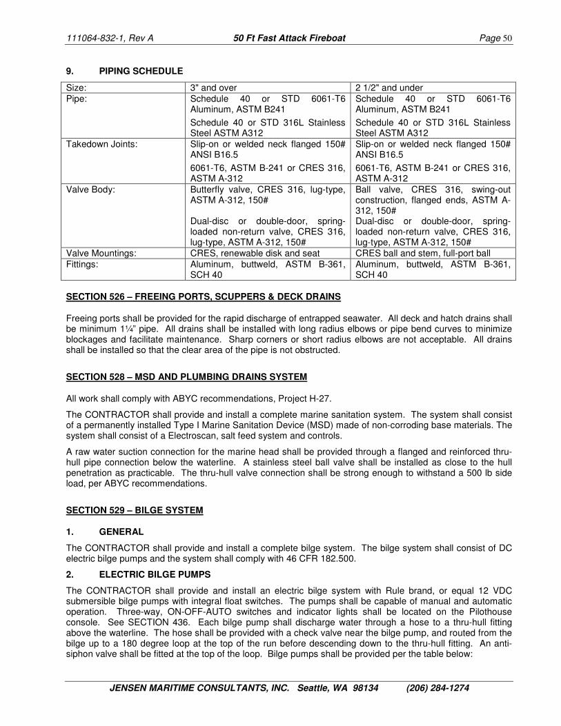
111064-832-1, Rev A 50 Ft Fast Attack Fireboat Page 50
JENSEN MARITIME CONSULTANTS, INC. Seattle, WA 98134 (206) 284-1274
9. PIPING SCHEDULE
Size: 3" and over 2 1/2" and under Pipe: Schedule 40 or STD 6061-T6
Aluminum, ASTM B241
Schedule 40 or STD 316L Stainless Steel ASTM A312
Schedule 40 or STD 6061-T6 Aluminum, ASTM B241
Schedule 40 or STD 316L Stainless Steel ASTM A312
Takedown Joints: Slip-on or welded neck flanged 150# ANSI B16.5
6061-T6, ASTM B-241 or CRES 316, ASTM A-312
Slip-on or welded neck flanged 150# ANSI B16.5
6061-T6, ASTM B-241 or CRES 316, ASTM A-312
Valve Body: Butterfly valve, CRES 316, lug-type, ASTM A-312, 150# Dual-disc or double-door, spring-loaded non-return valve, CRES 316, lug-type, ASTM A-312, 150#
Ball valve, CRES 316, swing-out construction, flanged ends, ASTM A-312, 150# Dual-disc or double-door, spring-loaded non-return valve, CRES 316, lug-type, ASTM A-312, 150#
Valve Mountings: CRES, renewable disk and seat CRES ball and stem, full-port ball Fittings: Aluminum, buttweld, ASTM B-361,
SCH 40 Aluminum, buttweld, ASTM B-361, SCH 40
SECTION 526 – FREEING PORTS, SCUPPERS & DECK DRAINS
Freeing ports shall be provided for the rapid discharge of entrapped seawater. All deck and hatch drains shall be minimum 1¼” pipe. All drains shall be installed with long radius elbows or pipe bend curves to minimize blockages and facilitate maintenance. Sharp corners or short radius elbows are not acceptable. All drains shall be installed so that the clear area of the pipe is not obstructed.
SECTION 528 – MSD AND PLUMBING DRAINS SYSTEM
All work shall comply with ABYC recommendations, Project H-27.
The CONTRACTOR shall provide and install a complete marine sanitation system. The system shall consist of a permanently installed Type I Marine Sanitation Device (MSD) made of non-corroding base materials. The system shall consist of a Electroscan, salt feed system and controls.
A raw water suction connection for the marine head shall be provided through a flanged and reinforced thru-hull pipe connection below the waterline. A stainless steel ball valve shall be installed as close to the hull penetration as practicable. The thru-hull valve connection shall be strong enough to withstand a 500 lb side load, per ABYC recommendations.
SECTION 529 – BILGE SYSTEM
1. GENERAL
The CONTRACTOR shall provide and install a complete bilge system. The bilge system shall consist of DC electric bilge pumps and the system shall comply with 46 CFR 182.500.
2. ELECTRIC BILGE PUMPS
The CONTRACTOR shall provide and install an electric bilge system with Rule brand, or equal 12 VDC submersible bilge pumps with integral float switches. The pumps shall be capable of manual and automatic operation. Three-way, ON-OFF-AUTO switches and indicator lights shall be located on the Pilothouse console. See SECTION 436. Each bilge pump shall discharge water through a hose to a thru-hull fitting above the waterline. The hose shall be provided with a check valve near the bilge pump, and routed from the bilge up to a 180 degree loop at the top of the run before descending down to the thru-hull fitting. An anti-siphon valve shall be fitted at the top of the loop. Bilge pumps shall be provided per the table below:

111064-832-1, Rev A 50 Ft Fast Attack Fireboat Page 51
JENSEN MARITIME CONSULTANTS, INC. Seattle, WA 98134 (206) 284-1274
Area Quantity Capacity (each)
Total Capacity
Comments
Chain locker 1 500 gph 500 gph Aft in the compartment, protected from chain Lower Cabin 2 3,700 gph 3,700 gph Mid and Aft in the compartment Engine Room 2 3,700 gph 7,400 gph One mid and one aft in the compartment 1 500 gph 500 gph Located in stbd pump containment area 1 500 gph 500 gph Located in port pump containment area Drive Room 1 3,700 gph 3,700 gph Located fwd. in the compartment
3. PIPING SCHEDULE
Size: All Hose: PVC water hose, Kuri Tec "Tigerflex"
or equal Clamps: Two (2) worm gear hose clamps,
CRES 316, ASTM A-312 Fittings: CRES 316, barbed hose fittings
SECTION 533 – FRESH WATER SYSTEM
None required. See SECTION 644.
SECTION 555 – FIRE EXTINGUISHING EQUIPMENT AND SYSTEMS
1. FIRE SUPPRESSION SYSTEM
The CONTRACTOR shall provide and install a SEA-FIRE MD 1350 M Fire Suppression System or equal in the machinery space of the vessel. The system shall be of manual release type only and shall be charged with FM-200 extinguishing agent. A station for the release mechanism shall be provided inside the pilothouse in an easily accessible location within 3 feet of the door in the aft pilothouse bulkhead. Adequate protection for the release mechanism shall be provided to prevent accidental discharge. Operating instructions shall be posted at the manual release station.
The Fire Suppression System shall be integrated with the engine control system and the machinery ventilation ducting to provide for safe shut down of the main engines before releasing the extinguishing agent and to prevent air from entering the space. (See SECTIONS 251 and 252.)
2. PORTABLE FIRE EXTINGUISHERS
The CONTRACTOR shall provide and install portable fire extinguishers each of the following locations:
1.) Drive Room, within reach of the hatch
2.) Galley; between the galley and the exit to the space
3.) Helm; near steering position
4.) Cabin; between forward shelves and galley
In addition to these location guidelines, portable fire extinguisher locations are to be situated so that a person shall not have to pass through a fire to reach a portable fire extinguisher from any location inside the vessel. Provisions for discharging the portable fire extinguisher into the engine room from outside the space shall be provided without opening the normal access hatches to the space. If a discharge port is used, it shall comply with ABYC. All portable fire extinguishers shall be of USCG type B-1, ANSI/UL 711 type ABC.

111064-832-1, Rev A 50 Ft Fast Attack Fireboat Page 52
JENSEN MARITIME CONSULTANTS, INC. Seattle, WA 98134 (206) 284-1274
SECTION 556 – HYDRAULIC SYSTEM
1. GENERAL
The CONTRACTOR shall provide and install a hydraulic system in accordance with the requirements of the ABYC Project H-30. The system shall power the foam distribution system (SECTION 521), the bow thruster (SECTION 568), the anchor windlasses (SECTION 581), and portable deck equipment (SECTION 699).
The CONTRACTOR shall provide two (2) hydraulic power unit (HPU) pumps and controls, Wesmar or equal, which shall be powered by marine gear PTO. (See SECTION 241.) The hydraulic system shall be sized so that all hydraulic equipment can be operated simultaneously and sufficiently for maximum performance on one pump. The CONTRACTOR shall develop the hydraulic system subject to approval by the OWNER.
At a minimum, the system shall include a clutch, oil reservoir, suction and return fluid filters, flow sensors, pressure gauges and a heat exchanger.
2 PIPING SCHEDULE
Size: All Pipe: USCG Type A1 Hydraulic Hose,
46 CFR 56.60-25, SAE J1942, 3000 psi working pressure
Takedown Joints: Threaded union, ground joint, CRES 316, ASTM A-312, 2000 psi working pressure
Valve Body: Ball valve, CRES 316, threaded ends, ASTM A-312, 2000 psi working pressure
Valve Mountings: CRES, renewable disk and regrindable seat
Fittings: CRES 316, Parker Series 20 or equal, ASTM A-312, SAE J1475, 2000 psi working pressure
SECTION 561 – STEERING SYSTEM
1. GENERAL
The CONTRACTOR shall provide and install a power assist hydraulic steering system. The steering system hydraulics and actuators shall be integral to the water jet drive.
2. STEERING CONTROL
The steering control stations shall include one (1) wheel and (1) joystick at the pilothouse helm and one (1) steering knob and (1) joystick at the remote helm that transmit the operator’s inputs back to the water jet drives via electronic signals. Steering control shall only be possible from one control at any time. Transfer of control shall include means to prevent inadvertent and abrupt changes in control input during the transfer. In the event of a control system casualty or failure, the speed of the main engines shall default to idle, the main reduction gears shall default to the neutral position, and an alarm will activate at the pilot’s station.
SECTION 568 – BOW THRUSTER
The CONTRACTOR shall provide and install one (1) 8-inch diameter Wesmar Vortex V2-8H (15 HP) or equal counter rotating dual prop CRES bow thruster.
Hydraulic power shall be provided by the hydraulic system (SECTION 556) and sized for continuous operation.

111064-832-1, Rev A 50 Ft Fast Attack Fireboat Page 53
JENSEN MARITIME CONSULTANTS, INC. Seattle, WA 98134 (206) 284-1274
SECTION 581 – ANCHOR & ANCHOR HANDLING
The CONTRACTOR shall provide and install two (2) Maxwell Max Grip Model HWC 1500 or equal hydraulic windlasses on the bow.
The CONTRACTOR shall provide and install two (2) 60 pound high tensile Bruce anchors equipped with 20 feet of 3/8" 316 CRES BBB chain and 550 feet of 5/8" open laid three-strand nylon rope, along with connecting links and shackles to form a complete anchor system.
The anchor and anchor rode shall be stowed in the locker as shown on the Plans. See SECTION 671.
SECTION 583 – LIFESAVING EQUIPMENT
The CONTRACTOR shall provide and install two (2) 30-inch diameter U.S. Coast Guard approved ring life buoy, Englund Marine Astoria Oregon or equal, in locations as designated by the OWNER. The vessel name shall be painted on the life buoy. The life buoy bracket shall be aluminum or CRES and shall be designed to permit quick release of the buoy. The buoy shall have secured to it a 15-fathom line.
The CONTRACTOR shall provide the following rescue, survival and safety equipment outfit:
Rescue, Survival & Safety Equipment
Quantity Additional Information
Light, Marker, Distress 2 Ea ACR Electronics Inc. Automatic Crew-Overboard Marker Light Model SM2
Snap hook for marker light lanyard 2 Ea Lifesaving Systems P/N 365 or equal
Throw Bag 2 Ea Lifesaving Systems Model 237P or equal
Snap hook for throw bag 2 Ea Lifesaving Systems P/N 365 or equal
Emergency distress kit 1 Ea Orion MDL# OLI-544
Personal Flotation Devices, Type I, Adult
6 Ea Stearns Merchant Mate I or equal
Personal Flotation Devices, Type I, Youth
2 Ea Stearns Merchant Mate I or equal
Personal Flotation Device, Type II 6 Ea Mustang inflatable MDL# MD3183 Red and Black
Boat safety belt with attachment straps
4 Ea Lifesaving Systems Model# 218 large and 218-1
Knife With Case 4 EA Buck Vantage Force select MDL# 0845BKX-B
Swimmers Harness w/ 70 feet line 1 Ea Lifesaving Systems Model 202 or equal
Personal Retriever 2 Ea ALS-US
Stokes Litter with Flotation 1 Ea CMC Stainless steel Rescue litter
Medevac Board 1 Ea Lifesaving Systems Corporation Model 450 or equal
SeaKits Damage control Kit 1 Ea Landfall #SKDCK
The ring buoy set stowage shall allow for the distress marker light to remain clipped to the ring buoy. The throw bag remains unclipped from the ring buoy but is rapidly clipped to the buoy when needed.
The CONTRACTOR shall provide and install all other USCG required safety equipment.

111064-832-1, Rev A 50 Ft Fast Attack Fireboat Page 54
JENSEN MARITIME CONSULTANTS, INC. Seattle, WA 98134 (206) 284-1274
GROUP 600 - OUTFIT AND FURNISHINGS
SECTION 601 – GENERAL INFORMATION
See SECTION 012 for OWNER furnished equipment.
The CONTRACTOR shall ensure that outfit and furnishings are installed and tested in accordance with this Specification and as required to ensure complete and efficient operation of systems, components, and machinery. Equipment and components shall be installed and tested in accordance with the manufacturer's practices and recommendations. The CONTRACTOR shall ensure equipment and component warranties are not voided.
SECTION 603 – HULL DESIGNATION AND MARKING
1. NAME, HAILING PORT AND LOGO
In addition to those shown on the Plans, visual identification markings shall be provided on the Pilothouse Top. The CONTRACTOR shall provide and install reflective vinyl graphics as follows: hull number, emblems and designation on both sides of the bow and pilothouse. The name, number and hailing port graphics shall be installed on the stern. The OWNER will approve all hull designations and marking prior to installation. If an additional banner and/or logo are furnished by the OWNER, the CONTRACTOR shall install them.
The CONTRACTOR shall install a bow thruster symbol above the bow thruster.
2. BUILDER'S NAMEPLATE
The CONTRACTOR shall supply a builder's plate, cast with raised uppercase letters 1/4-inch in height, shall be installed in the Pilothouse. Label plate shall be at least 4”x6”x3/16”; material shall be aluminum with black letters. The label plate shall contain the following information:
PORTLAND FIRE & RESCUE FAST ATTACK FIREBOAT NAME (To Be Determine)
DESIGNED BY JENSEN MARITIME CONSULTANTS, INC. BUILT BY (SHIPYARD)
(City, State) Month & Year
3. SYSTEMS & MISCELLANEOUS NAMEPLATES
The CONTRACTOR shall install label plates as required to identify important features and operating instructions for all boat operating systems and equipment. Air escape vent terminals, filling or flushing connections and sounding tubes for all tanks and voids shall have label plates mounted on bulkheads adjacent to the fitting. Plates shall not be mounted on the deck. Deck connections shall have engraved labeling on both the plug and body.
Tank capacity information, expressed in terms of gallons, shall be included on label plates for tanks. Tank fills and piping shall be clearly labeled as to their function.
Lifesaving equipment, fire extinguishing equipment, emergency equipment, etc., shall be marked as required to meet U.S. Coast Guard requirements. The OWNER will be responsible for marking OWNER furnished equipment.
4. PLACARDS
The CONTRACTOR shall provide and install a placard to warn of the federal requirements (33 CFR 151.66 - 151.77) for the discharge of trash and garbage into the ocean. The placard(s) must be displayed in a prominent location. The placards shall be at least 4 inches high by 9 inches wide, with 1/8" high lettering. The placards shall include at least the above disposal and discharge requirements. In addition, the placards must include the penalty clause per 33 CFR 151.59, and any pertinent regional, state, or local requirements.

111064-832-1, Rev A 50 Ft Fast Attack Fireboat Page 55
JENSEN MARITIME CONSULTANTS, INC. Seattle, WA 98134 (206) 284-1274
The CONTRACTOR shall provide and install all other USCG required placards. Locations shall be confirmed with OWNER.
SECTION 611 – HULL AND MOORING FITTINGS
The CONTRACTOR shall install all hull fittings with the necessary foundations, mountings and fastenings as shown on the Plans and as specified herein.
1. FENDERING
The CONTRACTOR shall install pusher knees and fixed fendering with ends faired into the hull. The fendering system shall extend around the complete perimeter of the boat except the transom and a second section just above the waterline including swim step.
The knees shall be made of 5-inch trapezoidal wing D-rubber and fixed fendering shall be made of 4-inch trapezoidal wing D-rubber. The fendering shall be attached to the hull in such a manner that it can be removed and replaced without damage. The surface of the fendering shall be smooth with no abrupt transitions, gaps or seams. The D-rubber shall be weld on or bolt on with bolts at each terminal end. Pusher knee and fendering supports and studs shall be welded to the hull with double continuous welds. Coatings shall be applied to the hull prior to fender installation.
The fendering system shall be installed with welded aluminum flush glancing caps to protect the ends of the D-rubber from shearing or pulling away from the hull at the terminal ends. The installation is subject to OWNER approval.
2. HULL FITTINGS
The CONTRACTOR shall provide and install a portable center-pole dive ladder long enough to double as a ladder to reach the pilothouse top, as shown on the Plans. The OWNER will approve final location. When not in use, the dive ladder shall be stowed in a bracket on the back of the house.
The CONTRACTOR and OWNER shall determine which padeyes used for lifting machinery during construction are to be left in place.
3. MOORING FITTINGS
The CONTRACTOR shall provide and install mooring fittings as shown on the Plans. The mooring fittings shall be cast aluminum or fabricated aluminum of robust design. Mooring bitts and cleats shall be mounted on insert plates.
The CONTRACTOR shall construct and install a tow bitt at the break in the main deck as shown on the Plans. The tow bitt shall be designed to support the breaking strength of the towing line.
The CONTRACTOR shall provide and install ten (10) 15" or 16" closed base cleats (5 port and 5 starboard) as shown on the Plans.
The CONTRACTOR shall provide and install two (2) 15" or 16" closed base cleats (1 port and 1 starboard) on the aft locker boxes as shown on the plans. The OWNER will approve the final locations.
3. MOORING & TOWING OUTFIT
The CONTRACTOR shall provide the following mooring and towing equipment outfit:
Mooring and Towing Outfit Quantity Additional Information
Towing Line 1 Ea 350’ x 1” Nylon, 3 strand
Mooring Lines, 2-3/4" circ. DBN x 30 ft
2 Ea
Mooring Lines, 2-3/4" circ. DBN x 60 ft
6 Ea Also used as bridles
Mooring Lines, ½” dia. DBN x 200 ft 2 Ea

111064-832-1, Rev A 50 Ft Fast Attack Fireboat Page 56
JENSEN MARITIME CONSULTANTS, INC. Seattle, WA 98134 (206) 284-1274
Mooring and Towing Outfit Quantity Additional Information
Heaving Lines, 100 ft 3 Ea Life Saving Systems Model 227-H or equal
Fenders, Cylindrical. 4 Ea Min. 10" dia x 30" long pneumatic, Taylor Made Super Gard or equal, with 10 ft x 3/8” dia. DBN tag line
Boat Hook Mounting Clamps 2 Sets
Telescoping Boat Hooks, 8 ft 2 Ea Garelick Floating #55170
Shackle ( 1 ¼” ) Galvanized Steel 4 Ea
Nylite Shackle, Size 4 (Orange) 4 Ea American Group: (800) 227-7673
Stainless Grapnel 2EA
Drogue (sea anchor) 2Ea Englund Marine
Drogue, Bag Flotation 2 Ea Englund Marine
Drogue Tending line, 1 ½” circ. DBN x 200 ft, hardware to include: 316 Stainless Steel 5/16” swivel, 316 Stainless Steel 5/16” screw pin shackle, and ½” plastic thimble spliced into the line at one end.
1 Ea 200 ft length of line to include length of spliced-in thimble
Snap Hook 12 Ea Englund Marine
Snap Hook Tending Line, 2” circ. black, DBN line x 15 ft
1 Ea Line spliced onto the snap hook at one end.
Towing Gear Stowage Case
Case shall contain the following items listed above: Shackle ( 1 ¼” ), Nylite Shackle, Folding Grapnel
1 Ea Pelican Case 1550 P/N 527
Lifesaving Systems
All lines shall be finished neat with no stray fibers. The mooring lines shall have a 12” eye spliced into one end. Lines shall be stowed so they are hanging in coils and securely stowed with Velcro straps or equivalent.
SECTION 612 – HANDRAILS AND LIFELINES
1. GENERAL
The CONTRACTOR shall provide and install fixed handrails, stanchions and lifelines as shown on the Plans. All fixed grabrails, handrails and stanchions shall be sealed to prevent moisture from entering the inside of the pipes.
2. GRABRAILS AND HANDRAILS
The CONTRACTOR shall provide and install interior and exterior grabrails as shown on the Plans. Grabrails shall be 1 1/4" SCH 40 aluminum pipe with a 3" standoff to the center of the pipe.
The CONTRACTOR shall install a sufficient number of grabrails or hand holds within the Pilothouse and Lower Cabin area for personnel safety. The number and location shall be such that a person shall be able to grab a rail standing anywhere in the Pilothouse or Lower Cabin and grab two rails from any seated location. The OWNER will provide on-site direction for the location of grabrails when the CONTRACTOR is ready to install them.
Two (2) grab rails shall be installed on the top of the pilothouse forward above the window mullions.

111064-832-1, Rev A 50 Ft Fast Attack Fireboat Page 57
JENSEN MARITIME CONSULTANTS, INC. Seattle, WA 98134 (206) 284-1274
3. PORTABLE GUARD RAILS
The CONTRACTOR shall provide and install portable stanchions and lines stainless cable w/snap rings across the two (2) side access points as shown on the PLANS and across the bow and at the top of the stairs aft. Wires shall have snap rings and attach with CRES mounting hardware.
SECTION 615 – HARDWARE
The CONTRACTOR shall provide and install all required hardware. Hardware shall be of stainless steel, polished with a bright finish. All items of hardware shall be provided and installed by the manufacturer of the structural doors, hatches, manholes, scuttles and joiner doors.
SECTION 621 – JOINER BULKHEADS & LININGS
The CONTRACTOR shall provide and install joiner type bulkheads in the Lower Cabin in accordance with the Plans. Joiner bulkheads shall be shall be balsa core fiberglass composite panels or equal. All decorative pre-finished surfaces shall be covered for protection during shipment, storage and erection, and until all work has been completed within the space. All non-structural bulkheads, and the associated supporting hardware shall be free from sharp or rough edges.
SECTION 622 – FLOOR PLATES AND GRATINGS
The CONTRACTOR shall provide and install grating plates in the anchor locker to support the anchors & line.
The CONTRACTOR shall provide and install floor plates in the Lower Cabin. Floor plates shall be 3/4" PVC core fiberglass composite panels or equal. Floor plates shall be designed to withstand a minimum uniform loading of 100 pounds per square foot over the entire floor. Floor plates shall be bolted to structure and shall be mounted on 3” x ¼” neoprene gasket material to reduce vibration. Access panels shall be supplied as necessary to inspect all cable penetrations and to access all equipment and tanks mounted below the deck plates.
The CONTRACTOR shall provide and install removable, securely mounted, non-skid floor grating plates in the Engine Room and Drive Room to facilitate maintenance and inspection. Grating shall be light weight, fire resistant Fibergrate XFR, or equal with quick release removable (without tools) panels. Material and layout is subject to OWNER approval.
Areas that will be used as steps during routine operations or maintenance shall be provided with a non-skid surface that shall be 3M Safety Walk Coarse 770 (color: Deck Grey).
SECTION 623 – LADDERS AND GANGWAYS
The CONTRACTOR shall provide and install one aluminum inclined ladder, rungs, and steps to access the Lower Cabin from the Pilothouse. The ladder shall be provided with grab rails on both sides of the ladder, 36 inches above the center of the treads, and a grab rail overhead. The inclined ladder shall be removable. The inclined ladder shall have extruded, non-slip, ribbed aluminum, evenly spaced nine inch treads. Ladder pitch shall be as shown on the Plans.
The CONTRACTOR shall provide and install steps or ladder rungs and grab rails for access to the anchor locker and Pilothouse top.
The CONTRACTOR shall provide and install steps or ladder rungs to access the Engine Room in three places and to access the Drive Room in one place. At least one access route to each space shall be sufficiently clear of equipment for entrance when the vessel is moving.

111064-832-1, Rev A 50 Ft Fast Attack Fireboat Page 58
JENSEN MARITIME CONSULTANTS, INC. Seattle, WA 98134 (206) 284-1274
SECTION 631 – PAINTING
1. GENERAL
The CONTRACTOR shall prepare all exposed aluminum surfaces on the exterior of the craft with a uniform natural or satin finish. The exterior of the hull and cabin shall remain bare aluminum finish.
All paint formulation, specification, surface preparation, environmental constraints and application, including minimum dry film thickness (DFT) shall be in accordance with the paint manufacturer's recommendation and warranties. The CONTRACTOR shall provide a complete Paint Schedule to the OWNER for approval. The CONTRACTOR shall not commence any paint application prior to the OWNER's approval of the Paint Schedule. The paint performance, including but not limited to anti-fouling performance, shall be fully warranted by the CONTRACTOR.
The OWNER will furnish the painting color scheme within forty-five (45) days of contract award.
All surfaces, including items of machinery and equipment, which become damaged or soiled during construction shall be cleaned, and the coating renewed as required to conform to the surrounding paint system.
Other than touch-up, painting is not required for electrical and electronic equipment, furniture, furnishings, machinery, and other items that are delivered with permanent factory coatings (baked-on enamels) or synthetic finishes that are of colors required by the Plans or this Specification. Exterior machinery and equipment (factory painted) that does not conform to the colors specified by the Plans shall be painted to conform to the required color.
2. SURFACE PREPARATION
All aluminum surfaces to be painted shall be thoroughly cleaned to near white bare metal, free of corrosion products, dirt, and other contaminants, by light abrasive blasting or grinding. Spot cleaning after blasting or grinding can be accomplished by power brushing or orbital sanding. Only clean dry sand, stainless steel wire brushes, stainless steel pads, or P-E-455 specification abrasive sanding discs that have not been previously used on other metals or for removal of copper or mercury pigmented paints shall be used to clean the aluminum. If not painted immediately, or if contaminated with oil or grease, the aluminum should be washed with a liquid detergent cleaner, thoroughly rinsed with fresh water, and allowed to dry completely. The CONTRACTOR shall notify the OWNER prior to painting and the painting shall not proceed until the area has been inspected and approved by the OWNER'S REPRESENTATIVE.
3. PAINTING SCHEDULES
Coatings shall be in accordance with the following schedules. Where "E-Paint" is used in the schedules it indicates the products of the ePaint Company. Where "Ameron" is used in the schedules it indicates the product of Ameron International – Performance Coatings and Finished Group, an Ameron International Company.
All coatings shall be applied per manufacturer’s specifications with regard to preparation, environmental conditions and application.
The CONTRACTOR shall sandsweep surfaces with garnett or aluminium oxide (20/40 mesh) to achieve a 1-2 mil profile.
Colors are for guidance only. OWNER shall have final approval authority for all colors. Colors on multiple coats of epoxy primer shall be of a differing shade.
Non-skid shall be applied on all exterior horizontal surfaces except as directed by the OWNER. Areas with non-skid shall have HS Ameron epoxy topcoat with polybeads or equal. In general, non-skid shall be applied to within 2" of a vertical bulkhead or deck structure.
A. Hull below a waterline 6” above design waterline, exterior, including appendages:
• Apply 1st full coat of E-Paint EP-Prime 1000 two-part epoxy primer, white @ 4-5 mils DFT • Apply 2nd full coat of E-Paint EP-Prime 1000 two-part epoxy primer, haze gray @ 4-5 mils DFT • Apply 3rd full coat of E-Paint EP-Prime 1000 two-part epoxy primer, oxide red @ 4-5 mils DFT

111064-832-1, Rev A 50 Ft Fast Attack Fireboat Page 59
JENSEN MARITIME CONSULTANTS, INC. Seattle, WA 98134 (206) 284-1274
• Apply 4th full coat of E-Paint No-Foul ZO red antifouling @ 3-4 mils DFT • Apply 5th full coat of E-Paint No-Foul ZO gray antifouling @ 3-4 mils DFT • Apply 6th stripe coat of E-Paint No-Foul ZO blue antifouling @ 3-4 mils DFT on leading edges • Apply 7th full coat of E-Paint No-Foul ZO black antifouling @ 3-4 mils DFT
Paint on the underwater portion of the hull and appendages and accumulation of marine growth shall not be more than 45 days old at the time of vessel DELIVERY to the OWNER.
B. Hull above waterline, exterior:
• Clean the aluminum with Sharkhide Aluminum Cleaner • Polish with Sharkhide Aluminum Polish • Protect with a full coat of Shark Hide Metal Protectant.
C. Requirements for thermal coatings are described in SECTION 635.
SECTION 633 – CATHODIC PROTECTION
The CONTRACTOR shall install one (1) complete Electro-Guard Model 705 cathodic protection monitoring and control system. The system shall include an instrument panel monitor/controller with four (4) anodes and one (1) mounted reference cell installed below the waterline. Installation of the impressed current cathodic protection system shall strictly adhere to the manufacturer's recommendations and instructions. Special attention shall be paid to the dielectric shield at each anode location and an epoxy barrier shall be installed to reduce the load on the impressed current cathodic protection system. The OWNER shall approve all anode locations.
SECTION 634 – DECK COVERING
The CONTRACTOR shall install the following:
• Soundmat acoustic floor covering w/wear resistant mat top layer, or equal, in way of Pilothouse, • PVC free rubber non-skid floor tiles, 0.080” Flexco Flextones Hammered, or equal, elsewhere.
Color to be approved by OWNER.
SECTION 635 – INSULATION, HULL AND PIPING
1. GENERAL
The CONTRACTOR shall provide and install hull insulation as specified herein. Duct insulation shall be the board type for rectangular ducts and the blanket type for round ducts.
Fastenings shall not crush or otherwise reduce the insulating value of the insulation. Spacing of weld pins and studs shall be 12 inches maximum. Weld pins and studs shall not be more than 12 inches from edges or joints of insulation.
Vapor barriers shall be applied to all insulation as necessary to prevent penetration of moisture. Vapor barriers shall remain intact and continuous over the area protected by means of sealed joints and edges. There shall be no holes or voids in any single coat of vapor barrier coating. Sheathing shall be installed where necessary to protect insulation
Insulation applied to weather boundaries shall be extended to cover adjoining bulkheads, the overhead or other structural members for a distance of 12 inches inboard of the weather boundary. In order to provide full contact with faying surfaces and prevent voids, fit insulation tightly to surface to be insulated. Insulation and sheathing in way of equipment requiring servicing and maintenance shall be removable and replaceable without use of additional material. Board type insulation removed locally to provide contact of faying surfaces

111064-832-1, Rev A 50 Ft Fast Attack Fireboat Page 60
JENSEN MARITIME CONSULTANTS, INC. Seattle, WA 98134 (206) 284-1274
in way of small projections shall be minimal. Corners shall be cut square and butt joints shall be flush, straight and smooth. Dissimilar metals must be isolated from each other to prevent electrolysis.
Insulation shall be installed over watertight boundaries only after all specified tightness tests have been completed.
Hatches and doors and other access closures shall be thermally insulated equal to that of the adjacent structure. The area around operating parts and the inside surfaces of coamings shall be treated wherever possible with anti-sweat treatment.
2. THERMAL INSULATION
Provide and install thermal insulation on the interior side of all exterior boundaries of the Pilothouse and Lower Cabin. Thermal insulation shall consist of two materials:
• Delta T Marine Thermal Coating, 40 mil DFT on plating, 60 mil DFT on stiffeners, throughout • Fiberglass Hullboard, 1 lb/cu ft, 2 inches thick w/mylar facing, Microlite or equal, above chine
Application of coatings shall be in strict accordance with the manufacturer's recommendations. An acrylic topcoat shall be applied over the thermal coating where it is not covered with insulation or a liner.
3. ACOUSTIC INSULATION
Provide and install acoustic insulation on all boundaries between the Engine Room or plenum and the Pilothouse or Lower Cabin and on the main deck from the forward engine room bulkhead to the frame at the forward end of the main deck hatches (full width of deck) as follows:
• Delta ~dB Marine Damping Coating, 80 mil DFT on 70% of plating area between stiffeners, • Fiberglass Hullboard, 3 lb/cu ft, 2 inches thick w/mylar facing, Microlite or equal, in plenum, • Fiberglass Hullboard, 3 lb/cu ft, 4 inches thick w/mylar facing, Microlite or equal, elsewhere.
Provide and install acoustic insulation on the main deck from the frame at the forward end of the main deck hatches (full width of deck) to the aft end of the engine room as follows:
• Polyimide flexible open cell foam, 0.38 lb/cu ft, 1 inch thick w/white mylar facing, Soundown LCF or equal.
Application of coatings shall be in strict accordance with the manufacturer's recommendations.
SECTION 637 – SHEATHING
The CONTRACTOR shall provide and install light weight sheathing to cover and protect insulation on all bulkheads, interior sides and ceilings in the Pilothouse and Lower Cabin spaces. The edges of sheathing shall be finished by aluminum trim that provides a smooth edge completely covering the cut edges of the sheathing. Access panels shall be provided to access all wiring and removable pipe runs. Sheathing subject to OWNER approval.
SECTION 644 – SANITARY SPACES AND FIXTURES
The CONTRACTOR shall provide and install a marine head, Raritan PHEII or equal, in the head space as shown on the plans. The vent pipe from the head shall be routed to a weather terminal above the Lower Cabin top. Pipe routing shall be approved by the OWNER.
The CONTRACTOR shall provide and install a sink Sterling Polar 131-0 or equal, with a sump tank, Rule pump and float switch. Discharge shall be plumbed overboard. The contractor will construct a shelf above the sink for the fresh water tank. See SECTION 123.
111064-832-1, Rev A 50 Ft Fast Attack Fireboat Page 61
JENSEN MARITIME CONSULTANTS, INC. Seattle, WA 98134 (206) 284-1274
SECTION 661 – PILOTHOUSE AND LOWER CABIN
1. GENERAL
The Pilothouse and Lower Cabin spaces shall be arranged and constructed as shown on the Plans. The CONTRACTOR shall construct and provide and install all equipment and furnishings in accordance with the Plans and as specified herein.
The overhead height of the Pilothouse and Lower Cabin area shall be a minimum of 6'-10" in all walking areas.
Wiring shall not be exposed but shall be easily accessible. Any panels that may require removal shall be easily removable. Access panels and wireways shall be latched with Aimsco 1/4-turn closures or equal with Phillips heads.
All furniture shall be vermin and cockroach-proofed to conform to regulations of the U. S. Public Health Service. All drawers, chests and hatches shall have hooks and stops, and drawers shall have spring catches in order to prevent them from opening when underway.
2. INTERIOR DECOR
The CONTRACTOR shall provide and install all interior decor. Prior to purchasing or installing the decor, the CONTRACTOR shall propose the interior decor scheme to the OWNER for approval. The decor and materials shall be designed to be as maintenance free as possible. A recommended interior schedule is as follows:
Item Manufacturer Joiner bulkheads/cabinetry Light gray Zolatone, or equal, with clear coat seal Laminate for counters/consoles Larkspur D328-6, or equal Cabin soles, kicks and baseboards Rhinoliner or equal polyurethane coating
(extending 24” above deck level) Pilothouse chair & bench upholstery Boltoflex Nautolex series upholstery, black or dark gray Deck lockers, fwd and aft Tufflex or equal
3. PILOTHOUSE SEATING
The CONTRACTOR shall provide and install four (4) shock mitigating chairs with padded arm rests and seat belts, Stidd 500V5 or equal as shown on the Plans. Standard sports water bottle holders shall be provided near each seat.
Both the Pilot’s and Officer’s seats must be on a track so they can be pushed back out of the way so the crewmember can stand at their station.
Seat materials shall provide comfortable support of the seated person and shall be fabricated of durable marine grade materials. Materials shall be resistant to tearing and puncturing, and not significantly degrade or fade under exposure to sunlight and saltwater. Material subject to OWNER approval.
Pilothouse bench seating shall be fabricated and installed as shown on the Plans. The bench seats shall be padded (firm) and upholstery fabric shall match Pilothouse chair upholstery fabric.
4. GALLEY
The CONTRACTOR shall provide and install the following in the galley area in the lower cabin:
• Microwave, 0.7 cf, 1200 W, • Refrigerator, 3.6 cf Norcold DER788S, or equal, • Paper towel dispenser, • Trash can with lid, self-closing, • Handi-wipes type dispenser, • Cabinet storage space, 1 cf
Both the microwave and refrigerator shall operate while on shore power or underway.

111064-832-1, Rev A 50 Ft Fast Attack Fireboat Page 62
JENSEN MARITIME CONSULTANTS, INC. Seattle, WA 98134 (206) 284-1274
5. HEAD
The CONTRACTOR shall provide and install the following in the head area in the lower cabin:
• Grab rails, • Toilet paper holder, • Trash can with lid, small, self-closing, • Handi-wipes type dispenser
Both the microwave and refrigerator shall operate while on shore power or underway.
SECTION 671 – STOWAGE SPACES
The CONTRACTOR shall provide and install miscellaneous stowage in accordance with the Plans and as described below. All stowage shall be adequate to prevent spillage in a seaway. The OWNER will approve the final arrangements.
A. Provide stowage for a washdown hose, fire hoses and other deck equipment in the seat lockers at the stern.
B. Provide stowage for fire hose in a hose bed and other fire fighting equipment on a shelf above the hose bed in the forward equipment locker.
C. Provide stowage shelves in the Lower Cabin spaces as shown on the Plans.
D. Provide a counter with drawers and shelves in the Lower Cabin spaces as shown on the Plans.
E. Provide crew and/or patient transport bench seating with stowage below in Pilothouse as shown on the Plans. The bench seat shall have storage under the seat in any space available inboard and/or above the engine air intake trunk. Shelving configuration shall be approved by the OWNER.
Two (2) seatbelts shall be provided to secure patients on the bench on the port side. The seatbelts shall consist of four (4) permanently mounted CRES folding padeyes and two (2) double-ended straps with CRES snap clips.
F. Provide brackets and retention straps to stow SCBA equipment, qty 4, in the Lower Cabin. Provide stowage tubes to stow four (4) spare SCBA bottles. All locations to be approved by the OWNER.
G. Provide shelves with retaining bar for 12”x12” binders (notebooks) in the Lower Cabin.
H. Provide stowage for the anchor lines on a grating platform and anchors in brackets in the forepeak anchor locker for the anchor system described in SECTION 581.
I. Provide two hose racks in the Engine Room as shown on the Plans. Dimensions of hose rolls will be provided by the OWNER.
SECTION 699 – MISCELLANEIOUS OUTFIT
The CONTRACTOR shall provide the following general outfit:
• One towline reel, • One anchor line reel, and • Two (2) trash / wash-down hydraulic pumps, Pacer S Series, or equal.
The CONTRACTOR shall install the trash / wash-down pumps in the drive room. The pump will be fitted with a through-hull connection fitted with an aluminum strainer and a three-way CRES valve. The valve will be selectable to “wash-down”, “suction” or “off”. The discharge side of the pump and the suction side of the three-way valve shall have fittings approved by the OWNER. Materials shall comply with piping schedule provided in SECTION 521.
Special tools that are required for underway repairs and frequent preventive maintenance shall be provided and stored with the onboard spares.

111064-832-1, Rev A 50 Ft Fast Attack Fireboat Page 63
JENSEN MARITIME CONSULTANTS, INC. Seattle, WA 98134 (206) 284-1274
The CONTRACTOR shall provide the following:
General Outfit Quantity Additional Information
Ensign, National (16”x24”) 1 Ea
Pike poles 6’,8’,12’ 2 of Ea Aluminum Handles
Fireboat Operator’s Handbook 4
Hearing Protectors, Ear Muff Style (pair)
4 Peltor H10 Series Twin Cup Ear Muff or equal
Hearing Protectors, Foam Insert Type, Disposable, Corded
1 Box NSN 6515-00-137-6345
Flashlight, Pelican non-explosive 4 Ea Lifesaving Systems P/N-LS #605 (Pelican Saberlite)
Searchlight, Weather resistant, Hand-Held, Rechargeable Battery
2 Ea Golight profiler II
MDL 8130
Blankets, Wool 4 Ea
Blankets, Emergency 4 Ea Life Savings Systems Model 387P (SPACE ® Emergency Blanket) or equal
Binoculars, 8 x 30 Marine Waterproof
4 Ea Steiner Navigator
Tool Box
1 Ea Craftsman - Item# 000982489000, MDL# 82489
Tools 1 Ea Craftsman - Item# 009HO252000B, MDL# HO252
SEPAR LID GASKET 2 Ea
250 CLASS T FUSE 1 Ea
LIGHT,UTILITY,VEHICULAR 1 Ea
MDE R/W PUMP COVER GASKET
1 Ea
MDE R/W IMPELLER 1 Ea
SECONDARY FUEL FILTER 2 Ea
DIVIDED CASE 1 Ea
FUEL FILTERS 2 Ea Stored in divided case.
FUSE,CARTRIDGE 3 Amp 1 Ea Stored in divided case.
FUSE,CARTRIDGE 5 Amp 1 Ea Stored in divided case.
FUSE, CARTRIDGE 6 Amp 1 Ea Stored in divided case.
FUSE,CARTRIDGE 10 Amp 1 Ea Stored in divided case.
FUSE,CARTRIDGE 15 Amp 1 Ea Stored in divided case.
FUSE,CARTRIDGE 30 Amp 1 Ea Stored in divided case.
FUSE,CARTRIDGE 1 Amp 1 Ea Stored in divided case.
FUSE,CARTRIDGE 3 Amp 1 Ea Stored in divided case.
FUSE,CARTRIDGE 4 Amp 1 Ea Stored in divided case.
FUSE,CARTRIDGE 5 Amp 1 Ea Stored in divided case.
FUSE,CARTRIDGE 10 Amp 1 Ea Stored in divided case.
FUSE,CARTRIDGE 20 Amp 1 Ea Stored in divided case.

111064-832-1, Rev A 50 Ft Fast Attack Fireboat Page 64
JENSEN MARITIME CONSULTANTS, INC. Seattle, WA 98134 (206) 284-1274
The CONTRACTOR shall provide fabric covers for the following:
• Towline reel, • Anchor line reel
Covers shall be fabricated of red Top Gun fabric or equal. Covers shall be provided with a means of securing them in place under all operational conditions. When not in use, stowage for the cover shall be provided adjacent to the item being covered.
111064-832-1, Rev A 50 Ft Fast Attack Fireboat Page 65
JENSEN MARITIME CONSULTANTS, INC. Seattle, WA 98134 (206) 284-1274
GROUP 800 - DESIGN AND ENGINEERING SERVICES
SECTION 813 – CONSTRUCTION SCHEDULE
Within fourteen (14) days after award of contract, the CONTRACTOR shall prepare a Master Construction Schedule using Microsoft Project and submit the schedule to the OWNER.
The Master Construction Schedule shall show the proposed start and completion dates for the development of working plans, lofting, fabrication, assembly, erection and/or installation of the principal items and systems that comprise the vessel. It shall include, but not be limited to, the major hull structural sections, machinery components, piping systems, electrical items and systems, electronic systems, ventilation systems, and joinery items. As a minimum, the following submittals and key events shall be included:
Phase I:
• Drawing/Document Schedule with submittal dates • Material/Equipment Ordering Schedule • OWNER Furnished Equipment (OFE) Delivery Schedule • CONTRACTOR’s Weight Estimate (CWE) submittal date • Meeting to agree on final speed/power and weight performance
Phase II:
• Lofting commencement and completion • Hull construction commencement • Engines, jets, fi-fi pumps and monitors ordered/received in shipyard • OWNER Furnished Equipment required in shipyard • Hull construction completion • Engine installation • Superstructure completion • Fire fighting piping installation • Fire fighting system completion • Pre-Closing inspections required • Propulsion system ready for testing • Propulsion system startup • Fire fighting system startup • Lightship weight determination (scale weighing) • Launch • Stability test • Dock trials • Deadweight survey for Sea Trials Condition • Sea Trials • DELIVERY • Crew Training
All prefabrication work to be accomplished as part of the construction effort shall be clearly indicated on the Master Construction Schedule.
The CONTRACTOR shall prepare and submit a Material/Equipment Ordering Schedule. The Material Ordering Schedule shall include the item, the planned and actual order dates, and the supplier name and telephone number for items ordered.
In the event that a Contract Change Order alters the scheduled DELIVERY of the Vessel, the CONTRACTOR shall revise the Master Construction Schedule to show the changes in scheduling and submit the revised schedule to the OWNER.

111064-832-1, Rev A 50 Ft Fast Attack Fireboat Page 66
JENSEN MARITIME CONSULTANTS, INC. Seattle, WA 98134 (206) 284-1274
On a bi-weekly basis, the CONTRACTOR shall submit to the OWNER a progress schedule indicating the actual progress achieved in comparison to the planned progress required by the Master Construction Schedule.
SECTION 832 – TECHNICAL MANUALS
1. TECHNICAL MANUALS AND COMPUTER HARDWARE & SOFTWARE
Technical manuals for purchased equipment shall be supplied to the OWNER upon DELIVERY of vessel.
Two hard copies and four electronic copies (on CD) of all major equipment service manuals (including owners, operators, application, installation, service and parts manuals) shall be obtained with the major CONTRACTOR furnished equipment. One hard copy is for the vessel, hardcopy, bound where practical. One hard copy is for the OWNER.
The CONTRACTOR shall provide one copy of propulsion and fire engine diagnostic software with communication connectors/adaptor hardware. The CONTRACTOR shall provide training on use of the diagnostic software for nine people.
The CONTRACTOR shall provide two (2) copies of Autodesk DWF Composer, latest version and any other software (Rhino, Solid Works) necessary to view and mark-up drawings/models developed by the CONTRACTOR as required by SECTION 007. The software version provided shall not be limited use. One copy of each software package shall be provided to the OWNER’S REPRESNTATIVE at the start of the project.
The CONTRACTOR shall provide one (1) copy of Microsoft Office Professional, latest version.
The CONTRACTOR shall provide a laptop computer, Panasonic Toughbook 31 i5 or equal. The laptop computer shall be provided with an operating system compatible with the engine diagnostic software, Microsoft Office, Autodesk DWF Composer, and other provided software and shall have a 320 GB hard drive.
The CONTRACTOR shall load all software.
2. EQUIPMENT INFORMATION AND CONTACT ADDRESSES
For all CONTRACTOR furnished equipment, information such as suppliers name, address, phone and fax numbers, model number, serial number, etc. shall be gathered in ring binders. One set shall be provided to the OWNER and one set to the vessel.
The propulsion system final alignment report (SECTION 233) and the sea trial report (SECTION 982) shall be compiled and placed in the binder.
3. TRAINING
The CONTRACTOR shall provide engine vendor certified training on site in Portland after DELIVERY for nine people on machinery and related systems operations, troubleshooting and routine maintenance. The schedule shall be approved by the OWNER.
The CONTRACTOR shall provide training by shipyard personnel on operations and maintenance of vessel. The CONTRACTOR shall provide three training sessions of two days each on vessel operations and maintenance of every system. The curriculum and schedule shall be approved by the OWNER.
4. DRAWINGS
The CONTRACTOR shall provide two complete sets of all the final drawing. In addition, one set of the required “As-Built” drawings (SECTION 007) shall be laminated and delivered with the vessel.
The CONTRACTOR shall provide one electronic copy of each drawing. The drawings shall be provided on CD-ROM, in AutoCAD 2007 and/or other software formats compatible with provided software. Disks shall have printed labels identifying the drawing number(s), drawing title(s), vessel identification, and date. Drawing file names shall be clear and consistent so that the file name readily identifies the applicable drawing number.
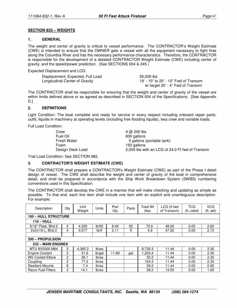
111064-832-1, Rev A 50 Ft Fast Attack Fireboat Page 67
JENSEN MARITIME CONSULTANTS, INC. Seattle, WA 98134 (206) 284-1274
SECTION 833 – WEIGHTS
1. GENERAL
The weight and center of gravity is critical to vessel performance. The CONTRACTOR’s Weight Estimate (CWE) is intended to ensure that the OWNER gets a vessel with all the equipment necessary to fight fires along the Columbia River and has the necessary performance characteristics. Therefore, the CONTRACTOR is responsible for the development of a detailed CONTRACTOR Weight Estimate (CWE) including center of gravity, and the speed/power prediction. (See SECTIONS 004 & 245.)
Expected Displacement and LCG:
Displacement, Expected, Full Load 55,000 lbs Longitudinal Center of Gravity 19’ - 10” to 20’ - 10” Fwd of Transom
w/ target 20’ - 4” Fwd of Transom
The CONTRACTOR shall be responsible for ensuring that the weight and center of gravity of the vessel are within limits defined above or as agreed as described in SECTION 004 of the Specifications. [See Appendix D.]
2. DEFINITIONS
Light Condition: The boat complete and ready for service in every respect including onboard repair parts, outfit, liquids in machinery at operating levels (including free flooding liquids), less crew and variable loads.
Full Load Condition:
Crew 4 @ 200 lbs Fuel Oil 600 gallons Fresh Water 5 gallons (portable tank) Foam 150 gallons Design Deck Load 2,000 lbs with an LCG of 24.0 Ft fwd of Transom
Trial Load Condition: See SECTION 982.
3. CONTRACTOR'S WEIGHT ESTIMATE (CWE)
The CONTRACTOR shall prepare a CONTRACTOR's Weight Estimate (CWE) as part of the Phase I detail design of vessel. The CWE shall describe the weight and center of gravity of the boat in comprehensive detail, and shall be prepared in accordance with the Ship Work Breakdown System (SWBS) numbering conventions used in this Specification.
The CONTRACTOR shall develop the CWE in a manner that will make checking and updating as simple as possible. To that end, each line item shall include one item with an explicit and unambiguous description. For example:
Description Qty Unit Weight
Units Part Qty
Parts Total Wt (lbs)
LCG (ft fwd of Transom)
TCG (ft,+stbd)
VCG (ft, abl)
100 – HULL STRUCTURE
110 – HULL
5/16” Plate, Bhd 2 2 4.320 lb/ft2 8.40 ft2 72.6 48.00 0.00 2.60 2x2x1/8 L, Bhd 2 4 0.577 lb/ft 2.11 ft 4.9 47.92 0.00 2.72
200 – PROPULSION
233 – MAIN ENGINES
MTU 8V2000 M84 2 4,365.2 lb/ea 8,730.3 11.44 0.00 2.30 Engine Coolant 2 51.6 lb/gal 11.89 gal 1,203.4 11.44 0.00 2.30 Wtr Cooled Elbow 2 26.1 lb/ea 52.2 11.44 0.00 2.30 Coupling 2 77.2 lb/ea 154.3 11.44 0.00 2.30 Resilient Mounts 8 7.4 lb/ea 59.2 11.44 0.00 0.95 Racor Fuel Filters 2 14.1 lb/ea 28.2 13.50 0.00 1.65

111064-832-1, Rev A 50 Ft Fast Attack Fireboat Page 68
JENSEN MARITIME CONSULTANTS, INC. Seattle, WA 98134 (206) 284-1274
The OWNER will provide weights of OFE items.
Prior to the completion of Phase I, the CWE will be checked and approved by the OWNER as outlined in SECTIONS 007 and 101. The CONTRACTOR shall provide:
• Vendor correspondence/specifications to substantiate the materials list on the WORKING PLANS, • Working Plans with weight as described in SECTION 007, • Models or calculations used to develop the weight estimate, and • CONTRACTOR’S Weight Estimate.
Once the CWE is accepted at the end of Phase I, the only changes to the contract weight will be by incorporation of accepted Change Orders. (See SECTION 010.)
4. MARGINS AND ALLOWANCES
The CONTRACTOR shall develop the Working Plans to a level of detail that will provide a high level of confidence in the CWE. Each structural element type and piece of equipment that can be identified and measured or weighed shall be included as a line item in the CWE. Items that must be estimated shall be called out separately with a note describing the estimation method. Items that cannot be reasonably estimated will be included as Allowances. The following allowances shall be used unless the CONTRACTOR can provide evidence that another value should be used:
• Allowance for Weld & Mill Tolerance 3.5% of Aluminum Weight • Allowance for Brackets 0.5% of Aluminum Weight • Allowance for Wire Hangers 2.0% of Wire Weight • Allowance for Pipe Hangers 0.5% of Pipe Weight
The CONTRACTOR shall develop the design to the point that the CONTRACTOR is confident enough to use only the following margins:
• OFE Margin 3.0% of Owner Furnished Equipment Weight • Vendor Margin 3.0% of Vendor Supplied Equipment • Construction Margin 3.0% of Estimated Lightship
5. WEIGHT CONTROL PROGRAM
The CONTRACTOR shall prepare and implement a comprehensive weight control program for the construction of the boat to ensure that the boat is delivered within the weight and center of gravity requirements set forth in this Specification (as agreed upon with the acceptance of the CWE). The basic requirements of the Weight Control Program include:
• All purchase orders for major equipment shall require vendors to submit information on the net weight and location of the center of gravity of all of the proposed equipment to be installed on the boat.
• The purchase order for the lofting package shall require the vendor to (a) use the same reference point (transom, centerline, baseline) for the lofting package as for the CWE and (b) submit weight and CG information for each assembly or sub-assembly on the assembly drawings.
• The purchase order for the spooling package, if any, shall be the same as for lofting. • All vendor-supplied components, including both CONTRACTOR and OWNER furnished, in excess of
20 lbs. shall be weighed prior to installation on the vessel to verify calculated or vendor supplied weights.
• All insulation, sheathing, joinery, deck covering or other materials estimated by area shall be weighed prior to installation to obtain actual unit weights.
As the above weight information becomes available, the weight control manager shall incorporate the information with the CWE. In the spreadsheet, to the right of the CWE information described in the table above (SECTION 833/3), additional columns shall be added to record the actual unit weights, total weights and centers of gravity and the magnitude of the weight differences. The spreadsheet shall be configured in such a way as to provide both the CWE weight and center and the most current expected final weight based on the weight control plan updates.

111064-832-1, Rev A 50 Ft Fast Attack Fireboat Page 69
JENSEN MARITIME CONSULTANTS, INC. Seattle, WA 98134 (206) 284-1274
During Phase II construction of the vessel, the CONTRACTOR shall submit Weight Control Reports comparing actual weights to the CWE at two week intervals. The weight control reports shall include updated entries for items which have been weighed and corrections to boat weight based on design or construction modifications. The Weight Control Reports shall accurately reflect the condition of the boat within 5 days of the submittal date. The CONTRACTOR shall submit Weight Report Supporting Data and Calculations with each weight report submitted, including margin adjustments. Particular notation shall be made of any item weight discrepancy in excess of 3%.
6. SCALE WEIGHING
The CONTRACTOR will scale weigh the vessel after Builder's Trials (see SECTION 982). The vessel shall be weighed by lifting simultaneously with at least two scales to determine total weight and longitudinal center. The vessel shall be completely outfitted as for builder's trials except as required for safety of personnel and equipment.
The scales used for the lift shall be certified scales, accurate to within plus or minus .5% of full-scale reading. Certification shall be traceable to the National Bureau of Standards or sealed by the state or county agency cognizant for weights and measures within the statutory period required by the agency for use in trade. The total maximum reading of the scales shall not exceed four times the estimated weight of the vessel.
The scale weighing report shall include:
A. A dimensioned sketch of the scale locations relative to the vessel, the readings of the scales, their serial numbers and certification and calibration information, tares and centers of the lifting rigging and the computed weight and longitudinal center of the vessel as weighed.
B. Weights and longitudinal and vertical centers of gravity of all extraneous equipment, liquids, and other deadweight items, not part of the boat's lightship.
C. Weights and longitudinal and vertical centers of gravity of all missing equipment, liquids, and other deadweight items, that are part of the boat's lightship.
7. “AS-BUILT” CONTRACTORS WEIGHT ESTIMATE
A final "as-built" CWE shall be submitted to the OWNER not later than 30 days after DELIVERY of the vessel. The as-built CWE shall incorporate data from the full-scale boat weighing and the stability test for comparison to the estimated values.
SECTION 839 – LOFTING
The hull, superstructure and masts shall be numerical control (NC) lofted at the expense of the CONTRACTOR. The CONTRACTOR shall take full responsibility for all lofting.
The loft faired hull lines shall be submitted to the OWNER for approval prior to commencement of construction. All shell plate straking arrangements shall be subject to approval by the OWNER. The CONTRACTOR shall supply the OWNER with a copy of the lofting drawings and NC cutting tapes upon completion of the project, for OWNER records. The OWNER shall have the right to build additional vessels from the lofting information.
SECTION 843 – STABILITY
1. GENERAL
The CONTRACTOR shall provide calculations that demonstrate that the vessel will survive one-compartment damage in accordance with NFPA 1925 requirements for a Type III marine fire-fighting vessel at the full load displacement (SECTION 833/2) based on the CWE. If the final vessel displacement exceeds the CWE value or if the final LCG differs from the CWE LCG by more than 6”, the calculations shall be revised to demonstrate compliance.
Static list of the boat in the full load condition shall not exceed one-half (1/2) degree from the vertical. Ballast shall not be used to achieve the specified list requirements or to correct trim.

111064-832-1, Rev A 50 Ft Fast Attack Fireboat Page 70
JENSEN MARITIME CONSULTANTS, INC. Seattle, WA 98134 (206) 284-1274
2. INCLINING EXPERIMENT
The CONTRACTOR shall perform an inclining experiment in accordance with USCG NVIC 17-91, GUIDELINES FOR CONDUCTING STABILITY TESTS / ASTM F 1321, Standard Guide for Conducting a Stability Test (Lightweight Survey and Inclining Experiment) to Determine the Lightship Displacement and Centers of Gravity of a Vessel.
When the vessel is essentially complete, the vessel shall be inclined. The CONTRACTOR shall provide an incline procedure to the OWNER’S REPRESENTATIVE 20 work days prior to the date of the inclining experiment for approval. In developing the incline procedure, the CONTRACTOR shall pay special attention to be sure errors are not introduced by movements of the incline crew. The inclining experiment shall be performed under the supervision of a Professional Engineer licensed in the state of Oregon or Washington.
The CONTRACTOR shall prepare the vessel for the inclining experiment and provide certified incline weights, crane service, riggers and other support necessary to perform the inclining experiment.
3. STABILITY REPORT
The stability report shall demonstrate compliance with the intact and damage stability requirements set forth in NFPA 1925 for a Type III marine fire-fighting vessel. The stability report shall provide guidance for the operators. The stability report shall be prepared by a Professional Engineer licensed in the state of Oregon or Washington.

111064-832-1, Rev A 50 Ft Fast Attack Fireboat Page 71
JENSEN MARITIME CONSULTANTS, INC. Seattle, WA 98134 (206) 284-1274
GROUP 900 - ASSEMBLY AND SUPPORT SERVICES
SECTION 982 – TESTS AND TRIALS
1. GENERAL
The OWNER shall be kept continuously advised of the proposed scheduling and progress of testing so that he may arrange to be present. Test schedules and agenda shall be submitted to the OWNER for approval at least two weeks prior to the commencement of the testing.
Tests and Trials are divided into three basic categories:
• Builder's Equipment and System Tests • Dock Trials • Sea Trials Builder's Equipment and System Tests are those tests that are performed to prove equipment and installation performance and suitability for vessel performance. Dock trials are performed to insure that all systems are performing satisfactorily to support at-sea testing. Sea trials are performed to demonstrate vessel performance.
The CONTRACTOR shall inspect and test the boat prior to conducting the tests and trials, to verify that all requirements of the contract have been met. Prior to all testing and trials, the CONTRACTOR shall visually inspect all components for workmanship, conformity to this Specification, and the intrinsic safety of equipment operation or testing apparatus. Particular attention shall be paid to electric grounds, hold down bolts, and other safety related items that could cause injury during testing.
All tests and trials shall be accomplished in accordance with a written Test and Trial Plan. The Plan shall be provided for OWNER review at least two weeks prior to the start of trials and shall be approved by the OWNER'S REPRESENTATIVE prior to conducting the test.
A. The Test and Trial Plan shall include:
1. A list of the tests and trials to be performed and their schedule. 2. Location of the test equipment or facility. 3. A complete listing of all equipment to be used. 4. Detailed test procedures for the test configuration and pass/fail criteria. 5. All information to fully describe the test including the condition of the vessel during the test. 6. Test and trial data sheets.
B. Test and trial data sheets shall be used to record observed performance data. Included with the completed test data sheet shall be a summary of all deficiencies noted and the corrective action taken. It shall also include any recommended changes to the detailed test procedures. The data sheet shall include the following:
1. Time and date of test or trial. 2. Equipment serial numbers. 3. Test equipment and serial numbers. 4. Name of test or trial being performed. Include reference to the requirement and test paragraphs
of this Specification and reference the applicable Test and Trial Plan paragraph. 5. Pass/fail criteria. 6. Actual measured values. 7. Date and signatures of test personnel. 8. Approval block for the OWNER'S REPRESENTATIVE.
Upon completion of testing the CONTRACTOR shall prepare a Report consisting of the completed test plan, data sheets and description of trials for approval. All deficiencies and discrepancies shall be corrected before preliminary acceptance of the boat.

111064-832-1, Rev A 50 Ft Fast Attack Fireboat Page 72
JENSEN MARITIME CONSULTANTS, INC. Seattle, WA 98134 (206) 284-1274
The CONTRACTOR shall notify the OWNER'S REPRESENTATIVE 72 hours prior to the scheduled commencement of any tests and trials required by this Specification. The OWNER’S REPRESENTATIVE shall observe all testing and trials required in this Specification, unless waived by the OWNER. Any waiver of the OWNER'S REPRESENTATIVE's observation of specific tests shall not relieve the CONTRACTOR of compliance with all test and trial requirements. The inspections required herein are minimums and are not intended to supplant any controls, examination, inspections, or tests normally employed by the CONTRACTOR to assure the quality of the equipment.
The CONTRACTOR shall be responsible for all costs incurred during the tests and preliminary trials of the boat.
2. HULL TESTING
The hull and watertight bulkheads shall be tested by applying air or water externally with a hose while conducting a thorough internal visual inspection. All deckhouse boundaries (including the Pilothouse overhead), exterior watertight doors and hatches, scuppers, drains and other watertight penetrations shall be similarly hose tested to ensure there is no leakage. All tanks, spaces and voids shall be air tested before the vessel is launched and before painting.
When testing with air, the nozzle shall be as close as can be placed manually to the item under test and the flow shall be directed against all compartment boundaries, plate connections, closures, fittings and boundary penetrations at various angles to reveal leaks. A soap solution shall be applied to the opposite side of the structure and the structure shall be inspected to detect leakage. The nozzle orifice diameter shall be 3/8 inch and the nozzle pressure not less than 90 psi.
When testing with a water hose, the nozzle shall be within 10 feet of the structure under test and the stream shall be directed against all portions of the structure in a manner most likely to develop leaks. The nozzle orifice diameter shall not be less than 1/2 inch and the nozzle pressure not less than 35 psi.
If any defects arise or any compartments fail any of the prescribed tests, the CONTRACTOR shall take corrective action and the compartments shall be re-tested until any such defect is corrected.
3. BUILDERS EQUIPMENT AND SYSTEM TESTS
During the vessel's outfitting period, the CONTRACTOR shall conduct tests and trials to ensure that all components of the vessel, including structure, fittings, systems and machinery, have been properly installed and will satisfactorily fulfill their specified functions. At a minimum, the following tests shall be performed:
A. Main Engines, Marine Gears & Water Jets
The main propulsion machinery and steering gear shall be demonstrated by starting and running the machinery in accordance with the manufacturer's recommended break-in and testing procedure. All indicator lights, gauges, meters, and alarms shall be checked for proper operation. During initial engine performance trials, a representative of the engine manufacturer shall be present.
B. Fire Pumps
The fire pumps shall be demonstrated by starting and running the machinery in accordance with the manufacturer's recommended break-in and testing procedure. All indicator lights, gauges, meters, and alarms shall be checked for proper operation. During initial engine performance trials, a representative of the engine and pump manufacturer shall be present.
C. Propulsion/Fire Pump Engine Control System
All engine controls shall be tested to ensure required operation in all positions. The emergency shutdown controls shall be demonstrated.
D. Exhaust System
The exhaust system shall be hydrostatically tested for tightness at 135 percent the maximum working pressure. All machinery or equipment that may be damaged during the test shall be isolated or valved off.
E. Fuel System Test

111064-832-1, Rev A 50 Ft Fast Attack Fireboat Page 73
JENSEN MARITIME CONSULTANTS, INC. Seattle, WA 98134 (206) 284-1274
The fuel system shall be checked to confirm all the joints and connections are tight. The fuel tanks shall be hydrostatic tested to 2.5 psi for 10 minutes with 0 pressure drop. The fuel piping shall be tested for tightness at 135 percent of maximum working pressure or 40 psi whichever is greater. All valves shall be checked for proper operation. Gauges and tank level indicators shall be checked for proper operation. The test shall be conducted using fuel. All machinery or equipment that may be damaged during the test shall be isolated or valved off.
F. Miscellaneous System Test
The sanitary and seawater cooling systems shall be checked to confirm all joints and connections are tight. The sanitary and cooling water piping shall be tested for tightness at 135 percent of maximum working pressure or 40 psi whichever is greater. The test shall be conducted using potable water. All machinery or equipment that may be damaged during the test shall be isolated or valved off.
G. Fire-Fighting/Foam System Piping
The fire-fighting/foam system shall be checked to confirm all the joints and connections are tight. The fire-fighting/foam system piping shall be tested for tightness at 135% the maximum working pressure for a minimum of 10 minutes. All valves shall be checked for proper operation. The test shall be conducted using fresh water. All machinery or equipment that may be damaged during the test shall be isolated or valved off.
H. Electric/Electronic Tests
The operation of each AC and DC load shall be checked. This shall include operation of all electronic equipment. The operation of electronic equipment shall be checked in all modes and functions, for conformance with the manufacturers stated requirements. Navigation lights shall be checked at night to check for stray light/glare and for conformance with USCG requirements.
I. Generator/Inverter/Chargers
The generator function shall be demonstrated by starting and running the machinery in accordance with the manufacturer's recommended break-in and testing procedure. The AC/DC output shall be confirmed to be at levels specified by the manufacturer. All indicator lights, gauges, meters, and alarms shall be checked for proper operation.
The battery charger function shall be tested to ensure that the voltage is greater than 13.2 VDC when connected to the batteries.
J. Shore Power Connection
The shore power connections, including cable, shall be tested to verify that the connection can be made, that the switchgear is energized, and that there are no shorts or grounds in the system.
K. Bilge pump
The bilge pumps shall be tested to ensure that they operate in accordance with the manufacturer's specifications.
OPTIONAL ITEM: If the OWNER opts for a generator, the CONTRACTOR shall include the following generator testing with the equipment:
L. Generator
The generator shall be demonstrated by starting and running the machinery in accordance with the manufacturer's recommended break-in and testing procedure. All indicator lights, gauges, meters, and alarms shall be checked for proper operation. [See SECTION 310 and Appendix B.]
4. BUILDER’S DOCK TRIALS
Prior to proceeding with Acceptance Trials, the CONTRACTOR shall conduct such dock trials as he may deem necessary to demonstrate that all machinery is in satisfactory working order. The CONTRACTOR shall operate the vessel and demonstrate proper operation and function of all systems and components of the vessel. The CONTRACTOR shall ensure that equipment/components are not run in a condition that would invalidate the Original Equipment Manufacturer's warranty.

111064-832-1, Rev A 50 Ft Fast Attack Fireboat Page 74
JENSEN MARITIME CONSULTANTS, INC. Seattle, WA 98134 (206) 284-1274
5. PRELIMINARY ACCEPTANCE TRIALS
When the vessel is substantially complete, except for such items of work as the CONTRACTOR and the OWNER may agree shall be accomplished at a later date, Preliminary Acceptance Trials shall be conducted, consisting of both Dock Trials and Sea Trials. Data shall be obtained to determine compliance of the vessel with the requirements of the Contract and these Specifications; also, as far as is practicable, additional data shall be obtained which would be useful to the OWNER in operation of the vessel.
The CONTRACTOR shall conduct the trials. Should there be any failure of the vessel, machinery, or equipment to meet the specified requirements or to perform satisfactorily, necessary repairs, replacements or adjustments shall be made and additional trials and tests shall be made as required to demonstrate compliance with these Specifications. All costs of such additional trials shall be at the CONTRACTOR's expense. Any defects or failures that may develop or become apparent during the tests and trials shall be made good by the CONTRACTOR at the CONTRACTOR's shipyard or by arrangement, at a port in the United States.
Upon completion of Preliminary Acceptance Trials the CONTRACTOR shall prepare a report describing the results of the trials and what corrective measures are required, if any.
A The Dock Trials portion of Preliminary Acceptance Trials shall consist of the following tests:
1. Propulsion System Test
The propulsion equipment shall be checked for proper operation and to ensure that it conforms to manufacturer's specifications.
2. Fire-Fighting System Test
The engines / pumps shall be checked to ensure that individual and parallel operation conforms to the manufacturer's specifications. The maximum flow rate, reach and pressure from the monitors, manifolds and hydrants shall be measured. The operation of the monitors shall conform to the manufacturer's specifications.
3. Foam Delivery System Test
The foam system shall be checked to ensure that the operation conforms to the manufacturer's specifications. The foam mix ratio shall be tested at four design points: 0.4%, 0.8%, 3.0% and 6.0%.
4. Steering and Navigation Test
All ship control equipment, including steering, engine control, navigation instruments, and communication equipment shall be tested for proper response and operation prior to underway trials.
5. VHF-DF Test
The CONTRACTOR shall develop and submit for approval a detailed procedure to calibrate and test the VHF-DF system at least 2 weeks prior to trials. The CONTRACTOR shall calibrate the VHF-DF and perform the VHF-DF calibration test. The VHF-FM transmitter used to conduct the tests shall have an output power not exceeding 5 watts.
B. The CONTRACTOR shall conduct Sea Trials (underway) on the boat to demonstrate to the OWNER that the boat meets the requirements of this Specification. The conditions of the boat during underway trials shall be as follows:
Crew See below. Fuel Oil 500 Gallons Fresh Water Full Load Condition (See SECTION 833.) Foam Full Load Condition (See SECTION 833.) Engine Power (90% max rating) 976 bhp (MTU) or 990 bhp (Cat C18) Sea Conditions Calm Miscellaneous Gear Weights equivalent to Design Deck Load
(See SECTION 833.)
Speed trials shall be conducted with no more than four persons on board, including OWNER'S REPRESENTATIVE. Other underway trials may be conducted with crew, including OWNER'S
111064-832-1, Rev A 50 Ft Fast Attack Fireboat Page 75
JENSEN MARITIME CONSULTANTS, INC. Seattle, WA 98134 (206) 284-1274
REPRESENTATIVE, up to the maximum safe capacity of the vessel. For all trials except speed trials, the OWNER'S REPRESENTATIVE will consist of two persons. For speed/power trials OWNER'S REPRESENTATIVE will consist of one person. The CONTRACTOR shall be responsible for providing safety equipment.
The Sea Trials (underway) portion of Preliminary Acceptance Trials shall consist of the following tests:
1. Endurance Trial – Propulsion
The boat shall undergo a two-hour endurance trial run at the maximum engine rating. During this trial it shall be demonstrated that all mechanical parts of the propulsion unit and all auxiliaries are in satisfactory operating condition, and that propulsion system steady state conditions are within engine manufacturer's tolerances. Inspections shall be carried out for leaks in all piping systems and any structural defects. The readings of all installed gauges and meters shall be recorded at 15-minute intervals.
This trial shall demonstrate the satisfactory operating condition of the propulsion unit and auxiliaries at the continuous and maximum engine RPM ratings. It is not a speed trial. The endurance trials shall not be run before the engine break-in requirements have been met.
2. Endurance Trial – Fire Fighting
The boat shall undergo a two-hour endurance trial run at the maximum pump rating. During this trial it shall be demonstrated that all mechanical parts of the fire fighting system and all auxiliaries are in satisfactory operating condition, and that fire fighting system steady state conditions are within engine manufacturer's tolerances. Inspections shall be carried out for leaks in all piping systems and any structural defects. The readings of all installed gauges and meters shall be recorded at 15-minute intervals.
This trial shall demonstrate the satisfactory operating condition of the fire fighting system and auxiliaries at the continuous and maximum pump ratings. The endurance trials shall not be run before the engine break-in requirements have been met.
Immediately after the endurance trial, the system shall be tested with different consumers being turned on and off to test that the engine pressure governor maintains the system pressure at 100, 150 and 170 PSI.
3. Steering Trial
Satisfactory operation of the steering gear shall be demonstrated at maximum speed and maximum turns both to port and starboard. Bucket angle, speed, heel, and turning radius shall be recorded. The wheel shall be tested in manual mode and emergency mode.
4. Anchoring Trial
Satisfactory operation of the anchoring gear shall be demonstrated.
5. Towing Trial
Satisfactory operation of the vessel when towing shall be demonstrated by towing a 35’-40’ boat.
6. Emergency Stop
The boat shall be at maximum speed and the throttle moved from full ahead to full astern in four seconds and the boat brought to a complete stop. This test shall verify propulsion system mounts, propulsion control response, and engines resistance to stall. Measure and record the movement of the engines on their mounts from full ahead to maximum forward excursion during emergency stop.
7. Speed/Power Trials
The speed/power characteristics of the boat shall be determined for the full load condition as described above under power of both main engines. The fuel rate shall be measured by adding temporary flow measurement devices. The running trim shall be measured at all test conditions with a bubble inclinometer. The water depth shall be at least 40 feet over the trial course. At least five different speeds shall be used to establish the curves including the maximum speed. Five additional runs shall be made at the same engine speeds with the ride control system disengaged.

111064-832-1, Rev A 50 Ft Fast Attack Fireboat Page 76
JENSEN MARITIME CONSULTANTS, INC. Seattle, WA 98134 (206) 284-1274
The speed trials shall be done over a certified measured course. The course shall be defined by fixed measured navigational aids or by a Global Positioning System if a suitable navigational system is not available. A minimum of two runs shall be made over the course for each speed, one in each direction with the speeds for the two runs averaged. The CONTRACTOR shall prepare graphs of Speed vs. Engine RPM.
C. At the time of the Preliminary Acceptance Trial the following information shall be documented on a data sheet:
1. Liquid levels in tanks (ullage or sounding) and bilges prior to each trial. 2. Amount of fuel on board at the beginning of each trial. 3. Weights to Deduct: Weights and longitudinal and vertical centers of gravity of all extraneous
equipment not part of the boat equipment or outfit. 4. Weights to Add: Weights and longitudinal centers of gravity of equipment required by the
Specifications but not on board. Such equipment shall be simulated by properly secured equivalent weights at the same center of gravity as the missing equipment.
5. Weights to Relocate: Weights and longitudinal centers of items that are not in their normal positions. Every effort shall be made to move items or equivalent weights in to the proper locations.
6. Numbers, weights, and locations of personnel on board during the trials. 7. Displacement and center of gravity of the boat by scale weighing. 8. Freeboards or drafts at a minimum of five locations, both port and starboard – measured by a
person who is not aboard the vessel. 9. Displacement and longitudinal center of gravity of the boat from freeboards and General
HydroStatics (GHS) software. 10. Displacement and longitudinal center of gravity at start of each trial. 11. Estimated wind direction and speed. 12. Estimated sea state and direction. 13. Depth of water over certified measured course. 14. Total distance traveled to complete test. 15. Liquid levels in tanks (ullage or sounding) at end of each trial and amount of fuel consumed.
6. ACCEPTANCE AT DELIVERY
The CONTRACTOR shall perform a final visual inspection in the presence of the OWNER prior to putting the vessel in the water for DELIVERY. If the boat travels on its own hull more than 10 nautical miles before DELIVERY (excluding the distances required to perform sea trials), the vessel shall be hauled and the hull and through-hull penetrations inspected prior to DELIVERY.
Steering trials, emergency stop trials and speed/power trials will be repeated by the CONTRACTOR near Portland prior to DELIVERY.
7. FINAL ACCEPTANCE TRIALS
Final Acceptance Trials will be conducted by the OWNER prior to the end of the warranty period. Final Acceptance trials will duplicate preliminary acceptance trials. Expenses incident to this trial will be borne by the OWNER. The OWNER’s crew will operate the boat. The CONTRACTOR may provide an observer for this trial at the CONTRACTOR's expense.
SECTION 993 – MATERIAL HANDLING
The CONTRACTOR shall be responsible for proper handling and storage of materials purchased for this vessel and will ensure that material purchased for this vessel will, in fact, be used for this vessel. Material set aside for this vessel shall be properly marked as such to the satisfaction of the OWNER'S REPRESENTATIVE.

111064-832-1, Rev A 50 Ft Fast Attack Fireboat Page 77
JENSEN MARITIME CONSULTANTS, INC. Seattle, WA 98134 (206) 284-1274
SECTION 994 – CLEANING SHIP SERVICES
At time of vessel DELIVERY, all tanks, storage spaces, bilges, accommodations, and other spaces shall be clean and thoroughly cleared of all dunnage and dirt. Special care shall be taken to ensure that all inside surfaces in tanks, pipelines, and machinery are clean and free from any foreign substances, that all painted surfaces are touched up and cleaned, that all machinery is in good running order, and that all equipment and stores are properly stowed.
SECTION 996 – LAUNCHING & DELIVERY
The vessel shall be launched and outfitted in a depth of water sufficient to insure that the vessel does not ground at any time. The CONTRACTOR shall be responsible for the safe launching of the vessel.
The vessel shall be delivered complete including all outfit, manuals, spares, and liquids (including fuel).
SECTION 998 – HULL PROTECTION DURING OUTFITTING
The CONTRACTOR shall adequately protect the underwater portion of the hull prior to ship DELIVERY. Care shall be taken that the welding polarity and ground connections of welding machines used on this vessel, or other vessels in the immediate vicinity, and on the dock to which the vessel is moored shall be controlled in a manner to protect the hull from damage due to electrolytic action.
Stray current protection shall be achieved by following the American Welding Society Guide for Aluminum Hull Welding (AWS D3.7-90).

111064-832-1, Rev A 50 Ft Fast Attack Fireboat Page A-1
JENSEN MARITIME CONSULTANTS, INC. Seattle, WA 98134 (206) 284-1274
APPENDIX A
SECTION A-010 – CONSTRUCTION OVERSIGHT SUPPORT
This Addendum describes the requirements for construction oversight support, which is required to be provided by the CONTRACTOR. The CONTRACTOR shall include these items in the bid.
1. FIRE DEPARTMENT PERSONNEL, TRAVEL & EXPENSES
If the CONTRACTOR’S facility is less than 50 miles from Portland Fire & Rescue, Portland, OR, no travel expenses are required.
If the CONTRACTOR’S facility is more than 50 miles but less than 300 miles from Portland Fire & Rescue, Portland, OR, the CONTRACTOR shall provide:
• A furnished two bedroom apartment or house within 15 minutes drive of the shipyard for the exclusive use of the OWNER'S REPRESENTATIVE,
If the CONTRACTOR’S facility is more than 300 miles from Portland, Oregon, the CONTRACTOR shall provide:
• A furnished two bedroom apartment or house within 15 minutes drive of the shipyard for the exclusive use of the OWNER'S REPRESENTATIVE,
• A licensed and insured vehicle that is less than 5 years old and in good condition for the exclusive use of the OWNER’S REPRESENTATIVE,
• A parking space near the airport for the vehicle during the OWNER’S REPRESENTATIVE’s trips to Portland, OR,
• Travel expenses are defined as (a) airfare for the OWNER’S REPRESENTATIVE and other PF&R personnel for 20 round trips between Portland International Airport (PDX) and an airport located less than 1 hour from the shipyard (according to Google Maps equal), and (b) taxi fare.
• Travel expenses for the OWNER’S REPRESENTATIVE for one round trip every two weeks in the event that the date of DELIVERY slips beyond the planned DELIVERY date shown on the Master Construction Schedule (SECTION 813) as agreed at the end of Phase I and as modified by accepted Change Orders.
Travel expenses are defined as round trip ground transportation between PF&R and PDX and round trip airfare. Airfare shall require no more than 7 days advance notice and have no more than one stop.
All CONTRACTOR provided living spaces, vehicles and parking spaces shall be available from 30 days after contract signing until 14 days after completion and DELIVERY of the Vessel.
Unit Rate ($/Unit) Qty of Units Total Cost
Distance between CONTRACTOR’S facility and Portland, OR _____________ miles
Apartment or House $ /month months $
Vehicle $ /month months $
Parking Space $ /month months $
Airfare $ /round trip round trips $
Taxi to/from PDX Airport $ 86.00 /round trip round trips $
Total Travel & Expenses: $

111064-832-1, Rev A 50 Ft Fast Attack Fireboat Page B-1
JENSEN MARITIME CONSULTANTS, INC. Seattle, WA 98134 (206) 284-1274
APPENDIX B
SECTION B-010 – BID ELEMENTS
This Addendum describes the requirements for specific bid items, which the CONTRACTOR shall include in the bid.
The bidders shall offer three alternative propulsion power packages: The base bid will be for or MTU 8V2000 M84 propulsion engines with Rolls Royce FF450S water jets. Option #1 shall be for Caterpillar C18 ACERT propulsion engines offered in lieu of the MTU engines. (See SECTIONS 233 & 252/2.) Option #2 shall be for Hamilton HJ403 water jets and controls offered in lieu of the Rolls Royce water jets and controls. (See SECTION 246 & 252.)
1. PHASE I – PRE-PRODUCTION ENGINEERING AND DETAIL DESIGN OF FIREBOAT
(Base)
MTU 8V2000 M84
w/FF450S Jets
(Option #1)
Substitute Caterpillar
C18 ACERT w/MPD
(Option #2)
Substitute Jets for Hamilton Jet HJ403
The CONTRACTOR shall provide a fixed price for Phase I:
$ _________ $ _________ $ _________
2. PHASE II – PRODUCTION OF FIREBOAT
The CONTRACTOR shall provide a fixed price for Phase II:
(Base)
MTU 8V2000 M84
w/FF450S Jets
(Option #1)
Substitute Caterpillar
C18 ACERT w/MPD
(Option #2)
Substitute Jets for Hamilton Jet HJ403
General/Hull/Services, Sections 000/100/800/900 (except delivery) $ _________ $ _________ $ _________
Main Propulsion, Section 200 $ _________ $ _________ $ _________
Electrical/Electronics, Sections 300/400 $ _________ $ _________ $ _________
Auxiliary Systems, Section 500 $ _________ $ _________ $ _________
Outfit & Furnishings, Section 600 $ _________ $ _________ $ _________
Performance Bond $ _________ $ _________ $ _________
Tax $ _________ $ _________ $ _________
Delivery to location defined in Section 003 $ _________ $ _________ $ _________
Prompt Payment Discount (See RFP) $ _________ $ _________ $ _________
Construction Oversight Support The CONTRACTOR shall provide a fixed price for travel/accommodation costs as described in SECTION A-010:
$ _________ $ _________ $ _________
TOTAL, Phase II: $ _________ $ _________ $ _________

111064-832-1, Rev A 50 Ft Fast Attack Fireboat Page B-2
JENSEN MARITIME CONSULTANTS, INC. Seattle, WA 98134 (206) 284-1274
3. TOTAL VESSEL BID PRICE:
(Base)
MTU 8V2000 M84
w/FF450S Jets
(Option #1)
Substitute Caterpillar
C18 ACERT w/MPD
(Option #2)
Substitute Jets for Hamilton Jet HJ403
TOTAL Bid Price (Phase I + Phase II) $ _________ $ _________ $ _________
4. OPTIONAL ITEMS
The CONTRACTOR shall provide a fixed price for the following optional items:
(Base)
MTU 8V2000 M84
w/FF450S Jets
(Option #1)
Substitute Caterpillar
C18 ACERT w/MPD
(Option #2)
Substitute Jets for Hamilton Jet HJ403
Interceptor System Replace Rolls-Royce Interceptor System w/Humphree, SECTION 114/2:
$ _________
Extended Warranty Extended warranty on the propulsion engines, SECTION 233:
$ _________ $ _________
Spare Parts Provide additional spare parts for water jets, SECTION 246:
$ _________ $ _________
Control System Replace Rolls-Royce Controls System w/Hamilton, SECTION 252/1:
$ _________
Propulsion Indicators and Alarms Replace MTU system w/Cat MPD system, SECTION 252/1:
$ _________
Generator Add Onan Generator to electrical system, SECTIONS 310/3 & 982/3:
$ _________ $ _________
TOTAL, Optional Items:
$ _________
$ _________
$ _________

111064-832-1, Rev A 50 Ft Fast Attack Fireboat Page C-1
JENSEN MARITIME CONSULTANTS, INC. Seattle, WA 98134 (206) 284-1274
APPENDIX C
SECTION C-010 – CONTACT INFORMATION
This Addendum provides contact information for vendors who provided information used to develop this Specification:
Advanced Coating Solutions (DeltaTMarine thermal coating), Richard Stratton (425) 785-0902
AuraGen (power generator), Mitchell Zeitlin (800) 909-2872 ext 267
Christie & Grey (vibration isolators), Matthew Coombs (774) 929-5645
Cummins Northwest (Onan generators), Chris Raichlen (425) 235-3400
FoamPro (foam delivery system), John Lund (651) 766-6312
Hale Products (pumps, Torrent Valves), Chadwick Dean (610) 772-5957
Hamilton Jet (water jets), Steve Peake ([email protected])
NC Power Systems (Caterpillar engines), Chris Blazevich (425) 251-6438
Pacific Power Products (MTU engines), John Todd (253) 520-5112
Rolls-Royce Commercial Marine (water jets), Erik Larsen (206) 782-9190
Stang Industrial Products/Counter Fire (monitors), Richard Lucas ([email protected])
ZF Marine (marine gears), Jay Denckla (425) 583-1925

111064-832-1, Rev A 50 Ft Fast Attack Fireboat Page D-1
JENSEN MARITIME CONSULTANTS, INC. Seattle, WA 98134 (206) 284-1274
APPENDIX D
SECTION B-010 – PENALTY FOR DEVIATION FROM DESIGN WEIGHT
This Addendum describes penalties for deviation from the CONTRACTORS Weight Estimate (CWE).
1. CONTRACTOR’S WEIGHT ESTIMATE
At the end of Phase I, the CONTRACTOR and the OWNER shall agree to a predicted weight as described in the Specification. If any change orders are proposed and accepted during Phase II, the net weight change shall be added or subtracted (as appropriate) to the agreed weight. During the test phase, the vessel’s weight will be determined in two ways.
Weight (lbs)
LCG (ft fwd of Transom)
Scheduled Delivery Date
1. Agreed Weight, Full Load Condition (Section 833) ________ ________ _________
Weight Change (lbs)
LCG of Change (ft fwd of Transom)
Change to Delivery Date
Phase II Changes:
1. C/O: _______________________ ________ ________ _________
2. C/O: _______________________ ________ ________ _________
3. C/O: _______________________ ________ ________ _________
4. C/O: _______________________ ________ ________ _________
Agreed Weight, Full Load Cdn (SECTION 833) (revised for accepted Changes) ________ ________ _________
Full Load Cdn (including weights to complete) as determined by Scale Weighing ________ ________ _________
Full Load Cdn (including weights to complete) as determined by Inclining Experiment ________ ________ _________
If the difference in the Full Load Condition weight between the two methods is less than 250 lbs, the CONTRACTOR may choose the most favorable weight for the comparison. If the difference between the two methods is greater than 250 lbs, the weight determined by Inclining Experiment will govern.
Because weight and performance are so closely linked, the CONTRACTOR shall pay a penalty for delivering a vessel that is overweight as follows:
Weight Exceeds Prediction by 0 to 100 lbs: $1/lb Penalty: $ _____________, plus
Weight Exceeds Prediction by 100 to 1,000 lbs: $5/lb Penalty: $ _____________, plus
Weight Exceeds Prediction by 1,000 to 2,000 lbs: $25/lb Penalty: $ _____________, plus
Weight Exceeds Prediction by 2,000 lbs or more: $50/lb Penalty: $ _____________, equals
Total Penalty: Penalty: $ _____________