speaker: Andrew E. Kalman, Ph.D. President, Pumpkin, Inc. · Aluminum structure provides...
24
Presented at the 18 th Annual AIAA/USU Conference on Small Satellites in Logan, Utah on August 9, 2004 An Overview of the ™ speaker: Andrew E. Kalman, Ph.D. President, Pumpkin, Inc.
Transcript of speaker: Andrew E. Kalman, Ph.D. President, Pumpkin, Inc. · Aluminum structure provides...

Presented at the 18th Annual AIAA/USU Conference on Small Satellites in Logan, Utah on August 9, 2004
An Overview of the
�
speaker:
Andrew E. Kalman, Ph.D. President, Pumpkin, Inc.

www.cubesatkit.com
An Overview of the CubeSat Kit™ � 1 �
Part I
The Sales Pitch (With apologies.)
www.cubesatkit.com
An Overview of the CubeSat Kit™ � 2 �
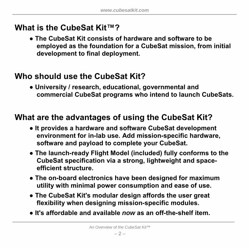
What is the CubeSat Kit�? ● The CubeSat Kit consists of hardware and software to be
employed as the foundation for a CubeSat mission, from initial development to final deployment.
Who should use the CubeSat Kit?
● University / research, educational, governmental and commercial CubeSat programs who intend to launch CubeSats.
What are the advantages of using the CubeSat Kit?
● It provides a hardware and software CubeSat development environment for in-lab use. Add mission-specific hardware, software and payload to complete your CubeSat.
● The launch-ready Flight Model (included) fully conforms to the CubeSat specification via a strong, lightweight and space-efficient structure.
● The on-board electronics have been designed for maximum utility with minimal power consumption and ease of use.
● The CubeSat Kit's modular design affords the user great flexibility when designing mission-specific modules.
● It's affordable and available now as an off-the-shelf item.

www.cubesatkit.com
An Overview of the CubeSat Kit™ � 3 �
What's included in the CubeSat Kit? ● Development Board, Salvo� multitasking RTOS software, Flight
Model (with Flight Module inside), software programming / debugging adapter, USB cable, R-B-F pin, lab power supply.
Figure 1: 1U solid-wall CubeSat Kit contents.

www.cubesatkit.com
An Overview of the CubeSat Kit™ � 4 �
What else is required to get started with a CubeSat Kit? ● A Salvo-certified compiler for TI's MSP430 ultra-low-power 16-bit RISC MCU:
● A PC for software development. ● Transceiver(s) of your choice. The CubeSat Kit accepts the
Microhard� MHX-2400 2.4GHz spread-spectrum transceiver as a drop-in option.1
● Mission-specific hardware (e.g. solar cells, antenna(e), user modules, payload).
How much does a CubeSat Kit cost? ● The 1U (10x10x10cm) CubeSat Kit as shown above is priced at
$5,000.2

www.cubesatkit.com
An Overview of the CubeSat Kit™ � 5 �
Part II
The Nitty-Gritty (Here's where it gets interesting.)

www.cubesatkit.com
An Overview of the CubeSat Kit™ � 6 �
What is the CubeSat Kit development process? ● Obtain a CubeSat Kit ☺☺☺☺ and a Salvo-certified MSP430 compiler.
Unpack the CubeSat Kit's Development Board, and get acquainted with it, the programming / debugging hardware / environment and example Salvo multitasking applications.
● Analyze your CubeSat mission-specific hardware and software requirements. Plan to run as much software (AD&C, C&DH, COM, etc.) as possible in the CubeSat Kit's Flight MCU as part of a multitasking Salvo application. Decide which available CubeSat Kit Bus� signals will be used to interface the Flight MCU to user modules. This will simplify your software effort and your hardware design. Remaining mission software will reside in other MCUs on user modules or PC/104 modules.
● Prototype mission-specific hardware on PC/104-sized user modules3 and/or off-the-shelf PC/104 modules.4
● Develop other mission-specific subsystems not included in the CubeSat Kit (e.g. payload, EPS, transceiver, antenna(e), �). Integrate RBF and launch switches into EPS.
● Integrate. Develop. Test. Debug. Iterate. Repeat as needed. ● Once your CubeSat is fully operational in the lab, move the
entire user module stack5 from the Development Board to the Flight Module. Attach solar cells and antenna(e) to the Flight Module. Program the Flight Module with the same code that's running on the Development Board. Test. Test. Test. Launch!

www.cubesatkit.com
An Overview of the CubeSat Kit™ � 7 �
Figure 2: Functional CubeSat Kit Flight Module being weighed in preparation for
vibration testing. Aluminum block between two user modules (red and green PCBs) fulfills mass model requirements. CubeSat Kit Bus connects Flight Module
(at bottom, mounted to Base Plate) to user modules. Launch switch (left near bottom corner) wired in default configuration.

www.cubesatkit.com
An Overview of the CubeSat Kit™ � 8 �
The CubeSat Kit was designed to: ● Be affordable. ● Exhibit complete conformance with CubeSat specifications. ● Maximize available user payload via a lightweight structure. ● Minimize structural and Flight Module intrusions into the
available interior volume. ● Minimize the use of wires and cables. ● Be highly user-configurable. ● Accept PC/104 modules. ● Have a standard electrical bus / module interconnect scheme.6 ● Exhibit ultra-low power consumption (<10mW operational,
<250µW sleep). ● Provide a powerful and comprehensive hardware and software
development environment. The CubeSat Kit was:
● Fully modeled in SolidWorks®. ● Brought to market after three years and several major revisions. ● Designed with input from customers and several advisors,
including some from the original CubeSat design effort.

www.cubesatkit.com
An Overview of the CubeSat Kit™ � 9 �
This was a highly challenging design exercise because: ● The existing CubeSat specification highly constrains many
aspects of the CubeSat Kit's design goals. ● Customer requirements vary wildly. ● The size of the Microhard MHX-2400 spread spectrum 2.4GHz
transceiver conflicts with the CubeSat's basic 10x10x10cm dimensions.
● The sizes of the high-current7 (10A) launch and remove-before-flight switches complicate packaging.
● The required locations of the remove-before-flight (RBF) pin, launch switch and USB connector constrain placement options and have far-reaching consequences on other components.
● A minimum of the Flight MCU's pins should be dedicated to on-board functions, leaving the rest free for the user.
● Power switching (+5V and +3.3V) and power isolation are required to achieve power targets.
● The density of components on the Flight Module dictates a 6-layer PCB.
● PCB-stacking options have ramifications for packaging density. ● Hard-anodizing (non-conductive plating) is incompatible with
the desire for the structure to provide Faraday cage isolation. ● Cost control is required keep the CubeSat Kit affordable.

www.cubesatkit.com
An Overview of the CubeSat Kit™ � 10 �
Figure 3: Semi-exploded view, skeletonized CubeSat Kit, illustrating included
components, 2.4GHz transceiver and user modules stack.

www.cubesatkit.com
An Overview of the CubeSat Kit™ � 11 �
A sheet-metal aluminum structure was chosen because: ● It's lightweight, yet strong.8 ● Manufacturing tolerances can be held to +/- 0.13mm (+/- 0.005"). ● It affords considerable freedom in conforming to CubeSat
specifications and placing internal and external components. ● It helps maximize available internal volume. ● It minimizes the use of fasteners. Inserts can be embedded in
the structure as part of the manufacturing process. The resultant structure has very low parts count.
● It promotes a modular system design. 0.5U, 1U, 1.5U, 2U and 3U CubeSats are all part of the same family.
● Aluminum structure provides Faraday-cage shielding. ● Aluminum structure can be hard-anodized (non-conductive) or
alodined (conductive) where required. ● Skeletonized and solid-wall variants can easily be
manufactured.
● However, sheet-metal manufacturing is geared towards high-volume production, and is not a cost-effective option for individual CubeSat projects. As a manufacturer, Pumpkin can pass the high-volume cost savings onto CubeSat Kit customers.

www.cubesatkit.com
An Overview of the CubeSat Kit™ � 12 �
Figure 4: Dimensional detail, skeletonized CubeSat Kit Base Plate made from
sheet-metal aluminum with stainless-steel inserts.

www.cubesatkit.com
An Overview of the CubeSat Kit™ � 13 �
Figure 5: Solid-wall and skeletonized assembled 1U CubeSat Kit Flight Models.

www.cubesatkit.com
An Overview of the CubeSat Kit™ � 14 �
Figure 6: Disassembled CubeSat Kit Flight Models.
www.cubesatkit.com
An Overview of the CubeSat Kit™ � 15 �
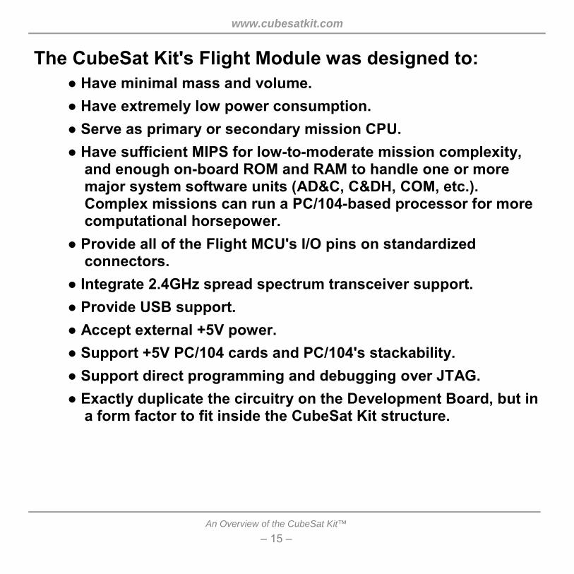
The CubeSat Kit's Flight Module was designed to: ● Have minimal mass and volume. ● Have extremely low power consumption. ● Serve as primary or secondary mission CPU. ● Have sufficient MIPS for low-to-moderate mission complexity,
and enough on-board ROM and RAM to handle one or more major system software units (AD&C, C&DH, COM, etc.). Complex missions can run a PC/104-based processor for more computational horsepower.
● Provide all of the Flight MCU's I/O pins on standardized connectors.
● Integrate 2.4GHz spread spectrum transceiver support. ● Provide USB support. ● Accept external +5V power. ● Support +5V PC/104 cards and PC/104's stackability. ● Support direct programming and debugging over JTAG. ● Exactly duplicate the circuitry on the Development Board, but in
a form factor to fit inside the CubeSat Kit structure.

www.cubesatkit.com
An Overview of the CubeSat Kit™ � 16 �
The Flight Module is based on TI's MSP430F149 MCU:
LDOOFF
VCC+5V_USB
+5V
Transceiver
2
+5V_USB
JTAG
MSP430
2
UART0UART1 VREFh/s
Reset
2
3
2
+5V_SW VCC
USB<->Serial
RS-2322
+5V_USB +5V
P1 P2 P3 P4 P5 P6 Figure 7: MSP430F149-based Flight Module block diagram.

www.cubesatkit.com
An Overview of the CubeSat Kit™ � 17 �
Additional Flight Module details: ● P6 shared between:
● USB / transceiver handshake / control interface ● Transceiver isolation ● Analog sampling channels (e.g temp sensors)
● USART1 shared between: ● Serial-to-USB converter ● 2.4GHz spread-spectrum wireless transceiver ● User (off-board on user module)
● Mixed +3.3V / +5V design: ● Level translators & buffers provide isolation, incl. unpowered states ● USB (+5V, bus-powered9) interfaces to MCU at +3.3V via isolator ● Transceiver (+5V) interfaces to MCU via isolators & level-shifters ● MCU controls –OE's on isolators & level-shifters ● MCU controls power to +5V transceiver
● Low-Power: ● Sleep at < 30µA,10 operate at < 2mA, Tx (occasionally) at > 750mA ● Powered via internal +5V or via USB

www.cubesatkit.com
An Overview of the CubeSat Kit™ � 18 �
Part III
The Results (They pleased us greatly �
hopefully they'll please you, too.)

www.cubesatkit.com
An Overview of the CubeSat Kit™ � 19 �
All design objectives were reached, including: ● Structure:
● Consists of 3 major single-piece assemblies (body, base plate, end plate) and 7 machined aluminum feet (two types � simple, and with spring plunger).
● Is alodined for electrical conductivity, except for hard-anodizing on wear surfaces and feet.
● Utilizes stainless steel fasteners throughout for uniform thermal expansion and resistance to corrosion.
● Is held together by 10 M3 screws. 9 smaller screws and 6 nuts affix feet and hold launch and remove-before-flight switches in place
● Remove-before-flight pin securing system is very strong, with audible and tactile engagement and disengagement.
● PCB stacks are assembled via 15 & 25mm M3 threaded standoffs ● System masses11, resulting in a minimum of 690g for payload, etc:
● Chassis, complete, skeletonized12 190g
● FM430 Flight Module +50g
● MHX-2400 spread spectrum 2.4GHz transceiver
+70g
● Total 310g

www.cubesatkit.com
An Overview of the CubeSat Kit™ � 20 �
● System: ● Accepts a minimum of four additional PC/104-sized user modules
(PCBs). ● Has plug-in support for MHX-2400 spread-spectrum 2.4GHz transceiver. ● Is easily expanded via Flight Module's CubeSat Bus Connectors. ● Can be powered from on-board user EPS, external +5V or USB. ● Provides multiple remove-before-flight and launch switch wiring options. ● Requires less than 8cm of high-current wiring for launch and remove-
before-flight switches. No other interconnect wiring is normally required. ● Flight Module:
● Meets all low-power requirements. ● Easy to program with complex applications (e.g. for C&DH and COM) via
Salvo multitasking RTOS. ● Only a small number of Flight Module's I/O pins have permanently
dedicated functions � the rest are free for user applications.
● Software: ● MSP430F149 with 60K instructions is well-suited to complex Salvo
multitasking applications, despite its meager 2KB RAM.

www.cubesatkit.com
An Overview of the CubeSat Kit™ � 21 �
The CubeSat Kit is a product of:
750 Naples Street San Francisco, CA 94112 USA tel: (415) 584-6360 fax: (415) 585-7948 web: http://www.cubesatkit.com/ email: [email protected]

www.cubesatkit.com
An Overview of the CubeSat Kit™ � 22 �
Thank you for your interest in the
�

www.cubesatkit.com
An Overview of the CubeSat Kit™ � 23 �
Speaker Information Dr. Kalman is Pumpkin's president and chief software architect. He entered the
embedded programming world in the mid-1980's. After co-founding a successful Silicon Valley high-tech startup, he founded Pumpkin with an emphasis on software quality. He has also been involved in a variety of other hardware and software projects.
Copyright Notice © 2003 Pumpkin, Inc. All rights reserved. Pumpkin and the Pumpkin logo, Salvo and
the Salvo logo, The RTOS that runs in tiny places, CubeSat Kit and the CubeSat Kit logo are all trademarks of Pumpkin, Inc. All other trademarks and logos are the property of their respective owners. No endorsements of or by third parties listed are implied.
All specifications subject to change without notice. 1 MHX-2400 transceiver kits are available through Pumpkin. Other transceivers can be adapted for use in the
CubeSat Kit. 2 All prices in US $. 3 CubeSat Kit prototyping boards are available � P/N 705-00301. 4 At this point, modules can be developed for ease of fabrication and testing, as there are no substantial physical
constraints on modules that are interconnected via the CubeSat Kit bus on the Development Board. 5 Prior to moving the user modules and payload to the Flight Module, you may find it necessary to redesign your
user hardware into more space-efficient format if you've prototyped many modules / functions individually. 6 Modules are interconnected via the CubeSat Kit Bus. 7 10A switches were chosen to support CubeSats of up to 3U (10x10x30cm) size, which are likely to have higher
power requirements than 1U CubeSats. 8 5052-H32 aluminum is used for the sheet-metal chassis, base plate and cover plate. 6061-T6 aluminum is used
for the CNC machined feet. 9 A bus-powered USB device is one that gets its power from the USB host (i.e. over the USB cable). 10 This is the total system sleep current, and includes the quiescent current of voltage regulators, leakage across
power-control and level-shifting FETs, etc. 11 Preliminary, subject to real-world adjustments. 12 For solid-wall chassis, add 85g.