Space Propulsion Innovation Award
33
Space Propulsion Innovation Award Oli Lane, SSTL
-
Upload
a-rocketeer -
Category
Technology
-
view
1.028 -
download
3
Transcript of Space Propulsion Innovation Award

Space Propulsion Innovation Award
Oli Lane, SSTL

Space Propulsion Innovation Award
• £10k 1st Prize: Exploratory Ideas Grant
• £7.5k 2nd Prize: Airbus DS Innovation prize
• £5k 3rd Prize: SSTL Innovation prize
Oct Nov Dec Jan Feb Mar Apr May Jun
Competition Launch Pitch presentations submitted 20-Feb-15
Judging Event 18-Mar-15
winning projects begin

Pitch Contents
• Pitch must be delivered strictly within 8 mins
• Use of examples, props and demos are encouraged (so long as it’s not dangerous)
• Pitch must cover: – Which challenge is being addressed
– What the solution is and how it addresses the challenge
– Evidence that the solution will work
– The steps to take it to flight-ready status
– What will be achieved with the prize money

Judging Criteria
• Relevance (30%): Relevance of the technology to selected challenge; degree to which this technology has the potential to be disruptive to current technology
• Technological Innovation (30%): Novelty, originality, newness to space and suitability of the work proposed, including assessment of risk and benefits;
• Benefit (20%): How quickly can this technology be implemented? How comprehensively does it solve the challenge? How big is the step from current state of the art?
• Quality of the pitch(20%): Is the pitch clear and well presented? Is
there a clear use of the prize money planned? Do the proposer(s) have the capability & track record to implement the plan?

Rules • Entrants must be based in the UK
• Winners will be announced on the day as determined by the judging panel based on the judging criteria
• Entrants can only submit one pitch per challenge, but are allowed to enter different pitches to different challenges
• Timing
– Entrants must submit pitch presentation by noon 20-Feb-15 as .pdf or .ppt file
– Entrants will be invited to pitch at the judging event before 6-Mar-15
– To win, entrants must present an 8 min pitch at the judging event held on 18-Mar-15 in London (tbc).
• Rules may be amended

Conditions • Prize money is for continuation of research • IP developed remains the property of the prize recipient • Pitch presentations should be considered public domain • 1st prize
– Requires recipients to sign a declaration, that such an award would not push them over the threshold of €200k de minimis money in 3 years (state aid rules)
– Is in the form of a 100% funded NSTP exploration grant, so a short proposal document will also be required
– 50% paid on kick-off, 50% paid on project completion – Final presentation should not contain confidential information
• 2nd & 3rd prize: – Will be awarded in the form of a purchase order from Airbus DS &
SSTL respectively in exchange for a “project report”, 100% paid up front.
– If required an NDA can be put in place surrounding the project report, but a publicly available version shall also be produced.

Challenge Discussions Today Morning Session Satellite Propulsion Components Adam Watts
• Solenoid valve for <£1k
• Low cost liquid propellant delivery
• HTP compatible valves
• Pyro Valves
• Nozzle optimisation
System Architectures Graham Viney
• Pipe joining technology
• Future landing technologies
• High dV cubesat micro-propulsion
Propulsion Tanks Bill Bentall
• 3D printed pressure vessels
• Toroidal Tank
Afternoon Session Launcher Components James McFarlane
• Advanced mechanical seal study
• Low cost launcher engine
• Turbopumps
• Ceramic rocket chamber to metal expansion cone bonding/joining
Measurement Steve Clark
• High temperature measurement in remote confined spaces
• Direct measurement of EP thrusters
Xenon Management Jon Huddleson
• Xenon reclamation
• Xenon mass flow measurement
• Xenon mass flow rate control at very low flow rates

Propulsion Challenges 2014
Satellite Propulsion Components

Solenoid Valve for <£1000 Context
• Space qualified valves are the dominant cost in a low cost propulsion system. Can an existing valve from another industry be used?
Requirements
• Open 28V / Hold 5V
• Mass < 300g
• Volume < 20x20x150mm
• Cycles > 105
• Vibration: >20gRMS
• Leak rate < 1x10⁻⁶ sccm He
• Butane, Xe & other inert gas compatible

Low cost liquid propellant delivery Context
• Liquid propellants (e.g. HTP, Water) need to be delivered reliably to
the tank exit port in Zero-g. Traditional propellant tanks are made
with custom Ti forgings and an EPDM rubber diaphragm & are very
expensive
Requirements
• Vibration: 20gRMS
• Capacity: 8 litres
• Propellant flow rate: 0.2 to 1.0g/s (constant)
• Delivery pressure >5bar
• Compatibility: HTP, Hydrazine, water
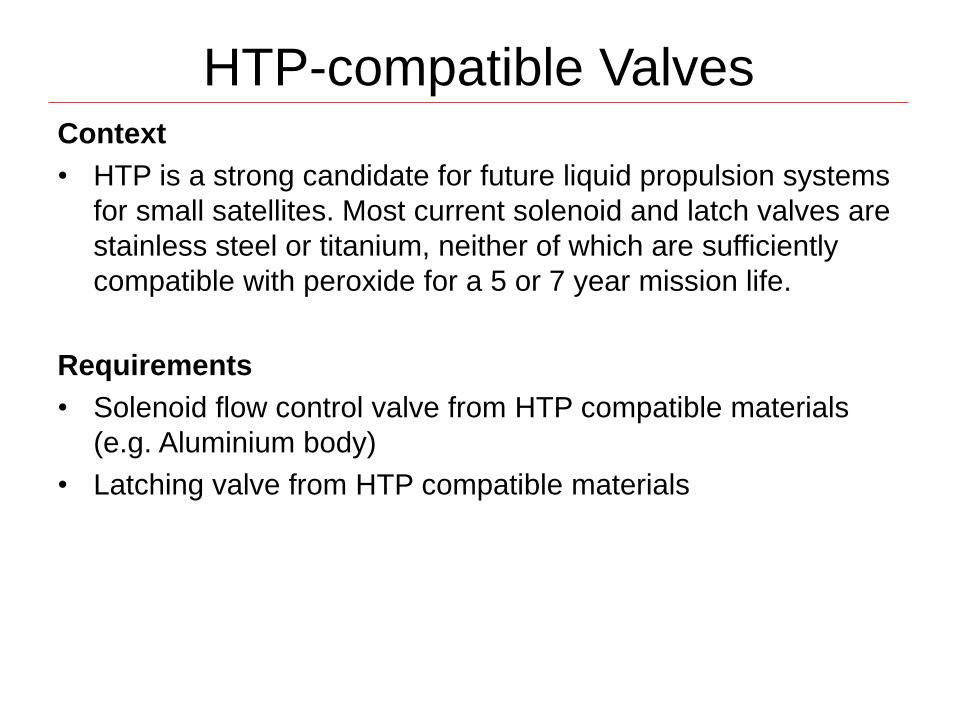
HTP-compatible Valves Context
• HTP is a strong candidate for future liquid propulsion systems
for small satellites. Most current solenoid and latch valves are
stainless steel or titanium, neither of which are sufficiently
compatible with peroxide for a 5 or 7 year mission life.
Requirements
• Solenoid flow control valve from HTP compatible materials
(e.g. Aluminium body)
• Latching valve from HTP compatible materials

Pyro Valve Replacement Context
• Pyro valves are explosive valves that are used in spacecraft propulsion systems to permanently
change the state of that valve (i.e permanently open the valve or permanently close the valve).
They are used in different locations in the propulsion system for different roles. For example:
• For a geostationary telecommunications satellite utilising a bi-propellant apogee engine with a
regulated propellant pressurant feed system, pyro valves are used to permanently lock off the
apogee engine once all apogee engine firings have been completed. This is achieved by installing
normally open pyro valves just upstream of the apogee engine on both the fuel and oxidiser
propellant feed lines. These valves are open when the apogee engine is being used during the
transfer process. The pyro valves are then fired to close them to permanently isolate off the
apogee engine from the rest of the propellant system therefore ensuring propellant cannot leak
out of any of the apogee engine valves or fittings.
• Pyro valves are welded into the propulsion system. The issue with pyro valves are that when fired,
the energy generated by the explosive charge can cause cracks to form in the welds. Through
these cracks propellant can leak out causing the satellite to fail.
Requirements
• An alternative to a pyro valve must be such that:
1. It does not require any power to maintain the valve in the open or closed position
2. Once permanently closed there is no chance that there can be leakage across the closed valve
3. The method of actuating the valve does not risk damage to the propulsion system such that it can cause
the propulsion system to fail

Nozzle Optimisation Context
• Space constraints for ‘apogee’ engines to fit within a bounding cylindrical envelope also place a constraint on the engines efficiency. The expansion section of the De Laval nozzle plays a major role in determining the engine overall efficiency. The major parameters are the supersonic area ratio and contour shape. A conical shaped nozzle is the most basic shape of nozzle that can be specified given a bounding envelope. Most apogee engines use a more ‘rounded’ contour that ‘turns’ the flow, reduces ‘divergence’ at the exit and therefore operates more efficiently than a conical shape.
• The High Thrust Apogee Engine (HTAE) is an 1100N in-space engine being designed by Moog ISP to support the European Space Agency’s future planetary exploration missions, such as Mars sample return.
• The expansion nozzle design presently baselined for the first engineering model (see below) derives from a heritage LEROS apogee engine, which makes the HTAE expansion nozzle quite large. A large expansion nozzle results in low engine natural frequency and problems with engine accommodation in the spacecraft and/or available launch adaptors. There is a desire to reduce the size of the expansion nozzle whilst maintaining a high nozzle thrust coefficient.
Requirement
• The objective of this project is to generate a feasible nozzle design that is smaller than the presently baselined design and has comparable (or better) predicted performance.
Minimise length
Upperbound length
Up
pe
rbo
un
d d
iam
ete
r

Propulsion Challenges 2014
System Architectures

Pipe Joining Technology Context
• Either a new physical principle to join metal pipes or a better way of producing very robust
(probably welded) leak tight seal for use on high pressure or aggressive liquid systems for space
use.
Requirements
• To join together Titanium alloy, Stainless Steel or aluminium alloy tubes from 1/8 “ to 1/2“ outer
diameter
– It would be most useful if the technique can be used to join the different materials to one another (eg
Stainless steel to Ti alloy or Ti alloy to Aluminium for example)
• Ideally to be used to integrate complex pipe assemblies
• High pressure systems to 310 bar operating pressure / Low Pressure systems to 24 bar op
• Joining process ideally has to be free from high levels of electromagnetic radiation that might
damage spacecraft equipment.
• Finished assembly has to
– Be compatible with corrosive fluids (Hydrazine/ Peroxide/Oxides of Nitrogen)
– Be helium leak tight to 1E-06 scc helium/s (ideally although some latitude here)
– Withstand -40 to + 100 deg C thermal environment
– Withstang 50 g(rms) mechanical
– be produced free of contamination (or be able to be precision cleaned of particulate and non-volatiles -
greases hydrocarbons etc)
– be verifiable by some means (typically x-ray)
– be performed (eventually) in confined spaces although this may not be necessary for tech demo
• Dead volume has to minimised
• Airbus will be able to perform any verification testing if the developer does not have facilities but
compatibility will be assessed by review of design rather than testing at this stage.

Future Landing Technologies Context
• Future planetary landing missions will potentially employ larger and heavier payloads and with little potential for improved launcher performance in the near future, means that any payload increase must come from more efficient propulsion systems for interplanetary transfer stages and planetary landers.
• Whilst it could be envisaged that higher performance propulsion systems could be used for transfer stages (i.e. electric propulsion or larger chemical engines), the usage of these systems for planetary landers is unrealistic due to the requirements for high braking delta-V's / short burn times combined with volume constraints on the planetary lander design.
• To this end the challenge is to present ideas for future propulsion technologies for both kinds of lander scenarios - either zero-atmosphere/Pure thrust delta-V as for a lunar lander or partial rocket delta-v landing such as for a Mars lander.
Requirements
• The technologies that can be proposed can be for any system that can meet the landing requirements, with the following restrictions:
– Performance has to be better or equal to the current state of the art
– Density impulse has to be better or equal than the current state of the art
– Use of in-situ resources ie Martian atmosphere is encouraged.
– Compatibility with existing propulsion systems feed systems is seen as an advantage

High Delta V CubeSat Micro-Propulsion
Context
• CubeSats might not be released into orbits that are ideal for the
mission or station-keeping may be needed. Thus, some flexibility in
on- board velocity management is required
Requirement
• Total Impulse: 1kNs
• System: low mass, low cost, safe & clean
• Pre-packaged green propellant, clean exhaust
• Energy drain at EOL

Propulsion Challenges 2014
Propulsion Tanks

3D printed pressure vessels Context
• With the advent of Additive Layer Manufacturing techniques serious consideration is being given to "printing" of propulsion components for spacecraft.
• In particular, printed propellant and pressure vessels have the potential to reduce costs, manufacturing times and allow for seamless integration of Propellant Management Devices (PMD) for propellant tanks.
• However such factors such as propellant compatibility, surface finish, tank integration to spacecraft structure, minimal propellant residuals, zero-g expulsion amongst others leads to the need for careful assessment of ALM manufacturing techniques and processes.
Requirements
• The challenge is to design and develop a propellant tank with an integrated PMD that can perform as well as current spacecraft propellant tank designs but with the potential for reduced production cost and/or production time as well as simplified manufacturing process (i.e. reduction of welds).

Toroidal Tank Context
• Toroidal tanks have the potential to improve the propellant packaging on planetary landers/solar system probes. Current designs for tanks are spherical/cylindrical which usually means increased spacecraft/transfer stage height. For planetary landers and interplanetary stages , the goal is to improve the Centre of Gravity control of the stage as well as reducing the overall stack height by employing toroidal tanks.
Requirements
• Containment of propellants/gas at high pressures
• Propellant compatibility
• Expulsion of propellants with a minimum propellant residual
• Design and manufacturing of Propellant Management Devices (PMD's)
• Mounting/interfaces with space vehicles
• Guarantee of bubble free propellant delivery.
The challenge is to design a tank that could be carried forward to manufacture / test

Challenge Discussions Today
Morning Session
Satellite Propulsion Components Adam
Watts
• Solenoid valve for <£1k
• Low cost liquid propellant delivery
• HTP compatible valves
• Pyro Valves
• Nozzle optimisation
System Architectures Graham Viney
• Pipe joining technology
• Future landing technologies
• High dV cubesat micro-propulsion
Propulsion Tanks Bill Bentall
• 3D printed pressure vessels
• Toroidal Tank
Afternoon Session
Launcher Components James McFarlane
• Advanced mechanical seal study
• Low cost launcher engine
• Turbopumps
• Ceramic rocket chamber to metal
expansion cone bonding/joining
Measurement Steve Clark
• High temperature measurement in
remote confined spaces
• Direct measurement of EP thrusters
Xenon Management Jon Huddleson
• Xenon reclamation
• Xenon mass flow measurement
• Xenon mass flow rate control at very
low flow rates

Propulsion Challenges 2014
Launcher Components

Advanced Mechanical Seal Study
Context • The SABRE air-breathing rocket engine uses several items of rotating machinery all of which need efficient and long-
lasting mechanical seals. Traditionally turbo-pump seals for liquid rocket engines have used balanced graphite based mechanical seals (spring loaded, piston or bellows type or a combination of all three) which have a short operational life due to the high rotational velocities and differential pressures encountered at the seal interface which leads to high seal wear rates and low life.
• For a re-useable system like the SABRE engine it is desirable to increase the lifetime of such seals in order to reduce the engine service time between flights. One possible way to do this is to introduce an actively controlled seal which can sense and control the gap between the rotating shaft and the mechanical seal face.
• One suggested way of doing this is to use a piezo-electric actuator which can be driven by electrical signals to control the gap as required. By actively controlling the gap between the rotating and static face to within a few microns the leak rate from the mechanical seal can be reduced without suffering large wear rates due to the lack of contact between the two faces. The system could also be used to accommodate thermal contraction / expansions encountered within the device.
• A method is required to measure the seal gap in order to provide the positive feedback for the actuator (suggestions: Use seal running temperature or overall leak rate), and development of a compact, efficient seal /actuator design
• Such a system if successfully developed could find applications in rocket engine turbo-pumps and any other type of rotating machinery requiring a mechanical seal.
Requirements
• Fluid: Gaseous Helium (Cryogenic)
• Maximum Differential Pressure: 50 bar
• Shaft Diameter ~40mm
• Shaft Rotational Speed: 45,000 RPM
• Required Maximum Leak Rate: 1 g / minute
• Minimum Lifetime: 200 flights x 694 seconds ~ 38.5 hours
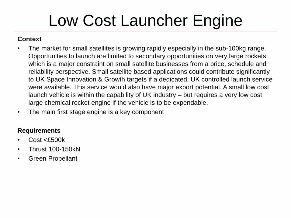
Low Cost Launcher Engine Context
• The market for small satellites is growing rapidly especially in the sub-100kg range.
Opportunities to launch are limited to secondary opportunities on very large rockets
which is a major constraint on small satellite businesses from a price, schedule and
reliability perspective. Small satellite based applications could contribute significantly
to UK Space Innovation & Growth targets if a dedicated, UK controlled launch service
were available. This service would also have major export potential. A small low cost
launch vehicle is within the capability of UK industry – but requires a very low cost
large chemical rocket engine if the vehicle is to be expendable.
• The main first stage engine is a key component
Requirements
• Cost <£500k
• Thrust 100-150kN
• Green Propellant

Turbo-pumps Context
• The market for small satellites is growing rapidly especially in the sub-100kg range. Opportunities to launch are limited to secondary opportunities on very large rockets which is a major constraint on small satellite businesses from a price, schedule and reliability perspective. Small satellite based applications could contribute significantly to UK Space Innovation & Growth targets if a dedicated, UK controlled launch service were available. This service would also have major export potential. A small low cost launch vehicle is within the capability of UK industry – but requires a very low cost large chemical rocket engine if the vehicle is to be expendable.
• A turbopump to pressurise this engine is a critical enabling technology, enabling the engine to operate efficiently within the atmosphere, and offering a greatly reduced dry mass fraction. However turbopumps have historically increased the cost of simple pressure fed rocket engines by a large factor, 10-50x. So a low cost rocket turbopump remains a significant challenge for small satellite launch.
Requirements
• Flow rate: 10-30kg/s (equivalent to a thrust of 35-70kN)
• Head (deltaP) @ max flow rate: 3MPa
• Mass : not more than 50kg
• Power source: To Be Determined, however novel approaches (e.g. electric power
sources, avoiding the use of a turbine drive) are desirable
• Suitable for Cryogenic liquid oxygen & other oxidising propellants, and liquid hydrocarbons (methane, propane, kerosene)
Further useful info
• Recent UKLaunch event provides further information on the background to this challenge: http://sec.kingston.ac.uk/uklaunch
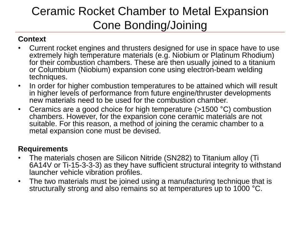
Ceramic Rocket Chamber to Metal Expansion
Cone Bonding/Joining Context
• Current rocket engines and thrusters designed for use in space have to use extremely high temperature materials (e.g. Niobium or Platinum Rhodium) for their combustion chambers. These are then usually joined to a titanium or Columbium (Niobium) expansion cone using electron-beam welding techniques.
• In order for higher combustion temperatures to be attained which will result in higher levels of performance from future engine/thruster developments new materials need to be used for the combustion chamber.
• Ceramics are a good choice for high temperature (>1500 °C) combustion chambers. However, for the expansion cone ceramic materials are not suitable. For this reason, a method of joining the ceramic chamber to a metal expansion cone must be devised.
Requirements
• The materials chosen are Silicon Nitride (SN282) to Titanium alloy (Ti 6A14V or Ti-15-3-3-3) as they have sufficient structural integrity to withstand launcher vehicle vibration profiles.
• The two materials must be joined using a manufacturing technique that is structurally strong and also remains so at temperatures up to 1000 °C.

Propulsion Challenges 2014
Measurement

High temperature measurement in
remote, confined spaces Context
• Ion thruster engines are currently developing for use in space applications. Due to the nature
of the technology, the hardware is extremely complicated, and can experience large thermal
gradients; accurate knowledge of all temperatures within the engine is needed
• Extensive thermal analysis has been performed, but temperatures to validate this modelling
is limited by the use of conventional sensors in a vacuum environment (i.e. thermocouples or
thermistors). They cannot be easily accommodated on the extremely small components and
do cause problems with the high current & voltage power supplies used.
Requirements
• Ideally a temperature measurement technique with the following attributes is required:-
• Can be easily accommodated on extremely small components situated deep inside the
engine structure, preferably without the need for feeding wiring to the external environment.
• Can operate over temperature ranges of -180˚C to + 1500 ˚C
• Can operate within a vacuum environment.
• Can be used on components which have large currents passing through them.
• Can monitor temperatures in real time; i.e. during extreme transient changes.
• Is not dependent on the emissivity of the surface finish, since it is possible that this changes
throughout the temperature range experienced within the engine.
• Since the engines can only be operated within a vacuum, it is also necessary to either store
the transient data or to somehow transfer it from inside the vacuum chamber to the external
environment.

Direct thrust measurement of Electric
Propulsion Thrusters Context
• Today’s Electric Propulsion thrusters produce anywhere between 1mN and 300mN of thrust, which need to be verified at accuracies at one or two orders of magnitude lower. They can only be operated under vacuum.
• There are many examples of EP thrust balances that work perfectly in a laboratory on a seismic block but performance is dramatically reduced when used in a real vacuum facility with a real thruster.
Requirements
• The challenges with thrust balance are considered to be:
a. How to transfer the propellant mass and electrical power across the fixed/moving part of the balance without influencing the thrust measurements?
b. Resilience to mechanical (vacuum pumps vibration) and thermal conditions (heaters and cryogenic surfaces) prevalent in a vacuum facility.
c. Ability to perform relatively high frequency thrust measurements (~2kHz), not possible with current pendulum type balances.
d. Resilience to thruster induced phenomena e.g. strong magnetic fields, facility target sputter (long term), thruster induced thermal gradients, plasma interactions.
e. In-situ calibration – how can this be reliably achieved (ideally using a different physical process to the one employed by the balance).

Propulsion Challenges 2014
Xenon Management

Xenon Reclamation Context
• Spacecraft Electric Propulsion systems typically uses Xenon gas as a propellant. This is a relatively expensive gas. During the course of tests, operating the thrusters in vacuum chambers, the Xenon expelled into the chamber is condensed out of the vacuum environment via the use of very low temperature cold panels in order to sustain the required vacuum level. At the end of testing, the gases that were condensed onto the cold panels are allowed to boil off, and then lost to atmosphere.
Requirements
• Method of recovering the xenon in a cost effective manner so that it may;
– Either, be sold back to the supplier in order to recover cost; or
– if high enough purity can be achieved, enable direct reuse for further tests. Required xenon purity is typically Xe 4.5 or above (>99.995% pure)

Xenon Mass Flow Measurement Context
• Spacecraft Electric Propulsion systems typically consume Xenon gas at a rate of 1 to 10mg/s – it is the mass flowrate that is critical as opposed to volumetric flowrate.
• Typical devices used are based upon sensing thermal changes between inline resistive coils as a consequence of the gas passing through. This is however very sensitive to changes in the local thermal environment (temperature levels and gradients across the device).
Requirements
• Novel, alternative methods of measuring low mass flowrates of gases are sought. Key requirements being,
– Space flight compatible (materials), low mass, low cost.
– hermetically sealed,
– repeatable and reliable
– temperature and lifetime stability
• Other gases used during ground testing verification are, Helium (for leakage), Argon and Dry Nitrogen.

Xenon mass flow rate control at very low
flow rates. Context
• Spacecraft Electric Propulsion systems typically consume Xenon gas at a
rate of 1 to 10mg/s – it is the mass flow rate that is critical as opposed to
volumetric flow rate.
• In some applications it is necessary to vary the flow rates for different thrust
levels.
• Solutions to date can be either bulky and expensive, or sensitive to local
temperatures variations and gradients.
Requirements
• Novel, alternative methods of varying low levels of mass flowrates of gases
are sought. Key requirements being,
– Space flight compatible (materials & processes), low mass, low cost.
– Low mass flow at low pressure (<1bar absolute),
– hermetically sealed,
– minimal to zero hysteresis to enable open-loop control against look-up table
– repeatable and reliable
– temperature and lifetime stability