Soundscape V6.2 User Guide - Solid State Logic
242
www.solidstatelogic.com Soundscape. This is SSL. Soundscape V6.2 User Guide
Transcript of Soundscape V6.2 User Guide - Solid State Logic

www.solidstatelogic.com
Soundscape. This is SSL.
Soundscape V6.2User Guide

Document HistoryApril 2012 82BSSP01A 6.2 Initial Release

Table of Contents
TTaabbllee ooff CCoonntteennttss iiiiii
11.. IInnttrroodduuccttiioonn 11Safety and Installation Considerations 1
How to use this manual 2Reading conventions 2
Website 3
SSL Soundscape - The SSL DAW 4High Performance SSL Audio Engine 4Advanced and collaborative Editing 4Digital mixing, effects and processing 4DSP-based Hardware Processing 4Native effects and DSP processing plug-ins 4
22.. SSSSLL SSoouunnddssccaappee VV66 SSooffttwwaarree IInnssttaallllaattiioonn 55Important Preparations 5
Compatible SSL Audio Cards 6System Requirements 6System Recommendations 7
Installing from Web Download 8Main Installation Procedure 8
Installing DSP and VST Plug-Ins 10
33.. SSoouunnddssccaappee QQuuiicckk SSttaarrtt GGuuiiddee 1111SSL Mixer or SSL Soundscape? 11
SSL Mixer 11SSL Soundscape 11SSL Soundscape and SSL Mixer together 11
Unit Configurator 12
Basic Configuration 13Clock Synchronisation 13I/O Mode 14Timecode Synchronisation 15Authorising the Soundscape Software and Modules 15
Opening an Existing Mixer and Arrangement 16
Creating your first Soundscape Project 17Recording Audio 17Recording Automation 20
Mixing, VST Buffers and ADC 22
44.. SSoouunnddssccaappee OOppeerraattiioonnss 2233Main Screen Overview 23
Docking Arrange and File Manager Windows to the Main Window. 23Toolbar 24
Tool selection 24Tooltips 24
Status Bar 25Mouse position 25Snap 27Sync In 28Sample Rate 28
Soundscape Owner’s Manual Page iii
Frame Rate 28Record Format 29Master Clock 29L<−>R Readout 29
Arrange Window 30Creating and Opening Arrangements 30Appending Arrangements 31Saving Arrangements 31Record Tracks 32Recording Audio 33Auto Punch In/Out 35Loop Recording and Loop Stacks 36Pre and Post Roll, Auto Stop 36Recording while Slaving to external Timecode 37Arrangement Navigation 38Arrangement Parts 40Locators and Markers 41Tape Transport Bar 44Editing Tools 47
Mix Window 75Creating, Loading and Saving Mixes 75Mixer Editing Tools 76Structuring the Mix Window 77Basic Mixer Strip Structure 80Basic Controls 81Scribble Strips 83DSP Resources and DSP Auto Routing 83Mixer Views 85Input/Output Identification 87Basic I/O and Routing Elements 89Mixer Strip Input/Output Configurations 92Understanding the Signal Path 101Standard DSP Mixer Plug-Ins 102Audio Toolbox plug-ins 108Using VST Plug-Ins 112Automatic Delay Compensation (ADC) 115
Mixer Automation 118Enabling Automation 118Automation recording 118Automation Setup window 121Automation concepts and Mixer Control behaviour 122Mixer Control response to automation data 122Automation editing 124Mixer editing with existing Automation 127
Console Control 128Introduction 128Feature Overview 128Activating and Configuring SSL Console Control 129V-Pot Operation 130Parameter Group Details 131Modifier Keys 139Mixer Channel Navigation 139Channel Strip Controls 140Displays 141Function Keys 141
Page iv Soundscape Owner’s Manual
Automation Control 141General File/Edit Commands 141Timeline/Transport Control 142Markers 142Cursor Keys 142Jog Wheel 143Foot Switch Control 143MCU (Mackie Control Universal) command Mapping to Soundscape commands144Legacy Console Manager 147
File Manager 151Overview and Navigation 151File and Folder Operations 153Auditioning Files and Arrangements 157Opening and Dragging Files into the Arrange Window 158
Project Conversion 159Introduction 159Opening Third-Party Projects 161Quick-Saving in Third-Party Project Formats 161Full Pro-Convert Window 162Project Tab 162Conversion Tab 163Project Format Reference 167
Video File Player Window 168Video System Setup 168Video Settings 169
9-Pin Window (Soundscape 32 Systems only) 170Overview 1709-Pin Modes 170Preparation: Modifying the .INI file for 9-Pin operation 173
Big Current Time Window 174
Audio Buffer Activity Window 175
55.. MMeennuu RReeffeerreennccee 117777File Menu 177
Arrangements 177Mixers 180XPro Import/Export 182Video Files 191Tempo Maps 192Search File... 192Exit 192
Tape Menu 193
Edit Menu 194Undo/Redo 194Editing tools 194Mixer, Automation and Automatic Delay Compensation 194Zoom and Scroll 194
Global Menu 195
Settings Menu 201Record Format 201Master Clock 202W/S Clock Out 204I/O mode 205Synchronisation 206
Soundscape Owner’s Manual Page v
Legacy Soundscape 32 Synchronisation 206Sample Rate 208Varispeed 208Time Code Format 209Time Axis 209Waveform Axis 209Snap 209Sync Setup 209Legacy Soundscape 32 Sync Options 210Record/Playback Setup 211Automation Setup 212Preferences 212Various Settings 222
Options Menu 225
View Menu 226Overview 226Grid 226Dock Arrange window & File Manager 226
Help Menu 227User Guides 227Read Me notes 227About SSL Soundscape 227
66.. SSoouunnddssccaappee KKeeyybbooaarrdd SShhoorrttccuuttss 222288
77.. SSuuppppoorrtt 223311Support, FAQs and Online Help Centre 231
IInnddeexx 223333
Page vi Soundscape Owner’s Manual

Soundscape Owner’s Manual Page 1
1. Introduction
Welcome to SSL Soundscape V6, the High Performance DAW from SSL and the perfect companion for your SSL MX4 orMadiXtreme audio card. Ultra reliable 128 channel simultaneous recording/playback, SSL plug-ins, 128 channel MADI I/O andadvanced DAW editing and workflow paired with the pristine audio quality you expect from any SSL product.
Should you ever need assistance in setting up or using your sound card, Solid State Logic’s website contains extensive FAQsection: http://www.solid-state-logic.com/support/io.asp
Please register your SSL audio card and Soundscape Software on our website. This will ensure that you receivenotifications of future software and driver upgrades and other important information, and that your guarantee isregistered. Registration will also make you eligible for technical support. Visit us at: www.solidstatelogic.com
Solid State Logic is committed to the development and marketing of professional solutions for native PC and Mac baseddigital audio recording systems.
The Soundscape DAW and MX4/Mixpander cards, used in combination with our XLogic Alpha-Link audio converter products,provide a flexible, professional quality, high channel count audio solution for PC based audio recording, editing and mixing.
SAFETY AND INSTALLATION CONSIDERATIONSGeneral Safety• Read these instructions.• Keep these instructions.• Heed all warnings.• Follow all instructions.• Do not use this apparatus near water.• Do not expose this apparatus to rain or moisture.• Do not block any ventilation openings. Install in
accordance with the manufacturer’s instructions.• Do not install near any heat sources such as radiators,
heat registers, stoves or other apparatus (includingamplifiers) that produce heat.
• There are no user-adjustments, or user-serviceableitems, on this apparatus.
• Adjustments or alterations to this apparatus may affectthe performance such that safety and/or internationalcompliance standards may no longer be met.
Caution• To reduce the risk of electric shock, do not perform any
servicing other than that contained in these InstallationInstructions unless you are qualified to do so. Refer allservicing to qualified service personnel.
Installation Notes• When installing this apparatus, place the host system
into which it is to be installed on a secure level surface.• To prevent damage from static electricity when
installing this apparatus, either to the host system or tothis apparatus, always take proper anti-staticprecautions. Always use an anti-static wristband. If indoubt, please refer to qualified service personnel.
• Take care of rough or sharp edges when accessing theinside of the host system.
• Never install or remove this apparatus whilst the hostsystem is powered. Always remove the power cordfrom the host system prior to accessing this apparatus.
• If in doubt about installing this apparatus, please referto qualified service personnel.

Page 2 Soundscape Owner’s Manual
HOW TO USE THIS MANUALThe SSL product range has been designed from the ground up to be easy to use. If you are familiar withthe Windows environment, installing PCIe, and PCI cards and the basics of recording and playing backdigital audio, you could probably just set the system up and feel comfortable running a session withinan hour.
However, SSL Soundscape offers a wealth of powerful and helpful features that you will only discoverquickly by reading this manual. It is therefore advisable, at some point, to read it from cover to cover.For example, Soundscape offers a wealth of precise Audio Editing Tools and the Mixer is fullyconfigurable, and while you may find it simple to edit your recordings with simple tools you are familiarwith from other DAW‘s and a few ready-made Mixers initially serve your needs, to really harness thepower of Soundscape, read Chapter 4 of this manual as soon as you can.
Please make sure you understand the Master Clock and Sample Rate concepts and that you understand the software’shardware settings. It is also a good idea to have the system switched on while you read the manual, so that you canexperiment with the features you read about.
We trust that you will soon feel confident creating and using your own Projects. However, even when it has become secondnature, the comprehensive Table of Contents (located at the beginning) and the search function in your PDF reader softwarewill provide convenient ways to check specific information whenever you need it.�
Reading conventionsDesignation of supported hardwareSoundscape V6 software supports the MX4, MadiXtreme and Mixpander audio cards. The functionality of these cards issimilar although their specifications vary. The information in this manual relates to both cards. Differences are pointed outwhere necessary.
Legacy Soundscape Systems (eg. the Soundscape 32 System) can be used in a limited way with Soundscape V6 as a:〮〮MIDI Sync Device (MTC, MIDI Clock) or as Time Code Sync and 9 Pin (requires Sync Option), connected to a PCI Host IF Card〮As an I/O Device when connected to a Mixpander card
However, the Soundscape User Guide does not go into too much detail about installation and configuration of legacySoundscape systems. Please read the Soundscape Editor V5.5 manual as well, when you plan to integrate a legacy SS system.
Key commands and key combinations Some Soundscape functions can be accessed through the use of computer keyboard keys or key combinations, as well asby using a mouse or other input device. In this manual computer keys will be shown between square brackets. For example,the key for the letter ‘E’ will be written: [E]. Key combinations will be written using ‘+’ signs. For example, pressing the ‘D’ keywhile holding the ‘Control’ key will be written as [Ctrl]+[D].
MenusWhere appropriate, to indicate a ‘path’ under one of the main menus, the following format will be used:
Menu: Header / Submenu 1 / Submenu 2 / Submenu3 / Item.
ScreenshotsThe appearance of the Soundscape software on your computer screen may be different from the screenshots in this manual.
LabellingAs a general rule, bold type indicates that the text precisely reflects on-screen labelling.
Internal ReferencesPage references to elsewhere in this User Guide are displayed in italics. ‘Single quotation marks’ are used when the text isalready in italics. Internal references are also hyperlinked – clicking on them will navigate your pdf reader to that page.
If possible, pleasedo not print thismanual.
Soundscape Owner’s Manual Page 3
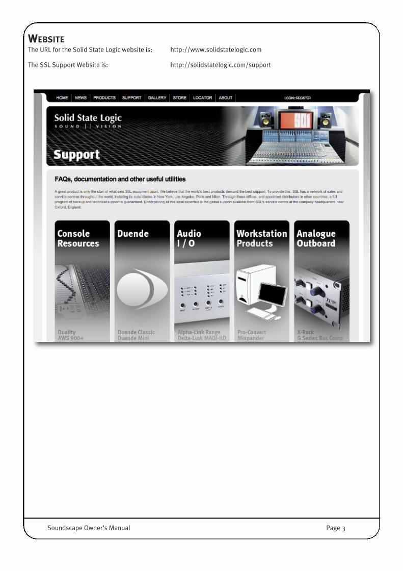
WEBSITEThe URL for the Solid State Logic website is: http://www.solidstatelogic.com
The SSL Support Website is: http://solidstatelogic.com/support
Page 4 Soundscape Owner’s Manual
SSL SOUNDSCAPE - THE SSL DAWHigh Performance SSL Audio EngineSSL Soundscape is powered by SSL’s MX4 technology, built from the legendary Soundscape DAW’s heritage. The completelyre-engineered Soundscape is reborn to be blazingly fast, ultra-reliable and completely optimised for modern Multi-CoreProcessor Architectures and Windows 7 (32 Bit or 64 Bit).
The brand new Soundscape Hybrid Core Audio Engine allows recording, editing, overdubbing and mixing of 128 Tracks on astunningly relaxed PC, with many hundreds of zero latency DSP and native VST Plug-Ins. Unlike any other DAW Software onthe market, Mixing and Monitoring can happen with DSP FX completely ‘in the box’ with superior pristine SSL Console GradeSound Quality and with almost no latency (4 samples ‘roundtrip’).
Advanced and collaborative EditingSophisticated editing tools and workflow strategies, extreme speed and performance and a clean and intuitive workspace forAudio Pros. Soundscape is made for speed and to keep the user in a creative flow.
SSL Soundscape uses standard local or networked Windows storage to record and playback uncompressed 16 Bit and 24 BitSoundscape Takes, Wave and Broadcast Wave Files. A Soundscape Project can also contain a mixture of file-formats and bit-depths avoiding the need for awkward file conversions. For collaborative projects, there’s no need to copy files to colleagues’computers, Soundscape allows safe collaboration over a standard Gigabit Ethernet Network.
Digital mixing, effects and processingThe SSL ‘Console’ inside the Soundscape software runs on the on-board DSP-powered mixing engine providing immenseaudio processing capabilities. The Mixer’s architecture is amazingly flexible and puts no limits on the way the channels arestructured.
The SSL Console EQ-Filters, Channel Dynamics, and the legendary Bus Compressor plug-ins offer the highest qualityprocessing you can find in digital audio and provide console grade processing for that 'hit record' sound.
The SSL Audio Toolbox provides essential building blocks, with multi-function dynamics processors (gate, expansion,compression, and limiting), delay based effects (multitap delay, chorus, flanger) and dither. Optional effects and processingplug-ins are also available from other world renowned developers.
DSP-based Hardware ProcessingPC-based mixers suffer from a certain amount of processing delay, also known as ‘latency’. This may be very small on anexpertly configured, modern PC, but gets worse as native effects and processors are added into the signal path, so much soit can be impossible to play an instrument and monitor the output in real-time through a software mixer with a few plug-ins.This is why most native MIDI+Audio sequencers now include direct Monitoring (without FX) and a ‘plug-in delay compensation’feature, which only solves the problem in mixing situations, but is, by its very nature, unusable while recording, tracking andmonitoring.
In contrast, the DSP-powered plug-ins offer a level of performance on a par with high-end audio hardware in terms of soundquality and comparable to a hardware mixing console in terms of latency (…or absence thereof!). This is a major advantagewhen recording live vocals or instruments. DSP effect plug-ins can be inserted at any point in the signal path and the wet signalcan be monitored in real-time (i.e. without any annoying processing delay) while recording the dry or wet signal, or both.
Native effects and DSP processing plug-insWhile SSL format DSP-powered effects and processing plug-ins provide a unique combination of superior sonic quality,negligible latency and rock-solid reliability, we appreciate that native processing has a part to play. Soundscape supports theVST format, running on the host CPU, and VST FX Plug-Ins can be inserted directly in the SSL Mixer, seamlessly, including fullsupport of dynamic automation of all knobs. This is useful in situations where latency is not an issue (e.g., during mixing andmastering) and allows access to hundreds (if not thousands) of plug-ins.
Note that MadiXtreme cards have no on-board processing. The features mentioned above, therefore, do not apply.

Soundscape Owner’s Manual Page 5
2. SSL Soundscape V6 Software Installation
IMPORTANT PREPARATIONS
Before you proceed installing Soundscape, please ensure that you have successfully completed the HardwareInstallation, as described in the MX4 Installation Manual, otherwise you will not be able to successfully install or workwith the Soundscape or Mixer application.
The files required for the following Installation can either be found on the CD which came with your audio card (SSL MX4,MadiXtreme 64, or MadiExtreme 128) or can be downloaded from the SSL website.
The audio card CD comes with an Install Menu Application (MX4_start.exe, for example), which allows easy Installation of allsoftware components.
In order to avoid any complications during software installation please follow these steps in the order indicated:
1 Make sure you have installed the audio card and its drivers properly. If you have an internet connection, please downloadand use the most recent version, available from the SSL website.
2 Run the Soundscape V6.2 Combo Installer and as well as any optional extras – Pro-Convert V6 for Soundscape and SSLConsole Control for Soundscape.
3 Start the SSL Soundscape V6.2 Software and follow the Instructions of the Unit Configurator. Make sure the Software runsproperly.
4 Enter the Mix Password you find on your audio card Registration card, under Options / Passwords / V2.xx Mixer startingwith the letter M.
Note that the MX4 comes with plug-in passwords. If you have no plug-ins to install, please ignore instructions 5 to 8below:
5 Enter the SSL Console EQ Password you find on your audio card’s registration card (SEQ), under Options / Passwords /SSL Console EQ starting with the letter M.
6 Enter the SSL Console Dynamics Password you find on your audio card’s registration card (SCD), under Options /Passwords / SSL Console Dynamics starting with the letter M.
7 Enter the SSL Bus Compressor Password you find on your audio card’s registration card (SBC), under Options / Passwords/ SSL Console Bus Compressor starting with the letter M.
8 Enter the SSL Audio Toolbox Password you find on your audio card’s registration card (ATB), under Options / Passwords/ Audio Toolbox (Partx) starting with the letter M. You only have to enter the password once.
9 Enter the SSL Soundscape V6 Password you find on your Soundscape V6 webshop receipt or in your ‘MySSL’ accountonline (SS6), under Options / Passwords / Soundscape Version 6 starting with the letter M.
10 Enter the Time Module Password you find on your Soundscape V6.2 webshop receipt or in your ‘MySSL’ account online(XTM), under Options / Passwords / XPro Time Module starting with the letter M.
11 Connect your Converter or MADI Console and set Clocking and MADI Mode under Settings / Master Clock and Settings/ MADI / MADI Mode.
12 Ensure that the SSL Soundscape V6.2 Software runs properly. Under Settings / Save Settings you can make your changespermanent.
All the steps above are described in greater detail on the following pages.

Compatible SSL Audio CardsSSL Soundscape has been designed to take advantage of SSL’s DSP and Audio Core Technology, available on the MX4MadiXtreme 64 and MadiXtreme 128 cards, each of which have been optimised for modern Multi-CPU Processors andWindows 7.
For best results, please only use the following SSL Audio Cards:
MX4 MX4 PCIe card features two MADI inputs and two MADI outputs, providing 128 simultaneous inputs and outputs at up to48kHz, or 64 simultaneous inputs and outputs at up to 96kHz. And a set of SSL optimised hardware DSPs that allows it toperform the most demanding mixing tasks.
Note will need MX4 Firmware version 19 or higher. Please go to the MX4 Support page on the SSL website if you needto run a update.
MadiXtreme 64 and 128Featuring one or 2 MADI heads for 64 or 128 simultaneous inputs and outputs, MadiXtreme PCIe cards offer a cost effectiveoption for use with external mixing.
MixpanderThe SSL Mixpander PCI card can accept up to 64 simultaneous I/O at 48Khz via its expansion port when connected to an SSLAlpha-Link interface. Two Mixpander Cards can be used simultaneously.
NOTE: Soundscape V6 can also integrate legacy Soundscape Systems (REd 16-32, SS16-32) as I/O (when connected toa Mixpander Card ) and/or Sync Unit (connected to a PCI Host Card). For more information about the integration oflegacy Soundscape Systems into a Soundscape V6 setup, please visit our FAQ Section online, where you will find usefulinformation and application notes. http://www.solidstatelogic.com/music/soundscape/faq.asp
System RequirementsSoundscape V6.2 software, and the MX4 and MadiXtreme 64/128 PCIe cards, are compatible with the following operatingsystems and driver protocols:
MAC OSX: MX4 can run under OSX Leopard V10.5.8 or greater, on OS X Snow Leopard V10.6.1 and on OS X Lion V10.7.2 orlater (32bit and 64 Bit) by using MadiXtreme Core Audio Divers. Under MAC OS the MX4 Card works as a MadiXtreme 128.The Mixer Software and DSP Plug-Ins do however not work with MAC OS.
The SSL MX4 and MadiXtreme Card Family comes with low-latency 32 Bit MME drivers, WDM drivers, ASIO-2 drivers, DWavedrivers and GSIF drivers for Windows XP, Vista 32 and Win 7 32, as well as ASIO 32/64 and WDM 64 Drivers for Vista and Win7 64-Bit Versions. It can be used with any PC based MIDI & Audio sequencer, recording and editing software or other audioapplications. The SSL Soundscape Drivers are truly multi client, allowing you to share your SSL audio hardware betweenseveral applications that use different driver models.
Platform Operating System Driver Protocols
PC with 32 Bit Windows
Windows XP SP2 or laterASIO 2.x (32 Bit), WDM, MME, GSIF2, DWave,
SSL Soundscape V6.2Windows Vista SP1 or later
Windows 7 or later
PC with 64 Bit WindowsWindows Vista SP1 or later ASIO 32 Bit, WDM, ASIO 64 Bit,
SSL Soundscape V6.2Windows 7 or later
Page 6 Soundscape Owner’s Manual
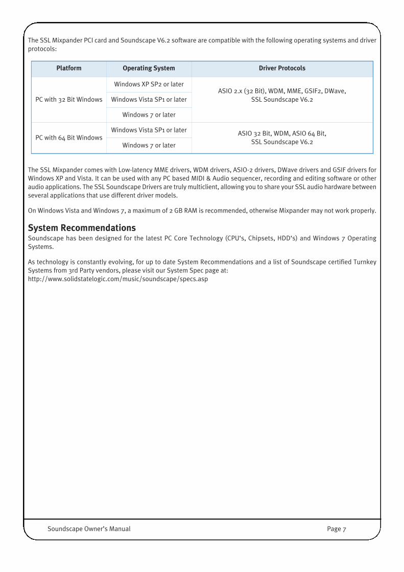
The SSL Mixpander PCI card and Soundscape V6.2 software are compatible with the following operating systems and driverprotocols:
The SSL Mixpander comes with Low-latency MME drivers, WDM drivers, ASIO-2 drivers, DWave drivers and GSIF drivers forWindows XP and Vista. It can be used with any PC based MIDI & Audio sequencer, recording and editing software or otheraudio applications. The SSL Soundscape Drivers are truly multiclient, allowing you to share your SSL audio hardware betweenseveral applications that use different driver models.
On Windows Vista and Windows 7, a maximum of 2 GB RAM is recommended, otherwise Mixpander may not work properly.
System RecommendationsSoundscape has been designed for the latest PC Core Technology (CPU‘s, Chipsets, HDD‘s) and Windows 7 OperatingSystems.
As technology is constantly evolving, for up to date System Recommendations and a list of Soundscape certified TurnkeySystems from 3rd Party vendors, please visit our System Spec page at: http://www.solidstatelogic.com/music/soundscape/specs.asp
Platform Operating System Driver Protocols
PC with 32 Bit Windows
Windows XP SP2 or laterASIO 2.x (32 Bit), WDM, MME, GSIF2, DWave,
SSL Soundscape V6.2Windows Vista SP1 or later
Windows 7 or later
PC with 64 Bit WindowsWindows Vista SP1 or later ASIO 32 Bit, WDM, ASIO 64 Bit,
SSL Soundscape V6.2Windows 7 or later
Soundscape Owner’s Manual Page 7

INSTALLING FROM WEB DOWNLOADStart by downloading the Mixer/Soundscape V6.2 Combo Installer from the SSL website: http://www.solidstatelogic.com/music/soundscape/downloads.asp
When you unzip the downloaded file, you will find four folders within it.
1. The SSL Soundscape family driver; This is a driver which allows all of the relevant SSL sound cards to be run on thecomputer. Note that your SSL sound card comes with a CD which also contains this driver. Installation of the driver isdescribed in the documentation included with each product.
2. The SSL Soundscape & Mixer; This is the main installer for Soundscape and is described below in detail. 3. Console Manager; This installer is included for legacy purposes as the software has been replaced by SSL Console Control.4. Resources; This folder includes all user documentation referenced by Soundscape’s Help menu.
Main Installation ProcedureSimply unpack the download into a folder and start SSL Soundscape Setup v6.2combo installer wizard.
Once the combo installer wizard is started (depending on the Windows versionyou may be prompted with some dialogue boxes to confirm that you really,really want to run this Installer)
Click Next.
In the next screen, choose the components you wish to install – Soundscape and its Mixer,along with optional extras Console Control and Pro Convert – and click Next.
The combo installation will now begin, as indicated by the progress screen which isdisplayed.
During the combo installation, the main Soundscape setup dialogue will open in a newwindow – click Next to start the Soundscape installation process.
Note that there may be a short pause before the buttons become available.
Please note that although you can select a different installation folder than the defaultoffered, the SSL Mixer & Soundscape user manuals and support procedures will alwaysrefer to the default installation folders. We therefore recommend using the defaultinstallation locations.
Click Next.
Page 8 Soundscape Owner’s Manual
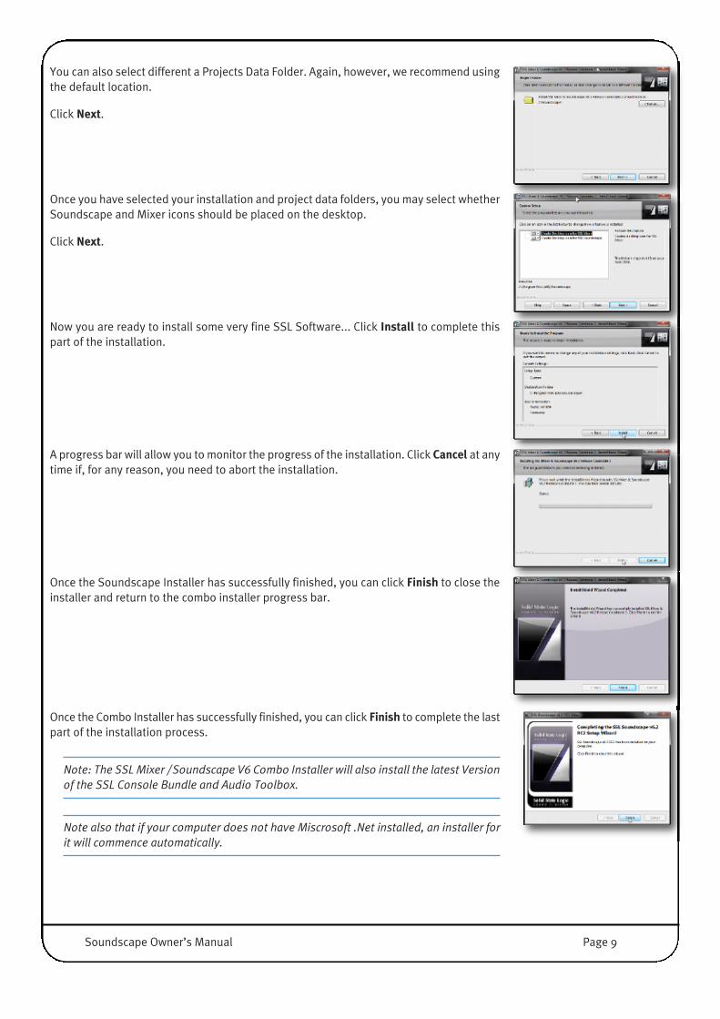
You can also select different a Projects Data Folder. Again, however, we recommend usingthe default location.
Click Next.
Once you have selected your installation and project data folders, you may select whetherSoundscape and Mixer icons should be placed on the desktop.
Click Next.
Now you are ready to install some very fine SSL Software... Click Install to complete thispart of the installation.
A progress bar will allow you to monitor the progress of the installation. Click Cancel at anytime if, for any reason, you need to abort the installation.
Once the Soundscape Installer has successfully finished, you can click Finish to close theinstaller and return to the combo installer progress bar.
Once the Combo Installer has successfully finished, you can click Finish to complete the lastpart of the installation process.
Note: The SSL Mixer / Soundscape V6 Combo Installer will also install the latest Versionof the SSL Console Bundle and Audio Toolbox.
Note also that if your computer does not have Miscrosoft .Net installed, an installer forit will commence automatically.
Soundscape Owner’s Manual Page 9

INSTALLING DSP AND VST PLUG-INSSSL Soundscape format DSP plug-insIf you have SSL Soundscape plug-ins to install which were not included in the main installation, you will find note on theinstallation in the documentation which came with them.
First, close all the Soundscape or Mixer Applications, double click on the plug-in’s installer application icon and follow theinstructions.
If you have installed Soundscape in its default folder, the installation will be straight forward; If Soundscape is installed in alocation other than the default folders you might need to point the Installer to your Soundscape install location.
After the plug-ins have been correctly installed, launch Soundscape and enter the plug-In password you have received byemail into the appropriate line in the Options Menu. Authorising plug-ins is explained in detail in the ‘Options Menu’ sectionof Chapter 5.
Please note that when working with Windows Vista or Windows 7, you may have to run the installer in compatibilitymode for Windows XP (right-click Installer Program / Properties / Compatibility Tab).
Note that DSP plug-ins are not available with a MadiXtreme.
VST format plug-insThe process of installing VST format plug-ins may vary depending on the developer’s installation process. However, many VSTManufacturers install the VST.DLL files by default in: C:\Program Files\Steinberg\VstPlugins.
For Soundscape to be able to work with installed VST plug-ins, their DLL files must be present in SSL Soundscape V6’s defaultVST folder, which is under normal circumstances (=you used our default locations to Install Soundscape V6) : C:\Program Files\Soundscape\MixElem\VST
If it is not possible to re-direct the plug-in installation to Soundscape’s VST folder you will need to manually COPY the DDLfiles to Soundscape’s VST folder.
At startup, Soundscape scans the VST folder and subfolders (Solid State Logic in the example above) and a small windowappears in front of the splash screen where the plug-in name is displayed while loaded.
Note that the Program Folder for 32 Bit Apps on Win 7-64 (or Vista 64) is called Program Files (x86)
Page 10 Soundscape Owner’s Manual
3. Soundscape Quick Start Guide
The purpose of this chapter is just to get you going with Soundscape. You will learn how to configure your system and createyour first project, then we will introduce you to a handful of Soundscape-specific terms and workflows.
Experienced Soundscape operators will learn how to migrate their Projects to V6 at the end of this chapter.
Please Note: This chapter does not explain functionality in detail. See Chapter 4 for a details of the functions described,and then Chapter 5 to really understand the unique Soundscape concepts and how they help you to speed up youraudio life function by function.
Curious? Let's dive right in....
SSL MIXER OR SSL SOUNDSCAPE?The SSL Mixer/Soundscape installer includes two applications, both of which share identical mixing functions, run on thesame hardware and (in many applications) do the same Mixing job; However, they are developed to perform different tasks:
SSL MixerThe Mixer’s main purpose is to work with other audio software such as Cubase/Nuendo, Sonar, Reason, etc, taking care ofrouting and audio processing (before or after the DAW's software input) and performing mixing and monitoring tasks in ‘DSPRealtime’ (4 samples).
It may also be used as a standalone Software Mixer, taking advantage of SSL hardware’s near zero latency and high qualityDSP processes to create the most flexible, software controlled, hardware console on the planet.
SSL SoundscapeSoundscape is designed to work as a standalone Digital Audio Workstation, capable of reliably performing recording andsophisticated editing tasks; Its built-in mixer section is identical to the SSL Mixer, but features full automation within thesoftware. In other words, with Soundscape, the Mixer is already built in.
The seamless collaboration between DAW and Mixing functionality inside Soundscape is ideal for mission-critical applicationsincluding Live Recording, high channel count Music Production, Broadcast, Post and Restoration.
SSL Soundscape and SSL Mixer togetherBoth software elements may be run simultaneously if necessary – for example, if two different and independent setups aredesired. In this way, you might use the SSL Mixer to perform sub-mixing tasks from live inputs or sequencing software, andat the same time run Soundscape to play backing tracks, record live or edit in real time.
It is important to mention that each software entity uses any SSL Card exclusively, so you need at least two SSL cardsto run Mixer and Soundscape simultaneously (i.e. a MX4 and a Mixpander, both connected to an Alpha Link or MADIiBox interface). To assign each program to work on a different card, you must configure the Unit Configurator utility in the Settingsmenu of the Mixer and Soundscape, as explained below.
Soundscape Owner’s Manual Page 11
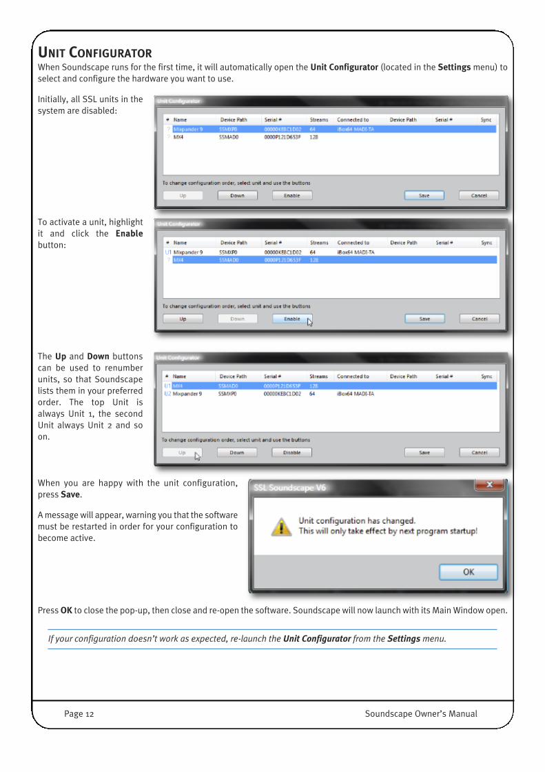
UNIT CONFIGURATORWhen Soundscape runs for the first time, it will automatically open the Unit Configurator (located in the Settings menu) toselect and configure the hardware you want to use.
Initially, all SSL units in thesystem are disabled:
To activate a unit, highlightit and click the Enablebutton:
The Up and Down buttonscan be used to renumberunits, so that Soundscapelists them in your preferredorder. The top Unit isalways Unit 1, the secondUnit always Unit 2 and soon.
When you are happy with the unit configuration,press Save.
A message will appear, warning you that the softwaremust be restarted in order for your configuration tobecome active.
Press OK to close the pop-up, then close and re-open the software. Soundscape will now launch with its Main Window open.
If your configuration doesn’t work as expected, re-launch the Unit Configurator from the Settingsmenu.
Page 12 Soundscape Owner’s Manual

BASIC CONFIGURATIONClock SynchronisationAny digital audio system must be properly clocked to a common clock source. In a single Alpha Link configuration, the MX4or MadiXtreme needs to be locked to the Alpha Link or vice versa. When both the soundcard and the Alpha Link are clockedinternally (=no Synchronisation of the clocks) you will hear audible clicks whenever the MADI Frames get too far off.
Select Master Clock from the Settings menu to configure the clock sourcefor the sound card:
In a system with a single MX4 or MadiXtreme, the choices on the right are available. To make thesoundcard the clock master, select Internal. Alternatively, to make it a clock slave to the connectedaudio I/O, choose MADI A, MADI B or Word Clock.
A connected Alpha-Link needs to be clocked appropriately. If the soundcard is set to Word Clock, a BNCCable from the Alpha-Link’s Word-Clock Out needs to be connected to the soundcard’s Word-clockconnector.
To make a single Mixpander system the clock master, select Internal. Alternatively, set it’s clock to beslaved to the connected Alpha-Link by simply choosing one of the digital input ports.
Available inputs will vary depending on the Alpha-Link, iBox or legacy Soundscape 32 connected to theMixpander‘s expansion port.
Master Clock can be transmitted and received in a number of ways, depending on the type of cards andconverters used in your system. The Word-Clock connectors are an obvious option. MADI, Adat, TDIF, orAES/EBU are also suitable for clocking when two or more SSL Cards are connected to appropriatelyequipped SSL Alpha-Link Converters.
The Soundscape and Mixer software can work with any combination of MadiXtreme, MX4 and Mixpander cards. Within theMixer environment, the cards are identified as Unit 1, Unit 2, Unit 3 etc. All cards in a multiple unit system must also besynchronised to a common Master Clock signal which can be provided by one of the cards or by an external device.
NOTE: In a simple Setup of one MX4 Card plus Alpha-Link Converter, it is advisable to always use the converter's Clockas a Master. Set MX4 to Master Clock MADI or Wordclock, and the Alpha-Link to Internal Clock.
For a multiple Mixpander system, units 2 and above must be operated as a clock slaves, receiving the Clock signal fromanother unit via their Word Clock or MADI input. The unit that provides the Clock signal must be set to output Worm Clock.Worm Clock is a modified Word Clock signal that includes sample-accurate start/stop synchronisation information for the unitvia the SSL Alpha-Link Wordclock I/O. The Master Clock parameter for the slave unit must be set to Word Clock, which alsoenables Worm Clock synchronisation.
For more information on Master Clock settings, please refer to the Master Clock and W/S Clock Out sections of the MenuReference chapter of this manual.
NOTE: Only use the Worm Clock setting when the clock signal is transmitted to an SSL Alpha Link (or iBox 24/48/64).Other SSL hardware devices may not synchronise correctly if they receive Worm Clock.
Soundscape Owner’s Manual Page 13
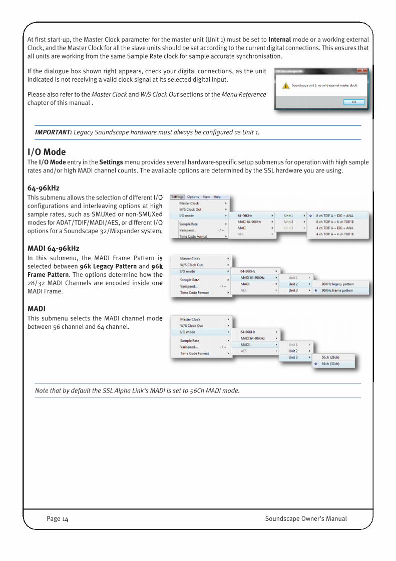
At first start-up, the Master Clock parameter for the master unit (Unit 1) must be set to Internal mode or a working externalClock, and the Master Clock for all the slave units should be set according to the current digital connections. This ensures thatall units are working from the same Sample Rate clock for sample accurate synchronisation.
If the dialogue box shown right appears, check your digital connections, as the unitindicated is not receiving a valid clock signal at its selected digital input.
Please also refer to the Master Clock and W/S Clock Out sections of the Menu Referencechapter of this manual .
IMPORTANT: Legacy Soundscape hardware must always be configured as Unit 1.
I/O ModeThe I/O Mode entry in the Settings menu provides several hardware-specific setup submenus for operation with high samplerates and/or high MADI channel counts. The available options are determined by the SSL hardware you are using.
64-96kHzThis submenu allows the selection of different I/Oconfigurations and interleaving options at highsample rates, such as SMUXed or non-SMUXedmodes for ADAT/TDIF/MADI/AES, or different I/Ooptions for a Soundscape 32/Mixpander system.
MADI 64-96kHzIn this submenu, the MADI Frame Pattern isselected between 96k Legacy Pattern and 96kFrame Pattern. The options determine how the28/32 MADI Channels are encoded inside oneMADI Frame.
MADIThis submenu selects the MADI channel modebetween 56 channel and 64 channel.
Note that by default the SSL Alpha Link‘s MADI is set to 56Ch MADI mode.
Page 14 Soundscape Owner’s Manual

Timecode SynchronisationTimecode synchronisation is managed via the Sync Setup display, located inthe Settings menu. Incoming MTC and MMC, and outgoing MTC can be enabledand configured.
For systems with a Soundscape 32 card, synchronisation information is passedto Units 2 and above by setting each unit's W/S Clock Out to Wormclock.
For detailed information about the Sync In options, please read theSynchronisation section in the Menu Reference chapter of this User Guide.
Authorising the Soundscape Software and ModulesClick the Options menu to open the Passwords window. Enter your passwordfor the ‘SOUNDSCAPE Version 6’, ‘Version 2.xx Mixer’ (MIX), Audiotoolbox(ATB), along with any other plug-ins such as SSL Console EQ and Filters (SEQ),SSL Console Dynamics (SCD) and SSL Bus Compressor (SBC).
The Passwords for your SSL Soundscape hardware can be found on a label on the card itself or on the registration cardinside the MX4 box.
If you have registered your units on our website, theyare also available in your MySSL account: http://store.solidstatelogic.com/user
If you have purchased any optional effects plug-ins,this is also the place where you enter theirpasswords. Please check the Options Menu sectionof the Menu Reference chapter of this User Guide.
IMPORTANT: For MX4 and Mixpander, allpasswords need to be entered with the prefix ‘M’.
Entering an incorrect password will result in the following:
• V2. Mixer (MIX): You will not hear any sound or be able to record or play back. Soundscape will notify you with an InvalidOptional Module Password message and deactivate the Mixer (Mixer Inactive).
• Soundscape (SS6): Without a Password, the Soundscape Software is limited to Recording and Playback of the first 16Tracks (TRK 1-16). Everything else is fully functional and you can explore the power of Soundscape. However, if you haven'tpurchased Soundscape, you will also not have received the included Time Module Password, hence all Timestretch/PitchShift/Sample Rate Convert operations are not functional.
• MX4 Included Plug-Ins (ATB, SEQ, SCD, SBC): You will not be able to use any of the these plug-ins. If you load the defaultor any Standard Mixer or insert one of those Plug-Ins into a channel strip, Soundscape will notify you with an InvalidOptional Module Password message and deactivate the Mixer.
NOTE: Passwords are tied to the specific Hardware UID/Serial Number of the card(s) and can only authorise Moduleswhen the specific hardware is present in the in the current UNIT Configuration. The password-protected modules canthen be loaded onto any DSP card as long as this specific UID is present.
�
Soundscape Owner’s Manual Page 15

OPENING AN EXISTING MIXER AND ARRANGEMENTSSL Soundscape uses separate files for the Mixer and Arrangement, allowing for maximum flexibility. To get an idea of howSoundscape works, you may open pre-made Mixer and Arrangement files. You can download sample Soundscape Projects here: http://www.solidstatelogic.com/music/soundscape/downloads.asp
In the File menu, click Open, then locate and load the Mixer file and the Arrangement file.
To assign an edit function to a mouse button, click on the appropriate icon located in the Toolbar with the required mousebutton. A little black bar will then be displayed under the icon on the corresponding side to remind you which tool is activefor which mouse button:
Using the left and right buttons while holding the [Alt] key will allow you assign two further tools. These are indicated by ared bar under the icon, on the corresponding side. You will need to press the [Alt] key while clicking to use these tools.
When mixing, it might be useful to know that faders and knobs in the Mixer can be controlledthree ways: • by grabbing them with the mouse,• by positioning the mouse over the controls or value displays and moving the scroll wheel, • by double clicking on them and entering the desired value.
NOTE: Several Mixer files are installed with SSL Soundscape. If you installed Soundscape using the default settings, theMixer file’s path is C:\Soundscape\Mix\ . Selecting Open Mix under the Filemenu will automatically find this folder.
Important: MadiXtreme Cards do not have any DSP's to process Plug-Ins or standard Faders, Sends or Panpots on.MadiXtreme I/O's are also hardwired to the Native Track Element. In other words, Track1 is connected to Input 1 and MadiOutput1, and so on.
Page 16 Soundscape Owner’s Manual
CREATING YOUR FIRST SOUNDSCAPE PROJECTRecording Audio
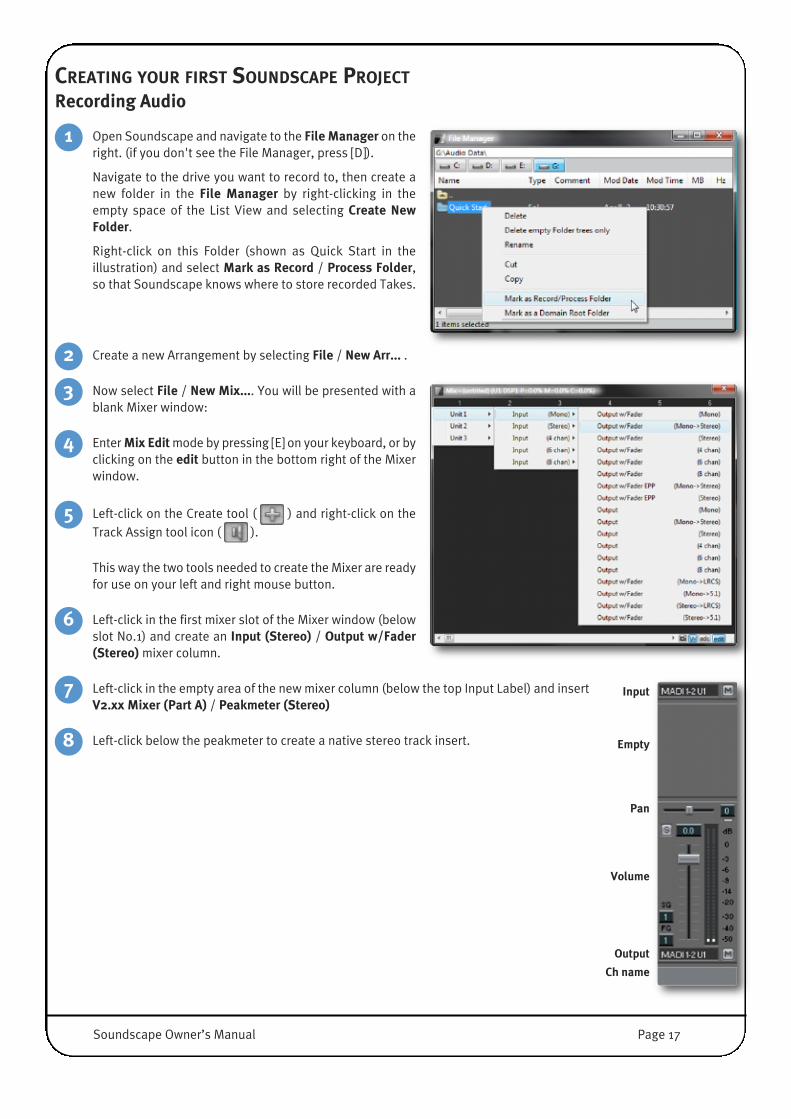
Open Soundscape and navigate to the File Manager on theright. (if you don't see the File Manager, press [D]).
Navigate to the drive you want to record to, then create anew folder in the File Manager by right-clicking in theempty space of the List View and selecting Create NewFolder.
Right-click on this Folder (shown as Quick Start in theillustration) and select Mark as Record / Process Folder,so that Soundscape knows where to store recorded Takes.
Create a new Arrangement by selecting File / New Arr... .
Now select File / New Mix.... You will be presented with ablank Mixer window:
Enter Mix Edit mode by pressing [E] on your keyboard, or byclicking on the edit button in the bottom right of the Mixerwindow.
Left-click on the Create tool ( ) and right-click on theTrack Assign tool icon ( ).
This way the two tools needed to create the Mixer are readyfor use on your left and right mouse button.
Left-click in the first mixer slot of the Mixer window (belowslot No.1) and create an Input (Stereo) / Output w/Fader(Stereo) mixer column.
Left-click in the empty area of the new mixer column (below the top Input Label) and insertV2.xx Mixer (Part A) / Peakmeter (Stereo)
Left-click below the peakmeter to create a native stereo track insert. 8
7
Pan
Volume
Ch name
Output
Input
Empty
6
5
4
3
2
1
Soundscape Owner’s Manual Page 17
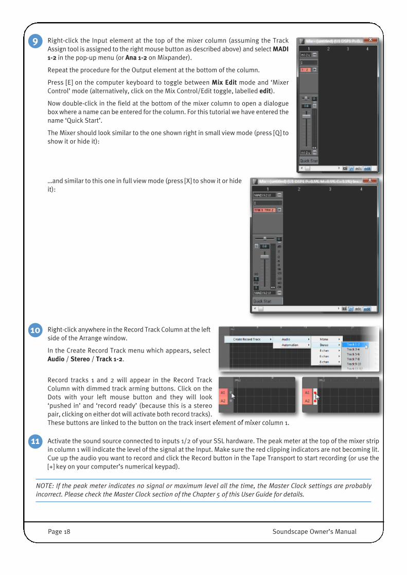
Right-click the Input element at the top of the mixer column (assuming the TrackAssign tool is assigned to the right mouse button as described above) and select MADI1-2 in the pop-up menu (or Ana 1-2 on Mixpander).
Repeat the procedure for the Output element at the bottom of the column.
Press [E] on the computer keyboard to toggle between Mix Edit mode and ‘MixerControl’ mode (alternatively, click on the Mix Control/Edit toggle, labelled edit).
Now double-click in the field at the bottom of the mixer column to open a dialoguebox where a name can be entered for the column. For this tutorial we have entered thename ‘Quick Start’.
The Mixer should look similar to the one shown right in small view mode (press [Q] toshow it or hide it):
…and similar to this one in full view mode (press [X] to show it or hideit):
Right-click anywhere in the Record Track Column at the leftside of the Arrange window.
In the Create Record Track menu which appears, selectAudio / Stereo / Track 1-2.�
Record tracks 1 and 2 will appear in the Record TrackColumn with dimmed track arming buttons. Click on theDots with your left mouse button and they will look‘pushed in’ and ‘record ready’ (because this is a stereopair, clicking on either dot will activate both record tracks).These buttons are linked to the button on the track insert element of mixer column 1.
Activate the sound source connected to inputs 1/2 of your SSL hardware. The peak meter at the top of the mixer stripin column 1 will indicate the level of the signal at the Input. Make sure the red clipping indicators are not becoming lit.Cue up the audio you want to record and click the Record button in the Tape Transport to start recording (or use the[+] key on your computer’s numerical keypad).
NOTE: If the peak meter indicates no signal or maximum level all the time, the Master Clock settings are probablyincorrect. Please check the Master Clock section of the Chapter 5 of this User Guide for details.
11
10
9
Page 18 Soundscape Owner’s Manual
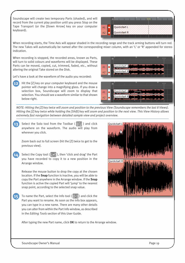
Soundscape will create two temporary Parts (shaded), and willrecord from the current play position until you press Stop on theTape Transport (or the [Down Arrow] key on your computerkeyboard).
When recording starts, the Time Axis will appear shaded in the recording range and the track arming buttons will turn red.The new Takes will automatically be named after the corresponding mixer column, with an ‘L’ or ‘R’ appended for stereoindication.
When recording is stopped, the recorded areas, known as Parts,will turn to solid colours and waveforms will be displayed. TheseParts can be moved, copied, cut, trimmed, faded, etc., withoutaltering the original Take stored on the Disk.
Let’s have a look at the waveform of the audio you recorded:
Hit the [Z] key on your computer keyboard and the mousepointer will change into a magnifying glass. If you draw aselection box, Soundscape will zoom to display thatselection. You should see a waveform similar to that shownbelow-right.
NOTE: Hitting the [Z] key twice will zoom and position to the previous View (Soundscape remembers the last 8 Views).Hitting the [Z] key twice while holding the [Shift] key will zoom and position to the next view. This View History allowsextremely fast navigation between detailed sample view and project overview.
Select the Solo tool from the Toolbar ( ) and clickanywhere on the waveform. The audio will play fromwherever you click.
Zoom back out to full screen (hit the [Z] twice to get to theprevious view).
Select the Copy tool ( ), then ‘click and drag’ the Partyou have recorded to copy it to a new position in theArrange window.
Release the mouse button to drop the copy at the chosenlocation. If the Snap function is inactive, you will be able tocopy the Part anywhere in the Arrange window. If the Snapfunction is active the copied Part will ‘jump’ to the nearestsnap point, according to the selected snap value.
To name the Part, select the Info tool ( ) and click thePart you want to rename. As soon as the info box appears,you can type in a new name. There are many other detailsyou can alter from within the Part Info window, as describedin the Editing Tools section of this User Guide.
After typing the new Part name, click OK to return to the Arrange window.
15
14
13
12
Soundscape Owner’s Manual Page 19

Recording AutomationRecording automation data is very similar to audio recording, and shares much of the same procedure. Follow the stepsbelow to see how to record dynamic automation moves.
Recorded automation data can be viewed and edited in pretty much the same way as audio Takes, with the addition of threespecific tools which are described in the Mixer Automation section in Chapter 4 of this manual. Automation data contains‘automation events’, and these come in two varieties: ‘continuous events’ for faders and pots and ‘stepped events’ for buttonsor ‘vintage style’ stepped controls.
Enable Automation:For any automation data to be recorded or played back, Automation must beenabled. This can be done by clicking the Automation Enable toggle located inthe bottom, right corner of the Mixer window, or by pressing [G] on thecomputer keyboard.
When the button is ‘illuminated’ in blue, Automation is globally enabled.
Automation data is recorded on the automation track that matches the Mixer'sColumn slot number.
Create an automation Record TrackIn order to record automation, create an Automationrecord track by right-clicking in the Record Track Column.
Arm the Automation TrackThe track arming button works just like an Audio Track Arming button.
Record AutomationMake sure no audio tracks are armed, then start recording automation bypressing the record button or [+] on your keyboard. Now move the desired knobson the Column Number on which you are currently recording. You can alsocreate multiple automation tracks to record dynamic changes on multiple MixerColumns.
Press Stop to finish the automation recording.5
4
3
2
1
Page 20 Soundscape Owner’s Manual

Curve Select Tool With the Automation Curve Select tool ( ), you canselect which of the automation curves you have recordedis displayed.
Automation Events Thinning ToolAfter clicking on an automation part, you may enter a thinning factor ( ) to reduce the number of automationnodes/points and make it easier to edit the curves graphically. A thinning factor of 200 reduces the amount ofautomation nodes slightly, a factor of 1000 reduces the amount of nodes heavily and only maintains the most importantnodes (ie. Min or Max of an almost linear Fade In).
In the example to the right, an automation part was recorded using a motorised fader on anSSL Console to perform an S-Curve like Fade In.
After applying a Thin Factor of 1000, only the shallow slope at the beginning, the steeperslope in the middle and the shallower slope close before the Maximum are maintained inthe automation part.
Automation Event Editing tool�The automation curves may be edited by clicking and dragging
the automation nodes with the pencil tool ( ).
WARNING: Unlike audio Parts, automation Parts can contain several layers of data (automation curves). Simplypunching-in on an automation Part (in Normal Record mode) will overwrite all the data in the ‘punched’ section of thisPart (i.e., all the automation curves are affected). The Touch Recordmode or Touch Record Till Stopmode should beselected for automation punch in/out with no risk of losing any data that is not ‘touched’.
8
7
6
Soundscape Owner’s Manual Page 21

MIXING, VST BUFFERS AND ADCAny digital audio processing takes a small amount of time to be performed. When mixing and applying several processes toan audio track (like EQ, compression, etc.) the cumulative delay (‘latency’) of one track may differ significantly from the rest,causing phase problems and even audible misalignment.
While all Soundscape-compatible DSP Plug-Ins and Mixer Elements (and almost all Soundscape Legacy DSP Plug-Ins) do notneed any additional buffer on top of the central DSP buffer inside an MX4 or Mixpander card (4 Samples round-trip In toOut!), any external processing (either a rack mount FX Device connected to the Converter via audio cables or a native VST/VSTiPlug-In inserted into the Mixer) will add latency.
This delay is most noticeable when inserting VST processes, as the audio has to travel to the computer’s CPU, be bufferedfor processing, and travel back to Soundscape.
The amount of buffering by the CPU is can be defined with the Native mixer elements sample buffer size option value in theSettings / Preferences /Mixer menu.
The default value is 128 samples, which should comfortably provide enough time for a modern CPU to process any modernplug-in. If you hear audible clicks or crackles, or feel that the PC is struggling to cope with the processing demands, increasethis value in powers of two up to 8192 samples. (ie. 64, 128, 256, 512, 1024...8192)
If an invalid value is entered, it will be replaced with the closest valid value. The Native elements sample buffer size may alsoneed to be increased when mixing very large arrangements with hundreds of VST plug-ins. Since the current VST technologyis NOT reporting the loss of samples (=distortion, crackles, clicks) reliably, it is a good idea to set the buffers to the nexthigher value than appears to be necessary.
However, please note that buffer sizes above 1024 samples can have the reverse effect, since the amount of RAM requiredto create all the input and output buffers for each plug-in may result in a large system overhead while moving samplesbetween RAM and CPU.
Although the buffer size may be set to a minimum of 64 samples in a modern computer, some sophisticated audio plug-insmay take a longer time to be processed. Also, a chain of VST plug-ins will add an input and output buffer for each one,resulting in multiple processing delays.
Large processing delays can be solved by adding compensating delays to some of the‘faster’ signal paths, allowing audio signals to be perfectly aligned at the outputs. Toactivate the Automatic Delay Compensation on the Soundscape Mixer, click the adcbutton located in the right bottom corner of the Mixer window. When the adc buttonis ‘illuminated’ in blue, the compensation is active.
IMPORTANT: It's not always practical to use Automatic Delay Compensation during recording, since all the signals mustbe aligned with the ‘slowest’ one (i.e., the one with the highest cumulated processing delay). Any signal going throughthe system may then be delayed including the artist monitoring paths. Soundscape offers a variety of strategies toexclude certain audio paths (like Monitoring) from being delayed by the ADC. Please read the ‘Automatic DelayCompensation’ section in Chapter4 of this User Guide for more information.
�
Page 22 Soundscape Owner’s Manual

4. Soundscape Operations
MAIN SCREEN OVERVIEWThe main screen is customisable, and you can chose to only display the Soundscape function windows which you find useful.These include the Arrange, Mixer, File Manager, Marker Directory, Video File Player, Big Current Time, Buffer Activity and 9-Pin Sync windows, along with the main Soundscape Window which has the user definable Toolbar and Status Bar across thetop and the tape transport bar across the bottom. Each window can be hidden or recalled with a saved size and position, witha single keyboard shortcut or menu selection.
Docking Arrange and File Manager Windows to the Main Window.
�
For multi-monitor setups, all Soundscape windows can be freely placed anywhere inside the extended desktop. A SoundscapeTimeline Project is called an Arrangement, and has 1024 virtual Tracks to create adventurous projects. It can also contain upto 131072 individual Parts (Blocks of Audio on the timeline) which use up to 131072 audio Takes (Audio Files on the Disk). AnArrangement can be created from scratch, or a saved Arrange file (.ARR) can be loaded.
Soundscape’s extremely flexible Mixer can have up to 128 Mixer Columns (or Channel Strips) that can each be Mono, Stereoor up to 8 Channels wide. Mixers are stored separately as .MIX files, and while you are still wondering why the Mix is not storedin the Arrangement, we can assure you that this will actually revolutionise the way you work with different Mix Versions andfull A/B comparison complete Mixers.
The Arrange file, Mix file and any associated Audio Takes can be backed up to any logical PC drive, to secure your data.
Soundscape Owner’s Manual Page 23
TOOLBAR�
At top of the main Soundscape window you will find the main menus, the Toolbar – which is used for most on-screen editing– and the Status Bar.
Note that the main menus are explained in detail in Chapter 5.
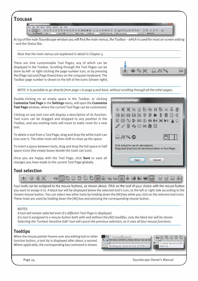
There are nine customisable Tool Pages, any of which can bedisplayed in the Toolbar. Scrolling through the Tool Pages can bedone by left- or right-clicking the page number icon, or by pressingthe [Page Up] and [Page Down] keys on the computer keyboard. TheToolbar page number is shown to the left of the icons (shown right).
NOTE: It is possible to go directly from page 1 to page 9 and back, without scrolling through all the other pages.
Double-clicking on an empty space in the Toolbar, or clickingCustomize Tool Page in the Settings menu, will open the CustomizeTool Page window, where the current Tool Page can be customized.
Clicking on any tool icon will display a description of its function.Tool icons can be dragged and dropped to any position in theToolbar, and any existing tools will move to make room for a newtool.
To delete a tool from a Tool Page, drag and drop the white trash canicon over it. The other tools will then shift to close up the space.
To insert a space between tools, drag and drop the full space or halfspace icons (the empty boxes beside the trash can icon).
Once you are happy with the Tool Page, click Save to save allchanges you have made to the current Tool Page globally.
Tool selection�
Four tools can be assigned to the mouse buttons, as shown above. Click on the tool of your choice with the mouse buttonyou want to assign it to. A black bar will be displayed below the selected tool’s icon, to the left or right side according to thechosen mouse button. You can select two other tools by holding down the [Alt] key while you click on the relevant tool icons.These tools are used by holding down the [Alt] key and pressing the corresponding mouse button.
NOTES: A tool will remain selected even if a different Tool Page is displayed.If a tool is assigned to a mouse button both with and without the [Alt] modifier, only the black bar will be shownSelecting the ‘Context Sensitive Edit’ tool will cancel the previous selection, as it uses all four mouse functions.
TooltipsWhen the mouse pointer hovers over any editing tool or otherfunction button, a tool tip is displayed after about a second.Where applicable, the corresponding key command is shown.
Page 24 Soundscape Owner’s Manual

STATUS BAR
�
The Status Bar, displayed underneath the Toolbar, displays some of the more commonly accessed parameters from theSettings menu, and allows them to be selected quickly.
The bar shows the current mouse position within the Arrangement, the current status and selected value of the Snap setting,the Synchronisation mode, Project Sample Rate, Frame Rate, Sample Resolution and Record File Format for newrecorded/processed Takes.
The time interval between the Left and Right Locators is displayed in bars/counts/ticks or SMPTE + sample extension at thecurrent Frame Rate.
NOTE: The Status Bar can be turned on or off in the Viewmenu.
Mouse positionThe mouse position readout is continuously updated to the currentposition of the mouse pointer in the Arrange window. Its resolution isdetermined by the Snap setting (if active), while the Time Axis setting(SMPTE or bars/counts/ticks) determines the time position’s units. InSMPTE mode, the sample within each frame is also shown.
The number displayed to the left of the position display indicates whichvirtual track (horizontal position) the mouse is currently over. This isuseful for keeping Parts on the same virtual track in large Arrangements.
The mouse resolution across the display depends on the horizontal screen resolution, so do not expect to be able to movein steps of one frame when you have five minutes of the Arrangement are displayed screen. However if you zoom in, themouse position readout will be as expected.
The theoretical resolution of musical time divisions is 960 ticks per quarter note, and the actual time value of one tick isvariable depending on the Tempo. The resolution of SMPTE time divisions is a 100th of a frame, irrespective of Tempo, butis variable according to the Frame Rate selected under the Settings / Time Code Format menu.
However, sample accuracy is often required when editing digital audio. If SMPTE time is selected from the Settings / TimeAxis menu, the mouse position readout employs a format that makes sample accurate editing with the mouse easy. It isnecessary to use the highest zoom in level so that each pixel on the screen shows one single sample, and the Snap functionneeds to be inactive.
The complete format is: hours:minutes:seconds:frames:samples, preceded with the number of the virtual track where themouse pointer is positioned.
Bars/counts/ticks mode SMPTE mode
Virtual Track
Soundscape Owner’s Manual Page 25
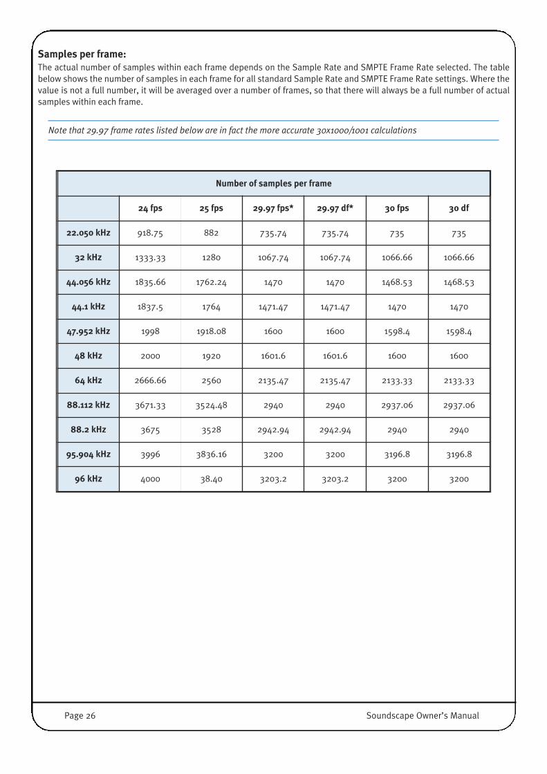
Samples per frame:The actual number of samples within each frame depends on the Sample Rate and SMPTE Frame Rate selected. The tablebelow shows the number of samples in each frame for all standard Sample Rate and SMPTE Frame Rate settings. Where thevalue is not a full number, it will be averaged over a number of frames, so that there will always be a full number of actualsamples within each frame.
Note that 29.97 frame rates listed below are in fact the more accurate 30x1000/1001 calculations
Number of samples per frame
24 fps 25 fps 29.97 fps* 29.97 df* 30 fps 30 df
22.050 kHz 918.75 882 735.74 735.74 735 735
32 kHz 1333.33 1280 1067.74 1067.74 1066.66 1066.66
44.056 kHz 1835.66 1762.24 1470 1470 1468.53 1468.53
44.1 kHz 1837.5 1764 1471.47 1471.47 1470 1470
47.952 kHz 1998 1918.08 1600 1600 1598.4 1598.4
48 kHz 2000 1920 1601.6 1601.6 1600 1600
64 kHz 2666.66 2560 2135.47 2135.47 2133.33 2133.33
88.112 kHz 3671.33 3524.48 2940 2940 2937.06 2937.06
88.2 kHz 3675 3528 2942.94 2942.94 2940 2940
95.904 kHz 3996 3836.16 3200 3200 3196.8 3196.8
96 kHz 4000 38.40 3203.2 3203.2 3200 3200
Page 26 Soundscape Owner’s Manual

SnapThe Snap function [H] defines a global time grid for almost any editing and positioning function.Clicking on the Snap drop-down box opens the list of possible values.
With Snap active, any time position markers, Left and Right Locators and Current Locator willautomatically snap to the next point in the selected grid, and edits will be performed on theclosest Snap Point; This allows fast and accurate editing without the need to zoom in. Forexample, when Snap is set to Bar, cuts will be made at the barline nearest the mouse position.
The Snap function is also useful for positioning the Locators for punch in/out recording exactlyon beats. For example, if you want to edit the audio at any quarter-bar, set Snap to 1/4.
While working with picture, setting Snap to Frame can be used to quickly place audio clipsexactly as required.
If a part is moved, its start will be placed at a Snap Point. You can drag the new Part with theCopy tool, and as long as you release the mouse close enough to the target position it will snapinto position perfectly.
The first item, labelled Active, allows activation/deactivation of the Snap function. The [H] keyon the keyboard toggles this setting.
The currently selected Snap value appears black in the drop-down box if the Snap function isactive; It is dimmed if inactive.
Note that with Snap active, the mouse position readout shows the time code of a potentialedit, not the precise mouse position. (please see above)
Certain editing tools – such as the Move Vertical or Copy to Locator tools – are not subject to the Snap function. The Slip andRepeat tools respond to the Snap function only if the selected Snap value is a musical or SMPTE based time division, asdescribed later.
If the selected Snap value is Part, Marker, Locator, or Prt+Mrk+L, the beginning and end time positions of all Parts, theMarkers, the Left, Right, and Current Locators, or all of these together (Prt+Mrk+L) will respectively act as snap pointswhenever a snap-sensitive edit or operation is performed close enough to one of them, along with any embedded SnapPoints (as described in the Snap Point Edit tool of the Editing Tools section in this chapter). If the position for an edit is outof range, the Snap function will have no effect.
In the above cases, the same ‘object’ could be subject to the Snap function and also act as a snap point itself. For example,if the selected value is Prt+Mrk+L, a Part’s beginning could be snapped to the Current Locator, and then the Current Locatorcould be snapped to the end of that Part.
If the Snap function is active and the selected snap value is a musical time division (Bar, 1/4, 1/8, 1/16, 1/32, 1/4T, 1/8T,1/16T, 1/32T), or a SMPTE or SMPTE-related time division (Second, Half Sec, Frame, QFrame, 10thFrm, 100thFrm), then allsnap-sensitive edits and the positioning of the Markers, Left and Right Locators, or Current Locator always occur at the closestsnap point. There is no ‘safe distance’ from the snap points.
NOTES: The Markers, Left/Right Locators and the Current Locator can be set to any time position regardless of the snap settingswhen entering time code values with the keyboard. ‘On the fly’ Locator dropping using key commands to place Markersor Locators, is not snap-sensitive either. If the active snap setting is Part, Marker, Locator, or Prt+Mrk+L, both beginning and end of the edited Part will snap.Please also read about the Snap Point Edit tool in the Editing Tools section of this chapter.�
Soundscape Owner’s Manual Page 27

Sync InThe Sync In box displays a list of ‘Synchronisation Slave’ modes also found in the Settings / Sync In menu. Options are: Off,MTC, LTC, VITC, and 9-Pin.
Pressing [M] on the computer keyboard sets the Sync In mode to Off, allowing Soundscape to beused as a Time Code Master.
MTC and LTC can be selected by pressing the [S] and [O] keys respectively. LTC, VITC, BITC and9-Pin are only available if the optional Soundscape Sync Board is installed in a legacy Soundscape32 unit and this Unit is present as Unit 1.
The 9-Pin option is only available if Controller, Synchro or Layback is selected in the Settings /9-Pin Operation Mode menu.
In Chase Slave or Trigger Slave modes, Soundscape will only respond to incoming Time Code if it is in Play or Record mode(i.e., if the Play or Record button has been clicked) unless the Auto Play/Stop when slave syncing option is enabled in theSettings / Sync Setup window.
IMPORTANT: External Time Code synchronisation is only available if there’s a Soundscape 32 unit in the system.
Sample RateClicking the SRate Drop Down box will display all available sample rates. Clicking on an entry willset Soundscape to operate at that rate. This can also be specified in the Settings / Sample Ratemenu.
When the Master Clock is set to an external input in the Settings / Master Clock menu, the SRatereadout displays the sample rate being received. The display will appear dimmed, indicating thatthe sample rate selection cannot be altered. Soundscape operates at sample rates up to 96kHz.
Whenever the Varispeed value in the Settings menu is not equal to 00.00%, the sample rate willbe displayed in red.
Frame RateClicking the arrow to the right of the FRate box will open a list with available frame rates.
This parameter can also be set in the Settings / Time Code Format menu.
Note that 29.97 frame rates are in fact the more accurate 30x1000/1001 calculations
Page 28 Soundscape Owner’s Manual

Record FormatThe Rec Fmt box shows Soundscape’s current recording file format and bit resolution.Clicking on its drop-down box allows you to select between 16 or 24 bit BWF broadcastwave file and 16 or 24 bit ATAK SSL Soundscape audio take format. Changing theformat will only affect newly recorded or processed audio Takes.
This option is also available in the Settings menu.
Master ClockThe MClk box shows the current master clock settings. The clocking options are shownfor each unit present in the system.
This option is also available in the Settings menu.
L<<−−>>R ReadoutThe L<<−−>>R readout shows the current time interval betweenthe Left and Right Locators.
The value is displayed in bars, counts, ticks or SMPTE+sample extension, according to the setting chosen for Time Axis in theSettings menu.
Soundscape Owner’s Manual Page 29

ARRANGE WINDOWThe Arrange window is where most of the real work happens. It shows the layout of your Arrangement, with up to 1024 virtualtracks displayed vertically. Active audio Parts are colour-coded when assigned to one of the 128 physical tracks (64 with oneMixpander). Active automation Parts can use any of the 128 automation tracks which are connected to the Mixer ColumnNumber.
Muted Parts appear greyed out with, their name and/or audio waveform/automation events dimmed; They are currently notassigned to an audio or automation track. When the Arrangement is played back, therefore, muted audio Parts will not beheard and automation Parts will not control Mixer Elements.
Creating and Opening ArrangementsTo create a new, empty Arrangement window, select the File menu’s NewArr... option.
If an Arrangement is already open and has unsaved changes, you needto save or lose those changes, or Cancel the operation and revert to theactive arrangement.
Automation Part
Audio Part
Muted Audio Part
Current Locator
Right Locator
Left Locator
Rec Arm Off
Rec Armed Auto Trk
Follow Current Location
Verticle Zoom In
Verticle Zoom Out
Zoom Rectangle
Horizontal Zoom InHorizontal Zoom Out
Audio Track
Marker Bar
Time Axis
Page 30 Soundscape Owner’s Manual

Selecting Open Arr... (or pressing [Ctrl]+[O]) brings up astandard Windows file browser.
Again, if an Arrangement is already open and hasunsaved changes, you need to save or lose the changes,or Cancel the operation completely to revert to theactive arrangement.
Arrangements can also be opened by double clickingan ARR file inside File Manager.
Appending ArrangementsAppend Arr... [Ctrl]+[A] adds a saved .arr File to the currently opened Arrangement at the Current Locator position.
Note that the Current Locator should be placed at the desired song position before using this option.
If Part overlaps are not allowed (As set in Settings / Preferences / Arrangement / Overlapping Parts (for new edits)), anyParts in the appended Arrangement which would overlap with Parts in the current Arrangement will not be loaded.
Arrangements can also be appended and visually positioned by dragging and dropping an Arrangement from File Manager.
Saving ArrangementsSave Arr... [Ctrl]+[S] saves the current Arrangement. Arrangements don't only store the list of Parts on the timeline, but alsoinclude project settings such as sample rate, frame rate, tempo, SMPTE offset, varispeed, L and R locators, markers, punchand loop button status, record setup, automation setup, and the assigned Record/Process folder.
Save Arr As... allows the Arrangement to be saved under a different name, using a standard Windows dialogue.
In order to keep compatibility with legacy Soundscape Systems, Arrangements can be saved as a Soundscape Editor V5.1compatible format using the Save Arr As V5.1 compatible format... option. This is only available if no WAV/BWF files areused by Parts inside the Arrangement.
Saving selected Parts as an ArrangementIf any Part is selected in the Arrange Window when you click Save Arr As..., a dialoguebox will appear (shown right).
This function allows you to only partially save an Arrangement and therefore createMulti Channel pieces which can be used in other Arrangements (using Append Arr...).
This can be useful for recurring Jingles, Openers or Sound FX.
Click No if you want to save the whole Arrangement.
Soundscape Owner’s Manual Page 31

Record TracksThe Record Track Column allows you to determine the virtual track position, record loop stack size and track arming statusfor the physical tracks. Any record track inserted in the Record Track Column can also determine the default output trackassignment for the corresponding virtual track when dragging Takes into the Arrangement or copying/moving Parts to adifferent virtual track.
Since Soundscape does NOT have a fixed relationship between virtual track and output assignments, record tracks can befreely moved without changing the track assignments of Parts that are already on a virtual track.
Right-clicking on the Record Track Column opens amenu where you can create an audio or automationrecord track on this virtual track (there can be up to 256virtual tracks). Audio record tracks can be created asmono tracks, stereo pairs or multichannel groups.
For automation record tracks, please note that youselect the Column Slot Number you want to automate inside the Mixer Window .
When using an MX4, there is also no fixed relation between track I/O assignments and the Mixer Column Number inSoundscape, hence Track 1 Audio (A1) could be connected to Mixer Column 10, making it necessary to create automation forthis audio track on Automation Track C10.
Note that with a MadiXtreme, there is a fixed relationship between I/O assignments and Mixer tracks.
Baffled? Confused? The good news is, you can assign Audio Track 1 to virtual Track 1 and Mixer Column 1... if you like to keepit simple!
Once created, a record track appears as a colour-codedslot in the Record Track Column, with a round ‘trackarming’ button.
If an audio record track has no corresponding trackinsert in the Mixer, or if an automation record track hasno corresponding mixer column, the rectangle will bedimmed and the track arming button will be absent.
NOTE: A mono Audio Record Track cannot be used ifit is connected to a Stereo Track Insert in the Mixer. Astereo Audio Record Track, however, will enable bothMono Track Inserts in the Mixer.
Right-clicking in a slot with an existing record track opens a slightly different menu. You canstill create an audio or automation record track (the new track then just replaces the existingone), or you can reassign an existing record track (i.e., change its Track number), create arecord loop stack (for loop recording) or delete an existing record track.
If you want to replace an automation track with an audio record track, simply select Create Record Track / Audio / Trk... inthe menu. If you select Reassign Record Track, you can change a track’s number but not its type.
Stereo Linked Audio Record Tracks, armed for recording
Automation Record Track, armed for recording
Mono Audio Record Track, disarmed
Automation Record Track, disarmed
Empty unassigned Record Track
Inactive Audio Record Track, no active TRK 9 in the Mixer
Inactive Automation Record Track, no Column 11 in the Mixer
Page 32 Soundscape Owner’s Manual

If you right-click on an existing record track which is already part of a loopstack, selecting Create Record Track will only replace the existing track inthe slot you clicked on, without affecting the rest of the loop stack.Selecting Reassign Record Track, however, will change the track numberfor the whole stack.
Any record track or record loop stack can be moved to a new position in theRecord Track Column by dragging it with the left mouse button.
Several record tracks can be selected at the same time by holding down the[Ctrl] key and clicking them one by one, or by holding down the [Shift] keyand clicking the first and last tracks in a range. Multiple selected trackscan be dragged as a group to new virtual track positions, or deleted.
If you drop a record track or record loop stack on an existing record track, this existing record track disappears.
The Undo function can be used to reverse these changes.
A record loop stack can be armed for recording by pressing any of the track arming buttons within that stack.
Recording Audio
Soundscape opens Soundscape def.mix by default. If your Mix Window is empty, you need to open a Mixer forrecording (File / Open Mix or double click on a .mix file inside the File Manager Window) or create one from scratch.
If you want to use the Auto Punch In/Out, place the Left and Right Locators at the desired Auto Punch In and PunchOut time positions by clicking inside the Time Axis with the left mouse button for the Left Locator and the right mousebutton for the Right Locator. You can also move the Left and Right Locators by clicking and dragging them with thecorresponding mouse button in the Time Axis.
Enable the Auto Punch In and/or Auto Punch Out function(s) usingthe buttons in the Tape Transport Bar. (see right)
If Auto Punch In is inactive, the Current Locator determines therecording start location (Crash recording). The Current Locator canbe repositioned by clicking at the time position in empty space inthe Arrange window, or by [Shift] clicking inside the Time Axis.
Right-click on a free slot in the Record TrackColumn. A menu will appear that lets you selectmono or stereo and which tracks to record onto.Release the mouse button on the number of thetrack(s) you wish to record onto. If you are usingSoundscape def.mix, select Stereo and chooseTrack 1-2.
Arm the track(s) by clicking the track arming button(s) to the rightof the track numbers.
A record track can only be armed if there is a corresponding trackinsert element in a mixer column.
Existing record tracks can also be armed from the Mixer, as the trackarming button is duplicated in the corresponding Track Insertelement. Record Tracks and Track Inserts share a colour for quickand easy visual identification.
4
Track Rec armed
Track not armed
Track Rec armed
Track not armed
Arrange Window
Mixer Window
3
Punch In active
Punch Out active
2
1
Soundscape Owner’s Manual Page 33

Audio record track arming using the computer keyboard’s numerical keypadYou can also arm or disarm individual or multiple audio record tracks directly from the keyboard by using the number keys,along with [*] to arm, [/] to disarm and [–] to select a track range.
NOTE: Only record tracks that have already been created in the Record Track Column and have a corresponding trackinsert in the Mixer can be armed.
• The [*] key arms all the available audio record tracks• A number key followed by [*] arms the corresponding audio record track (e.g. [5][*] arms track 5).• Pressing two number keys separated by the [–] key and followed by the [*] key arms all audio record tracks from the first
to the second number (e.g. [3][–][8][*] arms all existing audio record tracks from track 3 to track 8).• The [/] key disarms all previously armed audio record tracks.• A number key followed by the [/] key only disarms the corresponding record track.• Pressing two number keys separated by the [–] key and followed by the [/] key disarms all audio record tracks from the
first to the second number (e.g. [3][–][8][/] disarms audio record tracks track 3 to 8).
NOTE: It is not possible to arm a mono audio record track if it is designated as part of a stereo pair in the active Mixer.For example, if tracks 1 and 2 are a stereo track insert mixer element, it is not possible to only record on track 1 or onlyon track 2.
Regardless of the audio track used for recording, it is very easy to assign recorded audio Parts to different tracknumbers for playback. Therefore, the creation of a specific record track for any Playback Track may not be veryimportant.
Repeat the record track creation and arming procedures for any other tracks you wish to record to, and check theinput levels (if you are using Mix3.mix, use the peakmeters at the top of the mixer columns).
WARNING: Be very careful not to cause the input to clip while recording, as with all digital systems, this can result in veryhigh distortion levels, especially for full-scale Input longer than half a dozen of samples. Digital Systems do not havea concept of ‘Head-Room’; It is therefore a good idea to leave some artificial headroom while adjusting your Input levelsand probably using some light limiting and compression when recording very dynamic sources.
Click the Record button on the Tape Transport or press the [+] key on the keyboard to start recording.
NOTE: The Record button can be used to toggle between Play and Record modes, allowing multiple consecutive manualpunch in/outs to be performed in one single pass (but note that if Auto Punch In is active, it also causes the CurrentLocator to jump back to the Left Locator (minus preroll) each time the Record mode is activated). Clicking the Play button toggles from Record mode to Play mode. If the Allow track arm changes during recordw/gapless punch-out box in the Settings / Record Setupwindow is checked, the track arming buttons can also be usedin Record mode to perform manual punch ins and punch outs for individual tracks (or groups of tracks). Please read the ‘Record Setup’ section of the ‘Settings Menu’ in Chapter 5 for more details.
If the range you have designated for recording overlaps a Part with the same output assignment on another virtualtrack, the overlapped section of the active Part will be muted. If the Overlapping Parts (for new edits) option underSettings / Preferences / Arrangement is set to Not allowed, existing Parts underneath the new recorded Part (i.e., onthe same virtual track) will be cut and deleted. If it is set to Allowed, newly recorded Parts are stacked on top of theexisting ones.
The default recording time for manual recordings can be changed in Record Setup (Settings menu) and via the RecordSetup window. By default, this will be set to 0 minutes, allowing unlimited recording.
6
5
Page 34 Soundscape Owner’s Manual

If Auto Punch In is active, Soundscape will drop into Record mode at the Left Locator.
If Auto Punch Out is active, Soundscape will either toggle fromRecord mode into Play mode at the Right Locator, or stop ifyou have chosen that option under Settings / Record Setup.
If Auto Punch Out is not active, just click Stop on the TapeTransport (or press the [Down Arrow] or [Space] key on thecomputer keyboard) to stop recording.
The track arming button will change from white to red whilst in Record mode (in the Record Track Column and in thecorresponding track insert in the Mixer) and the Time Axis will appear shaded in the recording range. If you click Stopor press the [Down Arrow] key before the Right Locator is reached, the recorded Parts will be truncated to the CurrentLocator position.
The recorded Parts/Takes are automatically named after the mixer column that contains the corresponding trackinsert. You can change the Part names and Take names very easily later on if you wish (as described in the Info toolsection of the Editing Tools section of this manual).
NOTE: If the recording is interrupted (i.e. if there is a power failure or PC crash), the recorded Takes will only be missingthe last couple of seconds before the interruption.
Auto Punch In/OutThe Auto Punch In/Out recording mode allows new material to be recorded and inserted into existing Parts in theArrangement. This is still non-destructive, but the Part is automatically replaced in the Arrangement (i.e. rather thanoverwriting anything on Disk, the new Part is placed on Top).
To auto punch in to an already recorded track, position the Locators, arm the corresponding record track and check that AutoPunch In/Out are active. Hit the Record button and the existing Part will automatically be cut at the Locator positions andmuted in the Auto Punch In/Out time range, even if it is on a different virtual track. If you decide not to keep the new recording,click Undo Record in the Edit menu (or press [Ctrl]+[Z] on the computer keyboard).
The pre-existing audio is not deleted from disk when you record in Auto Punch In/Out mode, so even if the Punch In and PunchOut points (Locator positions) were not defined accurately, the edit point can be adjusted later.
For example:To the right, a section of a vocal Part recorded on track 1 needs to bereplaced. The Locators are dropped in the area where the Auto PunchIn is required.
The Recording will automatically Punch Out at the Right Locator. Ifyou hit stop, the Waveform is calculated.
With the Trim Tool (Include Adjacent Parts) you can fine tune the in /out points to make the edit between original and overdub seamless.
7
Soundscape Owner’s Manual Page 35

Loop Recording and Loop Stacks‘Loop’ mode is made active by pressing the Loop button in the TapeTransport Bar.
If recording is started with Loop mode and Auto Punch In/Outactivated, Soundscape drops into recording when the Current Locatorreaches the Left Locator, then starts again at the Left Locator when the Current Locator reaches the Right Locator (unless Autostop is set to at end of recording loop stack in the Settings / Record Setup menu).
If the Stop button on the Tape Transport (or the [Down Arrow] key) is pressed just before the Right Locator, the last recordedTake is preserved. Otherwise it is overwritten during the next pass.
If recording is started with Loop mode active and with an armed record loop stack, recording is redirected to a new virtualtrack each time the Current Locator returns to the Left Locator.
Up to nine Takes can be recorded in this way using a single record track without overwriting any of the first eight. After thelast Part/Take in the record loop stack has been recorded, the same process is repeated, starting on the first virtual track ofthe record loop stack. From that point on however, the existing Parts/Takes in the stack are overwritten by any new ones.Recording can be stopped at any time.
NOTES: An existing record loop stack in the Record Track Column will only be taken into account if the Loop button is pressed.If Soundscape is in Loop mode and the Seamless loop during record/playback, if looping is active option is disabled,there will be a short gap in playback when the Current Locator jumps from the Right back to the left Locator. This maybe useful, if slaving a Sequencer via ASIO Positioning protocol where the sequencer needs to follow the loop.
Pre and Post Roll, Auto StopClicking Record Setup in the Settings menu opens the Record Setupwindow, where a recording preroll and/or postroll can be defined andactivated.
When recording is initiated with Preroll active (box checked),Soundscape will play from a position the specified preroll lengthbefore the Left Locator, and drop into Record mode when the CurrentLocator reaches the Left Locator. This is especially useful when aperformer needs a cue during tracking.
If Postroll is active (box checked), Soundscape will continue to play after dropping out of Record mode at the Right Locator,for specified postroll time, before either:
• stopping (if Auto stop is set At end of recording and unless Loop mode is active);• returning to the preroll start position or Auto Punch In point (when recording a loop or loop stack) and starting a new
cycle;• stopping when the last track in a record loop stack has been recorded (if Auto stop is set At end of recording loop stack).
NOTE: The preroll setting only has an effect if Auto Punch In is active, and the post-roll setting only has an effect if AutoPunch Out is active.
�
Loop active
Page 36 Soundscape Owner’s Manual
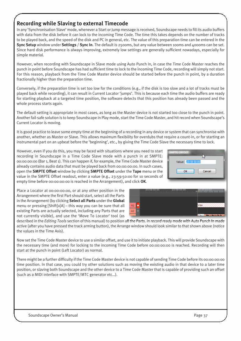
Recording while Slaving to external TimecodeIn any ‘Synchronisation Slave’ mode, whenever a Start or Jump message is received, Soundscape needs to fill its audio bufferswith data from the disk before it can lock to the incoming Time Code. The time this takes depends on the number of tracksto be played back, and the speed of the disk and PC in general, etc. The value of this preparation time can be entered in theSync Setup window under Settings / Sync In. The default is 2500ms, but any value between 100ms and 4000ms can be set.Since hard disk performance is always improving, extremely low settings are generally sufficient nowadays, especially forsimple material.
However, when recording with Soundscape in Slave mode using Auto Punch In, in case the Time Code Master reaches thepunch in point before Soundscape has had sufficient time to lock to the incoming Time Code, recording will simply not start.For this reason, playback from the Time Code Master device should be started before the punch in point, by a durationfractionally higher than the preparation time.
Conversely, if the preparation time is set too low for the conditions (e.g., if the disk is too slow and a lot of tracks must beplayed back while recording), it can result in Current Locator ‘jumps’. This is because each time the audio buffers are readyfor starting playback at a targeted time position, the software detects that this position has already been passed and thewhole process starts again.
The default setting is appropriate in most cases, as long as the Master device is not started too close to the punch in point.Another fail-safe solution is to keep Soundscape in Play mode, start the Time Code Master, and hit record when Soundscape’sCurrent Locator is moving.
It is good practice to leave some empty time at the beginning of a recording in any device or system that can synchronise withanother, whether as Master or Slave. This allows maximum flexibility for overdubs that require a count-in, or for starting aninstrumental part on an upbeat before the ‘beginning’, etc., by giving the Time Code Slave the necessary time to lock.
However, even if you do this, you may be faced with situations where you need to startrecording in Soundscape in a Time Code Slave mode with a punch in at SMPTE:00:00:00:00 (Bar 1, Beat 1). This can happen if, for example, the Time Code Master devicealready contains audio data that must be played back from 00:00:00:00. In such cases,open the SMPTE Offset window by clicking SMPTE Offset under the Tape menu or thevalue in the SMPTE Offset readout, enter a value (e.g., 23:59:50:00 for 10 seconds ofempty time before 00:00:00:00 is reached in the Arrangement), and click OK.
Place a Locator at 00:00:00:00, or at any other position in theArrangement where the first Part should start, select all the Partsin the Arrangement (by clicking Select all Parts under the Globalmenu or pressing [Shift]+[A] – this way you can be sure that allexisting Parts are actually selected, including any Parts that arenot currently visible), and use the ‘Move To Locator’ tool (asdescribed in the Editing Tools section of this manual) to position all the Parts. In record ready mode with Auto Punch In madeactive (after you have pressed the track arming button), the Arrange window should look similar to that shown above (noticethe values in the Time Axis).
Now set the Time Code Master device to use a similar offset, and use it to initiate playback. This will provide Soundscape withthe necessary time (and more) for locking to the incoming Time Code before 00:00:00:00 is reached. Recording will thenstart at the punch in point (Left Locator) as normal.
There might be a further difficulty if the Time Code Master device is not capable of sending Time Code before its 00:00:00:00time position. In that case, you could try other solutions such as moving the existing audio in that device to a later timeposition, or slaving both Soundscape and the other device to a Time Code Master that is capable of providing such an offset(such as a MIDI interface with SMPTE/MTC generator etc…).
Soundscape Owner’s Manual Page 37

Arrangement NavigationZoom OverviewThe zoom level for the Arrange window can becontrolled in several ways:
• with the four Zoom buttons
• with the Zoom Tool
• using key commands
• using the Context Sensitive Edit tool
• with an external Hardware Controllersupporting the MCU, HUI or JL Cooper CS/MCSProtocols via Console Manager.
Using the Zoom buttonsSoundscape provides a wide variety of different Zoom Levels in both horizontal and vertical directions. At the highest ZoomLevel, 1 Pixel on screen represents 1 Sample of the Audio file. Depending on the Display resolution, the Arrangement in thelowest Zoom Level can show several hours horizontally and all 256 Tracks vertically.
The waveform or automation data for each Part in the Arrange window is automatically displayed when the vertical andhorizontal zoom levels are sufficient to display anything sensible.
At the highest Zoom levels, the waveform data is extracted directly from the Take; In lower levels, the waveform datais read from a special Waveform Image File (.wvf extension) with a compressed resolution.
Horizontal ZoomIf the Current Locator is visible when zooming in horizontally, it is used as the centre of the zoom and remains in focus whilethe Arrangement ‘expands’ around it. Therefore, if you wish to zoom in on a particular point in the Arrangement, it can behelpful to place the Current Locator at or near that point.
If the Current Locator is not visible when zooming in horizontally, the visible centre of the Arrangement stays fixed whilezooming in.
It is often preferable to use the Zoom tool when accuracy is required. See the following page.
Vertical ZoomWhen zooming vertically, the top edge of the uppermost visible virtual track below the Time Axis stays fixed while theArrangement is zoomed in or out.
If you need to zoom in to edit a particular Part, it is helpful to make sure that this Part is shown on the top virtual track beforezooming in (this can be done by scrolling the window or moving the Part vertically).
Waveform ZoomRight-clicking the Vertical Zoom In/Out buttonszooms only the Waveform or Automation Curvesinside the Parts, increasing the vertical amplitudeof the audio waveforms and automation curves.This does not alter the audio or automation data,but allows you to see low level waveforms andautomation points, even in lower zoom levels.High amplitudes may be visually cut off at thetop.�
Verticle Zoom In
Verticle Zoom Out
Zoom Tool
Horizontal Zoom InHorizontal Zoom Out
Page 38 Soundscape Owner’s Manual

Zoom ToolClicking once on the Zoom Tool (or pressing the [Z] key) will turn the mouse pointer intoa magnifying glass when hovering over the Arrange Window. You can draw a rectanglein the Arrange window by holding down the left mouse button and dragging with the
mouse. Releasing the mouse button will zoom into the area selected. The mouse pointer will thenrevert to its previous shape and function.
It is also possible to zoom in directly to sample level with a single click at the required position inthe Arrange window (without drawing a rectangle). However this can be disconcerting, unless thezoom level is already very high. Coming from a low zoom level, it is impossible to reliably targetan area of, for example, 300 samples.
The Zoom Tool can also be used to zoom out by drawing a selection box that extends beyond thecurrent view of the Arrangement. The Arrange window will be scrolled automatically in the requireddirection, thus selecting a bigger section than currently visible.
Zooming using key commandsKey commands are also available for zooming:• Zoom In Vertical [Alt]+[Up Arrow]• Zoom Out Vertical [Alt]+[Down Arrow]• Zoom In Horizontal [Alt]+[Right Arrow]• Zoom Out Horizontal [Alt]+[Left Arrow]
Zoom and Position HistoryBy double clicking the Zoom Tool (or hitting [Z] twice) you can quickly return to the previous view, which includeshorizontal/vertical zoom level and horizontal/vertical position. This is an extremely useful way to switch between ProjectOverview and Track Detail View.
Soundscape remembers the last 8 views in the Arrange window, and their chronology. You can move either way through thisview sequence by using the left and right mouse buttons when double-clicking the Zoom Tool. The left button is used to viewprevious (less recent) views, the right button is used to return to next (more recent) views. (Alternatively, you can press 2x[Z]and [Shift] +2x [Z] keys instead.)
Views created using the Context Sensitive Edit tool are also remembered in the view sequence.
NOTE: If you move back to an earlier view in the view sequence and then use the Zoom Tool again, the next view insidethe sequence is replaced. For example if you go back to the fourth view and use the Zoom tool, the fifth view in thesequence is replaced by the new one.
Scrolling the Arrange windowThe Arrange window can be scrolled using the Scroll buttons in the usual Windows way. It can also be scrolled using thefollowing key commands: • Scroll Up [Ctrl]+[Alt]+[Up Arrow] • Scroll Down [Ctrl]+[Alt]+[Down Arrow]• Scroll Left [Ctrl]+[Alt]+[Left Arrow]• Scroll Right [Ctrl]+[Alt]+[Right Arrow]
Soundscape Owner’s Manual Page 39

Time AxisThe Time Axis, across the top of the Arrange window, shows time positionseither in bars, counts and ticks (960 per quarter note)
...or in SMPTE time as hours, minutes, seconds and frames
Toggling between the two types of time divisions can be done by selecting the corresponding option under the Settings / TimeAxis menu.
When working with musical time divisions at a low zoom level, only some bar numbers are shown. At a high zoom level, finertime subdivisions are shown, down to single ticks.
When working with SMPTE time divisions at a low zoom level, hours are shown. At a high zoom level, each single frame isvisible as a divider.
NOTE: The snap value can be set to quarter, 10th, or 100th frame, and at maximum zoom level with the Time Axis set toSMPTE time, the mouse position readout shows single samples for ultimate precision while editing.
Arrangement PartsParts represent blocks of audio or automation data used in the current Arrangement. Each Part plays back data from a Takestored on disk. A Part can represent the full information of a Take or just a section.
Data from a single Take can be used by any number of Parts at any point in the Arrangement without requiring any additionaldisk space; Editing Parts in the Arrangement (e.g., copying, cutting etc.) does not affect the corresponding Takes on disk.
Altering audio data by processing a Part (e.g., normalising, pitch shifting, or reversing it) will result in the creation of a newTake of the same length as the processed Part (the length may be different from the original if, for example, the Part is timestretched/compressed). Parts have individual parameters, such as start point in the Arrangement, start point in thecorresponding Take, and Length. Some of these parameters are specific to a Part type (e.g., only Audio Parts have a Start andEnd Part Volume setting), and all the Part parameters can be displayed and edited using the Info tool as described in theEditing Tools section in this chapter.
Most editing and processing operations which can be performed on a single Part, can also be performed on a group of selectedParts. You can, for instance, copy or move a group of Parts, make a cut across several Parts at the same position, or deleteseveral Parts at once.
Single or multiple Parts can be selected for editing by clicking in an empty spacein the Arrange window and dragging the mouse pointer to draw a ‘selectionbox’:
Any Part which is touched by the selection box will be selected and will turn greywhen the mouse button is released. The selection box can be started on a Partif the [Shift] key is held down while clicking (if the [Shift] key is not held down,clicking on a Part will trigger an editing or processing operation).
Page 40 Soundscape Owner’s Manual

When certain tools are assigned to the mouse button being used, no selection box can be drawn. These tools are: • Mixdown Tool• Multitrack Scrub Tool• Solo Scrub Tool• Solo Tool
However, holding down the [Shift] or [Ctrl] key allows Part selection even when one of these tools are assigned to the mousebutton.
If you need to draw a selection box beyond the currently visible section of the Arrangement, drag the outline of the selectionbox to any Arrange window border and the Arrangement will start to scroll.
A Part can be individually selected or deselected by clicking on it while holding down the [Ctrl] key on the computer keyboard.
Clicking in an empty space in the Arrange window, or performing an editing or processing operation on a non selected Part,will cancel all current Part selections.
The Keep Part selection item in Settings / Preferences / Arrangement determines whether the currently selected Part(s) willbe automatically deselected when an editing or processing operation has been performed. When a number of editing and/orprocessing operations need to be carried out on the same Parts, it is useful to tick this option in order to avoid having to repeatthe selection process over and over again.
Locators and MarkersLeft and Right Locators�The Left and Right Locators are used to define a target area for Auto Punch In/Out recording, looping and looprecording; They also affect the operation of certain editing tools (e.g., Mixdown tool, Crop tool...), are used bysome of the Global functions (as described in the Global Menu Section of the Menu Reference chapter), and areused as snap points for certain snap settings. They can also be used for automation snapshot recording, etc.
The time interval between the Locators is displayed in the L<<−−>>R Display inside the Status bar.
Setting the Left and Right LocatorsTo position the Left or Right Locator, click at the required position in the Time Axis with the corresponding mouse button. TheLocator will be set to the mouse position, or to the closest snap point if the Snap function is active. A Locator can also bemoved along the Time Axis by clicking and dragging its ‘handle’ with the corresponding mouse button.
While in play back or record, ‘on the fly’ positioning of the Locators is possible by using the [L] and [R] keys. In this case, thesnap setting is ignored.
Alternatively, you can click the Left or Right Locator Display inthe Tape Transport Bar to alter the time position in a dialoguebox. Depending on the Time Axis setting, SMPTE Time orBars/Beats/Ticks are displayed.
You can type [Space] instead of [.] or [:] and leading zeros arenot required. The time positions entered in the examples to theright will appear in the displays as 00017.01.000 and0024.01.000 .
Soundscape Owner’s Manual Page 41

Current LocatorThe Current Locator shows the current playback or Song Position the Arrangement.
Two Displays in the Tape Transport Bar show the Current Locator Position as song position inBars/Beats/Ticks and as SMPTE Time in Timecode Format.
The Current Locator can be positioned in several ways:• ..with the Tape Transport Buttons• ..by clicking or right-clicking in any empty section of the Arrange window. If a tool assignment is prohibitive (i.e. if the
Multitrack Scrub tool is selected), pressing the [Shift] key will allow positioning of the Current Locator. This is not possiblewhile in Play or Record mode.
• ..by clicking at the required position on the Time Axis while holding the [Shift] key. This is particularly useful when editingat a high zoom level and/or when there is no empty area visible in the Arrange window.
• ..by holding the [Shift] key and pressing the [Left Arrow] or [Right Arrow] key to move the Current Locator to the previousor next snap point (if the Snap function is active) or sample (if the Snap function is inactive).
• ..by holding the [Ctrl] key and pressing the [Left Arrow] or [Right Arrow] key to move the Current Locator to the previousor next Part beginning or end.�
• ..by clicking the button at the bottom of the left or Right Locator Display, to move the CurrentLocator to the current position of the corresponding Locator. This function is not available in Playmode or Record mode:
• ..by clicking the Song Position or SMPTE Time display in the Tape Transport Bar and entering a value in the dialoguebox. This function is not available in Play or Record mode.
Pressing the [C] key on the keyboard will centre the Current Locator inside the Arrange window.
It is also possible to keep the Current Locator in the centre of the screen during playback or recording (‘Tape Head’ View) byselecting Auto Scroll in the Settings / Preferences / Arrangement menu.
By default the screen is redrawn automatically to follow the Current Locator, whenever it reaches theright side of the Arrangement. This behaviour can be disabled by clicking the ‘Follow Current Locator’button located in the top right corner of the Arrange window (or by pressing the [J] key). The buttontoggles between a Play Icon (follow Current) and an illuminated Pause Icon (follow Current off).
Disabling ‘Follow Current Locator’ is especially useful while focussing on a particular edit point and working at a high zoomlevel.
MarkersThe Marker Bar runs under the Time Axis in the Arrange window andcan be shown or hidden using the View menu. You can insert up to999 named Markers per Arrangement. Markers are saved in theArrange file.
Marker DirectoryThe Marker Directory can be shown or hidden by ticking or untickingMarker Directory under the View menu, or by pressing the [W] key.The window to the right shows a text listing of Markers, with their IDnumber, name and time position in both SMPTE andbars/counts/ticks.
Page 42 Soundscape Owner’s Manual
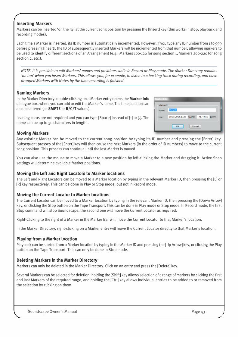
Inserting MarkersMarkers can be inserted ‘on the fly’ at the current song position by pressing the [Insert] key (this works in stop, playback andrecording modes).
Each time a Marker is inserted, its ID number is automatically incremented. However, if you type any ID number from 1 to 999before pressing [Insert], the ID of subsequently inserted Markers will be incremented from that number, allowing markers tobe used to identify different sections of an Arrangement (e.g., Markers 100-120 for song section 1, Markers 200-220 for songsection 2, etc.).
NOTE: It is possible to edit Markers’ names and positions while in Record or Play mode. The Marker Directory remains‘on top’ when you insert Markers. This allows you, for example, to listen to a backing track during recording, and havedropped Markers with Notes by the time recording is finished.
Naming MarkersIn the Marker Directory, double-clicking on a Marker entry opens the Marker Infodialogue box, where you can add or edit the Marker's name. The time position canalso be altered (as SMPTE or B/C/T values).
Leading zeros are not required and you can type [Space] instead of [:] or [.]. Thename can be up to 30 characters in length..
Moving MarkersAny existing Marker can be moved to the current song position by typing its ID number and pressing the [Enter] key.Subsequent presses of the [Enter] key will then cause the next Markers (in the order of ID numbers) to move to the currentsong position. This process can continue until the last Marker is moved.
You can also use the mouse to move a Marker to a new position by left-clicking the Marker and dragging it. Active Snapsettings will determine available Marker positions.
Moving the Left and Right Locators to Marker locationsThe Left and Right Locators can be moved to a Marker location by typing in the relevant Marker ID, then pressing the [L] or[R] key respectively. This can be done in Play or Stop mode, but not in Record mode.
Moving the Current Locator to Marker locationsThe Current Locator can be moved to a Marker location by typing in the relevant Marker ID, then pressing the [Down Arrow]key, or clicking the Stop button on the Tape Transport. This can be done in Play mode or Stop mode. In Record mode, the firstStop command will stop Soundscape, the second one will move the Current Locator as required.
Right-Clicking to the right of a Marker in the Marker Bar will move the Current Locator to that Marker’s location.
In the Marker Directory, right-clicking on a Marker entry will move the Current Locator directly to that Marker’s location.
Playing from a Marker locationPlayback can be started from a Marker location by typing in the Marker ID and pressing the [Up Arrow] key, or clicking the Playbutton on the Tape Transport. This can only be done in Stop mode.
Deleting Markers in the Marker DirectoryMarkers can only be deleted in the Marker Directory. Click on an entry and press the [Delete] key.
Several Markers can be selected for deletion: holding the [Shift] key allows selection of a range of markers by clicking the firstand last Markers of the required range, and holding the [Ctrl] key allows individual entries to be added to or removed fromthe selection by clicking on them.
Soundscape Owner’s Manual Page 43

Tape Transport BarThe Tape Transport Bar, located at the bottom of the main Soundscape Window, contains the above mentioned displays forLocator/Song Position, the Transport Section, and buttons for Auto Punch In/Out and Loop Playback/Record as well asdisplays for musical Time Signature (Sign), Tempo and SMPTE Offset.
�
To Beginning Click this button or press [Home] to move the Current Locator to the beginning of the first Part(s) in the Arrangement.
To EndClick this button or press [End] to move the Current Locator to the end of the last Part(s) in the Arrangement.
If you hold down the [Shift] key while clicking these buttons, the Current Locator will move to the previous or nextsnap point if the Snap function is active, or to the previous or next sample if the Snap function is inactive. This isparticularly useful when working with video and Snap set to Frames. This operation will interrupt playback orrecording.
If you hold down the [Ctrl] key while clicking these buttons, the Current Locator will move to the previous Partbeginning or next Part end. Using this function will interrupt playback or recording.
Rewind and Fast ForwardPress and hold these buttons to rewind or fast-forward the playhead – rewind and fast forward remain activeas long as the buttons are held. If pressed during Play mode, playback will resume as soon as the button isreleased. The [Left Arrow] and [Right Arrow ] keys duplicate these buttons.
NOTE: The speed of Rewind and Fast Forward can be increased by activating Fast REW / FF in Settings / Preferences/ General. In the same menu, Scrub during REW / FF can be activated, causing Reverse Play and Fast Forward to beperformed at twice the playback speed.
StopIf Soundscape is in Play or Record mode, clicking the Stop button (or [Down Arrow] key) once will stop playback orinterrupt the recording at the current song position.
Subsequent clicks on the Stop button will toggle the Current Locator between the Left Locator position and the startof the Arrangement. Clicking the Stop button after typing a Marker number on the numerical keypad positions theCurrent Locator to the corresponding Marker location.
Play / Repeat MemoryClicking the Play button (or [Up Arrow] key) will initiate playback from the current song position. Clicking the Playbutton after typing a Marker number on the numerical keypad initiates playback from the corresponding Markerlocation.
RecordClicking the Record button (or [NUM +] key) initiates recording from the current song position (if Auto Punch In andPre-Rolls are not active).
Recording can be started while Soundscape is stopped (in which case the Play button is also engaged automatically),or during playback (manual punch in), and can be stopped by clicking the Record button again, or the Play button(manual punch out). Clicking any other tape transport button also stops recording (and playback). If the Auto PunchOut function has been activated, recording stops when the Current Locator reaches the Right Locator.
NOTE: Recording behaviour depends on various settings (Auto Punch, Pre-/Post Roll, Loop Recording).
Page 44 Soundscape Owner’s Manual
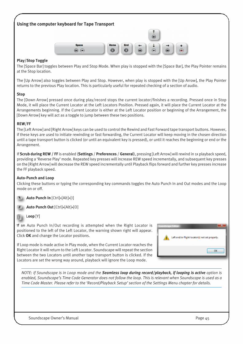
Using the computer keyboard for Tape Transport
Play/Stop ToggleThe [Space Bar] toggles between Play and Stop Mode. When play is stopped with the [Space Bar], the Play Pointer remainsat the Stop location.
The [Up Arrow] also toggles between Play and Stop. However, when play is stopped with the [Up Arrow], the Play Pointerreturns to the previous Play location. This is particularly useful for repeated checking of a section of audio.
StopThe [Down Arrow] pressed once during play/record stops the current locator/finishes a recording. Pressed once in StopMode, it will place the Current Locator at the Left Locators Position. Pressed again, it will place the Current Locator at theArrangements beginning. If the Current Locator is either at the Left Locator position or beginning of the Arrangement, the[Down Arrow] key will act as a toggle to jump between these two positions.
REW/FFThe [Left Arrow] and [Right Arrow] keys can be used to control the Rewind and Fast Forward tape transport buttons. However,if these keys are used to initiate rewinding or fast forwarding, the Current Locator will keep moving in the chosen directionuntil a tape transport button is clicked (or until an equivalent key is pressed), or until it reaches the beginning or end or theArrangement.
If Scrub during REW / FF is enabled (Settings / Preferences / General), pressing [Left Arrow] will rewind in 1x playback speed,providing a ‘Reverse Play’ mode. Repeated key presses will increase REW speed incrementally, and subsequent key presseson the [Right Arrow] will decrease the REW speed incrementally until Playback flips forward and further key presses increasethe FF playback speed.
Auto-Punch and LoopClicking these buttons or typing the corresponding key commands toggles the Auto Punch In and Out modes and the Loopmode on or off.
Auto Punch In [Ctrl]+[Alt]+[I]
Auto Punch Out [Ctrl]+[Alt]+[O]
Loop [Y]
If an Auto Punch In/Out recording is attempted when the Right Locator ispositioned to the left of the Left Locator, the warning shown right will appear.Click OK and change the Locator positions.
If Loop mode is made active in Play mode, when the Current Locator reaches theRight Locator it will return to the Left Locator. Soundscape will repeat the sectionbetween the two Locators until another tape transport button is clicked. If theLocators are set the wrong way around, playback will ignore the Loop mode.
NOTE: If Soundscape is in Loop mode and the Seamless loop during record/playback, if looping is active option isenabled, Soundscape’s Time Code Generator does not follow the loop. This is relevant when Soundscape is used as aTime Code Master. Please refer to the ‘Record/Playback Setup’ section of the Settings Menu chapter for details.
Soundscape Owner’s Manual Page 45

Time Signature and Tempo readoutsThe time signature and tempo readouts are located at the righthand side of the Tape Transport buttons. Clicking either ofthem opens a dialogue box in which the time signature (Sign)or Tempo can be entered.
When entering the time signature, the ‘beats per bar’ (first number) can be set to any value from 1 to 15 and the ‘beatvalue’ (second number) can be 4, 8 or 16. If you try to enter avalue outside these ranges, the closest available value will beused instead. Leading zeros are not required and you can type[Space] instead of [/].
The tempo can be set to any value between 30 and 240 beats per minute, with up to two decimal digits (e.g. 170.86 bpm).The leading zero (for a tempo under 100 bpm) is not required and you can type [Space] instead of [.].
The time signature and tempo in Soundscape is especially important while editing with musical Snap values or working inSync with a MIDI Sequencer. Note that changing time signature and tempo does not change the absolute time locations orPlayback speed of any part inside the Arrangement.
NOTE: The Time Signature and Tempo cannot be edited when a Tempo Map is loaded (see Menu Reference Chapter).
SMPTE OffsetClicking the SMPTE offset readout to the right of the Tape Transport calls up a dialogue box inwhich the required SMPTE offset value can be entered in SMPTE format. You can type [Space]instead of [:] and leading zeros are not required.
The SMPTE Offset can be used to align Soundscape correctly with time code from an externaldevice. For example, if a section of film which requires an audio track has time code startingat 00:18:23:06 (0 hours, 18 minutes, 23 seconds and 6 frames), entering this Offset value willmake the Arrangement also start at this time. In ‘Slave’ mode the Offset is subtracted fromthe external time code, and in ‘Master’ mode it is added to Soundscape’s timing before theMIDI Time Code is generated.
The Offset parameter can also be useful when it is necessary to record from time position 00:00:00:00 in ‘Slave’ mode. Pleaserefer to the Recording while slaving to Time Code subsection of this chapter for details.
Any value within the 24 hour range can be entered for SMPTE Offset.
Page 46 Soundscape Owner’s Manual
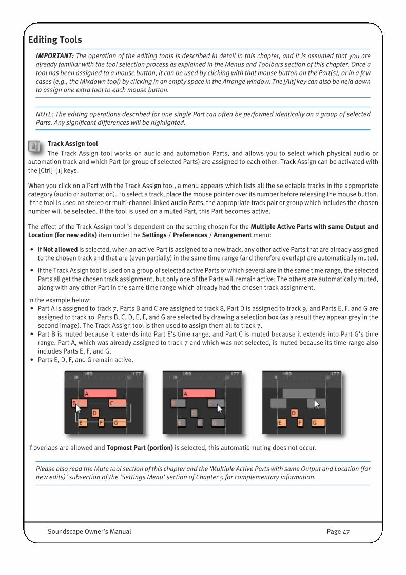
Editing Tools
IMPORTANT: The operation of the editing tools is described in detail in this chapter, and it is assumed that you arealready familiar with the tool selection process as explained in the Menus and Toolbars section of this chapter. Once atool has been assigned to a mouse button, it can be used by clicking with that mouse button on the Part(s), or in a fewcases (e.g., the Mixdown tool) by clicking in an empty space in the Arrange window. The [Alt] key can also be held downto assign one extra tool to each mouse button.
NOTE: The editing operations described for one single Part can often be performed identically on a group of selectedParts. Any significant differences will be highlighted.
Track Assign toolThe Track Assign tool works on audio and automation Parts, and allows you to select which physical audio or
automation track and which Part (or group of selected Parts) are assigned to each other. Track Assign can be activated withthe [Ctrl]+[1] keys.
When you click on a Part with the Track Assign tool, a menu appears which lists all the selectable tracks in the appropriatecategory (audio or automation). To select a track, place the mouse pointer over its number before releasing the mouse button.If the tool is used on stereo or multi-channel linked audio Parts, the appropriate track pair or group which includes the chosennumber will be selected. If the tool is used on a muted Part, this Part becomes active.
The effect of the Track Assign tool is dependent on the setting chosen for the Multiple Active Parts with same Output andLocation (for new edits) item under the Settings / Preferences / Arrangement menu:
• If Not allowed is selected, when an active Part is assigned to a new track, any other active Parts that are already assignedto the chosen track and that are (even partially) in the same time range (and therefore overlap) are automatically muted.
• If the Track Assign tool is used on a group of selected active Parts of which several are in the same time range, the selectedParts all get the chosen track assignment, but only one of the Parts will remain active; The others are automatically muted,along with any other Part in the same time range which already had the chosen track assignment.
In the example below:• Part A is assigned to track 7, Parts B and C are assigned to track 8, Part D is assigned to track 9, and Parts E, F, and G are
assigned to track 10. Parts B, C, D, E, F, and G are selected by drawing a selection box (as a result they appear grey in thesecond image). The Track Assign tool is then used to assign them all to track 7.
• Part B is muted because it extends into Part E's time range, and Part C is muted because it extends into Part G's timerange. Part A, which was already assigned to track 7 and which was not selected, is muted because its time range alsoincludes Parts E, F, and G.
• Parts E, D, F, and G remain active.
If overlaps are allowed and Topmost Part (portion) is selected, this automatic muting does not occur.
Please also read the Mute tool section of this chapter and the ‘Multiple Active Parts with same Output and Location (fornew edits)’ subsection of the ‘Settings Menu’ section of Chapter 5 for complementary information.
Soundscape Owner’s Manual Page 47
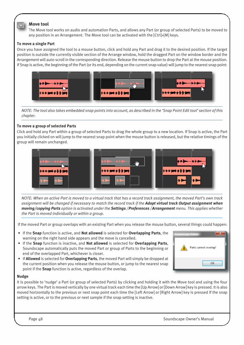
Move toolThe Move tool works on audio and automation Parts, and allows any Part (or group of selected Parts) to be moved toany position in an Arrangement. The Move tool can be activated with the [Ctrl]+[M] keys.
To move a single PartOnce you have assigned the tool to a mouse button, click and hold any Part and drag it to the desired position. If the targetposition is outside the currently visible section of the Arrange window, hold the dragged Part on the window border and theArrangement will auto-scroll in the corresponding direction. Release the mouse button to drop the Part at the mouse position.If Snap is active, the beginning of the Part (or its end, depending on the current snap value) will jump to the nearest snap point:
NOTE: The tool also takes embedded snap points into account, as described in the ‘Snap Point Edit tool’ section of thischapter.
To move a group of selected PartsClick and hold any Part within a group of selected Parts to drag the whole group to a new location. If Snap is active, the Partyou initially clicked on will jump to the nearest snap point when the mouse button is released, but the relative timings of thegroup will remain unchanged.
NOTE: When an active Part is moved to a virtual track that has a record track assignment, the moved Part’s own trackassignment will be changed if necessary to match the record track if the Adopt virtual track Output assignment whenmoving/copying Parts option is activated under the Settings / Preferences / Arrangement menu. This applies whetherthe Part is moved individually or within a group.
If the moved Part or group overlaps with an existing Part when you release the mouse button, several things could happen:
• If the Snap function is active, and Not allowed is selected for Overlapping Parts, thewarning on the right hand side appears and the move is cancelled.
• If the Snap function is inactive, and Not allowed is selected for Overlapping Parts,Soundscape automatically puts the moved Part or group of Parts to the beginning orend of the overlapped Part, whichever is closer.
• If Allowed is selected for Overlapping Parts, the moved Part will simply be dropped atthe current position when you release the mouse button, or jump to the nearest snappoint if the Snap function is active, regardless of the overlap.
NudgeIt is possible to ‘nudge’ a Part (or group of selected Parts) by clicking and holding it with the Move tool and using the fourarrow keys. The Part is moved vertically by one virtual track each time the [Up Arrow] or [Down Arrow] key is pressed. It is alsomoved horizontally to the previous or next snap point each time the [Left Arrow] or [Right Arrow] key is pressed If the snapsetting is active, or to the previous or next sample if the snap setting is inactive.
Page 48 Soundscape Owner’s Manual

Copy toolThe Copy tool works on audio and automation Parts and allows any Part (or group of selected Parts) to be copied to
any position in the Arrange window. The operation of the Copy tool is similar to that of the Move tool, except that the originalPart or group will be left unchanged. The copied Part or group will be identical to the original and reference the same Take,so no additional Disk space is required for the copy. The Copy tool can be activated with the [Ctrl]+[C] keys.
Nudge copyThe copy of a Part can be ‘nudged’ while the original stays in place, using the Copy tool and the four arrow keys in the mannerdescribed for the Move tool above.
Move & Copy Vertical toolsThese tools works on audio and automation Parts. They only allow edits in the vertical direction (i.e., from one
virtual track to another). This ensures that no change in timing occurs. These can be activated with [Ctrl]+[Shift]+[M] or[Ctrl]+[Shift]+[C].
Cut toolThe Cut tool works on audio and automation Parts, and allows non-destructive editing of any Part in the Arrange
window. To cut a Part, click on it at the time position where the edit is required. If Snap is active, the position of the cut willcorrespond to the nearest snap point. The resulting two Parts will have identical volume, fade, and track assignment settings(although any existing fade curve across the two Parts will be displayed and remain active until you use the Fade In, Fade Out,or Volume And Fade Trim tool on one of the Parts).
The resulting new Parts can then be treated in exactly the same way as any other Parts, and can be copied or moved. Forexample, the Cut tool is useful for defining a region that requires a different volume or fade setting.
You can make cuts across several virtual tracks at once by selecting a group, and then clicking on one Part in the group. Anyother selected Parts at the same timing position will be cut at the same point.
For precise editing, it is often necessary to deactivate Snap and zoom in to waveform level.For instance, to remove a click from a Part, the waveform can be cut at the start and endof the click, and the new Part that contains the click can then be deleted, have its volumereduced, or be muted (as illustrated right).
The Cut tool can be activated with the [Ctrl]+[X] keys.
NOTE: You can also cut several selected Parts at the same time by clicking on one of them at the time position wherethe edit is required.
Move To, Copy To & Cut At Locator toolsThe Move to-, Copy to-, and Cut at-Nearest Locator tools work on audio and automation Parts, and allow
Locator-based editing. The Current Locator, Left Locator or Right Locator (whichever the mouse pointer is closest to) determinethe position of a Move, Copy, or Cut operation. With the Move tool or Copy tool, the beginning or end of the selected Part(s)will snap to the nearest Locator. This allows, for instance, sound effects to start or end at a time code reference which is setwhile playing, or by entering the Locator Position as a value in a Tape Transport bar readout.
These tools can be activated with the [Ctrl]+[Alt]+[M], [Ctrl]+[Alt]+[C] and [Ctrl]+[Alt]+[X] keys.
Soundscape Owner’s Manual Page 49
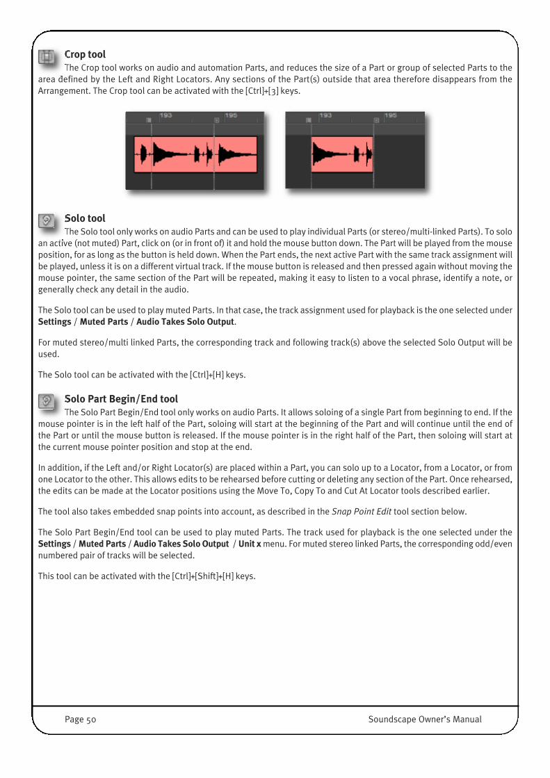
Crop toolThe Crop tool works on audio and automation Parts, and reduces the size of a Part or group of selected Parts to the
area defined by the Left and Right Locators. Any sections of the Part(s) outside that area therefore disappears from theArrangement. The Crop tool can be activated with the [Ctrl]+[3] keys.
Solo toolThe Solo tool only works on audio Parts and can be used to play individual Parts (or stereo/multi-linked Parts). To solo
an active (not muted) Part, click on (or in front of) it and hold the mouse button down. The Part will be played from the mouseposition, for as long as the button is held down. When the Part ends, the next active Part with the same track assignment willbe played, unless it is on a different virtual track. If the mouse button is released and then pressed again without moving themouse pointer, the same section of the Part will be repeated, making it easy to listen to a vocal phrase, identify a note, orgenerally check any detail in the audio.
The Solo tool can be used to play muted Parts. In that case, the track assignment used for playback is the one selected underSettings / Muted Parts / Audio Takes Solo Output.
For muted stereo/multi linked Parts, the corresponding track and following track(s) above the selected Solo Output will beused.
The Solo tool can be activated with the [Ctrl]+[H] keys.
Solo Part Begin/End toolThe Solo Part Begin/End tool only works on audio Parts. It allows soloing of a single Part from beginning to end. If the
mouse pointer is in the left half of the Part, soloing will start at the beginning of the Part and will continue until the end ofthe Part or until the mouse button is released. If the mouse pointer is in the right half of the Part, then soloing will start atthe current mouse pointer position and stop at the end.
In addition, if the Left and/or Right Locator(s) are placed within a Part, you can solo up to a Locator, from a Locator, or fromone Locator to the other. This allows edits to be rehearsed before cutting or deleting any section of the Part. Once rehearsed,the edits can be made at the Locator positions using the Move To, Copy To and Cut At Locator tools described earlier.
The tool also takes embedded snap points into account, as described in the Snap Point Edit tool section below.
The Solo Part Begin/End tool can be used to play muted Parts. The track used for playback is the one selected under theSettings / Muted Parts / Audio Takes Solo Output / Unit x menu. For muted stereo linked Parts, the corresponding odd/evennumbered pair of tracks will be selected.
This tool can be activated with the [Ctrl]+[Shift]+[H] keys.
Page 50 Soundscape Owner’s Manual

Snap Point Edit toolThis tool works on audio and automation Parts. Clicking an audio or automation Part with The Snap Point Edit tool will
embed a snap point within that Part, at the time position where the mouse pointer is located (or at the nearest snap point ifSnap is active). [Ctrl]+[Shift]+[D] also activates this function. The embedded snap point appears as a dotted line across thePart:
Clicking on a Part which already contains a snap point will move that snap point to the new position (or to the nearest snappoint if Snap is active).
Double-clicking a Part which already contains a snap point will delete that snap point.
Typically, an embedded snap point would be used to mark a point in an audio Take or automation curve which needs to bepositioned precisely, e.g., on a particular frame when working with video, or on a particular beat when editing music.
• If Snap is active, when a Part that contains a snap point is edited using the Move, Move to Locator, Copy, or Copy toLocator tool, that embedded snap point (rather than the Part’s beginning) responds to the external snap points definedby the current snap setting. The embedded snap point is also taken into account when the Move selected Parts to Llocator or Copy selected Parts to L locator function in the Global menu is used.
• If Snap is active and set to Part or Prt+Mrk+L, any snap point embedded in a Part (as well as its beginning and end)affects edits to other Parts performed using the Move, Copy, or Trim tools (if these edits are ‘within range’).
The Solo Part Begin/End tool will also respond to an embedded snap point, treating it as a Part beginning or Locator to startplayback from, or like a Part End or Locator to stop at, according to the position of the mouse pointer.
The position of an embedded snap point can be checked or edited in the PartInfo window, which is opened by clicking the Part with the Info tool. The snappoint’s position is displayed in SMPTE time and B/C/T counted from the Part’sbeginning.
When editing the value using the computer keyboard, leading zeros are not required, and you can type [Space] instead of [:]or [.].
NOTE: The embedded snap point is not saved with the Take but only with the Part in the Arrangement. Therefore, thesame Take can be used by several Parts, with different snap point locations, in any number of Arrangements.
Audio Part Snap Point Automation Part Snap Point
Soundscape Owner’s Manual Page 51

Scrub toolsThese tools works on audio and automation Parts. The Solo (white) and Multitrack (grey) Scrub tools allow the
audio to be played forwards or backwards, using the mouse to determine the playback speed and direction. These tools arealso available using [Ctrl]+[B] and [Ctrl]+[Shift]+[B].
With the Solo Scrub tool selected, holding the mouse button down on an audioPart (or pair of stereo/multi-channel linked Parts) will cause the mouse pointerto change to a scrub icon.
The scrub icon consists of two opposing white arrows and a center line. Whenthe Current Locator is moving, the arrow which points in the opposite directionto playback becomes transparent. Initially, the Current Locator will be alignedwith the scrub icon’s centre line. Dragging the mouse in either direction will trigger playback in that direction.
The selection made under the Settings / Preferences / Arrangement / Scrub tools behaviour menu determines how theScrub tools react to further mouse movements:
• If Locator based scrub is selected, the distance between the scrub icon and the Current Locator determines the scrubbingspeed, from zero up to normal speed. Scrubbing slows down as the Current Locator nears the scrub icon, and stops whenit becomes aligned with the scrub icon’s center line.
• If Speed based scrub is selected, the initial scrubbing speed is determined by the speed at which the Scrub tool is firstmoved. Further mouse movements in the same direction increase the scrubbing speed (which can exceed normal speed).Mouse movements in the opposite direction pull the Current Locator back, decreasing the scrubbing speed or changingthe scrubbing direction.
NOTE: In both cases, a higher zoom level allows slower scrubbing speeds.
When the end of the Part is reached, the next active Part with the same track assignment will be scrubbed, unless it is on adifferent virtual track and Topmost Part (portion) is played is selected for the Multiple Active Parts with same Output andLocation option (Settings / Preferences / Arrangement).
The Multitrack Scrub tool works in the same way as the Solo Scrub tool, except that it scrubs all active Parts. It is not necessaryto point at a particular Part for playback to occur.
The Solo Scrub tool can be used to scrub muted Parts. In this case, the track used for playback is the one defined for soloingmuted Parts (Settings / Muted Parts / Audio Takes Solo Output).
NOTE: You can drop the Left and Right Locators while scrubbing, using the [L] and [R] keys.
Part Volume and Fade toolsThese tools only work on audio Parts. Each Part in the Arrangement has a beginning volume, an end
volume, and one of eight possible fade curve settings, and there are four tools which are used to edit these parameters. Thisprovides an extremely powerful and flexible alternative to mix automation. If the Show Part Volumes option is enabled(Settings / Preferences / Arrangement), Part volume is indicated on-screen by the vertical amplitude of the coloured sectionof a Part. However, due to screen resolutions, volumes are only displayed from the third vertical zoom level on.
Page 52 Soundscape Owner’s Manual

Volume & Fade Edit tool Select the tool and click on an audio Part. The Volume & Fade Edit windowwill appear (Also activated using [Ctrl]+[V]):
The faders for beginning volume and end volume can be linked by checking thebox between the two faders. In this way, the overall level can be changed withoutaffecting the volume contour. When linked, the difference in dB between thevolume settings is maintained. However, because the faders follow an audio taperlaw for dB versus on-screen movement, the distance between the faders on-screen will not remain constant as the faders are moved.
To edit the beginning volume or end volume individually, ensure that the checkbox between the faders is not selected.
You can select a fader either by clicking on it or using the [Tab] or [Shift]+[Tab]key(s). The selected fader will flash and can be moved either by clicking anddragging it with the mouse, or using the arrow keys (for a slow/fine level change),or using the [Page Up]/[Page Down] keys (for a fast/coarse level change). Whenusing the arrow keys, [Left Arrow] and [Right Arrow] can function as [Up Arrow]and [Down Arrow] respectively.
The two check boxes, Update prev Part end volume and Update next Part beginvolume, can be used if there is an adjacent Part before or after the edited Partand on the same virtual track. If a box is checked, the beginning or end volume ofthe corresponding Part will be automatically adjusted to match the volume of the edited Part, ensuring a smooth overallvolume contour. Either check box will be dimmed if there is no corresponding adjacent Part.
NOTE: The check box settings are not saved for each Part, but remain as you leave them each time you use the tool.
There are 8 different fade curves providing one linear, one cosine, three exponential, and three logarithmic shapes. Eachcurve can be used for fading in or out. The currently selected curve setting is shown in black, and clicking on another curvewill select it in blue, showing that a change has been made. The curves apply to a fade from one level to another, as well asto a fade in from silence (-96dB) or a fade out into silence.
NOTES:A linear fade curve has the effect that it reduces volume by a fixed amount per second. This means that after half of thefade time, the level is half of the original (-6dB). After 3/4 of the fade time, the level is 1/4 of the original (-12dB), etc.This means that the rest of the fade (to -96dB) takes place in the last 1/4 of the time. This is a linear fade and has thecharacteristic that the level decreases very fast towards the end of the fade. An exponential fade, where the fade rateis faster at the start and more gentle towards the end of the fade will produce a more natural sounding fade out. The maximum fade time for one single Part is 3 min 10 sec 05 frames (at 44100Hz). For fades longer than this, cut thePart into several smaller ones, select them all, and use the Fade In/Out tools, or use the global feature within the Volumetool to define a fade across all Parts.
Fade In & Fade Out toolsThe Fade In and Fade Out tools change the beginning volume to -96dB or the end volume to -96dB respectively
without affecting the other volume setting. The curve setting is left unchanged. They are also available via [Ctrl]+[E] and[Ctrl]+[F]
If you click with either Fade tool on a Part which already has a fade selected, the fade will be removed, and the value ofwhichever volume was highest will be applied to both. This is also the case when multiple Parts are selected, so that turningoff the fade for multiple Parts will set all Part volumes to the highest volume found for all selected Parts. In other words, youwill lose any volume contours that may have been previously defined!
Soundscape Owner’s Manual Page 53
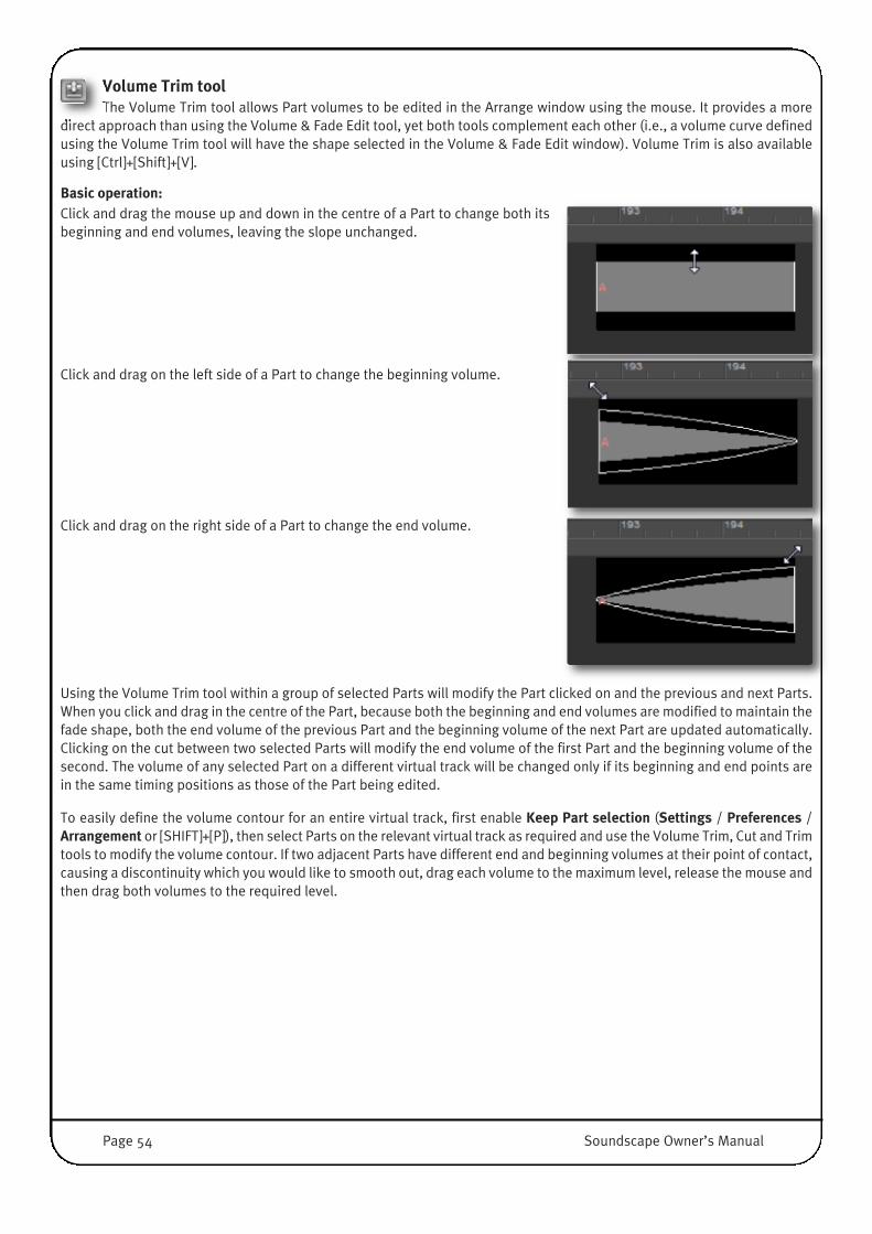
Volume Trim toolThe Volume Trim tool allows Part volumes to be edited in the Arrange window using the mouse. It provides a more
direct approach than using the Volume & Fade Edit tool, yet both tools complement each other (i.e., a volume curve definedusing the Volume Trim tool will have the shape selected in the Volume & Fade Edit window). Volume Trim is also availableusing [Ctrl]+[Shift]+[V].
Basic operation:Click and drag the mouse up and down in the centre of a Part to change both itsbeginning and end volumes, leaving the slope unchanged.
Click and drag on the left side of a Part to change the beginning volume.
Click and drag on the right side of a Part to change the end volume.
Using the Volume Trim tool within a group of selected Parts will modify the Part clicked on and the previous and next Parts.When you click and drag in the centre of the Part, because both the beginning and end volumes are modified to maintain thefade shape, both the end volume of the previous Part and the beginning volume of the next Part are updated automatically.Clicking on the cut between two selected Parts will modify the end volume of the first Part and the beginning volume of thesecond. The volume of any selected Part on a different virtual track will be changed only if its beginning and end points arein the same timing positions as those of the Part being edited.
To easily define the volume contour for an entire virtual track, first enable Keep Part selection (Settings / Preferences /Arrangement or [SHIFT]+[P]), then select Parts on the relevant virtual track as required and use the Volume Trim, Cut and Trimtools to modify the volume contour. If two adjacent Parts have different end and beginning volumes at their point of contact,causing a discontinuity which you would like to smooth out, drag each volume to the maximum level, release the mouse andthen drag both volumes to the required level.
Page 54 Soundscape Owner’s Manual

Part Volume & Fades for multiple PartsThe four Volume and Fade tools can also be used if multiple Parts are selected, across one or severalvirtual tracks. The following paragraphs describe Volume and Fade tool operation in such circumstances.
Volume & Fade Edit windowWith multiple Parts selected, the beginning and end volumes shown when using the Volume & Fade Edit tool are the beginningvolume of the first selected Part and the end volume of the last selected Part, for the virtual track of the Part that you clickon. This allows a group of Parts to be treated as one if required, with one curve and two volume settings.
• If the Global fade per Virtual Track box is not checked: Changes made to any parameter will be made for all selectedParts. For example, if the end volume is increased by 5dB, all Parts will have their end volume setting increased by 5dB.If the fade curve shape is changed, then all Parts will have the same fade curve shape selected.
• If the Global fade per Virtual Track box is checked: If the fade curve shape is changed, a smooth fade will be made acrossall selected Parts on each virtual track, starting at the beginning volume level and finishing at the end volume level,approximated to the chosen curve (shown in black). Each individual Part will then have this curve selected, allowing acloser overall approximation to the curve by selecting all the Parts again, using the Volume & Fade Edit tool, then turningoff the global check box and selecting the linear curve.
If you use the Volume & Fade Edit tool for a group of Parts which have different curves, then the curve will not be shown inblack, and you will not be able to alter beginning and end volumes separately; The box linking the faders is automaticallychecked and it cannot be unchecked. However, If you select a new fade curve shape, you will be allowed to use the fader linkand Global fade per Virtual Track check box settings if desired. Note that all Parts will then have their curve set the same.
Changing the overall level for multiple PartsIf you want to change the overall level of a track which has contours already defined, use the Volume & Fade Edit tool, makingsure that the Global fade per Virtual Track check box is unchecked and that the fader link box is checked so that the samechanges are made to both beginning and end volumes of all selected Parts.
Alternatively, you can use the Part Info tool and click on one of the selected Parts which does allow the necessary level changeto be made. Link the faders and change the level as required. All Parts will have their beginning and end volumes changedby the same amount.
NOTE: If some selected Parts have levels that are already too close to minimum or maximum for the same amount ofchange to be made, these will saturate at minimum or maximum volume. Sometimes the faders cannot be movedenough in the required direction, maybe because the beginning volume of the first Part is at minimum (e.g., a fade in)and the end volume of the last Part is also at minimum (e.g., a fade out). In this instance, both faders would be at -96dBand so the level of the track could not be reduced by, say, 6dB. The easy way to get around this is to select all requiredParts except the fades in/out at either end. Make sure that the Update prev/next Part end/begin volume boxes arechecked, and change the level. You can also use this technique to increase the level when there is a fade at either end,because the fade in and fade out will still be from -96dB.
Fading multiple PartsWhen you use the Fade In or Fade Out tool to fade across multiple Parts, each Part will take on the curve setting of the Partthat you click on. Also, the shape for the entire fade will approximate to that curve so that the beginning and end volumes ofeach Part are selected automatically, according to points on the curve.
However, unless the edited Part has the linear curve shape selected first, the approximation to the overall shape required maynot be as regular as expected, because the overall result will be, by definition, a succession of non-linear curves. To changethe curve setting of each Part to linear, first select all the Parts, then use the Volume & Fade Edit tool and select the linearcurve in the Volume & Fade Edit window, making sure that the global fade per virtual track box is unchecked.
Soundscape Owner’s Manual Page 55

Normalize Process toolThis tool only works on audio Parts. Normalising can be used to adjust the overall level of a Part or the level of a whole
Take so that its peak matches a value of your choice. This process is used typically to boost a signal which was not recordedat a sufficient level. A new Take is generated to disk and renamed automatically (e.g., #1 or #2 is appended to the originalTake’s name). This tool can also be accessed via [Ctrl]+[N].
First, select a Part or group of Parts, and click with the Normalise tool.
If you have selected any Part which is not the entire length of theTake on the Disk, or which references a Take also referenced byother Parts which you did not select, the message shown right willbe displayed.
Click No to generate a new normalised Take just for the Part(s)selected, i.e., the same length as the Part(s). Click Yes tonormalise the entire Take and generate a new Take which is thesame length as the original.
The Part(s) will then be scanned, and the highest peak value found for all selected Parts will bereported as shown right.
If you wish to continue with the normalise process, enter the required value for the new peaklevel and click OK, otherwise click Cancel to leave everything unaltered. Remember to includea minus sign when entering the value; Any positive value will be treated as 0dB.
If you go ahead, each selected Part will be increased in level by anamount which causes the reported peak level to reach the valueyou entered.
TIP: You can use the Normalise function to determine noise gate ‘on level’ settings: Make a cut at each end of an areathat you wish to ‘gate out’, then click on the resulting Part with the Normalise tool. It will show you the peak leveldetected for the selected Part. Click Cancel to avoid normalising the Part, then glue the cut section back into the mainPart. If you use the Normalise value as the ‘off level’ value for the noise gate, it will mute all sections of the Part belowthat level.
Time Stretch/Compress Process toolThe Time Stretch/Compress Process tool ([Ctrl]+[Shift]+[T]) only works on one mono Part or stereo/multichannel linked
group at a time. It is used to change the duration of a Part (or stereo/multichannel linked group) without altering the pitch,within a range from 67% up to 150%. The length of the generated Take(s) can be specified in percentage, SMPTE, B/C/T orTempo.
Pitch Shift Process toolThe Pitch Shift Process tool ([Ctrl]+[Shift]+[P]) only works on one mono Part or stereo/multichannel linked group at a
time. It is used to change the pitch of a Part (or stereo/multichannel linked group) without altering its length, within a rangefrom 67% up to 150%. The pitch of the generated Take(s) can be specified in percentage, or semitones and cents change.
Page 56 Soundscape Owner’s Manual
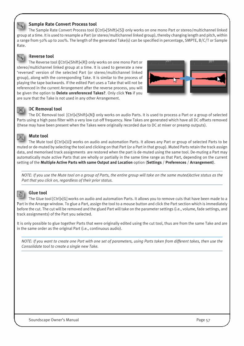
Sample Rate Convert Process toolThe Sample Rate Convert Process tool ([Ctrl]+[Shift]+[S]) only works on one mono Part or stereo/multichannel linked
group at a time. It is used to resample a Part (or stereo/multichannel linked group), thereby changing length and pitch, withina range from 50% up to 200%. The length of the generated Take(s) can be specified in percentage, SMPTE, B/C/T or SampleRate.
Reverse toolThe Reverse tool ([Ctrl]+[Shift]+[R]) only works on one mono Part or
stereo/multichannel linked group at a time. It is used to generate a new‘reversed’ version of the selected Part (or stereo/multichannel linkedgroup), along with the corresponding Take. It is similar to the process ofplaying the tape backwards. If the edited Part uses a Take that will not bereferenced in the current Arrangement after the reverse process, you willbe given the option to Delete unreferenced Takes?. Only click Yes if youare sure that the Take is not used in any other Arrangement.
DC Removal toolThe DC Removal tool [Ctrl]+[Shift]+[N]) only works on audio Parts. It is used to process a Part or a group of selected
Parts using a high pass filter with a very low cut-off frequency. New Takes are generated which have all DC offsets removed(these may have been present when the Takes were originally recorded due to DC at mixer or preamp outputs).
Mute toolThe Mute tool ([Ctrl]+[U]) works on audio and automation Parts. It allows any Part or group of selected Parts to be
muted or de-muted by selecting the tool and clicking on that Part (or a Part in that group). Muted Parts retain the track assigndata, and memorised track assignments are restored when the part is de-muted using the same tool. De-muting a Part mayautomatically mute active Parts that are wholly or partially in the same time range as that Part, depending on the currentsetting of the Multiple Active Parts with same Output and Location option (Settings / Preferences / Arrangement).
NOTE: If you use the Mute tool on a group of Parts, the entire group will take on the same muted/active status as thePart that you click on, regardless of their prior status.
Glue toolThe Glue tool [Ctrl]+[G] works on audio and automation Parts. It allows you to remove cuts that have been made to a
Part in the Arrange window. To glue a Part, assign the tool to a mouse button and click the Part section which is immediatelybefore the cut. The cut will be removed and the glued Part will take on the parameter settings (i.e., volume, fade settings, andtrack assignments) of the Part you selected.
It is only possible to glue together Parts that were originally edited using the cut tool, thus are from the same Take and arein the same order as the original Part (i.e., continuous audio).
NOTE: If you want to create one Part with one set of parameters, using Parts taken from different takes, then use theConsolidate tool to create a single new Take.
Soundscape Owner’s Manual Page 57

Mixdown toolThe Mixdown tool ([Ctrl]+[Shift]+[Y]) allows all active tracks to be digitally mixed together to create a new mono, stereo
or multichannel Take, so that sub mixes or a complete stereo mix can be performed without leaving the digital domain. TheMixdown process does not introduce any extra background noise or degradation of the audio quality, and includes the effectof the volume, fade and mixer settings and automation associated with the original Parts. Mixdowns are performed in real-time, so that the result includes all the EQ, real-time FX (i.e., plug-ins), volume and pan settings, automation data for theactive Parts, and audio from external mixer inputs.
The Mixdown tool can only operate if enough physical tracks are available for the required destination format (mono, stereoor multichannel).
To Create a Mixdown, first position the Left and Right Locators ateither end of the region you wish to mix. The length of the new Takeis determined by the Left and Right Locators, so place themaccurately to avoid using more disk space than you require.
Once you are happy with the volume, pan, fade settings and anyplug-in settings and automation data, select the Mixdown tool andclick between the Left and Right Locators, on the virtual track whereyou want the mixdown Parts to be positioned.
A menu will appear requiring you to select the mixdown format, andthe output or bus to be used as the recording input. The outputselection is critical, as only tracks routed to the selected outputswill be mixed down.
For example, you may have tracks 1 to 4 routed to busses 1-2, andtracks 5 to 8 routed to busses 3-4 in your Mixer. If so, selecting Bus1-2 will only mix down tracks 1 to 4.
It is therefore a good idea to bus all of your tracks to a Master mixer column so they are all available from one output selection.You can then control which tracks will be mixed by selecting or muting them in the Arrange window.
See the Mixer section of this manual for more information.
Remember, you will not get any sound without an active Mixer!
Releasing the mouse button will initiate the mixdown. The lowest numbered track or track group which is not already assignedwithin the area defined by the Locators will automatically be selected for recording the mixdown to.
The dialogue box shown to the right will appear, showing the mix’s progress. You will alsohear the audio that has been selected.
The new Take(s) and Part(s) will be named Mixdown, with L and R extensions in the caseof a stereo mixdown, along with a number if there are previous mixdowns in the selectedfolder.
Page 58 Soundscape Owner’s Manual
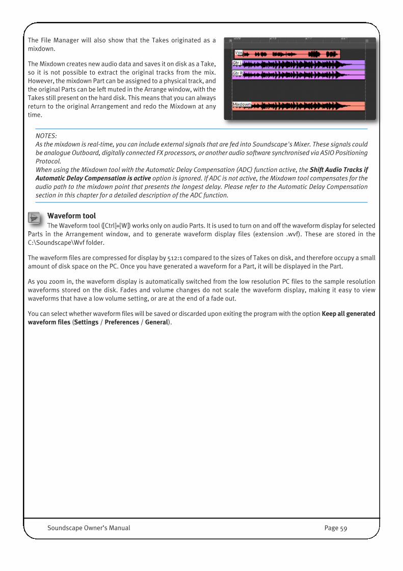
The File Manager will also show that the Takes originated as amixdown.
The Mixdown creates new audio data and saves it on disk as a Take,so it is not possible to extract the original tracks from the mix.However, the mixdown Part can be assigned to a physical track, andthe original Parts can be left muted in the Arrange window, with theTakes still present on the hard disk. This means that you can alwaysreturn to the original Arrangement and redo the Mixdown at anytime.
NOTES: As the mixdown is real-time, you can include external signals that are fed into Soundscape's Mixer. These signals couldbe analogue Outboard, digitally connected FX processors, or another audio software synchronised via ASIO PositioningProtocol.When using the Mixdown tool with the Automatic Delay Compensation (ADC) function active, the Shift Audio Tracks ifAutomatic Delay Compensation is active option is ignored. If ADC is not active, the Mixdown tool compensates for theaudio path to the mixdown point that presents the longest delay. Please refer to the Automatic Delay Compensationsection in this chapter for a detailed description of the ADC function.
Waveform toolThe Waveform tool ([Ctrl]+[W]) works only on audio Parts. It is used to turn on and off the waveform display for selected
Parts in the Arrangement window, and to generate waveform display files (extension .wvf). These are stored in theC:\Soundscape\Wvf folder.
The waveform files are compressed for display by 512:1 compared to the sizes of Takes on disk, and therefore occupy a smallamount of disk space on the PC. Once you have generated a waveform for a Part, it will be displayed in the Part.
As you zoom in, the waveform display is automatically switched from the low resolution PC files to the sample resolutionwaveforms stored on the disk. Fades and volume changes do not scale the waveform display, making it easy to viewwaveforms that have a low volume setting, or are at the end of a fade out.
You can select whether waveform files will be saved or discarded upon exiting the program with the option Keep all generatedwaveform files (Settings / Preferences / General).
Soundscape Owner’s Manual Page 59
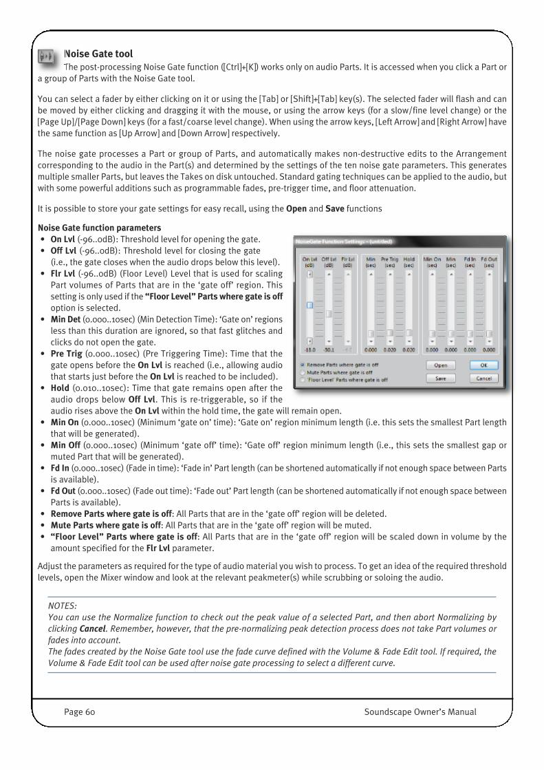
Noise Gate toolThe post-processing Noise Gate function ([Ctrl]+[K]) works only on audio Parts. It is accessed when you click a Part or
a group of Parts with the Noise Gate tool.
You can select a fader by either clicking on it or using the [Tab] or [Shift]+[Tab] key(s). The selected fader will flash and canbe moved by either clicking and dragging it with the mouse, or using the arrow keys (for a slow/fine level change) or the[Page Up]/[Page Down] keys (for a fast/coarse level change). When using the arrow keys, [Left Arrow] and [Right Arrow] havethe same function as [Up Arrow] and [Down Arrow] respectively.
The noise gate processes a Part or group of Parts, and automatically makes non-destructive edits to the Arrangementcorresponding to the audio in the Part(s) and determined by the settings of the ten noise gate parameters. This generatesmultiple smaller Parts, but leaves the Takes on disk untouched. Standard gating techniques can be applied to the audio, butwith some powerful additions such as programmable fades, pre-trigger time, and floor attenuation.
It is possible to store your gate settings for easy recall, using the Open and Save functions
Noise Gate function parameters• On Lvl (-96..0dB): Threshold level for opening the gate.• Off Lvl (-96..0dB): Threshold level for closing the gate
(i.e., the gate closes when the audio drops below this level).• Flr Lvl (-96..0dB) (Floor Level) Level that is used for scaling
Part volumes of Parts that are in the ‘gate off’ region. Thissetting is only used if the “Floor Level” Parts where gate is offoption is selected.
• Min Det (0.000..10sec) (Min Detection Time): ‘Gate on’ regionsless than this duration are ignored, so that fast glitches andclicks do not open the gate.
• Pre Trig (0.000..10sec) (Pre Triggering Time): Time that thegate opens before the On Lvl is reached (i.e., allowing audiothat starts just before the On Lvl is reached to be included).
• Hold (0.010..10sec): Time that gate remains open after theaudio drops below Off Lvl. This is re-triggerable, so if theaudio rises above the On Lvl within the hold time, the gate will remain open.
• Min On (0.000..10sec) (Minimum ‘gate on’ time): ‘Gate on’ region minimum length (i.e. this sets the smallest Part lengththat will be generated).
• Min Off (0.000..10sec) (Minimum ‘gate off’ time): ‘Gate off’ region minimum length (i.e., this sets the smallest gap ormuted Part that will be generated).
• Fd In (0.000..10sec) (Fade in time): ‘Fade in’ Part length (can be shortened automatically if not enough space between Partsis available).
• Fd Out (0.000..10sec) (Fade out time): ‘Fade out’ Part length (can be shortened automatically if not enough space betweenParts is available).
• Remove Parts where gate is off: All Parts that are in the ‘gate off’ region will be deleted.• Mute Parts where gate is off: All Parts that are in the ‘gate off’ region will be muted. • “Floor Level” Parts where gate is off: All Parts that are in the ‘gate off’ region will be scaled down in volume by the
amount specified for the Flr Lvl parameter.
Adjust the parameters as required for the type of audio material you wish to process. To get an idea of the required thresholdlevels, open the Mixer window and look at the relevant peakmeter(s) while scrubbing or soloing the audio.
NOTES: You can use the Normalize function to check out the peak value of a selected Part, and then abort Normalizing byclicking Cancel. Remember, however, that the pre-normalizing peak detection process does not take Part volumes orfades into account.The fades created by the Noise Gate tool use the fade curve defined with the Volume & Fade Edit tool. If required, theVolume & Fade Edit tool can be used after noise gate processing to select a different curve.
Page 60 Soundscape Owner’s Manual
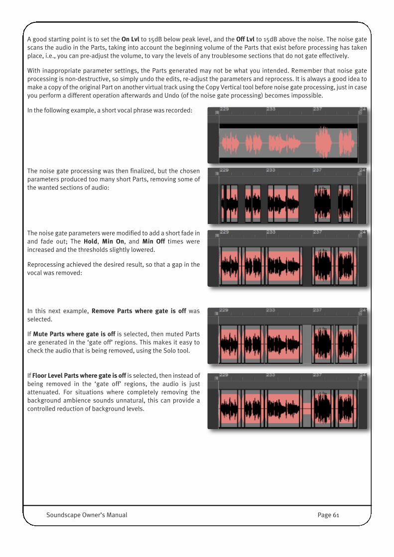
A good starting point is to set the On Lvl to 15dB below peak level, and the Off Lvl to 15dB above the noise. The noise gatescans the audio in the Parts, taking into account the beginning volume of the Parts that exist before processing has takenplace, i.e., you can pre-adjust the volume, to vary the levels of any troublesome sections that do not gate effectively.
With inappropriate parameter settings, the Parts generated may not be what you intended. Remember that noise gateprocessing is non-destructive, so simply undo the edits, re-adjust the parameters and reprocess. It is always a good idea tomake a copy of the original Part on another virtual track using the Copy Vertical tool before noise gate processing, just in caseyou perform a different operation afterwards and Undo (of the noise gate processing) becomes impossible.
In the following example, a short vocal phrase was recorded:
The noise gate processing was then finalized, but the chosenparameters produced too many short Parts, removing some ofthe wanted sections of audio:
The noise gate parameters were modified to add a short fade inand fade out; The Hold, Min On, and Min Off times wereincreased and the thresholds slightly lowered.
Reprocessing achieved the desired result, so that a gap in thevocal was removed:
In this next example, Remove Parts where gate is off wasselected.
If Mute Parts where gate is off is selected, then muted Partsare generated in the ‘gate off’ regions. This makes it easy tocheck the audio that is being removed, using the Solo tool.
If Floor Level Parts where gate is off is selected, then instead ofbeing removed in the ‘gate off’ regions, the audio is justattenuated. For situations where completely removing thebackground ambience sounds unnatural, this can provide acontrolled reduction of background levels.
Soundscape Owner’s Manual Page 61

Info tool The Info tool ([Ctrl]+[I]) works on Audio and Automation Parts. It is used to view or edit information about a Part or Take.It allows naming of Parts and Takes, and precise editing of all Part parameters.
Audio PartsTo view Part information, select the tool and click on an individual Part. The Part Info dialogue box will be displayed:
Here you can enter a name for the Part and Take, move the Part to a new starttime, edit the Part length, change output assignments, assign fade curves, adjustbeginning and end volumes, invert the phase, set the timelock status, check thePart’s layer assignment and select which audio Take the Part will use.
• If the Update all other selected Parts name box is checked, the edited namewill replace the current name of all the selected Parts when OK is clicked.
• If the Auto append speaker ext. if Multi-Channel linked box is checked, anappropriate extension will be added to the name of all selected Stereo-Linkedor Multi-Channel linked Parts. For Multi-Channel linked Parts, the extensionmay be ‘numeric’ or ‘surround’ (e.g. L, C, R or S), depending on the setting ofthe Multi-Channel speaker name extension option under the Settings /Preferences / General menu.
• If the Update Take(s) Name box is checked, the name of the Takes referencedby the selected Part(s) will be updated when OK is clicked.
Clicking the Select Take(s) button will select the Take referenced by the Part inthe File Manager. Please note that this may change the current folder selection.The Select Take(s) button is dimmed if several Parts are selected which referenceTakes located in different folders (as they cannot be selected simultaneously).
The start position in the Arrangement, the length, and the start position in theTake can also be entered in bars/counts/ticks, or in SMPTE + sample extension,allowing sample accurate positioning.
If multiple Parts are selected, the Part Info window shows the values for the Part that was clicked. The amount of changeentered for any parameter is applied for all other selected Parts where possible. For example, if the Part length is reduced by1 frame, all other selected Parts also have their length reduced by 1 frame. The only exceptions to this are when the sameamount of change to the Start in Arr, Length, or Start in Take values cannot be made for other selected Parts (because ofoverlaps, Part/Take lengths, etc.). The maximum amount of change that can successfully be made to all selected Parts issubstituted. A way of checking that the values entered are applicable to all Parts is to click on another parameter after enteringchanges – If the changed value remains as you have entered it, then the change is possible for all selected Parts; If not, thenthe value represents the maximum allowable change.
Changes to the Take assignment are not allowed when multiple Parts are selected, including stereo linked Parts. Changes tothe Output, Timelock, Fade and Invert Phase settings are only applied to the Part that was clicked.
Automation PartsThe Info tool works in a similar manner on Automation parts, though the available parameters are different, according to thenature of the Part. The Fade, Volume and Phase parameters are absent, while a Display parameter is added, whichdetermines what type of automation data is shown in the Part (the Automation Curve Select tool, described in the ‘MixerAutomation’ section of this manual, can also be used for that purpose).
Page 62 Soundscape Owner’s Manual

Consolidate Process toolThe Consolidate Process tool ([Ctrl]+[Shift]+[G]) only works on audio Parts. It is used to create new Takes by combining
the audio referenced by selected Parts that are located on the same virtual track and assigned to the same physical track.One new Take is created for each physical track.
The audio data included in the new Takes reflects the Part volume information, fades and crossfades that were applied to theselected Parts. Any silent sections between the selected Parts are also included in the new Takes.
After the new Takes have been generated, the selected Parts in the Arrangement are edited in such a way that they referencethe new Takes, and so that overlaps, fades, crossfades and silences are removed, always resulting in the smallest possiblenumber of Parts.
Optionally, the process also offers an option to delete selected muted Parts when present.
Any processed Parts which become muted are automatically deleted.
WARNING: The Takes generated by the Consolidation process only include the audio data that is actually used by theselected Parts. If the original Takes referenced by these Parts contain valuable audio data that is not used by the Partsin the current Arrangement, please note that this audio may be deleted after processing, depending on the optionselected under Settings / Preferences / Arrangement / Audio Processing tools behaviour / Audio Takes that becomeunused after processing.
In this example, Parts A, C, D and F are assigned to track 9. PartE is also assigned to track 9 but is muted. Part B is assigned totrack 16.
Parts A, B, C, D, E and F are selected for consolidation:
Because the selection includes a muted Part, the dialogue boxshown right is displayed after clicking one of the selected Parts.Clicking Yes or No triggers the processing; Clicking Cancel abortsthe operation.
Clicking Yes allows Part E to be removed from the Arrangement,resulting in only three parts being selected. Parts C, D and F arecombined to create an new Take which is referenced by Parts A#01 and C #01. Part B is also replaced by a new Part B #01, whichreferences a new Take.
Clicking No allows the muted Part E to remain in the Arrangement.
A further dialogue box may be displayed, depending on theoption selected under Settings / Preferences / Arrangement /Audio Processing tools behaviour / Audio Takes that becomeunused after processing. The available options are described inthe Settings Menu chapter.
Soundscape Owner’s Manual Page 63

Delete toolThe Delete tool ([Ctrl]+[D]) works on Audio and Automation Parts.
Click on a Part or group of selected Parts to delete it. If Takes are left on therecord/process folder which have become unreferenced in the currentArrangement, a dialogue box will be displayed (shown right).
If you no longer require these Takes, and you are sure that they are not used by anyother Arrangement, click Yes and the Takes will be deleted from disk. Click No if youwant to save them, or if you are not sure whether they are used elsewhere.
NOTE: When a Part or group of Parts has been selected, you can simply use the [Delete] key instead of the Delete tool.
Stereo Link toolThe Stereo Link tool ([Ctrl]+[L]) only works on audio Parts. It allows two Parts to be linked for all editing operations,including soloing.
To stereo-link two Parts, select them then click either of them. If the target Parts are surrounded by other Parts of identicallength and start position on adjacent virtual tracks, click on the uppermost targeted Part.
Stereo linking can only take place if the two Parts are on adjacent virtual tracks,have identical lengths and start positions in the Arrangement, and reside on thesame Layer. If this is not the case, a dialogue box appears warning that the linkingcould not be completed.
Multiple Parts may be selected, but only those fulfillingthe above criteria will be stereo linked. Linked Partsappear as shown to the right, still with the original trackassignments and colours. Using the Track Assign toolon stereo linked Parts will assign tracks in odd-evenpairs (i.e., 1-2, 3-4, etc.).
The same tool can be used to undo the stereo linkbetween two Parts – Just click either of the linked Partsand they become independent again.
NOTE: If you use the Stereo Link tool on a group of Parts, the entire group will take on the same link status as the Partthat you click on, regardless of each Part’s prior status.
�
Two Mono Parts Stereo-linked Part
Page 64 Soundscape Owner’s Manual

Multi-Channel Link Part toolThe Multi-Channel Link Part tool ([Ctrl]+[4]) only works on audio Parts. It
allows multiple Parts to be linked for all editing operations, including soloing.To multi-channel link Parts, select them then click one of them. Multi-channellinking can only take place if the Parts are on adjacent virtual tracks, haveidentical lengths and start positions in the Arrangement, and reside on thesame Layer. If this is not the case, a dialogue box appears, warning that thelinking cannot be completed.
Multiple Parts may be selected, but only those fulfillingthe above criteria will be multi-channel linked. Anylinked Parts appear as shown on the right side, still withthe original track assignments and colours. Using theTrack Assign tool on multi-channel linked Parts willassign tracks in series (i.e., 1-2-3, 3-4-5, etc.).
The same tool can be used to undo the multi-channellink between Parts – Just click either of the linked Partsand they become independent again.
NOTE: If you use the Multi-Channel Link tool on a group of Parts, the entire group will take on the same link status asthe Part that you click on, regardless of each Part’s prior status.
Trim Tool (Exclude Adjacent Parts Unless Selected)This tool, also accessed using the [Ctrl]+[T] keys, works on Audio and Automation Parts. It allows the start or end of a
Part or group of selected Parts to be dragged to the left or right using the mouse, thus shortening or lengthening the Part(s).The audio or automation data remains in the same timing position, allowing you to ‘reveal’ more or less of the data from theTake.
To trim a Part, click on its beginningor end, hold the mouse button downand drag with the mouse in therequired direction.
You can also move the position of acut between two Parts (e.g., whenyou have cut a Part in two with a fadeinto the second section).
The tool always allows you to draw aselection box across a cut, to selectthe Parts on both sides.
Dragging the cut will lengthen one Part and shorten the other.
You can trim Parts from multiple tracks at the same time, as long as the beginnings/ends/cuts are at identical time positions.
Independent Parts Multiple Linked Parts
Soundscape Owner’s Manual Page 65
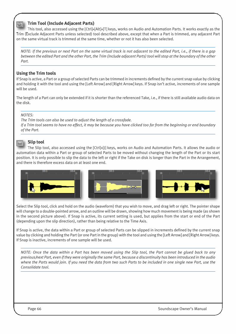
Trim Tool (Include Adjacent Parts)This tool, also accessed using the [Ctrl]+[Alt]+[T] keys, works on Audio and Automation Parts. It works exactly as the
Trim (Exclude Adjacent Parts unless selected) tool described above, except that when a Part is trimmed, any adjacent Parton the same virtual track is trimmed at the same time, whether or not it has also been selected.
NOTE: If the previous or next Part on the same virtual track is not adjacent to the edited Part, i.e., if there is a gapbetween the edited Part and the other Part, the Trim (Include adjacent Parts) tool will stop at the boundary of the otherPart.
Using the Trim toolsIf Snap is active, a Part or a group of selected Parts can be trimmed in increments defined by the current snap value by clickingand holding it with the tool and using the [Left Arrow] and [Right Arrow] keys. If Snap isn’t active, increments of one samplewill be used.
The length of a Part can only be extended if it is shorter than the referenced Take, i.e., if there is still available audio data onthe disk.
NOTES: The Trim tools can also be used to adjust the length of a crossfade.If a Trim tool seems to have no effect, it may be because you have clicked too far from the beginning or end boundaryof the Part.
Slip toolThe Slip tool, also accessed using the [Ctrl]+[J] keys, works on Audio and Automation Parts. It allows the audio or
automation data within a Part or group of selected Parts to be moved without changing the length of the Part or its startposition. It is only possible to slip the data to the left or right if the Take on disk is longer than the Part in the Arrangement,and there is therefore excess data on at least one end.
Select the Slip tool, click and hold on the audio (waveform) that you wish to move, and drag left or right. The pointer shapewill change to a double-pointed arrow, and an outline will be drawn, showing how much movement is being made (as shownin the second picture above). If Snap is active, its current setting is used, but applies from the start or end of the Part(depending upon the slip direction), rather than being relative to the Time Axis.
If Snap is active, the data within a Part or group of selected Parts can be slipped in increments defined by the current snapvalue by clicking and holding the Part (or one Part in the group) with the tool and using the [Left Arrow] and [Right Arrow] keys.If Snap is inactive, increments of one sample will be used.
NOTE: Once the data within a Part has been moved using the Slip tool, the Part cannot be glued back to anyprevious/next Part, even if they were originally the same Part, because a discontinuity has been introduced in the audiowhere the Parts would join. If you need the data from two such Parts to be included in one single new Part, use theConsolidate tool.
�
Page 66 Soundscape Owner’s Manual
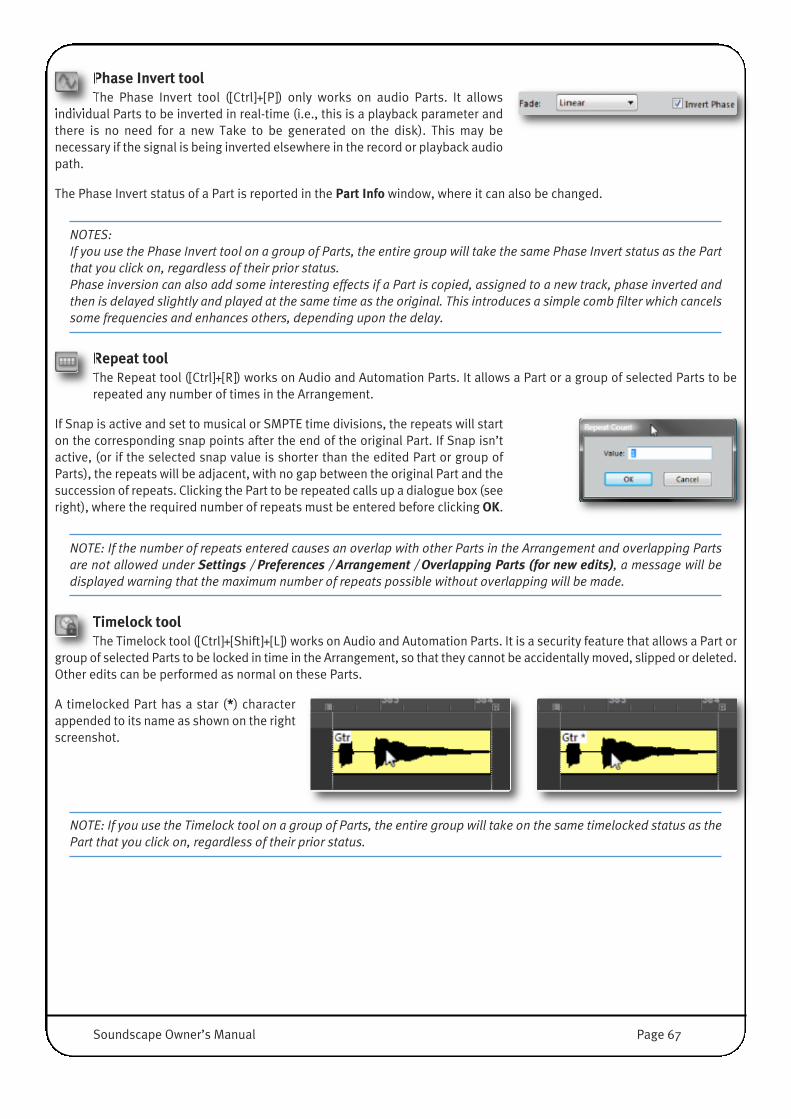
Phase Invert tool The Phase Invert tool ([Ctrl]+[P]) only works on audio Parts. It allows
individual Parts to be inverted in real-time (i.e., this is a playback parameter andthere is no need for a new Take to be generated on the disk). This may benecessary if the signal is being inverted elsewhere in the record or playback audiopath.
The Phase Invert status of a Part is reported in the Part Info window, where it can also be changed.
NOTES: If you use the Phase Invert tool on a group of Parts, the entire group will take the same Phase Invert status as the Partthat you click on, regardless of their prior status.Phase inversion can also add some interesting effects if a Part is copied, assigned to a new track, phase inverted andthen is delayed slightly and played at the same time as the original. This introduces a simple comb filter which cancelssome frequencies and enhances others, depending upon the delay.
Repeat toolThe Repeat tool ([Ctrl]+[R]) works on Audio and Automation Parts. It allows a Part or a group of selected Parts to berepeated any number of times in the Arrangement.
If Snap is active and set to musical or SMPTE time divisions, the repeats will starton the corresponding snap points after the end of the original Part. If Snap isn’tactive, (or if the selected snap value is shorter than the edited Part or group ofParts), the repeats will be adjacent, with no gap between the original Part and thesuccession of repeats. Clicking the Part to be repeated calls up a dialogue box (seeright), where the required number of repeats must be entered before clicking OK.
NOTE: If the number of repeats entered causes an overlap with other Parts in the Arrangement and overlapping Partsare not allowed under Settings / Preferences / Arrangement / Overlapping Parts (for new edits), a message will bedisplayed warning that the maximum number of repeats possible without overlapping will be made.
Timelock toolThe Timelock tool ([Ctrl]+[Shift]+[L]) works on Audio and Automation Parts. It is a security feature that allows a Part or
group of selected Parts to be locked in time in the Arrangement, so that they cannot be accidentally moved, slipped or deleted.Other edits can be performed as normal on these Parts.
A timelocked Part has a star (*) characterappended to its name as shown on the rightscreenshot.
NOTE: If you use the Timelock tool on a group of Parts, the entire group will take on the same timelocked status as thePart that you click on, regardless of their prior status.
Soundscape Owner’s Manual Page 67
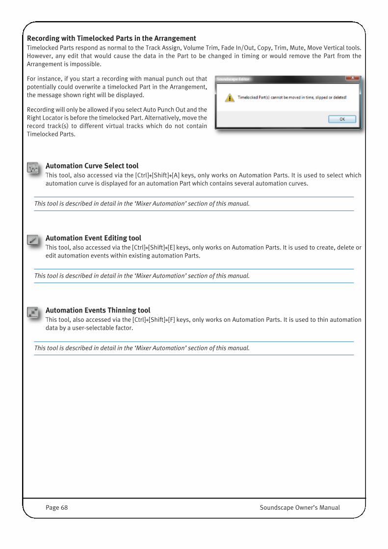
Recording with Timelocked Parts in the Arrangement�Timelocked Parts respond as normal to the Track Assign, Volume Trim, Fade In/Out, Copy, Trim, Mute, Move Vertical tools.However, any edit that would cause the data in the Part to be changed in timing or would remove the Part from theArrangement is impossible.
For instance, if you start a recording with manual punch out thatpotentially could overwrite a timelocked Part in the Arrangement,the message shown right will be displayed.
Recording will only be allowed if you select Auto Punch Out and theRight Locator is before the timelocked Part. Alternatively, move therecord track(s) to different virtual tracks which do not containTimelocked Parts.
Automation Curve Select toolThis tool, also accessed via the [Ctrl]+[Shift]+[A] keys, only works on Automation Parts. It is used to select whichautomation curve is displayed for an automation Part which contains several automation curves.
This tool is described in detail in the ‘Mixer Automation’ section of this manual.
Automation Event Editing toolThis tool, also accessed via the [Ctrl]+[Shift]+[E] keys, only works on Automation Parts. It is used to create, delete oredit automation events within existing automation Parts.
This tool is described in detail in the ‘Mixer Automation’ section of this manual.
Automation Events Thinning toolThis tool, also accessed via the [Ctrl]+[Shift]+[F] keys, only works on Automation Parts. It is used to thin automationdata by a user-selectable factor.
This tool is described in detail in the ‘Mixer Automation’ section of this manual.
Page 68 Soundscape Owner’s Manual
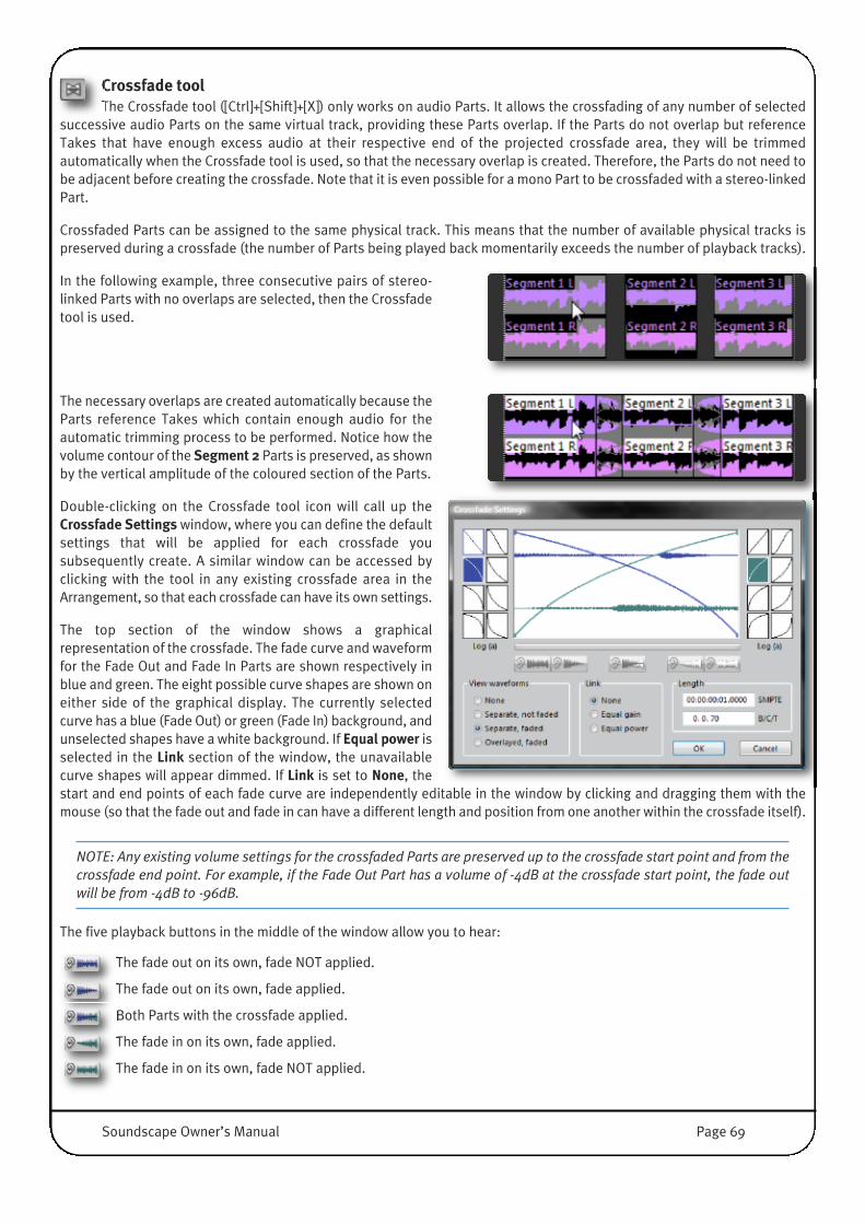
Crossfade toolThe Crossfade tool ([Ctrl]+[Shift]+[X]) only works on audio Parts. It allows the crossfading of any number of selected
successive audio Parts on the same virtual track, providing these Parts overlap. If the Parts do not overlap but referenceTakes that have enough excess audio at their respective end of the projected crossfade area, they will be trimmedautomatically when the Crossfade tool is used, so that the necessary overlap is created. Therefore, the Parts do not need tobe adjacent before creating the crossfade. Note that it is even possible for a mono Part to be crossfaded with a stereo-linkedPart.
Crossfaded Parts can be assigned to the same physical track. This means that the number of available physical tracks ispreserved during a crossfade (the number of Parts being played back momentarily exceeds the number of playback tracks).
In the following example, three consecutive pairs of stereo-linked Parts with no overlaps are selected, then the Crossfadetool is used.
The necessary overlaps are created automatically because theParts reference Takes which contain enough audio for theautomatic trimming process to be performed. Notice how thevolume contour of the Segment 2 Parts is preserved, as shownby the vertical amplitude of the coloured section of the Parts.
Double-clicking on the Crossfade tool icon will call up theCrossfade Settings window, where you can define the defaultsettings that will be applied for each crossfade yousubsequently create. A similar window can be accessed byclicking with the tool in any existing crossfade area in theArrangement, so that each crossfade can have its own settings.
The top section of the window shows a graphicalrepresentation of the crossfade. The fade curve and waveformfor the Fade Out and Fade In Parts are shown respectively inblue and green. The eight possible curve shapes are shown oneither side of the graphical display. The currently selectedcurve has a blue (Fade Out) or green (Fade In) background, andunselected shapes have a white background. If Equal power isselected in the Link section of the window, the unavailablecurve shapes will appear dimmed. If Link is set to None, thestart and end points of each fade curve are independently editable in the window by clicking and dragging them with themouse (so that the fade out and fade in can have a different length and position from one another within the crossfade itself).
NOTE: Any existing volume settings for the crossfaded Parts are preserved up to the crossfade start point and from thecrossfade end point. For example, if the Fade Out Part has a volume of -4dB at the crossfade start point, the fade outwill be from -4dB to -96dB.
The five playback buttons in the middle of the window allow you to hear:
The fade out on its own, fade NOT applied.
The fade out on its own, fade applied.
Both Parts with the crossfade applied.
The fade in on its own, fade applied.
The fade in on its own, fade NOT applied.
Soundscape Owner’s Manual Page 69
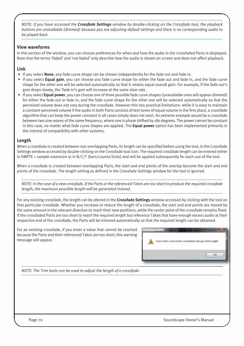
NOTE: If you have accessed the Crossfade Settings window by double-clicking on the Crossfade tool, the playbackbuttons are unavailable (dimmed) because you are adjusting default settings and there is no corresponding audio tobe played back.
View waveformsIn this section of the window, you can choose preferences for when and how the audio in the crossfaded Parts is displayed.Note that the terms ‘faded’ and ‘not faded’ only describe how the audio is shown on screen and does not affect playback.
Link• If you select None, any fade curve shape can be chosen independently for the fade out and fade in.• If you select Equal gain, you can choose any fade curve shape for either the fade out and fade in, and the fade curve
shape for the other one will be selected automatically so that it retains equal overall gain. For example, if the fade out’sgain drops slowly, the ‘fade in’s gain will increase at the same slow rate.
• If you select Equal power, you can choose one of three possible fade curve shapes (unavailable ones will appear dimmed)for either the fade out or fade in, and the fade curve shape for the other one will be selected automatically so that theperceived volume does not vary during the crossfade. However this has practical limitations: while it is easy to maintaina constant perceived volume if the audio in both Parts consists of test tones of equal volume in the first place, a crossfadealgorithm that can keep the power constant in all cases simply does not exist. An extreme example would be a crossfadebetween two sine waves of the same frequency, where one is phase shifted by 180 degrees. The power cannot be constantin this case, no matter what fade curve shapes are applied. The Equal power option has been implemented primarily inthe interest of compatibility with other systems.
LengthWhen a crossfade is created between non overlapping Parts, its length can be specified before using the tool, in the CrossfadeSettings window accessed by double-clicking on the Crossfade tool icon. The required crossfade length can be entered eitherin SMPTE + sample extension or in B/C/T (bars/counts/ticks) and will be applied subsequently for each use of the tool.
When a crossfade is created between overlapping Parts, the start and end points of the overlap become the start and endpoints of the crossfade. The length setting as defined in the Crossfade Settings window for the tool is ignored.
NOTE: In the case of a new crossfade, If the Parts or the referenced Takes are too short to produce the required crossfadelength, the maximum possible length will be generated instead.
For any existing crossfade, the length can be altered in the Crossfade Settings window accessed by clicking with the tool onthat particular crossfade. Whether you increase or reduce the length of a crossfade, the start and end points are moved bythe same amount in the relevant direction to reach their new positions, while the center point of the crossfade remains fixed.If the crossfaded Parts are too short to reach the required length but reference Takes that have enough excess audio at theirrespective end of the crossfade, the Parts will be trimmed automatically so that the required length can be obtained.
For an existing crossfade, if you enter a value that cannot be reachedbecause the Parts and their referenced Takes are too short, this warningmessage will appear.
NOTE: The Trim tools can be used to adjust the length of a crossfade.
Page 70 Soundscape Owner’s Manual
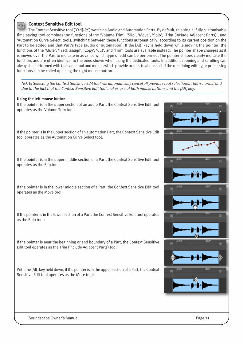
Context Sensitive Edit toolThe Context Sensitive tool ([Ctrl]+[2]) works on Audio and Automation Parts. By default, this single, fully customisable
time-saving tool combines the functions of the ‘Volume Trim’, ‘Slip’, ‘Move’, ‘Solo’, ‘Trim (Include Adjacent Parts)’, and‘Automation Curve Select’ tools, switching between these functions automatically, according to its current position on thePart to be edited and that Part’s type (audio or automation). If the [Alt] key is held down while moving the pointer, thefunctions of the ‘Mute’, ‘Track assign’, ‘Copy’, ‘Cut’, and ‘Trim’ tools are available instead. The pointer shape changes as itis moved over the Part to indicate in advance which type of edit can be performed. The pointer shapes clearly indicate thefunction, and are often identical to the ones shown when using the dedicated tools. In addition, zooming and scrolling canalways be performed with the same tool and menus which provide access to almost all of the remaining editing or processingfunctions can be called up using the right mouse button.
NOTE: Selecting the Context Sensitive Edit tool will automatically cancel all previous tool selections. This is normal anddue to the fact that the Context Sensitive Edit tool makes use of both mouse buttons and the [Alt] key.
Using the left mouse button�If the pointer is in the upper section of an audio Part, the Context Sensitive Edit tooloperates as the Volume Trim tool.
If the pointer is in the upper section of an automation Part, the Context Sensitive Edittool operates as the Automation Curve Select tool.
If the pointer is in the upper middle section of a Part, the Context Sensitive Edit tooloperates as the Slip tool.
If the pointer is in the lower middle section of a Part, the Context Sensitive Edit tooloperates as the Move tool:
If the pointer is in the lower section of a Part, the Context Sensitive Edit tool operatesas the Solo tool:
If the pointer is near the beginning or end boundary of a Part, the Context SensitiveEdit tool operates as the Trim (Include Adjacent Parts) tool:
With the [Alt] key held down, if the pointer is in the upper section of a Part, the ContextSensitive Edit tool operates as the Mute tool:
Soundscape Owner’s Manual Page 71
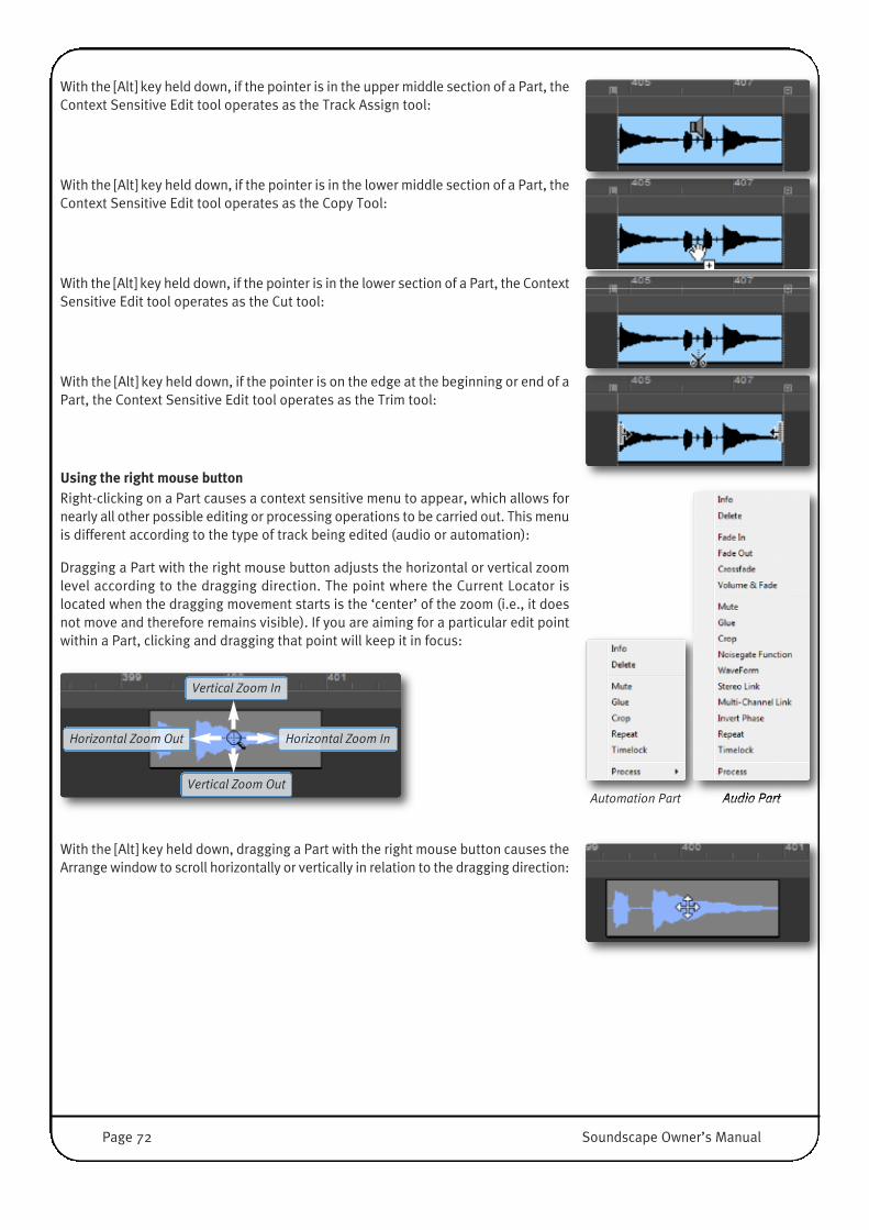
With the [Alt] key held down, if the pointer is in the upper middle section of a Part, theContext Sensitive Edit tool operates as the Track Assign tool:
With the [Alt] key held down, if the pointer is in the lower middle section of a Part, theContext Sensitive Edit tool operates as the Copy Tool:
With the [Alt] key held down, if the pointer is in the lower section of a Part, the ContextSensitive Edit tool operates as the Cut tool:
With the [Alt] key held down, if the pointer is on the edge at the beginning or end of aPart, the Context Sensitive Edit tool operates as the Trim tool:
Using the right mouse buttonRight-clicking on a Part causes a context sensitive menu to appear, which allows fornearly all other possible editing or processing operations to be carried out. This menuis different according to the type of track being edited (audio or automation):
Dragging a Part with the right mouse button adjusts the horizontal or vertical zoomlevel according to the dragging direction. The point where the Current Locator islocated when the dragging movement starts is the ‘center’ of the zoom (i.e., it doesnot move and therefore remains visible). If you are aiming for a particular edit pointwithin a Part, clicking and dragging that point will keep it in focus:
With the [Alt] key held down, dragging a Part with the right mouse button causes theArrange window to scroll horizontally or vertically in relation to the dragging direction:
Vertical Zoom In
Vertical Zoom Out
Horizontal Zoom InHorizontal Zoom Out
Automation Part Audio Part
Page 72 Soundscape Owner’s Manual

Customising the Context Sensitive Edit toolOnce you have got to grips with the Context Sensitive Edit tool,you may want to customise its operation to suit yourpreferences. This can be done easily: double-clicking theContext Sensitive Edit tool icon in the Toolbar opens a windowwhere you can select any editing function for each one oftwelve predefined Part zones, and for each one of four possibleleft mouse button actions (with or without using the [Alt] key,for audio Parts or automation Parts). Your customisationchoices will be saved to the .INI file and become permanent ifyou click Save, while clicking OK only keeps them active for thecurrent session.
XPro tool - External off-line processingThis tool, also accessed using the [Ctrl]+[Alt]+[E] keys, only works on audio Parts. It provides a software interfacespecification that allows third party companies to produce tools and software plug-ins for the SSL Soundscape.
There are several optional plug-ins that use the XPro interface, for example Vocalign by Synchro Arts, RenoVator fromAlgorithmix and Declick by Cedar. �
When installed, these plug-ins appear in a pop-up menu when you click on a Part or group ofParts with the XPro tool, along with the XPro Cue Sheet Printing plug-in which is included asstandard and installed with Soundscape.
The third Party XPro Plug-ins are optional tools and they appear in the Optional Modules windowaccessible from the Options menu. Normally, you have to purchase a password in order to usea Plug-in, an exception is VocAlign, where Synchro Arts decided to use a challenge/responsetype authorisation procedure.
XPro Cue Sheet PrintingClicking on a Part in the Arrange window with the XPro tool calls up the XProTools menu, shown above. Selecting Print Cue Sheet calls up the Cue SheetPrinting window, shown right.
Clicking each one of the five buttons on the right of the window opens a furtherwindow in which parameters can be set for printing a cue sheet for the currentArrangement, as described below and over the page.
Clicking Selection Options opens the windowshown left, which can be used to specify whichactive Parts and tracks are going to be featuredon the printed cue sheet. Empty tracks can behidden.
Click OK to save your settings, or Cancel to closethe window without saving.
Soundscape Owner’s Manual Page 73

Clicking Merge Options opens the window shown left.
If the Merge parts with space less than... box is checked, Parts that are separated byless than the number of frames specified will be merged when printing.
If the Merge Parts from code... box is checked, Parts between and including the onesthat have the chosen codes specified in their name will be merged when printing.
Click OK to save your settings, or Cancel to close the window without saving.
Clicking Project Settings opens the window shown left, which can be used to enterrelevant information about your company, the project and the editor.
Click OK to save your settings, or Cancel to close the window without saving.
Clicking Layout Settings opens the window shown left. In the top section of thiswindow, the number of tracks and the time scale per page can be specified. Optionsare:
– 4, 6, 8, 10, 12, 16, 20, 24, or 32 tracks.– 30 sec, 1 min, 2 min, 5 min, non linear.
It is possible not to print the left hand time column in order to save space.
If the Enable new line code box is checked, the specified code entered in a Part nameforces a new line when printing.
If the Enable last line code box is checked, the specified code entered in a Part namecauses the last part of the Part name to be printed at the bottom of Part.
In the Font sizes area of the window, font sizes for header and cue can be specified.
Click OK to save your settings, or Cancel to close the window without saving.
Clicking Printer opens a standard Windows Page Setup dialogue, which can be used to specify a paper source and size, selectthe orientation, and set margins. Click OK to save your settings, or Cancel to close the window without saving.
When all the parameters are set, clicking OK in the Cue Sheet Printing window will trigger printing. Click Cancel to close thewindow without printing or saving any of the settings.
Page 74 Soundscape Owner’s Manual

MIX WINDOWSoundscape's Mixer runs entirely on the DSP chips of the MX4 or Mixpander cards. The Mixer structure and routing are userdefinable and offer unrivalled flexibility for the use of real-time plug-in effects, EQs and processors. VST plug-ins running onthe host CPU can also be inserted directly into Soundscape's Mixer environment.
As MadiXtreme cards have no DSP, their mixer functionality is significantly simplified. Their routing is ‘hardwired’ so that theMADI input and output is always the same number as the track. In addition, no DSP plug-ins are available.
It is easy to create and save Mixers, and the entire configuration with all current parameter settings can be saved at any timefor ‘total recall’. Unlike any other DAW, the Mixers are stored separately from the Project, making it possible to load differentMixes for a Project. Also unlike other DSP based DAW's, it takes less than a second to load a complete Mixer, including allPlug-Ins, complex Bus Routing etc.
The Mixer also supports the full range of automation created inside the Arrange Window, including all Controls and Buttonsof inserted VST Plug-Ins. Each mixer strip can have any number of real-time processes running (e.g. EQ, compressor, reverb,etc.) limited only by the available DSP power. For example, up to 128 mixer strips (we call them Mixer Columns) and 64internal buses can be configured to send signals to internal real-time effects, with 99 selectable fader groups and solo groups.
You can also use any MX4 outputs and inputs as sends/returns to and from external effects units, while mixing tracks fromyour Soundscape Arrangement.
The Mixer inside Soundscape is also capable of working as a Mixing front end for any other ASIO DAW Software.
Creating, Loading and Saving MixesBy default, the Soundscape def.mix Mixer is loaded on the first startup. Do not overwrite this Mixer, as it is a good startingpoint to create your own Mixers.
The last saved Mixer (along with the last saved Arrangement) will be loaded on next startup of Soundscape.
Soundscape def.mix features 8 stereo and 8 Mono mixer strips routed to a ‘Master’ mixer strip, ready to mix 24 tracks fromthe Windows application of your choice down to outputs 1/2 of your MX4 or Mixpander (Unit 1, if several cards are present).5 Stereo Send Buses and 3 Stereo Artist Monitors complete the Mixer and allow overdubs with near-zero latency Monitoringand global EFX.
You can load different mixers from the Mixers/Soundscape directory to experiment with, by clicking Open Mix under the Filemenu (or double clicking the Mix Files inside the File Manager window).
The default path for Soundscape mixer files is: C:\Soundscape\Mix\Soundscape
In order to create a new, blank Mixer, click File / New Mix...
In order to save your changes, click menu File / Save Mix as..
Saving Selected ColumnsYou can also save a single column, or selected columns, as an independent mix file. To do this,hold [shift] and select the column (or group of columns) you wish to save, then select File /Save Mix as.. A pop-up will appear, asking if you want to save just the selected columns. PressYes to continue, and name the file in the standard ‘Save As’ window which appears.
For more information about selecting multiple
Soundscape Owner’s Manual Page 75

Mixer Editing ToolsSeven of the tools in the Soundscape Toolbar can also be used forcreating, and configuring the SSL Mixer’s channels. While simple to use,they allow you to design almost any structure you can think of.
These Tools only work when Mix Edit mode is active. To enter Mix Edit mode, click on the mouse icon in the bottom left-handcorner of the Mixer window so that it displays edit, or simply press the [E] key. Details of how to use these tools can be foundwithin the descriptions of their associated operations, located in this chapter. The keyboard shortcuts shown below can beused to assign each tool to the left mouse button:
Create tool: ([Alt]+[1]) Create new Strips in empty columns or newmixer elements in the User definable area of the Strip
I/O Assign tool: ([Ctrl]+[1]) Change I/O‘s for Inputs/Outputs andSends, assign Strip to another DSP. The [CTRL] key can be used
to assign I/O on multiple channels – see Assigning I/O on Multiple MixerStrips for details.
Mute tool: ([Ctrl]+[U]) DSP mute mixer elements or completemixer columns
Move tool: ([Ctrl]+[M]) Move mixer elements inside Strip or mixerstrips to another column (the Move vertical tool can also be used)
Copy tool: ([Ctrl]+[C]) Copy mixer elements inside Strip or mixerstrips to another column (the Copy vertical tool can also be used)
Delete tool: ([Ctrl]+[D] or Del) Delete mixer elements or mixercolumns
Info tool: ([Ctrl]+[I] {letter i}) used to display information aboutmixer elements or mixer column
Four tools can be ‘loaded’ onto the mouse buttons simultaneously. Click on the tool of your choice with the mouse buttonyou want to assign it to, and a black bar will be displayed below the tool’s icon, to the left or right side according to themouse button you used. You can select two further tools by holding down the [Alt] key while you click the tool icons; Thisstatus will be shown by a red bar under the tool. To use these tools hold down the [Alt] key while using the mouse button.
NOTE: If the same tool is assigned to a mouse button and the ‘[Alt] key + that same mouse button’ combination, thenonly the white bar will be shown.
Selecting multiple channelsTools can also be used on multiple mixer columns simultaneously. To select multiple columns for editing, hold [shift] thenclick on the main body of first and last columns in a range. You can add an subtract individual columns from your selectionby holding [Ctrl] and then clicking on a column. Note that clicking on the Input or Output areas will not work.
By default, a selected range of columns will be deselected once a tool has been used. However, if the Keep Column Selectionoption in Settings / Preferences / Mixer is selected, selected columns will remain selected until a new selection is made oran empty column is clicked on.
Note that the Create and Info tools do not work on multiple columns. If multiple columns are selected when using theInfo tool on a column, the multi-selection will be cancelled and only the selected column’s info page will display. Othertool operations also change slightly with multiple channel strips selected, as described within the relevant sections ofthis chapter.
Press E or click on Mix Control/Edit
toggle to enter Mix Edit mode.
Mode displayed in mouse cursor
and Mix Control/Edit toggle
Page 76 Soundscape Owner’s Manual

Structuring the Mix WindowThe key to understanding the Mixer is simple: you can have virtually any type of configuration you want, provided that youdo not exceed available DSP processing power. The number of mixer strips, EQs, sends, returns, peak meters or faders andtheir positions in the mixer are completely user-definable. In fact, every part of the mixer is a plug-in element, just like a plug-in DSP effects algorithm.
The only fixed parameters are the number of streams, number of buses and number of physical inputs and outputs availableper card. Let's define what we mean by ‘inputs and outputs, ‘buses’ and ‘streams’:
Inputs and Outputs:Physical connections to audio devices outside the host computer, such as microphone preamps, mixing desk, stereomastering recorder and so on. They may be called ‘physical’ or ‘external’ inputs and outputs and should not be confused withthe ‘input elements’ and ‘output elements’ that will be described later in this chapter. In particular, while input elements andoutput elements may be assigned to an external input or output, they may just as well be assigned to a bus or stream…
Buses:Audio paths/connections that can be used to route audio signals between different parts of the SSL Mixer, for instancebetween a send element and an input element. For the purpose of this manual, ‘buses’ only exist within the SSL Mixer.
Streams:Audio paths/connections that can be used to route audio signals in either direction between the SSL Mixer and Windowsapplications, such as MIDI+audio sequencers or virtual instruments.
Creating Mixer StripsTo create a mixer strip, activate the Mix Edit function (by clickingon the edit or mouse symbol in the bottom right-hand corner ofthe Mix window or pressing the [E] key), assign the Create tool toa mouse button, and then click with that mouse button in the areaof the window in which you want the Mixer Strip to appear.
Now use the drop-down menu which appears to define the type ofchannel you want to insert:• In the first menu, select the required Unit (if multiple Units are
available);• In the next menu, select the number of input channels;• In the next menu, select the number of outputs and choose
whether to include an output fader, or an EPP (Equal PowerPanning) fader.
For a more detailed description of the I/O options, please see‘Mixer Strip Input/Output configurations’.
A mixer strip will appear with the default inputs and outputs (1-2 U1), a balance control slider with centre button,a pre-fader stereo peak meter, input and output mute buttons, a solo button and a fader.
There is also a blank space at the bottom of the mixer strip that can be used to name and colour-code the Strip.
Soundscape Owner’s Manual Page 77

Deleting Mixer StripsTo delete a Mixer Strip, activate Mix Edit (by clicking on the edit or mouse symbol in the bottom right-hand corner of the Mixwindow or pressing the [E] key), assign the Delete tool to a mouse button. Then click on the strip to be deleted and click Yesin the warning pop-up which appears.
Note that you can select multiple mixer strips for deletion.
Moving Mixer StripsTo move a Mixer Strip, activate Mix Edit (by clicking on the edit or mouse symbol in the bottom right-hand corner of the Mixwindow or pressing the [E] key) and assign the Move tool to a mouse button, mixer strips can now be moved by clicking-and-dragging them.
Note that you can Move multiple mixer strips
If you Move a mixer strip to a location containing another strip, the strip which was in that location will shift to the right toaccommodate the strip being Moved (as will any strips further right, until there is an empty strip which can be filled).
When moving multiple mixer strips with gaps in between them, all Moved strips are effectively inserted to the right ofthe first Moved strip, with gaps preserved. The strips which were in between are shifted to the right of the Moved strips.For example, if you are using Mixer Strips 1-5 and move Strips 2 and 4 to the right, the new strip order will be: 1, space,2, space, 4, 3, space, 5.
Copying Mixer StripsTo copy a mixer strip, activate Mix Edit (by clicking on the edit or mouse symbol in the bottom right-hand corner of the Mixwindow or pressing the [E] key) and assign the Copy tool to a mouse button. Mixer strips can now be moved by clicking-and-dragging them.
Note that you can Copy multiple mixer strips
If you Copy a mixer strip to a location containing another strip, the strip which was in that location will shift to the right toaccommodate the Copied strip (along with any strips further right, until there is an empty strip which can be filled).
When copying multiple mixer strips with gaps in between them, all new columns are effectively inserted to the right ofthe first new strip, with gaps preserved. The strips which were in between are shifted to the right of the new strips. Forexample, if you are using Mixer Strips 1-5 and Copy Strips 2 and 4 to the right, the new strip order will be: 1, 2, 2’, space,4’, 3, 4, 5.
Appending Mixer Files to the Current MixerThere are two ways to append Mixer files to the current Mixer:
Firstly, use the File menu’s Append Mix... option and select the Mixer file to be appended using the standard Windows filenavigation dialogue which appears. The imported Mixer Strips will be added to the right of the last Strip in the current Mixer.
Alternatively, you can drag-and-drop straight from the File Manager: Simply locate and select the appropriate file in the FileManager and drag it to the location in the Mixer window where you want those Strips to be imported. A preview of the columnsto be imported will be displayed while the mouse button is held down. When you release the button, the Mixer will shift therelevant Strips to the right in order to make space for the imported Strips.
Page 78 Soundscape Owner’s Manual
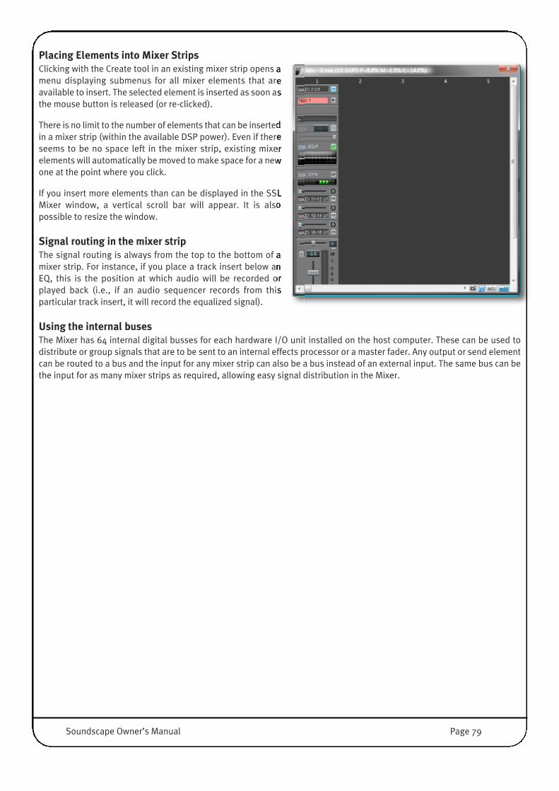
Placing Elements into Mixer StripsClicking with the Create tool in an existing mixer strip opens amenu displaying submenus for all mixer elements that areavailable to insert. The selected element is inserted as soon asthe mouse button is released (or re-clicked).
There is no limit to the number of elements that can be insertedin a mixer strip (within the available DSP power). Even if thereseems to be no space left in the mixer strip, existing mixerelements will automatically be moved to make space for a newone at the point where you click.
If you insert more elements than can be displayed in the SSLMixer window, a vertical scroll bar will appear. It is alsopossible to resize the window.
Signal routing in the mixer stripThe signal routing is always from the top to the bottom of amixer strip. For instance, if you place a track insert below anEQ, this is the position at which audio will be recorded orplayed back (i.e., if an audio sequencer records from thisparticular track insert, it will record the equalized signal).
Using the internal busesThe Mixer has 64 internal digital busses for each hardware I/O unit installed on the host computer. These can be used todistribute or group signals that are to be sent to an internal effects processor or a master fader. Any output or send elementcan be routed to a bus and the input for any mixer strip can also be a bus instead of an external input. The same bus can bethe input for as many mixer strips as required, allowing easy signal distribution in the Mixer.
Soundscape Owner’s Manual Page 79

Basic Mixer Strip StructureThis diagram shows signal routing through a stereo inputmixer strip.
The signal can be fed from an external input, sent internallyfrom another mixer strip via a ‘bus’, or received from aWindows application via a streaming input.
The Track Elements represent the ‘Tape’ Tracks, where theAudio can be routed to/from disk. The Track Elements canbe freely positioned inside the user definable area, hencePre or Post certain Plug-Ins. If a Track is located after aPlug-In, the processed Signal may be recorded to Disk.
Once the signal is in the strip, it can be mixed with a trackoutput, equalized, delayed, its level adjusted andmonitored, and then get sent to another mixer strip oroutput top be processed by ‘plug-ins’.
The fixed peak meters are pre-fader, so they show signaleven if the fader is down or if the mixer strip output ismuted. Any level changes resulting from an inserted faderor EQ will be shown by the fixed peak meters.
The numbering and naming of the availableinputs/outputs, buses and streams may vary dependingon the hardware configuration; i.e. The number and typeof SSL audio cards installed in the host computer, thecurrently selected sample rate, the selected MADI format(56Ch and 64Ch) and High Speed (64-96kHz) modes forAES, ADAT and TDIF.
Note that MadiXtreme routing is hard-wired – track 1uses MADI input 1 and output 1, and so on.
MX4:- MADI 1-128- STR 1-128- BUS 1-64
Mixpander:- AES/EBU, ADAT or TDIF 1-24- ANA 1-24- MADI 1-64 - STR 1-64- BUS 1-64
Input Assignment
Track Element
User-definable area
PPM (Pre-fader)
Pan/Balance
Fader
Output Assignment
MX4:- MADI 1-128- STR 1-128- BUS 1-64
Mixpander:- AES/EBU, ADAT or TDIF 1-24- ANA 1-24- MADI 1-64 - STR 1-64- BUS 1-64
DSP powered plug-ins,building blocks, VST plug-ins,Track Elements etc.
Page 80 Soundscape Owner’s Manual
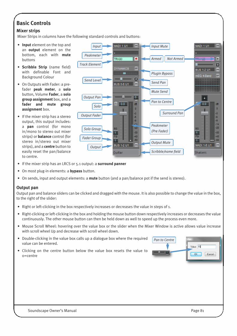
Basic ControlsMixer strips Mixer Strips in columns have the following standard controls and buttons:
• Input element on the top andan output element on thebottom, each with mutebuttons
• Scribble Strip (name field)with definable Font andBackground Colour
• On Outputs with Fader: a pre-fader peak meter, a solobutton, Volume Fader, a sologroup assignment box, and afader and mute groupassignment box.
• If the mixer strip has a stereooutput, this output includes:a pan control (for monoin/mono to stereo out mixerstrips) or balance control (forstereo in/stereo out mixerstrips), and a centre button toeasily reset the pan/balanceto centre.
• If the mixer strip has an LRCS or 5.1 output: a surround panner
• On most plug-in elements: a bypass button.
• On sends, input and output elements: a mute button (and a pan/balance pot if the send is stereo).
Output panOutput pan and balance sliders can be clicked and dragged with the mouse. It is also possible to change the value in the box,to the right of the slider:
• Right or left-clicking in the box respectively increases or decreases the value in steps of 1.
• Right-clicking or left-clicking in the box and holding the mouse button down respectively increases or decreases the valuecontinuously. The other mouse button can then be held down as well to speed up the process even more.
• Mouse Scroll Wheel: hovering over the value box or the slider when the Mixer Window is active allows value increasewith scroll wheel Up and decrease with scroll wheel down.
• Double-clicking in the value box calls up a dialogue box where the requiredvalue can be entered.
• Clicking on the centre button below the value box resets the value to0=centre
Pan to Centre
Input
Peakmeter
Track Element
Output Pan
Send Level
Solo
Output Fader
Scribble/name field
Solo Group
Fader Group
Output
Input Mute
Armed
Plugin Bypass
Mute Send
Send Pan
Pan to Centre
Not Armed
Surround Pan
Peakmeter
(Pre Fader)
Output Mute
Soundscape Owner’s Manual Page 81

Fader and mute groupsEach output element with a fader can be assigned to one of 99 fader groups, and to one of 99 solo groups. Group assignmentsare regardless of the output type, (mono, stereo, mono to stereo, 4, 6 or 8 channels, LRCS, or LRC-LsRs)
NOTE: A single mixer strip could can contain several output elements, each assigned to different fader and solo groups.
The fader group and solo group assignments can be selected in several ways:• Right-clicking or left-clicking in the relevant group assignment selection box respectively increases or decreases the value
in steps of 1.• Right-clicking or left-clicking in the selection box and holding the mouse button down respectively increases or decreases
the value continuously. The other mouse button can then be held down as well to speed up the process even more.• Mouse Scroll Wheel: hovering over the group box and increase with scroll wheel Up, decrease with scroll wheel down• Double-clicking in a selection box opens dialogue box where the required fader group number or solo group number can
be entered with the keyboard.
FadersWhenever several output faders are assigned to the same fader and mutegroup, clicking and dragging any single one of them with the right mousebutton will move all faders in the group .
The grouped faders keep their original position relative to each other whilethey are moving, until one or more of them reach minimum or maximum leveland cannot move any further.
Even then, moving back will restore its relative position within the group,provided the mouse button has not been released.
Mute buttonsThe mute buttons for grouped faders are also linked. Right-clicking on a mute button will cause all the mute buttons in thesame fader and mute group to switch to the same muted/unmuted status, regardless of their status before. The mute buttonscan be used individually, regardless of their fader group assignment, by clicking them with the left mouse button.
Solo groups• Left-clicking any inactive (grey) solo button solos the corresponding output and silences all other outputs that have the
same solo group assignment. • Any previously soloed output inside the same solo group is dropped out of solo mode and silenced, unless the [Ctrl] key
is used as described below. • The solo button turns bright red (Solo Listen), all other solo buttons in the same group switch to a red S on grey
background (Solo Muted).• Left-clicking again on the active (red) solo button deactivates Solo Mode for this entire group.
• Right-clicking an inactive solo button solos the corresponding output and all the outputs that have the same fader andmute group assignment.
• It also mutes all the outputs that have both a different fader and mute group assignment and the same solo groupassignment as any one of the soloed outputs.
• Any previously soloed output which has a different fader and mute group assignment and the same solo group assignmentis dropped out of solo mode and silenced, unless the [Ctrl] key is used as described below.
• The solo buttons of soloed outputs turn red, and the solo buttons of silenced outputs display a red S on a grey background.• Right-clicking on an already active solo button deactivates it, and also deactivates any other active solo button that has
the same fader and mute group assignment.
Solo buttons and the [Ctrl] keyIf the [Ctrl] key is held down while left-clicking or right-clicking an inactive solo button, everything works as describedpreviously except that any outputs that are already soloed remain soloed. The [Ctrl] key has no effect when left-clicking orright-clicking an already active solo button.
Page 82 Soundscape Owner’s Manual

Scribble StripsDouble-clicking on the Scribble Strips (Column Name Field) at the bottom of a mixer columnopens the Column Name dialogue box .
This function cannot be accessed while in Mix Edit mode.
You can define:• The Name of the Channel
• The Label Text Colour (Foreground Colour)
• The Label Colour (Background Colour)
• The choice of colours can be applied to the current column only, columns inside the samefader group or all Columns in the Mixer.
The Colours are defined by standard Windows Colour Dialogues which openwhen you click on the colour pads for foreground or background colour.
Using colour coding for text and labels really helps to maintain an overviewand allows quick identification of grouped columns, especially when youstart to build bigger Mixers and explore the endless possibilities of DSPbased grouping.
DSP Resources and DSP Auto RoutingIt is possible to ‘DSP mute’ mixer strips or mixer elements using the Mute tool (i.e. ‘turn the Hardware off’), and unlike whathappens in a hardware only digital mixer, in the SSL Mixer these muted mixer strips or elements do not consume DSP poweranymore. This means that you can construct a Mixer containing duplicated strips with different parameter settings, for easyA/B comparison. Or you could build a Mixer that has a higher processing power requirement than the DSP(s) can provide,and just activate the elements that you need at any given time.
This way, if you need to use more effects than available DSP power allows, you can adjust an effect in real-time, record theoutput to a track, and then mute the real-time effect to save processing power for other purposes.
NOTE: Pressing the BP button (bypass) for an element does not reduce the DSP power consumption, as the element isstill active (just bypassed) and instantly available. Only DSP muting the element with the Mute tool will reduce the DSPpower used.
Each mixer element consumes a certain percentage of DSP resources and the overall percentage for processing (P) andmemory (M) is shown in the Mixer window’s title bar. For example, for an MX4 a single mono mixer column with output faderis around (P)0.1% (M)0.3%, the 4 band mono multi EQ is (P)1.1% (M)0.3%, a mono peak meter is (P)0.1% (M)0.1%.
More complex elements use more DSP power, such as for example the stereo Chorus/Flanger from the Audio Toolbox plug-in which uses (P)2.1% (M)1.2%. If you DSP mute an element, you will see a reduction in DSP power usage, as long as thereis no ‘DSP masking’ taking place (another instance of the Plug-In is active and still needs to run some global plug-in code).
The DSP power percentage that is reported as being used for each element is the maximum percentage that this element willuse. In reality, there are several parameters that are important to the DSP, for example processing time, and program andmemory requirements. This means that when two elements are combined, the overall DSP power requirement may be lessthan the sum of both percentages (i.e., one element may need more memory and the other may take more processing time,but with less memory used). In this case one algorithm is ‘masking’ the power requirement for the other.
With multiple cards, the percentages are shown for each card individually.
Soundscape Owner’s Manual Page 83
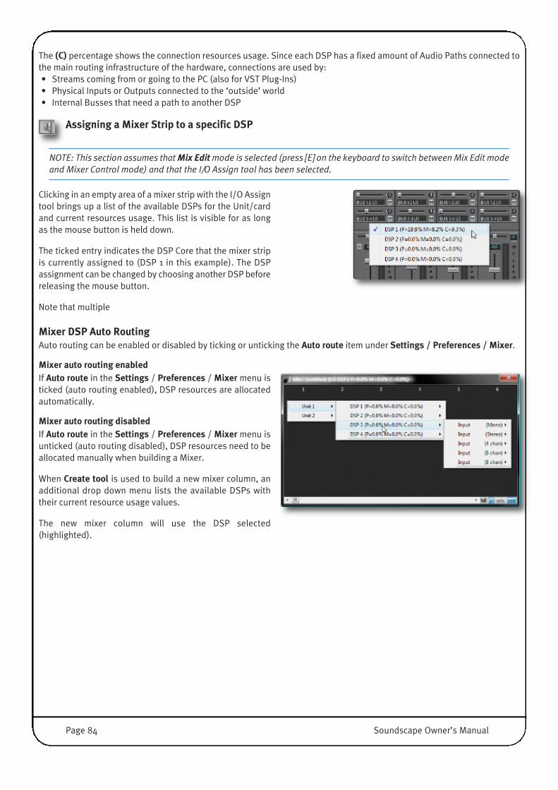
The (C) percentage shows the connection resources usage. Since each DSP has a fixed amount of Audio Paths connected tothe main routing infrastructure of the hardware, connections are used by:• Streams coming from or going to the PC (also for VST Plug-Ins)• Physical Inputs or Outputs connected to the ‘outside’ world• Internal Busses that need a path to another DSP
Assigning a Mixer Strip to a specific DSP
NOTE: This section assumes that Mix Editmode is selected (press [E] on the keyboard to switch between Mix Edit modeand Mixer Control mode) and that the I/O Assign tool has been selected.
Clicking in an empty area of a mixer strip with the I/O Assigntool brings up a list of the available DSPs for the Unit/cardand current resources usage. This list is visible for as longas the mouse button is held down.
The ticked entry indicates the DSP Core that the mixer stripis currently assigned to (DSP 1 in this example). The DSPassignment can be changed by choosing another DSP beforereleasing the mouse button.
Note that multiple
Mixer DSP Auto RoutingAuto routing can be enabled or disabled by ticking or unticking the Auto route item under Settings / Preferences / Mixer.
Mixer auto routing enabledIf Auto route in the Settings / Preferences / Mixer menu isticked (auto routing enabled), DSP resources are allocatedautomatically.
Mixer auto routing disabled�If Auto route in the Settings / Preferences / Mixer menu isunticked (auto routing disabled), DSP resources need to beallocated manually when building a Mixer.
When Create tool is used to build a new mixer column, anadditional drop down menu lists the available DSPs withtheir current resource usage values.
The new mixer column will use the DSP selected(highlighted).
Page 84 Soundscape Owner’s Manual

Mixer ViewsThe SSL Mixer has two display modes: Full View (wide) or Small View (narrow). Both options are available under the Viewmenu or by pressing the [X] or [Q] key on the computer keyboard. There is also an option to have the SSL Mixer windowAlways on top under the Settings / Mixer menu.
At 1024X768 display resolution, in Full View mode, up to 11 mixer columns can be displayed across the screen. In SmallView, up to 17 can be viewed, but in less detail.
In particular, the solo group assignment boxes and fader and mute group assignment boxes are hidden in Small View mode.Similarly, less parameters are displayed for certain mixer elements in Small View mode. However, in most cases, double-clicking the name field of a mixer element will open a new, dedicated window where all parameters can be viewed and edited,and presets, if applicable, can be loaded or saved.
Double-clicking a parameter field will open a dialogue box where the value for that particular parameter can be edited withtext input on the keyboard.
NOTE: Once a Mixer has been loaded, it remains active even if the window is closed.
The Mixer contains 128 mixer columns, each contains one mixer strip that is 1 to 8 Channels wide. A horizontal scroll bar isprovided for navigation across the Mixer window.
Mixer Strip
Full View
Mixer Strip
Small View
Mixer Element Window
Opened by double-clicking the mixer element’s name field
Mixer Element Parameter Dialogue Box
Opened by double-clicking the parameter field
Soundscape Owner’s Manual Page 85
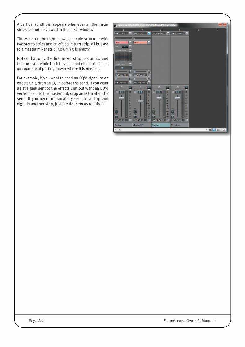
A vertical scroll bar appears whenever all the mixerstrips cannot be viewed in the mixer window.
The Mixer on the right shows a simple structure withtwo stereo strips and an effects return strip, all bussedto a master mixer strip. Column 5 is empty.
Notice that only the first mixer strip has an EQ andCompressor, while both have a send element. This isan example of putting power where it is needed.
For example, if you want to send an EQ’d signal to aneffects unit, drop an EQ in before the send. If you wanta flat signal sent to the effects unit but want an EQ’dversion sent to the master out, drop an EQ in after thesend. If you need one auxiliary send in a strip andeight in another strip, just create them as required!
Page 86 Soundscape Owner’s Manual

Input/Output IdentificationDepending on the SSL hardware that is used with the Mixer, the selection of available audio inputs and outputs will vary.
MX4Channel Inputs in the MX4 are named MADI 1-64 (1-56) for MADI Port A and MADI 65-128 (65-120) for MADI Port B, dependingon the MADI I/O mode 64Ch or (56Ch).
The MADI Mode is selected under Settings / I/O mode / MADI, and has to match the settings of the connected MADI Devices(Converters, Consoles, Routers).
Internal Buses are named Bus 1-64 , the Streaming Channels (PC Software I/O‘s) are named STR 1-128.
NOTE: When working at 96Khz, the number of MADI and Streaming I/O is reduced to 64.
MadiXtremeMadiXtreme routing is hard-wired – track 1 uses MADI input 1 and output 1, and so on. There are therefore no routing changeswhich can be made by the user.
MixpanderMixpander can handle 64 in/out from its expansion port, that can be connected to an SSL Alpha-Link or Soundscape iBoxinterface.
If connected to a legacy Soundscape 32 Unit, 26 inputs and 28 outputs can be used.
Mixpander also has 64 Buses (Bus 1-64) and 64 streaming channels (STR1-64).
On program start up, Soundscape detects which Unit is connected to the Mixpander and the I/O Labels will be namedaccordingly.
SSL XLogic Alpha-Link (or Soundscape iBox 24/48/64 Models)The SSL XLogic Alpha-Link and SSL Soundscape iBox 24/48/64 models offer a wide range of audio formats. Their inputs andoutputs are identified by a string of letters for the output type (ANA for Analogue I/O, AES for AES/EBU I/O, MADI for… MADII/O, ADAT for ADAT I/O, TDIF for.. TDIF, STR for Streaming I/O, BUS for Bus), one or two numbers (one for a mono input oroutput, two for a pair or larger group, e.g. 9-16 for an eight-channel input element), and a unit number if there is more thanone card present in the system.
NOTE: When working at 96Khz, the number of connections to the Alpha-Link Unit and Streaming I/O is reduced to 32.
Soundscape 32 workstation connected to a MixpanderThe Soundscape 32 audio workstation offers 3 TDIF ports that provide a total of 24 i/o and are identified in the SSL Mixer asTDIF1 to 8, TDIF9 to TDIF16 and TDIF17 to TDIF24 inputs and outputs.
The AES/EBU stereo input connector is named DIGITAL AES/EBU IN1/2.
The two AES/EBU stereo output connectors named DIGITAL AES/EBU OUT1/2 and OUT3/4.
The two balanced XLR inputs are identified as the ANA1 and ANA2.
The four balanced XLR outputs are named ANA1, ANA2, ANA3 and ANA4.
NOTE: When working at 96Khz, the number of I/O‘s is limited to 16 and Streaming I/O is reduced to 32.
Soundscape Owner’s Manual Page 87

Mixer Inactive BuildFor each change that is made in Edit Mode, the DSP code needs to be updated – all of the DSP code may have to berestructured and spread differently across all DSP‘s. While this is happening, no further editing is possible. Depending on theamount of DSP Code that needs reloading (in other words, depending on the size of your mixer), this could take anything upto a second.
In order to speed up the building process, you can also use ‘Inactive Build’. Here, the Mixer gets deactivated (no DSP Codeloaded) and you can edit your structure, add Strips and elements instantly. Once you are done, just activate this Mixer andall of the DSP Code is loaded in one go.
If native mixer elements such as VST plug-ins are used, native processing is also stopped while the Mixer is being edited.
To use Mixer Inactive Build, hold the [Shift] key downwhile performing the required edits. The title bar willdisplay Inactive after the P, M and C values, and thechanges you make will be reflected instantly on screen.
The [Shift] key can be released before the last edit iscarried out in order to reactivate the edited Mixer.
Alternatively, you can double click on the Caption barto reactivate the Mixer.
DSP power limitThe P value reported in the Mixer window’s title bar is the percentage of theavailable DSP clock cycles required to run the Mixer at the selected Sample Rate(taking the Varispeed setting into account). The M value is the percentage ofmemory resources required to run the Mixer. In most cases, if either of thesevalues exceeds 100% when a Mixer is created, the following warning message isdisplayed.
After you click OK, the title bar will display the ‘P’ and‘M’ values so that you can see which one exceeds theavailable resources, and by how much.
If only the P value exceeds 100%, the title bar willdisplay a DSP Power Warning.
If the M value or both values exceed 100%, the title barwill inform you that the Mixer is inactive.
Muting or deleting some elements will reduce the values and reactivate the Mixer.
However, the P=xx% value is not always completely accurate, because some plug-in elements may report inaccurateprocessing cycles. This means that depending on the elements used, some Mixers can't reach or may exceed the P=100%value without any warning box appearing.
Also the Mixer DSP measures the actual processing cycles used for every sample, and warns if a real mixer processing cycleoverrun occurs. If this is the case, a warning is given in the caption bar of the mixer window, and the mixer is muted for abouthalf a second. The warning can also be reset by double-clicking the caption bar of the mixer window.
Page 88 Soundscape Owner’s Manual
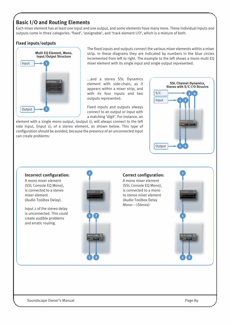
Basic I/O and Routing ElementsEach mixer element has at least one input and one output, and some elements have many more. These individual inputs andoutputs come in three categories: ‘fixed’, ‘assignable’, and ‘track element I/O’, which is a mixture of both.
Fixed inputs/outputsThe fixed inputs and outputs connect the various mixer elements within a mixerstrip. In these diagrams they are indicated by numbers in the blue circlesincremented from left to right. The example to the left shows a mono multi EQmixer element with its single input and single output represented.
...and a stereo SSL Dynamicselement with side-chain, as itappears within a mixer strip, andwith its four inputs and twooutputs represented.
Fixed inputs and outputs alwaysconnect to an output or input witha matching ‘digit’. For instance, an
element with a single mono output, (output 1), will always connect to the leftside input, (input 1), of a stereo element, as shown below. This type ofconfiguration should be avoided, because the presence of an unconnected inputcan create problems:
Incorrect configuration:A mono mixer element (SSL Console EQ Mono), is connected to a stereo mixer element (Audio Toolbox Delay).
Input 2 of the stereo delay is unconnected. This could create audible problems and erratic routing.
Correct configuration:A mono mixer element (SSL Console EQ Mono),is connected to a mono to stereo mixer element(Audio Toolbox Delay Mono->Stereo)
?
2
1
1
1
1
1
1 2
1
1
2
2
Input
Output
SSL Channel Dynamics,Stereo with S/C I/O Structre
3 4S/C
Input 1
Output 1
Multi EQ Element, Mono,Input/Output Structure
Soundscape Owner’s Manual Page 89

It is important to take this into account when building a Mixer, since the two configurations shown above would look the samewithin a mixer strip. If you need to check the input/output configuration of an existing mixer element, click on it with the Infotool in Mix Edit mode. A window containing the relevant information will be displayed.
NOTE: The principles outlined in the examples above using mono, stereo and mono to stereo mixer elements also applywhen dealing with mixer elements that have a higher number of inputs and outputs. For example, combining a 6 in/6out input element and an 8 in/8 out output element within a mixer strip would result in an incorrect configuration,because inputs 7 and 8 of the output element would be left unconnected.
Assignable inputs/outputsThe assignable inputs andoutputs connect mixer elementsacross mixer strips, to theexternal inputs and outputs ofthe MX4 or Mixpander, or to thehost PC via the ‘streams’. In ourdiagrams they are not numbered.Instead they are indicated by an‘A’, meaning that their routingcan be determined freely usingthe I/O Assign tool. Theindividual input(s) of inputelements and individualoutput(s) of output or sendelement(s) are assignable in thisway.
The example above shows an 8 in/8 out output element. Initially, the element’s outputs are assigned to outputs 1-8. The I/OAssign tool is then used to change the element’s output assignment to outputs 9-16.
As well as transmitting the audio data they receive via their assignableoutput(s), incl. any volume and pan/balance settings and the mutestatus, send elements and output elements also let the original datapass through to any element placed below them, (i.e., unaffected bythese settings and regardless of mute status).
These signals will feed any assignable input(s) in the Mixer that is (are)set to BUS 5-6.
In the example to the right, the data received at inputs 1 and 2 will beoutput :
• via buses 5 and 6 (assignable outs shown as ‘A’)
• original signal will reach the multi EQ element placed below thesend
A
1
1
1
2
2
2
A
These signals
will feed any
assignable
input(s) in the
Mixer which are
set to Bus 5-6
1
A
Output Element, assigned to MADI Outputs 1-8
2
A
3
A
4
A
5
A
6
A
7
A
8
A
1
A
Output Element, now assigned to MADI Outputs 9-16
2
A
3
A
4
A
5
A
6
A
7
A
8
A
Page 90 Soundscape Owner’s Manual

Assigning I/O on Multiple Mixer StripsAny Mixer Element that contains an I/O assignment area (Inputs/Outputs/Sends), can be changed on multiple selectedcolumns simultaneously. Using the I/O Assign tool on any element within the current column selection will change theidentical* elements on all selected columns to the chosen I/O value.
Pressing and holding the [CTRL] key while clicking on a certain element inside the column selection will change this elementto the chosen I/O, and then decrement this value on selected columns to the left and increment it on selected columns to theright.
*IDENTICAL ELEMENTS: • The Mixer only considers elements to be identical across columns if they are using the same element type and theirvisual vertical position inside the Mixer strip is vertically overlapping or the same. • If two of the same element type are visually overlapping (i.e. 2 Send Elements), the top element will be changed. • Mixer strips, I/O's and Sends with a different channel count or routing layout (i.e.. Mono to Mono, Mono to Stereo,Stereo Send, Stereo EPP Send) are not considered to be identical, regardless of their vertical visual position.
Track ElementsThe Track Elements are a mixture of fixed and assignable I/O's. TrackElements always connect to Audio Tracks in the Arrange window (fixed),however the Track they are connected to is assignable.
In Record mode (Track is armed) the Input of the Track is always routedto the disk and from there back to the Track Output (independent of theselected Mix Input Always status described below).
When an Auto Punch In or Punch In/Out is set in the Arrange Windowduring recording, the Track Element at Punch-In will switch from DiskPlayback present at the Track Output to the Track Output being directlyfed from the Track Input (if Mix Input Always is not checked).
This makes it possible to use a Bus/Tape Style Artist Monitoring andpreview an overdub while recording it.
Mix Input AlwaysIn Play mode (Track not armed) the Input of the Track (1) is available tobe mixed with the audio coming from disk. To do this, double-click onTrack Element and check Mix Input Always) at the Track’s Output.
The surround of the send’s track arming icon will go blue to indicate thatMix Input Always is active.
NOTE: Track Elements as well as ‘native’ VST Plug-Ins are using streams from the SSL Card to exchange audio betweenthe DSP's and the PC's Host CPU. While you can select a certain Stream number for I/O and Send Elements, TrackElements and VST Plug-Ins will dynamically be assigned to unused streams (as long as there are any left) automatically.If no streams are left a ‘stream exhausted’ error message will appear.
�
1
1
1
Mixinputalways
Soundscape Owner’s Manual Page 91

Mixer Strip Input/Output ConfigurationsWhen you select the Create tool and click in an empty mixer slot in Mix Edit mode, a menu appears, prompting you to createa new mixer column. If you have several units in your system, the menu will let you choose the unit (i.e., the DSP and actualinputs/outputs) that the mixer column will be created for.
Several mixer column configurations are available which all include ‘built-in’ input and output elements.
The output element always has a mute button, and may have a fader, pan or balance control, peak meter, and solo button.
An EPP (Equal Power Panning) output can be selected for stereo and mono to stereo outputs.
Mixer column input/output configurations using mono and stereo:• For mono in - mono out, the signal just flows through the mixer column, only affected by
the user defined settings of the various mixer elements, which also should be mono.• For stereo in - stereo out, the respective level of the left and right signals is controlled
by the balance setting (available if there is a fader). Stereo mixer elements would beinserted in the signal path as required.
• For mono in - mono to stereo out, the signal path through the mixer column is mono,and the signal is split into stereo before the pan control.
For mono in - stereo out, the input is mono, but the input signal needs to reach both inputsof a stereo output element. This mixer column configuration should only be created in orderto use a stereo process or effect on a mono source (e.g., a mono to stereo chorus or reverb).
In fact, if you use this configuration without inserting a mono to stereo process in the mixercolumn, then the input element will not be connected to Input 2 of the output element, andthis should be avoided as it can have undesirable effects (the right hand side channel of theoutput element may pick a signal from elsewhere in the Mixer).
In the example on the right, a mono signal reaches the mixer column via the MADI 1 input.
A mono to stereo Chorus effect is applied.
The chorus's stereo pair of outputs connects as required to the stereo output element.
A
1
1
A
mono in – stereo out mixer strip
connection diagram
2
A
Page 92 Soundscape Owner’s Manual

For stereo in - mono out, only the left side of the stereo input will be connected to the mixercolumn’s output.
This configuration can be used to insert a 2 in/1 out mixer element such as a monocompressor with side-chain input.
The main signal will reach the compressor via MADI input 1, the key signal will reach thecompressor via MADI input 2.
Only the main signal will reach the compressor’s single output.
For stereo in - mono to stereo out, only the left side of thestereo input is connected through the mixer column, but itsplits into stereo at the pan control.
This configuration, just like the stereo in - mono outconfiguration described above, can be used to insert a 2in/1 out mixer element such as a mono compressor withside-chain input.
The only difference is that the output can be panned left orright as required with the mono to stereo output element.
A
1
A
Stereo in –mono-to-stereo out
mixer strip connection diagram
A
2
1
A
A
1
A
Stereo in – mono out mixer strip
connection diagram
A
2
1
Soundscape Owner’s Manual Page 93

Stereo Balance and PanningStereo and mono to stereo outputs can be selected with Equal Power Panning (EPP menu options).
In this case, when the balance or pan control is moved to one side, the level for that side is gradually increased by up to 3dBto compensate for the overall loss of power from the other side.
4 in - stereo outThis configuration would be used to insert a 4 in/2 out mixer element such as a stereocompressor with side-chain input.
The main signal must reach the compressor via MADI inputs 1-2,
the key signal (or Sidechain) must reach the compressor via MADI inputs 3-4.
Only the main signal will reach the compressor’s outputs.
A
1
A
4 in – stereo out mixer strip
connection diagram
A
2
1
A
2
A
3
A
4
Page 94 Soundscape Owner’s Manual

Surround Mixing I/O ConfigurationsFor mono in - mono to LRCS out, the signal path through the mixer column is mono, allowingmono processes or effects to be applied to the signal.
The mono multi EQ in the example, is applied before the eq‘d signal is positioned in thesound field using the surround panner.
A stereo in - stereo to LRCS out configuration is similar to the mono in- mono to LRCS outconfiguration, except that the signal path through the mixer column is stereo, allowingstereo processes or effects to be applied to the signal.
Routing in this example: In this example the output routing of the LRCS signal is:
• MADI 1: L
• MADI 2: R
• MADI 3: C
• MADI 4: S
mono to LRCS panner stereo to LRCS panner
A
1
A
mono in – mono-to-LCRS mixer strip
connection diagram
1
A A A
Soundscape Owner’s Manual Page 95

The mono in - mono to 5.1 out configuration is similar to the mono in - mono to LRCS outconfiguration, except that the output element has six individual outputs for 5.1:• L • R• C• LFE• Ls• Rs
The stereo in - stereo to 5.1 out configuration is similar to the mono in- mono to 5.1 outconfiguration, except that the signal path through the mixer column is stereo, allowingstereo processes or effects to be applied to the signal.
Routing in this example: • MADI 1: L • MADI 2: R• MADI 3: C• MADI 4: LFE• MADI 5: L S• MADI 6: R S
mono to 5.1 panner stereo to 5.1 panner
A
1
A
mono in – mono-to-5.1 mixer strip
connection diagram
1
A A
A A A
Page 96 Soundscape Owner’s Manual

For mixer columns with a mono or stereo to LRCS or 5.1output, double-clicking the output element just next to thesmall surround panner, or in the output assignment box willopen the Surround Panner window.
The panner features individual pan dots for the Left (white ormono) and Right (red, stereo panner only) input signal(s).
These dots can be moved across the sound field using theleft and right mouse buttons respectively, by clicking anddragging or by clicking at the required position in the soundfield.
The pan dots can be moved either in the small panner in themixer column or in the large panner window.
In the large window, it is also possible to use the X and Ysliders, or the X and Y value boxes. For surround pannerswith a stereo input, L and R buttons, positioned above the Xfader, indicate whether the Left or Right signal panning iscurrently controlled by the X and Y faders.
The Front, Rear and F/R (Front/Rear) divergence controlsallow the sound to blend gradually, respectively betweenthe front speakers (as if the front speakers were broughtcloser to each other), rear speakers (as if the rear speakers were brought closer to each other) or front and rear speakers (asif all the speakers were brought closer to each other). Higher values create more separation.
The Centre Speaker control allows centre panned sound to be gradually spread across the left and right front speakers.
The LFE (dB) level control (for 5.1 output panners only) determines the level of the signal routed to the LFE channel (preoutput fader). Clicking the ‘Speaker’ icon above the LFE fader will mute/unmute the LFE output channel (the LFE fader appearsdimmed when the LFE channel is muted).
NOTE: The panning mode is always ‘equal power’, regardless of panning position, divergence or centre speaker controlsettings. Muted speakers are not taken into account though!
�
Soundscape Owner’s Manual Page 97

X, Y, Divergence, Centre and LFE controls:• The sliders can be moved either by clicking and dragging them or by clicking at the required position with the mouse
• Right-clicking or left-clicking in a value box respectively increases or decreases the corresponding value in steps of 1.Right-clicking or left-clicking in the selection box and holding the mouse button down increases or decreases the valuecontinuously. The other mouse button can then be held down as well to speed up the process even more
Speaker Icons:• Clicking a speaker icon mutes/unmutes the corresponding speaker output
• Right-clicking a speaker icon solos/unsolos the corresponding speaker output
• The output level for each speaker is displayed in dB
For stereo to LRCS and stereo to 5.1 output panners only:• Left (L) and Right (R) buttons (positioned above the X pan fader) can be used to link the X and Y pan faders to either pan
dot
• Four ‘L<−>R Pan Relation mode’ buttons allow the pan dot positions to be controlled independently, or allow the dots tobe linked so that their positions are automatically mirrored horizontally, vertically or diagonally when moving either pandot.
The output routing of the mono to LRCS and stereo to LRCS output panners is Left, Right, Centre, Surround, so that the leftand right signals are on adjacent buses or outputs, in case just the stereo signal is required.
The outputs would be routed to four full bandwidth speakers, three across the front (L, C and R), and a rear surround speaker(S).
Similarly, the output routing of the mono to 5.1 and stereo to 5.1 output panners is Left, Right, Centre, LFE, Left surround, Rightsurround. For instance, if the output element is assigned to MADI1-6 U1, the output routing would be: • L → MADI1 U1
• R → MADI2 U1
• C → MADI3 U1
• LFE → MADI 4 U1
• Ls → MADI5 U1
• Rs → MADI6 U1
Independent L/R pan positions
Diagonally mirrored L/R pan positions
Vertically mirrored L/R pan positions
Horizontally mirrored L/R pan positions
Page 98 Soundscape Owner’s Manual
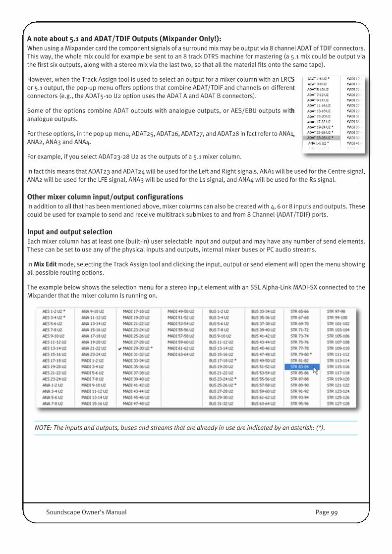
A note about 5.1 and ADAT/TDIF Outputs (Mixpander Only!):When using a Mixpander card the component signals of a surround mix may be output via 8 channel ADAT of TDIF connectors.This way, the whole mix could for example be sent to an 8 track DTRS machine for mastering (a 5.1 mix could be output viathe first six outputs, along with a stereo mix via the last two, so that all the material fits onto the same tape). �
However, when the Track Assign tool is used to select an output for a mixer column with an LRCSor 5.1 output, the pop-up menu offers options that combine ADAT/TDIF and channels on differentconnectors (e.g., the ADAT5-10 U2 option uses the ADAT A and ADAT B connectors).
Some of the options combine ADAT outputs with analogue outputs, or AES/EBU outputs withanalogue outputs.
For these options, in the pop up menu, ADAT25, ADAT26, ADAT27, and ADAT28 in fact refer to ANA1,ANA2, ANA3 and ANA4.
For example, if you select ADAT23-28 U2 as the outputs of a 5.1 mixer column.
In fact this means that ADAT23 and ADAT24 will be used for the Left and Right signals, ANA1 will be used for the Centre signal,ANA2 will be used for the LFE signal, ANA3 will be used for the Ls signal, and ANA4 will be used for the Rs signal.
Other mixer column input/output configurationsIn addition to all that has been mentioned above, mixer columns can also be created with 4, 6 or 8 inputs and outputs. Thesecould be used for example to send and receive multitrack submixes to and from 8 Channel (ADAT/TDIF) ports.
Input and output selectionEach mixer column has at least one (built-in) user selectable input and output and may have any number of send elements.These can be set to use any of the physical inputs and outputs, internal mixer buses or PC audio streams.
In Mix Edit mode, selecting the Track Assign tool and clicking the input, output or send element will open the menu showingall possible routing options.
The example below shows the selection menu for a stereo input element with an SSL Alpha-Link MADI-SX connected to theMixpander that the mixer column is running on.
NOTE: The inputs and outputs, buses and streams that are already in use are indicated by an asterisk: (*).
�
Soundscape Owner’s Manual Page 99

There are no restrictions to how you can use the inputs, outputs, buses or streams, and every signal routed to an output orbus is mixed in equal proportion (after the output or send fader). For instance, you could have 8 channels with MADI 1-2 U1(or Bus 1-2) as the input, and Bus 3-4 as the output routing. You could then use different EQ settings to split the signal,process it with different effects (e.g., for a multiband compressor) and recombine the signals at Bus 3-4. You could evenselect the same bus as the input and output of a mixer column, but be careful as you can have digital feedback this way!
This example shows the menu for a stereo send, in amixer column running on a MX4:
The streaming channels are automatically available to allaudio programs. For example, they can be used as inputsand outputs in a MIDI + Audio sequencer..
NOTE: If the output(s) from several mixer columns are sent directly to an external output (or group of outputs), it is notpossible to view the combined output signal in order to check for overload. Therefore, it is advisable instead to routethe mixer column outputs to a bus, and then to create an additional mixer column which has that bus as its input. Thismixer column should have a fader with peak meter, for monitoring the combined signal, and its output(s) can be routedto the required external output(s). This also provides a master fader for the combined signal.
�
Page 100 Soundscape Owner’s Manual
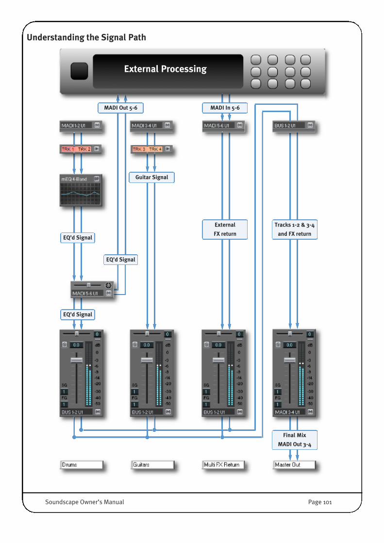
Understanding the Signal Path
External Processing
MADI Out 5-6 MADI In 5-6
Guitar Signal
EQ’d Signal
External
FX returnEQ’d Signal
EQ’d Signal
Tracks 1-2 & 3-4
and FX return
Final Mix
MADI Out 3-4
Soundscape Owner’s Manual Page 101
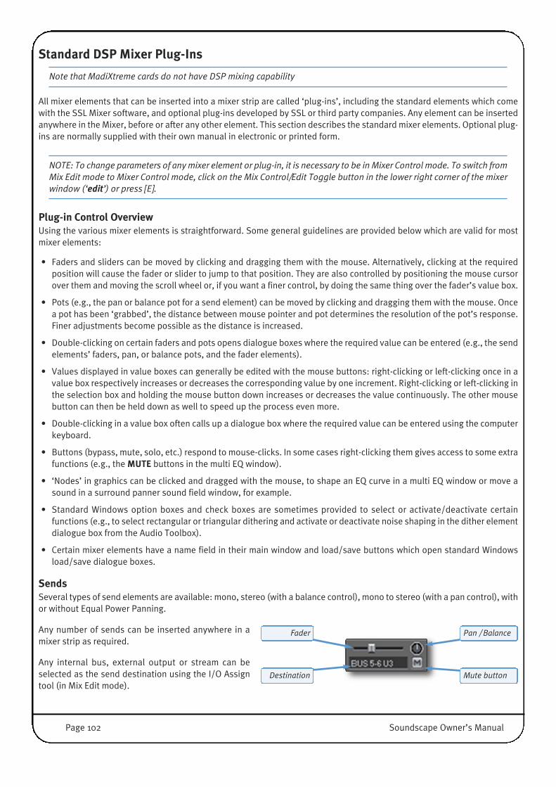
Standard DSP Mixer Plug-Ins
Note that MadiXtreme cards do not have DSP mixing capability
All mixer elements that can be inserted into a mixer strip are called ‘plug-ins’, including the standard elements which comewith the SSL Mixer software, and optional plug-ins developed by SSL or third party companies. Any element can be insertedanywhere in the Mixer, before or after any other element. This section describes the standard mixer elements. Optional plug-ins are normally supplied with their own manual in electronic or printed form.
NOTE: To change parameters of any mixer element or plug-in, it is necessary to be in Mixer Control mode. To switch fromMix Edit mode to Mixer Control mode, click on the Mix Control/Edit Toggle button in the lower right corner of the mixerwindow (‘edit’) or press [E].
Plug-in Control OverviewUsing the various mixer elements is straightforward. Some general guidelines are provided below which are valid for mostmixer elements:
• Faders and sliders can be moved by clicking and dragging them with the mouse. Alternatively, clicking at the requiredposition will cause the fader or slider to jump to that position. They are also controlled by positioning the mouse cursorover them and moving the scroll wheel or, if you want a finer control, by doing the same thing over the fader’s value box.
• Pots (e.g., the pan or balance pot for a send element) can be moved by clicking and dragging them with the mouse. Oncea pot has been ‘grabbed’, the distance between mouse pointer and pot determines the resolution of the pot’s response.Finer adjustments become possible as the distance is increased.
• Double-clicking on certain faders and pots opens dialogue boxes where the required value can be entered (e.g., the sendelements’ faders, pan, or balance pots, and the fader elements).
• Values displayed in value boxes can generally be edited with the mouse buttons: right-clicking or left-clicking once in avalue box respectively increases or decreases the corresponding value by one increment. Right-clicking or left-clicking inthe selection box and holding the mouse button down increases or decreases the value continuously. The other mousebutton can then be held down as well to speed up the process even more.
• Double-clicking in a value box often calls up a dialogue box where the required value can be entered using the computerkeyboard.
• Buttons (bypass, mute, solo, etc.) respond to mouse-clicks. In some cases right-clicking them gives access to some extrafunctions (e.g., the MUTE buttons in the multi EQ window).
• ‘Nodes’ in graphics can be clicked and dragged with the mouse, to shape an EQ curve in a multi EQ window or move asound in a surround panner sound field window, for example.
• Standard Windows option boxes and check boxes are sometimes provided to select or activate/deactivate certainfunctions (e.g., to select rectangular or triangular dithering and activate or deactivate noise shaping in the dither elementdialogue box from the Audio Toolbox).
• Certain mixer elements have a name field in their main window and load/save buttons which open standard Windowsload/save dialogue boxes.
SendsSeveral types of send elements are available: mono, stereo (with a balance control), mono to stereo (with a pan control), withor without Equal Power Panning.
Any number of sends can be inserted anywhere in amixer strip as required.
Any internal bus, external output or stream can beselected as the send destination using the I/O Assigntool (in Mix Edit mode).
Fader Pan / Balance
Destination Mute button
Page 102 Soundscape Owner’s Manual

All send elements have a mute button.
Double-clicking on a send element opens the following dialogue box:• Pre-fader sends (box unchecked) do not respond to changes made to output
element settings, regardless of the output element’s position in the mixer strip.• Post-fader sends (box checked) respond to changes made to the fader, mute
button and solo button settings of all outputs placed below them, except wherethese outputs are separated from the send element by an input element.
Please note the light blue identifying marks present on post-fade sends whichallow you to see the pre/post status of a send at a glance.
If you want to use a send element as an auxiliary send to an external effects unit,set the routing of that send element (using the Track Assign tool in Mix Edit mode) to the required external output(s). The wetsignal can be returned via an input element within the same mixer strip (placed after the send to prevent feedback loops!),or to another mixer strip altogether.
If you want to use a send element as an auxiliary send to an internal plug-in effect, you can route the send to a bus, create anew mixer strip which has that bus as its input, and insert the required plug-in effect in the new mixer strip.
NOTE: As well as sending a duplicate of the signal to the selected send destination, a send element still passes theoriginal signal down to the next element below inside the mixer strip.
EQ 2-bandThe 2-band EQs are fully parametric, allowing band-pass or notch filters withvariable Q (bandwidth), level and centre frequency. You can place multiple EQs ina mixer strip to add more bands.
The Quality Factor (Q) determines how selective (narrow) the filter is. High Q meansa narrow filter. The Q factor value is calculated by dividing the centre frequencywith the bandwidth of the filter. If you are more used to working with ‘octaves’instead of Q, ‘2 octaves’ means that the bandwidth is twice the centre frequencyand hence it has a Q of 0.5.
EQ parameters can be adjusted in real-time using the mouse buttons in the EQ parameters value boxes in the mixer strip, orusing the scroll wheel. If you hold down both mouse buttons, the EQ parameters can be changed more quickly, and thedirection of the change is determined by the mouse button pressed first. Double-clicking on a parameter opens a dialoguebox where the value can be entered with the keyboard.
The mono 2-band EQ element has two separate fully parametric sections; For the stereo 2-band EQ, there are four linkedactive EQs, providing two bands for each channel.
Double click (with Mix Edit inactive) on the little Mixer Window toopen the EQ-2 Band GUI.
The response of the EQ is shown in the curve display and you canadjust the parameters using the faders or value boxes in the usualway.
Multiple EQ windows can be opened at the same time, the captionbar shows to which element in which column the GUI belongs to.
Below the caption bar the usual SSL Mixer GUI Top bar allowsLoading and Saving of Presets and a Bypass button.
Pre Fader Post Fader
Soundscape Owner’s Manual Page 103

Multi EQThe multi EQ is a very flexible and DSP efficient Equaliser. Several variants of the multi EQ areavailable: 1-band, 2-band, 3-band, or 4-band, with each available in mono or stereo. As usual, moremulti EQs can be inserted into each mixer strip if you need more bands.
The little Mixer Window shows the EQ-Curve right inside the Mixer strip. You cannot edit the EQ fromhere. Double-click the multi EQ element to open the main GUI, shown below.
If the signal overloads, the EQ curve will change from blue to red(also in the little Mixer Graph); If this happens, use the Inputattenuation in the lower-left of the window to decrease the Inputvolume. (Click and drag the fader, click at the desired fader position,or use the value box.)
On the right of the input attenuator, there are tabs for each EQ band.Four parameter fields (Type, Frequency, Q-factor, and Gain) allowflexible manipulation of the currently selected band. Each band alsohas an individual mute button (M).
The F-Type parameter offers eight different options: low pass, highpass, band pass with constant skirt gain, band pass with constantpeak gain, peaking EQ, notch filter, low shelving, and high shelving.Types are indicated by the icons on the buttons and by hover-overlabels.
Frequency, Q-factor, and Gain, can be edited using the rotary knobsor the value boxes:
Knobs can be ‘clicked and dragged’ with the mouse. Once a knobhas been ‘grabbed’, the distance between mouse pointer and knobdetermines the resolution of the knob’s response. Finer adjustmentsare possible when the distance is increased. Alternatively, clickingat the desired position in the area around the knob sets the valueimmediately.
The values for the EQ bands’ parameters can be edited by clicking (or clicking and holding) the small up and down buttonsinside the value boxes. Alternatively, to enter a parameter value with the keyboard, simply double-click on a value box.
Left-clicking the mute (M) button toggles between mute and unmute of the EQ band. The button is highlighted when the EQband is muted.
Right-clicking a mute (M) button ‘solos’ the corresponding EQ band, meaning that the other EQ bands become inactive/muted.When an EQ band is ‘soloed’, right-clicking M a second time returns all the buttons to their previous state, and left-clickingleaves all bands muted.
Right-clicking in the tab label will open a menu with options to restore default settings for that EQ band or for all EQ bands,to activate or deactivate solo mode for that EQ band.
Page 104 Soundscape Owner’s Manual
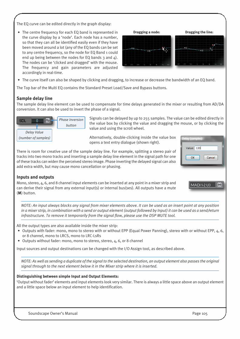
The EQ curve can be edited directly in the graph display:
• The centre frequency for each EQ band is represented inthe curve display by a ‘node’. Each node has a number,so that they can all be identified easily even if they havebeen moved around a lot (any of the EQ bands can be setto any centre frequency, so the node for EQ Band 1 couldend up being between the nodes for EQ bands 3 and 4).The nodes can be ‘clicked and dragged’ with the mouse.The frequency and gain parameters are adjustedaccordingly in real-time.
• The curve itself can also be shaped by clicking and dragging, to increase or decrease the bandwidth of an EQ band.
The Top bar of the Multi EQ contains the Standard Preset Load/Save and Bypass buttons.
Sample delay lineThe sample delay line element can be used to compensate for time delays generated in the mixer or resulting from AD/DAconversion. It can also be used to invert the phase of a signal.
Signals can be delayed by up to 255 samples. The value can be edited directly inthe value box by clicking the value and dragging the mouse, or by clicking thevalue and using the scroll wheel.
Alternatively, double-clicking inside the value boxopens a text entry dialogue (shown right).
There is room for creative use of the sample delay line. For example, splitting a stereo pair oftracks into two mono tracks and inserting a sample delay line element in the signal path for oneof these tracks can widen the perceived stereo image. Phase inverting the delayed signal can alsoadd extra width, but may cause mono cancellation or phasing.
Inputs and outputsMono, stereo, 4, 6, and 8 channel input elements can be inserted at any point in a mixer strip andcan derive their signal from any external input(s) or internal bus(ses). All outputs have a mute(M) button.
NOTE: An input always blocks any signal from mixer elements above. It can be used as an insert point at any positionin a mixer strip, in combination with a send or output element (output followed by Input) it can be used as a send/returninfrastructure. To remove it temporarily from the signal flow, please use the DSP MUTE tool.
All the output types are also available inside the mixer strip:• Outputs with fader: mono, mono to stereo with or without EPP (Equal Power Panning), stereo with or without EPP, 4, 6,
or 8 channel, mono to LRCS, mono to LRC-LsRs• Outputs without fader: mono, mono to stereo, stereo, 4, 6, or 8 channel
Input sources and output destinations can be changed with the I/O Assign tool, as described above.
NOTE: As well as sending a duplicate of the signal to the selected destination, an output element also passes the originalsignal through to the next element below it in the Mixer strip where it is inserted.
Distinguishing between simple Input and Output Elements: ‘Output without fader’ elements and input elements look very similar. There is always a little space above an output elementand a little space below an input element to help identification.
Delay Value
(number of samples)
Phase Inversion
button
Dragging a node: Dragging the line:
Soundscape Owner’s Manual Page 105

FadersMono and stereo faders can be inserted at any point inside a mixer strip. You can adjust the Gain between -96dB and + 6dB.
Peak MetersMono and stereo peak meters can be inserted at any pointinside a mixer strip.
MS DecoderThe gain and width parameters for an MS signal can beadjusted directly in the mixer strip using the mouse buttonsor scroll wheel. If you hold down both mouse buttons thevalues can be changed more quickly, and the direction of thechange is determined by the mouse button pressed first.
Double-clicking a parameter value allows text entry with thekeyboard.
Double-clicking on the mixer element opens the main MSDecoder window:
Input SectionIf the Lock Mid button is active, the relative gain of the midMS matrix input signal is not affected by the ‘width’ setting.
If the button is inactivated, the relative gains of the mid andside MS matrix input signals vary at the same time and inopposite directions.
The Gain slider controls the overall input gain applied to both input channels. (-36.0 to 6.0dB)
The Width slider controls the ratio of the side MS matrix input signal gain to the gain of the mid MS matrix inputsignal. (0.00 to 3.00)
Matrix/Routing Section• The Swap Inputs button swaps the input channels before the signals enters the MS matrix .
• The Swap Outputs button swaps the output channels post MS matrix .
• The Mid On/Off button cuts the mid MS matrix input signal, so that the effectof the MS matrix on the side signal can be monitored easily.
• Clicking the Side On/Off button cuts the side MS matrix input signal, so thatthe effect of the MS matrix on the mid signal can be monitored easily.
• The MS Matrix On/Off button toggles MS decoding Matrix between on(illuminated) and off status.If MS decoding is turned off, the signals are still affected by the gain, widthand bass shelving settings. However, the asymmetry and rotation parameterswill have no effect on the output signals.
NOTE: If the MS matrix is active, both input signals are attenuated by 6 dB. Then they are subtracted and summed toextract the left and right output signals.
Swap
Inputs
Swap
Outputs
Mid
On/Off
Side
On/Off
MS Matrix
On/Off
Lock Mid Active Lock Mid Inactive
Mono peak meter Stereo peak meter
Page 106 Soundscape Owner’s Manual
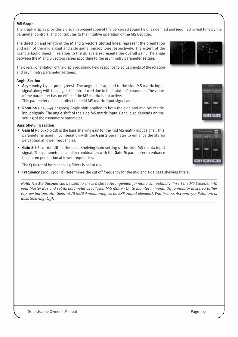
MS GraphThe graph display provides a visual representation of the perceived sound field, as defined and modified in real time by theparameter controls, and contributes to the intuitive operation of the MS Decoder.
The direction and length of the M and S vectors (dotted lines) represent the orientationand gain of the mid signal and side signal microphone respectively. The extent of thetriangle (solid lines) in relation to the dB scale represents the overall gain; The anglebetween the M and S vectors varies according to the asymmetry parameter setting.
The overall orientation of the displayed sound field responds to adjustments of the rotationand asymmetry parameter settings.
Angle Section�• Asymmetry (-90, +90 degrees): The angle shift applied to the side MS matrix input
signal along with the angle shift introduced due to the ‘rotation’ parameter. The valueof the parameter has no effect if the MS matrix is not active. This parameter does not affect the mid MS matrix input signal at all.
• Rotation (-45, +45 degrees) Angle shift applied to both the side and mid MS matrixinput signals. The angle shift of the side MS matrix input signal also depends on thesetting of the asymmetry parameter.
Bass Shelving section• Gain M (-6.0, +6.0 dB) is the bass shelving gain for the mid MS matrix input signal. This
parameter is used in combination with the Gain S parameter to enhance the stereoperception at lower frequencies.
• Gain S (-6.0, +6.0 dB) is the bass Shelving Gain setting of the side MS matrix inputsignal. This parameter is used in combination with the Gain M parameter to enhancethe stereo perception at lower frequencies.
The Q-factor of both shelving filters is set at 0.7.
• Frequency (200, 1300 Hz) determines the cut off frequency for the mid and side bass shelving filters.
Note: The MS Decoder can be used to check a stereo Arrangement for mono compatibility: Insert the MS Decoder intoyour Master Bus and set its parameter as follows: M/S Matrix: On to monitor in mono, Off to monitor in stereo (othertop row buttons off), Gain: +6dB (0dB if monitoring via an EPP output element), Width: 1.00, Asymm: -90, Rotation: 0,Bass Shelving: Off).
Soundscape Owner’s Manual Page 107

Audio Toolbox plug-ins
Important note: The Audio Toolbox set of mixer plug-ins must be enabled by entering a password in the SSL Soundscapesoftware (you can find the password in the product’s registration card and on a sticker on the MX4 box). Entering thepassword for one of the Audio Toolbox plug-ins will automatically enter it for the rest of the plug-ins listed in the Optionsmenu (Chorus/Flanger, Dynamics, Delay, Dither).
The Audio Toolbox plug-in effects are a very useful collection of essential tools, bread and butter processes for everydaytasks. Chorus/Flanger, Dynamics processor, Delay and Dither elements are available for insertion in any mixer channel in allrelevant mono, mono to stereo or stereo configurations.
The parameters shown in the mixer columns can be edited directly with the left and right mouse buttons or the scroll wheel.Double-clicking a parameter value field allows text entry. Double-clicking the name of an element in the Mixer channel opensthe main plug-in window.
Clicking the Open and Save buttons in the top section of a main plug-in window opens standard Windows dialogue boxeswhich can be used to load or save presets.
There is also a bypass button in the top right corner of the window. The controls include faders which can be clicked anddragged, value fields which can be double-clicked to open dialogue boxes and where the right and left mouse buttons canbe used to respectively increase or decrease the value.
Chorus/FlangerThe Chorus/Flanger plug-in algorithm requires only a small amount of DSP resources. Mono, Mono toStereo and Stereo versions are available. To produce the Chorus/Flanger effect, a proportion of the originalsignal is sent through a short delay. The resulting delayed signal is modulated by a low frequency oscillator(LFO).
In the main section of the window, the Mix fader controls the amount of signal that is delayed and sent tothe LFO, the Delay fader controls the length of the delay, and the FdBk (feedback) fader controls theproportion of the processed signal that is sent back the input.
In the LFO section of the window, the Freq, Phase and Depth faders control thefrequency, phase and depth (amount of modulation) of the LFO, the Wave buttonsallow the selection of a sine or triangular LFO waveform shape, and the Phaseindicator ‘lights-up’ to indicate the LFO speed and phase.
The Chorus/Flanger can produce anything from a slight thickening or doubling of thesound, to the common jangly effect that's great for guitars. Flanging is at the extremeend of the control range, with large pitch changes, delay variations and amazing stereowidth and movement. It's great for Sound Design, alien voices etc.
The parameter values can also be edited directly with the mouse in the mixerchannel element.
Page 108 Soundscape Owner’s Manual
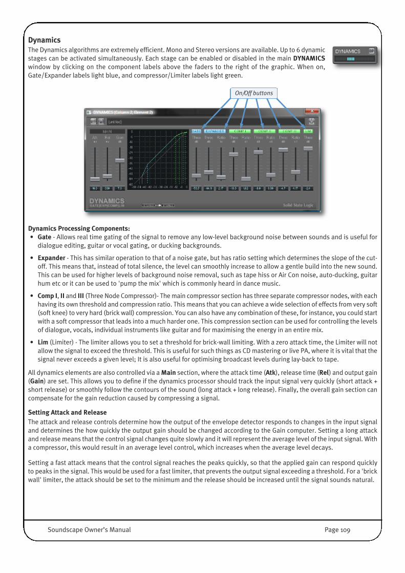
DynamicsThe Dynamics algorithms are extremely efficient. Mono and Stereo versions are available. Up to 6 dynamicstages can be activated simultaneously. Each stage can be enabled or disabled in the main DYNAMICSwindow by clicking on the component labels above the faders to the right of the graphic. When on,Gate/Expander labels light blue, and compressor/Limiter labels light green.
Dynamics Processing Components:• Gate - Allows real time gating of the signal to remove any low-level background noise between sounds and is useful for
dialogue editing, guitar or vocal gating, or ducking backgrounds.
• Expander - This has similar operation to that of a noise gate, but has ratio setting which determines the slope of the cut-off. This means that, instead of total silence, the level can smoothly increase to allow a gentle build into the new sound.This can be used for higher levels of background noise removal, such as tape hiss or Air Con noise, auto-ducking, guitarhum etc or it can be used to 'pump the mix' which is commonly heard in dance music.
• Comp I, II and III (Three Node Compressor)- The main compressor section has three separate compressor nodes, with eachhaving its own threshold and compression ratio. This means that you can achieve a wide selection of effects from very soft(soft knee) to very hard (brick wall) compression. You can also have any combination of these, for instance, you could startwith a soft compressor that leads into a much harder one. This compression section can be used for controlling the levelsof dialogue, vocals, individual instruments like guitar and for maximising the energy in an entire mix.
• Lim (Limiter) - The limiter allows you to set a threshold for brick-wall limiting. With a zero attack time, the Limiter will notallow the signal to exceed the threshold. This is useful for such things as CD mastering or live PA, where it is vital that thesignal never exceeds a given level; It is also useful for optimising broadcast levels during lay-back to tape.
All dynamics elements are also controlled via a Main section, where the attack time (Atk), release time (Rel) and output gain(Gain) are set. This allows you to define if the dynamics processor should track the input signal very quickly (short attack +short release) or smoothly follow the contours of the sound (long attack + long release). Finally, the overall gain section cancompensate for the gain reduction caused by compressing a signal.
Setting Attack and ReleaseThe attack and release controls determine how the output of the envelope detector responds to changes in the input signaland determines the how quickly the output gain should be changed according to the Gain computer. Setting a long attackand release means that the control signal changes quite slowly and it will represent the average level of the input signal. Witha compressor, this would result in an average level control, which increases when the average level decays.
Setting a fast attack means that the control signal reaches the peaks quickly, so that the applied gain can respond quicklyto peaks in the signal. This would be used for a fast limiter, that prevents the output signal exceeding a threshold. For a 'brickwall' limiter, the attack should be set to the minimum and the release should be increased until the signal sounds natural.
On/Off buttons
Soundscape Owner’s Manual Page 109

Setting a fast release means that the control signal responds quickly to a decay in the input level, so the gain can be increasedimmediately to compensate. The attack time should be increased until the signal sounds natural.
NOTE: Setting both attack and release too fast will distort the signal, as the gain applied can change with the waveformof the input signal.
The Atk and Rel faders have ranges of 0ms to 999.9ms for Attack, and 1ms to 9999ms for Release. The Gain fader allows thecurve to be positioned in the available dynamic range, changing the output level by up to +/-36dB.
Setting Thresholds and RatiosThere are 10 faders for setting thresholds and ratios for a Gate, an Expander, three separate Compressors and a Limiter.These allow very flexible control of the Compression Curve , which determines the transfer function between input and outputlevels.
Depending on the number and type of processing stages activated, any curve shape can be defined, including ‘soft knee’ and‘hard knee’ compressors and expanders, gates and limiters, or any combination of these.
The Thres (threshold) fader for each processor can be set from 0dB to -60dB and determines where the processor starts tokick in.
The Ratio fader for each processor sets the slope of the compressor curve (below the threshold for the Expander and abovethe threshold for each one of the 3 Compressors), from 1:1 to 1:50 (for expansion) or 50:1 (for compression), and determinethe gain change to be applied at the measured control signal level.
NOTE: The measurement of the input signal depends on the Attack and Release settings and higher values will slowdown the animated gain indicator on the curve.
The thresholds levels for the six processing stages need to increase from left to right. For example, the threshold for the gatecan not be higher than the threshold for the limiter. Therefore, if a threshold fader is moved up and reaches a current positionof another threshold fader to its right, this fader will also start moving up. �
If a threshold fader is moved down and reaches the position of another threshold fader to its left, thisfader will also start moving down. However, as long as the mouse button has not been released,returning the fader towards its original position will allow the other threshold settings to be restored.
Moving any threshold fader with the right mouse button will move all other threshold fadersrelatively, while maintaining the dB relationship. This allows the whole curve to be shifted up ordown in the graph.
For the Gate and Expander, when the control signal is below the threshold the signal is muted, onlyabove the threshold the ‘Gate’ is opened and audio passes through.
Process MeterThe amount of gain reduction is shown by the meter in the Dynamicsmixer element. The meter calibration is 3dB per segment.
In the main Dynamics window, the level of the processed signal isshown in the curve display as a white ‘+’ sign that moves in real time along the curve. This makes it easy to check whetherthe signal is operating at the correct point on the curve. The level of the input signal level is shown as a small vertical whiteline which moves along the horizontal axis .
No Processing Expansion/Gate Compression
Page 110 Soundscape Owner’s Manual

DelayThe Delay plug-in provides a 2-tap mono, 2-tapmono to stereo, or 2-tap stereo delay, withselectable cross-linking between left and right
channels. Each can be a Long, Medium or Short delay.
As longer delays need more DSP Memory, it is advisable to selectthe element type with the shortest delay time that suits yourrequirements.
For example, at 44.1kHz:• Long: up to 1088.4ms• Medium: up to 544.2ms• Short: up to 272.1ms
The CROSS or NORMAL button on a stereo delay defines whetherthe feedback portion of left and right delay are ‘cross-coupled’ forpanning delay effects. When CROSS mode is active, the feedbacksignal from the left delay line is fed into the input of the right delayline and vice versa.
Stereo delay plug-ins feature completely independent controls forthe Left and Right Delay Lines.
DitherThe Dither element can be used when lowering the audio’s bit resolution. It provides the ability to extend the dynamic rangeand include some of the low level detail of the audio signal that would otherwise be truncated and therefore lost. It providesRectangular and Triangular dithering, with Noise shaping capability.
For instance, when multiple 24 bit tracks are mixed to stereo and the result isrequired for CD at 16 bits, the Dither element would normally be placed in the mainstereo output channel strip. The recording resolution and the Dither Requantisationbit depth would then both be set to 16 bit.
The Requantization bit depth can be changed in the value box using the mousebuttons in the usual way. Alternatively, double-clicking in the value box will opena text entry dialogue.
Soundscape Owner’s Manual Page 111

Using VST Plug-InsVST effect plug-ins running on the host CPU can be inserted in the Soundscape Mixer just like any other mixer element. VSTplug-ins are stored with a ‘dll’ extension. For a VST plug-in to be available to the SSL Mixer, the corresponding dll file mustbe loaded by Soundscape during startup.
By default, the Soundscape scans the ‘C:\Program Files\Soundscape\MixElem\VST’ folder and loads the dll files located inthat folder. A different path can be specified by adding a ‘VSTLibPath=’ line to the file ssEditordef.ini file (located inC:\Soundscape), for instance: ‘VSTLibPath=C:\Program Files\Steinberg\Vstplugins\’. You can open and save .INI files withNotepad.exe. Note that any subfolders of the designated folder will be scanned as well.
During scanning, a small window appears in front of the splashcreenwhere the plug-in names are displayed as they are loaded.
Dialogue boxes may also appear during that phase, for instance whena plug-in requires authorisation.
NOTE: In rare cases VST plug-ins may not be loaded, because their ‘unique ID’ conflicts with the ‘unique ID’ of an alreadyloaded SSL Mixer element. In such cases a warning message will be displayed.
Since VST plug-ins run on the CPU of the host PC, the audio must be routed at high speed between the SSL Mixer and the PCin order to use VST effects at low latencies. This is done using the ‘streams’ provided by the MX4 or Mixpander. One streamis used per channel of audio, meaning a mono VST plug-in uses one stream and a stereo VST plug-in uses two streams.However, stream usage has been optimised so that consecutive VST plug-ins in the same mixer strip only require Inputstreams for the first VST Plug-In and Output Streams for the last VST Plug-in inside the chain. Therefore, as long as the signaldoes not leave ‘PC Land’ or ‘DSP Land’, no additional streams need to be set up to connect both worlds.
NOTE: Track Elements are also inside ‘PC Land’, therefore a Track followed by a VST Plug-In only uses I/O streams once.
Available streams are assigned automatically to VST plug-ins, takinginto account that streams already used by a Windows application orassigned to a mixer input, output or send element are not available.If the number of available streams becomes insufficient for thenumber of VST plug-ins being used, the following warning will bedisplayed.
In this case the Mixer will also become inactive until the situation isresolved by deleting one or more VST plug-in(s), reassigning ormuting one or more input, output or send element(s) or closing or re-routing a Windows application in order to release some streams.
The default buffer size for native mixer elements is 128 samples. Thissetting determines the ‘latency’ of the VST calculation. It can bechanged in the Settings/ Preferences / Mixer / Native mixerelements Sample Buffer Size menu.
Typically, it should be raised if the PC is struggling to cope with theprocessing demands. Multiples of 64 up to 8192 can be used. If aninvalid value is entered, the closest valid value below it will be usedinstead.
Page 112 Soundscape Owner’s Manual
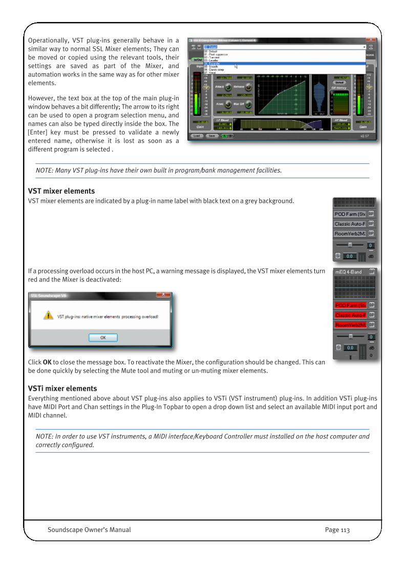
Operationally, VST plug-ins generally behave in asimilar way to normal SSL Mixer elements; They canbe moved or copied using the relevant tools, theirsettings are saved as part of the Mixer, andautomation works in the same way as for other mixerelements.
However, the text box at the top of the main plug-inwindow behaves a bit differently; The arrow to its rightcan be used to open a program selection menu, andnames can also be typed directly inside the box. The[Enter] key must be pressed to validate a newlyentered name, otherwise it is lost as soon as adifferent program is selected .
NOTE: Many VST plug-ins have their own built in program/bank management facilities.
VST mixer elementsVST mixer elements are indicated by a plug-in name label with black text on a grey background.
If a processing overload occurs in the host PC, a warning message is displayed, the VST mixer elements turnred and the Mixer is deactivated: �
Click OK to close the message box. To reactivate the Mixer, the configuration should be changed. This canbe done quickly by selecting the Mute tool and muting or un-muting mixer elements.
VSTi mixer elementsEverything mentioned above about VST plug-ins also applies to VSTi (VST instrument) plug-ins. In addition VSTi plug-inshave MIDI Port and Chan settings in the Plug-In Topbar to open a drop down list and select an available MIDI input port andMIDI channel.
NOTE: In order to use VST instruments, a MIDI interface/Keyboard Controller must installed on the host computer andcorrectly configured.
�
Soundscape Owner’s Manual Page 113

Additional information regarding VST/VSTi plug-in compatibilityCertain VST or VSTi plug-ins require special Multi-Threading settings to work in the SSL Mixer environment. Typically whenlaunching the SSL Mixer application ‘problematic’ plug-ins would cause an ‘object initialization’ error and the program wouldimmediately close again. The ‘-a’ command line switch solves the problem by initialising COM objects as‘APPARTMENT_THREADED’ instead of ‘MULTI_THREADED’.
To use the ‘-a’ command switch, insert -a just after SrEditor.exe in the Target line of the Soundscape shortcut’s properties.
In a standard installation, the SSL Soundscape V6.xx shortcut is located on your desktop. Right-clicking the shortcut willopen the Properties window. The edited line should read as follows:
C:\Program Files\Soundscape\Version 6.xx\Sreditor.exe" -a /h ssEditorDef.ini
NOTE: Using this command line switch may slow down the performance of the SSL Console Manager application.
‘-a’ command line switch
Page 114 Soundscape Owner’s Manual

Automatic Delay Compensation (ADC)In a digital mixing system, any audio processing a certain amount of time, known as a processing delay. When several signalsare processed in parallel (for instance a kick drum going through a compressor in a mixer column and a bass going througha compressor, an EQ and a chorus in an other mixer column), the cumulative delay for each signal may be different, resultingin ‘misaligned’ audio signals. Phase problems may also be created.
These problems can be solved by introducing compensating delays in some of the signal paths to get the output audio signalsperfectly aligned. However, this introduces another problem: since all the signals must be aligned with the ‘slowest’ one(i.e., the one that sustains the highest cumulated processing delay), any signal going through the system is delayed, eitherby a processing delay or by a compensating delay. A performer cannot, therefore, monitor their performance in real-timethrough that system.
A benefit of DSP-powered systems such as MX4 and Mixpander is that the processing delays are in most cases negligible,comparable to those of hardware digital mixers and effects units. In fact, MX4 and Mixpander are indeed hardware systems,controlled via a software interface.
On the other hand, native systems that use the CPU of the host PC are subject to higher processing delays inherent to the PCenvironment, which requires the use of buffers for reliable audio processing, even for the most basic effect plug-in.
VST compatibility offers SSL Mixer users a very wide choice of plug-ins. However, since VST plug-ins inserted in the SSL Mixerrun on the CPU of the host PC, buffers must be used. The Automatic Delay Compensation takes care of the resulting alignmentand phase problems.
Note that in recording situations, when real-time monitoring of the input signals is required, it may be preferable to use onlyDSP-powered plug-ins, with or without Automatic Delay Compensation. VST plug-ins can then be used when mixing,preferably with Automatic Delay Compensation active. The Automatic Delay Compensation (ADC) function can introducecompensating delays in the Mixer in order to counter the effects of any mixer element and bus delays. The ADC compensatesfor all bus and output delays. This means that the audio paths leading to common points are ‘lined up’ (i.e., they present thesame overall amount of delay). However, all buses and outputs are not necessarily lined up relative to each other.
For instance, the following output pairs are not lined up by default if they have completely isolated audio paths in the Mixer.They will only be lined up relative to each other if they are referenced by the same send or output element:• MADI1-2 U1, used by the ‘Output (Stereo)’ element in mixer column 1• MADI3-4 U1, used by the ‘Output (Stereo)’ element in mixer column 2
Automatic Delay Compensation toggle [Ctrl]+[Alt]+[D]
Automatic Delay Compensation toggleThe Automatic Delay Compensation can be activated or deactivated byclicking the adc toggle, located in the bottom right corner of the Mixerwindow.
Automatic Delay Compensation is active when the button is highlighted.
Alternatively, you can click Automatic Delay Compensation toggle inthe Edit menu, or use the [Ctrl]+[Alt]+[D] key command.
Automatic Delay
Compensation disabled
Automatic Delay
Compensation enabled
Soundscape Owner’s Manual Page 115

ADC PreferencesSoundscape offers several options andstrategies on how to compensate forprocessing delays.
The Options are centralised in the Settings / Preferences / Mixer / If Automatic Delay Compensation is active menu.
Shift Audio Tracks to compensate for individual track mixer delayIf this option is enabled, ADC shifts some of the audio Parts to the left (so that they will be played back early) whereappropriate, before inserting delays in the Mixer.
This presents two advantages:• The overall delay may be shorter, since only the delays caused by mixer elements placed below track inserts in the signal
path need to be neutralised• The ADC function will use less DSP and Memory resources to carry out its calculations
NOTES:The fact that certain Parts are played early is not reflected graphically by their position in the Arrangement. The ADC is not 100% accurate while scrubbingAudio playback may not start simultaneously for all audio tracks, due to the differing track delays.The first samples placed at the beginning of the Arrangement for Audio Parts that are played early, are skipped. This option is ignored when the Mixdown tool is used, which has its own strategy to compensate processing delays.
Shift entire Arrangement to compensate for maximum mixer delayIf this option is enabled, the entire Arrangement is internally shifted ‘to the left’ (i.e. to an earlier time position) to compensatefor the maximum output delay in the mixer.
NOTE: When this option is enabled, the first samples at the beginning of the arrangement are skipped. Therefore, whenADC is active and this option is enabled, it is best to not place any audio at the very beginning of the arrangement.
Align all Output elements with fader In order to line up outputs that have isolated audio paths in the Mixer, this option can be used. When selected, all outputelements that have an Output fader are lined up. Outputs elements without a fader can be used for signals that should notbe lined up (e.g., a send or Column without fader feeding the artist monitor, Send/Return Path to an external FX processor,etc.).
Align all Output elements, except if followed by Input elementEnabling this option will line up all the output elements, except those that are followed by an Input element. This is especiallyuseful, when the Output-Input Element Path is used as an Insert/Return for Outboard processors.
Page 116 Soundscape Owner’s Manual

Mixer element Delay Adjustment parameterThe ADC function relies on the delay values reported by each individual mixer element to calculate the compensating delaysthat must be applied. This value can be checked and edited by the user.
In Mix Edit mode, clicking a mixer element with the Info toolwill open the corresponding Element Info window, as shown
right for a TC Reverb plug-in.
The value in the Delay Adjustment (+/-) field will be added to orsubtracted from the Reported delay value.
Any value (in samples) up to 99999 can be entered (more than shouldever be needed).
For a negative value the minus sign must be entered. There is no needto type the plus sign for a positive value.
Note that this parameter is applied individually for each instance of a mixer element, allowing you to selectively correct orintroduce a delay in the Mixer when ADC is active. The Delay Adjustment parameter setting is saved as part of the Mixer.
If you find that the reported delay value always needs to be adjusted by the same amount for each instance of a particularmixer element, you can override the reported delay value by adding a command line to that effect in the [MixWnd] section ofthe ssEditorDef.ini file (the path to the .INI file can be checked by right-click on Soundscape Shortcut / Properties, in the Startin field).
The ADC will ignore the value of the Reported delay parameter shown in the Element Info window and will use the valuespecified by the command line in its calculations, taking the Delay Adjustment parameter into account.
NOTE: Soundscape must be restarted for the command line to take effect (settings specified in the .INI file are loadedon startup).
The command line reads as follows:
ElemType XXXXXXXX Delay=Y // Element’s name
where XXXXXXXX is the unique Element Type ID for the element, andY is the required delay value in samples. The ‘Element’s name’ is onlyrequired for documentation purposes.
To check the Element Type ID, in Mix Edit mode, hold down the [Shift]key and click the mixer element with the Info tool. The ElementProperties window for that mixer element will be displayed, asshown for the TC Reverb. The Element Type ID is displayed on thesecond line (red circle).
To continue with the same example, in order to specify a delay valueof 45 for the TC Reverb stereo mixer element, the command line inthe [MixWnd] section of the .INI file should read:
ElemType 2049 Delay=45 // TC Reverb (Stereo)
Soundscape Owner’s Manual Page 117

MIXER AUTOMATIONThe Automation reflects the general philosophy of Soundscape: it is flexible, powerful, easy to use and user configurable.Automation recording is in many ways similar to audio recording, and has been explained to some degree in the ‘RecordingAutomation’ section of Chapter 3. A reminder of the main points, plus some information specific to automation recordingwhich was not mentioned, will be provided in the ‘Automation recording’ section of this chapter. ‘Snapshot’ automationrecording will also be described.
Automation can be used easily with its default settings. However, these can be changed, so that for example you could recordall the automation data for a whole Arrangement on one single automation track instead of using one automation track permixer column. The ‘Automation Setup window’ and ‘Info tool’ sections of this chapter will provide all the information you needto customise the operation of the automation system to suit your preferences.
The ‘Automation concepts and mixer controls behaviour’ section expands on certain basic concepts and features of theautomation system and their practical implications.
Recorded automation data can be viewed and edited ‘offline’ with three specific tools which will be described in the‘Automation editing’ section.
Some vocabulary specific to Automation will be used in this chapter. Automation data is made of ‘automation events’, andthese come in two varieties: ‘continuous events’ and ‘stepped events’. The difference will be explained in the ‘AutomationEvent Editing tool’ section. ‘Automation events’ are generated whenever an automatable mixer ‘knob’ is used, and ‘knob’ isused as a generic term to cover all mixer controls, from faders and sliders to pots and buttons.
Enabling AutomationFor any automation data to be recorded or played back, theAutomation must be enabled. This can be done by clicking theAutomation Enable toggle which is located in the bottom, rightcorner of the Mixer window. Automation is active when thebutton is highlighted (blue):
Alternatively, you can press [G] on the computer keyboard toenable/disable Automation, but only when the Mixer window isopen, or click Automation Enable toggle in the Edit menu.
Automation recordingAutomation can be recorded ‘dynamically’. In this case, each time a knob is used, a corresponding ‘automation event’ isrecorded in an automation Part. Automation can also be recorded ‘statically’ using the Snapshot function. In this case, thesettings of the mixer elements at the time the Snapshot Automation Record button is clicked are recorded.
Dynamic automation recordingAutomation is recorded as Parts in the Arrangement which reference Takes on the disk, in muchthe same way as audio. 128 automation tracks are available, and each track can containautomation data for several mixer elements. By default, the automation data for all the elementsin a mixer slot (including the mixer column itself and all the ‘plug-in’ mixer elements) is recordedon the automation track of which the number matches the mixer slot number.
Mixer Slot Number
Enable Automation
Status: Disabled
Enable Automation
Status: Enabled
Page 118 Soundscape Owner’s Manual

In order to record automation, an automation record trackneeds to be created by right-clicking in the Record TrackColumn:
It must then be armed using the track arming button, asdescribed in detail in the ‘Automation recording’ sectionof Chapter 3.
The procedures for audio recording apply to automation recording as well, with a few exceptions. For example, automationtracks cannot be armed from inside the Mixer or using the computer keyboard. However, loop recording, record loop stacks,manual punch in/out, and the Auto Punch In/Out mode can all be used for automation recording.
WARNING: Unlike audio Parts, automation Parts can contain several layers of data (automation curves). Simplypunching-in on an automation Part (in Normal Record mode) will overwrite all the data in the ‘punched’ section of thisPart (i.e., all the automation curves are affected). The ‘Touch Record’ mode or ‘Touch Record Till Stop’ mode should beselected for automation punch in/out with no risk of losing any data.
Automation Record ModesThere are three automation recording modes: Normal Record, Touch Record, andTouch Record Till Stop. These are selected in the Automation Setup window,accessed via the Settings / Automation Setup menu. The default setting is NormalRecord.
Normal RecordIn this mode only the automation events generated during the current pass are recorded. If you are recording over an existingPart (or any section of a Part) on the same virtual track, this Part (or section of a Part) is overwritten. Overwriting a Part thatcontains several automation curves means that all the curves are overwritten regardless of which one is displayed, so greatcare should be taken when overwriting an existing automation Part. However, the Take referenced by the overwritten Partwill be preserved on the disk. Normal Record would typically be used to record a new automation Part from scratch or whenan existing Part needs to be replaced.
Touch RecordIn this mode, the automation events generated during the current pass are recorded, and all automation events from existingactive Parts assigned to the same automation track are re-recorded to the new Part as well. Therefore, it is possible tooverwrite an existing Part (or section of a Part) on the same virtual track, yet re-record all the data it contains at the same timeas long as that existing Part is active when recording is started.
The knobs will respond to the automation data in existing active Parts. However you can grab them at any time to startgenerating and recording new data, with the mouse or using a control surface. When a knob is released, it starts respondingagain to the existing automation data, taking into account the settings of the Knob auto return time and Knob touch timeoutparameters in the Automation Setup window (as described in the ‘Automation Setup window’ section which is next in thischapter).
Touch Record would typically be used as a ‘multiple punch in/out mode’ for automation Parts (a punch in is performed eachtime a knob assigned to the automation track being recorded is grabbed, and a punch out is performed each time such a knobis released).
Automation Track (disarmed)
Automation Track (armed)
Soundscape Owner’s Manual Page 119

Touch Record Till StopIn this mode, as in Touch Record, the automation events generated during the current pass are recorded, and all automationevents from existing active Parts assigned to the same track are re-recorded to the new Part as well. However, unlike TouchRecord, when a knob is released, it does not start responding again to existing automation data. Instead, this data isoverwritten until recording is stopped.
Touch Record Till Stop would typically be used as a multiple punch-in mode for automation Parts, for cases when only thebeginning of the existing automation curve(s) needs to be preserved.
NOTE: Everything that has been described here applies in the same way when several automation record tracks areused at the same time.
Cycle End ModeIf the Apply last recorded value from Part begin (Cycle End mode) option is active (box checked), when recording is stopped,the last automation event recorded for each mixer knob during the last pass is shifted to the beginning of the automation Part,where it is placed immediately after the automation event representing the value for the knob at the beginning of that Part.All other automation events recorded during that pass are discarded.
Snapshot automation recordingAll the current settings for one or more mixer columns can also be recorded as a snapshot byclicking the Snapshot Automation Record button, located near the Automation Enable togglein the bottom right corner of the Arrange window. Alternatively, press the [F] key or clickSnapshot Automation Record under the Edit menu.
The resulting snapshot shows as an automation Part or group of Parts which starts at the timeposition where the Snapshot Automation Record button was clicked. One Part is generated foreach armed automation record track, which contains information for the setting of each enabledautomatable knob assigned to that track.
To record a snapshot for the whole mixer, one automation record track should first be created and armed for each mixer slotthat contains a mixer column (unless the default settings are modified as described in the ‘Info tool’ section of this chapter).
The Snapshot Automation Record button can also be used during dynamic automation recording. In this case, the Parts willnot start at the time position where the snapshot was made, (because that was by definition after the start of the recording),but all the snapshot data will be contained in the Parts at the time position where the snapshot was made.
The data recorded in a snapshot is also dependent on the settings chosen in the Automation Setup window, as described inthe next section.
Snaphot Automation
Record button
Page 120 Soundscape Owner’s Manual
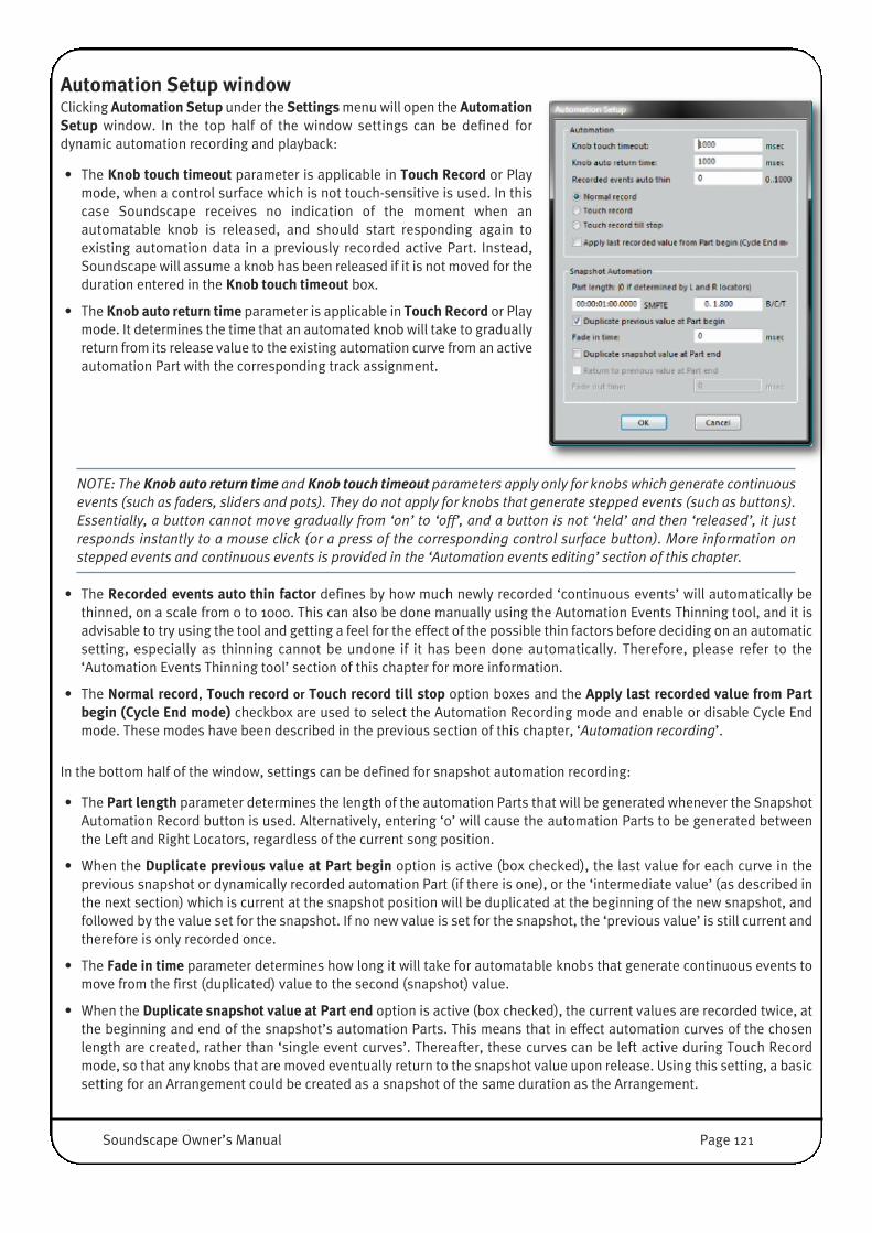
Automation Setup window Clicking Automation Setup under the Settings menu will open the AutomationSetup window. In the top half of the window settings can be defined fordynamic automation recording and playback:
• The Knob touch timeout parameter is applicable in Touch Record or Playmode, when a control surface which is not touch-sensitive is used. In thiscase Soundscape receives no indication of the moment when anautomatable knob is released, and should start responding again toexisting automation data in a previously recorded active Part. Instead,Soundscape will assume a knob has been released if it is not moved for theduration entered in the Knob touch timeout box.
• The Knob auto return time parameter is applicable in Touch Record or Playmode. It determines the time that an automated knob will take to graduallyreturn from its release value to the existing automation curve from an activeautomation Part with the corresponding track assignment.
NOTE: The Knob auto return time and Knob touch timeout parameters apply only for knobs which generate continuousevents (such as faders, sliders and pots). They do not apply for knobs that generate stepped events (such as buttons).Essentially, a button cannot move gradually from ‘on’ to ‘off’, and a button is not ‘held’ and then ‘released’, it justresponds instantly to a mouse click (or a press of the corresponding control surface button). More information onstepped events and continuous events is provided in the ‘Automation events editing’ section of this chapter.
• The Recorded events auto thin factor defines by how much newly recorded ‘continuous events’ will automatically bethinned, on a scale from 0 to 1000. This can also be done manually using the Automation Events Thinning tool, and it isadvisable to try using the tool and getting a feel for the effect of the possible thin factors before deciding on an automaticsetting, especially as thinning cannot be undone if it has been done automatically. Therefore, please refer to the‘Automation Events Thinning tool’ section of this chapter for more information.
• The Normal record, Touch record or Touch record till stop option boxes and the Apply last recorded value from Partbegin (Cycle End mode) checkbox are used to select the Automation Recording mode and enable or disable Cycle Endmode. These modes have been described in the previous section of this chapter, ‘Automation recording’.
In the bottom half of the window, settings can be defined for snapshot automation recording:
• The Part length parameter determines the length of the automation Parts that will be generated whenever the SnapshotAutomation Record button is used. Alternatively, entering ‘0’ will cause the automation Parts to be generated betweenthe Left and Right Locators, regardless of the current song position.
• When the Duplicate previous value at Part begin option is active (box checked), the last value for each curve in theprevious snapshot or dynamically recorded automation Part (if there is one), or the ‘intermediate value’ (as described inthe next section) which is current at the snapshot position will be duplicated at the beginning of the new snapshot, andfollowed by the value set for the snapshot. If no new value is set for the snapshot, the ‘previous value’ is still current andtherefore is only recorded once.
• The Fade in time parameter determines how long it will take for automatable knobs that generate continuous events tomove from the first (duplicated) value to the second (snapshot) value.
• When the Duplicate snapshot value at Part end option is active (box checked), the current values are recorded twice, atthe beginning and end of the snapshot’s automation Parts. This means that in effect automation curves of the chosenlength are created, rather than ‘single event curves’. Thereafter, these curves can be left active during Touch Recordmode, so that any knobs that are moved eventually return to the snapshot value upon release. Using this setting, a basicsetting for an Arrangement could be created as a snapshot of the same duration as the Arrangement.
Soundscape Owner’s Manual Page 121
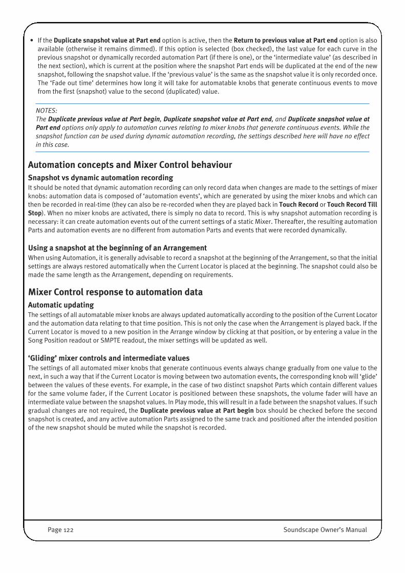
• If the Duplicate snapshot value at Part end option is active, then the Return to previous value at Part end option is alsoavailable (otherwise it remains dimmed). If this option is selected (box checked), the last value for each curve in theprevious snapshot or dynamically recorded automation Part (if there is one), or the ‘intermediate value’ (as described inthe next section), which is current at the position where the snapshot Part ends will be duplicated at the end of the newsnapshot, following the snapshot value. If the ‘previous value’ is the same as the snapshot value it is only recorded once.The ‘Fade out time’ determines how long it will take for automatable knobs that generate continuous events to movefrom the first (snapshot) value to the second (duplicated) value.
NOTES: The Duplicate previous value at Part begin, Duplicate snapshot value at Part end, and Duplicate snapshot value atPart end options only apply to automation curves relating to mixer knobs that generate continuous events. While thesnapshot function can be used during dynamic automation recording, the settings described here will have no effectin this case.
Automation concepts and Mixer Control behaviourSnapshot vs dynamic automation recordingIt should be noted that dynamic automation recording can only record data when changes are made to the settings of mixerknobs: automation data is composed of ‘automation events’, which are generated by using the mixer knobs and which canthen be recorded in real-time (they can also be re-recorded when they are played back in Touch Record or Touch Record TillStop). When no mixer knobs are activated, there is simply no data to record. This is why snapshot automation recording isnecessary: it can create automation events out of the current settings of a static Mixer. Thereafter, the resulting automationParts and automation events are no different from automation Parts and events that were recorded dynamically.
Using a snapshot at the beginning of an ArrangementWhen using Automation, it is generally advisable to record a snapshot at the beginning of the Arrangement, so that the initialsettings are always restored automatically when the Current Locator is placed at the beginning. The snapshot could also bemade the same length as the Arrangement, depending on requirements.
Mixer Control response to automation dataAutomatic updatingThe settings of all automatable mixer knobs are always updated automatically according to the position of the Current Locatorand the automation data relating to that time position. This is not only the case when the Arrangement is played back. If theCurrent Locator is moved to a new position in the Arrange window by clicking at that position, or by entering a value in theSong Position readout or SMPTE readout, the mixer settings will be updated as well.
‘Gliding’ mixer controls and intermediate valuesThe settings of all automated mixer knobs that generate continuous events always change gradually from one value to thenext, in such a way that if the Current Locator is moving between two automation events, the corresponding knob will ‘glide’between the values of these events. For example, in the case of two distinct snapshot Parts which contain different valuesfor the same volume fader, if the Current Locator is positioned between these snapshots, the volume fader will have anintermediate value between the snapshot values. In Play mode, this will result in a fade between the snapshot values. If suchgradual changes are not required, the Duplicate previous value at Part begin box should be checked before the secondsnapshot is created, and any active automation Parts assigned to the same track and positioned after the intended positionof the new snapshot should be muted while the snapshot is recorded.
Page 122 Soundscape Owner’s Manual
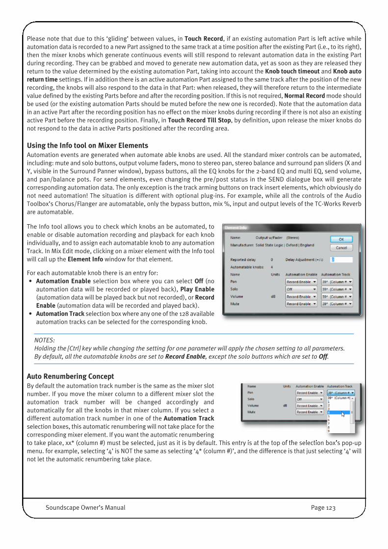
Please note that due to this ‘gliding’ between values, in Touch Record, if an existing automation Part is left active whileautomation data is recorded to a new Part assigned to the same track at a time position after the existing Part (i.e., to its right),then the mixer knobs which generate continuous events will still respond to relevant automation data in the existing Partduring recording. They can be grabbed and moved to generate new automation data, yet as soon as they are released theyreturn to the value determined by the existing automation Part, taking into account the Knob touch timeout and Knob autoreturn time settings. If in addition there is an active automation Part assigned to the same track after the position of the newrecording, the knobs will also respond to the data in that Part: when released, they will therefore return to the intermediatevalue defined by the existing Parts before and after the recording position. If this is not required, Normal Record mode shouldbe used (or the existing automation Parts should be muted before the new one is recorded). Note that the automation datain an active Part after the recording position has no effect on the mixer knobs during recording if there is not also an existingactive Part before the recording position. Finally, in Touch Record Till Stop, by definition, upon release the mixer knobs donot respond to the data in active Parts positioned after the recording area.
Using the Info tool on Mixer ElementsAutomation events are generated when automate able knobs are used. All the standard mixer controls can be automated,including: mute and solo buttons, output volume faders, mono to stereo pan, stereo balance and surround pan sliders (X andY, visible in the Surround Panner window), bypass buttons, all the EQ knobs for the 2-band EQ and multi EQ, send volume,and pan/balance pots. For send elements, even changing the pre/post status in the SEND dialogue box will generatecorresponding automation data. The only exception is the track arming buttons on track insert elements, which obviously donot need automation! The situation is different with optional plug-ins. For example, while all the controls of the AudioToolbox’s Chorus/Flanger are automatable, only the bypass button, mix %, input and output levels of the TC-Works Reverbare automatable.
The Info tool allows you to check which knobs an be automated, toenable or disable automation recording and playback for each knobindividually, and to assign each automatable knob to any automationTrack. In Mix Edit mode, clicking on a mixer element with the Info toolwill call up the Element Info window for that element.
For each automatable knob there is an entry for:• Automation Enable selection box where you can select Off (no
automation data will be recorded or played back), Play Enable(automation data will be played back but not recorded), or RecordEnable (automation data will be recorded and played back).
• Automation Track selection box where any one of the 128 availableautomation tracks can be selected for the corresponding knob.
NOTES: Holding the [Ctrl] key while changing the setting for one parameter will apply the chosen setting to all parameters.By default, all the automatable knobs are set to Record Enable, except the solo buttons which are set to Off.
Auto Renumbering ConceptBy default the automation track number is the same as the mixer slotnumber. If you move the mixer column to a different mixer slot theautomation track number will be changed accordingly andautomatically for all the knobs in that mixer column. If you select adifferent automation track number in one of the Automation Trackselection boxes, this automatic renumbering will not take place for thecorresponding mixer element. If you want the automatic renumberingto take place, xx* (column #) must be selected, just as it is by default. This entry is at the top of the selection box’s pop-upmenu. for example, selecting ‘4’ is NOT the same as selecting ‘4* (column #)’, and the difference is that just selecting ‘4’ willnot let the automatic renumbering take place.
Soundscape Owner’s Manual Page 123

However, please note that if you move a mixer column to a different mixer slot and the automatic renumbering is enabled,any existing automation Part for that mixer column will need to be reassigned to a new track. This can be done by clicking onthe Part in the Arrange window with the Info tool to open the Part Info window and changing the Output parameter, or byclicking on the Part with the Track Assign tool.
In most cases the default settings are perfectly adequate. You may want to change them for example to save space on-screenby recording automation for several mixer columns on one single track, if you need a lot of virtual tracks for audio Parts.
The Info tool can also be used in the Arrange window to check and edit information for automation Parts. In particular, it ispossible to choose which automation curve will be displayed (this is also the function of the Automation Curve Select tool),and to reassign an automation Part to a different automation track for playback (for example in order to direct the data fromthat Part to different mixer elements, or perhaps to equivalent mixer elements in a different mixer column, all depending oncurrent settings).
Automation editingAutomation Parts can be treated in many respects just like Audio Parts. They can for example be moved, copied, cut, muted,assigned (to automation tracks), or deleted with the same editing tools as Audio Parts. However, ‘Automation Events’ withinthe Parts can also be viewed and edited with three specific tools: ‘Automation Curve Select’, ‘Automation Events Thinning’and ‘Automation Event Editing’. They have been mentioned briefly in the ‘Editing Tools’ section of this manual, but will beexamined in detail here:
Automation Curve Select toolAn automation Part can contain many different layers of
recorded data, generated by using the Mixer or adjusting plug-inparameters. This could include volume fader movements, mutes,reverb output level changes, etc. However, these automationParts can only display one single layer of automation data,relating to one single knob, at any time. The ‘layers’ of dataappear as ‘automation curves’, and the Automation Curve Selecttool allows you to select which curve is displayed and thereforeaccessible for editing. Click on an automation Part with the‘Automation Curve Select’ tool (also accessed by pressing[Ctrl]+[Shift]+[A]), and a menu will appear which lists all theautomation curves contained in the Part. Hold the mouse buttondown, move the pointer to the desired entry in the menu andrelease the mouse button to switch to the chosen curve.
The Automation Curve Select tool can also be used on a group ofselected Parts, but the menu will only show the entries relevantto the Part you click on, and any selected Parts that do not containcorresponding data will not respond.
NOTE: The name of the currently displayed automation curve is automatically appended to the end of the Part name,which is visible if you have enabled Show Part name in waveform under the Settingsmenu.
Page 124 Soundscape Owner’s Manual
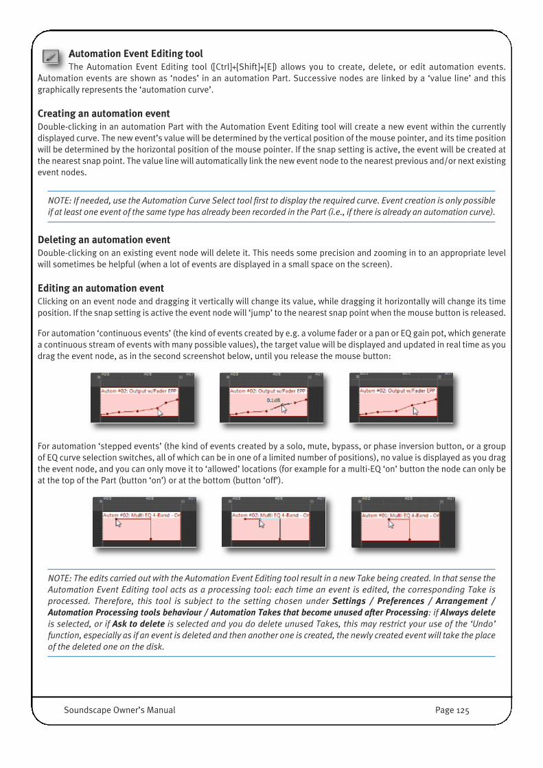
� Automation Event Editing toolThe Automation Event Editing tool ([Ctrl]+[Shift]+[E]) allows you to create, delete, or edit automation events.
Automation events are shown as ‘nodes’ in an automation Part. Successive nodes are linked by a ‘value line’ and thisgraphically represents the ‘automation curve’.
Creating an automation eventDouble-clicking in an automation Part with the Automation Event Editing tool will create a new event within the currentlydisplayed curve. The new event’s value will be determined by the vertical position of the mouse pointer, and its time positionwill be determined by the horizontal position of the mouse pointer. If the snap setting is active, the event will be created atthe nearest snap point. The value line will automatically link the new event node to the nearest previous and/or next existingevent nodes.
NOTE: If needed, use the Automation Curve Select tool first to display the required curve. Event creation is only possibleif at least one event of the same type has already been recorded in the Part (i.e., if there is already an automation curve).
Deleting an automation eventDouble-clicking on an existing event node will delete it. This needs some precision and zooming in to an appropriate levelwill sometimes be helpful (when a lot of events are displayed in a small space on the screen).
Editing an automation eventClicking on an event node and dragging it vertically will change its value, while dragging it horizontally will change its timeposition. If the snap setting is active the event node will ‘jump’ to the nearest snap point when the mouse button is released.
For automation ‘continuous events’ (the kind of events created by e.g. a volume fader or a pan or EQ gain pot, which generatea continuous stream of events with many possible values), the target value will be displayed and updated in real time as youdrag the event node, as in the second screenshot below, until you release the mouse button:
For automation ‘stepped events’ (the kind of events created by a solo, mute, bypass, or phase inversion button, or a groupof EQ curve selection switches, all of which can be in one of a limited number of positions), no value is displayed as you dragthe event node, and you can only move it to ‘allowed’ locations (for example for a multi-EQ ‘on’ button the node can only beat the top of the Part (button ‘on’) or at the bottom (button ‘off’).
�
NOTE: The edits carried out with the Automation Event Editing tool result in a new Take being created. In that sense theAutomation Event Editing tool acts as a processing tool: each time an event is edited, the corresponding Take isprocessed. Therefore, this tool is subject to the setting chosen under Settings / Preferences / Arrangement /Automation Processing tools behaviour / Automation Takes that become unused after Processing: if Always deleteis selected, or if Ask to delete is selected and you do delete unused Takes, this may restrict your use of the ‘Undo’function, especially as if an event is deleted and then another one is created, the newly created event will take the placeof the deleted one on the disk.
�
Soundscape Owner’s Manual Page 125
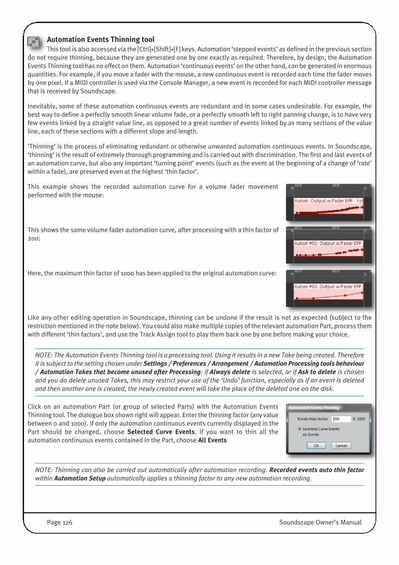
Automation Events Thinning toolThis tool is also accessed via the [Ctrl]+[Shift]+[F] keys. Automation ‘stepped events’ as defined in the previous section
do not require thinning, because they are generated one by one exactly as required. Therefore, by design, the AutomationEvents Thinning tool has no effect on them. Automation ‘continuous events’ on the other hand, can be generated in enormousquantities. For example, if you move a fader with the mouse, a new continuous event is recorded each time the fader movesby one pixel. If a MIDI controller is used via the Console Manager, a new event is recorded for each MIDI controller messagethat is received by Soundscape.
Inevitably, some of these automation continuous events are redundant and in some cases undesirable. For example, thebest way to define a perfectly smooth linear volume fade, or a perfectly smooth left to right panning change, is to have veryfew events linked by a straight value line, as opposed to a great number of events linked by as many sections of the valueline, each of these sections with a different slope and length.
‘Thinning’ is the process of eliminating redundant or otherwise unwanted automation continuous events. In Soundscape,‘thinning’ is the result of extremely thorough programming and is carried out with discrimination. The first and last events ofan automation curve, but also any important ‘turning point’ events (such as the event at the beginning of a change of ‘rate’within a fade), are preserved even at the highest ‘thin factor’.
This example shows the recorded automation curve for a volume fader movementperformed with the mouse:
This shows the same volume fader automation curve, after processing with a thin factor of200:
Here, the maximum thin factor of 1000 has been applied to the original automation curve:
Like any other editing operation in Soundscape, thinning can be undone if the result is not as expected (subject to therestriction mentioned in the note below). You could also make multiple copies of the relevant automation Part, process themwith different ‘thin factors’, and use the Track Assign tool to play them back one by one before making your choice.
NOTE: The Automation Events Thinning tool is a processing tool. Using it results in a new Take being created. Thereforeit is subject to the setting chosen under Settings / Preferences / Arrangement / Automation Processing tools behaviour/ Automation Takes that become unused after Processing: if Always delete is selected, or if Ask to delete is chosenand you do delete unused Takes, this may restrict your use of the ‘Undo’ function, especially as if an event is deletedand then another one is created, the newly created event will take the place of the deleted one on the disk.
Click on an automation Part (or group of selected Parts) with the Automation EventsThinning tool. The dialogue box shown right will appear. Enter the thinning factor (any valuebetween 0 and 1000). If only the automation continuous events currently displayed in thePart should be changed, choose Selected Curve Events. If you want to thin all theautomation continuous events contained in the Part, choose All Events
NOTE: Thinning can also be carried out automatically after automation recording. Recorded events auto thin factorwithin Automation Setup automatically applies a thinning factor to any new automation recording.
Page 126 Soundscape Owner’s Manual

Mixer editing with existing AutomationThe following information is vital if you intend to edit your Mixer when some automation Parts have already been recorded.
When automation data for several mixer elements of the same type (e.g., several stereo sends) is recorded to the sameautomation track, then it is an element’s ‘index number’ that will determine the connection between the data and the element.For example, if you record automation data for the second stereo send element in the mixer, this data is stored with a ‘stereosend #2’ reference. Consequently, on playback, this automation data will be directed from the track to the second stereo sendelement in the Mixer (counting from top to bottom within mixer columns and from left to right across the mixer) that isassigned to that automation track.
Therefore, if a new stereo send element is inserted (or copied) before an already existing one and is assigned to the sameautomation track, any already recorded automation data will end up reaching the wrong mixer element, because it refers tothe position of a stereo send in an order that has been modified. Similarly, if a mixer element is deleted when several elementsof the same type are present after it in the mixer (below it in the same mixer column or in a mixer column to its right), and ifthese elements share the same automation track assignment, they will all move up by one index number, and respond to thewrong automation data.
Moving a mixer element to a position before or after another element of the same type and assigned to the same automationtrack means that the index numbers for these elements are ‘swapped’. They will both respond to the wrong automation data.If more than two elements are ‘reordered’ in this way, the result will be even more confusing.
Finally, moving a mixer column to a different mixer slot will cause any existing automation data to miss its target for the mixerelements in that mixer column that have the automatic renumbering function enabled (as described above in the ‘Info tool’section of this chapter). In such cases the Part(s) containing the automation data will need to be reassigned to a new track,whose number matches the new mixer slot number.
Resume• When a new mixer element is added to the Mixer after automation recording has taken place, it is advisable to assign all
its knobs to an unused automation track using the Info tool, unless you are certain that no other element of the same typeis already assigned to the same automation track and has automation data recorded for it.
• While deleting a mixer element will change the relative position, and therefore the index number of all other elements ofthe same type placed after it in the Mixer, muting an element will not. In fact, a muted element will still respond toautomation (its knobs will move), even though it appears dimmed. So if you are in any doubt as to what automation datahas been recorded and on which track, muting an element is safer than deleting it.
• Moving an element to a new position relative to another element of the same type that has the same track assignment isbest avoided. It is better to mute the element, create a new one at the chosen position, and assign that new element toan unused automation track. It may be necessary to reassign existing automation data for the element which has beenmuted to the track selected for the new element. This cannot be done directly if this data is stored in a Part which alsocontains other automation curves. Instead, the required data will first need to be extracted to a new track using theprocedure described on the following page:
Extracting an automation curve from a Part containing several curves• Using the Info tool, disable automation for all mixer elements assigned to the same automation track as the Part containing
the automation curve you want to extract, except for the mixer element that this automation curve is directed to. For thismixer element automation must be enabled.
• In the Automation Setup window, select Touch Record mode.
• Create a new instance of the automation track that the Part containing the targeted automation curve is assigned to in anew virtual track slot of the Record Track Column (choose an empty virtual track to avoid overwriting the original Part).
• Make sure that the Part which contains the targeted data is active, and start recording.
• The resulting new automation Part will contain the targeted automation curve and nothing else. You can now assign itfreely to any automation track, or copy it, etc.
Soundscape Owner’s Manual Page 127

Page 128 Soundscape Owner’s Manual
CONSOLE CONTROLIntroductionThe Soundscape console control interface offers a deep level of remote control from MCU-capable SSL Control Surface andother MCU-capable controllers by 3rd parties (results may vary). It is based on multi-bay MIDI communication. SSL Consolesprovide the option of MIDI over Ethernet, which is fast, reliable and cost effective. Console control also works with MIDIInterfaces, virtual MIDI devices (ie. iPad MIDI over WLAN) and inter-application "midi cables" (ie. LoopBE).
SSL console control is in addition to the Legacy Console Manager which is still available for those who would prefer to use it– see the Legacy Console Manager section of this chapter for more details.
In order to use Console Control with an SSL Control Surface, you will need to select the Soundscape Default Profile on theRemote Browser associated with the Control Surface, as described in the user documentation which came with your SSLproduct (also downloadable from the SSL website: www.solidstatelogic.com). If no Soundscape profile is available, you maywant to start with the Logic Default Profile.
We strongly recommend making sure that the Remote Browser software is up to date.
Note that the following descriptions use SSL Nucleus and Matrix as examples, though most functionality also appliesto other SSL consoles or 3rd Party MCU compatible controllers (results may vary).
Feature Overview• Support for a maximum of 6 MCU controllers (48 Faders)• Plug In control from channel V-Pots with defined plug in control bays independent of total number of control bays in use • Plug In Name Display• Access to surround panning parameters from V-Pots • Aux send control including Mute and Pre/Post Switching• Channel View (vertical) and Multi Channel View (Horizontal) V-Pot control of sends and pan parameters via cursor key
paging• Fader/V-Pot parameter Flip or Duplicate e.g. EQ gain control from faders• Name/Value option for V-Pot displays• SMPTE/Bar Beat timeline display option (if Console has a TC Display)• Selected (SEL Key) channel strip display on Soundscape Mixer Screen• Active Bay(s) display on Soundscape Mixer Screen• Set Routing, Solo- and Fader Groups from mixer front panel with on-screen list view• Direct SSL Console Bundle plug-in Access Keys (EQ/Dyn) • Full support for the four ‘modifier’ keys for ‘Option All’ type commands• Channel Metering• Track Arm Recording and Automation Tracks • Control of Automation and Snapshot Master Modes• Dedicated Automation and Snap Enable commands• Set L R locators via Jog Wheel • Next/Previous Marker locate • Open/Close Plug In Windows on-screen while editing them• Open Close Routing Lists on-screen while editing them• Pre-assign Edit commands to 16 MCU function keys, and use the modifier keys to assign to left /right/alt mouse clicks• MTC Input: read and follow MTC (Input) using IP MIDI as well as standard MIDI Drivers• MTC Output: generate MTC (Output) using IP MIDI as well as standard MIDI Drivers • MMC Output: generate MMC (Output) continuous locate commands from Play Pointer Position using IP MIDI as well as
standard MIDI Drivers (WDM and MME)**

Soundscape Owner’s Manual Page 129
Activating and Configuring SSL Console ControlOnce SSL Console Control has been installed, it isactivated within Soundscape by selecting Settings /Preferences / Remote Control / Connect to / SSLConsole Control
Settings / Preferences / Remote Control / Configure /SSL Console Control... opens the SSL Console Controlconfiguration window, shown below.
NOTE: SSL Console Control only supports MIDI Devices that are set to MCU (Mackie Control Universal) Control Protocol
At the top of the configuration window, you can givethe configuration a profile name. There are also Loadand Save As functions which allow you to load andsave profiles via standard Windows navigationdialogues.
Bay ConfigurationUp to six 8-channel bays can be assigned toSoundscape control. For each bay, select the MIDIchannels used for sending and receiving control datafor that bay.
The Plug-in check box allows you to choose whether ornot the rotary encoder section shows Plug-InParameter Pages (primarily for use with Duality, tokeep controls near the centre section).
You will also need to activate the bay by checking theActive box.
Console OptionsThe following three values can be defined by clicking the down arrow to the right of the number:• Display The Banking number determines amount of channels scrolled when console’s Bank <−> buttons are used; • Display Map defines the Soundscape Tool Page Number that is used to determine the 16 Tools selectable with the F1-F16
controls;• Display Timeout defines the time the value labels on the console take to revert to their name label
If you select the Master Fader check box, the first column named MASTER in Soundscape's Mixer will be mapped to theconsole’s Master Fader. Selecting Jogwheel in PLAY allows the transport to respond to Jog and Scrub wheel movementswhile Soundscape is in Play.
NOTE: As with all Soundscape settings, changes are only recalled on next startup unless a Settings / Save Settingscommand has been applied. However due to the fact that SSL Console Control does save profiles on its own, pleasemake sure to save the profile changes and use Save Settings when you are happy with a change.

V-Pot OperationChannel V-Pots and associated V-Sel switches are used to control the main mixer parameters, with the exception of Channellevels (which are controlled with the motorised faders, except when FLIP is engaged) and the channel Solo and Cut functionswhich have dedicated front panel keys. Mixer functions are assigned to the V-Pots via four Parameter Group select keys:SENDS, PAN, TRACK and PLUG -IN.
Please refer to the DAW appendix of the relevant SSL console’s Operator’s Manual for details of how Soundscape controlappears on the control surface.
2 Distinct View Modes:
• Channel Strip View where the eight V-Pots in a selected channel’s associated bay, control a pre-defined parameter set forthe selected channel
• Multi Channel View, where each V-Pot is controlling the same parameter across the individual channels. Parameter namesand/or values are displayed on the lower display row, leaving the channel labels on the top row
The Channel SEL key toggles channel selection in Channel Strip View. Normally only one channel can be selected at any onetime, however in combination with the modifier keys, multiple channels can be selected for mode selection and routingoperations. The selected channel can be cleared by a second operation of the SEL key. An on-screen indication of the selectedchannel is shown inside Soundscape's Mixer.
Switching between the two view modes:
On initial selection all Parameter Group switch defaults to Multi Channel View. Selecting the currently active parameter groupswitch a second time flips to Channel Strip View.
A temporary Mode View, available for choosing additional control and display options by holding down a parameter groupselect switch, is available on the lower V-Pot displays and actioned via the V-Sel switches in an eight channel bay. The displaysare repeated in each controller bay.
Two additional Keys, DYN and EQ override the current Parameter Group selection and directly assign the SSL EQ or DynamicsPlug in parameters on the currently Selected channel to V-Pots in Plug In Channel Strip View.
If no SSL plug-in is assigned to the selected channel, then the EQ and DYN keys have no action.
There are two further keys associated with V-Pot functions, NAME/VALUE, which toggles between displaying parameternames and parameter values and replaces the channel labels with additional information in Multi Channel View, and FLIPwhich assigns the current V-Pot parameters to the faders.
In NAME mode, when a V-Pot is operated, the lower V-Pot label displays the parameter value as the control is turned, revertingto the parameter Label after a defined time out period.
System defaults to PAN in Multi Channel View with the NAME display on the V-Pots when first initialised.
Page 130 Soundscape Owner’s Manual

Parameter Group DetailsSendsSelects the mixer strip sends in Soundscape's Mixer for V-Pot Control
V-Pots default to Multi Channel View, controlling the first Send (Send 1) level. The V-POT label shows Send 1 on all channelswith a valid send plug in. On channels with no send of that number dashes (----) are displayed.
NAME/VALUE show level in dB (one decimal point is fine i.e. -10.1 dB) as Value.
The indicators around the V-Pot show send level as a continuous ring (wrap mode) with off (∞) as the 1st (leftmost) segment.Unity gain (0dB) is indicated by the red led beneath the V-Pot illuminating.
V-Sel controls the send mute/on status. Send Mute is indicated by all segments off, the lower red led is switched on.
The Up/Down console cursor keys increment or decrement the send no. being controlled. Send number is indicated in theconsoles 2 Digit Mode Display.
The left/right cursor keys flip the V-Pot to controlling Send Pan (on stereo sends) followed by Pre/Post send source selectionon the V-Sel Switch. The V-Pot is not active when Pre/Post is selected and V-Sel is not active when Pan is active.
In Send Pan Mode, the V-Pot controls pan position, indicated by single dot around the encoder. When the pan pot is center,the lower red led is illuminated.
For Pre/Post selection the Lower V-Pot label display the current source, Pre or Post, which can be flipped via the V-Sel switch.
The Left/Right cursors keys wrap around between the three options. Level – Pan – Pre/Post, i.e. in Pre/Post the Right cursorreselects Level, or in Level, the Left cursor selects Pre/Post.
FLIP assigns the current slot Send levels to the faders, the Sends mutes to the channel cut keys, the Send pan to the V-Pots,and Pre/Post source selection to the V-Sel Key.
Selecting Channel Strip View (by pressing the SENDS Parameter Group button again) operates only on the V-Pots in the 8-channel fader bay containing the currently selected Channel.
Once active, Sends Levels 1- 8 are assigned to the V-Pots.
If no send has been assigned to a slot in the selected mixer strip ‘ ------ ‘ is displayed in the empty send slots.
NAME/VALUE shows send level in dB instead of Send number, and the V-Sel keys control the send mute function. If more than8 slots are in use, the Left/Right cursor keys act as send slot page keys.
FLIP assigns the eight sends level on the current send page to the channel faders, the send mutes to the channel cut keys,the send pan to the V-Pots, and pre/post source selection to the V-Sel Switch.
Use of the Modifier Keys to globally or partially toggle switch functions i.e. send pre/post source selection
OPTION + V-Sel SWITCH toggles function on all channels
SHIFT + OPTION + V-Sel SWITCH toggles function on selected channels (Via the SEL key)
Soundscape Owner’s Manual Page 131
Temporary SENDS Mode ViewHolding the SEND key displays the Mode View in the V-Pot Display. Via the Send Mode View the user can set the busses,outputs or stream destinations for the mixer sends.
‘Route’ will be displayed beneath the V-Pot 1 in each bay. Selecting Route via the V-Sel 1 key will select Routing Mode,pressing any V-Sel of any channel again will display the current bus/output/stream or bus/output/stream pair assignmentfor the sends in either Strip View or Multi View according to the active view prior to selecting Mode View. The Left/Rightcursor keys select different send pages in Strip View and the Up/Down cursor keys, the send slots in Multi View.
To change routing, if the new route is the same type as the current route, press and then rotate the encoder until the correctoutput is displayed, then operate the V-Sel switch to confirm the route. Routes will be displayed in the format ‘Type’ ‘Bus No.Device’ i.e. ‘Bus 1-2 U1’. The V-Pot is velocity sensitive to speed up scrolling through the destinations.
While scrolling through the routes Soundscape will also display the list of possible Sources and Destinations and the currentposition in a list on-screen, which provides full names and a much better overview.
Modifier Keys to globally or partially set Send Destinations (Channel or Multi View)• OPTION + V-Sel SWITCH – The current slot on all channels to the same destination• OPTION + ALT (CMND) + V-Sel SWITCH – The current slot on all channels to incrementing destinations• SHIFT + OPTION + V-Sel SWITCH – The current slot on Selected channels to the same destination• SHIFT + OPTION + ALT (CMND) V-Sel SWITCH – The current slot on Selected channels to incrementing
source/destination/groups
Page 132 Soundscape Owner’s Manual

Sends Parameter Group Overview
Channel Strip Functions Parameter Group SENDS
View FLIP Up/Down Left/Right Page V-Pot V-Sel Fader Cut Notes
Multi
Off Send SlotParameter
Pages
1 Send dB Send Mute Chan dB Chan Mute Defaults to Send Slot 1
2 Send Pan - Chan dB Chan MutePan only on
Stereo Sends
3 - Pre/Post Chan dB Chan Mute
On - - - Send Pan Pre/Post Send dB Send MutePan only on
Stereo Sends
Channel
Strip
Off - Send Pages
1 Send 1-8 dBSend 1-8
MuteChan dB Chan Mute Number of pages varies
according the max
number of sends in any
mixer strip2 + Send 9-16 dBSend 9-16
MuteChan dB Chan Mute
On - Send Pages
1 Send 1-8 PanSend 1-8
Pre/PostSend 1-8 dB
Send 1-8
Mute Pan only on
Stereo Sends2 + Send 9-16 Pan
Send 9-16
Pre/PostSend 9-16 dB
Send 9-16
Mute
Mode - - - - - Route View Chan dB Chan MuteV-Sel 1 only.
Displayed in each bay.
Multi
Route- Send Slot 1 Destination Select
Flip Group /
Confirm routeChan dB Chan Mute
Destination Groups are:
Bus, MADI, and Stream
Channel
Route- - Send Pages 2 +
Sends 1-8
Destination Select
Flip Group /
Confirm routeChan dB Chan Mute Number of pages varies
according the number of
sends in any mixer stripSends 9-16
Destination Select
Flip Group /
Confirm routeChan dB Chan Mute
Soundscape Owner’s Manual Page 133

PanSelects V-Pots to control the mixer output panning
The V-Pots in Multi Channel View ere assigned to the first output pan parameter, which is Left/Right Pan/Balance for a monoor stereo channel, or the X position in a surround channel with an LCRS or 5.1 panner.
NOTE: Any “xx to Mono” channels inside Soundscape will have no pan setting.
The Left/Right cursor keys page the V-Pots through the additional pan parameters on channels with surround panners. V-Potson channels with mono or stereo panners remain as pan controls.
NOTE: As with all parameter pages on Nucleus or Matrix, cursor keys wrap around to page 1, i,e, from Page 7...
FILP assigns the current V-Pot pan parameter to the channel fader, and channel level on to the V-Pot.
In Channel Strip View (press PAN again) a single channel’s pan parameters is assigned to the V-Pots in the selected channel’s8-fader bay (this is only really useful on surround channels).
FILP assigns the selected channels V-Pot pan parameters on to the channel faders, and the channel levels on to the V-Pot.
The temporary PAN Mode View (pressing and holding PAN) offers additional options for surround panning by assigningparameter pairs to the V-Pot and Channel Fader based on the Multi Channel View mode. Available pairings are X/Y, X/C%,and X/F-DIV.
Parameter Page 1 2 3 4 5 6 7 8
Stereo Pan - - - - - - -
LCRS X Y C% F-DIV R-DIV F/R DIV - -
Surround X Y C% F-DIV R-DIV F/R DIV LFE -
Parameter Page 1 2 3 4 5 6 7
Stereo Pan Pan Pan Pan Pan Pan Pan
LCRS X Y C% F-DIV R-DIV F/R DIV X
Surround X Y C% F-DIV R-DIV F/R DIV LFE
Page 134 Soundscape Owner’s Manual

Pan Parameter Group Overview
NAME/VALUE replaces the Pan Parameter label with the current pan parameter value regardless of view mode. When theNAMES are selected, the parameter value is displayed whilst a V-Pot is moved. The Parameter labels are restored after a shortdelay, which can be user defined in the SSL Console Control Configuration Dialogue.
Channel Strip Functions Parameter Group PAN
View FLIP Up/Down Left/Right Page V-Pot V-Sel Fader Cut Notes
Multi
Off -Parameter
Pages1 Pan (X) - Chan dB Chan Mute
See separate table for
pages 2-7
On -Parameter
Pages1 Chan dB - Pan (X) Chan Mute
Channel
Strip
Off - - -Pan
Parameters- Chan dB Chan Mute
See separate table for V-Pot
parameter assignment
On - - - Chan dB -Pan
ParametersChan Mute
Mode - - - -Mode Select
V-Pot 1–3- Chan dB Chan Mute
Only on Surround Channels,
Mono/Stereo channels
remain in Mult Pan mode
X/Y - - - - X - Y Chan Mute V-Pot 1
X/C% - - - - X - C% Chan Mute V-Pot 2
X/F-DIV - - - - X - F-DIV Chan Mute V-Pot 3
Soundscape Owner’s Manual Page 135
Plug-inSelects V-Pots to control Plug-in parameters
In Multi Channel View after selecting the Plug-In Parameter Group Button displays the names of the first Plug-In inside mixerchannels.
The up/down cursor keys cycle through additional plug-in’s when available.
Channels without a plug-in at the currently selected position will display ‘------‘ above the V-Pot.
Cursor control of Plug-In No. selection wraps around as defined for the other parameter groups.
Current Plug-In No. is displayed in the consoles 2 Digit Mode Display.
The V-Sel key selects the plugin and assigns the plug-in parameters to the V-Pots inside all bays, that have been defined"Plug-in Spill Bays"(Plug-In checked) in the SSL Console Control Configuration Window.
The channel containing the plug-in becomes the selected channel as indicated by the channel strip SEL key.
Selecting Channel Strip View (by pressing the PLUG-IN Parameter Group button again) displays the names of the first eightplug-ins inside the selected channel in the control bay containing it.
After the last Plug-In only dashes ‘------‘ above the V-Pot indicate that there is no further Plug-In.
If there are mixer channels with more than eight plug-ins, the Left/Right cursor keys access additional Plug-In No. pages. Aswith Multi Channel View, the V-Sel key assigns the plug-in parameters to the Plug-in Spill Bays.
NAME/VALUE toggles the V-Pot label between Plug-In Number and Plug-in name.
Plug-In ControlOnce a plug-in has been assigned to the V-Pots, the parameter names are displayed in the lower line of the V-Pot displaysand the Channel Labels in the top row are replaced by the channel name and number of the strip with the selected plug-in,together with the plug-in name and the parameter page information (in the form current page/total number of pages).
NOTE: The total number of pages will depend on the individual plug-ins and the number of Plug-In spill bays configuredin the SSL Console Control Configuration.
Turning a parameter V-Pot displays the current parameter value instead of parameter name, reverting to the name after theuser definable delay.
Any dual state switched functions (e.g. IN/OUT) in a plug-in will be controlled via the V-Sel switch and/or the V-Po.
NAME/VALUE toggles to display a full two-line display of the plug in with the Parameter name in the top row and parameterValue in the lower row.
The Left/Right cursor keys select the parameter pages, and the Up/Down cursor keys navigate to the next or previous plug-in of the selected channel automatically spilling the parameters for direct V-Pot control.
FLIP duplicates the plug-in parameters on to the faders allowing control from either the fader or V-Pot for non-switchedfunctions.
The Channel SEL keys can be used to jump to the same plug-in No. in different channel, again with the parametersautomatically spilled on to the V-Pots.
A subsequent operation of the PLUG-IN key, clears the spill bay and reverts to the last selected Plug-In view mode.
The temporary Plug-In Mode View menu offers two additional options, a specific configuration for controlling the SSL EQ viathe faders and V-Pots in a single control bay when using the EQ key.
Page 136 Soundscape Owner’s Manual
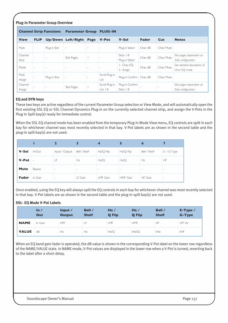
Plug-in Parameter Group Overview
EQ and DYN keysThese two keys are active regardless of the current Parameter Group selection or View Mode, and will automatically open thefirst existing SSL EQ or SSL Channel Dynamics Plug-in on the currently selected channel strip, and assign the V-Pots in thePlug In Spill bay(s) ready for immediate control.
When the SSL EQ channel mode has been enabled from the temporary Plug-In Mode View menu, EQ controls are spilt in eachbay for whichever channel was most recently selected in that bay. V-Pot labels are as shown in the second table and theplug-in spill bay(s) are not used.
Once enabled, using the EQ key will always spill the EQ controls in each bay for whichever channel was most recently selectedin that bay. V-Pot labels are as shown in the second table and the plug-in spill bay(s) are not used.
SSL- EQ Mode V-Pot Labels
When an EQ band gain fader is operated, the dB value is shown in the corresponding V-Pot label on the lower row regardlessof the NAME/VALUE state. In NAME mode, V-Pot values are displayed in the lower row when a V-Pot is turned, reverting backto the label after a short delay.
In / Out
Input /Output
Bell / Shelf
Hz / Q Flip
Hz / Q Flip
Bell / Shelf
E-Type /G-Type
NAME In Gain HPF LF LMF HMF HF LPF Hz
VALUE dB Hz Hz Hz/Q kHz/Q kHz kHF
1 2 3 4 5 6 7
V-Sel In/Out Input / Output Bell / Shelf Hz/Q Flip Hz/Q Flip Bell / Shelf E- / G-Type
V-Pot - LF Hz Hz/Q Hz/Q Hz HF
Mute Bypass - - - - - -
Fader In Gain - LF Gain LMF Gain HMF Gain HF Gain -
Channel Strip Functions Parameter Group PLUG-IN
View FLIP Up/Down Left/Right Page V-Pot V-Sel Fader Cut Notes
Multi - Plug-in Slot - - - Plug-in Select Chan dB Chan Mute
Channel
Strip- - Slot Pages 1 -
Slots 1-8
Plug-in SelectChan dB Chan Mute
Slot pages dependent on
Strip configuration
Mode - - - - -1- Chan EQ
2- AssignChan dB Chan Mute
See detailed description of
Chan EQ mode
Multi
Assign- Plug-in Slot - -
Scroll Plug-in
ListPlug-in Confirm Chan dB Chan Mute
Channel
Assign- - Slot Pages 1
Scroll Plug-in
List 1-8
Plug-in Confirm
Slots 1-8- -
Slot pages dependent on
Strip configuration
Soundscape Owner’s Manual Page 137

Channel/Track Selects V-Pots to Control of Channel I/O Routing, Solo and Fader/Mute Group assignment
Selecting CHANNEL will initially focus the V-Pots on mixer strip Input Source assignment in Multi View.
INPUT will be displayed on the lower display above the V-Pot.
The left/right cursor keys are used select the alternative V-Pot Control options, Output Routing, and the Fader and Solo groupassignment.
Changing Input and Output Routing operates as previously defined for Aux Sends. To change routing, press V-Sel and thenrotate the encoder until the correct input or output port is displayed, then operate the V-Sel switch again to confirm theroute. Routes will be displayed in the format ‘Type’ ‘Bus No. Device’ i.e. ‘Bus 1-2 U1’. The V-Pot is velocity sensitive to speedup scrolling through the sources or destinations. The V-Pot indicators will display.
While scrolling through the routes Soundscape will also display the list of possible Sources and Destinations and the currentposition in a list on-screen, which provides full names and a much better overview.
To change fader or solo group assignment, rotate the V-Pot until the required numbered group is displayed.
Fader and Solo Groups are only shown on screen, when Soundscape's Mixer is in WIDE View (X).
Switching to Channel View via a second operation of the CHANNEL switch displays the four channel setting function labelsunder V-Pots 1 – 4 in the bay containing the currently selected (SEL) channel. V-Pots 5-8 have no function and display ‘----‘ inthe label area.
Holding CHANNEL selects the temporary Channel Mode View, which uses V-Sel 1-4 to directly select Multi View with thelabelled function assigned to the V-Pots.
In either Channel Multi View or Channel Channel-Strip View, the modifier keys can be used to make global or selected channelroutes and groups.• OPTION + V-Sel Switch – All channels to the same source/destination/group• OPTION + ALT (CMND) + V-Sel Switch – All channels to incrementing source/destination/groups• SHIFT + OPTION + V-Sel Switch – Selected channels to the same source/destination/group• SHIFT + OPTION + ALT (CMND) V-Sel Switch – Selected channels to incrementing source/destination/groups
CHANNEL/TRACK Parameter Group Overview
Channel Strip Functions Parameter Group CHANNEL
View FLIP Up/Down Left/Right Page V-Pot V-Sel Fader Cut Notes
Multi - - Function Pages
1 Input SourceFlip Group /
Confirm RouteChan dB Chan Mute
2Output
Destination
Flip Group /
Confirm RouteChan dB Chan Mute
3 Fader Group Confirm Route Chan dB Chan Mute
4 Solo Group Confirm Route Chan dB Chan Mute
Channel
Strip- - - -
1- Input
2- Output
3- Fader Grp
4- Solo Grp
Flip Group /
Confirm RouteChan dB Chan Mute
Routing and Group control
for selected channel(s)
Mode - - - - -
1- Input
2- Output
3- Fader
4- Solo
Chan dB Chan MuteFast access to Multi View
options
Page 138 Soundscape Owner’s Manual

Modifier KeysSHIFT, CONTROL, OPTION, ALT These keys modify the actions of other functions keys as described in this overview and detailed in the associated functiontables above.
SHIFT, CONTROL and ALT parallel their equivalents on a standard QWERTY PC keyboard, OPTION is part of the MCU protocoland a valid key found on MAC keyboards. The modifier keys may be used on their own or in conjunction with other modifierkeys.
Mixer Channel NavigationTwo sets of keys, CHANNEL << // >> and BANK << // >>, control the relationship between the physical control surface channel stripsand the columns in Soundscape's Mixer.
Initially the surface strips are assigned to ascending channels starting from Column 1 in Soundscape's Mixer.
The CHANNEL keys shifts the surface focus by single channel increments in the indicated direction, and the BANK keys shiftsthe surface focus by a fixed channel amount (in multiples of eight) that can be user defined in the SSL Console ControlConfiguration Dialogue.
CHANNEL << +[Shift] Left justifies the mixer - Soundscape Mixer Column 1 is assigned to the first strip on the surface withascending channels assigned to the remaining strips.
CHANNEL > +[Shift] Right justifies the mixer - The last column in the Soundscape mixer is assigned to the rightmost stripon the surface with descending channels assigned to the remaining strips, from right to left.
BANK << +[Shift] Same as CHANNEL << +[Shift]
BANK > +[Shift] Assigns the banks containing the last channels in the Soundscape mixer to the controller, This isdependant on the size of the mixer, the channel bank size and the number of faders in the controlsurface.
NOTES: The active bays on the Console are shown in Soundscape's Mixer Column Number bar with a dark red background.The lowest indexed (or left most) Mixer column labelled “MASTER”, “Master” or “master” in Soundscape’s mixer is notincluded in CHANNEL or BANK operations and is always controlled from the dedicated Controller Master fader as wellas the normal console channel, if the Console supports this and the MASTER option in the SSL Console Control Settingis activated.
Soundscape Owner’s Manual Page 139

Channel Strip ControlsSEL Used to nominate the strip for various channel parameter operations detailed in the V-Pot Operation
description. Normally only a single strip can be selected and the SEL keys intercancel. HoweverMultiple strips can be selected in conjunction with the Modifier Keys. The current selected strip canbe deselected via a subsequent operation of the SEL key. Selected Mixer Strip is indicated on screen(mechanism to be determined) and via illuminating the SEL key tally.
SEL +[Shift] Selects all channels between the currently selected strip and the strip accessed via the SEL +[Shift]operation.
SEL +[Alt] Allows multiple non contiguous selection
SEL + OPT If a single strip selected, selects all strips. If multiple strips selected, cancels current strip selection.
REC(SEL) The editor audio track arming mode is enabled via the master REC ARM or REC key on the ControlSurface. Once enabled the SEL keys output the MCU key codes corresponding to the REC/RDYfunction. The Track arm command enables the Record function on the Editor channel assigned to theSoundscape mixer Strip.
REC +[Opt] Record enable all Tracks, or Global Cancel Record if tracks already enabled.
REC +[Opt]+[Shift] Record enable selected Tracks which have been previously selected via SEL +[Shift] or SEL +[Alt].
REC +[Alt] Record Enable Mixer Strip Automation Track
REC c+[Opt] Record Enable All Mixer Strip Automation Tracks, or Global Cancel Record if tracks already enabled.
REC +[Alt]+[Opt]+[Shift] Record enable Mixer Automation on Tracks which have been previously selected via SEL +[Shift] orSEL +[Alt].
SOLO Activates the Mixer Strip solo function.
SOLO +[Opt] Global solo on all tracks, or cancels active solo’s on all tracks.
SOLO +[Ctrl] Activates Solo on all Channels assigned to the same Solo Group
SOLO +[Opt]+[Shift] Activates Solo on all Channels which have been previously selected via SEL +[Shift] or SEL +[Alt].
MUTE Activates the Mixer Strip Output mute function.
MUTE +[Alt] Activates the Mixer Strip Input mute function.
MUTE +[Opt](/+[Alt]) Global Output mute on all tracks, or cancels active mutes on all tracks.
MUTE + CTRL (/+[Alt]) mutes All Channels assigned to the same Fader Group.
MUTE +[Opt]+[Shift] mutes all Channels which have been previously selected via SEL +[Shift] or SEL +[Alt].
Fader +[Ctrl] All Faders assigned to the same Fader Group follow the touched fader. The link is a relative dB linkand not just positional.
V-POT/V-SEL See V-Pot Operation for detailed description.
Page 140 Soundscape Owner’s Manual

DisplaysCounter: 10 digit (3+2+2+3) numeric display indicating current timeline position. Two readout options,
Timecode, -HH.MM.SS.FF-, or Bar(4)/Beats(2)/Sub Beats(3) -BB.BB.BB.SSS. Readout format istoggled with the SMPTE/BEATS key and two dedicated front panel tallies indicate SMPTE orBar/Beats.
SMPTE/BEATS Toggles Counter readout format.
DAW Solo or Solo Front panel Tally active if any mixer channel is in SOLO
Function Keys16 Functions Keys in conjunction with the modifier keys directly assign editing tools to the left and right mouse keys. Toconnect the Function keys to Soundscape Tools create a new Tool Page inside Soundscape with the order of the first 16Editing Tools reflecting the F1-16 keys. This Tool Page (ie. Page 5) can be selected in the SSL Console Control ConfigurationWindow with the MAP parameter (select 5 for Tool Page 5).
F-KEY(N) Assigns the loaded tool to the Left Mouse click
F-KEY(N) +[Ctrl] Assigns the loaded tool to the Right Mouse click
F-KEY(N) +[Alt] Assigns the loaded tool to the [Alt] Left Mouse click
F-KEY(N) +[Ctrl]+[Alt] Assigns the loaded tool to the [Alt] Right Mouse click
Automation ControlAUTO ENABLE Mixer Automation enable equivalent to the onscreen box or G keyboard shortcut
TOUCH Enables ‘Touch record’ in the Automation Setup menu. Default mode is Normal Record
TOUCH TO STOP Inter-cancels with TOUCH and enables ‘Touch record till stop’ in the Automation Setup menu. Defaultmode is Normal Record
CYCLE END Toggles the ‘Apply last recorded value from Part begin’ option in the Automation Setup menu
TAKE SNAPSHOT Equivalent to the on screen one shot ‘Snapshot Automation Record’ Function or F keyboard shortcut
General File/Edit CommandsSAVE Save Arrangement
SAVE+[Shift] Save Mix
UNDO Undo (as found in the Edit Menu)
UNDO+[Shift] Redo (as found in the Edit Menu)
The button tallies indicate if files are in an unsaved state or Undo/Redo's are available.
Soundscape Owner’s Manual Page 141
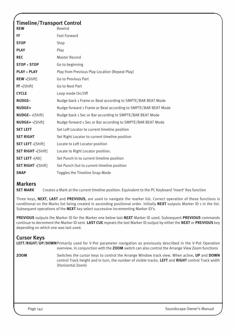
Timeline/Transport ControlREW Rewind
FF Fast Forward
STOP Stop
PLAY Play
REC Master Record
STOP + STOP Go to beginning
PLAY + PLAY Play from Previous Play Location (Repeat Play)
REW +[Shift] Go to Previous Part
FF +[Shift] Go to Next Part
CYCLE Loop mode On/Off
NUDGE– Nudge back 1 Frame or Beat according to SMPTE/BAR BEAT Mode
NUDGE+ Nudge forward 1 Frame or Beat according to SMPTE/BAR BEAT Mode
NUDGE– +[Shift] Nudge back 1 Sec or Bar according to SMPTE/BAR BEAT Mode
NUDGE+ +[Shift] Nudge forward 1 Sec or Bar according to SMPTE/BAR BEAT Mode
SET LEFT Set Left Locator to current timeline position
SET RIGHT Set Right Locator to current timeline position
SET LEFT +[Shift] Locate to Left Locator position
SET RIGHT +[Shift] Locate to Right Locator position.
SET LEFT +[Alt] Set Punch In to current timeline position
SET RIGHT +[Shift] Set Punch Out to current timeline position
SNAP Toggles the Timeline Snap Mode
MarkersSET MARK Creates a Mark at the current timeline position. Equivalent to the PC Keyboard ‘Insert’ Key function
Three keys, NEXT, LAST and PREVIOUS, are used to navigate the marker list. Correct operation of these functions isconditional on the Marks list being created in ascending positional order. Initially NEXT outputs Marker ID 1 in the list.Subsequent operations of the NEXT key select successive incrementing Marker ID’s.
PREVIOUS outputs the Marker ID for the Marker one below last NEXT Marker ID used. Subsequent PREVIOUS commandscontinue to decrement the Marker ID sent. LAST CUE repeats the last Marker ID output by either the NEXT or PREVIOUS keydepending on which one was last used.
Cursor KeysLEFT/RIGHT/UP/DOWNPrimarily used for V-Pot parameter navigation as previously described in the V-Pot Operation
overview. In conjunction with the ZOOM switch can also control the Arrange View Zoom functions
ZOOM Switches the cursor keys to control the Arrange Window track view. When active, UP and DOWNcontrol Track height and in turn, the number of visible tracks. LEFT and RIGHT control Track width(Horizontal Zoom)
Page 142 Soundscape Owner’s Manual

Jog WheelThe Jog Wheel is used to scroll the current timeline position, i.e. the current locator cursor. The Speed/Resolution is zoomlevel dependant, ie. faster when zoomed out.
SCRUB Selects the Audio Scrub Mode controlled by the Jog Wheel
Foot Switch ControlTwo momentary switch inputs to control transport functions.
INPUT 1 Toggles Transport play/stop; i.e. if Transport is stopped, first operation initiates play, and asubsequent operation stop
INPUT 2 Toggles Transport record, allowing remote punch in/out control
Soundscape Owner’s Manual Page 143
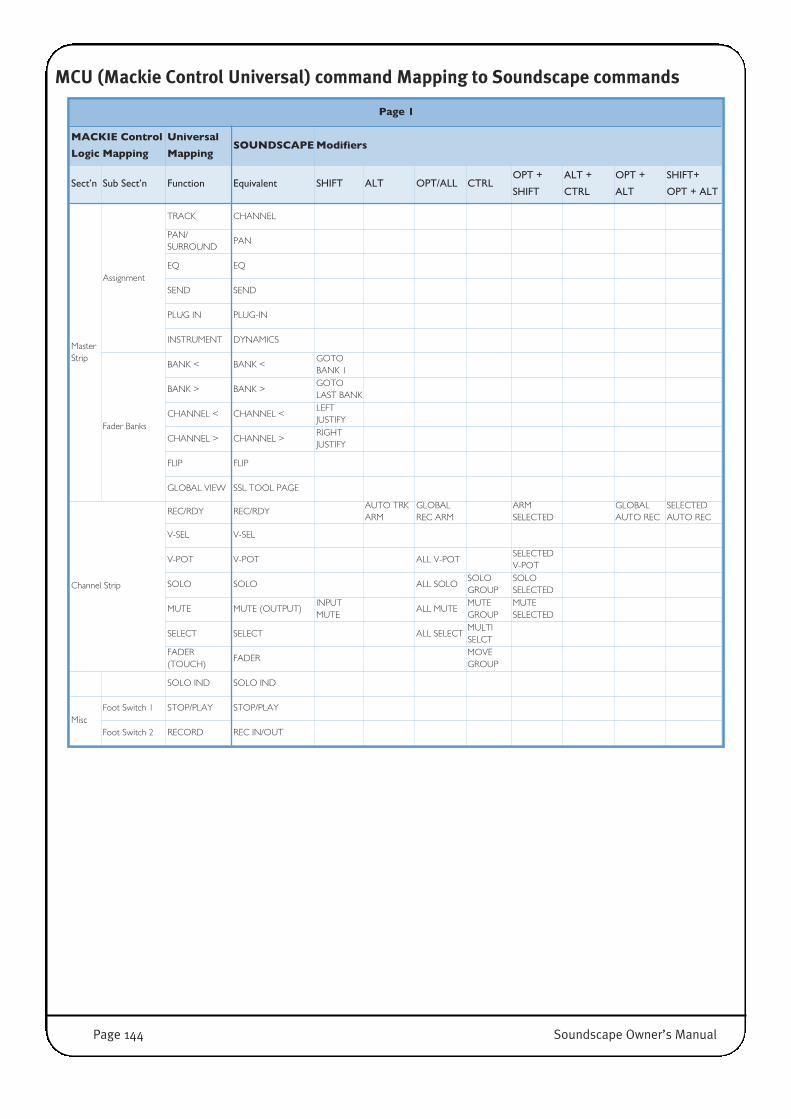
MCU (Mackie Control Universal) command Mapping to Soundscape commands
Page 1
MACKIE Control
Logic Mapping
Universal
MappingSOUNDSCAPEModifiers
Sect’n Sub Sect’n Function Equivalent SHIFT ALT OPT/ALL CTRLOPT +
SHIFT
ALT +
CTRL
OPT +
ALT
SHIFT+
OPT + ALT
MasterStrip
Assignment
TRACK CHANNEL
PAN/SURROUND
PAN
EQ EQ
SEND SEND
PLUG IN PLUG-IN
INSTRUMENT DYNAMICS
Fader Banks
BANK < BANK <GOTOBANK 1
BANK > BANK >GOTOLAST BANK
CHANNEL < CHANNEL <LEFTJUSTIFY
CHANNEL > CHANNEL >RIGHTJUSTIFY
FLIP FLIP
GLOBAL VIEW SSL TOOL PAGE
Channel Strip
REC/RDY REC/RDYAUTO TRKARM
GLOBALREC ARM
ARMSELECTED
GLOBALAUTO REC
SELECTEDAUTO REC
V-SEL V-SEL
V-POT V-POT ALL V-POTSELECTEDV-POT
SOLO SOLO ALL SOLOSOLOGROUP
SOLOSELECTED
MUTE MUTE (OUTPUT)INPUTMUTE
ALL MUTEMUTEGROUP
MUTESELECTED
SELECT SELECT ALL SELECTMULTISELCT
FADER(TOUCH)
FADERMOVEGROUP
SOLO IND SOLO IND
MiscFoot Switch 1 STOP/PLAY STOP/PLAY
Foot Switch 2 RECORD REC IN/OUT
Page 144 Soundscape Owner’s Manual
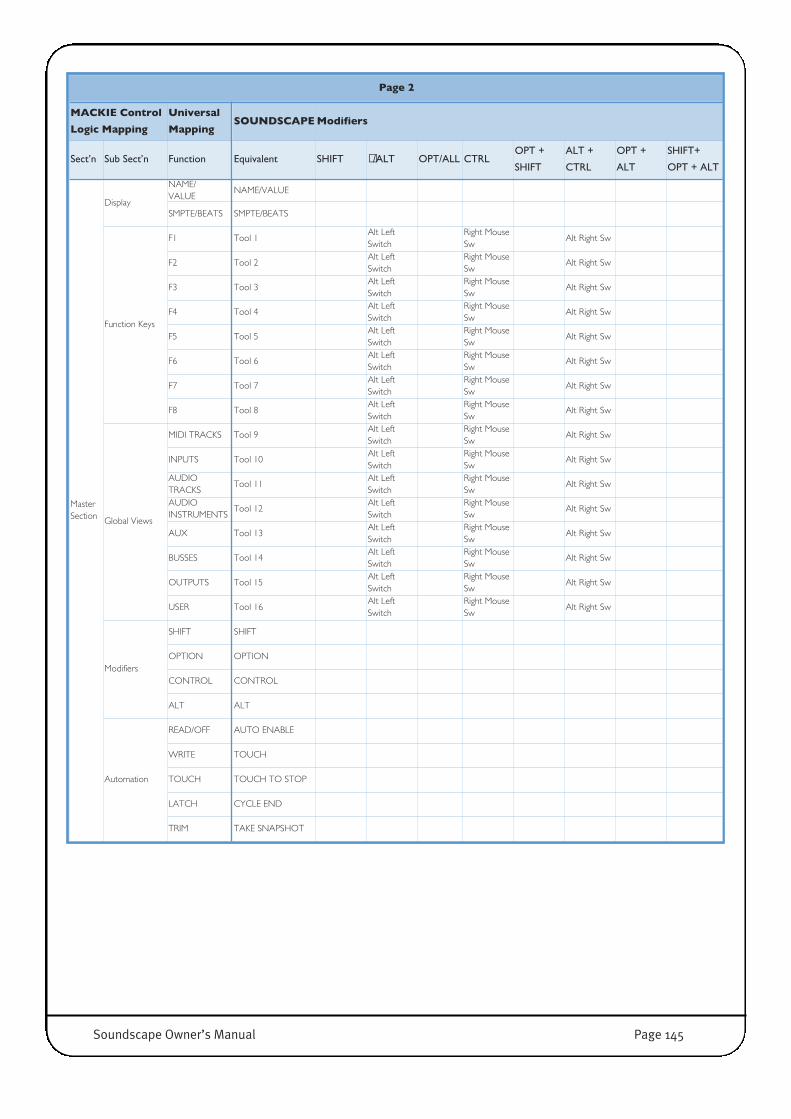
Page 2
MACKIE Control
Logic Mapping
Universal
MappingSOUNDSCAPEModifiers
Sect’n Sub Sect’n Function Equivalent SHIFT �/ALT OPT/ALL CTRLOPT +
SHIFT
ALT +
CTRL
OPT +
ALT
SHIFT+
OPT + ALT
MasterSection
Display
NAME/VALUE
NAME/VALUE
SMPTE/BEATS SMPTE/BEATS
Function Keys
F1 Tool 1Alt LeftSwitch
Right MouseSw
Alt Right Sw
F2 Tool 2Alt LeftSwitch
Right MouseSw
Alt Right Sw
F3 Tool 3Alt LeftSwitch
Right MouseSw
Alt Right Sw
F4 Tool 4Alt LeftSwitch
Right MouseSw
Alt Right Sw
F5 Tool 5Alt LeftSwitch
Right MouseSw
Alt Right Sw
F6 Tool 6Alt LeftSwitch
Right MouseSw
Alt Right Sw
F7 Tool 7Alt LeftSwitch
Right MouseSw
Alt Right Sw
F8 Tool 8Alt LeftSwitch
Right MouseSw
Alt Right Sw
Global Views
MIDI TRACKS Tool 9Alt LeftSwitch
Right MouseSw
Alt Right Sw
INPUTS Tool 10Alt LeftSwitch
Right MouseSw
Alt Right Sw
AUDIOTRACKS
Tool 11Alt LeftSwitch
Right MouseSw
Alt Right Sw
AUDIOINSTRUMENTS
Tool 12Alt LeftSwitch
Right MouseSw
Alt Right Sw
AUX Tool 13Alt LeftSwitch
Right MouseSw
Alt Right Sw
BUSSES Tool 14Alt LeftSwitch
Right MouseSw
Alt Right Sw
OUTPUTS Tool 15Alt LeftSwitch
Right MouseSw
Alt Right Sw
USER Tool 16Alt LeftSwitch
Right MouseSw
Alt Right Sw
Modifiers
SHIFT SHIFT
OPTION OPTION
CONTROL CONTROL
ALT ALT
Automation
READ/OFF AUTO ENABLE
WRITE TOUCH
TOUCH TOUCH TO STOP
LATCH CYCLE END
TRIM TAKE SNAPSHOT
Soundscape Owner’s Manual Page 145

Page 3
MACKIE Control
Logic Mapping
Universal
MappingSOUNDSCAPEModifiers
Sect’n Sub Sect’n Function Equivalent SHIFT �/ALT OPT/ALL CTRLOPT +
SHIFT
ALT +
CTRL
OPT +
ALT
SHIFT+
OPT + ALT
Master
Section
(cont)
Functions
SAVE SAVE SAVE MIX
UNDO UNDO REDO
GROUP SNAP
CANCEL LAST MARK
ENTER SET MARK
Locate Functions
MARKER SET LEFT GOTO L SET REC IN
NUDGE SET RIGHT GOTO RSET REC
OUT
CYCLE CYCLE
DROPNUDGE -
(FRM/BEAT)SEC/BAR
REPLACENUDGE +
(FRM/BEAT)SEC/BAR
CLICK PREVIOUS MARK
SOLO NEXT MARK
Transport Keys
REWIND REWGOTO
PREVIOUS PART
FF FFGOTO
NEXT PART
STOP STOP
PLAY PLAY
REC REC
Cursor Buttons
< <
> >
UP UP
DOWN DOWN
ZOOM ZOOM
Jog Wheel SCRUB SCRUB
Page 146 Soundscape Owner’s Manual

Legacy Console ManagerConsole Manager Properties WindowIf you have installed Console Manager (see Chapter 2) Click on Properties or double click the task bar icon to open the mainConsole Manager Properties Window
Console Manager allows external devicesto control the SSL Mixer software byreceiving data from these externaldevices and transmitting it to the MixerSoftware, using several possible ControlProtocols (HUI, MCU, JL Cooper etc.) thatcan be set up in the Console Interfacesection on the right hand side of thewindow.
The two sections on the left are used toselect the Hardware Ports (Serial ComPorts, Midi Interface, USB MIDI) thatbelong to the Hardware Controller orwhere the Controller is connected to(MIDI, RS422 etc.).
Setting Up Midi Controller DevicesThe MIDI Devices section has three buttons: Add, Remove, and Properties. The lattertwo appear greyed-out if no Midi device is selected or present.
Clicking the Add button opens the dialogue to create a new Device. Select anyavailable MIDI Input and Midi Output the device is connected to, and give thedevice a memorable name you can remember.
Clicking the Remove button when a device is selected opens a dialogue boxwhere the removal of that device must be confirmed. Click Yes to remove thedevice, click No to abort the operation.
Clicking the Properties button when a device is selected opens a dialogue boxwhich shows the properties of that device, as it was defined upon creation.
Right Clicking the entry of a MIDI device opens a menu with the same functions as thethree buttons described above.
Serial Port
Com Devices
MIDI Communication
Devices
Console Interfaces
for Hardware Controllers
Soundscape Owner’s Manual Page 147

Setting Up Serial Com Controller DevicesThe Serial Devices section has three buttons, Add, Remove, and Properties. The lattertwo appear greyed-out if no Serial Com device is selected or present.
Clicking the Add button opens the dialogue to create a new Device. Select anyavailable Serial Comport Device (RS232 or RS 422) the external device isconnected to, and give the device a memorable name you can remember.
Clicking the Remove button when a device is selected opens a dialogue boxwhere the removal of that device must be confirmed. Click Yes to remove thedevice, click No to abort the operation.
Clicking the Properties button when a device is selected opens a dialogue boxwhich shows the properties of that device, as it was defined upon creation.
Right Clicking the entry of a Serial Port device opens a menu with the same functions asthe three buttons described above.
Setting up Console InterfacesThe Console Interfaces section has five buttons, Add, Remove, and Properties, ChangeDevice and Information. The latter four appear greyed-out if no Console Interfacedevice is selected or present.
Clicking the Add button opens the dialogue to select the kind of device you haveconnected. The entries in the Interface list partly refer to industry standard
communication protocols and partly to dedicated Hardware devices. Some of thededicated Hardware devices, however, defined industry standard communicationProtocols. Selecting for example a MACKIE HUI interface also works with otherHardware, that supports the MACKIE HUI (HUI) protocol.
Select the appropriate Protocol/Device Interface and press OK.
Page 148 Soundscape Owner’s Manual

Clicking the Remove button when an Interface is selected opens a dialogue boxwhere the removal of that device must be confirmed. Click Yes to remove thedevice, click No to abort the operation.
When certain Console Interfaces such as the MIDIMixer Map Interface or Soundscape 9-Pin Slave
Interface are selected, clicking the Properties button opensa dialogue box which shows information about theinterface and allows editing of the setup.
This window also may include access to further windows,like the MIDI ‘Learn’ mode etc.
Clicking the Change Device button when a Console Interface is selected opensa dialogue box where any of the installed Serial Ports and MIDI devices can be
selected and assigned to the selected Console Interface:
NOTE: While any controller device can be selected from the list, the selectedConsole Interface will only function correctly with a compatible device.
Clicking the Information button opens aninformation window about the selected Console
Interface.
Right-clicking on a Console Interface opens a menu with five entries that match thefunctions of the five buttons just discussed.
Soundscape Owner’s Manual Page 149

Activating a Console InterfaceWhen the Console Interface is created and assigned to an appropriate CommunicationDevice (Serial or MIDI) and the Hardware Controller is connected to the selectedcommunication device, you can activate the Console Interface by checking the tick boxbelonging to the Interface entry. (Penny + Giles MM16 Interface in the screen shot onthe right).
NOTE: While several Console Interfaces can be used simultaneously to control the same Mixer, certain configurationscreate conflicts and different Hardware Controllers start to ‘fight’ for the right Fader Position.
Saving a Console Manager configuration Activating the option Connect to Console Manager in the menu: Settings / Preferences / Mixer initiates the basiccommunication between Soundscape and the Console Manager Module.
Performing a Save Settings (from the Settings menu) while Console Manager is running and connected makes the connectionpermanent, and Console Manager will be launched automatically the next time the SSL Mixer is started.
Console Manager’s settings are saved automatically whenever you change any setting and will automatically run the sameconfiguration on next start up. This includes the selection of Communication devices, created Console Interfaces, devicesselection and Activation Status of the Console Interfaces.
NOTE: When Console Manager starts up (together with launching the SSL Mixer) it scans the computer for availableCommunication Devices. If you for example have a USB Hardware Controller, that is still switched off, Console Managercan not initialise the MIDI Port(s). In order to remedy the situation you should re-launch the Mixer software after youhave switched on the Controller.
Closing Console ManagerConsole Manager will automatically close at the same time as the Soundscapesoftware, provided that no Console Manager windows and/or dialogue box is stillopened, in which case the following dialogue box will appear.
The same dialogue box will appear, when you disable Connect to Console Manager inthe Mixer Software, and Console Manager windows are still open.
Page 150 Soundscape Owner’s Manual
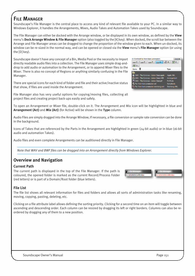
FILE MANAGERSoundscape’s File Manager is the central place to access any kind of relevant file available to your PC. In a similar way toWindows Explorer, it handles the Arrangements, Mixes, Audio Takes and Automation Takes used by Soundscape.
The File Manager can either be docked with the Arrange window, or be displayed in its own window, as defined by the Viewmenu’s Dock Arrange Window & File Manager option (also toggled by the [K] key). When docked, the scroll bar between theArrange and File Manager areas can be dragged to change the proportion of the window given to each. When un-docked, itswindow can be re-sized in the normal way, and can be opened or closed via the View menu’s File Manager option (or usingthe [D] key).
Soundscape doesn't have any concept of a Bin, Media Pool or the necessity to Importdirectly readable audio files into a collection. The File Manager uses simple drag-and-drop to add audio or automation to the Arrangement, or to append Mixer files to theMixer. There is also no concept of Regions or anything similarly confusing in the FileManager.
There are special icons for each kind of folder and file and their active/inactive statusthat show, if files are used inside the Arrangement.
File Manager also has very useful options for copying/moving files, collecting allproject files and creating project back-ups easily and safely.
To open an Arrangement or Mixer file, double-click on it. The Arrangement and Mix icon will be highlighted in blue andArrangement (Act) and Mix (Act) (for Active) will be shown in the Type column.
Audio Files are simply dragged into the Arrange Window; If necessary, a file conversion or sample rate conversion can be donein the background.
Icons of Takes that are referenced by the Parts in the Arrangement are highlighted in green (24-bit audio) or in blue (16-bitaudio and automation Takes).
Audio files and even complete Arrangements can be auditioned directly in File Manager.
Note that WAV and BWF files can be dragged into an Arrangement directly from Windows Explorer.
Overview and NavigationCurrent PathThe current path is displayed in the top of the File Manager. If the path iscoloured, the opened folder is marked as the current Record/Process Folder(red letters) or is part of a Domain/Root folder (blue letters).
File ListThe file list shows all relevant information for files and folders and allows all sorts of administration tasks like renaming,moving, copying, pasting, deleting, etc.
Clicking on a file attribute label allows defining the sorting priority. Clicking for a second time on an item will toggle betweenascending and descending order. Each column can be resized by dragging its left or right borders. Columns can also be re-ordered by dragging any of them to a new position.
Soundscape Owner’s Manual Page 151
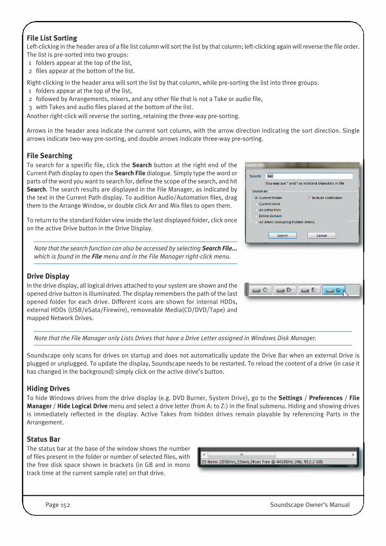
File List SortingLeft-clicking in the header area of a file list column will sort the list by that column; left-clicking again will reverse the file order.The list is pre-sorted into two groups:1 folders appear at the top of the list,2 files appear at the bottom of the list.
Right-clicking in the header area will sort the list by that column, while pre-sorting the list into three groups:1 folders appear at the top of the list,2 followed by Arrangements, mixers, and any other file that is not a Take or audio file,3 with Takes and audio files placed at the bottom of the list.
Another right-click will reverse the sorting, retaining the three-way pre-sorting.
Arrows in the header area indicate the current sort column, with the arrow direction indicating the sort direction. Singlearrows indicate two-way pre-sorting, and double arrows indicate three-way pre-sorting.
File SearchingTo search for a specific file, click the Search button at the right end of theCurrent Path display to open the Search File dialogue. Simply type the word orparts of the word you want to search for, define the scope of the search, and hitSearch. The search results are displayed in the File Manager, as indicated bythe text in the Current Path display. To audition Audio/Automation files, dragthem to the Arrange Window, or double click Arr and Mix files to open them.
To return to the standard folder view inside the last displayed folder, click onceon the active Drive button in the Drive Display.
Note that the search function can also be accessed by selecting Search File...which is found in the Filemenu and in the File Manager right-click menu.
Drive DisplayIn the drive display, all logical drives attached to your system are shown and theopened drive button is illuminated. The display remembers the path of the lastopened folder for each drive. Different icons are shown for internal HDDs,external HDDs (USB/eSata/Firewire), removeable Media(CD/DVD/Tape) andmapped Network Drives.
Note that the File Manager only Lists Drives that have a Drive Letter assigned in Windows Disk Manager.
Soundscape only scans for drives on startup and does not automatically update the Drive Bar when an external Drive isplugged or unplugged. To update the display, Soundscape needs to be restarted. To reload the content of a drive (in case ithas changed in the background) simply click on the active drive’s button.
Hiding DrivesTo hide Windows drives from the drive display (e.g. DVD Burner, System Drive), go to the Settings / Preferences / FileManager / Hide Logical Drive menu and select a drive letter (from A: to Z:) in the final submenu. Hiding and showing drivesis immediately reflected in the display. Active Takes from hidden drives remain playable by referencing Parts in theArrangement.
Status Bar�The status bar at the base of the window shows the numberof files present in the folder or number of selected files, withthe free disk space shown in brackets (in GB and in monotrack time at the current sample rate) on that drive.
Page 152 Soundscape Owner’s Manual
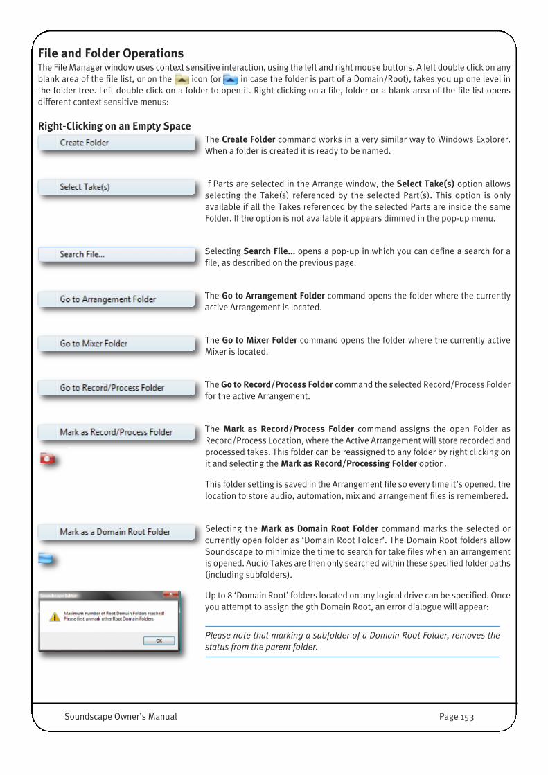
File and Folder OperationsThe File Manager window uses context sensitive interaction, using the left and right mouse buttons. A left double click on anyblank area of the file list, or on the icon (or in case the folder is part of a Domain/Root), takes you up one level inthe folder tree. Left double click on a folder to open it. Right clicking on a file, folder or a blank area of the file list opensdifferent context sensitive menus:
Right-Clicking on an Empty SpaceThe Create Folder command works in a very similar way to Windows Explorer.When a folder is created it is ready to be named.
If Parts are selected in the Arrange window, the Select Take(s) option allowsselecting the Take(s) referenced by the selected Part(s). This option is onlyavailable if all the Takes referenced by the selected Parts are inside the sameFolder. If the option is not available it appears dimmed in the pop-up menu.
Selecting Search File... opens a pop-up in which you can define a search for afile, as described on the previous page.
The Go to Arrangement Folder command opens the folder where the currentlyactive Arrangement is located.
The Go to Mixer Folder command opens the folder where the currently activeMixer is located.
The Go to Record/Process Folder command the selected Record/Process Folderfor the active Arrangement.
The Mark as Record/Process Folder command assigns the open Folder asRecord/Process Location, where the Active Arrangement will store recorded andprocessed takes. This folder can be reassigned to any folder by right clicking onit and selecting the Mark as Record/Processing Folder option.
This folder setting is saved in the Arrangement file so every time it’s opened, thelocation to store audio, automation, mix and arrangement files is remembered.
Selecting the Mark as Domain Root Folder command marks the selected orcurrently open folder as ‘Domain Root Folder’. The Domain Root folders allowSoundscape to minimize the time to search for take files when an arrangementis opened. Audio Takes are then only searched within these specified folder paths(including subfolders).
Up to 8 ‘Domain Root’ folders located on any logical drive can be specified. Onceyou attempt to assign the 9th Domain Root, an error dialogue will appear:
Please note that marking a subfolder of a Domain Root Folder, removes thestatus from the parent folder.
Soundscape Owner’s Manual Page 153
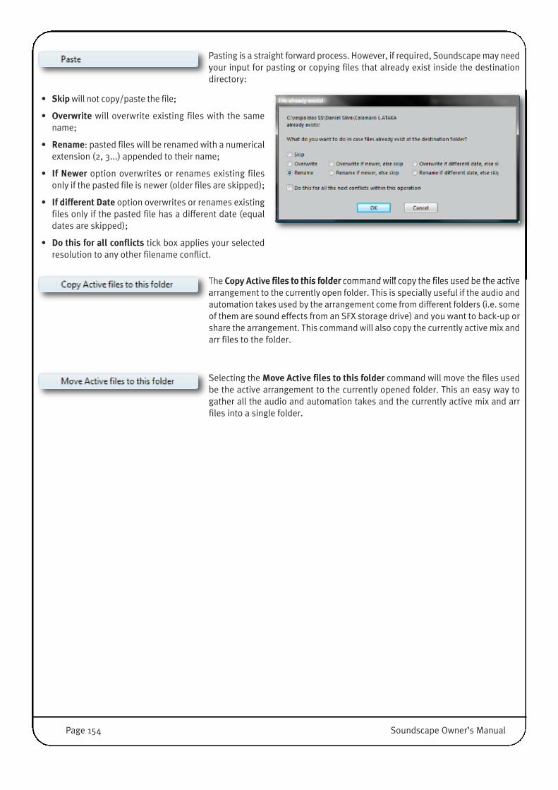
Pasting is a straight forward process. However, if required, Soundscape may needyour input for pasting or copying files that already exist inside the destinationdirectory:
• Skip will not copy/paste the file;
• Overwrite will overwrite existing files with the samename;
• Rename: pasted files will be renamed with a numericalextension (2, 3...) appended to their name;
• If Newer option overwrites or renames existing filesonly if the pasted file is newer (older files are skipped);
• If different Date option overwrites or renames existingfiles only if the pasted file has a different date (equaldates are skipped);
• Do this for all conflicts tick box applies your selectedresolution to any other filename conflict.
The Copy Active files to this folder command will copy the files used be the activearrangement to the currently open folder. This is specially useful if the audio andautomation takes used by the arrangement come from different folders (i.e. someof them are sound effects from an SFX storage drive) and you want to back-up orshare the arrangement. This command will also copy the currently active mix andarr files to the folder.
Selecting the Move Active files to this folder command will move the files usedbe the active arrangement to the currently opened folder. This an easy way togather all the audio and automation takes and the currently active mix and arrfiles into a single folder.
Page 154 Soundscape Owner’s Manual

Right clicking on a folderRight clicking on a folder opens a different context sensitive menu.
Rename, Cut and Copy work in the same way as in Windows Explorer. The Mark as Domain Root Folder function is alsopresent in this menu.
Right click and select Delete on anyFolder in the File Manager window to
delete it. If there are Parts in the Arrange window that reference Take(s) inside thisfolder, a dialogue box will be displayed.
Click on Yes only if you want to continue with deleting the Take(s).
If any Part(s) in the current Arrangement reference any Take(s), a further dialoguebox appears that warns you that this (these) Part(s) will be deleted.
It is also possible to delete Folders or any other files from the File Manager windowby highlighting the relevant file and then using the [Delete] key.
NOTE: Be very careful when deleting Files. You can undo the delete and there are up to 99 levels of undo. However, ifyou perform several operations after deleting Files, it is not certain that you will be able to recover them. It depends ifthey have been physically overwritten on the disk. Files deleted in Soundscape File Manager are not put into WindowsRecycle Bin.
By selecting Delete empty Folder trees only, all empty folders and subfolderswithin the currently selected folder are deleted.
Right clicking on a Take File�Right clicking on an audio Take (ATAK, WAV or BWF) file opens another menu.
Rename, Cut and Copy behave in the same way as you would expect in Windows Explorer.
Delete, Delete empty Folders trees only have been explained above.
With the Replace Take(s) command, you can replace the Take references of oneor more selected Parts (in the Arrange Window) with the selected Take (in theFile Manager).
This option is only available if the selected Take is at least as long as the longest selected Part and is of the same type as allthe selected Parts (Audio or Automation).
Please note that the Part’s Start in Take offset parameter (as shown in the Part Info window) is maintained, and the selectedTake must also be long enough to allow for that offset.
If Replace Take(s) is dimmed/greyed out, the original Part is longer than selected new Take.
The selected Part(s) will also be renamed using the new Take's name if the Replace Part name(s) as well when replacingTake(s) option is selected under Settings / Preferences / Arrangement menu.
Soundscape Owner’s Manual Page 155

Conversion Options:Depending on the format of the file you have selected, various conversion optionsmay be included in the menu:
• Convert multi-channel WAV/BWF files into mono BWF Audio Takes will convert multi channel (stereo or more) WAV orBWF files into separate mono BWF files and add them to the current folder. Since Soundscape only works with multiplemono files, this process is automatically done in the background when multi-channel WAV/BWF files are dragged into theArrangement Window.
• Clicking on Convert mono or multi-channel WAV/BWF files into mono ATAK Audio Takes will convert mono or multichannel (stereo or more) WAV/BWF files into single/multiple mono Soundscape ATAK files which can directly used insidethe Arrange Window.
• Selecting Convert mono Audio Takes into multi-channel BWF files will convert mono audio take file(s) (ATAK or BWF) intomultichannel BWF files. This is useful for mixdowns or stems you want to use in CD Burning or DVD Authoring applications.
• Selecting Convert mono ATAK Audio Takes into mono BWF Audio Takes will convert proprietary SSL Soundscape ATAKfiles (always mono) into BWF files, for use in other Audio Applications.
• Convert to mono BWF Audio Takes will convert a mono file into BWF format.
• Convert to mono ATAK Audio Takes will convert a mono file into ATAK format.
Depending on the formatof the selected audio file,
a Properties entry may be displayed in the menu. This will open adialogue box like the one shown to the right. You can Name the Take,add a Comment, view file details, and set the Sample Rate, FrameRate and Start time.
Page 156 Soundscape Owner’s Manual

Right clicking on an Arrangement FileRight clicking on an Arrangement file opens another menu.
Rename, Cut and Copy behave in the same way as you would expect in Windows Explorer.
Delete, Delete empty Folders trees only have been explained above.
Pro-ConvertThe Pro-Convert options allow you to convert the selected Arrangement into athird party format, such as Protools or Logic. The Pro-Convert to option providesa quick way to do this, whereas Pro-Convert opens a conversion dialogue inwhich advanced settings can be adjusted.
Pro-Convert procedures are covered in detail in the ‘Project Conversion’ section of this chapter.
Right clicking on an Automation File�Right clicking on an Automation file opens another menu.
Rename, Cut and Copy behave in the same way as you would expect in Windows Explorer.
Delete, Delete empty Folders trees only and Replace Take(s) have been explained above.
The Properties option opens a dialogue box which includes ‘Knobs’ and ‘Events’information.
Auditioning Files and ArrangementsAuditioning (Preview, Playback) an Audio Take inside the File Manager is done as follows:• Right-click on the Take• Hold the Right mouse button• Move the mouse pointer a little to the left or right
The mouse pointer will turn into the Solo tool (Ear Icon). The audio will always be played from the beginning of the Take,including any initial silence.
Takes are played back through the same track(s) as muted Parts. By default this is Track 1, but this can be changed in theSettings / Muted Parts/Takes Solo Output / Audio menu.
Full Arrangements can be auditioned in the same way, but they are played back through the currently active Mixer so theymay not sound as expected. In particular, the active Mixer should have track inserts for all the tracks used by the Arrangement.
This is an extremely powerful function and loads a whole project in the background. Depending on the complexity it thereforemay take a second until Playback of the Arrangement starts. Leading silence inside the Arrangements is naturally also ‘played’.
Soundscape Owner’s Manual Page 157
Opening and Dragging Files into the Arrange WindowOpening Folders, Arrangements and Mixer FilesIn the usual Windows manner, double clicking on folders opens them. Arrangements and Mixer files can also be opened bydouble-clicking on them in the File Manager.
Dragging Takes and Arrangements into the Arrange windowA Take (Audio or Automation) can be dragged (click+hold mouse) from the File Manager and dropped (release mouse) at anytime position on any virtual track inside the Arrange window as a Part. WAV and BWF files can also be dragged directly fromWindows Explorer into the Arrangement. Dragging/dropping will take the current Snap setting into account (if active).
Takes can only be dragged and dropped one by one, even if multiple Takes are selected. Stereo and multichannel audioTakes are automatically dragged together and become Stereo/Multi Linked Parts inside the Arrangement. This requires thatTakes have the same length and the same name (appended with L / R or the Multi-Ch extension).
If you drag a Take from the File Manager into the Arrange window and drop it on a virtual track that has an output assignmentin the Record Track Column, then the Part will automatically be assigned to that Track and be colour-coded accordingly.
WARNING: If the Sample Rate of a dragged Take is different to the Sample Rate of the Arrangement, it may be convertedautomatically depending on the setting of the Auto Sample Rate Convert Process Audio Takes when dragged intoArrangement option under Settings / Preferences.
The Sample Rate Convert Process tool performs the conversion, and as for all audio processing tools the source audio Take(s)may be deleted automatically, depending on the setting of the audio processing tools behaviour (Settings / Preferences)
Arrangements can be dragged into the Arrange window in the same way as Takes. This will not replace the active arrangement,but add the Parts / append an arrangement. Part and Track assignments will also be adopted automatically when recordTracks are defined on destination virtual Tracks.
Dragging Takes or Arrangements to original Time Code using the [Ctrl] KeyA Take file can be dragged from the File Manager and dropped (as a Part) at the time position where it was originally recorded(i.e., the start time shown in the File Manager, Time Stamp inside a BWF File), by holding down the [Ctrl] key whiledragging/dropping.
Dragging an Arrangement to the original Time Position works in the same way.
Important:• If the original time position is outside the currently displayed time range, you will not see the dropped audio. • If the error message Parts cannot be dropped out of range appears, the original time position could be earlier than the
start of this Arrangement (due to SMPTE Offset) or is outside the maximum time range that is possible for one Arrangement(approximately 13.5h)
Dragging Takes or Arrangements to a Locator using the [Alt] KeyTo drag a Take or Arrangement from the File Manager to a Locator position in the Arrange window, press the [Alt] key whiledragging/dropping and the beginning or end of the Part or any Part inside the dragged Arrangement will be positioned at thenearest Locator automatically.
Page 158 Soundscape Owner’s Manual

PROJECT CONVERSIONIntroductionSSL Soundscape 6.2 can read and write several third party project formats directly using the File Menu or context sensitiveright click menu's in the File Manager Window, thanks to the build in SSL Pro-Convert technology.
Reading and Writing 3rd Party Audio Projects The Pro-Convert Engine can process audio related timeline information from any supported source project file and translatethis to Soundscape V6 Arrangement. The supported information contains:
Edits, Regions, standard Fade Shapes, Track Names, Media Files (Audio+ single Video Track), Markers/PQ Data, Volume andPan Automation, Region/Clip Gain and Cross-fades.
When saving an Arrangement as a 3rd Party project the same information is exported to the destination format.
What Pro-Convert doesn't doMidi, Instruments, REX and Apple Loops, Mixers and Plug-Ins, custom Clip Gain Envelopes, Pitch and Time-corrected Tracks,anything that can't simply be translated or isn't present in all supported DAW's, is unsupported information Pro-Convertcannot process.
All modern DAW's, however, offer a "Freeze, Consolidate, Bounce to Disk, Commit to Disk or similar function" that can rendernot supported events into standard audio tracks, before the projects are opened with Soundscape.
Audio File conversionPro-Convert can also translate the audio files for you. In various project conversions this is mandatory, when source anddestination DAW's are not be able to use the same audio file types, the same or multiple bit depths or share the same strategyon how to create stereo tracks (interleaved Stereo vs. two Mono files).
Conversion is never going to be perfect, In order to get the most accurate (=100%) representation of a project, SoundscapeALWAYS needs to store a project in it’s own Arrangement Format first before export to another format.
On Import, ANY 3rd party project will first be saved as a Soundscape Arrangement, which is then opened.
File Format Description Ext. Supported Bit Depths
Supportedon
Notes
Wave The major audio format on
Windows OS
*.wav 8, 16, 24, 32 linear,
32 float
Import and
Export
Bit Depth support is Host dependant
Broadcast Wave Wave Format including
Metadata and Time Stamps
*.wav 8, 16, 24, 32 linear,
32 float
Import and
Export
Bit Depth support is Host dependant
Audio Interchange
File Format
The major audio format on
Mac OS
*.aif 8, 16, 24, 32 linear Import and
Export
Bit Depth support is Host dependant
Audio Interchange
Format (comp.)
Adds Compression Support
to AIFF files
*.aic 8, 16, 24, 32 linear,
32 float
Import and
Export
Only uncompressed files are supported!!!
SSL Soundscape
Take File Format
Soundscape Audio File-
format on Editor v4.2 or later
*.atak 16, 24 Import and
Export
Only supported when residing on Windows
Drives, SDisks are not supported
Soundscape Owner’s Manual Page 159

Successful Imports and Exports......largely depend on audio files being where they should be, Projects being Sample and not Tick based and Destination foldersbeing accessible.
Also the Project Files need to be written in a „format version“, that is known to Pro-Convert.
If you want to import a project into Soundscape, please also do remember to load or create a Mixer.
NOTE: Tick based ppq resolutions differ between Sequencers, in order to maintain the project timing during conversionPro-Convert does NOT support Audio projects with Tick based Times.
InstallationPro-Convert installation is described in the installation section towards the start of the manual.
NOTE: All described Pro-Convert menu entries are only available if Pro-Convert for Soundscape has been installed, anda valid Soundscape password has been entered in Soundscape’s Options dialogue.
ProjectFormat
Project File Versions Ext. Description Notes
PPrroo--TToooollss 77..xx ttoo 99..xx SSeessssiioonn FFiillee
Import V 7.x to Version 9.x
Export V 7.x are created
*.ptf AVID’s session format for Pro Tools
Verson 7 to 9.x. Pro-Convert always
exports sessions in the 7.x format.
SDII audio Files are NOT
supported.
SStteeiinnbbeerrgg 33..xx ttoo 55..xx XXMMLL TTrraacckk aarrcchhiivvee
Import V 3.x to Version 5.x
Export V 3.x are created
*.xml XML format that can be used with
Steinberg Nuendo 3.x and later and
Cubase SX3.x and later.
-
SSaammpplliittuuddee EEDDLL
Import V 10.x
Export V 10.x
(also supports Reaper and Sequioa)
*.edl .edl format generated by Magix
Samplitude/Sequioa or Cockos
Reaper.
AAppppllee FFiinnaall CCuutt VV11--22..xx XXMMLL
Import V 1 to Version 2.x
Export V 2.x are created
*.xml XML format that is used with Final
Cut Pro 4 and later, Logic 8 and later
and Soundtrack Pro 2 or later.
Logic 8 and 9 do not export
any edits, but bounce all
Tracks as single files.
SSSSLL SSoouunnddssccaappee VV66 AArrrraannggee
Import V 6.2 or later
Export V 6.2 or later are created
*.arr Arrange file format; Audio Project
Format used by SSL’s Soundscape™
V6.2 or later.
SSSSLL SSoouunnddssccaappee EEddiittoorr AArrrraannggee
Import V 4.x to Version 5.5
Export V 5.5 are created
*.arr Arrange file format; Audio Project
Format used by Solid-State-Logic's
Soundscape™ Editor v4.x or later.
Files on SDisks are not
supported
Page 160 Soundscape Owner’s Manual

Opening Third-Party ProjectsTo open third-party projects, select File / Open Arr..., browse to the desired folder, and change the visibility option (in thebottom right-hand corner of the window) to the file type you want to open (or All Files).
As an alternative you can simply double click on any recognised third-party project inside the File Manager window.
Pro-Convert for Soundscape translates audio track related information in the third-party project file to a SoundscapeArrangement, using default conversion settings, and if required, also convert the audio files. At the end of the process aSoundscape Arrange File is written to the same folder and automatically opened.
A progress and logging window will appear during the conversion, similar to that shown below.
Quick-Saving in Third-Party Project FormatsTo save a session in a third-party projectformat, select File / Save ARR and Pro-Convertto... and browse to the desired folder. Definethe name and file type, and press Save. Thiswill first save the currently active Arrangementand then create a new file in the selected third-party project format with standard conversionsettings in the same folder.
Alternatively, if the file you wish to convert isnot open, right-click on any supported Projectin the File Manager, select Pro-Convert to fromthe menu which appears, and select the formatin the subsequent sub-menu. This will createa new third-party project file in the samefolder.
With either method, a progress and logging window will be displayed during the conversion, similar to that shown above.
NOTE: For best results, older Soundscape Arrangements (Arr. Created with V6.1 or earlier) should be saved with Version6.2 or later as a copy or with a new name to guarantee, that the Arr. Format has the latest file version that Pro-Convertfor Soundscape understands.
Soundscape Owner’s Manual Page 161
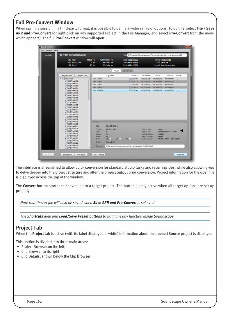
Full Pro-Convert WindowWhen saving a session in a third-party format, it is possible to define a wider range of options. To do this, select File / SaveARR and Pro-Convert (or right-click on any supported Project in the File Manager, and select Pro-Convert from the menuwhich appears). The full Pro-Convert window will open:
The interface is streamlined to allow quick conversion for standard studio tasks and recurring jobs, while also allowing youto delve deeper into the project structure and alter the project output prior conversion. Project information for the open fileis displayed across the top of the window.
The Convert button starts the conversion to a target project. The button is only active when all target options are set upproperly.
Note that the Arr file will also be saved when Save ARR and Pro-Convert is selected.
The Shortcuts area and Load/Save Preset buttons to not have any function inside Soundscape
Project TabWhen the Project tab is active (with its label displayed in white) information about the opened Source project is displayed.
This section is divided into three main areas:• Project Browser on the left;• Clip Browser to its right;• Clip Details, shown below the Clip Browser.
Page 162 Soundscape Owner’s Manual

1. Project BrowserThe two buttons at the top of the project Browser define whether the rest of the window displays all the audio tracks (ProjectTracks selected) or all the source files (Project Files selected) used inside the project.
When in Project Tracks View, you can exclude full tracks from the conversion by un-ticking their check box. This can be usefulto create different target projects excluding Dialogues or Mix downs or to create different language versions of a project.
2. Clip BrowserThe Clip Browser shows a list of all clips (or edits) on a selected Track (Project Tracks active) or for a selected source file(Project Files active). The Clip (Part) Name, Source (Take) In and Out times, Edit (Timeline Position) In and Out times, andTrack No (numbers) are displayed.
Source I/O times refer to the sector that is used from the original audio source; Edit I/O times refer to the start and end ofthe Clip inside the timeline.
Clicking on any of the Clips reveals more information in the Details area below the Clip Browser:
3. Clip Details Clips in Pro-Convert are the smallest piece of edit information inside the timeline. The following details are extracted from thesource project: Clip Name, Duration; Gain (Level); Time Locked status; Mute status; Automation present for Clip Gain, Volumeor Pan; Fade In/Out Type and Time (can also relate to Cross-Fades), Audio Format, Track number in the project, and thereferenced audio Source path.
Conversion TabAll settings for the conversion to the Target Project are altered inside the Conversion tab.
Soundscape Owner’s Manual Page 163

The Conversion setup is divided into six logical sections, explained over the following pages:
1. Project Conversion: Here you can select the target Format and add a comment for the conversion
2. Project Location:Here you can select the disk and sub folder to which you want to save the new project and name the new file, using standardwindows file navigation procedures. If you would like a project folder to be created for the new format, select the Createproject folder check box.
3. Global Project Settings:This section shows format-specific settings.
The Tracks options allow you to ignore empty tracks, ignore muted Tracks and clips, and ignore alternative takes/sub-tracks.
If is present in the source project and possible in the target format, Markers and PQ-Data can be selected for conversion inthe Misc area.
If the Source Project contains one or more Video references, the Video area will be displayed on the right. One Video can beincluded into the conversion process.
IMPORTANT: Pro-Convert does not convert or trans-code at all. It simply copies the selected original video file to thenew target destination project folder (if this option is selected) and adds a reference inside the target project file (ifpossible).
If a video-file (or multiple video files) is present, the Video file browser can re-map the Video file and, if the source projectcontains more than one Video track, select the video track that should be included in the conversion.
4. Timecode and OffsetThis section displays the projects timecode settings and project Offset. No settings in this section can be changed.
5. Fades and AutomationThis section controls the handling of Fades and Cross-Fades, as well as Clip Gain, Volume and Pan automation.
Fades: With Translate Fades checked, Pro-Convert translates all fades and crossfades to the target project usingthe best possible match for standard Fade Curves between Source and Target. Any sort of custom fadeshape is not supported and should be removed from the source project, prior to using Pro-Convert.
With Ignore Fades selected, all Fades will be removed from the project during conversion.
Automation: Depending on source and target format capabilities, the following options may be available:
If Translate Vol Curves is checked, volume curves and volume automation will be translated. In most cases,these curves control the DAW's volume faders in the mixer. To adjust volume automation data which goesbeyond the maximum possible value in the target format, all existing volume automation data can bereduced by selecting the Rescale box (which appears when Translate Vol Curves is active) and moving theslider which then appears to its right. The rescale amount is shown in dB.
If the source format contains pan automation, activating the Translate Pan Curves option allows them tobe translated to the target project. In most cases, these curves control the DAW's pan pot in the mixer.
The Translate Clip gain option allows to use Clip Gain Information from the source project and whendestination projects support this feature, create Clip Gain in the target project. To adjust gain data whichgoes beyond the maximum possible value in the target format, all existing gain data can be reduced byselecting the Rescale box (which appears when Translate Clip gain is active) and moving the slider whichthen appears to its right. The rescale amount is shown in dB.
Page 164 Soundscape Owner’s Manual
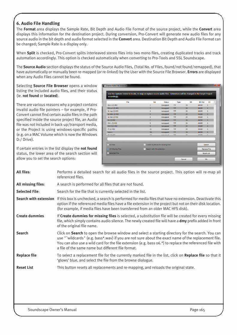
6. Audio File HandlingThe Format area displays the Sample Rate, Bit Depth and Audio File Format of the source project, while the Convert areadisplays this information for the destination project. During conversion, Pro-Convert will generate new audio files for anysource audio in the bit depth and audio format selected in the Convert area. Destination Bit Depth and Audio File Format canbe changed; Sample Rate is a display only.
When Split is checked, Pro-Convert splits interleaved stereo files into two mono files, creating duplicated tracks and trackautomation accordingly. This option is checked automatically when converting to Pro-Tools and SSL Soundscape.
The Source Audio section displays the status of the Source Audio Files, (Total No. of Files, found/not found/remapped), thathave automatically or manually been re-mapped (or re-linked) by the User with the Source File Browser. Errors are displayedwhen any Audio Files cannot be found.
Selecting Source File Browser opens a windowlisting the included audio files, and their status(ie. not found or located).
There are various reasons why a project containsinvalid audio file pointers – for example, if Pro-Convert cannot find certain audio files in the pathspecified inside the source project file, an Audiofile was not included in back-up/transport media,or the Project is using windows-specific paths(e.g. on a MAC Volume which is now the WindowsD:/ Drive).
If certain entries in the list display the not foundstatus, the lower area of the search section willallow you to set the search options:
All files: Performs a detailed search for all audio files in the source project. This option will re-map allreferenced files.
All missing files: A search is performed for all files that are not found.
Selected File: Search for the file that is currently selected in the list.
Search with extension If this box is unchecked, a search is performed for media files that have no extension. Deactivate thisoption if the referenced media files have a file extension in the project but not on their disk location.(for example, if media files have been transferred from an older MAC HFS disk).
Create dummies If Create dummies for missing files is selected, a substitution file will be created for every missingfile, which simply contains audio silence. The newly created file will have a dmy prefix added in frontof the original file name.
Search Click on Search to open the browse window and select a starting directory for the search. You canuse "˜wildcards" (e.g. bass*.wav) if you are not sure about the exact name of the replacement file.You can also use a wild card for the file extension (e.g. bass 06.*) to replace the referenced file witha file of the same name but different file format.
Replace file To select a replacement file for the currently marked file in the list, click on Replace file so that it‘glows’ blue, and select the file from the browse dialogue.
Reset List This button resets all replacements and re-mapping, and reloads the original state.
Soundscape Owner’s Manual Page 165
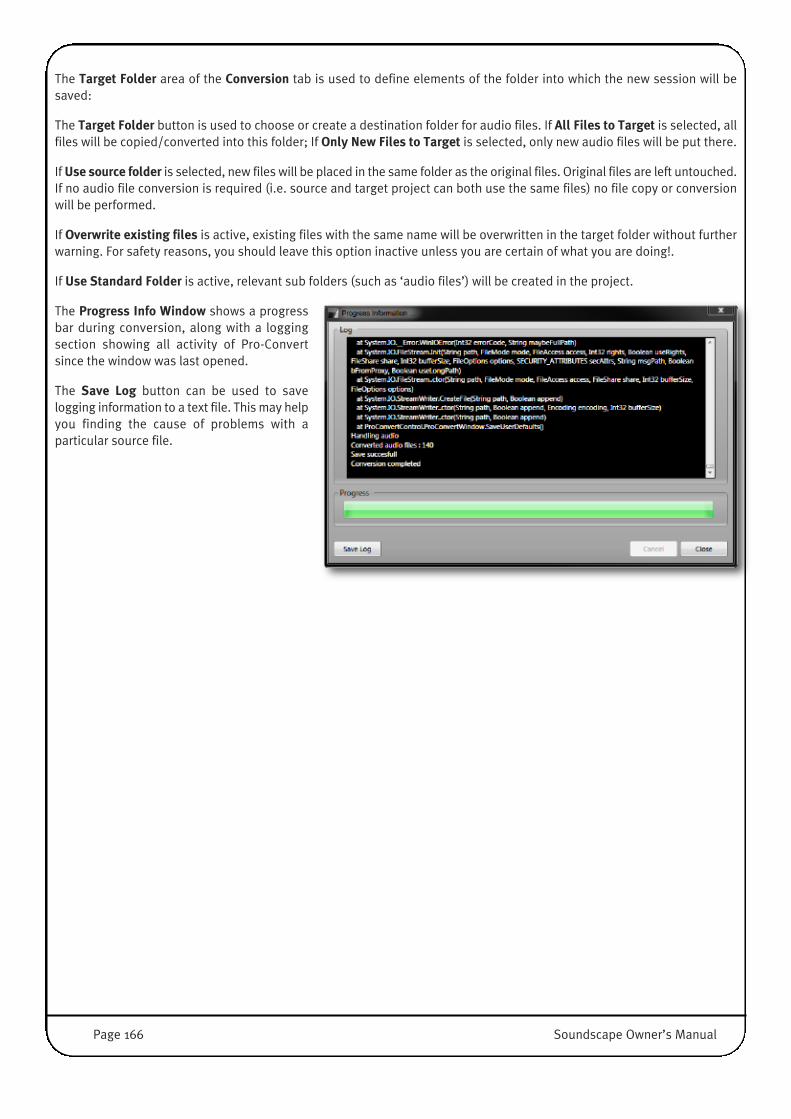
The Target Folder area of the Conversion tab is used to define elements of the folder into which the new session will besaved:
The Target Folder button is used to choose or create a destination folder for audio files. If All Files to Target is selected, allfiles will be copied/converted into this folder; If Only New Files to Target is selected, only new audio files will be put there.
If Use source folder is selected, new files will be placed in the same folder as the original files. Original files are left untouched.If no audio file conversion is required (i.e. source and target project can both use the same files) no file copy or conversionwill be performed.
If Overwrite existing files is active, existing files with the same name will be overwritten in the target folder without furtherwarning. For safety reasons, you should leave this option inactive unless you are certain of what you are doing!.
If Use Standard Folder is active, relevant sub folders (such as ‘audio files’) will be created in the project.
The Progress Info Window shows a progressbar during conversion, along with a loggingsection showing all activity of Pro-Convertsince the window was last opened.
The Save Log button can be used to savelogging information to a text file. This may helpyou finding the cause of problems with aparticular source file.
Page 166 Soundscape Owner’s Manual
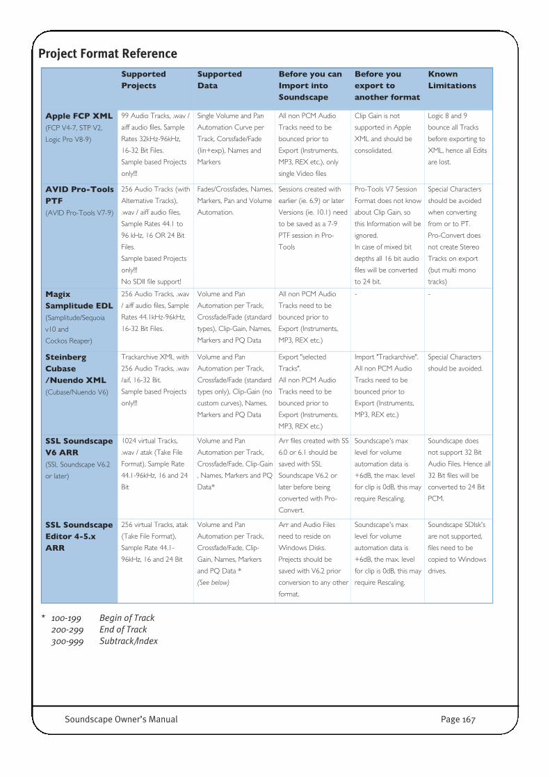
Project Format Reference
* 100-199 Begin of Track200-299 End of Track300-999 Subtrack/Index
SupportedProjects
Supported Data
Before you canImport intoSoundscape
Before youexport toanother format
KnownLimitations
Apple FCP XML (FCP V4-7, STP V2,
Logic Pro V8-9)
99 Audio Tracks, .wav /
aiff audio files, Sample
Rates 32kHz-96kHz,
16-32 Bit Files.
Sample based Projects
only!!!
Single Volume and Pan
Automation Curve per
Track, Corssfade/Fade
(lin+exp), Names and
Markers
All non PCM Audio
Tracks need to be
bounced prior to
Export (Instruments,
MP3, REX etc.), only
single Video files
Clip Gain is not
supported in Apple
XML and should be
consolidated.
Logic 8 and 9
bounce all Tracks
before exporting to
XML, hence all Edits
are lost.
AVID Pro-ToolsPTF (AVID Pro-Tools V7-9)
256 Audio Tracks (with
Alternative Tracks),
.wav / aiff audio files,
Sample Rates 44.1 to
96 kHz, 16 OR 24 Bit
Files.
Sample based Projects
only!!!
No SDII file support!
Fades/Crossfades, Names,
Markers, Pan and Volume
Automation.
Sessions created with
earlier (ie. 6.9) or later
Versions (ie. 10.1) need
to be saved as a 7-9
PTF session in Pro-
Tools
Pro-Tools V7 Session
Format does not know
about Clip Gain, so
this Information will be
ignored.
In case of mixed bit
depths all 16 bit audio
files will be converted
to 24 bit.
Special Characters
should be avoided
when converting
from or to PT.
Pro-Convert does
not create Stereo
Tracks on export
(but multi mono
tracks)
MagixSamplitude EDL(Samplitude/Sequoia
v10 and
Cockos Reaper)
256 Audio Tracks, .wav
/ aiff audio files, Sample
Rates 44.1kHz-96kHz,
16-32 Bit Files.
Volume and Pan
Automation per Track,
Crossfade/Fade (standard
types), Clip-Gain, Names,
Markers and PQ Data
All non PCM Audio
Tracks need to be
bounced prior to
Export (Instruments,
MP3, REX etc.)
- -
SteinbergCubase/Nuendo XML(Cubase/Nuendo V6)
Trackarchive XML with
256 Audio Tracks, .wav
/aif, 16-32 Bit.
Sample based Projects
only!!!
Volume and Pan
Automation per Track,
Crossfade/Fade (standard
types only), Clip-Gain (no
custom curves), Names,
Markers and PQ Data
Export "selected
Tracks".
All non PCM Audio
Tracks need to be
bounced prior to
Export (Instruments,
MP3, REX etc.)
Import "Trackarchive".
All non PCM Audio
Tracks need to be
bounced prior to
Export (Instruments,
MP3, REX etc.)
Special Characters
should be avoided.
SSL SoundscapeV6 ARR (SSL Soundscape V6.2
or later)
1024 virtual Tracks,
.wav / atak (Take File
Format), Sample Rate
44.1-96kHz, 16 and 24
Bit
Volume and Pan
Automation per Track,
Crossfade/Fade, Clip-Gain
, Names, Markers and PQ
Data*
Arr files created with SS
6.0 or 6.1 should be
saved with SSL
Soundscape V6.2 or
later before being
converted with Pro-
Convert.
Soundscape's max
level for volume
automation data is
+6dB, the max. level
for clip is 0dB, this may
require Rescaling.
Soundscape does
not support 32 Bit
Audio Files. Hence all
32 Bit files will be
converted to 24 Bit
PCM.
SSL SoundscapeEditor 4-5.xARR
256 virtual Tracks, atak
(Take File Format),
Sample Rate 44.1-
96kHz, 16 and 24 Bit
Volume and Pan
Automation per Track,
Crossfade/Fade, Clip-
Gain, Names, Markers
and PQ Data *
(See below)
Arr and Audio Files
need to reside on
Windows Disks.
Prejects should be
saved with V6.2 prior
conversion to any other
format.
Soundscape's max
level for volume
automation data is
+6dB, the max. level
for clip is 0dB, this may
require Rescaling.
Soundscape SDIsk's
are not supported,
files need to be
copied to Windows
drives.
Soundscape Owner’s Manual Page 167

VIDEO FILE PLAYER WINDOWSoundscape has a built-in video player which plays back AVI encapsulated Files synchronised to the Soundscape timeline.You can open Video Files for synchronised Playback with Soundscape using the File / Open Video File menu.
To open or hide the Video Window, toggle the View / Video Player option, or press the [V] key on your keyboard.
The following Video File Player Setup routinesare located in the Settings / Video File Playermenu.
Video System SetupClicking Setup... opens the Video Settings dialogue, which shows thecurrently selected video playback system.
Clicking the System button opens a further dialogue where another playbacksystem can be selected.
Supported Video Playback Systems Overview:• Microsoft Video for Windows (Legacy V3.3): This legacy video player
should be used with old generation video codecs (VfW Codes) or legacycapture cards like the Fast AV Master and Miro DC-30.
• DirectShow: Supports different video formats based on Direct Show (DS)software codecs including DV, HDV and others. The DirectShow playercan be used with a dual head card, where the video is displayed as apreview in the Video Window and full screen on the second monitor.
• DPS Reality and Matrox Digisuite: Supports playback through legacyDPS and Matrox Broadcast Cards.
Clicking the Settings button in the Video Settings dialogue opens the Frame Delay setup, where a video processing delaycan be set from 1 to 20 Frames. This is used to compensate for delays introduced by graphics or video cards. Soundscape willeffectively play the Video early by the amount of frames that have been set.
Page 168 Soundscape Owner’s Manual

Video SettingsOffset�Clicking Offset... in the Video File Player submenu displays the Video File Offset window.
The easiest way to set the video file offset is to make sure that the SMPTE Offset in the Settingsmenu is set to 00:00:00:00. This will ensure that the first frame in the AVI file will be displayed.If you have captured with a timecode superimposed, you can simply read this from the videowindow and type this in as the video file offset. If not, you may have to identify a significantevent in the video that can be related to the audio in some way.
In any case, you must ensure that the SMPTE Format (Frame Rate) matches the timecode formatof the captured video. To check that there is synchronisation from the start to the end of thevideo file, move the Current Locator and check that the video shows the same timecode asSoundscape’s SMPTE readout.
The Save to SVO File button allows you to save the offset as an .SVO file in the same PC folder and under the same name asthe video file itself, so that the next time you load the file, the offset will be automatically set. If it is not possible to write tothat location (i.e., if the path is ‘read only’ under Windows), the .SVO file will be stored in the C:\Soundscape\AVI folder.
With video files captured at a lower Frame Rate than the current Soundscape SMPTE Format, you will find that as the playbackof Soundscape advances, there will be missing frames in the video file, so the same frame is displayed twice. However, thereshould be no overall synchronisation error between video and audio. If you do find a slippage, then the video file may havebeen captured with dropped frames.
Display SizeWhen the mouse pointer is on Display Size in the Video File Player submenu, a further submenu is displayed:
• Auto: Sets the video window size automatically; Normally Soundscape will try to display the original size in the videowindow, if the window wouldn't into the currently selected screen resolution the video window is resized to 1/2 or 1/4 ofthe original size.
• 1/4, 1/2, 1/1 or 2/1: Will resize the window to a fixed size, as a ratio of the original size of the video file.
Always on topIf Always on top is selected, the Video File Player window will always remain visible on top of any other window, even if thatother window is active (except if that other window is also set to be Always on top. In Soundscape this could be the Mixer orBig Current Time window).
Soundscape Owner’s Manual Page 169
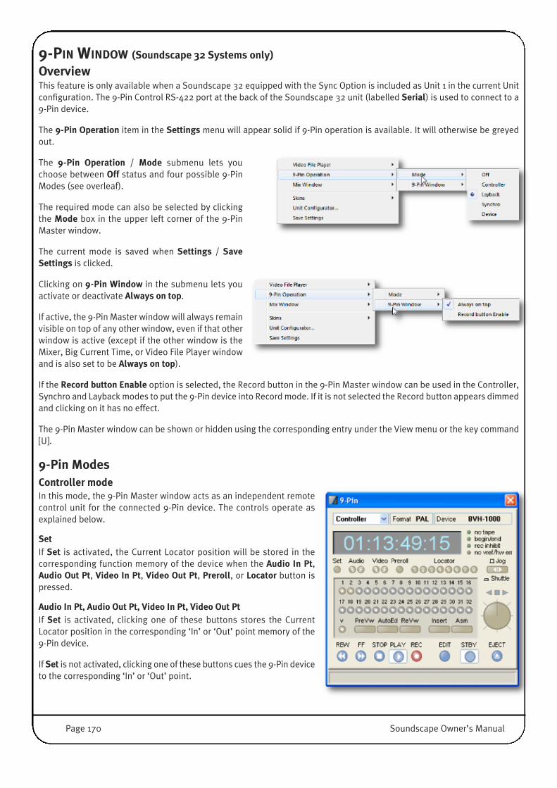
9-PIN WINDOW (Soundscape 32 Systems only)
OverviewThis feature is only available when a Soundscape 32 equipped with the Sync Option is included as Unit 1 in the current Unitconfiguration. The 9-Pin Control RS-422 port at the back of the Soundscape 32 unit (labelled Serial) is used to connect to a9-Pin device.
The 9-Pin Operation item in the Settings menu will appear solid if 9-Pin operation is available. It will otherwise be greyedout.
The 9-Pin Operation / Mode submenu lets youchoose between Off status and four possible 9-PinModes (see overleaf).
The required mode can also be selected by clickingthe Mode box in the upper left corner of the 9-PinMaster window.
The current mode is saved when Settings / SaveSettings is clicked.
Clicking on 9-Pin Window in the submenu lets youactivate or deactivate Always on top.
If active, the 9-Pin Master window will always remainvisible on top of any other window, even if that otherwindow is active (except if the other window is theMixer, Big Current Time, or Video File Player windowand is also set to be Always on top).
If the Record button Enable option is selected, the Record button in the 9-Pin Master window can be used in the Controller,Synchro and Layback modes to put the 9-Pin device into Record mode. If it is not selected the Record button appears dimmedand clicking on it has no effect.
The 9-Pin Master window can be shown or hidden using the corresponding entry under the View menu or the key command[U].
9-Pin ModesController modeIn this mode, the 9-Pin Master window acts as an independent remotecontrol unit for the connected 9-Pin device. The controls operate asexplained below.
SetIf Set is activated, the Current Locator position will be stored in thecorresponding function memory of the device when the Audio In Pt,Audio Out Pt, Video In Pt, Video Out Pt, Preroll, or Locator button ispressed.
Audio In Pt, Audio Out Pt, Video In Pt, Video Out PtIf Set is activated, clicking one of these buttons stores the CurrentLocator position in the corresponding ‘In’ or ‘Out’ point memory of the9-Pin device.
If Set is not activated, clicking one of these buttons cues the 9-Pin deviceto the corresponding ‘In’ or ‘Out’ point.
Page 170 Soundscape Owner’s Manual

PrerollIf Set is activated, clicking this button stores the ‘seconds:frames’ portion of the Current Locator position in the Prerollmemory of the device.
If Set is not activated, clicking this button cues the device to the Preroll position.
Locator 1-8If Set is activated, clicking one of these buttons stores the Current Locator position in the corresponding Locator memory.
If Set is not activated, clicking one of these buttons cues the 9-Pin device to the corresponding Locator point.
Audio track arming 1-32 These buttons control the track arming status of the 9-Pin device’s corresponding audio tracks. By default, only the first twoanalogue audio tracks can be armed.
You can specify the number of analogue or digital audio tracks for each device by adding a device specific line to Soundscape’s.INI file. See below for more details.
Video track armingThe V button controls the track arming status of the 9-Pin device’s video track.
Preview, Auto Edit, Review, Insert, Assemble, Edit, Standby, Eject These buttons control the corresponding functions of the device.
Rewind, Fast Forward, Stop, Play, Record These buttons control the corresponding tape transport functions of the 9-Pin device.
The REC button can only be used if the Record button Enable option in Settings / 9-Pin Operation / 9-Pin Window is selected.If it is not selected the REC button appears dimmed, and clicking it has no effect.
Jog/Shuttle Clicking this button toggles the mode of the ‘Jog/Shuttle’ wheel.
Layback modeIn this mode, in addition to all the functionality of the Controller mode,the 9-Pin device is also controlled by certain Soundscape operations:
Tape transport commandsAll Soundscape tape transport commands are simultaneously sent tothe device.
In case of Rewind and Forward commands, Soundscape actually slavesthe Soundscape 32 unit to the 9-Pin device, in order to keep both in syncduring wind operations. Successive Rewind/Forward button presses willresult in faster/slower shuttle/wind speeds.
However, in the case of Play and Record commands, in order tosynchronize Soundscape 32 properly to the 9-Pin device, the SMPTEposition of the device must be fed to the MTC input of Soundscape 32using an external SMPTE/MTC converter, and Soundscape 32 must beset to MTC Chase Slave or MTC Trigger Slave mode, depending on theMaster Clock source.
Current Locator jumpsAll Current Locator jumps made in Soundscape are simultaneously sent to the 9-Pin device, so that synchronisation ismaintained.
Soundscape Owner’s Manual Page 171
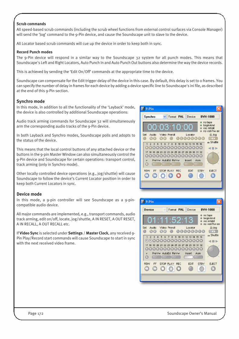
Scrub commandsAll speed-based scrub commands (including the scrub wheel functions from external control surfaces via Console Manager)will send the ‘Jog’ command to the 9-Pin device, and cause the Soundscape unit to slave to the device.
All Locator based scrub commands will cue up the device in order to keep both in sync.
Record Punch modesThe 9-Pin device will respond in a similar way to the Soundscape 32 system for all punch modes. This means thatSoundscape's Left and Right Locators, Auto Punch In and Auto Punch Out buttons also determine the way the device records.
This is achieved by sending the ‘Edit On/Off’ commands at the appropriate time to the device.
Soundscape can compensate for the Edit trigger delay of the device in this case. By default, this delay is set to 0 frames. Youcan specify the number of delay in frames for each device by adding a device specific line to Soundscape's ini file, as describedat the end of this 9-Pin section.
Synchro modeIn this mode, in addition to all the functionality of the ‘Layback’ mode,the device is also controlled by additional Soundscape operations:
Audio track arming commands for Soundscape 32 will simultaneouslyarm the corresponding audio tracks of the 9-Pin device.
In both Layback and Synchro modes, Soundscape polls and adopts tothe status of the device.
This means that the local control buttons of any attached device or thebuttons in the 9-pin Master Window can also simultaneously control the9-Pin device and Soundscape for certain operations: transport control,track arming (only in Synchro mode).
Other locally controlled device operations (e.g., jog/shuttle) will causeSoundscape to follow the device’s Current Locator position in order tokeep both Current Locators in sync.
Device modeIn this mode, a 9-pin controller will see Soundscape as a 9-pin-compatible audio device.
All major commands are implemented, e.g., transport commands, audiotrack arming, edit on/off, locate, jog/shuttle, A IN RESET, A OUT RESET,A IN RECALL, A OUT RECALL etc.
If Video Sync is selected under Settings / Master Clock, any received 9-Pin Play/Record start commands will cause Soundscape to start in syncwith the next received video frame.
Page 172 Soundscape Owner’s Manual
Preparation: Modifying the .INI file for 9-Pin operationMaster modesFor every device model, a line should be added to Soundscapes INI file under the [9PinWnd] section. The INI file is locatedat: C:\Soundscape\ssEditorDef.ini and can be opened with a standard Windows text editor. This line must contain devicespecific information that is used by Soundscape:
Currently the following three values need to be specified per device attached:
• Number of analogue audio tracks (0...4).
• Number of digital audio tracks (0...32).
NOTE: A device cannot have both analogue and digital audio tracks, so one of the values must be zero.
• Edit trigger delay, expressed in frames (0...99).
For example, if you are using a Sony BVW-75 that has 4 analogue audio tracks, and its Edit trigger delay is set to 3 frames,this line must be added:
BVW-75=4 0 3
Please note that this line must be added under the [9PinWnd] section, and the device model name must exactly match thedevice name displayed in the 9-Pin Master Window.
If the [9PinWnd] section does not exist in the INI file yet, then a Save Settings operation must be executed first .
Device modeAs a default, the 9-pin device mode uses ‘FxDE’ as the Soundscape device ID. A different Soundscape device ID can be set(e.g., ‘5178’) by adding the following line to the INI file under the [9PinWnd] section:
S9PinDevID=0x5178
Please note that this line must be added under the [9PinWnd] section.
If the [9PinWnd] section does not exist in the INI file yet, then a Save Settings operation must be executed first .
Soundscape Owner’s Manual Page 173
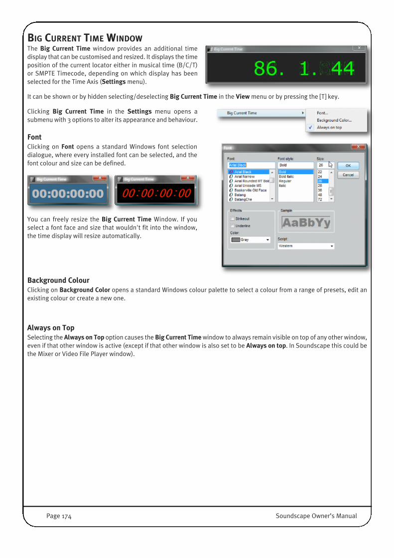
BIG CURRENT TIME WINDOWThe Big Current Time window provides an additional timedisplay that can be customised and resized. It displays the timeposition of the current locator either in musical time (B/C/T)or SMPTE Timecode, depending on which display has beenselected for the Time Axis (Settings menu).
It can be shown or by hidden selecting/deselecting Big Current Time in the View menu or by pressing the [T] key.
Clicking Big Current Time in the Settings menu opens asubmenu with 3 options to alter its appearance and behaviour.
FontClicking on Font opens a standard Windows font selectiondialogue, where every installed font can be selected, and thefont colour and size can be defined.
You can freely resize the Big Current Time Window. If youselect a font face and size that wouldn't fit into the window,the time display will resize automatically.
Background ColourClicking on Background Color opens a standard Windows colour palette to select a colour from a range of presets, edit anexisting colour or create a new one.
Always on TopSelecting the Always on Top option causes the Big Current Time window to always remain visible on top of any other window,even if that other window is active (except if that other window is also set to be Always on top. In Soundscape this could bethe Mixer or Video File Player window).
Page 174 Soundscape Owner’s Manual
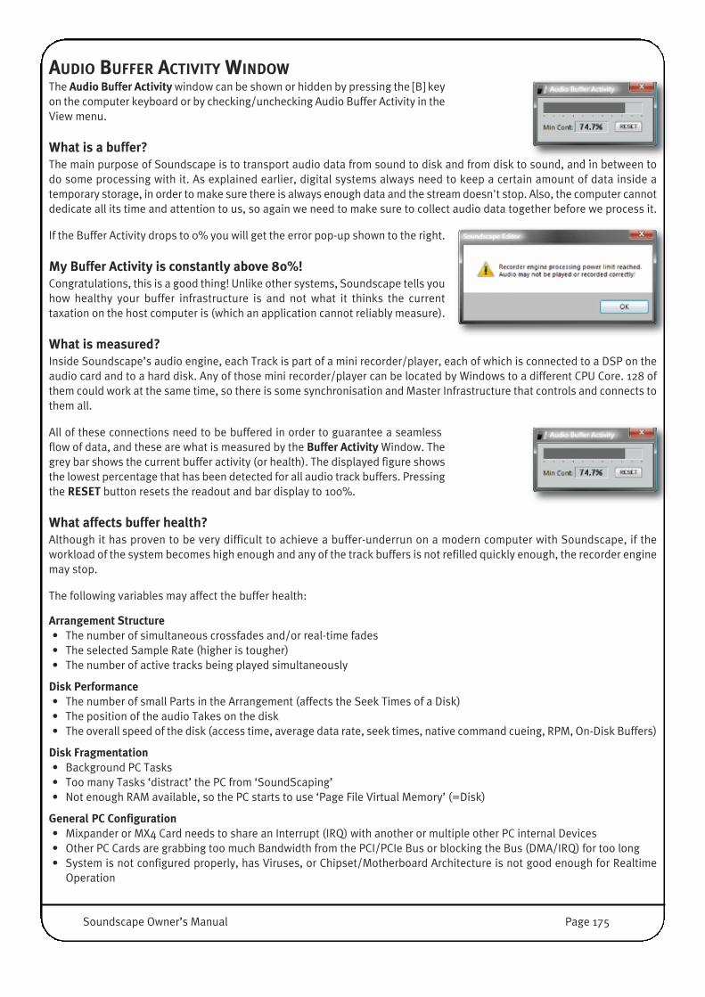
AUDIO BUFFER ACTIVITY WINDOWThe Audio Buffer Activity window can be shown or hidden by pressing the [B] keyon the computer keyboard or by checking/unchecking Audio Buffer Activity in theView menu.
What is a buffer?The main purpose of Soundscape is to transport audio data from sound to disk and from disk to sound, and in between todo some processing with it. As explained earlier, digital systems always need to keep a certain amount of data inside atemporary storage, in order to make sure there is always enough data and the stream doesn't stop. Also, the computer cannotdedicate all its time and attention to us, so again we need to make sure to collect audio data together before we process it.
If the Buffer Activity drops to 0% you will get the error pop-up shown to the right.
My Buffer Activity is constantly above 80%!Congratulations, this is a good thing! Unlike other systems, Soundscape tells youhow healthy your buffer infrastructure is and not what it thinks the currenttaxation on the host computer is (which an application cannot reliably measure).
What is measured?Inside Soundscape’s audio engine, each Track is part of a mini recorder/player, each of which is connected to a DSP on theaudio card and to a hard disk. Any of those mini recorder/player can be located by Windows to a different CPU Core. 128 ofthem could work at the same time, so there is some synchronisation and Master Infrastructure that controls and connects tothem all.
All of these connections need to be buffered in order to guarantee a seamlessflow of data, and these are what is measured by the Buffer Activity Window. Thegrey bar shows the current buffer activity (or health). The displayed figure showsthe lowest percentage that has been detected for all audio track buffers. Pressingthe RESET button resets the readout and bar display to 100%.
What affects buffer health?Although it has proven to be very difficult to achieve a buffer-underrun on a modern computer with Soundscape, if theworkload of the system becomes high enough and any of the track buffers is not refilled quickly enough, the recorder enginemay stop.
The following variables may affect the buffer health:
Arrangement Structure• The number of simultaneous crossfades and/or real-time fades• The selected Sample Rate (higher is tougher)• The number of active tracks being played simultaneously
Disk Performance• The number of small Parts in the Arrangement (affects the Seek Times of a Disk)• The position of the audio Takes on the disk• The overall speed of the disk (access time, average data rate, seek times, native command cueing, RPM, On-Disk Buffers)
Disk Fragmentation• Background PC Tasks• Too many Tasks ‘distract’ the PC from ‘SoundScaping’• Not enough RAM available, so the PC starts to use ‘Page File Virtual Memory’ (=Disk)
General PC Configuration• Mixpander or MX4 Card needs to share an Interrupt (IRQ) with another or multiple other PC internal Devices• Other PC Cards are grabbing too much Bandwidth from the PCI/PCIe Bus or blocking the Bus (DMA/IRQ) for too long• System is not configured properly, has Viruses, or Chipset/Motherboard Architecture is not good enough for Realtime
Operation
Soundscape Owner’s Manual Page 175

What you can do to avoid Buffer underuns...• Raise the Native Mixer Elements Sample Buffer Size (in the Settings / Preferences / Mixer menu) to increase the size
of the buffers;
• Reduce the amount of random seeking the disk has to perform by using the Mixdown or Consolidate Process tools togenerate new, consecutive Takes;
• Reduce the number of real-time fades by consolidating to a new Take which includes those fades;
• Use a lower sample rate;
• Try another PCI/PCIe Slot for the Mixpander or MX4 Card;
• Remove other cards from the system and check if the behaviour improves;
• Replace the disk with a faster one, especially with bigger onboard buffers and technologies like NCQ (native commandcueing);
• Replace the whole PC and get one with more CPU cores and a faster memory subsystem, try to buy a known good systemconfiguration including components from well known quality brands.
Page 176 Soundscape Owner’s Manual

5. Menu Reference
This chapter describes every function and feature in Soundscape in the order they appear inside the main menu structure.Some menus and entries are only accessible when Soundscape is in Stop Mode. Whenever a menu is not accessible duringPlay/Record or certain entries are greyed out/dimmed – please Stop Soundscape first.
Many menu entries are self explanatory and follow a standard Windows nomenclature, while others might need someexplanation and background information before they can be used intuitively. It might therefore be a good idea to work yourway through this chapter at some point (probably on a rainy Saturday) with the system switched on.
The File Manager window relies completely on ‘context sensitive’ mouse interaction and many features of the File Managercannot be accessed through menus.
FILE MENUWith the File Menu, Arrangements and Mixers can be created, loaded and saved.An Arrangement can also be appended to the current one.
There are also options to import or export to MP3, Pro Tools, SDR and OMFformats, and to open or close Video files and tempo maps.
Finally, Soundscape can be closed from this menu.
The File Menu cannot be accessed while Soundscape is in Play or Record Mode.
NOTE: For the MP3 import/export to be active, the required Fraunhofer MP3codecs needs to be installed. The OMF export option is an optional plug-in.
ArrangementsClicking New Arr... willcreate a new, empty
Arrangement window. If an Arrangement that has been edited is already active,the dialogue box shown right will appear, giving you the option to save it beforeclosure.
Soundscape Owner’s Manual Page 177

Open Arr... opens a standard Windows dialogue box. If an Arrangementis already active and has been edited since it was last saved, the samedialogue box mentioned above will appear.
If any Takes used in the Arrangement are not present on the Domain RootFolders, the warning shown right will be displayed. If you proceed, any Partsthat reference Takes that are not present will be removed from the loadedArrangement. If you have backed up these Takes to another drive it isadvisable to import them to the relevant folder, then open the Arrangementagain. Otherwise, the Arrangement will still play correctly except for themissing Parts, but if you save it under the same name the missing Parts will notbe referenced anymore.
Append Arr... opens a Standard Windows File Browser to select anArrangement to be appended to the active one.
The chosen Arrangement will be appended at the Current Locator position, so the Current Locator should be placed at thedesired song position before using this option. If any Takes used in the appended Arrangement are not present on the relevantfolder, the warning described above will be displayed.
In addition, if Part overlaps are not allowed (Settings / Preferences / Arrangement / Overlapping Parts (for new edits)), anyParts in the appended Arrangement which would overlap Parts in the current Arrangement will not be loaded.
Parts which would be out of range are not loaded either. In such cases thewarning shown right will be displayed.
All the parameters saved within an Arrangement file will be loaded from theappended Arrangement, including Sample Rate, Time Code format, SMPTEoffset, Varispeed setting, Record setup, Automation setup, Tempo, and TimeSignature. Therefore, if you wish to retain the settings of the currentArrangement, save it, load the other Arrangement first and then append thecurrent one.
To make sure that overlaps do not occur when appending an Arrangement if they are not allowed, it is sometimes necessaryto move all Parts of the current Arrangement to empty virtual tracks, while not altering the timing of any of these Parts. Thiscan be done easily with the Move Vertical tool.
Page 178 Soundscape Owner’s Manual

With Save Arr... the current Arrangement is saved and the storedVersion overwritten. Arrangements include Project Information like
Sample Rate, Frame Rate, Tempo, SMPTE offset, Varispeed, L and R locators, Markers, Punch and Loop button status, Settingsinside Record setup / Automation setup and the assigned Record/Process folder.
Use Save Arr as... to save a copy of the Arrangement or to save a newArrangement for the first time. A standard file Browser will open:
Saving selected Parts as an ArrangementIf any Part is selected when you Save Arr as..., a dialogue box will appear, shown right. If youclick No, the whole Arrangement will be saved, as described above. If you click Yes, only theselected Parts will be saved, with their individual parameters such as time position andvirtual track position in the Arrangement, and track assignment, but without all the usualArrangement parameters listed above.
This feature is especially useful if you wish to save Parts with an embedded snap point,quickly save a version of the current Arrangement including the muted Parts or the activeParts only, by typing [Shift]+[M] (Select Muted Parts) or [Shift]+[M] followed by [Shift]+[X](Invert Part selections) or simply to save a Multi Track Jingle, Opener or Sound FX you needto re-use in future Arrangements.
In order to keep compatibility with legacy SSL Soundscape Editorsystems, you can Save Arr As V5.1 compatible format. This option is
only available when no WAV/BWF Takes are referenced by any Parts inside the Arrangement (in other words only theSoundscape .ATAK Format is used).
Pro-Convert ExportIt is possible to import and export a variety of DAW formats toArrangements. Save Arr and Pro-Convert to provides a quick-savefunction, and Save Arr and Pro-Convert provides a number of exportoptions. These functions are described in full in the Project Conversionsection of this guide.
Soundscape Owner’s Manual Page 179
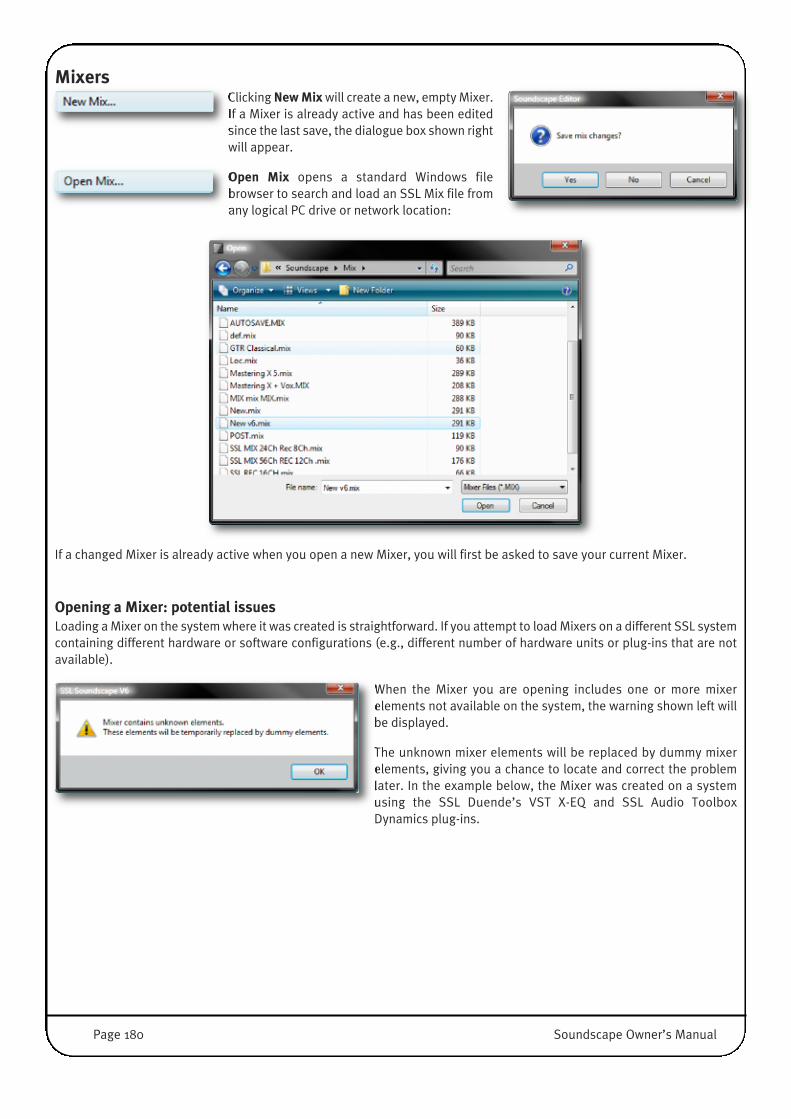
MixersClicking New Mix will create a new, empty Mixer.If a Mixer is already active and has been editedsince the last save, the dialogue box shown rightwill appear.
Open Mix opens a standard Windows filebrowser to search and load an SSL Mix file fromany logical PC drive or network location:
If a changed Mixer is already active when you open a new Mixer, you will first be asked to save your current Mixer.
Opening a Mixer: potential issuesLoading a Mixer on the system where it was created is straightforward. If you attempt to load Mixers on a different SSL systemcontaining different hardware or software configurations (e.g., different number of hardware units or plug-ins that are notavailable).
When the Mixer you are opening includes one or more mixerelements not available on the system, the warning shown left willbe displayed.
The unknown mixer elements will be replaced by dummy mixerelements, giving you a chance to locate and correct the problemlater. In the example below, the Mixer was created on a systemusing the SSL Duende’s VST X-EQ and SSL Audio ToolboxDynamics plug-ins.
Page 180 Soundscape Owner’s Manual
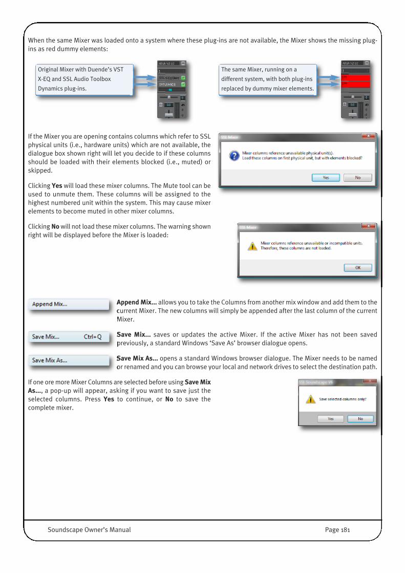
When the same Mixer was loaded onto a system where these plug-ins are not available, the Mixer shows the missing plug-ins as red dummy elements:
If the Mixer you are opening contains columns which refer to SSLphysical units (i.e., hardware units) which are not available, thedialogue box shown right will let you decide to if these columnsshould be loaded with their elements blocked (i.e., muted) orskipped.
Clicking Yes will load these mixer columns. The Mute tool can beused to unmute them. These columns will be assigned to thehighest numbered unit within the system. This may cause mixerelements to become muted in other mixer columns.
Clicking No will not load these mixer columns. The warning shownright will be displayed before the Mixer is loaded:
Append Mix... allows you to take the Columns from another mix window and add them to thecurrent Mixer. The new columns will simply be appended after the last column of the currentMixer.
Save Mix... saves or updates the active Mixer. If the active Mixer has not been savedpreviously, a standard Windows ‘Save As’ browser dialogue opens.
Save Mix As... opens a standard Windows browser dialogue. The Mixer needs to be namedor renamed and you can browse your local and network drives to select the destination path.
If one ore more Mixer Columns are selected before using Save MixAs..., a pop-up will appear, asking if you want to save just theselected columns. Press Yes to continue, or No to save thecomplete mixer.
Original Mixer with Duende’s VST
X-EQ and SSL Audio Toolbox
Dynamics plug-ins.
The same Mixer, running on a
different system, with both plug-ins
replaced by dummy mixer elements.
Soundscape Owner’s Manual Page 181

XPro Import/ExportThe XPro Import/Export Functionsoption allow audio data conversion toand from a variety of formats. At themoment the list of available formatsincludes: Fraunhofer MPEG Layer-3, ProTools Project, SDR Projects.
Note that some elements of this menu are only present for legacy purposes. Import and export of a wider range of DAWformats is available via the File menu’s Save Arr and Pro-Convert options. For more information, please refer to the‘Project Conversion’ section.
OMF Composition Import/Export and OMF Audio Import options are also available, for which separate software must beinstalled. All available XPro component options are organised in a submenu.
OMF Composition Import, OMF Composition Export, and OMF Audio Import options areavailable if you have installed the optional OMF Import/Export Plug-In Module. A passwordmust be entered under the Options menu.
After selecting the OMF CompositionImport, a standard Windows filebrowse dialogue appears, which youcan use to locate and select an OMFComposition stored on any logical PCdrive.
If there are any Parts in the Arrangewindow, a message box will appear andwarn you that these Parts will beremoved from the Arrangement.
Click Cancel if you need to save the current Arrangement first, otherwise click OK.
After selection, clicking Open will open a dialogue box (shown left) with audio importoptions: • Load minimum required audio data imports only the audio used by the Parts • Load all available audio data imports the whole Takes even if the Parts are shorter• Load audio data with additional handles imports the audio used by the Parts plus
handles.
Clicking OK will start the import and a progress Window will be displayed.
Page 182 Soundscape Owner’s Manual
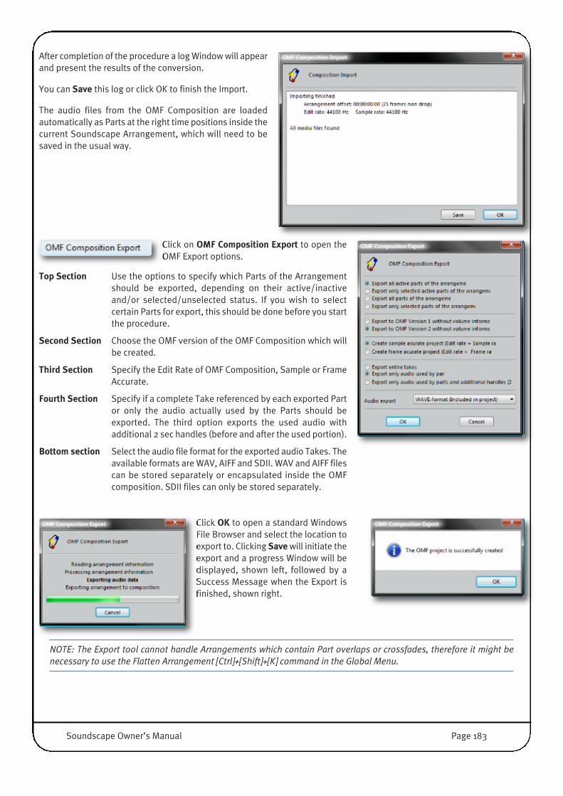
After completion of the procedure a log Window will appearand present the results of the conversion.�
You can Save this log or click OK to finish the Import.
The audio files from the OMF Composition are loadedautomatically as Parts at the right time positions inside thecurrent Soundscape Arrangement, which will need to besaved in the usual way.
Click on OMF Composition Export to open theOMF Export options.
Top Section Use the options to specify which Parts of the Arrangementshould be exported, depending on their active/inactiveand/or selected/unselected status. If you wish to selectcertain Parts for export, this should be done before you startthe procedure.
Second Section Choose the OMF version of the OMF Composition which willbe created.
Third Section Specify the Edit Rate of OMF Composition, Sample or FrameAccurate.
Fourth Section Specify if a complete Take referenced by each exported Partor only the audio actually used by the Parts should beexported. The third option exports the used audio withadditional 2 sec handles (before and after the used portion).
Bottom section Select the audio file format for the exported audio Takes. Theavailable formats are WAV, AIFF and SDII. WAV and AIFF filescan be stored separately or encapsulated inside the OMFcomposition. SDII files can only be stored separately.
Click OK to open a standard WindowsFile Browser and select the location toexport to. Clicking Save will initiate theexport and a progress Window will bedisplayed, shown left, followed by aSuccess Message when the Export isfinished, shown right.
NOTE: The Export tool cannot handle Arrangements which contain Part overlaps or crossfades, therefore it might benecessary to use the Flatten Arrangement [Ctrl]+[Shift]+[K] command in the Global Menu.
Soundscape Owner’s Manual Page 183
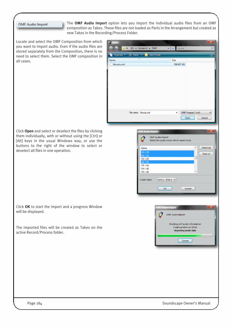
The OMF Audio Import option lets you import the individual audio files from an OMFcomposition as Takes. These files are not loaded as Parts in the Arrangement but created asnew Takes in the Recording/Process Folder.
Locate and select the OMF Composition from whichyou want to import audio. Even if the audio files arestored separately from the Composition, there is noneed to select them. Select the OMF composition inall cases.
Click Open and select or deselect the files by clickingthem individually, with or without using the [Ctrl] or[Alt] keys in the usual Windows way, or use thebuttons to the right of the window to select ordeselect all files in one operation.
Click OK to start the import and a progress Windowwill be displayed.
The imported files will be created as Takes on theactive Record/Process folder.
Page 184 Soundscape Owner’s Manual
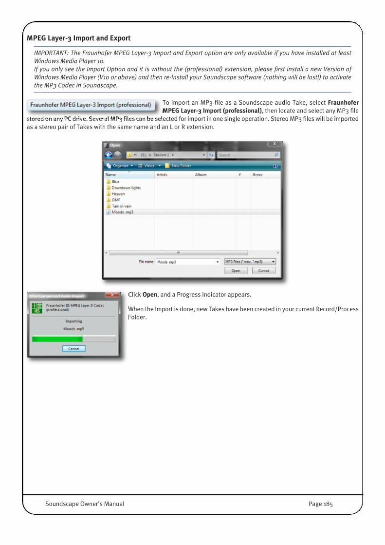
MPEG Layer-3 Import and Export
IMPORTANT: The Fraunhofer MPEG Layer-3 Import and Export option are only available if you have installed at leastWindows Media Player 10.If you only see the Import Option and it is without the (professional) extension, please first install a new Version ofWindows Media Player (V10 or above) and then re-Install your Soundscape software (nothing will be lost!) to activatethe MP3 Codec in Soundscape.
To import an MP3 file as a Soundscape audio Take, select FraunhoferMPEG Layer-3 Import (professional), then locate and select any MP3 file
stored on any PC drive. Several MP3 files can be selected for import in one single operation. Stereo MP3 files will be importedas a stereo pair of Takes with the same name and an L or R extension.
Click Open, and a Progress Indicator appears.
When the Import is done, new Takes have been created in your current Record/ProcessFolder.
Soundscape Owner’s Manual Page 185

Selected Takes (all audio Takesselected in the File Manager) or
Active Takes (all audio Takes referenced by Parts in the current Arrangement) can beenabled for export by selecting Fraunhofer MPEG Layer-3 Export (professional), andclicking OK in the window which appears (shown right)
In the next Dialogue, the Output file format needs to be selected:
• Export as WAV Files: Allows to save as compressed MP3 Audio inside a .WavContainer
• Export as MP3 Files: Saves the file inside a standard MP3 Container• Bitrate Selection: Select Bitrate, Sample Rate and Mono/Stereo Format options• Generate Stereo Files: Takes with same name and L/R extension will be exported
as a Stereo MP3 File• Include BWF Chunk: A BWF-chunk is derived from the Take properties comments
field and includes the original Time Stamp (Start Point). (Only available if Exportas WAV Files is selected.)
In the bottom section you can view and Change the currently selected DestinationFolder.
Click OK. to start the Export. A Progress indicator will be displayed until the Export isdone.
Page 186 Soundscape Owner’s Manual

ProTools Session Import and ExportThe ProTools Project Import Function enables Soundscape to read AVID Protools©Projects, created with earlier Versions of this DAW Software (V3.-V5.x).
IMPORTANT: If you need to exchange ProTools Projects in a later Format (6,7,8.x) you can purchase SSL Pro-Convert,which translates Soundscape Arrangements into the latest ProTools Session formats and vice versa. For moreInformation about SSL Pro-Convert, please visit the product website at:
www.solidstatelogic.com/music/pro-convert/index.asp Note that Pro-Convert is already embedded in Soundscape 6.2 and simply needs a password to unlock it.
NOTE: There is no need for a password to authorise the ProTools Import/Export function, even though there is a line forentering one in the Optional Modules dialogue box .
Click on ProTools Project Import and browse to theSession you want to import.
Select the Project and click OK.
If there are any Parts in the Arrange window, a message box will warn youthat these Parts will be removed from the Arrangement. Click Cancel if youneed to save the current Arrangement before proceeding, otherwise click OK.
In Soundscape you don't have to select aDestination, the Project Import will go intothe currently selected Record/ProcessFolder.
Click OK.
A Progress Window will appear until the Import is complete.
The audio files from the Pro Tools Project will be loaded automatically as Partsat the required time positions in the current Arrangement which will then needto be saved in the usual way.
Soundscape Owner’s Manual Page 187
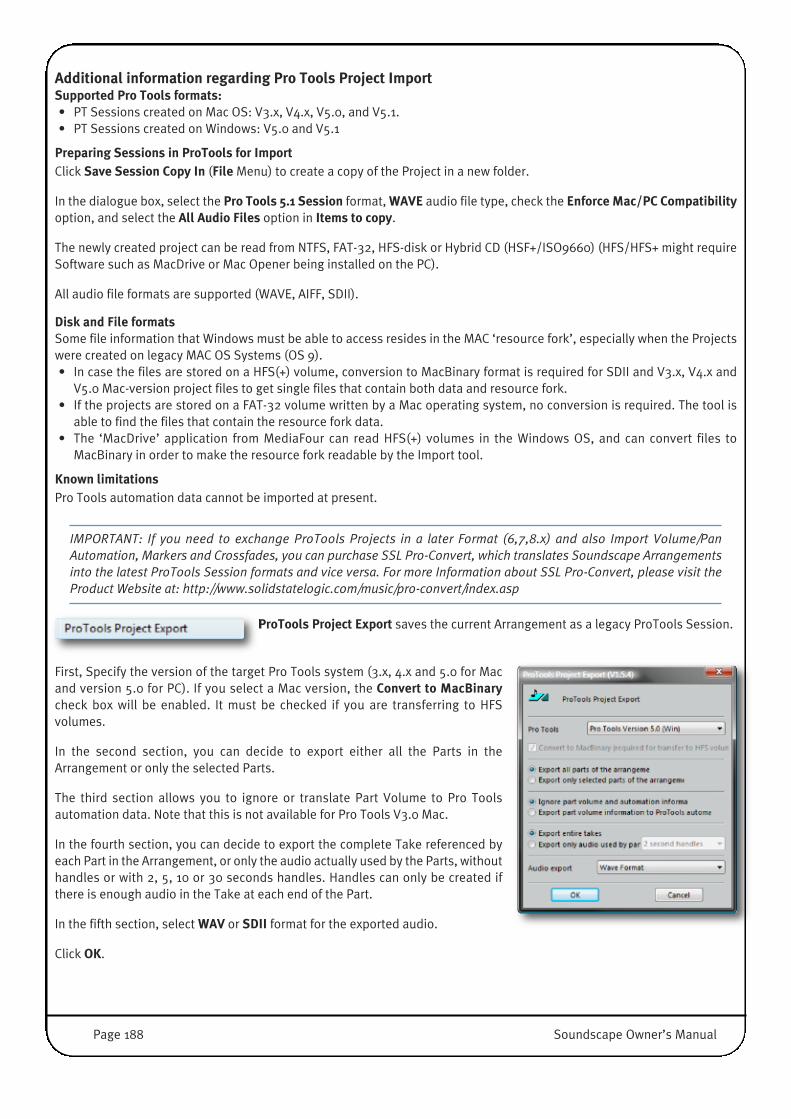
Additional information regarding Pro Tools Project ImportSupported Pro Tools formats:• PT Sessions created on Mac OS: V3.x, V4.x, V5.0, and V5.1.• PT Sessions created on Windows: V5.0 and V5.1
Preparing Sessions in ProTools for ImportClick Save Session Copy In (File Menu) to create a copy of the Project in a new folder.
In the dialogue box, select the Pro Tools 5.1 Session format, WAVE audio file type, check the Enforce Mac/PC Compatibilityoption, and select the All Audio Files option in Items to copy.
The newly created project can be read from NTFS, FAT-32, HFS-disk or Hybrid CD (HSF+/ISO9660) (HFS/HFS+ might requireSoftware such as MacDrive or Mac Opener being installed on the PC).
All audio file formats are supported (WAVE, AIFF, SDII).
Disk and File formatsSome file information that Windows must be able to access resides in the MAC ‘resource fork’, especially when the Projectswere created on legacy MAC OS Systems (OS 9).• In case the files are stored on a HFS(+) volume, conversion to MacBinary format is required for SDII and V3.x, V4.x and
V5.0 Mac-version project files to get single files that contain both data and resource fork.• If the projects are stored on a FAT-32 volume written by a Mac operating system, no conversion is required. The tool is
able to find the files that contain the resource fork data.• The ‘MacDrive’ application from MediaFour can read HFS(+) volumes in the Windows OS, and can convert files to
MacBinary in order to make the resource fork readable by the Import tool.
Known limitationsPro Tools automation data cannot be imported at present.
IMPORTANT: If you need to exchange ProTools Projects in a later Format (6,7,8.x) and also Import Volume/PanAutomation, Markers and Crossfades, you can purchase SSL Pro-Convert, which translates Soundscape Arrangementsinto the latest ProTools Session formats and vice versa. For more Information about SSL Pro-Convert, please visit theProduct Website at: http://www.solidstatelogic.com/music/pro-convert/index.asp
ProTools Project Export saves the current Arrangement as a legacy ProTools Session.
First, Specify the version of the target Pro Tools system (3.x, 4.x and 5.0 for Macand version 5.0 for PC). If you select a Mac version, the Convert to MacBinarycheck box will be enabled. It must be checked if you are transferring to HFSvolumes.
In the second section, you can decide to export either all the Parts in theArrangement or only the selected Parts.
The third section allows you to ignore or translate Part Volume to Pro Toolsautomation data. Note that this is not available for Pro Tools V3.0 Mac.
In the fourth section, you can decide to export the complete Take referenced byeach Part in the Arrangement, or only the audio actually used by the Parts, withouthandles or with 2, 5, 10 or 30 seconds handles. Handles can only be created ifthere is enough audio in the Take at each end of the Part.
In the fifth section, select WAV or SDII format for the exported audio.
Click OK.
Page 188 Soundscape Owner’s Manual

Choose the Destination in the Windows File Browser and give the Session a name...
Click Save.
The Export will start and a Progress Window appears until the export is finished.
Additional information regarding Pro Tools ExportKnown limitations• Soundscape automation data cannot be exported to Pro Tools at present. However Part volume information is translated
as Pro Tools automation data.• The Export tool cannot handle Arrangements which contain Part overlaps or crossfades, you may need to Flatten the
Arrangement and/or use the Consolidate Tool on crossfaded Part Sections before export.
IMPORTANT: If you need to exchange ProTools Projects in a later Format (6,7,8.x) and also Export Volume/PanAutomation, Markers and Crossfades, you can purchase SSL Pro-Convert, which translates Soundscape Arrangementsinto the latest ProTools Session formats and vice versa. For more Information about SSL Pro-Convert, please visit theProduct Website at: http://www.solidstatelogic.com/music/pro-convert/index.asp
�
Soundscape Owner’s Manual Page 189

SDR Project Import and ExportThe SDR Project Import option can be used to locate, select and import an SDR Project(Mackie SDR/MDR/HDR24/96 format) stored on any PC logical drive.
Click Open.
If there are any Parts in the Arrange window, a message box will warn youthat these Parts will be removed from the Arrangement. Click Cancel if youneed to save the current Arrangement before proceeding, otherwise Click OK.
In Soundscape you don't have to select aDestination, the Project Import will go into thecurrently selected Record/Process Folder.
Click OK.
A Progress window will appear until the Import is done.
The audio files from the SDR Project will be loaded automatically as Parts atthe right time positions in the current Soundscape Arrangement, which willthen need to be saved in the usual way.
Page 190 Soundscape Owner’s Manual

With the SDR Project Export option the currentArrangement or only the selected audio Partscan be exported to an SDR project (MackieSDR/MDR/HDR24/96 format).
Click OK, choose the Destination in the Windows FileBrowser, give the Session a name, and click Save.
The Export will start and a Progress Window appears until the export is finished.
Video FilesOpen Video File allows to you select a video file stored on the PCfor playback in Soundscape’s Video File Player. By default the file
will automatically play from the start of the current Arrangement, however an offset can be entered (Settings / Video FilePlayer / Offset). Other parameters for video playback can also be defined in this menu.
Please refer to Chapter 4, ‘Video File Player Window’ for a detailed explanation.
Select Close Video File to stop the Video File Player Module insideSoundscape. Closing/Hiding the Video File Player Window leavesthe Video Playback active but invisible.
Soundscape Owner’s Manual Page 191
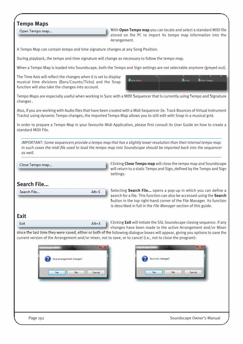
Tempo MapsWith Open Tempomap you can locate and select a standard MIDI filestored on the PC to import its tempo map information into theArrangement.
A Tempo Map can contain tempo and time signature changes at any Song Position.
During playback, the tempo and time signature will change as necessary to follow the tempo map.
When a Tempo Map is loaded into Soundscape, both the Tempo and Sign settings are not selectable anymore (greyed out).
The Time Axis will reflect the changes when it is set to displaymusical time divisions (Bars/Counts/Ticks) and the Snapfunction will also take the changes into account.
Tempo Maps are especially useful when working in Sync with a MIDI Sequencer that is currently using Tempo and Signaturechanges .
Also, if you are working with Audio files that have been created with a Midi Sequencer (ie. Track Bounces of Virtual InstrumentTracks) using dynamic Tempo changes, the imported Tempo Map allows you to still edit with Snap in a musical grid.
In order to prepare a Tempo Map in your favourite Midi Application, please first consult its User Guide on how to create astandard MIDI File.
IMPORTANT: Some sequencers provide a tempo map that has a slightly lower resolution than their internal tempo map.In such cases the midi file used to load the tempo map into Soundscape should be imported back into the sequenceras well.
Clicking Close Tempo map will close the tempo map and Soundscapewill return to a static Tempo and Sign, defined by the Tempo and Signsettings.
Search File...Selecting Search File... opens a pop-up in which you can define asearch for a file. This function can also be accessed using the Searchbutton in the top right-hand corner of the File Manager. Its functionis described in full in the File Manager section of this guide.
ExitClicking Exit will initiate the SSL Soundscape closing sequence. If anychanges have been made to the active Arrangement and/or Mixer
since the last time they were saved, either or both of the following dialogue boxes will appear, giving you options to save thecurrent version of the Arrangement and/or mixer, not to save, or to cancel (i.e., not to close the program):
Page 192 Soundscape Owner’s Manual

TAPE MENUThe Tape menu is divided into four sections:
The items in the top section duplicate the function of the corresponding transport barbuttons.
Clicking on any of the items in the second section of the menu will open a dialogue boxwhere a value can be entered for the corresponding parameter.
The Auto Punch In, Auto Punch Out and Loop modes can be enabled or disabled byclicking the items in the third section of the menu.
The items in the lower section of the menu can be used to arm or disarm all the existingaudio record tracks.
All items are explained in detail in Chapter 4: ‘Arrangement Window.’
IMPORTANT: Certain items in this menu are unavailable in Play mode or Record mode. When this is the case they appeardimmed.
�
Soundscape Owner’s Manual Page 193

EDIT MENUThe Edit menu is divided into four sections. The top section can be used to accessthe Undo/Redo function, the second section can be used to assign the editing toolsto the mouse (left Mouse only, without [ALT] key) , the third section duplicates thetoggle buttons on the bottom right of the Mixer Window (Edit Mode, AutomationEnable, Automatic Delay Compensation and Snapshot), and the fourth section isdedicated to the ‘Zoom’ and ‘Scroll’ functions.
Undo/RedoAny edit that has been made to Parts or Takes can be undone or redone using thisfunction. Up to 99 levels of Undo/Redo are available depending on the valuespecified in the Settings / Preferences / General / Undo/Redo levels menu.
Undo and Redo can also be performed using the [Ctrl]+[Z] and [Ctrl]+[Y] keycombinations respectively.
Saving an Arrangement or closing Soundscape will clear the Undo/Redo Databaseand finalize the Take deletes the user has been confirming during editing.
Editing toolsThe second section of the menu lists the editing tools, and clicking on any item inthis section assigns the corresponding tool to the left mouse button (except for theContext Sensitive Edit tool, which uses both mouse buttons incl. the [ALT] modifierkey). Some of the tools are grouped in submenus according to their function.
All Tools are explained in detail in Chapter 4: ‘Editing Tools’.
Mixer, Automation and Automatic Delay CompensationThe items in this section of the menu duplicate the four buttons in the bottom rightcorner of the Mixer.
These buttons have been described in detail in Chapter 4: ‘Mix Window’.
Zoom and ScrollWhen the mouse pointer is on ‘Zoom’, a submenu with six items appears. Clicking on either of the first two items selects theZoom tool. Clicking the same item a second time will scroll through the memorised ‘view sequence’, as indicated by the‘(1x=rect, 2xprev)’ and ‘(1x=rect, 2xnext)’ mentions. The next four items can be clicked to zoom in or out horizontally orvertically.
When the mouse pointer is on ‘Scroll’, a submenu with four items appears. These items can be clicked to scroll the Arrangewindow horizontally or vertically.
The operation of the Zoom tool, the zoom button, the ‘view sequence/zoom history’ and Scroll functions have been describedin detail in Chapter 4: ‘Arrange Window’: ‘Arrangement Navigation’.
IMPORTANT: Certain items in this menu are unavailable in Play mode or Record mode. When this is the case they appeardimmed.
Page 194 Soundscape Owner’s Manual
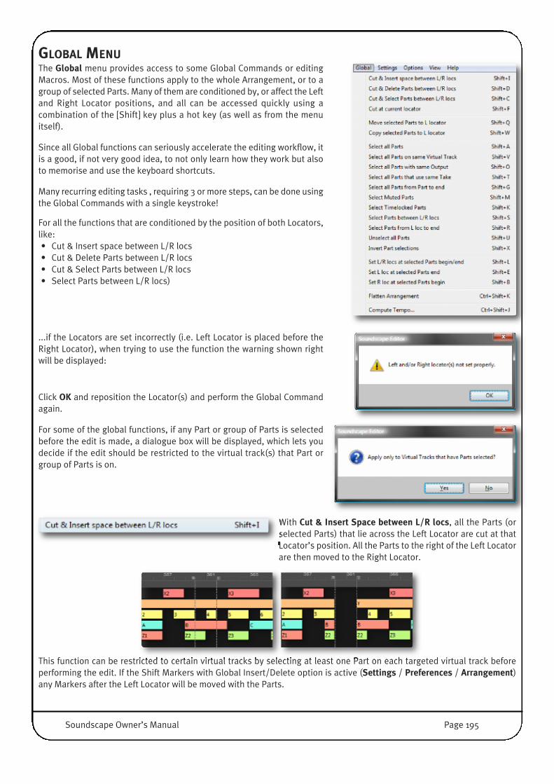
GLOBAL MENUThe Global menu provides access to some Global Commands or editingMacros. Most of these functions apply to the whole Arrangement, or to agroup of selected Parts. Many of them are conditioned by, or affect the Leftand Right Locator positions, and all can be accessed quickly using acombination of the [Shift] key plus a hot key (as well as from the menuitself).
Since all Global functions can seriously accelerate the editing workflow, itis a good, if not very good idea, to not only learn how they work but alsoto memorise and use the keyboard shortcuts.
Many recurring editing tasks , requiring 3 or more steps, can be done usingthe Global Commands with a single keystroke!
For all the functions that are conditioned by the position of both Locators,like:• Cut & Insert space between L/R locs• Cut & Delete Parts between L/R locs• Cut & Select Parts between L/R locs• Select Parts between L/R locs)
...if the Locators are set incorrectly (i.e. Left Locator is placed before theRight Locator), when trying to use the function the warning shown rightwill be displayed:
Click OK and reposition the Locator(s) and perform the Global Commandagain.
For some of the global functions, if any Part or group of Parts is selectedbefore the edit is made, a dialogue box will be displayed, which lets youdecide if the edit should be restricted to the virtual track(s) that Part orgroup of Parts is on.
With Cut & Insert Space between L/R locs, all the Parts (orselected Parts) that lie across the Left Locator are cut at thatLocator’s position. All the Parts to the right of the Left Locatorare then moved to the Right Locator.
This function can be restricted to certain virtual tracks by selecting at least one Part on each targeted virtual track beforeperforming the edit. If the Shift Markers with Global Insert/Delete option is active (Settings / Preferences / Arrangement)any Markers after the Left Locator will be moved with the Parts.
Soundscape Owner’s Manual Page 195

When Cut & Delete Parts between L/R locs is used, a cut ismade to all Parts (or selected Parts) at the Left and Right
Locator positions. The Parts between the Locators are then deleted, and all the Parts to the right of the Right Locator aremoved as a group to the Left Locator, closing up the space created by the edit.
This function can be restricted to certain virtual tracks by selecting at least one Part on each targeted virtual track beforeperforming the edit. If the Shift Markers with Global Insert/Delete option is active (Settings / Preferences / Arrangement)any Markers after the Left Locator will be moved with the Parts.
Cut & Select Parts between L/R locs creates a cut to all Parts(or selected Parts) at the Left and Right
Locator positions. The Parts between the Locators are then selected (ie. to Move/Copy them to a different Track)
This function can be restricted to certain virtual tracks by selecting at least one Part on each targeted virtual track beforeperforming the edit.
When Cut at current locator is used, a cut is made to all Parts(or selected Parts) at the Current Locator position.
This function can be restricted to certain virtual tracks by selecting at least one Part on each targeted virtual track beforeperforming the edit.
When Move selected Parts to L locator is used, any selectedPart(s) are moved to the Left Locator.
Page 196 Soundscape Owner’s Manual
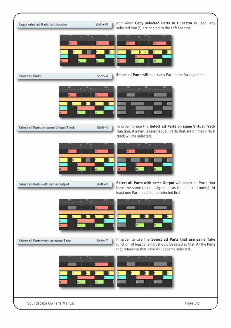
And when Copy selected Parts to L locator is used, anyselected Part(s) are copied to the Left Locator:
Select all Parts will select any Part in the Arrangement.
In order to use the Select all Parts on same Virtual Trackfunction, if a Part is selected, all Parts that are on that virtualtrack will be selected:
Select all Parts with same Output will select all Parts thathave the same track assignment as the selected one(s). Atleast one Part needs to be selected first.
In order to use the Select all Parts that use same Takefunction, at least one Part should be selected first. All the Partsthat reference that Take will become selected.
Soundscape Owner’s Manual Page 197

In order to use the Select all Parts from Part to end function,at least one Part should be selected first. All the Parts that arepositioned to its right, or that have the same beginningposition, will be selected:
�NOTE: This function can also be used by holding [Ctrl]+[Shift] before selecting a Part.
Select Muted Parts will indeed select all the muted Parts.
Select Timelocked Parts will select all timelocked Parts, asidentified by the asterisk (*) appended to their name.
NOTE: Please refer to ‘Timelock tool’ of the ‘Editing Tools’ section for a detailed explanation of timelocked Parts.
Select Parts between L/R locs will select all the Parts of whichany section is positioned between the Locators:
Page 198 Soundscape Owner’s Manual

Select Parts from L loc to end will select all Parts of which anysection is positioned between the Left Locator and the end.
This function can be restricted to certain virtual tracks by selecting at least one Part on each targeted virtual track first.
Unselect all Parts cancels all Part selections.
Invert Part selections deselects all selected Parts andunselected Parts are selected instead.
Set L/R locs at selected Parts begin/end positions the Leftand Right Locators at the beginning and end respectively of
the selected Part or group of Parts. This is especially useful when an area needs to be defined for using the Mixdown tool ora loop is selected to define the Tempo with Compute Tempo function (see next Page).
Set L loc at selected Parts end sets the Left Locator to the endof the selected Part (Part X2 in the example below) or group of
Parts. This is especially useful when an auto punch in point needs to be set precisely set at the end of a Part.
Soundscape Owner’s Manual Page 199

Set R loc at selected Parts begin sets the Right Locator to thebeginning of the selected Part (Part X3 in the example below)
or group of Parts. This is especially useful when an auto punch out point needs to be set precisely at the beginning of a Part.
Flatten Arrangement will remove any overlapped Parts, oroverlapped sections of Parts and crossfades from the
Arrangement . If any Takes become unreferenced as a consequence however, they are not deleted. This is useful for exportingArrangements to certain formats or with export modules where real time crossfades and overlapping parts are not supported.
Compute Tempo calculates the tempo for Soundscape basedon the Left and Right Locator positions, the current TimeSignature and the number of bars being considered.
In the following example, it is used to compute the tempo of a drumPart.
• While the recorded audio Part is played back, drop in the Left andRight Locators on the fly (by pressing the [L] and [R] key) to markthe beginning of bars. In our example, the Locators are dropped two bars apart, but any number of bars can be used.
• Stop Playback and zoom in to a sufficient level and clicking on theLeft and Right Locator buttons in the Transport Bar (blow thereadouts) it is easy to jump between the two marked points.
• It is now possible to place the Left and Right Locators with moreprecision by visual reference to the waveform. The two marked L/Rlocator Positions should look like this.
• Sign in the Transport Bar must match the time signature of the audio (ie. 4/4 for Four on the Floor).
• Click Compute Tempo and enter the number of bars between the Locators in the followingdialogue box.
• Click OK and the tempo is instantly calculated by the software and the value in the Temporeadout is updated accordingly.�
Page 200 Soundscape Owner’s Manual
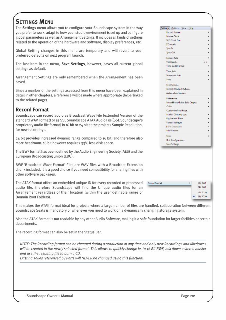
SETTINGS MENUThe Settings menu allows you to configure your Soundscape system in the wayyou prefer to work, adapt to how your studio environment is set up and configureglobal parameters as well as Arrangement Settings. It includes all kinds of settingsrelated to the operation of the hardware and software, display preferences, etc.
Global Setting changes in this menu are temporary and will revert to yourpreferred defaults on next program launch.
The last item in the menu, Save Settings, however, saves all current globalsettings as default.
Arrangement Settings are only remembered when the Arrangement has beensaved.
Since a number of the settings accessed from this menu have been explained indetail in other chapters, a reference will be made where appropriate (hyperlinkedto the related page).
Record FormatSoundscape can record audio as Broadcast Wave File (extended Version of thestandard WAV Format) or as SSL Soundscape ATAK Audio File (SSL Soundscape'sproprietary audio file format) in 16 bit or 24 bit at the projects Sample Resolution,for new recordings.
24 bit provides increased dynamic range compared to 16 bit, and therefore alsomore headroom. 16 bit however requires 33% less disk space.
The BWF format has been defined by the Audio Engineering Society (AES) and theEuropean Broadcasting union (EBU).
BWF ‘Broadcast Wave Format’ files are WAV files with a Broadcast Extensionchunk included. It is a good choice if you need compatibility for sharing files withother software packages.
The ATAK format offers an embedded unique ID for every recorded or processedaudio file, therefore Soundscape will find the Unique audio files for anArrangement regardless of their location (within the user definable range ofDomain Root Folders).
This makes the ATAK format ideal for projects where a large number of files are handled, collaboration between differentSoundscape Seats is mandatory or whenever you need to work on a dynamically changing storage system.
Also the ATAK Format is not readable by any other Audio Software, making it a safe foundation for larger facilities or certaindepartments.
The recording format can also be set in the Status Bar.
NOTE: The Recording format can be changed during a production at any time and only new Recordings and Mixdownswill be created in the newly selected format. This allows to quickly change ie. to 16 Bit BWF, mix down a stereo masterand use the resulting file to burn a CD.Existing Takes referenced by Parts will NEVER be changed using this function!
Soundscape Owner’s Manual Page 201
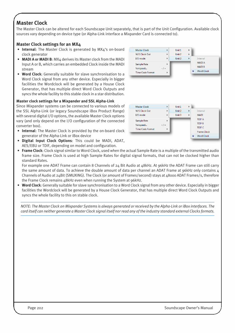
Master ClockThe Master Clock can be altered for each Soundscape Unit separately, that is part of the Unit Configuration. Available clocksources vary depending on device type (or Alpha-Link interface a Mixpander Card is connected to).
Master Clock settings for an MX4• Internal: The Master Clock is generated by MX4‘s on-board
clock generator• MADI A or MADI B: MX4 derives its Master clock from the MADI
Input A or B, which carries an embedded Clock inside the MADIstream
• Word Clock: Generally suitable for slave synchronisation to aWord Clock signal from any other device. Especially in biggerfacilities the Wordclock will be generated by a House ClockGenerator, that has multiple direct Word Clock Outputs andsyncs the whole facility to this stable clock in a star distribution.
Master clock settings for a Mixpander and SSL Alpha-LinkSince Mixpander systems can be connected to various models ofthe SSL Alpha-Link (or legacy Soundscape iBox Product Range)with several digital I/O options, the available Master Clock optionsvary (and only depend on the I/O configuration of the connectedconverter box).• Internal: The Master Clock is provided by the on-board clock
generator of the Alpha-Link or iBox device• Digital Input Clock Options: This could be MADI, ADAT,
AES/EBU or TDIF, depending on model and configuration.• Frame Clock: Clock signal similar to Word Clock, used when the actual Sample Rate is a multiple of the transmitted audio
frame size. Frame Clock is used at high Sample Rates for digital signal formats, that can not be clocked higher thanstandard Rates. For example one ADAT Frame can contain 8 Channels of 24 Bit Audio at 48kHz. At 96kHz the ADAT Frame can still carrythe same amount of data. To achieve the double amount of data per channel an ADAT Frame at 96kHz only contains 4Channels of Audio at 24Bit (SMUXING). The Clock (or amount of Frames/second) stays at 48000 ADAT Frames/s, thereforethe Frame Clock remains 48kHz even when running the System at 96kHz.
• Word Clock: Generally suitable for slave synchronisation to a Word Clock signal from any other device. Especially in biggerfacilities the Wordclock will be generated by a House Clock Generator, that has multiple direct Word Clock Outputs andsyncs the whole facility to this on stable clock.
NOTE: The Master Clock on Mixpander Systems is always generated or received by the Alpha-Link or iBox interfaces. Thecard itself can neither generate a Master Clock signal itself nor read any of the industry standard external Clocks formats.
Page 202 Soundscape Owner’s Manual

Master clock settings for a Mixpander connected to Soundscape 32 unit• Internal: When this option is selected, the Sample Rate is
set by the Soundscape unit’s on board Master ClockGenerator. This should be used in conjunction withanalogue equipment only.
• AES/EBU (S/PDIF): When this option is selected theSoundscape 32 is slaved to the WordClock signal receivedat its AES/EBU (S/PDIF) input.
• TDIF A, TDIF B, TDIF C: When one of these options isselected Soundscape 32 operates as WordClock Slave tothe source device connected to the corresponding TDIFport.
• Super Clock + TDIF A, Super Clock + TDIF B, Super Clock+ TDIF C: These options operate in a similar manner to the TDIF A, TDIF B, and TDIF C options described above, except thata SuperClock signal at 256 times the Sample Rate is used to provide the higher frequency system clock for Soundscape32, with the LRClk signal providing the WordClock reference.
• Super Clock: If this setting is selected, it is assumed that Soundscape 32’s internal clock divider produces the samplefrequency Word Clock derived from the incoming Super Clock and that other devices are slaved to Soundscape 32 via theWord Clock, TDIF, or AES/EBU (S/PDIF) outputs. Super Clock is a higher frequency clock signal (256 x Sample Rate).
• Word Clock: When this option is selected Soundscape 32 is slaved to the WordClock signal received at its WordClockinput connector.
• Word Clock + 90/180/270 deg phase: These variants of the ‘WordClock’ setting are provided to adapt to different TDIFimplementations as found in other devices, such as, for example, the Mackie D8B digital mixing console.
• Video Sync: This option is only available when the optional Soundscape Synchronization Board is installed in theSoundscape 32 unit (Unit 1 in a multiple unit system). If it is selected Soundscape 32 can be slaved to any VideoSynchronisation signal such as Blackburst or Composite received via the VITC Input of Synchronisation Board.
Soundscape Owner’s Manual Page 203
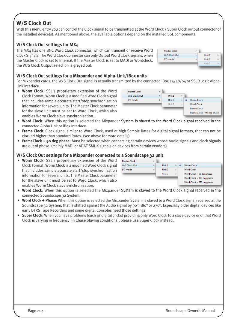
W/S Clock OutWith this menu entry you can control the Clock signal to be transmitted at the Word Clock / Super Clock output connector ofthe installed device(s). As mentioned above, the available options depend on the installed SSL components.
W/S Clock Out settings for MX4�The MX4 has one BNC Word Clock connector, which can transmit or receive WordClock Signals. The Word Clock Connector can only Output Word Clock signals, whenthe Master Clock is set to Internal. If the Master Clock is set to MADI or Wordclock,the W/S Clock Output selection is greyed out.
W/S Clock Out settings for a Mixpander and Alpha-Link/iBox unitsFor Mixpander cards, the W/S Clock Out signal is actually transmitted by the connected iBox 24/48/64 or SSL XLogic Alpha-Link interface.• Worm Clock: SSL‘s proprietary extension of the Word
Clock Format. Worm Clock is a modified Word Clock signalthat includes sample accurate start/stop synchronisationinformation for several units. The Master Clock parameterfor the slave unit must be set to Word Clock, which alsoenables Worm Clock slave synchronisation.
• Word Clock: When this option is selected the Mixpander System is slaved to the Word Clock signal received in theconnected Alpha Link or iBox Interface.
• Frame Clock: Clock signal similar to Word Clock, used at high Sample Rates for digital signal formats, that can not beclocked higher than standard Rates. (see above for more details)
• FrameClock + 90 deg phase: Must be selected when connecting certain devices whose Audio signals and clock signalsare out of phase. (mainly MADI or ADAT SMUX signals on devices from certain vendors)
W/S Clock Out settings for a Mixpander connected to a Soundscape 32 unit• Worm Clock: SSL‘s proprietary extension of the Word
Clock Format. Worm Clock is a modified Word Clock signalthat includes sample accurate start/stop synchronisationinformation for several units. The Master Clock parameterfor the slave unit must be set to Word Clock, which alsoenables Worm Clock slave synchronisation.
• Word Clock: When this option is selected the Mixpander System is slaved to the Word Clock signal received in theconnected Soundscape 32 System.
• Word Clock + Phase: When this option is selected the Mixpander System is slaved to a Word Clock signal received at theSoundscape 32 System, that is shifted against the Audio signal by 90°, 180° or 270°. Especially older digital devices likeearly DTRS Tape Recorders and some digital Consoles need those settings.
• Super Clock: When you have problems (such as digital clicks) providing only Word Clock to a slave device or of that WordClock is varying in frequency (in Chase Slaving conditions), please use Super Clock instead.
Page 204 Soundscape Owner’s Manual

I/O modeI/O Mode covers all hardware specific settings that define the I/O format configuration. This includes I/O Modes for operationat high Sample Rates and the general Settings for MADI Communication. Again, the available options are determined by theSSL Hardware you are using.
64-96kHz�Allows selection of different I/O configurationsand interleaving options at high sample rates,such as SMUXed or non-SMUXed Modes forADAT/TDIF/MADI/AES or different I/Ocombinations for a Soundscape 32/Mixpandersystem.
MADI 64-96kHz�In this submenu the MADI Frame Pattern isselected between 96k Legacy Pattern (48K Frame)and 96k Frame Pattern.
The options determine how the 28/32 MADIChannels are encoded inside one MADI Frame.
MADIThis submenu selects the MADI CH Mode (56 or64 Channels). In its early days (last Millennium)MADI had 56 CH (at 44.1kHz and 48kHz) and somedata band-width headroom to enable ‘Vari-Speed’ on all Channels at a higher play speed(=higher Sample Rate).
Since providing the facility for Vari-Speed is notnecessary in many environments, the 64 CH MADIMode was introduced as an AES standard, whichuses the full MADI data bandwidth, hence doesn‘tallow a higher sample rate (or Vari-Speed withpositive Values).
Both standards are equally popular, dependingon the variety of applications and industries youwork in, you may need to switch between thesemodes quite often. At 88.2 kHz and 96 kHz a 56CH MADI cable operates with 28Ch of audio, whilewith 64 CH MADI, 32 Channels of audio aretransmitted.
Soundscape Owner’s Manual Page 205

SynchronisationSync In defines whether Soundscape responds to external Midi Time Code, and Sync Out allows MTC to be sent fromSoundscape. Sync configuration is performed in the Settings / Sync Setup window.
Sync In�• Off [M]: Clicking this option or pressing [M] will select it. When Off is
selected, Soundscape does not respond to incoming Time Code.• MTC [S]: Clicking this option or pressing [S] will select it. In MTC Slave
mode Soundscape 32 responds to MIDI Time Code received at its MIDIIn port.
NOTE: Soundscape will only respond to incoming MTC if it is in Play mode or Record mode, i.e., if the Play or Recordbutton has been clicked, or if the Auto Play/Stop when slave syncing option is selected under Settings / Sync Setup.
Sync Out• MTC: This setting should be selected (by clicking on it or pressing the [M] key on the computer keyboard) to use SSL
Soundscape as a MIDI Time Code Master, with one or more Time Code Slave devices synchronised to the MIDI Time Codesent via the MIDI Out port.
Legacy Soundscape 32 Synchronisation This section describes the synchronisation functionality of a legacy Soundscape 32 Unit connected to a PCI Host IF Card andconfigured as Unit1. Using a Soundscape 32 Unit bi-directional Sync to external devices as MTC Master, MIDI Clock Master,MTC Chase Slave or MTC Trigger Slave using its MIDI In and MIDI Out connectors is possible. Soundscape 32 can also lockto incoming LTC, VITC or 9-Pin Time Code, and output LTC and BITC, providing an integrated solution suitable for mostsynchronisation tasks in Music, Post and Broadcast. Since the Soundscape 32 Hardware can output several types of TimeCode simultaneously while chase slaving to incoming Time Code, it can even act as a Time Code converter.
Additional Sync In options• LTC [O]: Clicking this option or pressing [O] will select it. In LTC Slave mode Soundscape 32 respond to Longitudinal Time
Code received via the LTC In port on the optional Soundscape Synchronisation Board (RCA/Cinch connector). If theSoundscape Synchronisation Board is not present the LTC option appears dimmed.
NOTE: Soundscape will only respond to incoming LTC if it is in Play mode or Record mode, i.e., if the Play or Recordbutton has been clicked, or if the Auto Play/Stop when slave syncing option is selected under Settings / Sync Setup.
• VITC: Clicking this option will select it. In VITC Slave mode Soundscape 32 respond to Vertical Interval Time Code receivedvia the VITC In port on the optional Soundscape Synchronization Board (BNC connector). If the SoundscapeSynchronization Board is not present the VITC option is not available and appears dimmed.
NOTE: Soundscape will only respond to incoming VITC if it is in Play mode or Record mode, i.e., if the Play or Recordbutton has been clicked, or if the Auto Play/Stop when slave syncing option is selected under Settings / Sync Setup.
• 9-Pin: This option is available when SSL Soundscape is set to Controller, Synchro or Layback under menu: Settings / 9-Pin Operation / Mode. Clicking it will select it. In 9-Pin Time Code mode Soundscape 32 respond to 9-Pin Time Codereceived via the 9-Pin connector on the optional Soundscape Synchronization Board. If the SSL SoundscapeSynchronization Board is not present the 9-Pin option is not available and appears dimmed.
NOTE: Soundscape will only respond to incoming 9-Pin Time Code if it is in Play mode or Record mode, i.e., if the Playor Record button has been clicked, or if the Auto Play/Stop when slave syncing option is selected under Settings / SyncSetup.
Page 206 Soundscape Owner’s Manual

• Chase: This setting should be selected (by clicking on it or pressing the [S] key on the computer keyboard) to use SSLSoundscape as a Time Code Chase Slave. In this case, Soundscape will wait for incoming Time Code, and lock to thatTime Code within about 1.5s (please also read the Sync Setup section of this chapter regarding the Sync In ‘PreparationTime’).
NOTE: Soundscape will only respond to incoming Time Code if it is in Play mode or Record mode, i.e., if the Play orRecord button has been clicked, or if the Auto Play/Stop when slave syncing option is selected under Settings / SyncSetup.
Soundscape 32 implements a full ‘Chase Lock’, which means that it continuously monitors the incoming Time Code, andif that time code presents fluctuations, Soundscape 32 will vary its sample rate to maintain optimum synchronization. Thisis essential if synchronizing to a tape machine that has Time Code recorded on one track, as the tape speed can vary and,without Chase Lock, significant timing errors would occur. Soundscape will also follow large changes in timing whichoccur when using varispeed, etc.
IMPORTANT:In Chase Slave mode, Soundscape's Sample Rate Master Clock is varied to adapt to any fluctuation of the incoming TimeCode. Therefore it is only possible to record or play back via the digital I/O if the devices that are connected to the digitalI/O are slaved to Soundscape 32’s Master Clock.If you are RECORDING audio such as LIVE musical performances while ‘CHASING’ a tape machine or other source thatmay produce large changes in Time Code, you are likely to hear pitch changes on playback when using a stable TimeCode source (e.g., MIDI sequencer) or SSL Soundscape’s own internal clock.
• Trigger: When Time Code Trigger Slave mode is selected, the received Time Code only indicates the start and stoplocations and the Sample Rate used can either be internal, or received from a digital input as required. This means thatwhen the Time Code Master is an external digital device which provides both a Time Code signal and a digital audio signal(such as a multitrack digital tape recorder that transmits MTC), full lock-up is provided by the digital input signal onceplayback or recording has been triggered via the Time Code.
NOTE: Soundscape will only respond to incoming Time Code if it is in Play mode or Record mode, i.e., if the Play orRecord button has been clicked, or if the Auto Play/Stop when slave syncing option is selected under Settings / SyncSetup.
Additional Sync Out Options• LTC: This setting should be selected to use SSL Soundscape as an LTC Master, with one or more LTC Slave devices
synchronised to the Longitudinal Time Code sent via the LTC Out port (RCA/Cinch connector) on the optional Sync Option.(otherwise the LTC option is not available and appears dimmed)
• BITC: This setting should be selected to add Burnt-In Time Code to a video signal received via the VITC input on theoptional Sync Option (otherwise this option is not available and appears dimmed). The original video signal needs to befed into the VITC Input (as composite PAL/NTSC Video) and will then be sent with the added Burnt-In Time Code to theVITC output (as a composite PAL/NTSC signal).
• Midi Clock: This setting should be selected to use Soundscape as a MIDI Clock Master unit, with one or more Slave devicessynchronised to the MIDI Clock and Song Position Pointer messages which are sent via the MIDI Out port whenSoundscape is in Play mode or Record mode. The MIDI Clock timing depends on Soundscape’s Tempo setting.
NOTE: The MIDI Clock option is not available when a tempo map is loaded, as described in ‘Tempo maps’ in the ‘FileMenu’ section of this chapter.
Soundscape Owner’s Manual Page 207

Sample RateThe Sample Rate submenu lists all available clock speeds when the Unit isinternally clocked. This menu appears dimmed and cannot be used if the SSLDevice (or devices) are clocked to an external device.
Internal Sample Rates• 22.500Hz (Multimedia)• 32.000Hz (Video and Broadcast Standard)• 44.056Hz (NTSC Drop Frame Pull Down of 44.1kHz)• 44.100Hz (CD Standard)• 47.952Hz (NTSC Drop Frame Pull Down of 48kHz)• 48.000Hz (Broadcast Standard)• 64.000Hz (Video)• 88.112Hz (HD NTSC Drop Frame Pull Down of 88.2kHz)• 88.200Hz (High Definition Audio)• 95.904Hz (NTSC Drop Frame Pull Down of 96kHz)• 96.000Hz (High Definition Audio and Video)
The Sample Rate is also displayed and can be set in the Status Bar, unless an external Master Clock source is selected.
The Sample Rate is shown in red in the Status Bar when Varispeed is active(please read below).
VarispeedThe Varispeed setting provides a +/-10% variation in the Sample Rate. Clicking Varispeedopens the Varispeed dialogue where the required value can be entered (as a percentage):
The Varispeed setting can also be adjusted by using the [�] and [+] keys (from the main keyarea of the computer keyboard only, not from the numeric keypad), which change thevarispeed value in �0.1% or +0.1% increments, respectively.
The Varispeed setting is saved with the Arrangement.
IMPORTANT: Varispeed can be active in RECORD mode. Therefore, if you save an Arrangement with a non-zero Varispeedsetting, subsequent recordings within this Arrangement will be made at a non-standard Sample Rate! If the Varispeedvalue is not 0.00%, the Sample Rate will be shown in RED in the Status Bar. DAT machines and other digital devices maynot be able to lock onto the Master Clock signal supplied via Soundscape’s audio outputs when varispeed is used.
Page 208 Soundscape Owner’s Manual
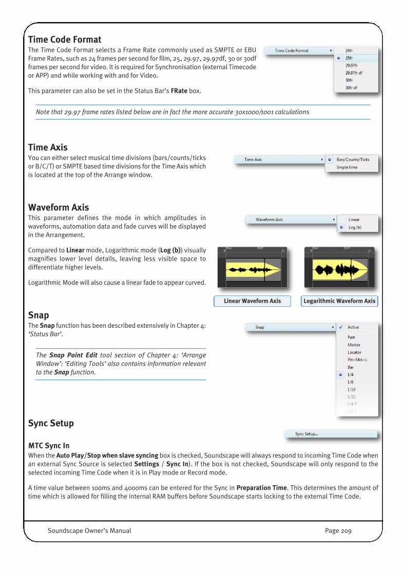
Time Code FormatThe Time Code Format selects a Frame Rate commonly used as SMPTE or EBUFrame Rates, such as 24 frames per second for film, 25, 29.97, 29.97df, 30 or 30dfframes per second for video. It is required for Synchronisation (external Timecodeor APP) and while working with and for Video.
This parameter can also be set in the Status Bar’s FRate box.
Note that 29.97 frame rates listed below are in fact the more accurate 30x1000/1001 calculations
Time AxisYou can either select musical time divisions (bars/counts/ticksor B/C/T) or SMPTE based time divisions for the Time Axis whichis located at the top of the Arrange window.
Waveform AxisThis parameter defines the mode in which amplitudes inwaveforms, automation data and fade curves will be displayedin the Arrangement.
Compared to Linear mode, Logarithmic mode (Log (b)) visuallymagnifies lower level details, leaving less visible space todifferentiate higher levels.
Logarithmic Mode will also cause a linear fade to appear curved.
SnapThe Snap function has been described extensively in Chapter 4:‘Status Bar’.
The Snap Point Edit tool section of Chapter 4: ‘ArrangeWindow’: ‘Editing Tools’ also contains information relevantto the Snap function.
Sync Setup
MTC Sync InWhen the Auto Play/Stop when slave syncing box is checked, Soundscape will always respond to incoming Time Code whenan external Sync Source is selected Settings / Sync In). If the box is not checked, Soundscape will only respond to theselected incoming Time Code when it is in Play mode or Record mode.
A time value between 100ms and 4000ms can be entered for the Sync in Preparation Time. This determines the amount oftime which is allowed for filling the internal RAM buffers before Soundscape starts locking to the external Time Code.
Linear Waveform Axis Logarithmic Waveform Axis
Soundscape Owner’s Manual Page 209

The default is 1500ms. It may be possible to reduce this lock time if required, depending on the number of active tracks inthe Arrangement and the Disk and overall PC performance.
Please also read the Recording while slaving to Time Code subsection of Chapter 4, especially if you need to record from thebeginning of an Arrangement while Soundscape is slaved to external Time Code.
A time value up to 21768ms can be entered for the Drop Out Time. When Soundscape is slaved to incoming Time Code, thisdetermines how long it will remain in Play mode after the master device has ceased sending proper Time Code or has beenstopped. Entering 0 sets the drop out time to infinite. Since Soundscape can not differentiate between Time Code ‘Drop Outs’and no Time Code at all (e.g. if the Master stops) this free-wheeling time should be set as low as possible.
You can introduce an offset into the incoming time code using the Incomingtime code offset: box.
It is also possible to enable MMC (Midi Machine Control) Transport SlaveOperation, in order to control Soundscape's Transport remotely from aSequencer or Hardware surface which supports MMC. To do this, check theEnable MMC slave operation box, then define the remote device’s MMCDevice ID and the Midi Port being used.
MTC Sync OutIn the MTC Sync Out section, the Midi Port on which MTC is transmitted fromSoundscape can be defined.
Once you have completed your Sync Setup, click OK to save and close thedisplay, or Cancel to close the display without saving.
Legacy Soundscape 32 Sync OptionsIf you are running a SS32 system, further options will be available in the SyncSetup window:
Two radio buttons allow you to select how MTC should be decoded at MIDITime Code frame boundaries. The first option is fully compatible with the MIDIspecification, while the second option should be selected when loadingprojects started in earlier versions of Soundscape.
VITC Sync InIn the VITC Sync In section, the Format box can be used to select a VITCformat. The Line and Field settings determine the location in the video signalof the VITC information used to decode the VITC data. If the data in theprimary location is corrupt, the secondary location is checked. Clicking thearrow to the right of a box opens the list of different value that can beselected.
BITC Sync OutIn the BITC Sync Out section, the on-screen position of the Burnt In Time Codedisplay can be selected.
Page 210 Soundscape Owner’s Manual

Record/Playback SetupClick to open the Record Setup dialogue box.
Record Pre/Post RollThe preroll and postroll options can be activated and Pre/Post Roll values can be entered either in SMPTE time or in Bars /Counts / Ticks.
Maximum record time per Track for manual punch out You can enter a max. time in SMPTE time or in bars/counts/ticks in the middlesection of the window after which Soundscape will drop out of Record modeautomatically.
The setting must be ‘0’ if you want to use as much contiguous space as isavailable on the target drive.
Limiting the potential recording time can improve Disk Performance, sinceSoundscape will create an empty file for each Recording Track in the set lengthat the beginning of the recording, potentially decreasing random seek timesof the drives due to predictable data locations.
Record Auto Stop• If At auto punch out point (if no loop recording) is checked, Soundscape will
automatically stop upon reaching the Right Locator (or the end of thepostroll if active) when recording with Auto Punch Out.
• If At end of recording loop stack (if loop recording) is checked, Soundscapewill automatically stop upon reaching the Right Locator (or the end of thepostroll if active) after the last Take in a record loop stack has beenrecorded. If several record loop stacks are running concurrently, ‘Auto stop’happens at the end of the Stack with the highest Track count.
In the bottom section of the window, checking or unchecking the first box will respectively enable or disable the Allow trackarm changes during record w/gapless punch-out option. When enabled:
• The track arming buttons can be used in Record mode to perform punch ins and punch outs for individual tracks (thecorresponding key commands can be used as well)
• When punching out on audio tracks, the audio after the punch out point is played back immediately, virtually previewingan overdub immediately (à la Tape). The record tracks use double Disk and Buffer bandwidth to provide the gapless punchouts, since Soundscape needs to record a new signal and play back (muted until punching out) the underlying existingTracks simultaneously.
If the Seamless loop during record/playback, if looping is active box is checked, audio is played continuously when theCurrent Locator jumps from the Right Locator to the Left Locator in Loop mode. If the box is not checked, there is a gap in theaudio.
• Seamless looping is ideal for certain tasks, such as practising an instrumental part over a repetitive loop. However, pleasenote that the SSL Soundscape external Time Code Generator does not follow the loop. If it did, the behaviour of a TimeCode Slave device (e.g., an external Mixing Console with Time Code based automation) would be erratic, since this devicewould in effect receive ‘jumping’ Time Code.
• Seamless Looping as an ASIO Positioning protocol Master, however, works in combination with most APP awareapplications, if the slaving Sequencer (ie. Nuendo/Cubase) is also in Loop Playback, set to the same Loop I/O locations.
Soundscape Owner’s Manual Page 211

Page 212 Soundscape Owner’s Manual
Automation SetupThe Automation Setup entry opens the Automation Setup window. Allsettings in that window have been described in detail in Chapter 4: ‘MixerAutomation’. Please refer to that section for details.
PreferencesThe Preferences section provides access to various settings affecting thegeneral behaviour of the software and the way it interacts with hardware.
Five submenus help to organise all available options.
General preferencesWhen Deglitch is active, each time the Current Locator crosses a Partboundary, Soundscape performs an automatic glitch removal
algorithm. This removes the nasty clicks that are sometimes generated when editing digital audio and the amplitude of thewaveform did not match a zero crossing (=silence) at the Part boundary.
This function effectively removes any need to think about precisely where you cut audio in Soundscape or the necessity toadd tiny crossfades to any edit afterwards.
The Deglitch algorithm creates very small fades for you automatically and they are only as long, as they need to be (to avoidclicks).
Soundscape detects audio material that is continuous across a cut (e.g., when a cut has been made in order to fade a sectionof a Part), and does not perform a deglitch in this case.
When the Auto generate waveform files option is selected, as soon asa new audio Take is created (by recording or processing), acorresponding waveform file is generated automatically.
When the Keep all generated waveform files option is selected, anywaveform files that have been generated are saved on the PC’s hard
disk upon exiting Soundscape. Otherwise, only the waveform files for Takes that are still on the Domain Folders will be savedand all others will be deleted from the PC’s hard disk.
When the Play till next Marker option is selected, Soundscape stopsplayback at each Marker. This is useful for ‘previewing’ edits, or when
‘cueing’ up audio for radio spots or theatre. Putting a Marker at the beginning of each audio segment defines ‘cue points’.When playback is triggered, it carries on ‘till the next Marker’ is reached, stopped at the next ‘cue point’, ready for the nexttrigger.
When the Fast REW / FF option is selected, rewinding and fastforwarding are performed at four times the default speed. This setting
has no effect if the Scrub during REW / FF option described below is also enabled.
When the Scrub during REW / FF option is selected (ticked), audio isplayed during rewind and fast forward operations. Reverse Play can
also be performed at normal playback speed. Please read Chapter 4: ‘Tape Transport Bar’ for further details.

Soundscape Owner’s Manual Page 213
When the Ignore incoming samplerate indication option is selected,if the Master Clock source for a Soundscape 32 unit is set to AES/EBU
(S/PDIF) or TDIF, the incoming AES/EBU or TDIF Sample Rate indication is ignored, and the current Sample Rate is maintained.This is useful if the Master Clock source being used transmits an incorrect Sample Rate indication.
When Auto append DATE-TIME... is selected, recorded
Takes get the current date and time appended to the end of their name inYear/Month/Day – Hour/Minute/Second format.
Clicking Undo/Redo levelsopens a dialogue box where
any value between 1 and 99 can be entered to determine the number of availableUndo/Redo levels.
Undo and Redo commands are found in the Editmenu. Standard [Ctrl]+[Z] and [Ctrl]+[Y] commands can also be used.
The Auto Save time functionbacks up the current
Arrangement and Mixer files automatically and periodically according to a user-defined time interval. This Files are saved in the Record/Process folder marked forthe currently open Arrangement.
Clicking Auto Save time calls up a dialogue box where the required time interval can be entered. The interval must be enteredin minutes and any value between 0 (Auto Save off) and 60 can be entered.
When multichannel audio is recorded as a 4 channel,6 channel or 8 channel record block, imported ormodified, an extension is appended to the Part name.
The Multi-Channel speaker name extension option can add a Numeric extension to the name of each recorded file: 1_x, 2_x,3_x…, where x is the number of multi-channel linked tracks. If Surround is selected, the extensions are: L, R, C, Cs for 4 channels, L, R, C, LFE, Ls, Rs for 6 channels or L, R, C, LFE, Ls, Rs,Lc, Rc for 8 channels.
The SS32 Midi Port Setup submenu only showsselectable entries for legacy Soundscape 32hardware units.
Clicking on the Unit Entry opens a simple dialogue, shown right. If MIDI In Merge isactivated (box checked), Soundscape mixes the MIDI messages received at its MIDIinput with the Time Code generated internally, and sends the combined data to itsMIDI Output. All MIDI messages are merged, except for MIDI ‘Real-Time’ messages.
A MIDI sequencer could therefore be synchronised to MIDI Time Code or to MIDI Clock and Song Position Pointers generatedby Soundscape 32, while MIDI performance data is sent to the sequencer for recording, from a master keyboard viaSoundscape 32's Midi Input.
If a sequencer receives a Time Code signal from Soundscape via MIDI while this sequencer also has a MIDI output connectedto Soundscape’s MIDI input, a MIDI loop is created. In this case the MIDI In Merge function should be disabled (boxunchecked).

When the mouse pointer is on AES/EBU (S/PDIF)Xmt Channel Status, a submenu appears which letsyou select Consumer or Professional format for the
digital audio data transmitted from a Soundscape 32’s AES/EBU (S/PDIF) outputs.
Changing this setting may be necessary due to the limitations of other devices. For example, some professional DAT recorderswill not record from their digital inputs if they receive data in the ‘Consumer’ format. SSL Soundscape adjusts to either formatautomatically, therefore there is no equivalent setting for the AES/EBU (S/PDIF) digital input.
Arrangement PreferencesThe Arrangement Preferences centralise all options for the visual andlogical behaviour of the Arrangement Window. The default settings arechosen carefully. However, when you are experienced with Soundscape,you may want to optimise certain settings for your personal workflow.
While by default the Current Locator moves in theArrange window according to the current time position,
if the Auto scroll option is selected, the Current Locator becomes fixed in the middle of the Arrange window, and theArrangement itself (i.e., the Parts, Time Axis, and Marker Bar) scrolls in the relevant direction when Soundscape is in Play,Record, Rewind, or Fast Forward mode.
This feature requires a reasonably powerful PC with a fast graphics card, otherwise the movement will be jerky. Thesmoothness of the scrolling may also be affected by the number of tracks that display waveforms. With Fill Waveform turnedoff (described below), the waveform display will be redrawn faster when scrolling.
Selecting Fast Redraw will send the waveform displaygraphics of each Track directly to the graphics
accelerator card. Depending on the speed of the PC and card, this can result in constant, partial screen updates, creating theimpression of a ‘nervous’ screen. When this option is off, the whole screen is updated from memory when necessary, requiringa less powerful graphics card, and in many cases creating a ‘smoother’ screen redraw.
When Fill waveform is selected, waveforms aredisplayed as solid black. Otherwise they are displayedas outlines, which can speed up redraws:
When the Show Part name in waveform option isselected, the name of each Part that displays a
waveform or automation data is shown. Audio Parts that do not display a waveform do not respond to this setting, as theirname is displayed anyway. Waveform based editing may be easier if the Part name is not shown in the waveform.
Page 214 Soundscape Owner’s Manual

When the Show Part volume option is selected, thevolume of each audio Part is represented by the height
of the Part’s coloured section. If this option is disabled, the volume is still shown for any selected Part(s) or when certain tools(e.g., the Volume Trim tool) are used.
When the Keep Part selection option is active, Partsremain selected after they have been edited or
processed. This is particularly useful when several editing and/or processing operations must be performed on a group ofParts, and re-selecting these Parts prior to each operation would involve zooming in or out or scrolling repeatedly.
The active/inactive status of the Shift Markers withGlobal Insert/Delete function determines whether any
existing Markers will be automatically moved to reflect changes to the Arrangement layout caused by a global ‘Cut & Insert’or ‘Cut & Delete’ operation.
When Auto Samplerate Convert... is enabled and aTake is dragged from the File Manager to the Arrange
window, the sample rate is converted if necessary to match that of the Arrangement.
IMPORTANT: As for all Audio Processing tools the source audio Take(s) may be deleted automatically, depending onthe setting of the Audio Processing tools behaviour (described in this section below).
If Adopt virtual track Output assignment... is active,any record track inserted in a virtual track slot of the
Record Track Column also determines a default output assignment (physical track) for the corresponding virtual track. AnyPart moved or copied to a virtual track that has an output assignment is automatically assigned to the corresponding physicaltrack. Parts dragged from File Manager will also adopt the Track assignment of the virtual Track they are dropped on.
The group of Parts in the example to the right is beingmoved down by three virtual tracks using the MoveVertical tool, with ‘Adopt virtual track...’ active.
• Audio Part A has been moved from track 3 to track 10Audio Part B ends up on a virtual track that does nothave an output assignment therefore it remainsassigned to track 5. Audio Parts C and D (stereo linked, originally assignedto tracks 9-10) have been assigned to tracks 15-16.
• Track assignments for moved stereo linked Parts willonly be changed if both destination virtual tracks havean output assignment. (even if they are mono Trackswith non consecutive numbers).
• Part E moves to a virtual track assigned to output track29, but remains muted.
• Part F (originally assigned to track 29) has been assigned to track 20• Automation Part Autom F… (originally assigned to automation track 29) has been assigned to automation track 40.
Soundscape Owner’s Manual Page 215
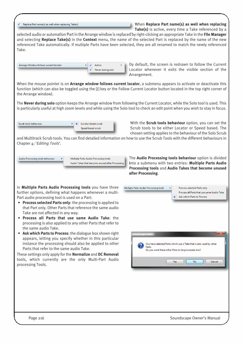
When Replace Part name(s) as well when replacingTake(s) is active, every time a Take referenced by a
selected audio or automation Part in the Arrange window is replaced by right-clicking an appropriate Take in the File Managerand selecting Replace Take(s) in the Context menu, the name of the selected Part is replaced by the name of the newreferenced Take automatically. If multiple Parts have been selected, they are all renamed to match the newly referencedTake.
By default, the screen is redrawn to follow the CurrentLocator whenever it exits the visible section of theArrangement.
When the mouse pointer is on Arrange window follows current locator, a submenu appears to activate or deactivate thisfunction (which can also be toggled using the [J] key or the Follow Current Locator button located in the top right corner ofthe Arrange window).
The Never during solo option keeps the Arrange window from following the Current Locator, while the Solo tool is used. Thisis particularly useful at high zoom levels and while using the Solo tool to check an edit point when you wish to stay in focus.
With the Scrub tools behaviour option, you can set theScrub tools to be either Locator or Speed based. Thechosen setting applies to the behaviour of the Solo Scrub
and Multitrack Scrub tools. You can find detailed information on how to use the Scrub Tools with the different behaviours inChapter 4: ‘Editing Tools’.
The Audio Processing tools behaviour option is dividedinto a submenu with two entries: Multiple Parts AudioProcessing tools and Audio Takes that become unusedafter Processing.
In Multiple Parts Audio Processing tools you have threefurther options, defining what happens whenever a multi-Part audio processing tool is used on a Part:• Process selected Parts only: the processing is applied to
that Part only. Other Parts that reference the same audioTake are not affected in any way.
• Process all Parts that use same Audio Take: theprocessing is also applied to any other Parts that refer tothe same audio Take.
• Ask which Parts to Process: the dialogue box shown rightappears, letting you specify whether in this particularinstance the processing should also be applied to otherParts that refer to the same audio Take.
These settings only apply for the Normalize and DC Removaltools, which currently are the only Multi-Part Audioprocessing Tools.
Page 216 Soundscape Owner’s Manual

In Audio Takes that become unused after Processing you againhave three options defining what happens whenever an audioTake becomes unused after an audio Part has been processed:
• Always delete: it is deleted automatically without notice.• Never delete: no action is taken. The Take remains on disk.� • Ask to delete: the dialogue box shown right appears, letting
you specify whether in this particular instance the unused(unreferenced) Take should be deleted.
These settings apply for all audio processing tools.
The Automation Processing tools behaviouroption is divided into a submenu with two entries:Multiple Parts Automation Processing tools andAutomation Takes that become unused afterProcessing.
In Multiple Parts Automation Processing toolsyou have three options, defining what happenswhenever an automation processing tool is usedon a Part:• Process selected Parts only: the processing is applied to that
Part only. Other Parts that reference the same automationTake are not affected in any way.
• Process all Parts that use same Automation Take: theprocessing is also applied to any other Parts that refer to thesame automation Take.
• Ask which Parts to Process: the dialogue box shown right willappear, letting you specify whether in this particular instancethe processing should also be applied to other Parts that referto the same audio Take.
In Automation Takes that become unused after Processing youagain have three options, defining what happens whenever anautomation Take becomes unused after an automation Part hasbeen processed:• Always delete: it is deleted automatically without notice.• Never delete: no action is taken. The Take remains on the
disk.�• Ask to delete: the dialogue box shown right appears, letting
you specify whether in this particular instance the unused(unreferenced) Take should be deleted.
Soundscape Owner’s Manual Page 217
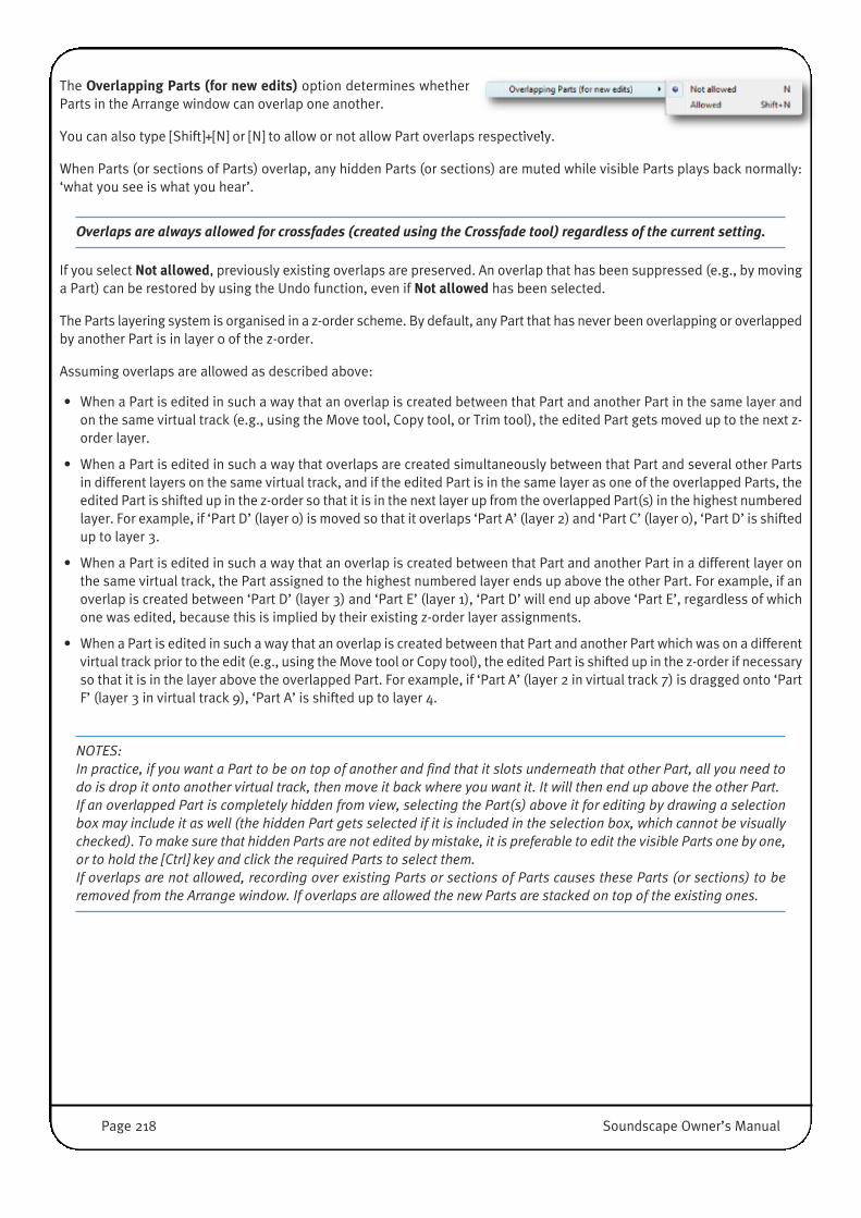
The Overlapping Parts (for new edits) option determines whetherParts in the Arrange window can overlap one another.
You can also type [Shift]+[N] or [N] to allow or not allow Part overlaps respectively.
When Parts (or sections of Parts) overlap, any hidden Parts (or sections) are muted while visible Parts plays back normally:‘what you see is what you hear’.
Overlaps are always allowed for crossfades (created using the Crossfade tool) regardless of the current setting.
If you select Not allowed, previously existing overlaps are preserved. An overlap that has been suppressed (e.g., by movinga Part) can be restored by using the Undo function, even if Not allowed has been selected.
The Parts layering system is organised in a z-order scheme. By default, any Part that has never been overlapping or overlappedby another Part is in layer 0 of the z-order.
Assuming overlaps are allowed as described above:
• When a Part is edited in such a way that an overlap is created between that Part and another Part in the same layer andon the same virtual track (e.g., using the Move tool, Copy tool, or Trim tool), the edited Part gets moved up to the next z-order layer.
• When a Part is edited in such a way that overlaps are created simultaneously between that Part and several other Partsin different layers on the same virtual track, and if the edited Part is in the same layer as one of the overlapped Parts, theedited Part is shifted up in the z-order so that it is in the next layer up from the overlapped Part(s) in the highest numberedlayer. For example, if ‘Part D’ (layer 0) is moved so that it overlaps ‘Part A’ (layer 2) and ‘Part C’ (layer 0), ‘Part D’ is shiftedup to layer 3.
• When a Part is edited in such a way that an overlap is created between that Part and another Part in a different layer onthe same virtual track, the Part assigned to the highest numbered layer ends up above the other Part. For example, if anoverlap is created between ‘Part D’ (layer 3) and ‘Part E’ (layer 1), ‘Part D’ will end up above ‘Part E’, regardless of whichone was edited, because this is implied by their existing z-order layer assignments.
• When a Part is edited in such a way that an overlap is created between that Part and another Part which was on a differentvirtual track prior to the edit (e.g., using the Move tool or Copy tool), the edited Part is shifted up in the z-order if necessaryso that it is in the layer above the overlapped Part. For example, if ‘Part A’ (layer 2 in virtual track 7) is dragged onto ‘PartF’ (layer 3 in virtual track 9), ‘Part A’ is shifted up to layer 4.
NOTES:In practice, if you want a Part to be on top of another and find that it slots underneath that other Part, all you need todo is drop it onto another virtual track, then move it back where you want it. It will then end up above the other Part.If an overlapped Part is completely hidden from view, selecting the Part(s) above it for editing by drawing a selectionbox may include it as well (the hidden Part gets selected if it is included in the selection box, which cannot be visuallychecked). To make sure that hidden Parts are not edited by mistake, it is preferable to edit the visible Parts one by one,or to hold the [Ctrl] key and click the required Parts to select them.If overlaps are not allowed, recording over existing Parts or sections of Parts causes these Parts (or sections) to beremoved from the Arrange window. If overlaps are allowed the new Parts are stacked on top of the existing ones.
Page 218 Soundscape Owner’s Manual

The Multiple Active Parts with same Output andLocation (for new edits) entry lets you determinewhether multiple active Parts that overlap in time
(regardless of their virtual track position) can have the same output assignment (i.e., track assignment).
If Not allowed is selected, whenever an active Part is given a new track assignment,any Parts already assigned to that track which overlap the edited Part in time becomemuted. In the example, Parts A, B, and C are assigned to track 8, (colour-codedyellow), and Parts 1, 2, 3, and 4 are assigned to track 11 (colour-coded green).
The Track Assign tool is then used to change Part C’s track assignment from track 8to track 11. Part 3 and Part 4 are muted as a result.
If Topmost Part (portion) is played is selected, any active Part can be assigned toany track without affecting the mute status of any other active Parts already assignedto that track. It is therefore possible to have overlapping active Parts with the sametrack assignment. If this is the case, in Play mode, Soundscape only plays the topmostPart (or portion) at any given time position. In the example on the right, all the Partsare assigned to the same track.
Part A will be played from bar 297 to bar 301 included, Part 1 will be played only for one bar (bar 301-302), Part B will beplayed from bar 302 to bar 309 included, Part 2 will be played from bar 309 to bar 311 included, Part C will be played frombar 312 to bar 315 included, Part 3 will not be played at all, and Part 4 will be played from 316 on.
If the setting is changed from Topmost Part (portion) is played to Not allowed, active Parts in the same time range whichalready have the same track assignment all remain active (hence the mention ‘for new edits’). In Play mode, at any point inthe timeline, only the topmost of these Parts (or topmost portion) is played. If one such Part is then muted or reassigned toa different track, it can still be restored to its former state by using the ‘Undo’ function.
NOTES: This setting applies to audio and automation Parts.When Topmost Part (portion) is played is selected, depending on the current zoom level and scroll box positions, a Partoutside the visible portion of the Arrangement may be played instead of a visible Part. In particular, when editing at ahigh zoom level, the Part being edited may not be heard in Play mode. It is therefore preferable in this case to use theSolo tool to check an edit.
Soundscape Owner’s Manual Page 219

Mixer PreferencesThe Mixer Preferences include all options for the visual and logicalbehaviour of the Mixer Window.
The default settings are chosen carefully, however, certain work scenariosmay require different settings.
When Auto route is active, the DSP resources are allocatedautomatically to the various mixer elements, including plug-in
effects, etc. When the option is inactive, these resources can be allocated manually by selecting the DSP cells for any MixerColumn upon creation. Mixer Columns can be manually assigned, even if this option is active, by clicking into an empty Mixercolumn area with the I/O Assign Tool.
When Keep Column Selection is selected, a multiple columnselection will remain selected until a new selection is made or an
empty column is selected, rather than deselecting once a tool has been used.
The If Automatic Delay Compensation isactive heading opens a further submenu,giving access to several optional settingsrelating to the operation of the AutomaticDelay Compensation (ADC).
Please refer to Chapter 4: ‘Mix Window’: ‘Automatic Delay Compensation (ADC)’ for more details.
When the Create tool is used in Mix Edit mode to insert a mixerelement into a mixer column, a menu appears that lists all available
mixer elements. The size of this menu can make it difficult to find a particular element, especially if a lot of plug-ins areinstalled or if a small monitor is used. If the Use hierarchical menu for mixer element selection option is enabled, the menuis organised into several sections and pop-up submenus.
When Pass all keyboard input to active mixer element window isenabled, input from the computer keyboard is passed to the active
mixer element or Plug-In window. This may be necessary if the Plug-In provides a special set of Shortcuts or when you needto type in some codes to authorise a VST plug-in.
Note that in this case, the keyboard shortcuts for Soundscape may cease to work properly.
When Treat mixer element parameter changes as mixer filechanges is enabled, a change to a mixer element parameter will
enable the Save Mix function under the File menu. If it is disabled, only changes to the structure or routing of the Mixerenable the Save Mix function.
Clicking on Native mixer elements sample buffer size opens adialogue box where a value in samples can be entered for the
native mixer elements buffer size. The default value is 128. Typically, it should be raised if the PC is struggling to cope withthe processing demands.
Please refer to Chapter 3: ‘Create your first Soundscape Project’ for more details.
Page 220 Soundscape Owner’s Manual

File Manager PreferencesThe File Manager Preferences includes two sub-menus:
The Hide Logical Drive option list allows you to hide drives (that havea Drive Letter) from the Drive Bar of the File Manager window. This isespecially useful, when you want to prevent Read Only Drives(CD/DVD-Rom), Networked Drives , Back-Up Storage or the System
Drive to be accidentally used in a Soundscape recording session.
Selecting/ticking a drive will hide it. You can select Drive Letters from A: to Z:, even if those Driver Letters are currently notassigned.
When Record/Process Folder follows currently displayed folder isactive, Soundscape records or processes new audio and automation
Takes to the currently displayed folder inside the File Manager Window.
This option removes the need to map a Record/Process Folder in any new Arrangement. It resembles the SDisk Folderbehaviour of legacy Soundscape Editor Versions (V5.5 and earlier).
NOTES:Enabling this option can quickly spread the Takes necessary for an Arrangement across multiple folders. Autosave files of the current arrangement and mix are still saved to their original folders.
Remote Control PreferencesThe Remote Control preferences includes two sub-menus, related tocontrol of Soundscape from an external control surface.
Selecting Connect to opens a further submenu, where Soundscapecan be connected to either the Legacy Console Manager or SSLConsole Control application. To run Soundscape with no externalcontrol, deselect the active connection.
When connected to SSL Console Control, selecting Configure / SSLConsole Control... opens the SSL Console Control window forconfiguration
Please see the ‘Console Control’ section of this guide for more details about using either the Legacy Console Manageror SSL Console Control.
Soundscape Owner’s Manual Page 221
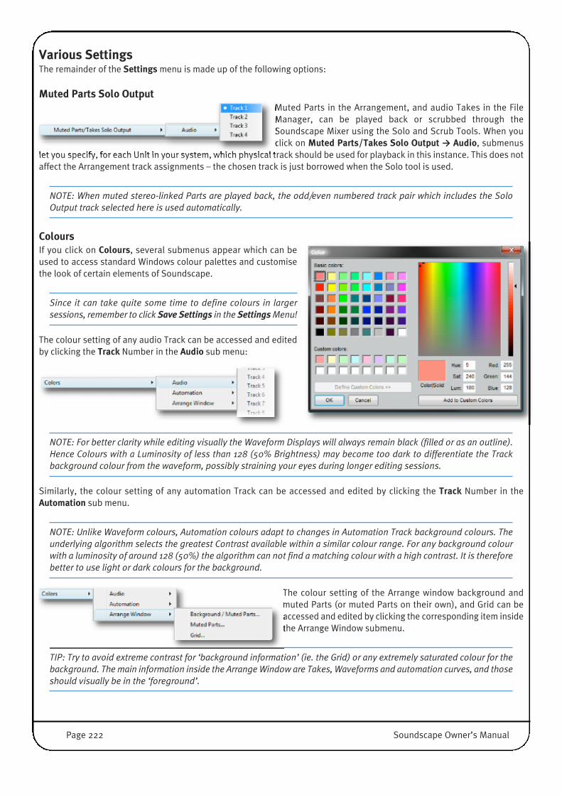
Various SettingsThe remainder of the Settings menu is made up of the following options:
Muted Parts Solo OutputMuted Parts in the Arrangement, and audio Takes in the FileManager, can be played back or scrubbed through theSoundscape Mixer using the Solo and Scrub Tools. When youclick on Muted Parts/Takes Solo Output → Audio, submenus
let you specify, for each Unit in your system, which physical track should be used for playback in this instance. This does notaffect the Arrangement track assignments – the chosen track is just borrowed when the Solo tool is used.
NOTE: When muted stereo-linked Parts are played back, the odd/even numbered track pair which includes the SoloOutput track selected here is used automatically.
ColoursIf you click on Colours, several submenus appear which can beused to access standard Windows colour palettes and customisethe look of certain elements of Soundscape.
Since it can take quite some time to define colours in largersessions, remember to click Save Settings in the SettingsMenu!
The colour setting of any audio Track can be accessed and editedby clicking the Track Number in the Audio sub menu:
NOTE: For better clarity while editing visually the Waveform Displays will always remain black (filled or as an outline).Hence Colours with a Luminosity of less than 128 (50% Brightness) may become too dark to differentiate the Trackbackground colour from the waveform, possibly straining your eyes during longer editing sessions.
Similarly, the colour setting of any automation Track can be accessed and edited by clicking the Track Number in theAutomation sub menu.
NOTE: Unlike Waveform colours, Automation colours adapt to changes in Automation Track background colours. Theunderlying algorithm selects the greatest Contrast available within a similar colour range. For any background colourwith a luminosity of around 128 (50%) the algorithm can not find a matching colour with a high contrast. It is thereforebetter to use light or dark colours for the background.
The colour setting of the Arrange window background andmuted Parts (or muted Parts on their own), and Grid can beaccessed and edited by clicking the corresponding item insidethe Arrange Window submenu.
TIP: Try to avoid extreme contrast for ‘background information’ (ie. the Grid) or any extremely saturated colour for thebackground. The main information inside the Arrange Window are Takes, Waveforms and automation curves, and thoseshould visually be in the ‘foreground’.
Page 222 Soundscape Owner’s Manual
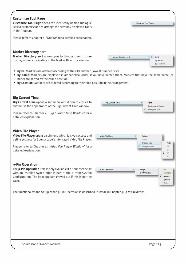
Customize Tool PageCustomize Tool Page opens the identically named DialogueBox to customise and re-arrange the currently displayed Toolsin the Toolbar.
Please refer to Chapter 4: ‘Toolbar’ for a detailed explanation.
Marker Directory sortMarker Directory sort allows you to choose one of threedisplay options for sorting in the Marker Directory Window:
• by ID: Markers are ordered according to their ID number (lowest number first)• by Name: Markers are displayed in alphabetical order, if you have named them. Markers that have the same name (or
none) are sorted by their time position.• by Location: Markers are ordered according to their time position in the Arrangement.
Big Current TimeBig Current Time opens a submenu with different entries tocustomise the appearance of the Big Current Time window.
Please refer to Chapter 4: ‘Big Current Time Window’ for adetailed explanation.
Video File PlayerVideo File Player opens a submenu which lets you access anddefine settings for Soundscape’s integrated Video File Player.
Please refer to Chapter 4: ‘Video File Player Window’ for adetailed explanation.
9-Pin OperationThe 9-Pin Operation item is only available if a Soundscape 32with an installed Sync Option is part of the current SystemConfiguration. The item appears greyed out if this is not thecase.
The functionality and Setup of the 9-Pin Operation is described in Detail in Chapter 4: ‘9 Pin Window’.
Soundscape Owner’s Manual Page 223
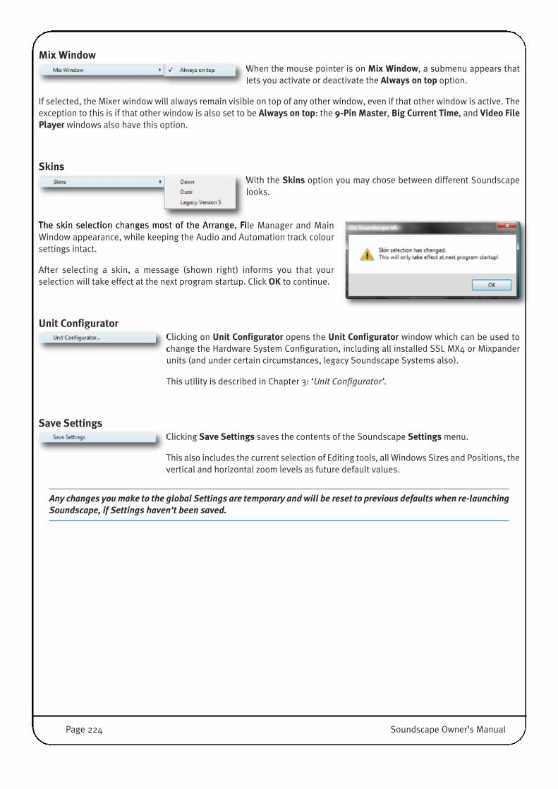
Mix WindowWhen the mouse pointer is on Mix Window, a submenu appears thatlets you activate or deactivate the Always on top option.
If selected, the Mixer window will always remain visible on top of any other window, even if that other window is active. Theexception to this is if that other window is also set to be Always on top: the 9-Pin Master, Big Current Time, and Video FilePlayer windows also have this option.
SkinsWith the Skins option you may chose between different Soundscapelooks.
The skin selection changes most of the Arrange, File Manager and MainWindow appearance, while keeping the Audio and Automation track coloursettings intact.
After selecting a skin, a message (shown right) informs you that yourselection will take effect at the next program startup. Click OK to continue.
Unit ConfiguratorClicking on Unit Configurator opens the Unit Configurator window which can be used tochange the Hardware System Configuration, including all installed SSL MX4 or Mixpanderunits (and under certain circumstances, legacy Soundscape Systems also).
This utility is described in Chapter 3: ‘Unit Configurator’.
Save SettingsClicking Save Settings saves the contents of the Soundscape Settings menu.
This also includes the current selection of Editing tools, all Windows Sizes and Positions, thevertical and horizontal zoom levels as future default values.
Any changes you make to the global Settings are temporary and will be reset to previous defaults when re-launchingSoundscape, if Settings haven't been saved.
Page 224 Soundscape Owner’s Manual
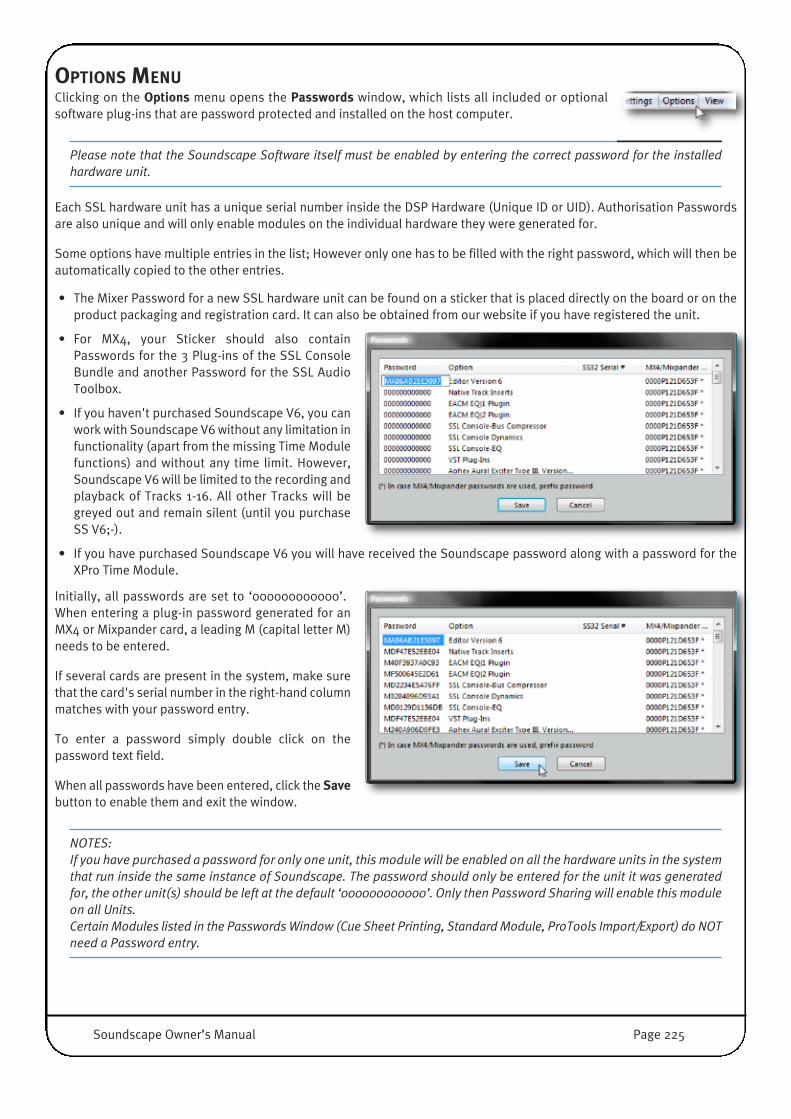
OPTIONS MENUClicking on the Options menu opens the Passwords window, which lists all included or optionalsoftware plug-ins that are password protected and installed on the host computer.
Please note that the Soundscape Software itself must be enabled by entering the correct password for the installedhardware unit.
Each SSL hardware unit has a unique serial number inside the DSP Hardware (Unique ID or UID). Authorisation Passwordsare also unique and will only enable modules on the individual hardware they were generated for.
Some options have multiple entries in the list; However only one has to be filled with the right password, which will then beautomatically copied to the other entries.
• The Mixer Password for a new SSL hardware unit can be found on a sticker that is placed directly on the board or on theproduct packaging and registration card. It can also be obtained from our website if you have registered the unit.
• For MX4, your Sticker should also containPasswords for the 3 Plug-ins of the SSL ConsoleBundle and another Password for the SSL AudioToolbox.
• If you haven't purchased Soundscape V6, you canwork with Soundscape V6 without any limitation infunctionality (apart from the missing Time Modulefunctions) and without any time limit. However,Soundscape V6 will be limited to the recording andplayback of Tracks 1-16. All other Tracks will begreyed out and remain silent (until you purchaseSS V6;-).
• If you have purchased Soundscape V6 you will have received the Soundscape password along with a password for theXPro Time Module.
Initially, all passwords are set to ‘000000000000’.When entering a plug-in password generated for anMX4 or Mixpander card, a leading M (capital letter M)needs to be entered.
If several cards are present in the system, make surethat the card's serial number in the right-hand columnmatches with your password entry.
To enter a password simply double click on thepassword text field.
When all passwords have been entered, click the Savebutton to enable them and exit the window.
NOTES: If you have purchased a password for only one unit, this module will be enabled on all the hardware units in the systemthat run inside the same instance of Soundscape. The password should only be entered for the unit it was generatedfor, the other unit(s) should be left at the default ‘000000000000’. Only then Password Sharing will enable this moduleon all Units.Certain Modules listed in the Passwords Window (Cue Sheet Printing, Standard Module, ProTools Import/Export) do NOTneed a Password entry.
�
Soundscape Owner’s Manual Page 225

VIEW MENUOverview This menu allows you to configure the appearance and visibility of Soundscape'sfunctional Windows.
The following windows can be resized and positioned anywhere on Windows Desktop,including extended Desktops for Multi-Monitor Setups:• The Tool Bar, Status Bar and Tape Transport Bar within the Main Soundscape
window• Arrange Window with its Time Axis and Marker Bar [A]• File Manager window [D]• Marker Directory window [W]• Big Current Time window [T]• Video File Player window [V]• Mix Window [Q] or [X]
The Tool Bar, Status Bar, Tape Transport Bar, and Marker Bar can be shown or hiddenby clicking the corresponding menu entry.
The following windows cannot be resized, but can be positioned freely• Buffer Activity window [B]• 9-Pin Window [U]
All screen settings including size and positions can be saved by clicking Save Settings in the Settings menu.
The Next Tool Page and Prev Tool Page [PgUp]/[PgDown] items can be used to scroll through the Tool Pages.
GridThe Grid entry shows or hides the Arrange window’s grid. The grid is composed of horizontal lines which indicate virtualtrack positions, and vertical lines which indicate time subdivisions.
If the Time Axis is set to SMPTE time in the Settings menu, the highestpossible zoom level will display one vertical line per frame. If the Time Axis isset to bars/counts/ticks, the highest possible zoom level will display onevertical line for every four ticks (there are 960 ticks per quarter note).
Dock Arrange window & File ManagerSelecting Dock Arrange Window & File Manager docks the Arrange and File Manager windows to the Main window, savingscreen real estate and allowing proportional adjustment of both windows when resizing the main window. Sliding theseparator line between the Arrange Window and File Manager also makes it easy to gain space in one window while the otherone shrinks accordingly.
NOTE: When this is active, you cannothide the Arrange or File Manager Windowwith either Menu entries or keyboardshortcuts.
Page 226 Soundscape Owner’s Manual

HELP MENUThe Help menu allows direct access to the Readme Notes, including last version changes, alongwith the About SSL Soundscape Window which displays additional System Information.
All Soundscape related User Guides can also be accessed from this Menu (including this UserGuide).
User GuidesClicking on any User Guide (MX4 hardware installation, Soundscape V6.2, features new to v6.2, and SSL Console Bundle)opens it in a PDF Format inside an appropriate reader application.
Note that you will need to ensure that you have a PDF Reader installed on your System.
Read Me notesThe Readme Notes contain the latest changes in software revision. They may contain important last minute changes whichhave not yet made it into the User Manual.
About SSL SoundscapeThis entry opens a typical About.. Window, with Software VersionInformation, some licensing and copyright info and a nice and polishedgraphic:)�
Note that you may frequently need the Information at the bottom of thiswindow, where all currently configured Units are listed with their uniqueserial number (UID). The UID is required whenever you want to purchaseadditional software modules or want to register the hardware on ourwebsite. In addition, our Service Department or your Dealer/Distributormay want to know this number in case you need any help, so pleaseremember this window.
Click OK to close the window.
Soundscape Owner’s Manual Page 227
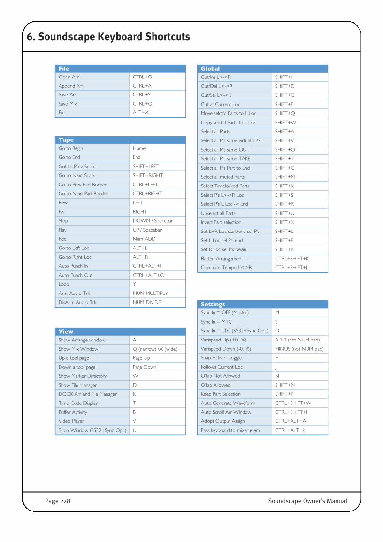
6. Soundscape Keyboard Shortcuts
FileOpen Arr CTRL+O
Append Arr CTRL+A
Save Arr CTRL+S
Save Mix CTRL+Q
Exit ALT+X
GlobalCut/Ins L<->R SHIFT+I
Cut/Del L<->R SHIFT+D
Cut/Sel L<->R SHIFT+C
Cut at Current Loc SHIFT+F
Move selct‘d Parts to L Loc SHIFT+Q
Copy selct‘d Parts to L Loc SHIFT+W
Select all Parts SHIFT+A
Select all P‘s same virtual TRK SHIFT+V
Select all P‘s same OUT SHIFT+O
Select all P‘s same TAKE SHIFT+T
Select all P‘s Part to End SHIFT+G
Select all muted Parts SHIFT+M
Select Timelocked Parts SHIFT+K
Select P‘s L<->R Loc SHIFT+S
Select P‘s L Loc -> End SHIFT+R
Unselect all Parts SHIFT+U
Invert Part selection SHIFT+X
Set L+R Loc start/end sel P‘s SHIFT+L
Set L Loc sel P‘s end SHIFT+E
Set R Loc sel P‘s begin SHIFT+B
Flatten Arrangement CTRL+SHIFT+K
Compute Tempo L<->R CTRL+SHIFT+J
ViewShow Arrange window A
Show Mix Window Q (narrow) /X (wide)
Up a tool page Page Up
Down a tool page Page Down
Show Marker Directory W
Show File Manager D
DOCK Arr and File Manager K
Time Code Display T
Buffer Activity B
Video Player V
9-pin Window (SS32+Sync Opt.) U
TapeGo to Begin Home
Go to End End
Got to Prev Snap SHIFT+LEFT
Go to Next Snap SHIFT+RIGHT
Go to Prev Part Border CTRL+LEFT
Go to Next Part Border CTRL+RIGHT
Rew LEFT
Fw RIGHT
Stop DOWN / Spacebar
Play UP / Spacebar
Rec Num ADD
Go to Left Loc ALT+L
Go to Right Loc ALT+R
Auto Punch In CTRL+ALT+I
Auto Punch Out CTRL+ALT+O
Loop Y
Arm Audio Trk NUM MULTIPLY
DisArm Audio Trk NUM DIVIDE SettingsSync In = OFF (Master) M
Sync In = MTC S
Sync In = LTC (SS32+Sync Opt.) O
Varispeed Up (+0.1%) ADD (not NUM pad)
Varispeed Down (-0.1%) MINUS (not NUM pad)
Snap Active - toggle H
Follows Current Loc J
O‘lap Not Allowed N
O‘lap Allowed SHIFT+N
Keep Part Selection SHIFT+P
Auto Generate Waveform CTRL+SHIFT+W
Auto Scroll Arr Window CTRL+SHIFT+I
Adopt Output Assign CTRL+ALT+A
Pass keyboard to mixer elem CTRL+ALT+K
Page 228 Soundscape Owner’s Manual

Various Mouse and Key ActionsCreate Record Track (Audio/Auto) Right-Click RecTrkColumn (Left side Arr Window)
Centre Current Loc in Arr Window C
Place Left Locator at Current Loc L
Place Right Locator at Current Loc R
Preview Take in File Manager Right-Click+Hold on icon/name +move mouse
Add Marker at Current Loc INSERT
Add Numbered Marker at Current Loc (Enter Marker No)+INSERT
Move Current Loc to Marker (Enter Marker No)+DOWN, orRight-Click in Marker Window
Move Current Loc to Marker & Play (Enter Marker No)+UP
Move Marker to Current Loc (Enter Marker No)+ ENTER
Move Left Locator to here Left-Click on Time Axis Bar
Move Right Locator to here Right-Click on Time Axis Bar
EditCreate ALT+1 (number one) Noise Gate CTRL+K
Track Assign CTRL+1 (number one) Waveform CTRL+W
Move CTRL+M Info CTRL+I (letter i)
Move Vert CTRL+SHIFT+M Delete CTRL+D / DEL
Move Loc CTRL+ALT+M Stereo Link CTRL+L
Copy CTRL+C Multi-Ch Link CTRL+4
Copy Vert CTRL+SHIFT+C Slip CTRL+J
Copy Loc CTRL+ALT+C Invert Phase CTRL+P
Cut CTRL+X Repeat CTRL+R
Cut Loc CTRL+ALT+X Timelock CTRL+SHIFT+L
Volume Tool CTRL+V Auto-Curve Select CTRL+SHIFT+A
Vol Fade In CTRL+E Auto Event Edit CTRL+SHIFT+E
Vol Fade Out CTRL+F Thin Auto Events CTRL+SHIFT+F
Vol Trim CTRL+SHIFT+V Context Sensitive CTRL+2
Trim CTRL+T Snap Point Edit CTRL+SHIFT+D
Trim Adjacent CTRL+ALT+T Mix Edit E
Scrub Solo CTRL+B Auto Enable G
Scrub All CTRL+SHIFT+B ADC CTRL+ALT+D
DC Offset CTRL+SHIFT+N Auto Snapshot F
Normalize CTRL+N Zoom IN H ALT+RIGHT
SRate CTRL+SHIFT+S Zoom OUT H ALT+LEFT
Pitch CTRL+SHIFT+P Zoom IN V ALT+UP
Time Stretch CTRL+SHIFT+T Zoom OUT V ALT+DOWN
Reverse Tool CTRL+SHIFT+R Scroll Left CTRL+ALT+LEFT
Mute CTRL+U Scroll Right CTRL+ALT+RIGHT
Glue CTRL+G Scroll Up CTRL+ALT+UP
Crop CTRL+3 Scroll Down CTRL+ALT+DOWN
Solo CTRL+H Zoom Down Z (1x=rect, 2x=prev)
Solo from Loc CTRL+SHIFT+H Zoom Up SHIFT+Z (as above)
Consolidate CTRL+SHIFT+G Undo CTRL+Z
Crossfade CTRL+SHIFT+X Redo CTRL+Y
Mixdown CTRL+SHIFT+Y External Offline Process (Xpro) CTRL+ALT+E
Soundscape Owner’s Manual Page 229

Various Mouse and Key Actions (continued)
Move Current Loc to here SHIFT+Left-Click on Time Axis Bar
Move Current Loc to L Loc Left-Click on Left Loc Button (below Display)
Move Current Loc to R Loc Left-Click on Right Loc Button (below Display)
Song Position (User Enter Value) Left-Click on Song Position Time Display
Current Locator (User Enter Value) Left-Click on SMPTE Time Display
Left Locator (User Enter Value) Left-Click on Left Locator Time Display
Right Locator (User Enter Value) Left-Click on Right Loc Button (below Display)
Sign (User Enter Value) Left-Click on Sign Display
Tempo (User Enter Value) Left-Click on Tempo Display
Selct Multiple Parts in Arr Hold Down Ctrl, Left-Click on Parts
Selct all Parts from Sel Prt to End Hold Down Shift & Control, Left-Click on Part
DEL selct‘d Parts (ArrWind active) DELETE key
DEL selct‘d File/Folder (FileManWind active) DELETE key
DEL selct‘d Marker(s) (MarkWin active) DELETE key
Mixer Inactive Build Hold SHIFT while editing mixer
(... to enable an Inactive Mixer) ... last mixer edit w/o SHIFTDouble-Click Mix Window caption bar
Select tool to L or R mouse button Left-Click or Right-Click on tool in ToolBar
Select tool to Alt+L or Alt+R mouse ALT+Left-Click or ALT+Right-Click on tool in ToolBar
Up a tool page Right-Click on ToolBar page icon
Down a tool page Left-Click on ToolBar page icon
Customize Context Sensitive Edit Tool Double-Click on SwissArmyKnife Icon
Customize Cross-Fade Settings Double-Click on CrossFade Tool
Customize ToolBar Settings Double-Click on blank part of ToolBar
Zoom Box (for Arr... to zoom in) Left-Click Zoom Tool-> draw zoom
Zoom Out (for Arr... to zoom out) Double-Click ZoomTool
Magnify Waveform display in Part Right-Click on Zoom IN Vert
Un-Magnify Waveform display in Part Right-Click on Zoom OUT Vert
Select Multiple SOLO buttons in Mixer Hold CTRL while Left-Click or Right-Click solo buttons
Select default response to Pop Ups Spacebar or Enter
Cancel Processing Tools Spacebar or Enter
Nudging with
Move or Copy
on left Mouse
1 Track Up Left-Click+UP
1 Track Down Left-Click+DOWN
Previous Snap Point Left-Click+LEFT
Next Snap Point Left-Click+RIGHT
Trim Tool
on left Mouse
Trim Part Previous Snap Point Left-Click+UP
Trim Part to Next Snap Point Left-Click+DOWN
Slip Tool
on left Mouse
Slip Part Previous Snap Point Left-Click+LEFT
Slip Part Next Snap Point Left-Click+RIGHT
Snap Point Edit Tool on left Mouse
Reset Snap Point Double-Click on Part
Volume & Fade Tool;
Noise Gate Parameters
PopUp
Increase sel fader (fast) Page Up
Decrease sel fader (fast) Page Down
Increase sel fader (slow) UP or LEFT
Decrease sel fader (slow) DOWN or RIGHT
Context Sensitive Edit
Tool (SwissArmyKnife)
Floating Dropdown Menu Right-Click on Part
ZOOM Right-Click Part, move mouse
Scroll Part in Arr Window ALT+Right-Click, move mouse
Page 230 Soundscape Owner’s Manual
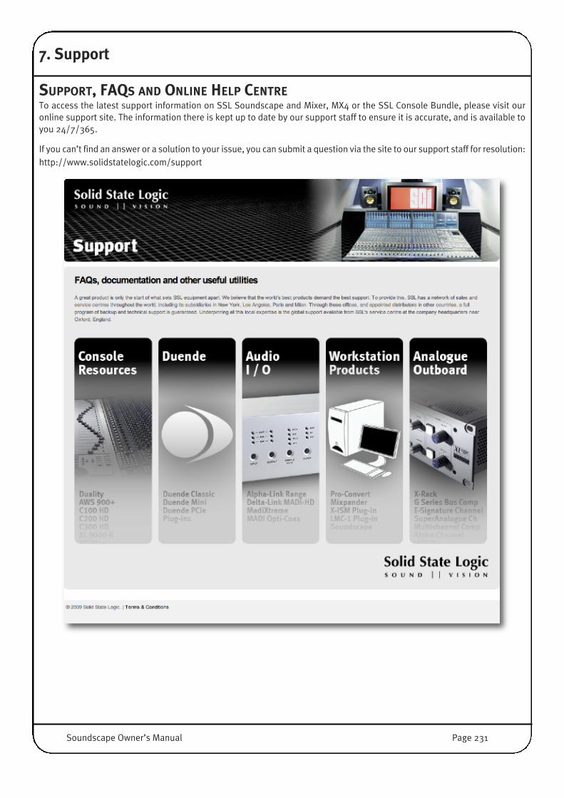
7. Support
SUPPORT, FAQS AND ONLINE HELP CENTRETo access the latest support information on SSL Soundscape and Mixer, MX4 or the SSL Console Bundle, please visit ouronline support site. The information there is kept up to date by our support staff to ensure it is accurate, and is available toyou 24/7/365.
If you can’t find an answer or a solution to your issue, you can submit a question via the site to our support staff for resolution:http://www.solidstatelogic.com/support
Soundscape Owner’s Manual Page 231

This page is intentionally almost blank

Index
9-Pin Control 170, 223
Aadc 115Alpha-Link 87Append Arr... 178Append Mix... 181Appending Arrangements 31, 178Appending Mixer Files 78, 181Arrange Window 30, 158Arrangement Navigation 38Arrangement Parts 40Arrangement Preferences 214Assign tool 47, 76Audio Buffer Activity window 175Audio Cards 6Audio File conversion 159Audio Toolbox plug-ins 108Auditioning 157Authorising software 15Auto Punch In/Out 35, 41, 45, 193Auto route (DSP) 84Auto Scroll 42Auto stop 36Automatic Delay Compensation 115Automation 20, 68, 118Automation editing 124Automation Record Modes 119Automation Setup 212AVID 167
Bbalance 81, 94Big Current Time 223Big Current Time window 174, 223bit resolution 29busses 79
CChorus 108Clock Synchronisation 13Colours display 222Compressor 109Console Control 128Console Manager 147Consolidate Process tool 63Context Sensitive tool 71Convert project 159Convert WAV/BWF files 156Copy Active files to this folder 154Copy tool 49, 76Copying Mixer Strips 78Create Arrangments 30Create Folder 153Create Mixer 180
Create tool 76, 79Creating Mixer Strips 77Crop tool 50Crossfade 69Cubase 167Cue Sheet 73Current Locator 42Customize Tool Page 223Cut tool 49
DDC Removal 57Deglitch 212Delay 111Delay Compensation 115Delete empty Folder trees only 155Delete tool 64, 76Deleting Mixer Strips 78Dither 111Dock Arrange Window & File Manager 226Domain Root Folder 153drive 152DSP plug-ins 102DSP Resources 83, 88Dynamic automation 118Dynamics 109, 137
Eedit (Mixer) 76Edit Menu 194Editing Tools 47EPP 94EQ 103, 137Equal Power Panning 94Event Thinning Tool 21, 68, 126Expander 109export project 159
Ffade 69Fade tool 52, 53Fader Groups 82Faders 106fast-forward 44File List Sorting 152File Manager 23, 151, 221, 226File Menu 177Flanger 108Foot Switch Control 143format 29Full View mode 85
GGate 60, 109Global Menu 195Glue tool 57Go to Arrangement Folder 153Go to Mixer Folder 153
Soundscape Owner’s Manual Page 233

Go to Record/Process Folder 153Grid 226groups 82
HHelp Menu 227
II/O Assign tool 76, 91I/O Mode 14, 205import project 159Inactive Build (Mixer) 88Info tool 62, 76, 123input elements 105Input/Output Identification 87Installation 8internal busses 79
JJogwheel 129, 143
KKey commands 2Keyboard Shortcuts 228
LL<−>R Readout 29Limiter 109Loading Mixers 75Locators 41, 42, 43Logic 167Loop Recording 36, 45, 193
MMadiXtreme 6, 87Main Screen 23Mark as Domain Root Folder 153Mark as Record/Process Folder 153Marker Directory sort 223Markers 42Master Clock 13, 29, 202Maximum record time 211MCU controllers 128Menu Reference 177Mix Edit mode 76Mix Input Always 91Mix Window 75, 77, 224Mixdown 58Mixer 11Mixer Automation 118Mixer Columns 32, 75, 76, 77, 80Mixer Editing Tools 76mixer elements 79, 80Mixer Preferences 220Mixpander 6, 87mouse 25Move Active files to this folder 154Move tool 48, 76Moving Mixer Strips 78
MPEG Import and Export 185MS Decoder 106Multi-Channel Link 65Mute Groups 82Mute tool 57, 76Muted Parts Solo Output 222MX4 6, 87
NNew Arr... 177New Arrangement 30, 177New Mix 180Noise Gate 60Noise shaping 111Normalise tool 56Nuendo 167
OOMF Composition 182Open Arr... 178Open Arrangement 31, 178Open Mix 180Open Video File 191Opening Mixers 75, 180Options menu 15, 225output elements 105
Ppan 81, 94Part volume tool 52Parts 40Passwords 15, 225Peak Meters 106Phase Invert 67Pitch Shift 56Play 44plug-ins 10, 102, 112, 136postroll 36, 211Preferences menu 212preroll 36, 211Pro-Convert 159, 179Project Conversion 159Properties 157Protools 167, 187Punch In/Out 33, 35, 41, 193
RReading conventions 2Rec Fmt 29Record button 44Record Format 29, 201Record Setup 36, 211Record Tracks 32Record/Process folder 153Recording Audio 33Redo 194Repeat tool 67Replace Take(s) 156
Page 234 Soundscape Owner’s Manual
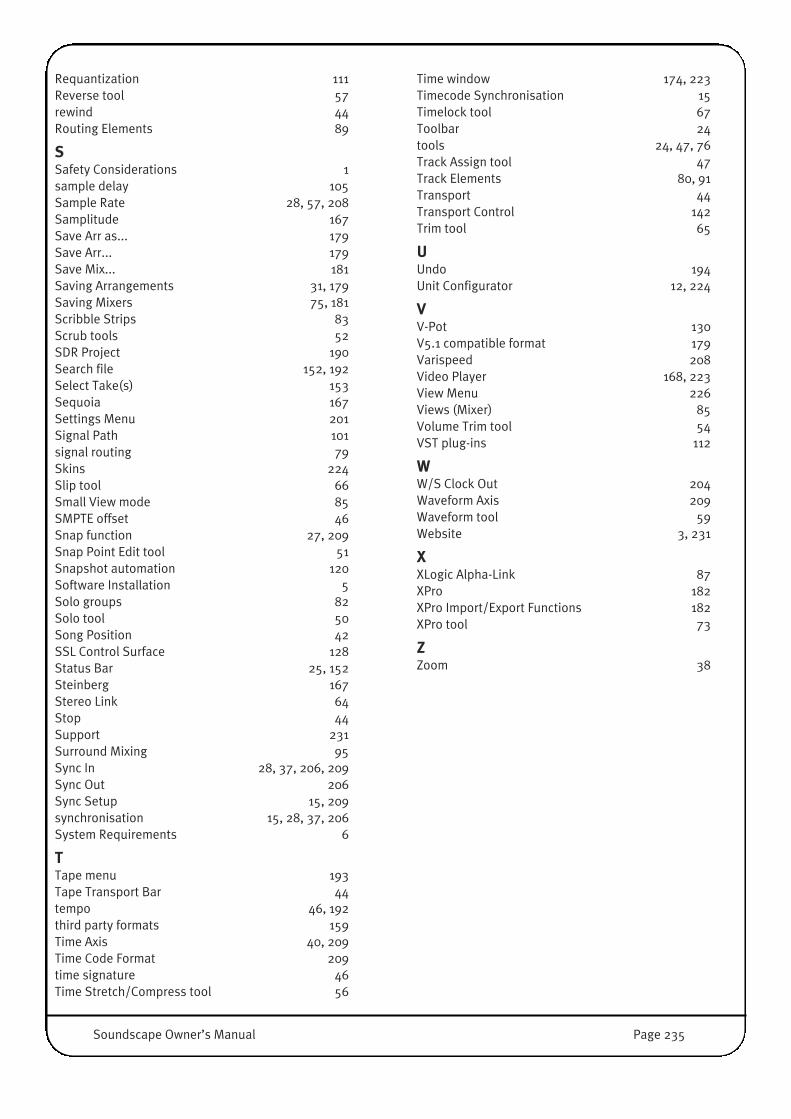
Requantization 111Reverse tool 57rewind 44Routing Elements 89
SSafety Considerations 1sample delay 105Sample Rate 28, 57, 208Samplitude 167Save Arr as... 179Save Arr... 179Save Mix... 181Saving Arrangements 31, 179Saving Mixers 75, 181Scribble Strips 83Scrub tools 52SDR Project 190Search file 152, 192Select Take(s) 153Sequoia 167Settings Menu 201Signal Path 101signal routing 79Skins 224Slip tool 66Small View mode 85SMPTE offset 46Snap function 27, 209Snap Point Edit tool 51Snapshot automation 120Software Installation 5Solo groups 82Solo tool 50Song Position 42SSL Control Surface 128Status Bar 25, 152Steinberg 167Stereo Link 64Stop 44Support 231Surround Mixing 95Sync In 28, 37, 206, 209Sync Out 206Sync Setup 15, 209synchronisation 15, 28, 37, 206System Requirements 6
TTape menu 193Tape Transport Bar 44tempo 46, 192third party formats 159Time Axis 40, 209Time Code Format 209time signature 46Time Stretch/Compress tool 56
Time window 174, 223Timecode Synchronisation 15Timelock tool 67Toolbar 24tools 24, 47, 76Track Assign tool 47Track Elements 80, 91Transport 44Transport Control 142Trim tool 65
UUndo 194Unit Configurator 12, 224
VV-Pot 130V5.1 compatible format 179Varispeed 208Video Player 168, 223View Menu 226Views (Mixer) 85Volume Trim tool 54VST plug-ins 112
WW/S Clock Out 204Waveform Axis 209Waveform tool 59Website 3, 231
XXLogic Alpha-Link 87XPro 182XPro Import/Export Functions 182XPro tool 73
ZZoom 38
Soundscape Owner’s Manual Page 235
www.solidstatelogic.com
Visit SSL at: www.solid-state-logic.com
82BSSP01A
© Solid State LogicAll Rights reserved under International and Pan-American Copyright Conventions
Console Control, MadiXtreme, Matrix, Mixpander, MX4, Nucleus, Pro-Convert and Soundscape are trademarks of Solid State Logic
All other product names and trademarks are the property of their respective owners and are herebyacknowledged
No part of this publication may be reproduced in any form or by any means, whether mechanical orelectronic, without the written permission of Solid State Logic, Oxford, OX5 1RU, England
As research and development is a continual process, Solid State Logic reserves the right to change thefeatures and specifications described herein without notice or obligation.
Solid State Logic cannot be held responsible for any loss or damage arising directly or indirectly fromany error or omission in this manual.
E&OE