SOPC Builder PTF File Reference Manual -...
232
Reference Manual SOPC Builder PTF File 101 Innovation Drive San Jose, CA 95134 (408) 544-7000 http://www.altera.com Document Version: 1.1 Document Date: September 2002
Transcript of SOPC Builder PTF File Reference Manual -...

Reference Manual
SOPC Builder PTF File
101 Innovation DriveSan Jose, CA 95134(408) 544-7000http://www.altera.com
Document Version: 1.1Document Date: September 2002

ii Altera CorporationMNL-SOPCPTF-1.1
Copyright Nios Peripherals Reference Manual
Copyright © 2002 Altera Corporation. All rights reserved. Altera, The Programmable Solutions Company, the stylized Altera logo,specific device designations, and all other words and logos that are identified as trademarks and/or service marks are, unlessnoted otherwise, the trademarks and service marks of Altera Corporation in the U.S. and other countries. All other product orservice names are the property of their respective holders. Altera products are protected under numerous U.S. and foreign patentsand pending applications, mask work rights, and copyrights. Altera warrants performance of its semiconductorproducts to current specifications in accordance with Altera’s standard warranty, but reserves the right to makechanges to any products and services at any time without notice. Altera assumes no responsibility or liabilityarising out of the application or use of any information, product, or service described herein except as expresslyagreed to in writing by Altera Corporation. Altera customers are advised to obtain the latest version of devicespecifications before relying on any published information and before placing orders for products or services.

Altera Corporation
About this Manual
This reference manual is for IP developers who wish to create new library components for SOPC Builder. It contains reference material on the internal workings of SOPC Builder which may also be useful to advanced system–on–a–programmable–chip (SOPC) system-designers.
Table 1 shows the manual revision history.
How to Find Information
� The Adobe Acrobat Find feature allows you to search the contents of a PDF file. Click the binoculars toolbar icon to open the Find dialog box.
� Bookmarks serve as an additional table of contents.� Thumbnail icons, which provide miniature previews of each page,
provide a link to the pages.� Numerous links, shown in green text, allow you to jump to related
information.
Table 1. Manual Revision History
Date Description
September 2002 Updates for SOPC Builder 2.7 release.
August 2002 Initial version of PDF manual (web only). This document was created for SOPC Builder version 2.6
iii
About this Manual SOPC Builder PTF File Reference Manual
How to Contact Altera
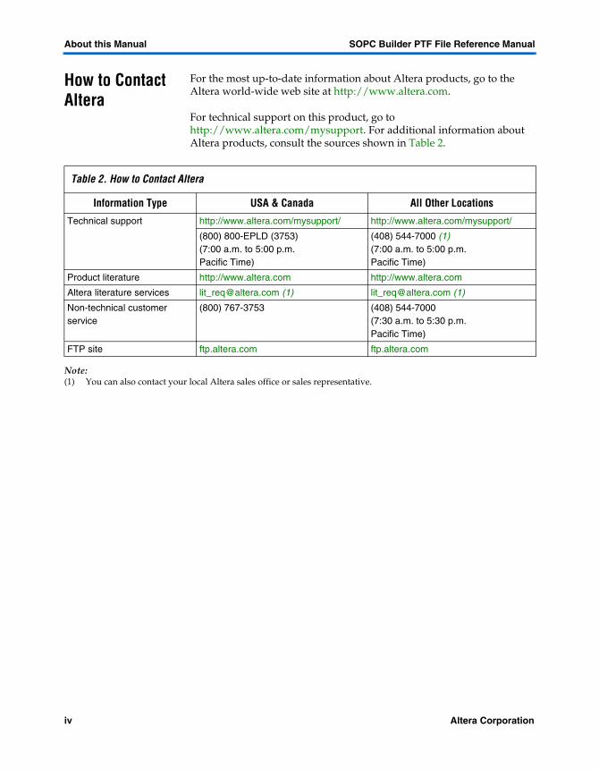
For the most up-to-date information about Altera products, go to the Altera world-wide web site at http://www.altera.com.
For technical support on this product, go to http://www.altera.com/mysupport. For additional information about Altera products, consult the sources shown in Table 2.
Note:(1) You can also contact your local Altera sales office or sales representative.
Table 2. How to Contact Altera
Information Type USA & Canada All Other Locations
Technical support http://www.altera.com/mysupport/ http://www.altera.com/mysupport/
(800) 800-EPLD (3753)(7:00 a.m. to 5:00 p.m. Pacific Time)
(408) 544-7000 (1)(7:00 a.m. to 5:00 p.m. Pacific Time)
Product literature http://www.altera.com http://www.altera.com
Altera literature services [email protected] (1) [email protected] (1)
Non-technical customer service
(800) 767-3753 (408) 544-7000 (7:30 a.m. to 5:30 p.m. Pacific Time)
FTP site ftp.altera.com ftp.altera.com
iv Altera Corporation

SOPC Builder PTF File Reference Manual About this Manual
Typographic Conventions
The SOPC Builder PTF File Reference Manual uses the typographic conventions shown in Table 3.
Table 3. Conventions
Visual Cue Meaning
Bold Type with Initial Capital Letters
Command names, dialog box titles, checkbox options, and dialog box options are shown in bold, initial capital letters. Example: Save As dialog box.
bold type External timing parameters, directory names, project names, disk drive names, filenames, filename extensions, and software utility names are shown in bold type. Examples: fMAX, \qdesigns directory, d: drive, chiptrip.gdf file.
Italic Type with Initial Capital Letters
Document titles are shown in italic type with initial capital letters. Example: AN 75: High-Speed Board Design.
Italic type Internal timing parameters and variables are shown in italic type. Examples: tPIA, n + 1.Variable names are enclosed in angle brackets (< >) and shown in italic type. Example: <file name>, <project name>.pof file.
Initial Capital Letters Keyboard keys and menu names are shown with initial capital letters. Examples: Delete key, the Options menu.
“Subheading Title” References to sections within a document and titles of on-line help topics are shown in quotation marks. Example: “Typographic Conventions.”
Courier type PTF-files sections, assignments, and values are shown in courier. However, assignments in tables and bullet items are not shown in Courier.
Signal and port names are shown in lowercase Courier type. Examples: data1, tdi, input. Active-low signals are denoted by suffix n, e.g., resetn.
Anything that must be typed exactly as it appears is shown in Courier type. For example: c:\qdesigns\tutorial\chiptrip.gdf. Also, sections of an actual file, such as a Report File, references to parts of files (e.g., the AHDL keyword SUBDESIGN), as well as logic function names (e.g., TRI) are shown in Courier.
1., 2., 3., and a., b., c.,... Numbered steps are used in a list of items when the sequence of the items is important, such as the steps listed in a procedure.
� Bullets are used in a list of items when the sequence of the items is not important.
v The checkmark indicates a procedure that consists of one step only.
1 The hand points to information that requires special attention.
r The angled arrow indicates you should press the Enter key.
f The feet direct you to more information on a particular topic.
Altera Corporation v

Contents
About this Manual ...................................................................................................................................... iiiHow to Find Information .............................................................................................................. iiiHow to Contact Altera .................................................................................................................. ivTypographic Conventions ..............................................................................................................v
Overview ........................................................................................................................................................15Introduction ....................................................................................................................................15
SOPC Builder Background Information .............................................................................15SOPC Builder & PTF File Basics ..................................................................................................15
SOPC Builder: Two Loosely-Coupled Tools ......................................................................16Two PTF File Types .......................................................................................................................17
System PTF Files ....................................................................................................................18class.ptf Files ...........................................................................................................................19How class.ptf and System PTF Files Relate .......................................................................20
Creating a MODULE section ........................................................................................21SOPC Builder Design Flow ..................................................................................................25Component Authoring ..........................................................................................................25System Assembly ...................................................................................................................25System Generation .................................................................................................................26SOPC Builder Phase Sequence .............................................................................................26The Component Authoring Phase .......................................................................................28The Add Phase .......................................................................................................................28The Edit Phase ........................................................................................................................29System Configuration ............................................................................................................30Bind Phase ...............................................................................................................................30SDK Generation Phases .........................................................................................................30Module Generator Program Phases ....................................................................................30
Module Default Generator Program ...........................................................................31The Bus Generation Phase ....................................................................................................33The Top-Module Generation Phase ....................................................................................35The Project File Generation Phase .......................................................................................35
Synthesis-Control Files ..................................................................................................35Simulation Project Generation .....................................................................................35Command Line System Generation Script .................................................................37
Quartus II Software Synthesis ..............................................................................................37PTF Files ..........................................................................................................................................37
PTF Syntax Described ............................................................................................................37PTF Assignments ...........................................................................................................38PTF Sections ....................................................................................................................39
Altera Corporation vii
Contents SOPC Builder PTF File Reference Manual
Recognized and Unrecognized Data ...........................................................................40The Current Project Directory ..............................................................................................40How are Top-Level I/O Ports Named? ..............................................................................41
Global Port Inputs ..........................................................................................................42Un-shared Ports to Module ..........................................................................................43Shared Ports to Modules ...............................................................................................43Non-System Bus Ports ...................................................................................................44
Walk-through examples ................................................................................................................45Simple Example (non-parameterized component) ...........................................................45Complex Example (Highly-Parameterized) Component .................................................49
SDK Generation ...........................................................................................................................................56Introduction ....................................................................................................................................56
SDK Generation ......................................................................................................................56PTF Entries for Peripherals ...........................................................................................................57
Example From altera_avalon_uart ......................................................................................57General Layout .......................................................................................................................58Filtering By CPU And Toolchain .........................................................................................58Assignments Within an SDK_FILES Section .....................................................................59
PTF Entries for CPUs .....................................................................................................................59Example from altera_nios .....................................................................................................59General Layout .......................................................................................................................61Assignments Within the CPU Section ................................................................................61The QUARTUS_TCL_SCRIPT Section ................................................................................61
SWB_ASSIGNMENTS ...................................................................................................62
PTF File Sections ........................................................................................................................................63CLASS <class_name>/SDK_GENERATION/SDK_FILES .............................................63CLASS <class_name>/SDK_GENERATION /CPU Section ..........................................63CLASS <class_name>/SDK_GENERATION/CPU/QUARTUS_TCL_ SCRIPT Section 64CLASS <class_name>/SDK_GENERATION/CPU/QUARTUS_TCL_ SCRIPT/ SWB_ASSIGNMENT Section ...............................................................................................64CLASS <class_name>/ASSOCIATED_FILES ...................................................................64CLASS <class_name>/DEFAULT_GENERATOR ...........................................................64CLASS <class_name>/USER_INTERFACE/USER_LABELS .........................................65CLASS <class_name>/USER_INTERFACE/WIZARD_UI ............................................65SYSTEM <system_name> .....................................................................................................65SYSTEM <system_name>/MODULE <module_name> .................................................66SYSTEM <system_name>/MODULE <module_name>/ WIZARD_SCRIPT_ARGUMENTS ......................................................................................66SYSTEM <system_name>/MODULE<module_name>/ WIZARD_SCRIPT_ARGUMENTS/CONTENTS srec .....................................................67SYSTEM <system_name>/MODULE <module_name>/ WIZARD_SCRIPT_ARGUMENTS/CONSTANTS/CONSTANT <const_name> ......67SYSTEM <system_name>/MODULE <module_name>/HDL_INFO ..........................68
viii Altera Corporation

SOPC Builder PTF File Reference Manual Contents
SYSTEM <system_name>/MODULE <module_name>/MASTER <master_name> .68SYSTEM <system_name>/MODULE <module_name>/ MASTER<master_name>/ PORT_WIRING/PORT <port_name> ................................................................................69SYSTEM <system_name>/MODULE <module_name>/SLAVE <slave_name> .......69SYSTEM <system_name>/MODULE <module_name>/PORT_WIRING ..................70
What does SOPC Builder do with the Ports on a Module? .....................................72Special Rules for Port-Type ..........................................................................................75
PORT_WIRING sections & SOPC Builder Phase Order ..................................................75SYSTEM <system_name>/MODULE <module_name>/PORT_WIRING/PORT <port_name> ..........................................................................................................................76.. SYSTEM <system_name>/MODULE <module_name>/MASTER <master_name>/ SYSTEM_BUILDER_INFO ...................................................................................................77SYSTEM <system_name>/MODULE <module_name>/MASTER <master_name>/ SYSTEM_BUILDER_INFO/IRQ_MAP ..............................................................................78SYSTEM <system_name>/MODULE <module_name>/SIMULATION .....................79SYSTEM <system_name>/MODULE <module_name>/ SIMULATION/ DISPLAY ...80SYSTEM <system_name>/MODULE <module_name>/ SIMULATION/DISPLAY/ SIGNAL <alphabetical index> .............................................................................................82SYSTEM <system_name>/MODULE <module_name>/SIMULATION/MODELSIM 82SYSTEM <system_name>/MODULE <module_name>/SIMULATION/MODEL-SIM/ SETUP_COMMANDS ................................................................................................83Path Substitution ....................................................................................................................84SYSTEM <system_name>/MODULE <module_name>/SIMULATION/MODEL-SIM/ TYPES ............................................................................................................................85SYSTEM <system_name>/MODULE <module_name>/SLAVE <slave_name>/ SYSTEM_BUILDER_INFO ...................................................................................................85SYSTEM <system_name>/MODULE <module_name>/SLAVE <slave_name>/ SYSTEM_BUILDER_INFO/MASTERED_BY <master_name> ......................................86SYSTEM <system_name>/MODULE <module_name>/SYSTEM_BUILDER_INFO 87SYSTEM <system_name>/MODULE <module_name>/SYSTEM_BUILDER_INFO/ View .........................................................................................................................................88SYSTEM <system_name>/MODULE <module_name>/SYSTEM_BUILDER_INFO/View/MESSAGES ...............................89SYSTEM <system_name>/WIZARD_SCRIPT_ARGUMENTS ......................................89
PTF Assignments ........................................................................................................................................91Active_CS_Through_Read_Latency ...................................................................................92Add_Program .........................................................................................................................93Address_Alignment ..............................................................................................................95Address_Span .........................................................................................................................96Address_Width ......................................................................................................................97asm_header_file .....................................................................................................................98Base_Address .........................................................................................................................99base_column_width .............................................................................................................100
Altera Corporation ix

Contents SOPC Builder PTF File Reference Manual
Bind_Program .......................................................................................................................101black_box ...............................................................................................................................102black_box_files .....................................................................................................................103Bridges_To ............................................................................................................................104Build_Info ..............................................................................................................................106Bus_Type ...............................................................................................................................107bustype_column_width ......................................................................................................108c_header_file .........................................................................................................................109c_structure_type ...................................................................................................................110class ........................................................................................................................................111class_version .........................................................................................................................112clock_freq ..............................................................................................................................113Command_Info ....................................................................................................................114conditional ............................................................................................................................115Connection_Limit ................................................................................................................117cpu_architecture ...................................................................................................................118Data_Width ...........................................................................................................................119desc_column_width .............................................................................................................120description ............................................................................................................................121device_family ........................................................................................................................122direction .................................................................................................................................123Do_Stream_Reads ................................................................................................................124Do_Stream_Writes ...............................................................................................................125Edit_Program ........................................................................................................................126end_column_width ..............................................................................................................128exclude_lib_files ...................................................................................................................129Fixed_Module_Name ..........................................................................................................130format .....................................................................................................................................131generate_hdl .........................................................................................................................133generate_sdk .........................................................................................................................134Generator_Program .............................................................................................................135gnu_tools_prefix ..................................................................................................................136Has_Base_Address ..............................................................................................................137Has_IRQ ................................................................................................................................139hdl_language ........................................................................................................................141Hold_Time ............................................................................................................................142Instantiate_In_System_Module .........................................................................................143Interrupts_Enabled ..............................................................................................................144IRQ_Number ........................................................................................................................145Irq_Scheme ............................................................................................................................146irq0 (and irq1, irq2, ... , irqN) ..............................................................................................147Is_Base_Editable ...................................................................................................................148Is_Base_Locked ....................................................................................................................149Is_Bridge ................................................................................................................................150Is_Collapsed ..........................................................................................................................151Is_CPU ...................................................................................................................................152
x Altera Corporation

SOPC Builder PTF File Reference Manual Contents
Is_Data_Master .....................................................................................................................153Is_Enabled .............................................................................................................................154Is_Instruction_Master ..........................................................................................................155Is_Memory_Device ..............................................................................................................156Is_Printable_Device .............................................................................................................157Is_shared ...............................................................................................................................158Is_Visible ...............................................................................................................................159Jar_File ...................................................................................................................................160Kind ........................................................................................................................................161leo_area ..................................................................................................................................162leo_flatten ..............................................................................................................................163leo_pass .................................................................................................................................164license ....................................................................................................................................165Make_Memory_Model ........................................................................................................166Master_Arbitration ..............................................................................................................167Max_Address_Width ..........................................................................................................168Minimum_Span ....................................................................................................................169ModelSim_Inc_Path .............................................................................................................170Name ......................................................................................................................................171name .......................................................................................................................................173name_column_width ...........................................................................................................174PLI_Files ................................................................................................................................175Precompiled_Simulation_Library_Files ...........................................................................176printf_initialize_routine ......................................................................................................177printf_rxchar_routine ..........................................................................................................178printf_txchar_routine ..........................................................................................................179priority ...................................................................................................................................180program_prefix_file .............................................................................................................182provider .................................................................................................................................183radix .......................................................................................................................................184Read_Latency .......................................................................................................................186Read_Wait_States .................................................................................................................187Register_Incoming_Signals ................................................................................................188Register_Outgoing_Signals ................................................................................................189Required_Device_Family ....................................................................................................190sdk_directory_suffix ............................................................................................................191sdk_files_dir ..........................................................................................................................192SDK_Use_Slave_Name .......................................................................................................193Settings_Summary ...............................................................................................................195Setup_Time ...........................................................................................................................196short_type .............................................................................................................................197Simulation_HDL _Files .......................................................................................................198skip_synth .............................................................................................................................199String_Info .............................................................................................................................200synthesis_files .......................................................................................................................201Synthesis_HDL_Files ...........................................................................................................202
Altera Corporation xi

Contents SOPC Builder PTF File Reference Manual
Synthesis_Only_Files ...........................................................................................................203System_Generator_Version ................................................................................................204technology .............................................................................................................................205test_code_prefix_file ............................................................................................................206toolchain ................................................................................................................................207top_module_name ...............................................................................................................208type .........................................................................................................................................210Verilog_Sim_Model_Files ...................................................................................................211verilog_simulation_files ......................................................................................................212VHDL_Sim_Model_Files ....................................................................................................213vhdl_simulation_files ..........................................................................................................214view_master_columns .........................................................................................................215view_master_priorities ........................................................................................................216width ......................................................................................................................................217Write_Wait_State .................................................................................................................218
Appendix A ..................................................................................................................................................219Calling Conventions for Add/Edit/Bind Programs ..............................................................219
Phase-Related Programs .....................................................................................................219Perl Script ......................................................................................................................219Java Code ......................................................................................................................219WIZARD_UI Section Reference .................................................................................220
Invokation .............................................................................................................................220Type-Specific Command Line Prefixes .....................................................................220Common Command Line Switches ..........................................................................221
Appendix B ..................................................................................................................................................225Command Passed to Module Generator Program ..................................................................225
Definition of Terms ..............................................................................................................225<component_directory> .............................................................................................225<generator_program> .................................................................................................226<module_name> ..........................................................................................................226<software_only> ..........................................................................................................226<sopc_directory> .........................................................................................................226<sopc_lib_path> ...........................................................................................................227<system_directory> .....................................................................................................227<system_name> ...........................................................................................................227<verbose> ......................................................................................................................227
Appendix C ..................................................................................................................................................229PTF Syntax: Formal BNF .............................................................................................................229
Lexical Elements ...................................................................................................................229Comments .....................................................................................................................229Identifiers ......................................................................................................................230Numbers ........................................................................................................................230String Literals ...............................................................................................................230
xii Altera Corporation

SOPC Builder PTF File Reference Manual Contents
Punctuators ...................................................................................................................230Hierarchical Names .....................................................................................................231
Syntactic Elements ...............................................................................................................231
Altera Corporation xiii


Altera Corporation
O
1
Overview
verviewIntroduction This document is for IP developers who wish to create new library components (peripherals and CPUs) for SOPC Builder. It will tell you how to provide library routines and header file elements associated with your component. This document contains reference material on the internal workings of SOPC Builder useful to advanced system-designers (users). The reader of this reference manual is presumed to have familiarity and experience with the SOPC Builder tool.
1 For the most current version of this reference manual, see http://www.altera.com/literature/lit-sop.html.
SOPC Builder is a tool which allows a designer to quickly assemble an integrated system from a library of IP blocks. It displays and organizes IP blocks in an easy-to-read graphical user interface (GUI) format, generates logic to connect IP blocks to each other, and creates synthesis and simulation files that allow users to do push-button generation of their system.
SOPC Builder Background Information
For an overview of the SOPC Builder tool and an explanation of the developmental process for creating a system design, see the SOPC Builder Data Sheet at http://www.altera.com/literature/lit-sop.html.
SOPC Builder & PTF File Basics
SOPC Builder design information is stored in PTF files. PTF is not an acronym, and does not mean anything. When a user creates a new system using SOPC Builder, the tool automatically creates a new PTF file to store design data. If the user reopens the same design later using SOPC Builder, the PTF file is the only source of system-specific stored information. Users can create an arbitrary number of SOPC system designs in any directory. SOPC Builder will create one unique PTF file per system. The name of the PTF file will be the same as the name of the top-level system module. For example, if a user creates a system module named fan_control_processor, then SOPC Builder would keep all design data for this system in the file fan_control_processor.ptf file.
15

Overview SOPC Builder PTF File Reference Manual
Most SOPC Builder users never need to see, edit (or even know about) PTF files. The tool will silently create, modify, and read PTF files as the users make, edit, and generate designs. Users who only wish to create moderately-complicated systems out of existing off-the-shelf IP blocks need never see a PTF file.
This document is principally concerned with describing the creation, use, syntax, and contents of PTF files. This is necessary for IP developers creating components for SOPC Builder, and for advanced users who want to know “what’s really going on” when SOPC Builder generates systems.
SOPC Builder: Two Loosely-Coupled Tools
From the perspective of a basic user, SOPC Builder is a monolithic tool which produces (among other things) complex hardware subsystems. But, internally, SOPC Builder consists of two principal components:
1. A graphical user interface
2. A system generator program
Figure 1. SOPC Builder Tool
The GUI provides a set of controls for organizing IP blocks, configuring the system, reporting errors, etc. As the user edits the system through the SOPC Builder GUI, all settings are recorded in the system PTF file. The SOPC Builder GUI is, in effect, just a specialized editor for system PTF files.
SOPC Builder GUI System Generator Program
GeneratedOutput
System Files
System PTFFile
......
16 Altera Corporation
SOPC Builder PTF File Reference Manual Overview
Overview
1
The System Generator Program is launched when the user clicks Generate, usually as the final step in the SOPC Builder GUI. The System Generator is an entirely separate stand-alone program which is often launched from the GUI, but otherwise independent. The System Generator Program performs many operations as described in detail below, creating almost all of the output files made by SOPC Builder (HDL logic files, C-software header and library files, simulation files, etc.).1 The System Generator Program can also be run from the command-line independent from the GUI. When the System Generator Program runs, it must read system design data from a PTF file. The name of the PTF file is given as a command line argument to the System Generator Program.
When SOPC Builder runs, it produces an executable shell script with all command line arguments. By running this shell-script, an advanced user can later re-generate the system without going through the GUI.
A system PTF file is the only vehicle for communicating design data from the GUI to the System Generator Program. The System Generator Program has no way of knowing where the PTF file contents “came from.” For most SOPC Builder users, the GUI creates system PTF files, the System Generator reads them, and the user never knows any of this is happening. Advanced users may wish to edit their system data manually, without using the SOPC Builder GUI. PTF files are plain text, human-readable documents which can be created by a text editor, scripts, or any other means of producing a text file.
Text input-files and command-line operation make the System Generator piece of SOPC Builder suitable for use in scripted, programmatic, or automatic system-construction flows.
Some data in the system PTF file is used by the SOPC Builder GUI (to display IP block information). Some data in the system PTF file is used by the System Generator Program (bus timing information) to create correct interconnect logic. Other PTF file data is used by both the GUI and the System Generator Program.
Two PTF File Types
SOPC Builder uses two types of PTF files for two distinct purposes:
1. System PTF files contain design information for systems being edited and generated within SOPC Builder. SOPC Builder creates a unique system PTF file when a new system design is created. The system PTF file contents are modified as the user edits the design in the SOPC Builder GUI.
Altera Corporation 17

Overview SOPC Builder PTF File Reference Manual
2. Class.ptf files describe SOPC Builder library components. There is one class.ptf file for each library component (IP block) displayed in the left-hand pane of the SOPC Builder GUI (which shows all available IP blocks).
If you are a user who wishes to add your IP block to the SOPC Builder library, you will need to create a class.ptf file. You will not need to modify (or even view) a system PTF file to create a library component. However, a working understanding of how SOPC Builder uses these two types of files is important background for the IP author or expert user.
System PTF Files
SOPC Builder uses a system PTF file as a database to store information about a system. Each system will have its own corresponding PTF file which contains such information as:
� The list of all modules (IP blocks) in the system. � Information about each module, including:
– Its particular set of bus-interface signals. – User-specified assignment settings, if any– A list of HDL files required to synthesize/simulate the module
� Any other information needed by the SOPC Builder software to generate the defined System Module.
System PTF files always have a named top-level section of type SYSTEM. The name of the section is the same as the name of the PTF file and the name of the system it describes. For example, design data for a system module named fan_control_processor would be stored in a system PTF file named fan_control_processor.ptf. This file would contain a top-level SYSTEM section like this:
SYSTEM fan_control_processor { ... design data specific to this system... }
The System Generator Program (see "System Generation" on page 26) can create a system given nothing more than the PTF file which defines that system and a library containing any components that system uses.
A system PTF file is both a database of saved user-design information and a scratch pad used to store intermediate SOPC Builder internal results. For example, some earlier parts of the System Generator Program write data into the system PTF file. That data may be used by other, subsequent parts of the System Generator Program. In other words, not all of the data in a system PTF file is directly tied to user input.
18 Altera Corporation

SOPC Builder PTF File Reference Manual Overview
Overview
1
class.ptf FilesWhen the SOPC Builder GUI starts, it searches for installed library components (IP blocks). It displays a list of all the discovered library components in the left-hand panel (module pool) of the main SOPC Builder window. SOPC Builder searches for components by “looking” in all directories on a (configurable) search path for files named class.ptf. See "Appendix A" on page 219. Conventionally, all the files associated with a library component are installed in a directory or its subdirectories, and that directory will have one file always named class.ptf.
Figure 2. SOPC Builder Module Pool
When SOPC Builder discovers a file named class.ptf, it will read the file to see if it contains a valid, syntactically-correct PTF file description of a library component. The discovered class.ptf file must contain at least enough information to display the component in the library-list panel (module pool). There is a one-to-one correspondence between components displayed in the GUI’s library-list and discovered class.ptf files.
Module pool
Altera Corporation 19

Overview SOPC Builder PTF File Reference Manual
Class.ptf files always have a named top-level section of type CLASS. The name of the section is the same as the formal name of the library component. The formal name is not necessarily the same as the string which gets displayed in the SOPC Builder GUI. This is an abbreviated example of contents from a class.ptf file describing a UART component:
CLASS altera_avalon_uart { ASSOCIATED_FILES { ... } MODULE_DEFAULTS { class = "altera_avalon_uart"; } }
The CLASS section name and the CLASS/MODULE_DEFAULTS/class assignment value must be the same. Usually, this is also the name of the directory in which the class.ptf file resides. This name is taken as the formal name of the library component. The collection of syntactically-valid, correct class.ptf files discovered on the search path make up the database of library components available to SOPC Builder.
Class.ptf files are installed on a user’s system when an SOPC Builder library component is installed. SOPC Builder never modifies any class.ptf file. Class.ptf contents are only modified by the original library component author (IP developer).
How class.ptf and System PTF Files Relate
Class.ptf files declare SOPC Builder library components. System PTF files contain saved design data for particular user-created systems. The IP author will note that some PTF assignments appear in both class.ptf files and system.ptf files.
A simple rule governs how data is transferred from class.ptf files into an active system PTF file. Data only flows one way —– class.ptf (library) files are never modified by the SOPC Builder tool. See Figure 3.
20 Altera Corporation

SOPC Builder PTF File Reference Manual Overview
Overview
1
Figure 3. SOPC Builder Data FlowCreating a MODULE section
A system PTF file will contain one MODULE section for each instance of a library component in the system. For example, here is an abbreviated system PTF file for a simple system with a CPU, a UART, and an on-chip memory:
SYSTEM simple_sys { MODULE cpu { class = "altera_nios"; ... } MODULE communication_port { class = "altera_avalon_uart"; ... }
ComponentWizards
ComponentGeneration
SOPC Generation SOPC Configuration
Output Files and Libraries
Simulation Files
User-defined
Files
Software Files
System Generation
ClassPTF files
System PTF file
SOPC Builder GUI
HDLFiles
Altera Corporation 21

Overview SOPC Builder PTF File Reference Manual
MODULE main_memory { class = "altera_onchip_memory"; } ... }
The SOPC Builder GUI provides several ways to add a new instance of a library component to the system-under-construction. Every time a new component is added to the system, SOPC Builder adds a corresponding MODULE section to the system PTF file. The name of the MODULE section is the same as the user-editable name of the instance as it appears in the SOPC Builder GUI.
Figure 4. Module Section Name & SOPC Builder Library Component Name
���������� ���������������������������� ���� ��������������� ������������������������ !���"�������������������#�$�� %�&���' &()�������������������������%�� $*+������������������������&� ,������ ����������"��������������� ����� ����-��������������������������� ����� .���/����0����������������� .���/����"1���������������2� &'3����"���������������'�� .�� ���������"���������������.��� .�� ���������"���������������&'3 (�-������0"���������������%�� ����������4�����56����������������� �$�'�� %#��+�7�� -���������������������������������+����*����"���������������8����������8����������,�'$ .&'&(9������������������������,�'$��������������������������������������������������+���������������������*+����������������������������:���/����0���������������8�������������,�'$���������;���������������������������������������������+���������������������*+�������������;�������������������:���/����"���������������8�
22 Altera Corporation
SOPC Builder PTF File Reference Manual Overview
Overview
1
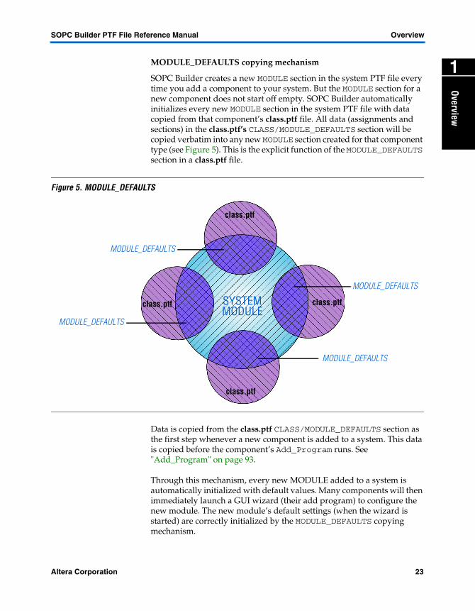
MODULE_DEFAULTS copying mechanismSOPC Builder creates a new MODULE section in the system PTF file every time you add a component to your system. But the MODULE section for a new component does not start off empty. SOPC Builder automatically initializes every new MODULE section in the system PTF file with data copied from that component’s class.ptf file. All data (assignments and sections) in the class.ptf’s CLASS/MODULE_DEFAULTS section will be copied verbatim into any new MODULE section created for that component type (see Figure 5). This is the explicit function of the MODULE_DEFAULTS section in a class.ptf file.
Figure 5. MODULE_DEFAULTS
Data is copied from the class.ptf CLASS/MODULE_DEFAULTS section as the first step whenever a new component is added to a system. This data is copied before the component’s Add_Program runs. See "Add_Program" on page 93.
Through this mechanism, every new MODULE added to a system is automatically initialized with default values. Many components will then immediately launch a GUI wizard (their add program) to configure the new module. The new module’s default settings (when the wizard is started) are correctly initialized by the MODULE_DEFAULTS copying mechanism.
MODULE_DEFAULTS
SYSTEMMODULE
MODULE_DEFAULTS
MODULE_DEFAULTS
MODULE_DEFAULTS
class.ptf
class.ptf
class.ptfclass.ptf
Altera Corporation 23

Overview SOPC Builder PTF File Reference Manual
Where Does MODULE Data Come From?
Data in a MODULE section in the system PTF file gets added and edited at various points in the SOPC Builder process ("SOPC Builder Phase Sequence" on page 26 describes the distinct phases in detail). A MODULE section starts off with initial data copied from the class.ptf’s MODULE_DEFAULTS section. But data (assignments and sections) can be modified, or added, by later phases (during the editing process--and sometimes even during system generation). So: What kind of data comes directly from the class.ptf file (via the MODULE_DEFAULTS copying process) and what data is added later? The answer depends upon the library component.
Fixed Library Components
Some library components are essentially fixed and may have only a few or no parameters. Everything SOPC Builder needs to know about these components: their bus-interface signals, their complete list of I/O ports, their HDL implementation files, etc. is known ahead of time and cannot be edited or changed. Such components can, and probably should, specify every required PTF section and assignment in their class.ptf’s MODULE_DEFAULTS section. This data then gets copied into a system’s PTF file whenever an instance of this component is added. The only per-instance difference between MODULE sections is their given name. The contents of the MODULE sections are copied once by the MODULE_DEFAULTS mechanism and never changed again.
Parameterized Library Components
Some other library components are highly parameterizable. Many of the components’ assignments may not be known until very late in the SOPC Builder generation process. For example, the exact list of I/O pins may not be known until the module’s Generator_Program ("Module Generator Program Phases" on page 30) is finished running. Or, a module’s number of address pins may be editable (e.g., a memory component with configurable size, editable through the wizard). Such modules may start off with a default set of values set by the MODULE_DEFAULTS copying mechanism, but the default data may be modified by a later part of the SOPC Builder process. Some data (for example, port lists) may not be present in the initial MODULE_DEFAULTS contents at all, and will be added later.
For any given component-type, the way the MODULE section data is created depends entirely on the type of component, how heavily parameterized it is, and how the component author (IP developer) chose to implement generation.
24 Altera Corporation

SOPC Builder PTF File Reference Manual Overview
Overview
1
SOPC Builder Design FlowSOPC Builder can be viewed as a tool which takes library components as input and emits assembled systems as output. There are three major steps in this process (see Figure 6).
Figure 6. Steps in the SOPC Builder Design Flow
Component Authoring
IP developers create hardware (RTL, schematics, or EDIF) and software (C-sources, header files, etc.) files which implement an SOPC Builder library component. Sophisticated components may also include an associated GUI, a Generator_Program, and other infrastructure to support automatic or highly-parametric generation. In general, the only SOPC Builder-specific work required to turn an “ordinary” block of IP into an SOPC Builder library component is the creation of a class.ptf file that describes the IP. All library components must have a class.ptf file.
System Assembly
Using the SOPC Builder GUI, a user can create and edit a new system design. This usually involves adding components from the library, configuring the components individually, and editing the overall system configuration (e.g., specifying the address map and master/slave connections). During this phase, the user’s editing activity is recorded in the system PTF file, but (as a rule) no other files are generated or modified.
Component Authoring System Assembly System Generation
SOPC Builder
Altera Corporation 25

Overview SOPC Builder PTF File Reference Manual
System Generation
System Generation starts when the user presses Generate as the final SOPC Builder GUI action, or when the System Generator Program is run from the command line (see "SOPC Builder Design Flow" on page 25). During the System Generation step, many automatic events take place in a well-defined sequence. Ultimately, the result is a set of files which implement for example, HDL files, software-support (SDK) directories, and a simulation project design.
Between the Component Authoring step and the System Assembly step, a user must install one or more library components (and install the SOPC Builder tool). Some library components are included, and installed, with SOPC Builder. Other components are available from Altera and 3rd-party (AMPP) IP partners, and may be installed separately from SOPC Builder.
SOPC Builder Phase Sequence
To discuss what happens in the three steps named, it is useful to divide activity yet further into phases. See Figure 7 on page 27. As a library component author (IP developer) you have the option of specifying what happens to your component during several of these phases. Particular entries in the system PTF file are set and/or used during certain phases. This section describes what activity takes place during each phase. The documentation for each PTF section and assignment specifies when (which phase) the data is used and set. See “PTF File Sections’ on page 63 for information about PTF sections and "PTF Assignments" on page 91 for detailed information on each PTF assignment.
26 Altera Corporation

SOPC Builder PTF File Reference Manual Overview
Overview
1
Figure 7. SOPC Builder Phase SequenceAll of the phases in the System Generation step occur in a fixed, unidirectional sequence. Once started, the System Generation step proceeds through all its phases in order, and does not stop (unless terminated by error or user action).
Development Step Phase
Authoring
Add
Edit
System Configuration
Bind
SDK for CPU 0
...SDK Generation for CPU m
Generator Program for Module 0
Generator Program for Module m
...
Bus Generation
Top Module Generation
Project File Generation
System Assembly
System Generation
Component Authoring
Flow
Done
(Synthesis)
Altera Corporation 27

Overview SOPC Builder PTF File Reference Manual
The phases within the System Assembly step, however, are only loosely ordered. In general, components flow through all four phases in the indicated order (added, configured, and integrated into the system). The System Assembly step is an interactive editing process, so the user can revise a module’s configuration more than once. The System Assembly process always starts with a component being added to the system, but the other three phases (Edit, System Configuration, and Bind) can occur in any order as a result of user-interaction. But, whatever the editing order, the System Assembly step is complete when the user presses the Generate button.
The Component Authoring Phase
Frequently, IP developers wish to take an existing logic-block with a microprocessor bus interface and convert it into an SOPC Builder component. This requires three main steps:
1. Creating a simple text file named class.ptf (often this process can be expedited by copying an existing class.ptf from a similar component and modifying some of the assignment values).
2. Placing all of the files that implement the component (HDL-files, software (.c and .h) support files, etc.) together within one directory, along with the class.ptf file.
3. Copying this directory and its contents into a location on the SOPC Builder library search path, where the name of the destination directory is the same as the formal name of the component.
For commercially available, packaged IP cores, step 3 is often performed by a conventional software-installer (for example, InstallShield®). Creating the installer is part of the work necessary to create fully-packaged IP.
The Add Phase
The Add phase occurs whenever the user adds a new MODULE into his system. The user can double-click on a component’s name in the module pool (library) or press Add or select Add Module from the System menu. When this happens, a new row is added to the module table and the new MODULE is assigned a temporary name.
28 Altera Corporation

SOPC Builder PTF File Reference Manual Overview
Overview
1
A special, one-time action takes place at the beginning of the Add phase. SOPC Builder creates a new MODULE section in the system PTF file. SOPC Builder copies the entire contents of the MODULE_DEFAULTS section from the new component’s class.ptf file into the newly created MODULE section. Thus, an IP core can provide some or all of its Add-phase-required information, even if it has a null Add_Program, by just putting the required information in the MODULE_DEFAULTS section of its class.ptf. For example, if your core will always have a data-bus width of 16 bits, there is no reason to write an Add_Program that sets this value every time in the system PTF file. You can, of course, but it is probably easier just to set this file assignment in the MODULE_DEFAULTS section of the core’s class.ptf file.SOPC Builder then runs the components declared Add_Program, or nothing if the class.ptf specifies no add program (see "Add_Program" on page 93). Of course, SOPC Builder must tell the Add_Program how to find (i.e., the hierarchical path to) the new MODULE section it just created. SOPC Builder provides this information as named command line arguments passed to the Add_Program. A detailed list of these arguments appears in "Appendix A" on page 219 of this document.
Add programs may modify any section or assignment contained within the new MODULE section. This includes, but is not limited to WIZARD_SCRIPT_ARGUMENTS and SYSTEM_BUILDER_INFO sections.
The Edit Phase
Users may or may not edit any of the modules in the system. It is perfectly likely that a module would be configured once, during the Add Phase, and never edited. Most SOPC Builder components, however, provide an editing facility for changing a module's assignments after it has been added to the system.
The Edit-phase occurs whenever a user double-clicks on the row representing a module in the system. If the component has a null Edit_Program assignment in its class.ptf file, no action will take place.
The Edit_Program is called with the same command line arguments as the Add_Program so that it can find the appropriate system PTF file and MODULE section therein to edit. Usually, the Add_Program and Edit_Program provide identical GUIs for configuring the module. Indeed, we've never seen a component which had different add and edit programs.
Edit programs, like add programs, may modify any section or assignment contained in the target MODULE section. This includes, but is not limited to WIZARD_SCRIPT_ARGUMENTS and SYSTEM_BUILDER_INFO sections.
Altera Corporation 29

Overview SOPC Builder PTF File Reference Manual
System Configuration
After at least one component has been added to the system, the user can operate various SOPC Builder GUI controls to modify the system configuration. The address-map table, master/slave patch panel, and even the generation check-boxes on the System Generation tab control the layout, topology, and delivered components for the current system.
Bind Phase
The bind phase used to provide parameterization beyond that of the Add/Edit_Program. Because the binding phase occurs after the system configuration phase, retrospective choices relating to the system’s modules and other elements can be made. Unless the user navigates back to a previous phase, the modules and their inter-connections will not change.
Examples of the types of selections a user might make during the binding phase include: selecting from amongst a list of modules of a given type; selecting interrupt mappings; and other operations which are best made outside of the module’s main wizard due to the uncertainty in ordering with respect to how the user might add different modules.
SDK Generation Phases
See “SDK Generation’ on page 41 for a detailed explanation of SDK Generation.
Module Generator Program Phases
After SDKs have been generated for all appropriate CPU modules (if any), SOPC Builder will go down the list of modules in the system, one by one, and run the Generator_Program for that module.
Any SOPC Builder library component can specify its own Generator_Program in its class.ptf file (see "Generator_Program" on page 135). Modules which do not specify a Generator_Program, or which assign the null value ("") for a Generator_Program, have the Default Generator Program run on their behalf. The Default Generator Program (which is included with SOPC Builder) takes a set of simple, sensible actions required to create a new module from the library component and makes it visible to the system-under-construction, and may be parameterized by the DEFAULT_GENERATOR section of the component's class.ptf.
30 Altera Corporation

SOPC Builder PTF File Reference Manual Overview
Overview
1
Library components which set their Generator_Program assignment explicitly to --none-- will have no action take place during their Module Generation Phase (but this has no effect on how any other module in the system is generated).Module Generator_Programs can be very simple (like the Default Generator Program, which mostly just copies files) or very sophisticated. The HDL implementations of many library components included with SOPC Builder are created directly from their Generator_Programs, not copied from the library. Generator Programs can create highly parameterizable IP. Sometimes, the formal interface (port list) for a module is created by the Generator Program because the ports depend on the module’s parameters in a complex way. It is not uncommon for the Generator_Program to create a module’s PORT_WIRING sections.
Each module’s Generator_Program is executed with a set of command line parameters that indicate the name of the current system, and the name of the MODULE section in that system which is being generated (along with other data). The calling conventions for Generator_Programs are described in "Appendix B" on page 225.
Module Default Generator Program
A special section of the class.ptf named DEFAULT_GENERATOR is reserved for parameterizing the behavior of the Default Generator program. It is not required for the Default Generator to operate, however, as all DEFAULT_GENERATOR assignments have defaults.
This section is only applicable to the Default Generator program. If the Default Generator program is NOT specified in the Generator_Program assignment, then the Default Generator will not run, and the DEFAULT_GENERATOR section of the class.ptf will be ignored.
Default Generator Actions
The Default Generator program generates HDL and performs actions to prepare for system synthesis and place-and-route. The Default Generator makes three distinct actions:
� Generate a renaming wrapper.� Copy implementation files into project directory.� Arrange for some files to be synthesized (if appropriate or asked).
Specific information can be found about each assignment in "PTF Assignments" on page 91.
Altera Corporation 31
Overview SOPC Builder PTF File Reference Manual
Default Generator Makes a Renaming Wrapper
Modules can either be instantiated by the system module directly or they may be black-boxed to hide the details and prevent the simulation tool from finding them. When black_box is set to 1 in the DEFAULT_ GENERATOR section of the class.ptf , the Default Generator program creates a wrapper file that prevents the simulation tool from delving into the underlying HDL. Any files required for synthesis should be listed in the synthesis_files assignment, while those files required for place-and-route, but not for synthesis or simulation, should be listed in the black_box_files assignment.
SOPC Builder needs to know the top-level module name in order to include the component in the system. The name of the top-level module to instantiate is given by the top_module_name assignment in the component’s class.ptf. If this assignment does not exist, SOPC Builder assumes the name of the top-level module matches the component library name.
The Default Generator will make a black box on the component’s behalf, regardless of the black_box setting, for modules defined by .edif files (where an .edif file exists with the top-module name).
Default Generator Copies Files into the Project Directory
The Default Generator program will copy, from the component’s library directory to the current project directory, all files listed in the black_box_files, synthesis_files, verilog_simulation_files, and vhdl_simulation_files assignments.
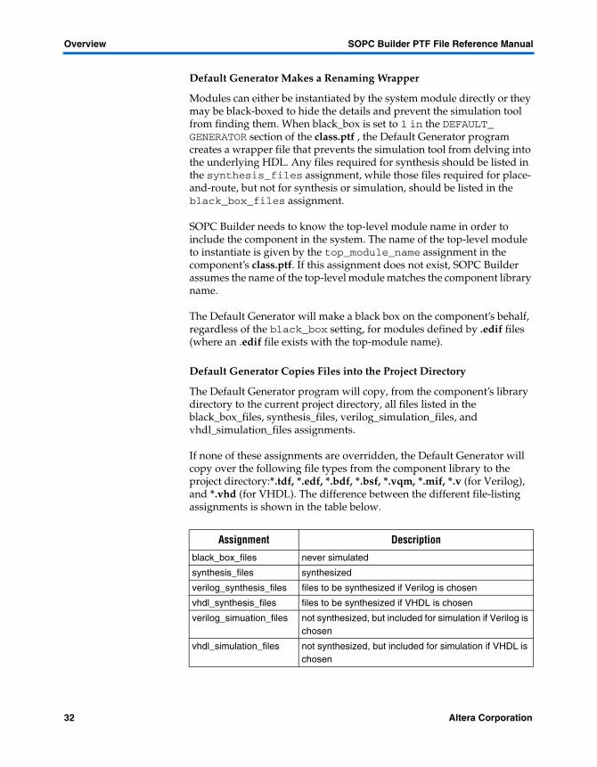
If none of these assignments are overridden, the Default Generator will copy over the following file types from the component library to the project directory:*.tdf, *.edf, *.bdf, *.bsf, *.vqm, *.mif, *.v (for Verilog), and *.vhd (for VHDL). The difference between the different file-listing assignments is shown in the table below.
Assignment Description
black_box_files never simulated
synthesis_files synthesized
verilog_synthesis_files files to be synthesized if Verilog is chosen
vhdl_synthesis_files files to be synthesized if VHDL is chosen
verilog_simuation_files not synthesized, but included for simulation if Verilog is chosen
vhdl_simulation_files not synthesized, but included for simulation if VHDL is chosen
32 Altera Corporation

SOPC Builder PTF File Reference Manual Overview
Overview
1
Default Generator Arranges for SynthesisAll files listed in the synthesis_files assignment will be synthesized by the Quartus® II software. The Default Generator accomplishes this by copying the synthesis_files list (as well as the language-specific verilog_synthesis_files or vhdl_synthesis_files) into the module’s Synthesis_HDL_Files assignment.
The Bus Generation Phase
SOPC Builder generates plain text HDL code (either VHDL or Verilog) for all of the bus-interconnect logic in the system. A complete system PTF file contains enough information to build the address-decoders, databus- multiplexers, arbiters (for shared slaves), interrupt logic, and bus-timing logic for every master and slave in the system.
Figure 8. System with Master Modules
System S
ZYX
B CA
m2m1mm
sss
Library Component
automatically generated"arbitration" Module
Altera Corporation 33

Overview SOPC Builder PTF File Reference Manual
Future versions of SOPC Builder reserve the right to implement the bus-interconnect logic in any manner which agrees with the Avalon–Bus Specification or the AMBA–AHB Specification from the point of view of any master or slave interface. Component authors should not rely on any particular implementation of the bus logic— but they may rely on the interface agreeing with the specification. Figure 8 shows one internal implementation of the bus logic for an example system at a very high level.
Consider a system S with three master-modules X, Y, and Z. Assume X and Y each have one master-interface named m. Assume Z has two master-interfaces named m1 and m2. The system also has three slaves, A, B, and C, each with a single slave port s. The user created this system by creating a new system named S and adding modules X, Y, Z, A, B, and C. The user then configured the system to decide which masters can access which slaves (details of the arbitrary arrangement depicted in the figure are not important to this discussion).
The current implementation of SOPC Builder creates a separate bus-logic module "next to" (connected directly to) each master- or slave-port on each module. These bus-logic modules are called arbitration modules, whether or not they actually contain an arbiter. The system in this example would have 7 arbitration modules, one "next to" each master/slave port on each module. The generated logic in these modules is guaranteed to present each master or slave interface with a well-formed set of signals and protocols.
f See the Avalon Bus Specification Reference Manual at http://www.altera.com/literature/lit-nio.html for further signal and protocol details.
All HDL-code which implements the bus-logic is written into the system's HDL file. This is a file with the same name as the system being generated. Suppose the user was generating a system named fan_control_processor in VHDL. In this example, all of the bus-generation logic (and the arbitration modules) would be written to a file named fan_control_processor.vhd. More content is added to the system HDL file during the Top-Module Generation phase. No changes are made to the system PTF file during the Bus Generation Phase.
34 Altera Corporation

SOPC Builder PTF File Reference Manual Overview
Overview
1
The Top-Module Generation PhaseDuring the Top-Module Generation phase, SOPC Builder writes the definition of the system’s top-module into the system HDL file. The top-module definition includes proper declaration of all the system’s I/O ports, instances of every module in the system, instances of all the arbitration modules that contain the bus logic, and interconnections between all the modules.
SOPC Builder also defines a test-bench module (always named test_bench) in the system HDL file. The test-bench contains exactly one instance of the system module (with the instance-name DUT), and a stimulus source for the system’s clock and reset inputs. SOPC Builder also creates a schematic symbol (.bsf) file so that the system module can be used within Quartus’ block-diagram editor.
The Project File Generation Phase
In addition to the hardware (HDL) and software (SDK) files generated during the preceding phases, SOPC Builder also creates files and directories to control and support third-party tools.
Synthesis-Control Files
In the past, SOPC Builder used Leonardo Spectrum as the synthesis tool and controlled it through the tool-control file. SOPC Builder now relies on Quartus II software synthesis to build the system. All synthesis settings should be set inside the Quartus II software tool.
Simulation Project Generation
SOPC Builder creates a ModelSim project directory for rapidly simulating the generated system. The system HDL file itself (written out during the Top-Module Generation phase) already contains a test-bench module (see "The Top-Module Generation Phase" on page 35). During the Project Generation Phase, SOPC Builder creates a simulation directory; <system_name>_sim/
SOPC Builder generates the following files in this directory:
� Memory-initialization files for any MODULE that has a CONTENTS section (See “SYSTEM <system_name>/MODULE<module_name>/ WIZARD_SCRIPT_ARGUMENTS/CONTENTS srec” on page 67.)
Altera Corporation 35

Overview SOPC Builder PTF File Reference Manual
� A ModelSim® Project file named <system_name>_sim.mpf. For example, when the user opens this file in ModelSim (by double-clicking the file icon), the system-specific simulation project is loaded into the tool.
� A.do-file (ModelSim command-script file) called create_<system_name>_project.do. This file contains ModelSim commands which allow the user to recreate the ModelSim project file (above) if needed. This .do file is seldom used directly—it is mainly provided for reference so the exact commands used to provide the command file are available for expert users' reference.
� A startup command file named modelsim.tcl which contains commands that get executed whenever the user opens the project file. The startup script is automatically executed when the project is opened— no user action is required. The modelsim.tcl startup script performs only one command: it runs the script setup_sim.do.
� A file called setup_sim.do which defines system-specific macros which are handy for manipulating the generated system design from within the simulator. The list of defined macros is displayed in a banner message when this script is run. The user can, of course, edit this file (or copy-and-modify it) to extend, change, or add his own macros.
� A file called virtuals.do which defines virtual signal types. Any MODULE in the system can add its own virtual signal types by including a SIMULATION/DISPLAY/TYPES section (see "SYSTEM <system_name>/MODULE <module_name>/ SIMULATION/ DISPLAY" on page 80). ModelSim can display virtual signal types in the waveform window with special labels and/or formatting. For example, the Nios CPU defines a virtual signal type which allows the instruction-bus to be disassembled and displayed as instruction mnemonics. The virtuals.do script is automatically loaded by the load simulation (s) macro.
� A file called wave_presets.do which contains a set of commands that open and configure a waveform display window. This window will display waveforms that each MODULE has declared as interesting via its SIMULATION/DISPLAY/SIGNAL sections (see "SYSTEM <system_name>/MODULE <module_name>/ SIMULATION/DISPLAY/ SIGNAL <alphabetical index>" on page 82). The wave_presets.do file is linked to the defined w macro.
36 Altera Corporation

SOPC Builder PTF File Reference Manual Overview
Overview
1
Command Line System Generation ScriptDuring the Project File Generation phase, SOPC Builder creates a file name <system_name>_generation_script (no dot). This is a shell command-script which can be executed from the command line, from another script, or executed by a program. This script will rerun the System Generation step and recreate the system—without running the System Assembly (GUI) step. This command script can be used as a scriptable part of a larger design's build–or–make process.
Quartus II Software Synthesis
SOPC Builder only generates an HDL description of the system module for a given Altera part. No synthesis of the system is performed by SOPC Builder. For synthesis and compilation, a user should use the Quartus II software tool.
Some IP developers may, however, wish to deliver pre-synthesized, or non-synthesizable hardware implementations. These authors should package their logic in a synthesizable HDL "wrapper" which instantiates the "real" core as a black-box.
Component authors who use the Default Generator Program can request this service by setting the DEFAULT_GENERATOR/black_box assignment to 1 (See "CLASS <class_name>/DEFAULT_GENERATOR" on page 64 for details about this section and "black_box" on page 102 for detailed assignment information.) When the black_box assignment is set, the default generator program will automatically create a wrapper that instantiates the IP's "real" core-logic as a black box.
PTF Files PTF files are human-readable, human-editable ASCII-text databases of information about SOPC Builder library components and systems. SOPC Builder creates a PTF file to store design data when a system is created. Also, each SOPC Builder library component is described by (and discovered from) a PTF file.
The SOPC Builder GUI is really a system PTF file editor. Advanced users may wish to edit a system PTF file using a standard text editor. Manual PTF editing is entirely supported, but you should be careful to close the SOPC Builder GUI before opening a system PTF file in a text editor. As always, you may get unpredictable results if you open the same file in two editors at the same time—one editor being the SOPC Builder GUI.
PTF Syntax Described
A formal BNF syntax definition for PTF files can be found at "Appendix C" on page 217.
Altera Corporation 37
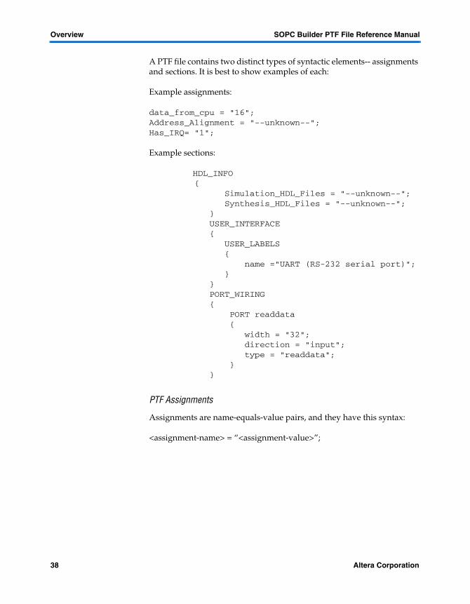
Overview SOPC Builder PTF File Reference Manual
A PTF file contains two distinct types of syntactic elements-- assignments and sections. It is best to show examples of each:
Example assignments:
data_from_cpu = "16";Address_Alignment = "--unknown--";Has_IRQ= "1";
Example sections:
HDL_INFO {
Simulation_HDL_Files = "--unknown--"; Synthesis_HDL_Files = "--unknown--"; } USER_INTERFACE { USER_LABELS { name ="UART (RS-232 serial port)"; } } PORT_WIRING { PORT readdata { width = "32"; direction = "input"; type = "readdata"; } }
PTF Assignments
Assignments are name-equals-value pairs, and they have this syntax:
<assignment-name> = “<assignment-value>”;
38 Altera Corporation

SOPC Builder PTF File Reference Manual Overview
Overview
1
Assignment names may be of arbitrary length, and may contain any alphanumeric character (upper and lower case), as well as underscore (“_”) forward-slashes (“/”) and dollar-signs (“$”). Assignment names may not contain spaces or any other punctuation characters. Assignment values are always enclosed by paired double-quotation marks. Assignment values may contain any ASCII character within the surrounding quotation marks. If an assignment value contains a double-quote (“), the double-quote must be preceded by a backslash (“\”). All assignments end in a semicolon. White space (including new lines) are ignored in PTF files (except in quoted assignment-values, of course.)PTF Sections
Sections are groupings of other PTF elements, and they have this syntax:
<section-type> <optional-section-name> { <section-body> }
Section-type and section-name fields each obey the same restrictions as assignment names, above (alphanumeric only, no spaces or punctuation, etc.). The Section Name is optional for PTF file syntax; however SOPC Builder requires certain sections (e.g., PORT) to have a name. Every section must have a curly-brace pair “{}” enclosing a section-body. The section-body can be null (contain no characters). In general, a section body can contain an arbitrary number of assignments, and an arbitrary number of sections. Because sections can contain sections, PTF files are hierarchical. Indentation is often used to make their contents more human-readable (but, being white space, indentation is formally ignored).
When documents refer to a particular sub-section in a PTF file, it is conventional to use a “/” (forward-slash) hierarchy separator (even though such a reference is neither recognized nor required by PTF file syntax). So, when this document wants to refer to, for example, a MODULE section named my_module within the SYSTEM section, it would use this notation:
SYSTEM/MODULE my_module/...
Altera Corporation 39

Overview SOPC Builder PTF File Reference Manual
Recognized and Unrecognized Data
This document describes all PTF assignments and sections which are recognized by SOPC Builder. When you create or edit a PTF file, you may add your own assignments and sections. For example, you may need new assignments and sections for storing IP-specific parameters which control how your component is generated. SOPC Builder simply ignores any unrecognized assignments or sections. You are, of course, free to write your own generator program which reads and understands these settings. In principle, you can add IP-specific assignments anywhere in the system PTF file, although there are special designated sections conventionally used for storing IP-specific parameters. All PTF contents, whether recognized or not, must be syntactically correct.
The Current Project Directory
For conventional library components, the files that define the simulation and synthesis models of a module (i.e., the HDL-implementation of that module) are either copied-into or generated-in the current project directory. Thus, for most SOPC Builder systems, all of the HDL files for that system reside within the same project directory.
All filenames that occur anywhere in the PTF file (including file lists that appear in simulation and synthesis assignments) are subject to the following substitution: the string:
__PROJECT_DIRECTORY__ (two leading/trailing underscores)
occurring anywhere in any PTF file value is replaced by the path to the current SOPC Builder project directory (usually the same as the current Quartus project directory). This substitution supports two features:
1. SOPC Builder systems and projects are portable. If an entire SOPC Builder project is copied or moved to another directory, the project will behave as expected. Because the actual name of the project-directory never appears in the PTF file (the name is substituted at run time) SOPC Builder will be able to use the PTF file no matter where it resides.
2. Component authors can often specify synthesis files and simulation files during the Component Authoring step when the project directory is not known. A library component could be used in any number of systems residing in directories created by the user. By using the token __PROJECT_DIRECTORY__, the component author can refer to files in the system’s project directory no matter where the system is actually generated later.
40 Altera Corporation

SOPC Builder PTF File Reference Manual Overview
Overview
1
How are Top-Level I/O Ports Named?Ports will be renamed to avoid name space conflicts. Consider the following system.
SYSTEM consider_this { ... MODULE uart_1 { ... SYSTEM_BUILDER_INFO { ... Instantiate_In_System_Module = "1"; } PORT_WIRING { PORT txd { width = "1"; direction = "output"; } PORT rxd { width = "1"; direction = "input"; } } } MODULE uart_2 { ... SYSTEM_BUILDER_INFO { ... Instantiate_In_System_Module = "1"; } PORT_WIRING { PORT txd { width = "1"; direction = "output"; } PORT rxd { width = "1"; direction = "input"; } } } ...
Altera Corporation 41

Overview SOPC Builder PTF File Reference Manual
}
This system contains two UARTs. Each UART is instantiated within the system module and each has a txd pin and a rxd pin. Clearly, the user does not wish both UARTS to drive the same txd pin, or receive data from the same rxd pin. To avoid such contention, the System Generator Program will instantiate uart_1 and uart_2 with different names for each uart txd and rxd pins. If the system were to be generated in verilog, uart1 and uart2 would be instantiated inside the system module with the following port redirection.
uart1 the_uart1 ( ... .rxd (rxd_to_the_uart1), .txd (txd_from_the_uart1), );
uart2 the_uart2 ( ... .rxd (rxd_to_the_uart2), .txd (txd_from_the_uart2), );
There are four types of ports in the system module. Each port has its own naming scheme. The types are:
1. Global port inputs: for example, ports of type clk and clk_*.
2. Unshared ports to modules that are instantiated outside of the system module: for example, the readdata port from external user logic.
3. Shared ports to modules that are ports to modules that are instantiated outside of the system module: for example, a shared tri-state databus which wires to off-chip components.
4. Non-system bus ports that wire to/from modules instantiated inside the system: for example, the txd and rxd pins from the UART mentioned above.
Global Port Inputs
Currently, the only global ports are ports of type clk.Each of these ports will connect to the global input port named clk.
42 Altera Corporation
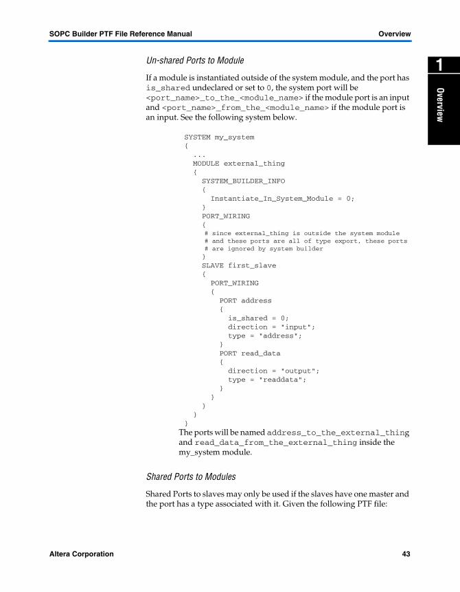
SOPC Builder PTF File Reference Manual Overview
Overview
1
Un-shared Ports to ModuleIf a module is instantiated outside of the system module, and the port has is_shared undeclared or set to 0, the system port will be <port_name>_to_the_<module_name> if the module port is an input and <port_name>_from_the_<module_name> if the module port is an input. See the following system below.
SYSTEM my_system { ... MODULE external_thing { SYSTEM_BUILDER_INFO { Instantiate_In_System_Module = 0; } PORT_WIRING { # since external_thing is outside the system module
# and these ports are all of type export, these ports# are ignored by system builder
} SLAVE first_slave { PORT_WIRING { PORT address { is_shared = 0; direction = "input"; type = "address"; } PORT read_data { direction = "output"; type = "readdata"; } } } } }
The ports will be named address_to_the_external_thing and read_data_from_the_external_thing inside the my_system module.
Shared Ports to Modules
Shared Ports to slaves may only be used if the slaves have one master and the port has a type associated with it. Given the following PTF file:
Altera Corporation 43

Overview SOPC Builder PTF File Reference Manual
SYSTEM my_system { MODULE ram { SYSTEM_BUILDER_INFO { Instantiate_In_System_Module = "0"; } Slave ram_slave { PORT_WIRING { PORT ram_address { type = "address"; width = 4; direction = "input"; is_shared = "1"; } PORT ram_write_n { type = "write_n"; width = 1; direction = "input"; is_shared = "1"; } ... } SYSTEM_BUILDER_INFO { MASTERED_BY cpu/data_master { ... } } } } ... }
ram_address will be represented by the signal cpu_address. Active low signals such as ram_write_n will have the _n truncated to n for backwards compatibility with SOPC Builders earlier than version 2.5. (for example, the signal which represents ram_write_n is cpu_writen not cpu_write_n).
Non-System Bus Ports
Works just like the UART example above. The only addition is ports with direction inout are named
44 Altera Corporation

SOPC Builder PTF File Reference Manual Overview
Overview
1
<port_name>_to_and_from_the_<module_name>.Walk-through examples
Simple Example (non-parameterized component)
This section looks at the changes which occur to the system.ptf when a simple component is added and generated. This example starts with the System PTF file and add a component named write_only which is described by the following PTF file.
CLASS write_only{ USER_INTERFACE { USER_LABELS { name = "simple peripheral"; } } MODULE_DEFAULTS { class = "write_only"; class_version = "2.0"; SLAVE s1 { PORT_WIRING { PORT writedata { width = "8"; direction = "input"; type = "writedata"; } PORT write { width = "1"; direction = "input"; type = "write"; } } SYSTEM_BUILDER_INFO { Bus_Type = "avalon"; Address_Width = "0"; Data_Width = "8"; Has_IRQ = "0"; Base_Address = "--unknown--"; } } PORT_WIRING { PORT out {
Altera Corporation 45

Overview SOPC Builder PTF File Reference Manual
width = "8"; direction = "output"; } } SYSTEM_BUILDER_INFO { Instantiate_In_System_Module = "1"; Is_Enabled = "1"; Address_Width = "4"; } }}
When the user uses the GUI to add this component to his system, the GUI first creates a new MODULE section with an exclusive name. For example, write_only_0.The system PTF file now looks like:
SYSTEM my_system{ ... MODULE write_only_0 { } ...}
The GUI then calls the Add_Program specified by CLASS write_only/ASSOCIATED_FILES/Add_Program. Since no Add_Program is specified, the default add program is run. The default add program simply takes everything in CLASS write_only/MODULE_DEFAULTS and copies it to the MODULE write_only_0 section. The system PTF now looks like.
SYSTEM my_system{ ... MODULE write_only_0 { class = "write_only"; class_version = "2.0"; SLAVE s1 { PORT_WIRING { PORT writedata { width = "8"; direction = "input"; type = "writedata"; } PORT write
46 Altera Corporation
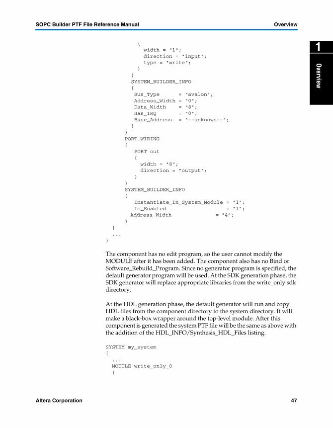
SOPC Builder PTF File Reference Manual Overview
Overview
1
{ width = "1"; direction = "input"; type = "write"; } } SYSTEM_BUILDER_INFO { Bus_Type = "avalon"; Address_Width = "0"; Data_Width = "8"; Has_IRQ = "0"; Base_Address = "--unknown--"; } } PORT_WIRING { PORT out { width = "8"; direction = "output"; } } SYSTEM_BUILDER_INFO { Instantiate_In_System_Module = "1"; Is_Enabled = "1"; Address_Width = "4"; } } ...}The component has no edit program, so the user cannot modify the MODULE after it has been added. The component also has no Bind or Software_Rebuild_Program. Since no generator program is specified, the default generator program will be used. At the SDK generation phase, the SDK generator will replace appropriate libraries from the write_only sdk directory.
At the HDL generation phase, the default generator will run and copy HDL files from the component directory to the system directory. It will make a black-box wrapper around the top-level module. After this component is generated the system PTF file will be the same as above with the addition of the HDL_INFO/Synthesis_HDL_Files listing.
SYSTEM my_system{ ... MODULE write_only_0 {
Altera Corporation 47

Overview SOPC Builder PTF File Reference Manual
class = "write_only"; class_version = "2.0"; HDL_INFO { Synthesis_HDL_Files = "write_only_module.bb.v"; } SLAVE s1 { PORT_WIRING { PORT writedata { width = "8"; direction = "input"; type = "writedata"; } PORT write { width = "1"; direction = "input"; type = "write"; } } SYSTEM_BUILDER_INFO { Bus_Type = "avalon"; Address_Width = "0"; Data_Width = "8"; Has_IRQ = "0"; Base_Address = "--unknown--"; } } PORT_WIRING { PORT out { width = "8"; direction = "output"; } } SYSTEM_BUILDER_INFO { Instantiate_In_System_Module = "1"; Is_Enabled = "1"; Address_Width = "4"; } } ...}
48 Altera Corporation

SOPC Builder PTF File Reference Manual Overview
Overview
1
Complex Example (Highly-Parameterized) ComponentThis example looks at the changes which occur to the system.ptf file when a component with complexity is added/edited and generated. In this example, assume a system PTF file with some contents as shown below:
SYSTEM my_system{ ...}
Continuing with the example, the following component file containing some other contents is incorporated into the system.ptf file as shown below:
CLASS optional_irq{ ASSOCIATED_FILES { Add_Program = "optional.jar"; Edit_Program = "optional.jar"; Generator_Program = "mk_optional.pl"; } MODULE_DEFAULTS { class = "optional_irq"; class_version = "2.0"; SLAVE s1 { SYSTEM_BUILDER_INFO
} Bus_Type = "avalon";
Address_Alignment = "native"; Address_Width = "3"; Data_Width = "16"; Has_IRQ = "0";}
PORT_WIRING { ... } SYSTEM_BUILDER_INFO { Instantiate_In_System_Module = "1"; Is_Enabled = "1"; } WIZARD_SCRIPT_ARGUMENTS { do_optional_irq = "0"; } }}
Altera Corporation 49

Overview SOPC Builder PTF File Reference Manual
When the user uses the SOPC GUI to add this component to his system, the GUI first creates a new MODULE section with an exclusive name. For example, optional_irq_0.The system PTF file now looks like:
SYSTEM my_system{ ... MODULE write_only_0 { } ...}
The SOPC_BUILDER GUI then takes everything in CLASS/write_only/MODULE_DEFAULTS and copies it to the MODULE section. The system PTF file now looks like:
SYSTEM my_system{ ... MODULE optional_irq_0 { class = "optional_irq"; class_version = "2.0"; SLAVE s1 { SYSTEM_BUILDER_INFO
{ Bus_Type = "avalon";
Address_Alignment = "native"; Address_Width = "3"; Data_Width = "16"; Has_IRQ = "0";}
} PORT_WIRING { ... } SYSTEM_BUILDER_INFO { Instantiate_In_System_Module = "1"; Is_Enabled = "1"; } WIZARD_SCRIPT_ARGUMENTS { do_optional_irq = "0"; } } ...}
50 Altera Corporation
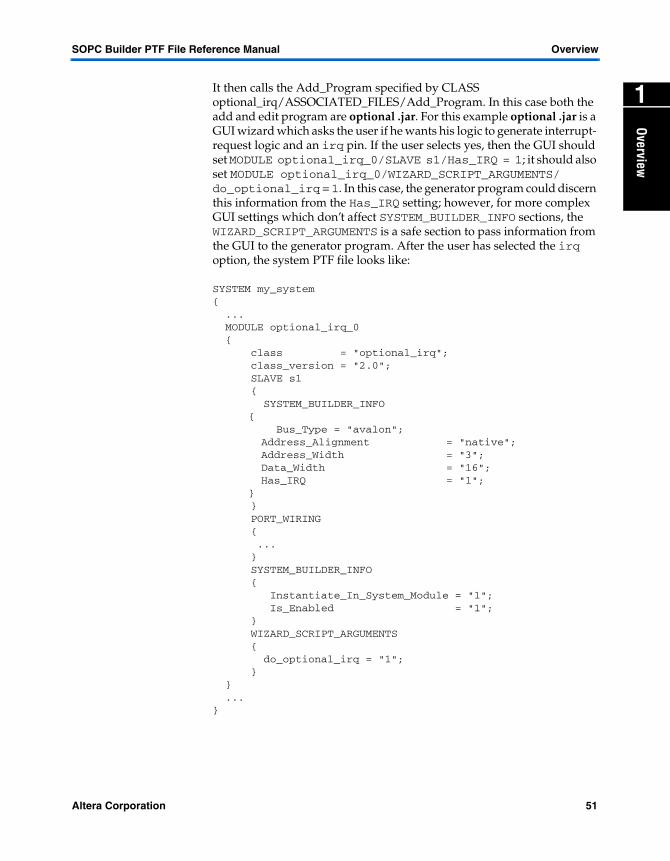
SOPC Builder PTF File Reference Manual Overview
Overview
1
It then calls the Add_Program specified by CLASS optional_irq/ASSOCIATED_FILES/Add_Program. In this case both the add and edit program are optional .jar. For this example optional .jar is a GUI wizard which asks the user if he wants his logic to generate interrupt- request logic and an irq pin. If the user selects yes, then the GUI should set MODULE optional_irq_0/SLAVE s1/Has_IRQ = 1; it should also set MODULE optional_irq_0/WIZARD_SCRIPT_ARGUMENTS/ do_optional_irq = 1. In this case, the generator program could discern this information from the Has_IRQ setting; however, for more complex GUI settings which don’t affect SYSTEM_BUILDER_INFO sections, the WIZARD_SCRIPT_ARGUMENTS is a safe section to pass information from the GUI to the generator program. After the user has selected the irq option, the system PTF file looks like:SYSTEM my_system{ ... MODULE optional_irq_0 { class = "optional_irq"; class_version = "2.0"; SLAVE s1 { SYSTEM_BUILDER_INFO
{ Bus_Type = "avalon";
Address_Alignment = "native"; Address_Width = "3"; Data_Width = "16"; Has_IRQ = "1";}
} PORT_WIRING { ... } SYSTEM_BUILDER_INFO { Instantiate_In_System_Module = "1"; Is_Enabled = "1"; } WIZARD_SCRIPT_ARGUMENTS { do_optional_irq = "1"; } } ...}
Altera Corporation 51

Overview SOPC Builder PTF File Reference Manual
The component has the same edit program as its add program, so a user could change his mind later and decide that he didn’t want the optional irq. This component has no bind or software generator program, so no other actions will affect this MODULE (other than SOPC GUI renaming/deleting the module) until generation time.
At the SDK generation phase, the SDK generator will replace appropriate libraries from the optional_irq sdk directory. At the HDL generation phase, the CLASS optional_irq/ ASSOCIATED_FILES/Generator_Program mk_optional.pl will be called with the parameters discussed in "Appendix B" on page 225. For this example, the mk_optional.pl looks at the do_optional_irq setting and creates appropriate logic. The script will write the hdl file created to the HDL_INFO section. If do_optional_irq is set, the generator program will also add an irq port to the SLAVE s1 PORT_WIRING section. After the generator program is done, the system PTF file will look like:
SYSTEM my_system{ ... MODULE optional_irq_0 { class = "optional_irq"; class_version = "2.0"; HDL_INFO { Synthesis_HDL_Files = "optional_irq_0.vhd"; } SLAVE s1 { SYSTEM_BUILDER_INFO
{ Bus_Type = "avalon";
Address_Alignment = "native"; Address_Width = "3"; Data_Width = "16"; Has_IRQ = "1";}
} PORT_WIRING { ... PORT option { width = "1"; direction = "input"; type = "irq"; } } SYSTEM_BUILDER_INFO {
52 Altera Corporation

SOPC Builder PTF File Reference Manual Overview
Overview
1
Instantiate_In_System_Module = "1"; Is_Enabled = "1"; } WIZARD_SCRIPT_ARGUMENTS { do_optional_irq = "1"; } } ...}Altera Corporation 53


Altera Corporation
O
1
SDK Generation
verviewIntroduction SOPC Builder provides support for the Altera Excalibur device family. This support includes facilities to generate an SDK directory, similar to the one generated for Nios CPU’s under SOPC Builder. The PTF description files are for both CPU components and peripheral components, allowing SDK code for either platform-specific or platform-agnostic development. Also, SOPC Builder generalizes some of the target runtime support that was present in the Nios libraries to handle different CPUs and different UARTs (or other communication channels).
SDK Generation
For reference, here is a very brief summary of the steps taken by SOPC Builder to construct an SDK for each CPU, at system generation time. This is performed by a script called mk_custom_sdk.
For each CPU in the system, and each supported toolchain of that CPU
Create an SDK directory named <cpu_name>[_<toolchain>]_sdkCreate SDK subdirectories inc, lib, and srcExamine the CPU component’s class.ptf file, and
Do1.Add any prototypes and structs to excalibur.h2. Add any library files to lib3.Add any example source code files to src4.Add any additional include files to inc
For each peripheral in the system, if mastered by the CPU. Examine the peripheral’s class.ptf file, and. Do
1.Add the base address and IRQ number to excalibur.h 2.Add the base address and IRQ number to excalibur.s3.Add any prototypes and structs to excalibur.h4.Add any library files to lib5.Add any example source code files to src6.Add any additional include files to inc
Create final excalibur.h and excalibur.s files in incCreate and use Makefile in the lib directory that builds everything
in libOptionally create a Tcl script to support Quartus Software Mode
56

SDK Generation SOPC Builder PTF File Reference Manual
PTF Entries for Peripherals
This section describes the PTF entries for SOPC Builder compatible peripherals to control the generation of a target SDK, for one or more kind of CPU.
Example From altera_avalon_uart
The following listing is an excerpt from the class.ptf file which describes the altera_avalon_uart component to SOPC Builder.
Code Example : altera_avalon_uart Component
CLASS altera_avalon_uart{ SDK_GENERATION { SDK_FILES 0 { cpu_architecture = "always"; printf_txchar_routine = "nr_uart_txchar"; printf_rxchar_routine = "nr_uart_rxchar"; } SDK_FILES 1 { cpu_architecture = "nios"; c_structure_type = "np_uart *"; short_type = "uart"; c_header_file = "sdk/uart_struct.h"; asm_header_file = "sdk/uart_struct.s"; sdk_files_dir = "sdk"; } SDK_FILES 2 { cpu_architecture = "arm922t"; c_structure_type = "np_uart *"; short_type = "uart"; c_header_file = "sdk/uart_struct.h"; sdk_files_dir = "sdk_arm"; } SDK_FILES 3 { cpu_architecture = "arm922t"; toolchain = "gnu"; asm_header_file = "sdk/uart_struct.s"; } }…}
57 Altera Corporation

SOPC Builder PTF File Reference Manual SDK Generation
Overview
1
This peripheral divides is SDK-related assignments into four sections, named SDK_FILES 0 through SDK_FILES 3. The section names 0 through 3 are arbitrary; they merely need to be unique strings from each other. The section SDK_FILES 0 gives settings that apply to the UART as used by any CPU. Specifically, the names of its character I/O routines are given. (Elsewhere in the class.ptf, the Is_Printable_Device assignment is set to 1.)The section SDK_FILES 1 is used only by the Nios CPU, because of the assignment cpu_architecture = “nios”;. Other assignments in this section refer to Nios assembly language files which implement routines for the UART.
The section SDK_FILES 2 is used only by the ARM922T CPU, and the section SDK_FILES 3 is also used only by the ARM922T CPU, and, even more specifically, only by the SDK built for the GNU toolchain. (The Excalibur device support in SOPC Builder actually creates separate SDKs for each of the available toolchains, ADS and GNU.)
General Layout
To control the SDK generation for your peripheral, you must include an SDK_GENERATION section within the CLASS section.
The SDK_GENERATION section in turn contains one or more SDK_FILES sections, each with a unique but ignored name.
Filtering By CPU And Toolchain
Each SDK_FILES section contains assignments which may apply to a particular CPU, or all CPUs. Furthermore, the assignments may apply only to a particular toolchain. (At present, CPUs must support the GNU toolchain; the Excalibur device support is unique and idiosyncratic in that it supports another toolchain called ADS.)
The cpu_architecture assignment specifies which CPUs an SDK_FILES section applies to. The value of the cpu_architecture assignment matches if it is a substring of the CPU_Architecture assignment (CLASS/MODULE_DEFAULTS/-WIZARD_SCRIPT_ARGUMENTS/CPU_Architecture) of a particular CPU. This means that a cpu_architecture value of “nios” will match both nios_16 and nios_32.
Altera Corporation 58
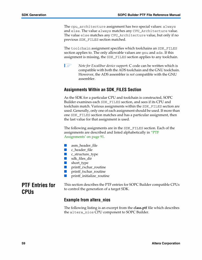
SDK Generation SOPC Builder PTF File Reference Manual
The cpu_architecture assignment has two special values: always and else. The value always matches any CPU_Architecture value. The value else matches any CPU_Architecture value, but only if no previous SDK_FILES section matched.
The toolchain assignment specifies which toolchains an SDK_FILES section applies to. The only allowable values are gnu and ads. If this assignment is missing, the SDK_FILES section applies to any toolchain.
1 Note for Excalibur device support: C code can be written which is compatible with both the ADS toolchain and the GNU toolchain. However, the ADS assembler is not compatible with the GNU assembler.
Assignments Within an SDK_FILES Section
As the SDK for a particular CPU and toolchain is constructed, SOPC Builder examines each SDK_FILES section, and sees if its CPU and toolchain match. Various assignments within the SDK_FILES section are used. Generally, only one of each assignment should be used. If more than one SDK_FILES section matches and has a particular assignment, then the last value for that assignment is used.
The following assignments are in the SDK_FILES section. Each of the assignments are described and listed alphabetically in “PTF Assignments’ on page 91.
� asm_header_file � c_header_file � c_structure_type� sdk_files_dir� short_type� printf_rxchar_routine � printf_txchar_routine� printf_initialize_routine
PTF Entries for CPUs
This section describes the PTF entries for SOPC Builder compatible CPUs to control the generation of a target SDK.
Example from altera_nios
The following listing is an excerpt from the class.ptf file which describes the altera_nios CPU component to SOPC Builder.
59 Altera Corporation

SOPC Builder PTF File Reference Manual SDK Generation
Overview
1
Code Example: altera_nios_CPU componentCLASS altera_nios_time_limited{ SDK_GENERATION { CPU { gnu_tools_prefix = "nios-elf"; sdk_directory_suffix = "sdk"; program_prefix_file = "nios_jumptostart.s.o"; test_code_prefix_file = "nios_jumptostart.s.o"; QUARTUS_TCL_SCRIPT { toolchain = "gnu"; cpu_architecture = "nios_32"; exclude_lib_files = "nios_germs_monitor.s+nios_gdb_ standalone.c"; SWB_ASSIGNMENT 4 { name = "BYTE_ORDER"; value = "LITTLE ENDIAN"; } SWB_ASSIGNMENT 7 { name = "GNUPRO_NIOS_ASM_COMMAND_LINE"; value = "-I. –I %sdk_directory%/inc –I %sdk_directory%/lib –I
%sdk_directory%/src --defsym __nios32__=1"; } SWB_ASSIGNMENT 8 { name = "GNUPRO_NIOS_CPP_COMMAND_LINE"; value = "-g -I. -I%sdk_directory%/inc -I%sdk_directory%/lib –I
sdk_directory%/src -D__nios32__=1"; } SWB_ASSIGNMENT 9 { name = "GNUPRO_NIOS_LINK_COMMAND_LINE"; value = "-g -L %sopc_directory%/bin/nios-gnupro/nios-elf/lib/m32-L
%sopc_directory%/bin/nios-gnupro/lib/gcc-lib/nios-elf/%gcc_version%/m32 –lm –lc -lgcc -T %sopc_directory%/bin/excalibur.ld";
} SWB_ASSIGNMENT 10 { name = "OUTPUT_FILE_NAME"; value = "Debug/%projectname%_application.srec"; } SWB_ASSIGNMENT 14 { name = "TOOLSET"; value = "GNUPro for Nios"; } } SDK_FILES { … } … } … } … }…}
Altera Corporation 60

SDK Generation SOPC Builder PTF File Reference Manual
A CPU class.ptf file has the same sections as a peripheral, with the addition of a CPU section within the SDK_GENERATION section. The CPU section contains several assignments, and, optionally, a QUARTUS_TCL_SCRIPT section to provide Tcl script support for Quartus’s Software Mode.
General Layout
To control the SDK generation for your CPU, you must include an SDK_GENERATION section within the CLASS section.
The SDK_GENERATION section in turn contains one ore more SDK_FILES sections, each with a unique but ignored name. Optionally, a QUARTUS_TCL_SCRIPT section may be present, to control the generation of a Tcl script which can be used to set up Quartus Software Mode.
The SDK_FILES sections for a CPU are treated identically to the SDK_FILES sections for a peripheral. (Clearly, the cpu_architecture assignment is only meaningful for a CPU component which can produce more than one CPU architecture; the Nios component can be either a nios_16 or a nios_32.)
Assignments Within the CPU Section
The assignments with the CPU section are global settings for this CPU’s SDK. Each of the assignments are described and listed alphabetically in “PTF Assignments’ on page 91.
� gnu_tools_prefix � program_prefix_file� sdk_directory_suffix � test_code_prefix_file
The QUARTUS_TCL_SCRIPT Section
You may optionally include a QUARTUS_TCL_SCRIPT section within your CPU section, to support Quartus Software Mode. If this section is present, SOPC Builder will construct a Tcl script which sets up a Quartus Software Mode project with all library files and header files, and not source files. The QUARTUS_TCL_SCRIPT section describes the various necessary settings that the Tcl script must ensure for a particular CPU and toolchain.
The following assignments and sections may be present in a QUARTUS_TCL_SCRIPT section. Each of the assignments are described and listed alphabetically in “PTF Assignments’ on page 91.
61 Altera Corporation

SOPC Builder PTF File Reference Manual SDK Generation
Overview
1
� cpu_architecture� exclude_lib_files� toolchainSWB_ASSIGNMENTS
Any number of SWB_ASSIGNMENT sections may be present. Each SWB_ASSIGNMENT_SECTION produces one line in the resulting Tcl script, of the form:
Swb add_assignment "" "" "" "<name>" "<value>"
Each section contains two assignments, name and value. The name specifies the name of a Quartus SWB assignment, and the value specifies its value. The value of the value assignment may certain percent-delimited variables which are substituted at generation time. The following variables are supported:
Value Description
%file_name% The name of the Tcl file being generated
%date% A string giving the time and date of generation
%cpu_name% The name of the CPU for the SWB_ASSIGNMENT
%cpu_architecture% The CPU architecture
%toolchain% The toolchain
%projectname% The name of the project, without the .quartus extension
%sopc_directory% The directory where SOPC Builder is installed
%sdk_directory% The full path to the SDK directory for the SWB_ASSIGNMENT
%gcc_version% The version of the GCC compiler installed
Altera Corporation 62

SDK Generation SOPC Builder PTF File Reference Manual
63 Altera Corporation
Altera Corporation
PTF File Sections
Sections3
This chapter documents all class.ptf sections and system PTF sections recognized by SOPC Builder. Each section includes a description with associated assignments. Details of all assignments are found in “PTF Assignments” on page 91.
CLASS <class_name>/SDK_GENERATION/SDK_FILES
As the SDK for a particular CPU and toolchain is constructed, SOPC Builder examines each SDK_FILES section, to see if its CPU and toolchain match.
See “SDK Generation” on page 41 for more detailed information.
Assignments:
� asm_header_file � c_header_file � c_structure_type� sdk_files_dir� short_type� printf_rxchar_routine � printf_txchar_routine� printf_initialize_routine
CLASS <class_name>/SDK_GENERATION /CPU Section
The CPU section of the class.ptf file describes the PTF entries for SOPC Builder compatible CPUs to control the generation of a target SDK.
See “SDK Generation” on page 41 for more detailed information.
Assignments:
� gnu_tools_prefix � program_prefix_file� sdk_directory_suffix � test_code_prefix_file
63

PTF File Sections SOPC Builder PTF File Reference Manual
CLASS <class_name>/SDK_GENERATION/CPU/QUARTUS_TCL_ SCRIPT Section
You may optionally include a QUARTUS_TCL_SCRIPT section within your CPU section to support Quartus Software Mode.
See “SDK Generation” on page 41 for more detailed information.
Assignments:
� cpu_architecture� exclude_lib_files� toolchain
CLASS <class_name>/SDK_GENERATION/CPU/QUARTUS_TCL_ SCRIPT/ SWB_ASSIGNMENT Section
Any number of SWB_ASSIGNMENT sections may be present. Each SWB_ASSIGNMENT produces one line in the resulting Tcl script, of the form:
Swb add_assignment "" "" "" "<name>" "<value>"
See “SDK Generation” on page 41 for more detailed information.
CLASS <class_name>/ASSOCIATED_FILES
Program Files which get run during various SOPC Builder Phases.
Assignments:
� Add_Program� Bind_Program� Edit_Program� Generator_Program� Jar_File� Software_Rebuild_Program
CLASS <class_name>/DEFAULT_GENERATOR
Parameters for the Default Generator Program.
Assignments:
� black_box� black_box_files� synthesis_files� top_module_name� verilog_simulation_files� vhdl_simulation_files
64 Altera Corporation

SOPC Builder PTF File Reference Manual PTF File Sections
Sections
3
CLASS <class_name>/USER_INTERFACE/USER_LABELS
Information which describes terms for use by the SOPC Builder GUI (e.g., tool tips, module pool organization, etc.)
Assignments:
� description� license� name� provider� technology
CLASS <class_name>/USER_INTERFACE/WIZARD_UI
SOPC Builder includes a description language which facilitates the construction of user interfaces entirely within PTF files, requiring no external code. The WIZARD_UI section(s) inside the class.ptf are used to contain these user interface descriptions. The contents of a WIZARD_UI section is outside the scope of this document.
SYSTEM <system_name>
Every system PTF file contains a single top-level SYSTEM section. All system design data is contained inside the top SYSTEM section. The name of the SYSTEM section is the name of the system. The system name is used for:
� The system’s top-level HDL module / entity� The HDL file which defines the top-level entity / module� The system’s schematic symbol (.bsf file)� The PTF file name� A basis for the simulation project directory name (*_sim)
SOPC Builder requires that the name of the SYSTEM section be exactly the same as the name of the system PTF file. For example, a system named fan_control_processor would be described by a system PTF file named fan_control_processor.ptf. This file would contain one top-level section like the following:
SYSTEM fan_control_processor { ...System Design Data... }
Assignments:
� System_Generator_Version� System_Wizard_Build
Altera Corporation 65

PTF File Sections SOPC Builder PTF File Reference Manual
SYSTEM <system_name>/MODULE <module_name>
Each module in a system has a corresponding MODULE section in the system’s PTF file. The name of each MODULE section is the same as the editable module name displayed in the corresponding row of the SOPC Builder address-map GUI. MODULE sections must always contain at least:
� A class assignment� A SYSTEM_BUILDER_INFO section
MODULE sections typically also contain:
� A class_version assignment� One or more SLAVE or MASTER sections � A PORT_WIRING section� A WIZARD_SCRIPT_ARGUMENTS section
Assignments:
� class� class_version
SYSTEM <system_name>/MODULE <module_name>/ WIZARD_SCRIPT_ARGUMENTS
The WIZARD_SCRIPT_ARGUMENTS section within a module contains assignments that are unique to the module class. Usually these are directly associated with GUI elements of the module’s class’s wizard.
This section also may contain a CONTENTS srec section to specify data for a memory-oriented module, and a CONSTANTS section, to add constants (#defines and .equ’s) to the header files generated for each CPU which masters the module.
<module_name>/WIZARD_SCRIPT_ARGUMENTS sections typically contain:
� Class-specific assignments� A CONSTANTS section� A CONTENTS srec section
66 Altera Corporation

SOPC Builder PTF File Reference Manual PTF File Sections
Sections
3
SYSTEM <system_name>/MODULE<module_name>/ WIZARD_SCRIPT_ARGUMENTS/CONTENTS srec
Each module in a system may have memory contents associated with it. An on-chip, ESB-based memory device, for example, might contain a compiled C program, or perhaps a data table. The CONTENTS section defines these memory contents. The SDK Generation phase of SOPC Builder then creates a file named <module_name>_contents.srec, which the module’s own Generator Script can convert and use in an appropriate fashion.
CONTENTS sections must always contain the following:
� Kind assignment
CONTENTS sections may contain other assignments, which may be required depending upon the Kind assignment.
Assignments:
� Kind� Build_Info� Command_Info� Textfile_Info� String_Info
SYSTEM <system_name>/MODULE <module_name>/ WIZARD_SCRIPT_ARGUMENTS/CONSTANTS/CONSTANT <const_name>
Each module in a system may add specific constants to the SDK-generated header files, in addition to those implicit in the address map. Each such constant is defined by a CONSTANT section in the CONSTANTS section of WIZARD_SCRIPT_ARGUMENTS. The two assignments within the CONSTANT section are value and comment. For the C-language header file, a line of the form
#define <const_name> <value> // <comment>
will result from each CONSTANT section. For the assembly language header file, a line of the form
.equ <const_name> , <value> ; <comment>
will result from each CONSTANT section. CONTENTS sections must always contain:
� A value setting� A comment setting
Altera Corporation 67

PTF File Sections SOPC Builder PTF File Reference Manual
Assignments:
� value� comment
SYSTEM <system_name>/MODULE <module_name>/HDL_INFO
Settings in the HDL_INFO section define the HDL files which comprise the MODULE. All settings in HDL_INFO are comma-separated lists of file or directory names. These settings are used in the Project File Generation phase.
The Simulation tool is passed a list of all modules’ Synthesis_HDL_Files, Simulation_Files and VHDL_Sim_Model _Files or Verilog_Sim_Model_Files, as appropriate to the current "language" setting.
ModelSim_Inc_Path, PLI_Files and Precompiled_Simulation_ Library_Files affect the Simulation tool’s search paths. See the individual sections for those settings for more details.
Assignments:
� ModelSim_Inc_Path� PLI_Files� Precompiled_Simulation_Library_Files� Simulation_Files� Synthesis_HDL_Files� Synthesis_Only_Files� VHDL_Sim_Model_Files� Verilog_Sim_Model_Files
SYSTEM <system_name>/MODULE <module_name>/MASTER <master_name>
Any MODULE section can have an arbitrary number of MASTER sections. Each MASTER section corresponds to a separate bus interface which allows the module to access other devices (SLAVEs) connected to the same bus-segment. A typical peripheral device (like a UART or timer) would have only one SLAVE section and no MASTER sections at all. The Nios CPU has two MASTER sections (one interface for fetching instructions, the other for accessing data memory). A given module can have both MASTER and SLAVE interfaces (e.g., a DMA controller with a setup/control SLAVE and two data-transfer MASTER interfaces).
At present, SOPC Builder supports both Avalon and AHB masters. A device can have any number of either AHB or Avalon MASTERs or SLAVEs in any combination.
68 Altera Corporation

SOPC Builder PTF File Reference Manual PTF File Sections
Sections
3
SOPC Builder can display all of a MODULE’s SLAVE and MASTER interfaces (when the MODULE is "expanded" in the table). SOPC Builder does not currently support MODULEs which dynamically change their number of SLAVE or MASTER ports. The number of MASTER or SLAVE sections on a MODULE must be predetermined at component-authoring time.
SYSTEM <system_name>/MODULE <module_name>/ MASTER<master_name>/ PORT_WIRING/PORT <port_name>
A PORT_WIRING section within a MASTER section lists and describes every port (I/O signal) associated with that MASTER. Ports which appear on the parent module, but which are not specifically part of the enclosing MASTER interface, are listed and described elsewhere. For every port (I/O signal) of the enclosing MASTER there is a corresponding PORT section in the PORT_WIRING section.
For an overview of PORT_WIRING sections-in-general, see "SYSTEM <system_name>/MODULE <module_name>/PORT_WIRING" on page 70 and for an overview of PORT sections-in-general, see "SYSTEM <system_name>/MODULE <module_name>/PORT_WIRING/PORT <port_name>" on page 76.
Assignments:
� width� direction� type
SYSTEM <system_name>/MODULE <module_name>/SLAVE <slave_name>
Any MODULE section can have an arbitrary number of SLAVE sections. Each SLAVE section corresponds to a separate bus interface to the module. A typical peripheral device (like a UART or timer) would have only one SLAVE section. A more complicated device could have more than one slave section (like a dual-port RAM or a peripheral with both a configuration/setup port and a data port). A given module can have both MASTER and SLAVE interfaces (e.g., a DMA controller with a setup/control SLAVE and two data-transfer MASTER interfaces).
At present, SOPC Builder supports both Avalon and AHB slaves. A device can have any number of either AHB or Avalon MASTERs or SLAVEs in any combination.
Altera Corporation 69

PTF File Sections SOPC Builder PTF File Reference Manual
Each slave interface will have its own base address.SOPC Builder can display all of a MODULE’s SLAVE and MASTER interfaces (when the MODULE is "expanded" in the table). SOPC Builder does not currently support MODULEs which dynamically change their number of SLAVE or MASTER ports. The number of MASTER or SLAVE sections on a MODULE must be predetermined at component-authoring time.
Assignments:
� width� direction� type
SYSTEM <system_name>/MODULE <module_name>/PORT_WIRING
A MODULE section must contain a complete list of ports (module I/O signals) prior to the Bus Generation phase of SOPC Builder. SOPC Builder needs a complete list of formal ports, including signal names, widths, and directions, in order to properly instantiate and connect every module.
PORT_WIRING sections contain lists of interface ports (formal I/O signals to/from the module). Each port is described in a PORT sub-section. See “SYSTEM <system_name>/MODULE <module_name>/PORT_WIRING/PORT <port_name>” on page 76.
MODULE sections often have more than one PORT_WIRING section. There will be a PORT_WIRING section within every MASTER or SLAVE section in the MODULE section. There may also be a “leftover” PORT_WIRING section which contains all I/O signals that are not part of any MASTER or SLAVE interface. Every formal port on the module must appear in exactly one of the PORT_WIRING sections.
The following example shows a MODULE section for a module with two master-interfaces, plus an additional 3-bit-wide output port named some_external_output which is not part of either MASTER interface.
70 Altera Corporation
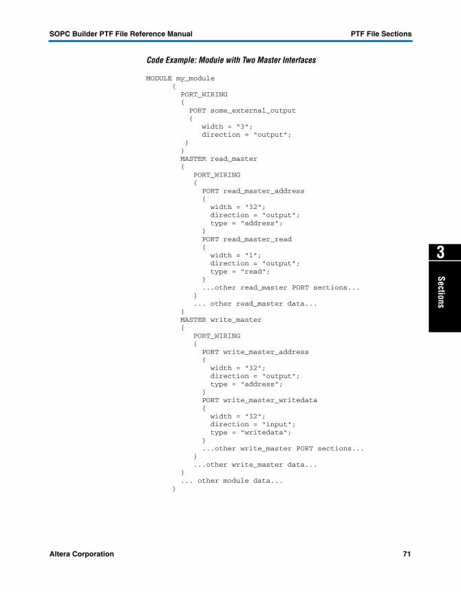
SOPC Builder PTF File Reference Manual PTF File Sections
Sections
3
Code Example: Module with Two Master Interfaces
MODULE my_module { PORT_WIRING { PORT some_external_output { width = “3”; direction = “output”; } } MASTER read_master { PORT_WIRING { PORT read_master_address { width = "32"; direction = "output"; type = "address"; } PORT read_master_read { width = "1"; direction = "output"; type = "read"; } ...other read_master PORT sections... } ... other read_master data... } MASTER write_master { PORT_WIRING { PORT write_master_address { width = "32"; direction = "output"; type = "address"; } PORT write_master_writedata { width = "32"; direction = "input"; type = "writedata"; } ...other write_master PORT sections... } ...other write_master data... } ... other module data... }
Altera Corporation 71
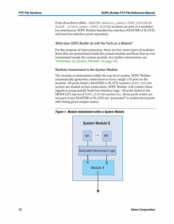
PTF File Sections SOPC Builder PTF File Reference Manual
Ports described within ...MASTER <master_name>/PORT_WIRING or SLAVE <slave_name>/PORT_WIRING sections are part of a modules’ bus interface(s). SOPC Builder handles bus interface (MASTER or SLAVE) and non-bus-interface ports separately.
What does SOPC Builder do with the Ports on a Module?
For the purpose of interconnection, there are two main types of modules: those that are instantiated inside the system module and those that are not instantiated inside the system module. For further information, see "Instantiate_In_System_Module" on page 143.
Modules Instantiated in the System Module
The module is instantiated within the top-level system. SOPC Builder automatically generates connections to every single I/O port on the module. All ports listed a MASTER or SLAVE section’s PORT_WIRING section are treated as bus connections. SOPC Builder will connect these signals to purposefully built bus-interface logic. All ports listed in the MODULE’s top-level PORT_WIRING section (i.e., those ports which are not part of any MASTER or SLAVE) are "promoted" to system-level ports after being given unique names.
Figure 1. Module Instantiated within a System Module
System Module S
Generated Interconnect Logic
A BModule X
C
M1 Mn
72 Altera Corporation

SOPC Builder PTF File Reference Manual PTF File Sections
Sections
3
Consider the example shown in Figure 1. A module X is instantiated within a system module S which contains other modules (M1 through Mn) and interconnect logic generated by SOPC Builder.
The module X has (in this example) two SLAVE interfaces named A and B. The module X also has additional ports (group C) which are not part of either slave interface. The module X would have a MODULE section like this:
MODULE X { PORT_WIRING { PORT first_port_in_group_C { ... contents ... } ... more PORTs in group C } SLAVE A { PORT first_port_for_master_A { ... contents ... } ... more PORTs for slave A } SLAVE B { PORT first_port_for_master_B { ... contents ... } ... more PORTs for slave B } }All of the ports in group C appear as top-level ports of the system (after being reassigned unique names).
Modules NOT Instantiated in the System Module
Consider the example shown in Figure 2. A module X is used by a system but is NOT instantiated inside the system module. The system module includes other modules (M1 through Mn) and interconnect logic generated by SOPC Builder. The module X in this example has two SLAVE interfaces named A and B.
Altera Corporation 73

PTF File Sections SOPC Builder PTF File Reference Manual
Figure 2. Module NOT Instantiated in the System Module
The module X also has additional ports (group C) that are not part of either slave interface. In this case, system module S which is generated by SOPC Builder, will be constructed with I/O ports specifically created for connecting to SLAVE interfaces A and B. The individual I/O ports on S will be named based on their destinations in the A and B interfaces. In this case, SOPC Builder will ignore all ports in group C.
As with all modules NOT instantiated in the system module, it is up to the user to perform manually all interconnections between the external modules’ IO ports and the SOPC Builder system module. We strongly recommend that users (and IP developers) instantiate modules within the system module whenever possible. This reduces error and confusion, and tends to significantly speed the system design process (the point of SOPC Builder in the first place). Designers should use the external-connection facility only for interfacing to off-chip devices (e.g., SRAM chips) or only when instantiating a block inside the system module is, for some reason, impossible.
A BModule X
C
System Module S
Generated Interconnect Logic
M1 Mn
?
74 Altera Corporation

SOPC Builder PTF File Reference Manual PTF File Sections
Sections
3
Special Rules for Port-Type
For a description of the kinds of port types that can appear in a module see "type" on page 210.
Handling clk and reset Signals
As described above, there are two types of PORT_WIRING sections: those within a MASTER or SLAVE section, and those at the top level of a MODULE (not in any MASTER or SLAVE section). PORTs which are contained in a top level port-wiring section are, in general, promoted to system-level I/Os. This is not the case if the PORT has a type-assignment of clk, reset, or reset_n. In any of these three cases, the PORT is automatically connected to the system clk or reset (as appropriate) and NOT promoted to a system-level port.
PORTs or type clk, reset, and/or resting may also appear in the PORT_WIRING sections contained in MASTER or SLAVE sections. In all cases, these PORTs will be connected to the system clk or reset signals.
Handling Export Type Signals
In general, PORTs which appear within a MODULE’s top-level PORT_WIRING section (i.e., NOT within a MASTER or SLAVE section) do not have a type-assignment.
PORTS which do appear in a PORT_WIRING section contained in a MASTER or SLAVE section can be assigned the special type export. Ports with type export are treated as if they were in the top-level PORT_WIRING section. They are promoted to system-level ports and renamed according to "SYSTEM <system_name>/MODULE <module_name>/PORT_WIRING" on page 70. They are not connected to any internal logic, and they do not "participate" in any way in the MASTER or SLAVE interface that contains them.
PORT_WIRING sections & SOPC Builder Phase Order
PORT_WIRING sections are first used by SOPC Builder during the Bus Generation phase (see "The Bus Generation Phase" on page 33), which comes very near the end of the process. Thus, a module can populate its various PORT_WIRING sections during any previous phase--right up to, and including, its Generator Program phase. It is sometimes useful to populate PORT_WIRING sections from a Generator Program because the exact port-list for a module may have complex dependencies on a module’s parameters, or even on overall system information. For example, the Nios CPU needs to know how many other modules are connected to its data MASTER interface and where they are mapped in memory before it can "know" how wide to make its address-bus.
Altera Corporation 75
PTF File Sections SOPC Builder PTF File Reference Manual
By allowing PORT_WIRING information to be populated at the very last minute, when much system-level information is final, SOPC Builder affords the component author a great deal of flexibility to create complex, context-dependent port-generation programs. Alternatively, for simple components, an author can specify its ports at the earliest time by adding PORT_WIRING sections to the MODULE_DEFAULTS section in the component’s class.ptf file.
SYSTEM <system_name>/MODULE <module_name>/PORT_WIRING/PORT <port_name>
PORT sections appear within three kinds of PORT_WIRING sections:
1. SYSTEM <system_name>/MODULE <module_name>/MASTER <master_name>/PORT_WIRING
2. SYSTEM <system_name>/MODULE <module_name>/SLAVE <slave_name>/PORT_WIRING
3. SYSTEM <system_name>/MODULE <module_name>/PORT_WIRING
The roles and meanings of these three different types of PORT_WIRING sections appear under SYSTEM <system_name>/MODULE <module_name>/PORT_WIRING.
In all cases, PORT_WIRING sections are used to list and describe all the formal interface ports (I/O signals) for a module. PORT_WIRING sections contain PORT sections. Each PORT section describes a single formal port on a module. Within a MODULE section, there must be one and only one PORT section for each interface signal on the module. These PORT sections can appear in any of the PORT_WIRING sections, according to the rules described in the aforementioned section.
A given PORT section specifies the name, width, and direction for a module interface signal. The name of the PORT section is the same as the formal name of the signal. The width and direction are specified by width and direction assignments within the PORT section.
A PORT section may also include a type assignment. Depending on the value of a PORT <port_name>/type assignment, SOPC Builder will generate purpose-built interconnections and logic to implement a specified protocol. See “type” on page 210 for more detailed information about the type assignment.
f See the Avalon Bus Specification Reference Manual at http://www.altera.com/literature/lit-nio.html for a complete description of how different type assignments are handled.
76 Altera Corporation
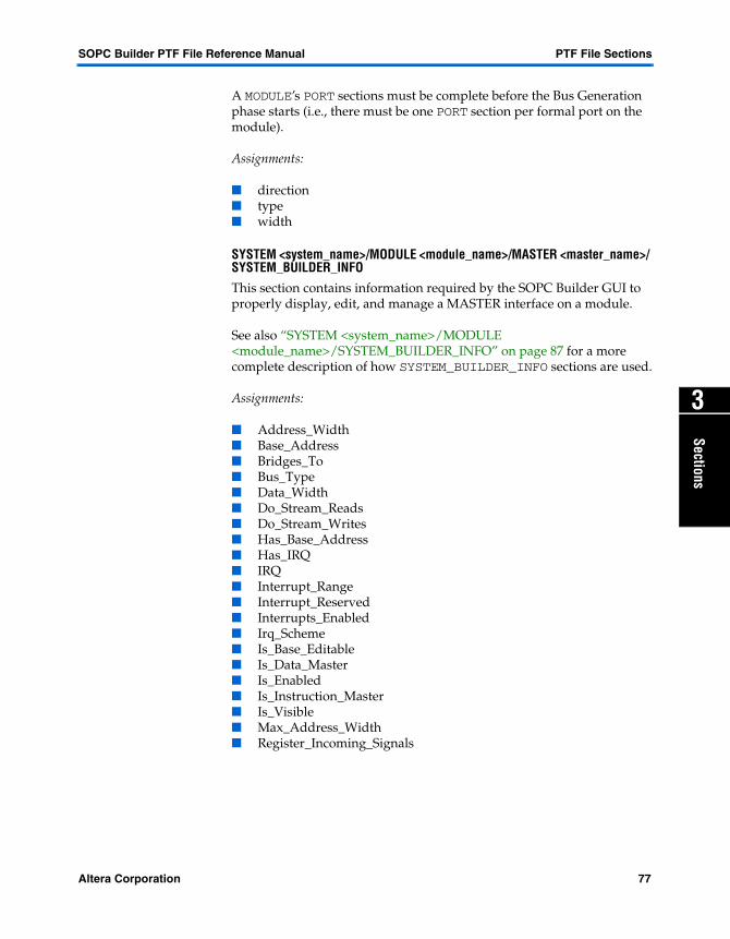
SOPC Builder PTF File Reference Manual PTF File Sections
Sections
3
A MODULE’s PORT sections must be complete before the Bus Generation phase starts (i.e., there must be one PORT section per formal port on the module).
Assignments:
� direction� type� width
SYSTEM <system_name>/MODULE <module_name>/MASTER <master_name>/ SYSTEM_BUILDER_INFO
This section contains information required by the SOPC Builder GUI to properly display, edit, and manage a MASTER interface on a module.
See also “SYSTEM <system_name>/MODULE <module_name>/SYSTEM_BUILDER_INFO” on page 87 for a more complete description of how SYSTEM_BUILDER_INFO sections are used.
Assignments:
� Address_Width� Base_Address� Bridges_To� Bus_Type� Data_Width� Do_Stream_Reads� Do_Stream_Writes� Has_Base_Address� Has_IRQ� IRQ� Interrupt_Range� Interrupt_Reserved� Interrupts_Enabled� Irq_Scheme� Is_Base_Editable� Is_Data_Master� Is_Enabled� Is_Instruction_Master� Is_Visible� Max_Address_Width� Register_Incoming_Signals
Altera Corporation 77

PTF File Sections SOPC Builder PTF File Reference Manual
SYSTEM <system_name>/MODULE <module_name>/MASTER <master_name>/ SYSTEM_BUILDER_INFO/IRQ_MAP
This section describes the interconnection between the slave’s IRQs and the master IRQ bus. It is applicable only for masters that may accept multiple IRQs (port of type irq with width > 1). This section is currently ONLY used for AHB bus generation, and will only be used if the master’s Bus_Type is AHB.
SOPC Builder is instructed on which slaves’ irqs connect to which master irq bits by the IRQ_MAP section. If the IRQ_MAP section exists, then SOPC Builder will wire up the interrupts according to the IRQ_MAP’s assignments in the System Bus Generation phase.
AHB IRQs have several defined behaviors. The simplest of these, and the only one currently supported by SOPC Builder, is the individual_requests behavior, whereby each bit of the master’s irq bus is individually assigned to one and only one slave irq. Slave irqs may be assigned to more than one bit of the master’s irq. The format for the assignment is:
irq<bit number> = "<MODULE name>/<SLAVE name>"
where
<bit number> = which bit of the master irq bus is being assigned (0 is LSB).
<MODULE name> = name of MODULE section of the PTF file that contains the target irq slave. <SLAVE name> = name of targeted SLAVE section of the PTF file, which contains a valid irq port, to be connected to this bit of the master irq bus. See the following example:
78 Altera Corporation
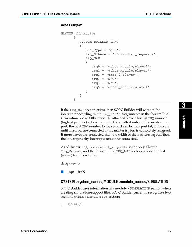
SOPC Builder PTF File Reference Manual PTF File Sections
Sections
3
Code Example:
MASTER ahb_master { SYSTEM_BUILDER_INFO { Bus_Type = "AHB"; Irq_Scheme = "individual_requests"; IRQ_MAP { irq0 = "other_module/slave0"; irq1 = "other_module/slave1"; irq2 = "uart_0/slave0"; irq3 = "N/C"; irq4 = "N/C"; irq5 = "other_module/slave0"; } } }
If the IRQ_MAP section exists, then SOPC Builder will wire up the interrupts according to the IRQ_MAP’s assignments in the System Bus Generation phase. Otherwise, the attached slave’s lowest IRQ number (highest priority) gets wired up to the smallest index of the master irq port, the next IRQ number to the second master irq port bit, and so on, until all slaves are connected or the master irq bus is completely assigned. If more slaves are connected than the width of the master's irq bus, then the lowest priority interrupts remain unconnected.
As of this writing, individual_requests is the only allowed Irq_Scheme, and the format of the IRQ_MAP section is only defined (above) for this scheme.
Assignments:
� irq0 ... irqN
SYSTEM <system_name>/MODULE <module_name>/SIMULATION
SOPC Builder uses information in a module's SIMULATION section when creating simulation-support files. SOPC Builder currently recognizes two sections within a SIMULATION section:
1. DISPLAY
Altera Corporation 79

PTF File Sections SOPC Builder PTF File Reference Manual
The DISPLAY section contains a list of signals that the component author deemed "interesting," and which will be automatically added to the generated "interesting waveform" configuration file (accessed via the w macro).
2. ModelSim®
The ModelSim section contains commands and setup information specifically targeted for ModelSim support of the enclosing module. If future versions of SOPC Builder support project file creation for simulators other than ModelSim, there will probably be additional sections in the above list for the other simulation tools. Each of these subsections is described in more detail in its own documentation entry.
Information in the SIMULATION section is used during the Project File Generation phase. Often, SIMULATION information is specified early (e.g., in the class.ptf’s MODULE_DEFAULTS section) and not changed. Some modules, especially those whose set of "interesting" waveforms is highly parameterized, may populate the SIMULATION section during their Generator Program phase.
Assignment:
� Fix_Me_Up
SYSTEM <system_name>/MODULE <module_name>/ SIMULATION/ DISPLAYDuring the Project File Generation phase, SOPC Builder automatically creates a ModelSim project directory for simulating the constructed system. One of the several simulator-configuration files created is a waveform-window setup file. This file gives the user quick access (e.g.,via the w macro) to a waveform display window populated with "interesting" signals from the system.
The generated waveform-configuration file is named wave_presets.do. It appears in the generated simulation-directory <system_name>_sim/. This file can be read, modified, and copied by ModelSim just like any other waveform-configuration file. SOPC Builder also defines a convenient macro (w) for quickly loading this particular waveform configuration.
The list of "interesting" signals is the union of all signals from all MODULE sections’ SIMULATION/DISPLAY sections. Signals listed in the DISPLAY section of any module will appear in the generated ModelSim waveform window.
80 Altera Corporation

SOPC Builder PTF File Reference Manual PTF File Sections
Sections
3
The DISPLAY section contains SIGNAL section – one per signal displayed in the simulator's waveform window. Each SIGNAL section names a signal to be displayed and contains information about how that signal should be formatted.
SOPC Builder automatically inserts a divider in the waveform window above the signals associated with each module. For example, between each group of signals from distinct ...MODULE <module_name>/SIMULATION/DISPLAY sections. The name displayed in the inter-module divider is the same as the name of the MODULE section.
The signals in any DISPLAY section appear in the waveform window in a well-defined order. Each SIGNAL section has a section name which is not the name of the signal. The name of the signal is given as an assignment inside the SIGNAL section. The waveforms are displayed in order according to their SIGNAL section names, alphabetically.
This gives the component author control over the order in which a module's signals appear in the waveform window, independent of the names of the signals displayed.
MODULE my_module { ...other MODULE data... SIMULATION { DISPLAY { SIGNAL aaaardvark { name = "write_enable"; } ... other SIGNAL sections... SIGNAL zzzzanzibar { name = "data_out"; } ...other SIMULATION data... } } }
In the above example, the write_enable signal will be displayed in the waveform window above the data_out signal because the SIGNAL sections will be ordered alphabetically by section name. The SIGNAL section names are used only for ordering, and are otherwise ignored.
Altera Corporation 81

PTF File Sections SOPC Builder PTF File Reference Manual
The contents of the DISPLAY section is used during the Project File Generation phase. Also see “SYSTEM <system_name>/MODULE <module_name>/SIMULATION” on page 79.
SYSTEM <system_name>/MODULE <module_name>/ SIMULATION/DISPLAY/ SIGNAL <alphabetical index>
During the Project File Generation phase, SOPC Builder creates simulator-setup files, including a waveform configuration file that gives the user quick access to a waveform window pre-populated with “interesting” signals. See “SYSTEM <system_name>/MODULE <module_name>/ SIMULATION/ DISPLAY” on page 80 for more background information.
Each signal displayed in the automatically-generated waveform window has an associated SIGNAL section. The name of the SIGNAL section is not the same as the formal HDL-signal name. The name of the SIGNAL section is used only for display-ordering. The waveforms are displayed alphabetically in order by their SIGNAL section names. The SIGNAL section names are otherwise ignored. The actual HDL signal names are given by the name assignment inside the SIGNAL section.
Contents of SIGNAL sections are used during the Project File Generation phase.
Assignments:
� conditional� format� name� radix
SYSTEM <system_name>/MODULE <module_name>/SIMULATION/MODELSIM
At present, SOPC Builder creates simulation project files only for the ModelSim simulator. Future versions of SOPC Builder may support other simulation tools. As described elsewhere (see “SYSTEM <system_name>/MODULE <module_name>/ SIMULATION/ DISPLAY” on page 80.), each MODULE's SIMULATION section can provide simulator-setup data specific to that module. Generic tool-information data (e.g., a list of waveforms to display) may be used by any tool in the future.
Some simulation information, like tool-setup commands, is simulator specific. Any simulator-specific information should appear in a sub-section of SIMULATION dedicated to that particular simulator.
82 Altera Corporation

SOPC Builder PTF File Reference Manual PTF File Sections
Sections
3
The only tool-specific SIMULATION sub-section currently supported is the MODELSIM section. This section contains setup commands and other data which is specific to the ModelSim simulator.
Data in the MODELSIM section is used during the Project File Generation phase.
SYSTEM <system_name>/MODULE <module_name>/SIMULATION/MODELSIM/ SETUP_COMMANDS
SOPC Builder creates a ModelSim simulation project when it generates a system. The simulation project contains various tool setup files. One of the generated files is called virtuals.do. The generated simulation project automatically runs all the commands in the virtuals.do file whenever the design-data is reloaded.
Specifically, the ModelSim command do virtuals.do is part of the automatically-defined s macro. Whenever the user invokes the s macro, all commands in virtuals.do are executed.
In general, virtuals.do contains setup commands. A component author can add commands to this file by adding assignments to the...MODELSIM/SETUP_COMMANDS section.
Any assignment values in the SETUP_COMMANDS section are copied into the virtuals.do file. Commands are copied from the SETUP_COMMAND section into the virtuals.do file in an arbitrary order. This process is slightly counterintuitive because only the assignment-values are used...the assignment names are ignored (except that all assignment names in the SETUP_COMMANDS section must be unique).Consider the following example:
Code Example: SETUP_COMMAND
MODULE my_module { ...other module data... SIMULATION { MODELSIM { SETUP_COMMANDS { ignored_assignment_name_1 = "<first-setup-command>"; ignored_assignment_name_2 = "<second-setup-command>"; ignored_assignment_name_1 = "<third-setup-command>"; } } } }
Altera Corporation 83

PTF File Sections SOPC Builder PTF File Reference Manual
In this example, the following text would be written into the virtuals.do file:
<first-setup-command> <second-setup-command> <third-setup-command>
Where <first-setup-command>, etc. are well-formed ModelSim tool commands suitable for inclusion in a .do-script. The assignment values are separated by new lines. The assignment names are discarded.
f See ModelSim product documentation for a complete list of available script commands.
Path Substitution
Many ModelSim script commands (e.g., virtual function definitions) require the full hierarchical name of a signal. The component author has no way of knowing the full path to the module when the component is created. The full hierarchical path to a signal will (of course) contain the name of both the system module and the user-provided name of the containing module. The following string:
__MODULE_PATH__
(two leading underscores and two trailing underscores) Is recognized anywhere it appears within an assignment-value string inside the SETUP_COMMANDS section. SOPC Builder automatically substitutes this string in its place:
/test_bench/DUT/the_<module_name>
Where <module-name> is the name of the enclosing MODULE section. (This substitution shows that the test-bench module is named test_bench, and it has an instance of the system module named DUT, which has an instance of the enclosing module named the_<module_name>. Data in the SETUP_COMMANDS section are used during the Project File Generation phase.
Assignments:
� Assignment-names are discarded.� Assignment-names must be unique within the section.� All assignment -values- are used.
84 Altera Corporation

SOPC Builder PTF File Reference Manual PTF File Sections
Sections
3
SYSTEM <system_name>/MODULE <module_name>/SIMULATION/MODELSIM/ TYPES
1 Please see “SYSTEM <system_name>/MODULE <module_name>/SIMULATION/MODELSIM/ SETUP_COMMANDS” on page 83 first.
Mechanically, assignments in the TYPES section are handled exactly like assignments in the SETUP_COMMANDS section, with one exception: No __MODULE_PATH__ path-substitution is performed.
All assignment-names in the TYPES section are ignored. All assignment value strings are copied, one value per line, into the generated virtuals.do file in the <system-name>_sim/ simulation directory.
Conventionally, the TYPES section is used to define virtual signal types (see ModelSim documentation) although a component author can, technically, add any assignment-value destined for the virtuals.do file. Data in the TYPES section are used during the Project File Generation phase.
Assignments:
� Assignment-names are discarded.� Assignment-names must be unique within the section.� All assignment -values- are used.
SYSTEM <system_name>/MODULE <module_name>/SLAVE <slave_name>/ SYSTEM_BUILDER_INFO
This section contains information required by the SOPC Builder GUI to properly display, edit, and manage a SLAVE interface on a module.
See also “SYSTEM <system_name>/MODULE <module_name>/SYSTEM_BUILDER_INFO” on page 87for a more complete description of how SYSTEM_BUILDER_INFO sections are generally used.
Assignments:
� Active_CS_Through_Read_Latency� Address_Alignment� Address_Span� Address_Width� Base_Address� Bridges_To� Bus_Type� Connection_Limit� Data_Width
Altera Corporation 85

PTF File Sections SOPC Builder PTF File Reference Manual
� Has_Base_Address� Has_IRQ� Hold_Time� IRQ� IRQ_Number� Instantiate_In_System_Module� Is_Base_Editable� Is_Base_Locked� Is_Custom_Instruction� Is_Enabled� Is_Memory_Device� Is_Printable_Device� Is_Visible� Master_Arbitration� Minimum_Span� Read_Latency� Read_Wait_States� Register_Incoming_Signals� Register_Outgoing_Signals� SDK_Use_Slave_Name� Setup_Time� Write_Wait_States
SYSTEM <system_name>/MODULE <module_name>/SLAVE <slave_name>/ SYSTEM_BUILDER_INFO/MASTERED_BY <master_name>
This section contains descriptions about how the slave is mastered. The master_name specifies which master the slave is mastered by and is specified by MODULE_NAME/Master_Name. This section should not be set in the class.ptf/MODULE_DEFAULTS section since the class.ptf is unaware of the masters in any given system. See the example below:
SYSTEM my_system { MODULE my_first_module { MASTER some_master { } } MODULE my_second_module { SLAVE some_slave { SYSTEM_BUILDER_INFO { MASTERED_BY my_first_module/some_master {
86 Altera Corporation

SOPC Builder PTF File Reference Manual PTF File Sections
Sections
3
} MASTERED_BY my_third_module/some_master { } } } } MODULE my_third_module { MASTER some_master { } } }
Assignment:
� priority
SYSTEM <system_name>/MODULE <module_name>/SYSTEM_BUILDER_INFO
The SOPC Builder GUI must have a certain amount of limited information about a module in order to display it properly in the address-map table. SOPC_Builder also requires additional limited information about a module to generate it properly, create SDK-support for it, etc. SYSTEM_BUILDER_INFO sections provide this information.
SOPC Builder recognizes more than one SYSTEM_BUILDER_INFO section per MODULE section. It recognizes one SYSTEM_BUILDER_INFO section immediately contained within the MODULE section, and then one additional SYSTEM_BUILDER_INFO section within each of the module’s MASTER or SLAVE sections. The SYSTEM_BUILDER_INFO sections inside a MASTER or SLAVE section contain enough information to display properly that MASTER or SLAVE in the GUI (address-map table, etc.). The MODULE’s top-level SYSTEM_BUILDER_INFO section contains assignments which apply to the entire module (e.g., the Is_Enabled setting, which applies to the entire module and all its interfaces).
As a general rule, SYSTEM_BUILDER_INFO sections contain data that control how the module is displayed and handled by SOPC Builder, but which is NOT:
� Specific port information (contained in PORT_WIRING sections)
� Module configuration parameters (conventionally contained in WIZARD_SCRIPT_ARGUMENTS sections, per the choice of the component author)
Altera Corporation 87

PTF File Sections SOPC Builder PTF File Reference Manual
In some cases, the partitioning of assignments among the various sections within a MODULE is somewhat arbitrary. See “SYSTEM <system_name>/MODULE <module_name>/MASTER <master_name>/ SYSTEM_BUILDER_INFO” on page 77 and “SYSTEM <system_name>/MODULE <module_name>/SLAVE <slave_name>/ SYSTEM_BUILDER_INFO” on page 85.
Assignments:
� Date_Modified� Fixed_Module_Name� Instantiate_In_System_Module� Is_Altera_Supplied� Is_Bridge� Is_CPU� Is_Custom_Instruction� Is_Enabled� Is_Memory_Device� Is_Visible� Make_Memory_Model� Module_Desc� Name_Is_Read_Only� Prohibited_Device_Family� Required_Device_Family
SYSTEM <system_name>/MODULE <module_name>/SYSTEM_BUILDER_INFO/ View
This section contains descriptions of how to display this module in the module table. The assignments in this section are made either by the SOPC Builder GUI directly, or by the Add/Edit programs as a means of passing descriptive information about the module for display by the SOPC Builder GUI. This section is created and maintained by the SOPC Builder GUI and does not need to exist in the MODULE_DEFAULTS section of the class.ptf, although it is certainly not illegal to include it there. In the case of a component that does not have an Add/Edit program, it could be useful to default the Settings_Summary to the string you would like to see for the tool tip for this module.
Assignments:
� Is_Collapsed� Settings_Summary
88 Altera Corporation

SOPC Builder PTF File Reference Manual PTF File Sections
Sections
3
SYSTEM <system_name>/MODULE <module_name>/SYSTEM_BUILDER_INFO/View/MESSAGES
This section contains messages pertaining to this module that SOPC Builder GUI will display in its message window. Any messages found in this section will be displayed and continue to be displayed until they are removed. This section exists to allow Add/Edit programs to pass messages to the SOPC Builder GUI about the module. This is usually made necessary because of post-processing activity done by an Add/Edit program that does not allow messages to display while it is still running (e.g., the Excalibur Device Wizard). The format of the messages is standard PTF file format. The assignment name (left side) should start with error, warning or any other string. Assignment names that begin with error are indicated in the display as errors, warning as warnings and anything else as informational messages. The assignment value (right side) is the actual message.
Examples:
error= "There was an error in the Add Program. Please fix it.";
warning0= "There was an inconsistent setting in the Add Program. You may want to verify it.";
message= "Have a nice day."
SYSTEM <system_name>/WIZARD_SCRIPT_ARGUMENTS
SOPC Builder only recognizes two kinds of sections within the top-level SYSTEM section of a system PTF file:
1. Any number of MODULE sections
2. One (1) WIZARD_SCRIPT_ARGUMENTS section which is outside of (not contained in) any MODULE section
This top-level SYSTEM <system_name>/WIZARD_SCRIPT_ARGUMENTS section contains global assignments which apply to the entire system. Many of these settings (e.g., clock_freq) are directly coupled to SOPC Builder GUI controls, and are set by the user. Other settings (e.g., name_column_width) are automatically set by the GUI and are saved in this section so that the user’s display choices can be retained.
Assignments:
� clock_freq� generate_hdl
Altera Corporation 89

PTF File Sections SOPC Builder PTF File Reference Manual
� generate_sdk� do_build_sim� skip_synth (ignored & obsolete)� device_family� do_optimize� leo_flatten (ignored & obsolete)� leo_area (ignored & obsolete)� view_master_columns� view_master_priorities� hdl_language� name_column_width� desc_column_width� bustype_column_width� base_column_width� end_column_width� do_log_history
90 Altera Corporation

Altera Corporation
PTF Assignments
4
Assignments
This section provides detailed information about each PTF file assignments. The assignments are in alphabetical order and contains the following information:
� Allowed values� If required� Default value� List of sections that uses the assignment� The phase of system design that requires the assignment to
successfully architecture the design� The assignment’s path� A description� A PTF file example
1 Some of the assignments included in this section are currently obsolete and ignored during system generation. They are identified by a Obsolete & Ignored watermark.
91

PTF Assignments SOPC Builder PTF File Reference Manual
Description: Some latency capable devices, such as SSRAM, require their chip_select to remain active during cycles while their data is read out even if no additional data is being requested. If Active_CS_Through_ Read_Latency is set to 1, The Avalon Tristate Bus Generator will assert the slave’s chipselect until all its data has been read. This setting may be set to one only if the slave is of Bus_Type avalon_tristate and if the slave does not have peripheral-controlled wait states.
Active_CS_Through_Read_Latency
Allowed Values: 0
1
Required: N
Default Values: 0
Used by Phase: System Generation
Required by Phase: System Generation
Path:CLASS <class_name>/MODULE <module name>/SLAVE <slave_name>/SYSTEM_BUILDER_INFO
92 Altera Corporation

SOPC Builder PTF File Reference Manual PTF Assignments
4
Assignments
Description: Whenever a new module (instance of a library component) is added to a system, SOPC Builder runs that component’s Add_Program. The sequence of events is as follows:
1. A user performs a GUI action to request that an instance of a library component be added to their system-under-construction. For example, the user may click Add under the module pool, or select the Add Selected Module item from the System menu.
2. SOPC Builder locates the class.ptf file which defines the selected library component.
3. SOPC Builder creates a new MODULE section in the system’s PTF file. SOPC Builder gives the new MODULE section a default name (which the user may later edit). The MODULE section is filled with a literal copy of all assignments and sections present in the class.ptf file’s CLASS/MODULE_DEFAULTS section.
4. SOPC Builder gets the value of the Add_Program assignment in the class.ptf file’s CLASS/ASSOCIATED_FILES section.
5. SOPC Builder launches the named Add_Program, and provides the Add_Program with command line arguments that specify the system name, system PTF file name, and MODULE section name being added (see "PTF File Sections" on page 63).
6. The component-author-specified Add_Program executes. SOPC Builder does not enforce any hard rules about what an Add_Program can and can’t do. But, conventionally, an Add_Program will present a user-interface (e.g., a wizard) which allows the user to choose an initial configuration for the module
Add_Program
Allowed Values: perl script (*.pl)java ( *.class)java (*. jar)"" (empty string)
Required: N
Default Values: "" (empty string)
Used by Phase: Add
Required by Phase: Component Authoring
Path:CLASS <class_name>/ASSOCIATED_FILES
Altera Corporation 93
PTF Assignments SOPC Builder PTF File Reference Manual
they’re about to add. The Add_Program conventionally stores user preference data in the MODULE’s WIZARD_SCRIPT_ARGUMENTS section, and may or may not need to modify other MODULE data (e.g., SYSTEM_BUILDER_INFO contents) to reflect the user’s choices.
7. Eventually, the Add_Program terminates. For a typical wizard-presentation Add_Program, the user ends the program by clicking Finish.
8. SOPC Builder reads the updated MODULE data, and displays the new module in the address-map table accordingly.
The component-author is responsible for providing the executable program named by the Add_Program assignment value. The Add_Program may point to a PTF file section that implements a user-interface, instead of an executable program.
94 Altera Corporation

SOPC Builder PTF File Reference Manual PTF Assignments
4
Assignments
Description: This parameter sets the address alignment of the slave.
The Avalon bus module accommodates master and slave peripherals of varying, unmatched data widths. For example, 32-bit master ports can access 8-bit slave ports, and 16-bit master ports can access 32-bit slave ports. Whenever master-slave pairs of unmatched data widths exist together in a system, the issue of address alignment comes up.
In the case of a wide master accessing a narrow slave port, the question becomes: What happens to the most significant bits (MSBs) when a wide master reads from (or writes to) a narrow slave? The Avalon bus offers two approaches to handling this situation:
1. Native Address Alignment (Address_Alignment = native) With native address alignment, a single transfer on the master port corresponds to exactly one transfer on the slave port. For example, when a 32-bit master reads from a 16-bit slave port, the Avalon bus module returns a 32-bit unit of data, but only the least significant 16- bits contain valid data from the slave port. The MSBs may be zero or undefined.
2. Dynamic Bus Sizing (Address_Alignment = dynamic) With dynamic bus sizing, when a wide master reads from a narrow slave port, the slave side of the Avalon bus module performs several read transfers--as many as required to fill the master data width with narrow slave units of data. For example, when a 32-bit master reads from an 8-bit slave, the Avalon bus module returns a 32-bit word filled with four valid bytes of data from the slave.
f For further details on Address_Alignment, see the Avalon Bus Specification Reference Manual at http://www.altera.com/literature/lit-nio.html.
Address_Alignment
Allowed Values: dynamic
native
Required: Y
Default Values: native
Used by Phase: Avalon/Avalon Tristate Bus Generator
Required by Phase: SDK/HDL Generation
Path:SYSTEM <system_name>/MODULE <module_name>/SLAVE <slave_name>/SYSTEM_BUILDER_INFO
Altera Corporation 95

PTF Assignments SOPC Builder PTF File Reference Manual
Description: This assignment defines the actual span that this slave occupies. It is used specifically to indicate that this slave may occupy less than the complete range indicated by its Address_Width assignment. It is expected to be a value between 2^(Address_Width-1) and 2^Address_Width (where Address_Width accounts for Bus_Type, Address_Alignment and Data_Width). If this slave occupies less than the entire range of Address_Width, other slave(s) may be packed into the unused region.
It is also used internally by the SOPC Builder GUI for bridges for which the GUI calculates the Base_Address and Address_Span. See “Has_Base_Address’ on page 137 for more information on this calculation.
Address_Span
Allowed Values: 0 – 2^32
Required: N
Default Values: 2^Address_Width
Used by Phase: System Configuration
Required by Phase: System Configuration
Path:SYSTEM<system_name>/MODULE <module_name>/SLAVE <slave_name>/SYSTEM_BUILDER_INFO
96 Altera Corporation

SOPC Builder PTF File Reference Manual PTF Assignments
4
Assignments
Description: This describes how many bits of address space are used by this master (or slave). For Avalon peripherals, the value of Address_Width must be equal to or less than the width of the master’s (or slave’s) port of type address (type haddress for AHB). Those addresses bits that are above a master’s (or slave’s) Address_Width are ignored. Address_Width does not include those address bits that are ignored due to bus sizing (see “Address_Alignment’ on page 95).
f For further details on Address_Width, see the Avalon Bus Specification Reference Manual at http://www.altera.com/literature/lit-nio.html.
Address_Width
Allowed Values: 1–32
Required: Y
Default Values: 0
Used by Phase: System ConfigurationSystem Bus Generation
Required by Phase: System Configuration
Path:SYSTEM <system_name>/MODULE <module_name>/MASTER <master_name>/SYSTEM_BUILDER_INFOSYSTEM <system_name>/MODULE <module_name>/SLAVE <slave_name>/SYSTEM_BUILDER_INFO
Altera Corporation 97

PTF Assignments SOPC Builder PTF File Reference Manual
Description: This assignment is the partial path to a file which will be included as part of the assembly language header file that SOPC Builder creates. The path is rooted in the directory containing the class.ptf file.
asm_header_file
Allowed Values: partial path without component directory
Required: N
Default Values: N/A
Used by Phase: SDK Generation
Required by Phase: SDK Generation
Path:CLASS<class_name>/SDK_GENERATION//SDK_FILES
98 Altera Corporation

SOPC Builder PTF File Reference Manual PTF Assignments
4
Assignments
Description: For masters, this assignment defines the lowest address that is visible to this master. If Base_Address for a master is not set, it defaults to 0x0000. Base_Address is used with Max_Address_Width to compute the complete address range that this master can access. Any slaves that are connected to this master must occupy an address range that is accessible to this master. If the address range is not completely inside the range of the master, SOPC Builder will generate a warning that the slave is only accessible in the region that overlaps with the master’s range.
For slaves, this is the base address that this slave occupies. It must be aligned with the slave’s address range, 2^Address_Width, where Address_Width’ accounts for Bus_Type, Alignment and Data_Width. It may not overlap with other slaves connected to the same master, although it may overlap with the unused region above another slave’s Address_Span. See "Address_Span" on page 96 for more information on this topic.
The Auto-Address feature in SOPC Builder GUI uses Address_Width and Address_Span (if present) to determine the best address to assign to each slave. It sorts slaves from biggest to smallest and assigns addresses in that order. It will always assign an address that aligns with Address_Width. It will also attempt to assign addresses that do not overlap with the unused regions of other slaves. However, if this is not possible, it will try to find unused regions above the Address_Span of another slave. This will generate a warning in the SOPC Builder GUI to indicate that there is extra logic involved in decoding addresses in that range, but it is allowed. This is particularly useful in a 16-bit Nios system which is limited to 64K address range.
Base_Address
Allowed Values: --unknown--
and hexadecimal address
Required: N
Default Values: 0x0000
Used by Phase: System ConfigurationSystem Bus Generation
Required by Phase: System Configuration
Path:SYSTEM <system_name>/MODULE <module_name>/MASTER <master_name>/SYSTEM_BUILDER_INFO
SYSTEM <system_name>/MODULE <module_name>/SLAVE <slave_name>/SYSTEM_BUILDER_INFO
Altera Corporation 99
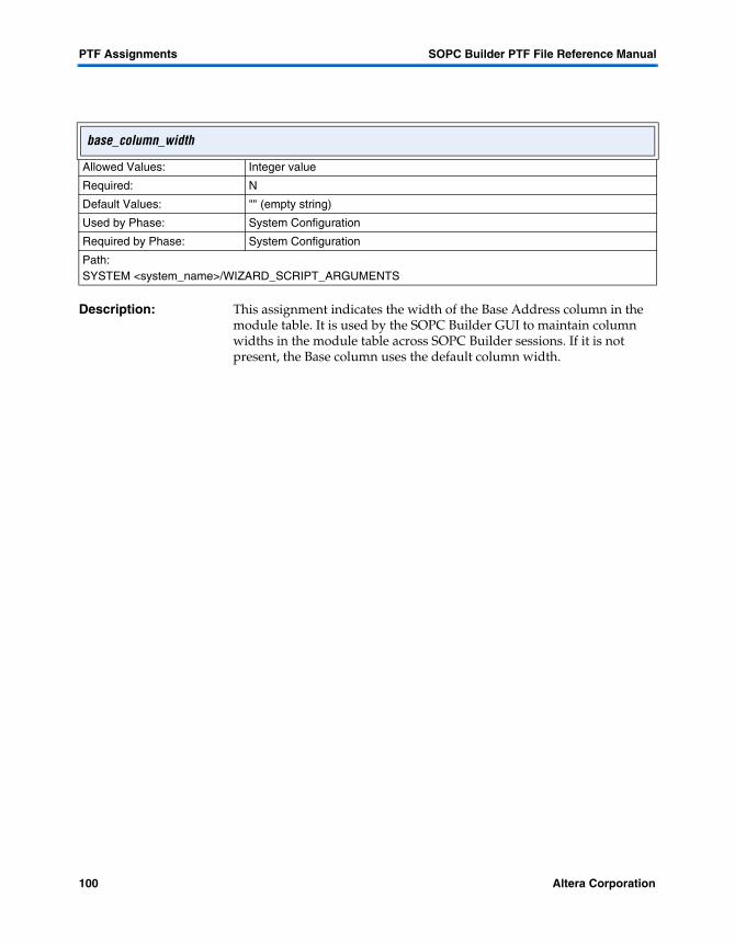
PTF Assignments SOPC Builder PTF File Reference Manual
Description: This assignment indicates the width of the Base Address column in the module table. It is used by the SOPC Builder GUI to maintain column widths in the module table across SOPC Builder sessions. If it is not present, the Base column uses the default column width.
base_column_width
Allowed Values: Integer value
Required: N
Default Values: "" (empty string)
Used by Phase: System Configuration
Required by Phase: System Configuration
Path:SYSTEM <system_name>/WIZARD_SCRIPT_ARGUMENTS
100 Altera Corporation

SOPC Builder PTF File Reference Manual PTF Assignments
4
Assignments
Description: A Bind_Program is used to provide parameterization beyond that of the Add/Edit_Program. Because the binding phase occurs after the system configuration phase, retrospective choices relating to the modules within the entire system can be made. For example, all modules of a particular type could be presented to the user for selection.
A Bind_Program is specified as the name of a WIZARD_UI section within the associated component’s class.ptf file. If no Bind_Program is specified for a module, or no matching WIZARD_UI section is found, no user interface is presented for that module in the binding phase.
The SOPC Builder’s user interface dynamically reflects the various binding-phase programs as modules containing them are added, deleted, and renamed. The label for a given module’s binding user interface is:
More <module-name> Settings
The contents are displayed within a separate tab between the first (system configuration) tab and the last (system generation) tab.
Bind_Program
Allowed Values: the name of WIZARD_UI section
Required: N
Default Values: "" (empty string)
Used by Phase: Bind
Required by Phase: Component Authoring
Path:CLASS <class_name>/ASSOCIATED_FILES
Altera Corporation 101
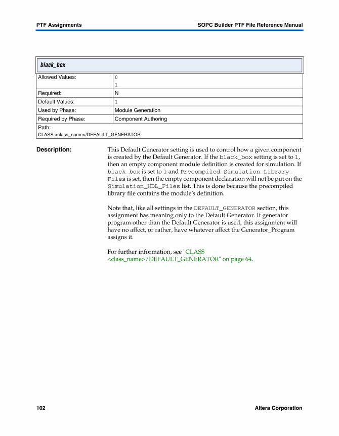
PTF Assignments SOPC Builder PTF File Reference Manual
Description: This Default Generator setting is used to control how a given component is created by the Default Generator. If the black_box setting is set to 1, then an empty component module definition is created for simulation. If black_box is set to 1 and Precompiled_Simulation_Library_ Files is set, then the empty component declaration will not be put on the Simulation_HDL_Files list. This is done because the precompiled library file contains the module’s definition.
Note that, like all settings in the DEFAULT_GENERATOR section, this assignment has meaning only to the Default Generator. If generator program other than the Default Generator is used, this assignment will have no affect, or rather, have whatever affect the Generator_Program assigns it.
For further information, see "CLASS <class_name>/DEFAULT_GENERATOR" on page 64.
black_box
Allowed Values: 0
1
Required: N
Default Values: 1
Used by Phase: Module Generation
Required by Phase: Component Authoring
Path:CLASS <class_name>/DEFAULT_GENERATOR
102 Altera Corporation

SOPC Builder PTF File Reference Manual PTF Assignments
4
Assignments
Description The Default Generator will copy over any file specified on this list from its component directory to the current project directory. This is the setting’s ONLY behavior. If this assignment is not included in the class.ptf file, then no other behavior is assumed.
Note that, by default, the black_box_files assignment includes every file in the component directory with a suffix of .tdf, .edf, .bdf, .bsf, .vqm, or .mif.
Files listed in black_box_files are not included for synthesis or simulation. For further information, see "CLASS <class_name>/DEFAULT_GENERATOR" on page 64.
black_box_files
Allowed Values: A comma delimited string of files (relative or absolute path)
Required: N
Default Values: *.tdf, *.edf, *.bdf, *.bsf, *.vqm, *.mif
Used by Phase: Module Generation
Required by Phase: Component Authoring
Path:CLASS <class_name>/DEFAULT_GENERATOR
Altera Corporation 103

PTF Assignments SOPC Builder PTF File Reference Manual
Description: A bridge has a slave interface on one side and a master interface on the other side. Bridges_To is put in both SLAVE and MASTER sections so that System Bus Generator can look past the bridge to help optimize logic. If set within a slave and the slave Has_Base_Address setting is 1, the system GUI will automatically assign the base address of the bridged slave to encompass all the slaves seen by the bridged master. If Bridges_To is set to a value, then Is_Bridge must be set to 1 in the parent module/SYSTEM_BUILDER_INFO section. Example below:
SYSTEM my_system { MODULE my_bridge_module { SLAVE bridge_slave { SYSTEM_BUILDER_INFO { Bridges_To = "bridge_master"; Has_Base_Address = 0; } } MASTER bridge_master { SYSTEM_BUILDER_INFO { Bridges_To = "bridge_slave"; } } SYSTEM_BUILDER_INFO { Is_Bridge = "1"; } } }
Bridges_To
Allowed Values: slave in this module
Required: N
Default Values: N/A
Used by Phase: System ConfigurationSystem Bus Generation
Required by Phase: System Configuration
Path:SYSTEM <system_name>/MODULE <module_name>/MASTER <master_name>/SYSTEM_BUILDER_INFOSYSTEM <system_name>/MODULE <module_name>/SLAVE<slave_name>/SYSTEM_BUILDER_INFO
104 Altera Corporation

SOPC Builder PTF File Reference Manual PTF Assignments
4
Assignments
If Has_Base_Address is 0, the avalon bus generator will generate chipselects for all slaves which connect to the bridged master. This should only be done for the avalon->avalon_tristate bridges.
Altera Corporation 105
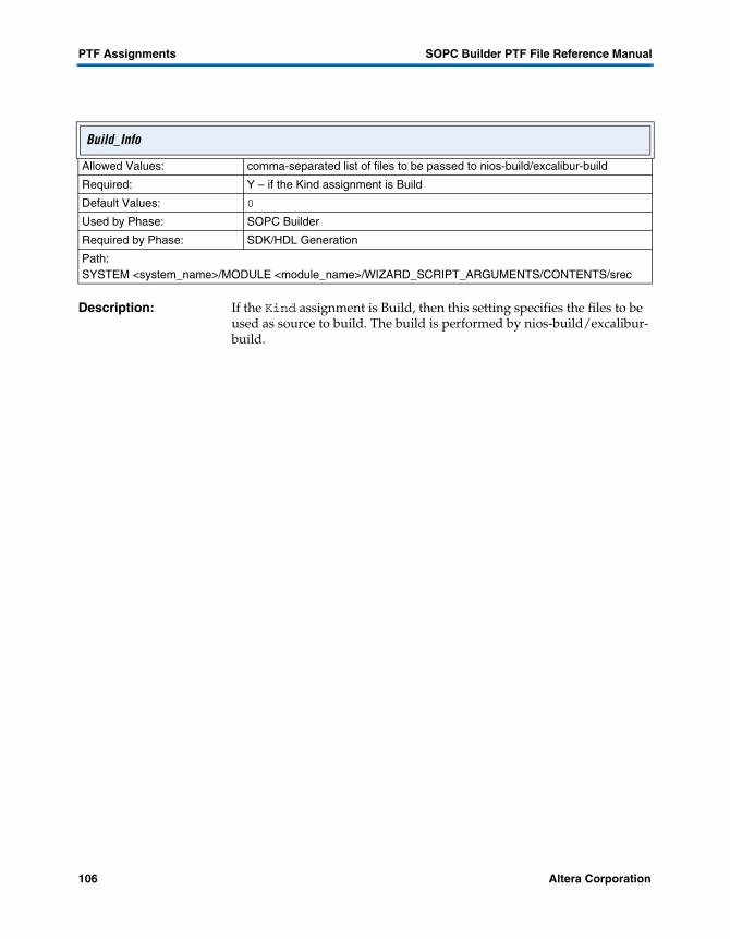
PTF Assignments SOPC Builder PTF File Reference Manual
Description: If the Kind assignment is Build, then this setting specifies the files to be used as source to build. The build is performed by nios-build/excalibur-build.
Build_Info
Allowed Values: comma-separated list of files to be passed to nios-build/excalibur-build
Required: Y – if the Kind assignment is Build
Default Values: 0
Used by Phase: SOPC Builder
Required by Phase: SDK/HDL Generation
Path:SYSTEM <system_name>/MODULE <module_name>/WIZARD_SCRIPT_ARGUMENTS/CONTENTS/srec
106 Altera Corporation

SOPC Builder PTF File Reference Manual PTF Assignments
4
Assignments
Description: Each master or slave is a module’s connection to a certain definition of a bus, and must conform to one bus-type standard. The Bus_Type assignment tells the SOPC Builder which set of bus rules this master/slave must adhere to.
The valid choices are:
� avalon — this master (or slave) connects to an Avalon Bus, and adheres to the Avalon bus specification.
� AHB — this master (or slave) adheres to the AHB AMBA specification.
� avalon_tristate — this master (or slave) is an Avalon tri-state bridge.
� nios_custom_instruction — This master (or slave) constitutes a specialized bus interface that is used by the Nios custom instructions.
Masters may only connect to slaves with the same Bus_Type, and, appropriately, slaves may only be MASTERED_BY masters of the same Bus_Type. In order to connect to slaves of other bus types, a bridge must be inserted in the system. Note that it is not full and sufficient to add a Nios custom instruction by defining a nios_custom_instruction interface.
f See AN188: Custom Instructions for the Nios Embedded Processor and the Avalon Bus Specification Reference Manual at http://www.altera.com/literature/lit-nio.html for further details.
Bus_Type
Allowed Values: AHBavalonavalon_tristatenios_custom_instruction
Required: Y
Default Values: N/A
Used by Phase: System ConfigurationSystem Bus Generation
Required by Phase: System Configuration
Path:SYSTEM <system_name>/MODULE <module_name>/MASTER<master_name>/SYSTEM_BUILDER_INFOSYSTEM <system_name>/MODULE <module_name>/SLAVE <slave_name>/SYSTEM_BUILDER_INFO
Altera Corporation 107

PTF Assignments SOPC Builder PTF File Reference Manual
Description: This assignment indicates the width of the Bus Type column in the module table. It is used by the SOPC Builder GUI to maintain column widths in the module table across SOPC Builder sessions. If it is not present, the Bus Type column uses the default column width.
bustype_column_width
Allowed Values: Integer value
Required: N
Default Values: "" (empty string)
Used by Phase: System Configuration
Required by Phase: System Configuration
Path:SYSTEM <system_name>/WIZARD_SCRIPT_ARGUMENTS
108 Altera Corporation

SOPC Builder PTF File Reference Manual PTF Assignments
4
Assignments
Description: This assignment is the partial path to a file which will be included as part of the C header file that SOPC Builder creates. The path is rooted in the directory containing the class.ptf file.
c_header_file
Allowed Values: partial path within component directory
Required: N
Default Values: N/A
Used by Phase: SDK Generation
Required by Phase: SDK Generation
Path:CLASS<class_name>/SDK_GENERATION//SDK_FILES
Altera Corporation 109
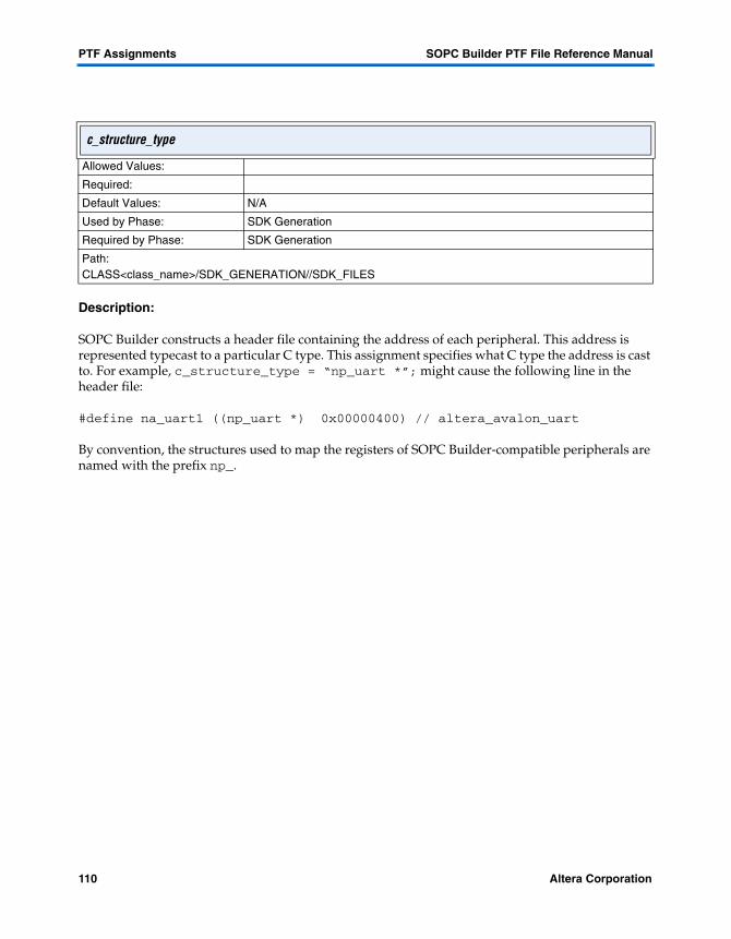
PTF Assignments SOPC Builder PTF File Reference Manual
Description:
SOPC Builder constructs a header file containing the address of each peripheral. This address is represented typecast to a particular C type. This assignment specifies what C type the address is cast to. For example, c_structure_type = “np_uart *”; might cause the following line in the header file:
#define na_uart1 ((np_uart *) 0x00000400) // altera_avalon_uart
By convention, the structures used to map the registers of SOPC Builder-compatible peripherals are named with the prefix np_.
c_structure_type
Allowed Values:
Required:
Default Values: N/A
Used by Phase: SDK Generation
Required by Phase: SDK Generation
Path:CLASS<class_name>/SDK_GENERATION//SDK_FILES
110 Altera Corporation

SOPC Builder PTF File Reference Manual PTF Assignments
4
Assignments
Description: This assignment specifies the class name of this module. It must match <class_name> in the class.ptf section: CLASS <class_name>. It provides a link from the system PTF file back to the source class.ptf file for this module. This link allows the system builder GUI and generator scripts to find relevant information stored only in the class.ptf.
class
Allowed Values: <class_name>
Required: Y
Default Values: 0
Used by Phase: SOPC Builder GUIGenerator Scripts
Required by Phase: Add
Path:SYSTEM <system_name>/MODULE <module_name>
Altera Corporation 111

PTF Assignments SOPC Builder PTF File Reference Manual
Description: This assignment specifies the version of the class.ptf file. It is used by the SOPC Builder GUI to determine whether or not a class.ptf is compatible.
If the value of this assignment is less than the current limit of the SOPC Builder, the GUI will not display the component in the SOPC Builder component pool.
class_version
Allowed Values: Must be greater than or equal to the current version limit of the SOPC Builder GUI (currently 2.0)
Required: Y
Default Values: 0
Used by Phase: SOPC Builder GUIRequired by Phase: Add
Path:SYSTEM <system_name>/MODULE <module_name>
112 Altera Corporation

SOPC Builder PTF File Reference Manual PTF Assignments
4
Assignments
Description: Specifies the frequency of the square wave clock signal which will be fed to the hardware. This influences various aspects of the hardware generation (for example, the divisory value for a fixed baud-rate UART module) and software (for example, the count value in the nr_delay () millisecond delay routine).
clock_freq
Allowed Values: Integer number in Hz
Required: Y
Default Values: N/A
Used by Phase: HDL Generation System Generation
Required by Phase: HDL Generation
Path:SYSTEM <system_name>/WIZARD_SCRIPT_ARGUMENTS
Altera Corporation 113

PTF Assignments SOPC Builder PTF File Reference Manual
Description: If the Kind assignment is Command, then this setting specifies a command to be executed by the Bourne shell (/bin/sh). This may be multiple commands separated by semicolons. Before execution, all occurrences of %1 are replaced by a complete path which is the file SOPC Builder requires the command to generate. Similarly, any %2 is replaced by a complete path to the SDK directory for the CPU which masters this built contents.
Command_Info
Allowed Values: A comma passed to the Bourne shell for execution
Required: Y – if the Kind assignment is Build
Default Values: 0
Used by Phase: SOPC Builder
Required by Phase: SDK/HDL Generation
Path:SYSTEM <system_name>/MODULE <module_name>/WIZARD_SCRIPT_ARGUMENTS/CONTENTS/srec
114 Altera Corporation
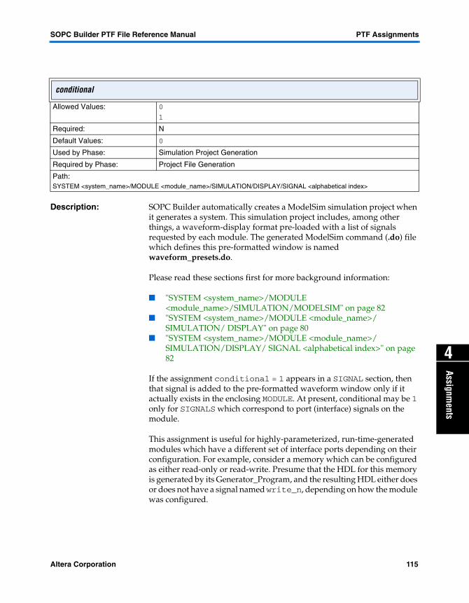
SOPC Builder PTF File Reference Manual PTF Assignments
4
Assignments
Description: SOPC Builder automatically creates a ModelSim simulation project when it generates a system. This simulation project includes, among other things, a waveform-display format pre-loaded with a list of signals requested by each module. The generated ModelSim command (.do) file which defines this pre-formatted window is named waveform_presets.do.
Please read these sections first for more background information:
� "SYSTEM <system_name>/MODULE <module_name>/SIMULATION/MODELSIM" on page 82
� "SYSTEM <system_name>/MODULE <module_name>/ SIMULATION/ DISPLAY" on page 80
� "SYSTEM <system_name>/MODULE <module_name>/ SIMULATION/DISPLAY/ SIGNAL <alphabetical index>" on page 82
If the assignment conditional = 1 appears in a SIGNAL section, then that signal is added to the pre-formatted waveform window only if it actually exists in the enclosing MODULE. At present, conditional may be 1 only for SIGNALS which correspond to port (interface) signals on the module.
This assignment is useful for highly-parameterized, run-time-generated modules which have a different set of interface ports depending on their configuration. For example, consider a memory which can be configured as either read-only or read-write. Presume that the HDL for this memory is generated by its Generator_Program, and the resulting HDL either does or does not have a signal named write_n, depending on how the module was configured.
conditional
Allowed Values: 0
1
Required: N
Default Values: 0
Used by Phase: Simulation Project Generation
Required by Phase: Project File Generation
Path:SYSTEM <system_name>/MODULE <module_name>/SIMULATION/DISPLAY/SIGNAL <alphabetical index>
Altera Corporation 115

PTF Assignments SOPC Builder PTF File Reference Manual
With these PTF file settings:
MODULE my_configurable_memory { ...other module data... SIMULATION { DISPLAY { SIGNAL ignored_section_name { name = "write_n"; conditional = "1"; } } } }
SOPC Builder would add the write_n signal to the pre-formatted waveforms if the write_n signal actually existed, and do nothing if the module was configured so that the write_n signal did not exist.
116 Altera Corporation

SOPC Builder PTF File Reference Manual PTF Assignments
4
Assignments
Description: Sets a limit on the number of masters that can connect to this slave. The default value is 0, which means no limit. The only component that currently uses this assignment is the slave interface on the AHB-Avalon Bridge. It is necessary to restrict the number of masters that can connect to this interface because of the complexity of computing its Base_Address and Address_Span. The complexity stems from the treatment of tri-state bus components. See “Has_Base_Address’ on page 137 for more discussion of this topic.
Connection_Limit
Allowed Values: any integer
Required: N
Default Values: 0 means no limit
Used by Phase: System Configuration
Required by Phase: System COnfiguration
Path:SYSTEM <system system>/MODULE <module_name>/SLAVE <slave_name>/SYSTEM_BUILDER_INFO
Altera Corporation 117

PTF Assignments SOPC Builder PTF File Reference Manual
Description: The cpu_architecture assignment specifies which CPUs an SDK_FILES section applies to. The value of the cpu_architecture assignment matches if it is a substring of the CPU_Architecture assignment (CLASS/MODULE_DEFAULTS/WIZARD_SCRIPT_ARGUMENTS/CPU_Architecture) of a particular CPU. This means that a cpu_architecture value of nios will match both nios_16 and nios_32.
The cpu_architecture assignment has two special values: always and else. The value always matches any CPU_Architecture value. The value else matches any cpu_architecture value, but only if no previous SDK_FILES section matched.
cpu_architecture
Allowed Values: CPU name
Required: N
Default Values: N/A
Used by Phase: SDK Generation
Required by Phase: SDK Generation
Path:CLASS<class_name>/SDK_GENERATION/CPU/QUARTUS_TCL_SCRIPT
118 Altera Corporation

SOPC Builder PTF File Reference Manual PTF Assignments
4
Assignments
Description: This assignment specifies the width of the signals of type writedata and readdata on a master or slave. The Data_Width assignment of a slave is used by the GUI to calculate the amount of system address space a slave will occupy. The Data_Width assignments of a master and slave determine what, if any, interface logic will be generated to handle transactions between the master and slave.
See also: “Address_Alignment’ on page 95
f See the Avalon Bus Specification Reference Manual at http://www.altera.com/literature/lit-nio.html for more native-alignment details.
Data_Width
Allowed Values: Slaves: 8, 16, 32Masters: 16, 32
Required: Y
Default Values: N/A
Used by Phase: System ConfigurationSystem Bus Generation
Required by Phase: System Configuration
Path:SYSTEM <system_name>/MODULE <module_name>/MASTER <master_name>/SYSTEM_BUILDER_INO
SYSTEM <system_name>/MODULE <module_name>/SLAVE <slave_name>/SYSTEM_BUILDER_INFO
Altera Corporation 119

PTF Assignments SOPC Builder PTF File Reference Manual
Description: This assignment indicates the width of the Description column in the module table. It is used by the SOPC Builder GUI to maintain column widths in the module table across SOPC Builder sessions. If it is not present, the Description column uses the default column width.
desc_column_width
Allowed Values: Integer value
Required: N
Default Values: "" (empty string)
Used by Phase: System Configuration
Required by Phase: System Configuration
Path:SYSTEM <system_name>/WIZARD_SCRIPT_ARGUMENTS
120 Altera Corporation

SOPC Builder PTF File Reference Manual PTF Assignments
4
Assignments
Description: This assignment is used by the SOPC Builder GUI for the tool tip to display when the cursor is held over this component’s name in the module pool. If the assignment is not present, the name of the component is re-used for the tool tip.
Code Example:
USER_INTERFACE { USER_LABELS { name="Altera Nios 2.1 CPU"; description="Nios Microprocessor Core with separate Instruction/Data Avalon bus masters"; } }
description
Allowed Values: Text
Required: N
Default Values: "" (empty string)
Used by Phase: System Assembly
Required by Phase: Component Authoring
Path:CLASS <class_name>/USER_INTERFACE/USER_LABELS
Altera Corporation 121

PTF Assignments SOPC Builder PTF File Reference Manual
Description: This assignment is for identifying the target hardware SOPC Builder needs to ensure that proper HDL is generated for the device used.
device_family
Allowed Values: ACEX1KAPEX20K APEX20KCAPEX20KE APEXII|CYCLONEEXCALIBUR_ARM FLEX10K FLEX10KA FLEX10KBFLEX10KEMERCURY STRATIX
Required: Y
Default Values: N/A
Used by Phase: System Generation
Required by Phase: System Generation
Path:SYSTEM <system_name>/WIZARD_SCRIPT_ARGUMENTS
122 Altera Corporation

SOPC Builder PTF File Reference Manual PTF Assignments
4
Assignments
Description: The direction of the module port. The allowed values directly correspond to the direction specified in a verilog port declaration of the module. For vhdl, IN ports should be represented with input. OUT ports should be represented as output. INOUT ports should be represented with inout.
direction
Allowed Values: inoutinputoutput
Required: Y
Default Values: N/A
Used by Phase: System Bus Generation
Required by Phase: System Generation
Path:SYSTEM <system_name>/MODULE <module_name>/MASTER <master_name>/PORT_WIRING/PORT <port_name>
SYSTEM <system_name>/MODULE <module_name>/PORT_WIRING/PORT <port_name>SYSTEM <system_name>/MODULE <module_name>/SLAVE <slave_name>/PORT_WIRING/PORT <port_name>
Altera Corporation 123

PTF Assignments SOPC Builder PTF File Reference Manual
Description: When this assignment is set to 1, the value specifies that master <master_name> supports streaming reads. When the master performs a read access on a slave which supports streaming reads, the system bus will force the master to wait until data is available to be read.
f See the Avalon Bus Specification Reference Manual at http://www.altera.com/literature/lit-nio.html for detailed streaming information.
Do_Stream_Reads
Allowed Values: 0
1
Required: N
Default Values: 0
Used by Phase:
Required by Phase:
Path:SYSTEM <system_name>/MODULE <module_name> /MASTER <master_name>/SYSTEM_BUILDER_INFO
124 Altera Corporation

SOPC Builder PTF File Reference Manual PTF Assignments
4
Assignments
Description: When this assignment is set to 1, the value specifies that master <master_name> supports streaming writes. When the master performs a write access on a slave which supports streaming writes, the system bus will force the master to wait until the slave can accept data.
f See the Avalon Bus Specification Reference Manual at http://www.altera.com/literature/lit-nio.html for detailed streaming information.
Do_Stream_Writes
Allowed Values: 0
1
Required: N
Default Values: 0
Used by Phase:
Required by Phase:
Path:SYSTEM<system_name>/MODULE <module_name> /MASTER <master_name>/SYSTEM_BUILDER_INFO
Altera Corporation 125

PTF Assignments SOPC Builder PTF File Reference Manual
Description: This program runs when the user edits a component in the system. Whenever a module (instance of a library component) is edited system, SOPC Builder runs that component’s Edit_Program. Usually, the Edit_Program is the same as the Add_Program. Shared add/edit programs typically present a GUI for initially configuring a module (when adding), and the same interface before configuring the module later (when editing).
SOPC Builder allows separate Add_Program and Edit_Program assignments to accommodate library components which need to do "something extra" or"something different" when initially added to the system. In practice, most library components have the same Add_Program and Edit_Program.
When a module is edited, the sequence of events is:
1. 1) A user performs a GUI action to begin editing a particular module in the system. For example, the user may double-click on the module’s row in the address table, or may select Edit from the Module menu.
2. 2) SOPC Builder locates the class.ptf file which defines the selected library component.
3. 3) SOPC Builder gets the value of the Edit_Program assignment in the class.ptf file’s CLASS/ASSOCIATED_FILES section.
4. SOPC Builder executes the named Edit_Program, and provides the Edit_Program with command line arguments that specify the system name, system PTF file name, and MODULE-section name being added (see "PTF File Sections" on page 63).
Edit_Program
Allowed Values: perl script (*.pl)java (*.class)java (*.jar)"" (empty string)
Required: N
Default Values: "" (empty string)
Used by Phase: Edit Phase
Required by Phase: Component Authoring
Path:CLASS<class_name>/ASSOCIATED_FILES
126 Altera Corporation
SOPC Builder PTF File Reference Manual PTF Assignments
4
Assignments
5. The component-author-specified Edit_Program runs, and done whatever it does. SOPC Builder does not enforce any hard rules about what an Edit_Program can and cannot do. But, conventionally, an Edit_Program will present a user-interface (e.g., a wizard) which allows the user to reconfigure the selected module. The Edit_Program conventionally stores user preference data in the MODULE’s WIZARD_SCRIPT_ARGUMENTS section, and may or may not need to modify other MODULE data (e.g., SYSTEM_BUILDER_INFO contents) to reflect the user’s choices.
6. Eventually, the Edit_Program terminates (ends). For a typical wizard-presentation Edit_Program, the user ends the program by pressing Finish.
7. SOPC Builder reads the updated MODULE data, and displays the new module in the address-map table accordingly.
The component-author is, of course, responsible for providing the executable program named by the Edit_Program assignment value (see "Edit_Program" on page 126) may point to a PTF section which implements a user-interface, instead of an executable program.
Altera Corporation 127

PTF Assignments SOPC Builder PTF File Reference Manual
Description: This assignment indicates the width of the End Address column in the module table. It is used by the SOPC Builder GUI to maintain column widths in the module table across SOPC Builder sessions. If it is not present, the End column uses the default column width.
end_column_width
Allowed Values: Integer value
Required: N
Default Values: "" (empty string)
Used by Phase: System Configuration
Required by Phase: System Configuration
Path:SYSTEM <system_name>/WIZARD_SCRIPT_ARGUMENTS
128 Altera Corporation
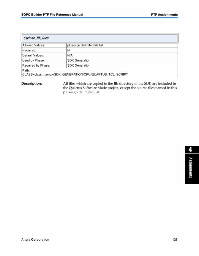
SOPC Builder PTF File Reference Manual PTF Assignments
4
Assignments
Description: All files which are copied to the lib directory of the SDK are included in the Quartus Software Mode project, except the source files named in this plus-sign delimited list.
exclude_lib_files
Allowed Values: plus-sign delimited file list
Required: N
Default Values: N/A
Used by Phase: SDK Generation
Required by Phase: SDK Generation
Path:CLASS<class_name>/SDK_GENERATION/CPU/QUARTUS_TCL_SCRIPT
Altera Corporation 129

PTF Assignments SOPC Builder PTF File Reference Manual
Description: The Fixed_Module_Name setting forces a component to have a specific name when added to the system. The module’s name cannot be changed once it is added. This also has the effect of disallowing multiple instances of a module type to be added to a system.
By default, the absence of this setting implies that the SOPC Builder should generate an initial name for a module when it is added, and also allow the user to rename the module during system edit.
Fixed_Module_Name
Allowed Values: Any text, subject to module-naming rules
Required: N
Default Values: "" (empty string)
Used by Phase: SOPC Builder GUI
Required by Phase: Add
Path:SYSTEM <system_name>/MODULE <module_name>/SYSTEM_BUILDER_INFO
130 Altera Corporation

SOPC Builder PTF File Reference Manual PTF Assignments
4
Assignments
Description: SOPC Builder automatically creates a ModelSim simulation project when it generates a system. This simulation project includes, among other things, a waveform-display format pre-loaded with a list of signals requested by each module. The generated ModelSim command (.do) file which defines this pre-formatted window is named waveform_presets.do
Please read these sections first for more background information:
� "SYSTEM <system_name>/MODULE <module_name>/SIMULATION" on page 79
� "SYSTEM <system_name>/MODULE <module_name>/ SIMULATION/ DISPLAY" on page 80
� "SYSTEM <system_name>/MODULE <module_name>/ SIMULATION/DISPLAY/ SIGNAL <alphabetical index>" on page 82.
There will be one SIGNAL section for each waveform in the pre-formatted window. Waveforms may, optionally, specify a particular display-format using the format assignment within the SIGNAL section.
The format-value Divider is specially recognized by SOPC Builder. All SIGNAL sections with format = Divider will correspond to a divider displayed in the waveform window. The text displayed on the divider will be taken from the SIGNAL’s name assignment value.
format
Allowed Values: DividerLiteralLogic
Required: N
Default Values: See description
Used by Phase: System Bus Generator Program
Required by Phase: SDK/HDL Generation
Path:SYSTEM <system_name>/MODULE <module_name>/SIMULATION/DISPLAY/SIGNAL <alphabetical index>
Altera Corporation 131

PTF Assignments SOPC Builder PTF File Reference Manual
All other values of this assignment is passed directly to ModelSim, so any valid ModelSim format-value is allowed. For example, here is a SIGNAL section below;
MODULE my_module { ...other module data... SIMULATION { DISPLAY { SIGNAL aaa_ardvark_ignored { name = "first_signal_name"; radix = "hexadecimal"; format = "Literal"; } SIGNAL divider_section_name_ignored { name = "and now, for something completely different:"; format = "Divider"; } SIGNAL zzz_zanzibar_ignored { name = "second_signal_name"; format = "Logic"; } } } }
In this example, first_signal_name would display as a hexadecimal, literal value and second_signal_name as a logic (waveform) value, separated by a divider with the indicated text. If no format value is specified, then ModelSim will select the default format for the waveform display.
This value is used during the Project File Generation phase, and can often be set during the Component Authoring phase (because, in general, the list of "interesting" signals, and how they should be displayed, is known when each module is created).
132 Altera Corporation

SOPC Builder PTF File Reference Manual PTF Assignments
4
Assignments
Description: This assignment corresponds directly to the check box on the last panel of the SOPC Builder GUI. If set, then new HDL files (Verilog or VHDL) are created based on the SOPC Builder configuration, and each module’s parameters.
generate_hdl
Allowed Values: 0
1
Required: Y
Default Values: N/A
Used by Phase: SOPC Builder GUI
Required by Phase: HDL/SDK Generation
Path:SYSTEM <system_name>/WIZARD_SCRIPT_ARGUMENTS
Altera Corporation 133

PTF Assignments SOPC Builder PTF File Reference Manual
Description: This assignment corresponds directly to the check box on the last panel of the SOPC Builder GUI. If set, then a new SDK directory and header file set is generated for each CPU master in the system. Also, if set, the memory contents for any module which has a CONTENTS section are regenerated, as an S-Record file.
generate_sdk
Allowed Values: 0
1
Required: Y
Default Values: N/A
Used by Phase: SOPC Builder GUI
Required by Phase: SDK/HDL Generation
Path:SYSTEM <system_name>/WIZARD_SCRIPT_ARGUMENTS
134 Altera Corporation

SOPC Builder PTF File Reference Manual PTF Assignments
4
Assignments
Description: The Generator_Program assignment names a perl script which does one or more of the following tasks:
� Generates HDL, based on parameters in the MODULE <module_name>/WIZARD_SCRIPT_ARGUMENTS section
� Adds MODULE <module_name>/PORT_WIRING sections, as needed- creates SDK components
� Sets MODULE <module_name>/SYSTEM_BUILDER_INFO, as needed- modifies class.ptf settings
Components with a low degree of parametrization have no need of a custom generator program. Common tasks such as copying HDL files from the component directory into the system directory can be handled by the Default Generator Program, described in “Module Default Generator Program’ on page 31. To specify the default generator program, set Generator_Program to either "" or --default--. If no actions need to occur at system generation time, Generator_Program should be set to the value --none--.
Generator_Program
Allowed Values: "" (empty string)--default---- none --*.pl
Required: N
Default Values: "" (empty string)
Used by Phase: Module Generation
Required by Phase: Component Authoring
Path:CLASS <class_name>/ASSOCIATED_FILES
Altera Corporation 135
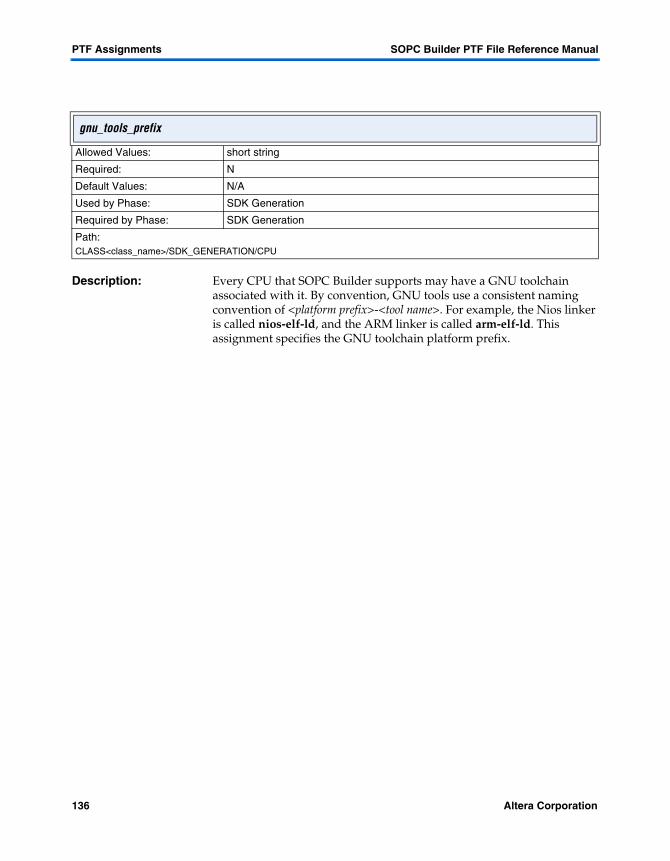
PTF Assignments SOPC Builder PTF File Reference Manual
Description: Every CPU that SOPC Builder supports may have a GNU toolchain associated with it. By convention, GNU tools use a consistent naming convention of <platform prefix>-<tool name>. For example, the Nios linker is called nios-elf-ld, and the ARM linker is called arm-elf-ld. This assignment specifies the GNU toolchain platform prefix.
gnu_tools_prefix
Allowed Values: short string
Required: N
Default Values: N/A
Used by Phase: SDK Generation
Required by Phase: SDK Generation
Path:CLASS<class_name>/SDK_GENERATION/CPU
136 Altera Corporation

SOPC Builder PTF File Reference Manual PTF Assignments
4
Assignments
Description: This assignment indicates whether this slave has a base address. SOPC Builder GUI uses this setting during System Configuration to determine whether to assign an address to this slave and perform address validation on this slave. The GUI will also display a hash pattern in the address column for slaves that have Has_Base_Address = 0. An example of a slave that does not have a base address is an IRQ-only slave (e.g., ARM Stripe interrupt slaves).
For slave interfaces that are part of a bridge, Has_Base_Address defaults to 0. For bridges where the slave interface has Has_Base_Address = 1, SOPC Builder GUI computes the Base_Address and Address_Width for both the slave and master interfaces from the components on the other side of the bridge during System Configuration. The AHB-Avalon Bridge is an example of this.
The computation of Base_Address and Address_Width for these bridges is fairly complex. First, the Base_Address is determined from the component with the lowest address and the Address_Span is calculated from the end address of the component with the highest address. This span is the Address_Span of the bridge. If this span is less than Minimum_Span, we set Address_Span to Minimum_Span. Now we go back and make sure that the Base_Address of the bridge aligns with the Address_Span.
Has_Base_Address
Allowed Values: 0
1
Required: N
Default Values: 1
Used by Phase: System ConfigurationSystem Generation
Required by Phase: System Configuration
Path:SYSTEM <system_name>/MODULE <module_name>/SLAVE <slave_name>/SYSTEM_BUILDER_INFO
Altera Corporation 137
PTF Assignments SOPC Builder PTF File Reference Manual
There is one further complexity in this calculation pertaining to tri-state buses. For convenience, we treat components on the tri-state bus a little differently when computing the Base_Address and Address_span of the AHB-Avalon Bridge. If the AHB-Avalon Bridge masters a tri-state bridge, we only include the components from the tri-state bridge that are addressable in the range of the AHB master. This permits the designer to continue using just one tri-state bus (which may be required in hardware) and to not be forced to add a separate tri-state bus for components that are not accessible to the AHB master. However this special handling also requires the use of Connection_Limit= 1 on the AHB slave interface on the bridge to prevent any ambiguity of different address ranges from different AHB masters. See “Connection_Limit’ on page 117 for further details.
138 Altera Corporation

SOPC Builder PTF File Reference Manual PTF Assignments
4
Assignments
Description: Has_IRQ indicates whether or not this SLAVE interface has an interrupt-request output port. This assignment is used by the SOPC Builder GUI to display the address map table, which also includes interrupt information. Slaves with Has_IRQ = 1 are displayed differently in the address-map table than slaves with Has_IRQ = 0. Because Has_IRQ controls how a SLAVE is displayed in the GUI, it must be valid by system-configuration time. Has_IRQ must be set during the Add/Edit phase.
Slaves which have Has_IRQ = 1 must also have a valid IRQ_Number assignment set before system-generation time.
Slaves which have Has_IRQ = 1 must also have an output-port of type irq in their PORT_WIRING section before system-generation time.
It may appear that the Has_IRQ boolean setting is redundant with the presence of an irq-type output port in a slave’s PORT_WIRING section.These settings are separate so that a SLAVE can be properly-displayed in the
GUI (via this setting) prior to its PORT_WIRING section being created (by, for example, the module’s Generator_Program).
A single SLAVE can have a maximum of one irq output (i.e., one pin of type irq in its PORT_WIRING section). MODULEs which produce more than one irq output must have multiple SLAVE interfaces. It is legal to have a SLAVE interface with only an irq-output and no other signals. This allows MODULEs to have an unlimited number of irq outputs as long as they create one SLAVE interface per irq. An example follows.
Has_IRQ
Allowed Values: 1
0
Required: N
Default Values: N/A
Used by Phase: SOPC Builder GUISDK GenerationBus Generation
Required by Phase: System Configuration Path:SYSTEM <system_name>/MODULE <module_name>/Slave <slave_name>/SYSTEM_BUILDER_INFO
Altera Corporation 139
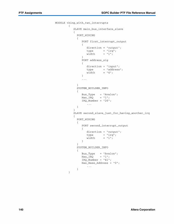
PTF Assignments SOPC Builder PTF File Reference Manual
MODULE thing_with_two_interrupts { SLAVE main_bus_interface_slave { PORT_WIRING { PORT first_interrupt_output { direction = "output"; type = "irq"; width = "1"; } PORT address_sig { direction = "input"; type = "address"; width = "4"; } ... } SYSTEM_BUILDER_INFO { Bus_Type = "Avalon"; Has_IRQ = "1"; IRQ_Number = "26"; ... } } SLAVE second_slave_just_for_having_another_irq { PORT_WIRING { PORT second_interrupt_output { direction = "output"; type = "irq"; width = "1"; } } SYSTEM_BUILDER_INFO { Bus_Type = "Avalon"; Has_IRQ = "1"; IRQ_Number = "41"; Has_Base_Address = "0"; ... } }
140 Altera Corporation

SOPC Builder PTF File Reference Manual PTF Assignments
4
Assignments
Description: SOPC Builder generates plain text HDL implementations for the top-level system module, all of the master/slave interconnection (bus) logic, and the generated test bench. SOPC Builder can generate either VHDL or Verilog, depending on the value of this assignment.
In addition to the system-level components (top module, test bench, and interconnect logic), some library components can also be generated in the user’s preference of VHDL or Verilog. In particular, many of the Avalon library components included with the Nios CPU (and the Nios CPU itself) are generated "bi-lingually."
There is no requirement for a component author to support both VHDL and Verilog implementations. It is perfectly legitimate to create an SOPC Builder library component which is implemented in only VHDL or Verilog, but not both. Users’ preferences in this matter are strong, however, and there are obvious market advantages to supporting both languages if possible or feasible.
hdl_language
Allowed Values: VerilogVHDL
Required: Y
Default Values: N/A
Used by Phase: Bus GenerationModule Generation
Required by Phase: System Generation
Path:SYSTEM <system_name>/WIZARD_SCRIPT_ARGUMENTS
Altera Corporation 141

PTF Assignments SOPC Builder PTF File Reference Manual
Description: This assignment set the number of clock cycles between when the write pulse deasserts and when the chipselect deasserts. If set to half_clock, then the write pulse will deassert one-half cycle before the chipselect deasserted. Only half-clock and full, integer numbers are supported (e.g., no 1 and half_clock). Writable asynchronous memories require this assignment to be set to a non-zero value.
Hold_Time is analogous to Setup_Time. While Hold_Time controls the number of inserted wait cycles at the end of a read or write, Setup_Time controls the number of inserted cycles at the beginning of a read or write.
A system may not have a Hold_Time (nor Setup_Time for that matter) while using peripheral-controlled wait states (Read_Wait_States or Write_Wait_States is set to peripheral_controlled).
Hold_Time
Allowed Values: 0 – 256half_clock
Required: N
Default Values: 0
Used by Phase: System Generation
Required by Phase: System Generation
Path:SYSTEM <system_name>/MODULE <module_name>/SLAVE<slave_name>/SYSTEM_BUILDER_INFO
142 Altera Corporation

SOPC Builder PTF File Reference Manual PTF Assignments
4
Assignments
Description: This assignment controls whether or not the system generator will instantiate this module within the system. If set to 1, the system generator will instantiate the module/entity within the system. If set to 0, the system will export all the modules pins to the top level and it will be the responsibility of the designer to wire up his/her logic to the exported pins.
For most components, this value is defined in the class.ptf. However, when importing HDL from the User Defined Interface Wizard, the user can select whether or not to instantiate their imported design in the system.
Instantiate_In_System_Module
Allowed Values: 0
1
Required: N
Default Values: 1
Used by Phase: System Bus Generation
Required by Phase: System Generation
Path:SYSTEM <system_name>/MODULE <module_name>/SYSTEM_BUILDER_INFO
Altera Corporation 143
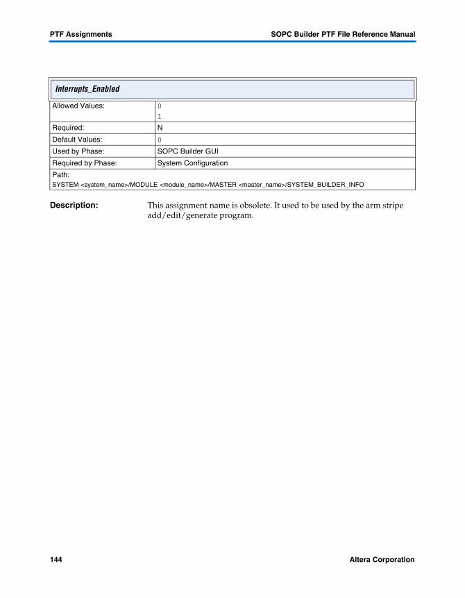
PTF Assignments SOPC Builder PTF File Reference Manual
Description: This assignment name is obsolete. It used to be used by the arm stripe add/edit/generate program.
Interrupts_Enabled
Allowed Values: 0
1
Required: N
Default Values: 0
Used by Phase: SOPC Builder GUI
Required by Phase: System Configuration
Path:SYSTEM <system_name>/MODULE <module_name>/MASTER <master_name>/SYSTEM_BUILDER_INFO
144 Altera Corporation
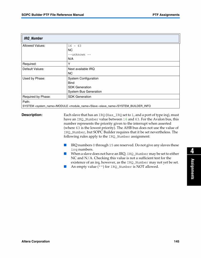
SOPC Builder PTF File Reference Manual PTF Assignments
4
Assignments
Description: Each slave that has an IRQ (Has_IRQ set to 1, and a port of type irq), must have an IRQ_Number value between 16 and 63. For the Avalon bus, this number represents the priority given to the interrupt when asserted (where 63 is the lowest priority). The AHB bus does not use the value of IRQ_Number, but SOPC Builder requires that it be set nevertheless. The following rules apply to the IRQ_Number assignment:
� IRQ numbers 0 through 15 are reserved. Do not give any slaves these irq numbers.
� When a slave does not have an IRQ, IRQ_Number may be set to either NC and N/A. Checking this value is not a sufficient test for the existence of an irq, however, as the IRQ_Number may not yet be set.
� An empty value ("") for IRQ_Number is NOT allowed.
IRQ_Number
Allowed Values: 16 – 63
NC--unknown --
N/A
Required: Y
Default Values: Next available IRQ NC
Used by Phase: System ConfigurationBindSDK GenerationSystem Bus Generation
Required by Phase: SDK Generation
Path:SYSTEM <system_name>/MODULE <module_name>/Slave <slave_name>/SYSTEM_BUILDER_INFO
Altera Corporation 145

PTF Assignments SOPC Builder PTF File Reference Manual
Description: For masters that may accept multiple IRQs (port of type irq with width > 1), this assignment describes the method to assign the slave IRQs to the master IRQ bus. This assignment is currently ONLY used for AHB bus generation.
Avalon IRQs always exhibit the same behavior: Master irqs may only be one bit wide, all slave irq ports are ORed into the master’s irq, and the highest priority IRQ_Number appears on the irq_number port. Avalon masters and slaves will ignore the IRQ_Scheme setting.
AHB IRQs have several defined behaviors. The simplest of these, and the only one currently supported, is the "individual_requests" behavior, whereby each bit of the master’s irq bus is individually assigned to one and only one slave irq. Slave irqs may be assigned to more than one bit of the master’s irq.
SOPC Builder is instructed on which slaves connect to which master by the IRQ_MAP section. If the IRQ_MAP section exists, then SOPC Builder will wire up the interrupts according to its assignments in the System Bus Generation phase. Otherwise, the attached slave lowest IRQ number (highest priority) gets wired up to the smallest index of the master irq port, the next IRQ number to the second master irq port bit, and so on, until all slaves are connected or the master irq bus is completely assigned. If more slaves are connected than the width of the master’s irq bus, then the lowest priority interrupts remain unconnected.
1 At present, individual_requests is the only allowed value for IRQ_Scheme.
Irq_Scheme
Allowed Values: individual_requests
Required: N
Default Values: individual_requests
Used by Phase: BindSDK GenerationSystem Bus Generation
Required by Phase: SDK Generation
Path:SYSTEM <system_name>/MODULE <module_name>/MASTER <master_name>/SYSTEM_BUILDER_INFO
146 Altera Corporation

SOPC Builder PTF File Reference Manual PTF Assignments
4
Assignments
Description: This assignment, as with all the assignments in the IRQ_MAP section, associates the individual bits of the master’s IRQ bus to individual IRQ signals from slaves.
irq0 (and irq1, irq2, ... , irqN)
Allowed Values: N/C<module_name>/<slave_name>
Required: N
Default Values: "" (empty string)
Used by Phase: AHB Bus Generation
Required by Phase: AHB Bus Generation
Path:SYSTEM <system_name>/MODULE <module_name>/MASTER <master_name>/SYSTEM_BUILDER_INFO/IRQ_MAP
Altera Corporation 147

PTF Assignments SOPC Builder PTF File Reference Manual
Description: This assignment indicates whether the base address for this slave can be edited. It is only applicable for slaves that have a base address. When an address is not editable, it is represented in the GUI by having the address displayed in regular text instead of bold. In addition, the Auto-Address feature will not try to reassign addresses of any slaves where Is_Base_Editable = 0.
This assignment allows the Component Author, or the Add/Edit programs to assign a fixed address to a slave that cannot be modified by the SOPC Builder GUI during System Configuration. This is currently used by the ARM Add/Edit program for the ARM Stripe interface. It sets the Base_Address to the address set in the ARM wizard, and sets Is_Base_Editable = 0. Bridges that have Has_Base_Address = 1 also have Is_Base_Editable = 0 because the SOPC Builder GUI computes the Base_Address and Address_Width from the components connected to the bridge. The user is not permitted to edit the Base_Address of these components.
Is_Base_Editable
Allowed Values: 0
1
Required: N
Default Values: 1
Used by Phase: System Configuration
Required by Phase: System Configuration
Path:SYSTEM <system_name>/MODULE <module_name>/SLAVE <slave_name>/SYSTEM_BUILDER_INFO
148 Altera Corporation

SOPC Builder PTF File Reference Manual PTF Assignments
4
Assignments
Description: Is_Base_Locked = 1 indicates that the Base_Address for this slave has been locked and may not be edited until it is unlocked. This is similar to Is_Base_Editable, except that it can be toggled on and off through the GUI. When an address is locked, a little lock icon is displayed in the address cell next to the address. The address itself is displayed in regular text instead of bold to indicate it cannot be edited. As with Is_Base_Editable, the Auto-Address feature will not try to reassign addresses of any slaves where Is_Base_Locked = 1.
Is_Base_Locked
Allowed Values: 0
1
Required: N
Default Values: 0
Used by Phase: System Configuration
Required by Phase: System Configuration
Path:SYSTEM <system_name>/MODULE <module_name>/SLAVE <slave_name>/SYSTEM_BUILDER_INFO
Altera Corporation 149

PTF Assignments SOPC Builder PTF File Reference Manual
Description: This assignment indicates that this module is a bridge. It is used by the SOPC Builder GUI primarily as a assignment from the MODULE_DEFAULTS section of the class.ptf to categorize this component in the module pool. It is also used by the Bus Type column in the module table in order to indicate that the module bridges from one bus type to another. See description for Bridges_To for more information about special handling on bridges.
Is_Bridge
Allowed Values: 0
1
Required: N
Default Values: 0
Used by Phase: SOPC Builder GUI
Required by Phase: SDK/DHDL Generation
Path:SYSTEM <system_name>/MODULE <module_name>/SYSTEM_BUILDER_INFO
150 Altera Corporation

SOPC Builder PTF File Reference Manual PTF Assignments
4
Assignments
Description: This assignment indicates whether this module is collapsed or expanded in the table. It is used only by the SOPC Builder GUI for display purposes. When a module is expanded, each slave and master interface is represented in its own row under the module. This display mode allows the user to see the setting of each column for each slave and master interface. When a module is collapsed, only the module is represented. For collapsed modules that have only 1 slave interface, all of the parameters of that interface (e.g., Base, End, IRQ, master connections) are displayed on the module.
Is_Collapsed
Allowed Values: 0
1
Required: N
Default Values: 1
Used by Phase: System Configuration
Required by Phase: System Configuration
Path:SYSTEM <system_name>/MODULE <module_name>/SYSTEM_BUILDER_INFO/View
Altera Corporation 151

PTF Assignments SOPC Builder PTF File Reference Manual
Description: This assignment indicates whether this module is collapsed or expanded in the module table. It is used only by the SOPC Builder GUI for display purposes. When a module is expanded, each slave and master interface is represented in its own row under the module. This display mode allows the user to see the setting of each column for each slave and master interface. When a module is collapsed, only the module is represented. For collapsed modules that have only 1 slave interface, all of the parameters of that interface (e.g., Base, End, IRQ, master connections) are displayed on the module.
Is_CPU
Allowed Values: 01
Required: N
Default Values: 1
Used by Phase: SOPC Builder GUI
Required by Phase: SDK/HDL Generation
Path:SYSTEM <system_name>/MODULE <module_name>/SYSTEM_BUILDER_INFO
152 Altera Corporation

SOPC Builder PTF File Reference Manual PTF Assignments
4
Assignments
Description: This assignment indicates that this master interface is a data master. It is used by SOPC Builder GUI to issue warnings for curious master-slave connections.
For a module that has both a data master and an instruction master (e.g., Nios), the GUI will issue a warning if the instruction master is connected to a given slave and not the data master. This is not illegal, but it is almost always not what the user wanted. If there is any data stored in that slave, it will not be accessible to the data master unless the data master is also connected to the slave.
Is_Data_Master
Allowed Values: 01
Required: N
Default Values: 0
Used by Phase: System Configuration
Required by Phase: System Configuration
Path:SYSTEM <system_name>/MODULE <module_name>/MASTER <master_name>/SYSTEM_BUILDER_INFO
Altera Corporation 153

PTF Assignments SOPC Builder PTF File Reference Manual
Description: For modules, this assignment is used to enable and disable entire modules. It is controlled through the Use checkbox in the module table. When a module is disabled, it is grayed out in the table and all of the master and slave interfaces become unavailable for inclusion in the system (i.e., Master-Slave connections cannot be made, the interfaces may not be selected on the binding pages). The module is ignored during all of the generation phases.
For slaves and masters, this assignment is used to include or exclude individual interfaces. If an interface is disabled, it does not appear in the module table and essentially does not exist, from the perspective of the GUI. This assignment is made only by the Add or Edit programs, and is read–only to the SOPC Builder. This allows for components that have multiple configurations with different interfaces. The configuration of interfaces is managed through the Add/Edit programs.
Is_Enabled
Allowed Values: 01
Required: Y
Default Values: 1
Used by Phase: System ConfigurationSDK GenerationSystem Generation
Required by Phase: System Configuration
Path:SYSTEM <system_name>/MODULE <module_name> /MASTER <master_name>/SYSTEM_BUILDER_INFOSYSTEM <system_name>/MODULE <module_name> /SLAVE <slave_name>/SYSTEM_BUILDER_INFOSYSTEM <system_name>/MODULE <module_name> /SYSTEM_BUILDER_INFO
154 Altera Corporation

SOPC Builder PTF File Reference Manual PTF Assignments
4
Assignments
Description: This assignment indicates that this master interface is an instruction master. It is used by the SOPC Builder GUI, along with Is_Memory_Device and Is_Bridge, to assign default master-slave connections when components are added. If a master has Is_Instruction_Master = 1, it is automatically connected to slaves that have Is_Memory_Device = 1 or Is_Bridge = 1. Instruction masters are not connected by default to any other kind of slaves.
It is also used to issue warnings for curious master-slave connections. For a module that has both a data master and an instruction master(e.g., Nios), the GUI will issue a warning if the instruction master is connected to a given slave and not the data master. See Is_Data_Master for more details on this warning.
Is_Instruction_Master
Allowed Values: 01
Required: N
Default Values: 0
Used by Phase: System Configuration
Required by Phase: System Configuration
Path:SYSTEM <system_name>/MODULE <module_name>/MASTER <master_name>/SYSTEM_BUILDER_INFO
Altera Corporation 155

PTF Assignments SOPC Builder PTF File Reference Manual
Description: This assignment is used by the SOPC Builder GUI to make informed decisions about what master-slave connections to make by default. When a new slave interface is added that has Is_Memory_Device = 1, it is automatically connected to both instruction and data masters of the CPU, if they exist. Slave interfaces that do not have Is_Memory_Device = 1 are connected only to the data master.
This assignment is also used by the binding page for Nios to identify which slave interfaces are appropriate to be selected for program and data memory.
Is_Memory_Device
Allowed Values: 01
Required: N
Default Values: 0
Used by Phase: System ConfigurationSDK Generation
Required by Phase: System Configuration
Path:SYSTEM <system_name>/MODULE <module_name>/SLAVE <slave_name>/SYSTEM_BUILDER_INFOSYSTEM <system_name>/MODULE <module_name>/SYSTEM_BUILDER_INFO
156 Altera Corporation
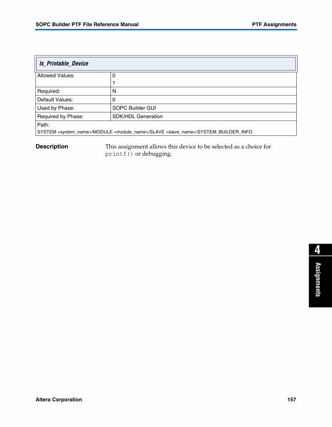
SOPC Builder PTF File Reference Manual PTF Assignments
4
Assignments
Description This assignment allows this device to be selected as a choice for printf() or debugging.
Is_Printable_Device
Allowed Values: 01
Required: N
Default Values: 0
Used by Phase: SOPC Builder GUI
Required by Phase: SDK/HDL Generation
Path:SYSTEM <system_name>/MODULE <module_name>/SLAVE <slave_name>/SYSTEM_BUILDER_INFO
Altera Corporation 157

PTF Assignments SOPC Builder PTF File Reference Manual
Description: Shared ports of similar type which have the same avalon_tristate master will share the same pins off the chip. If the ports are of different widths, the low bits of the port will be shared. For more detailed information on type assignments, see "type" on page 210.
Is_shared
Allowed Values: 01
Required: N
Default Values: 0
Used by Phase: Avalon_Tristate_Bus_Generation
Required by Phase: SDK/HDL Generation
Path:SYSTEM <system_name>/MODULE <module_name>/SLAVE <slave_name>/PORT_WIRING/PORT <port_name>
158 Altera Corporation

SOPC Builder PTF File Reference Manual PTF Assignments
4
Assignments
Description: This assignment is used by the SOPC Builder GUI to determine whether or not to display a module, slave port, or master port in the system builder module pool table.This is used to prevent custom instructions modules, as well as custom instruction master ports, from appearing in the system builder pool table.
f See the SOPC Builder Data Sheet for more information about the system builder module table and AN188 – Custom Instructions for the Nios Embedded Processor for custom instruction details at http://www.altera.com/literature/lit-nio.html.
Is_Visible
Allowed Values: 01
Required: Y
Default Values: 1
Used by Phase: SOPC Builder GUI
Required by Phase: System Configuration
Path:SYSTEM <system_name>/MODULE <module_name>/MASTER <master_name>/SYSTEM_BUILDER_INFOSYSTEM <system_name>/MODULE <module_name>/SLAVE <slave_name>/SYSTEM_BUILDER_INFOSYSTEM <system_name>/MODULE <module_name>/SYSTEM_BUILDER_INFO
Altera Corporation 159

PTF Assignments SOPC Builder PTF File Reference Manual
Description: This optional assignment specifies a JAR file to appended to Java’s class-path for Add/Edit Programs. When custom Java class(es) are used in conjunction with WIZARD_UI sections to define a user interface, it is necessary to specify the Jar_File which contains the Java class(es). When a Jar_File is specified, the additional command line parameter below is passed to the add/edit program.
--sopc_jar_file=<Jar_File assignment>
Jar_File
Allowed Values: java (*.jar)"" (empty string)
Required: N
Default Values: "" (empty string)
Used by Phase: Add Edit
Required by Phase: Component Authoring
Path:CLASS <class_name>/ASSOCIATED_FILES
160 Altera Corporation

SOPC Builder PTF File Reference Manual PTF Assignments
4
Assignments
Description: This setting partially specifies the contents for a memory-oriented module. Depending on the value of Kind, one of the other settings, Build_Info, Command_Info, Textfile_Info, or String_Info will be used to further specify the contents.
The value germs means "build a GERMS monitor for this module; the value blank means "build a table of zeroes the same size as this module"; the value test_code means assemble a minimal bit of code based upon other components’ test routines for this module.
Kind
Allowed Values: blankgermstest_codebuildcommandfilestring
Required: Y
Default Values: "" (empty string)
Used by Phase: SOPC Builder
Required by Phase: SDK/HDL Generation
Path:SYSTEM <system_name>/MODULE <module_name>/WIZARD_SCRIPT_ARGUMENTS/CONTENTS/srec
Altera Corporation 161

PTF Assignments SOPC Builder PTF File Reference Manual
Obsolete & Ignored Assignment
Description: See the table below for using the allowed values of the leo_area assignment.
f See the Quartus II software help system for synthesis information.
leo_area
Allowed Values: 01
Required: Y
Default Values: N/A
Used by Phase: System Generation
Required by Phase: System Generation
Path:SYSTEM <system_name>/WIZARD_SCRIPT_ARGUMENTS
If Then
0 Leonardo Spectrum is given the command line option “-delay”.
1 Leonardo Spectrum is given the command line option “-area”.
162 Altera Corporation

SOPC Builder PTF File Reference Manual PTF Assignments
4
Assignments
Obsolete & Ignored Assignment
Description: See the table below for using the allowed values of the leo_flatten assignment.
f See the Quartus II software help system for synthesis information.
leo_flatten
Allowed Values: 01
Required: Y
Default Values: N/A
Used by Phase: System Generation
Required by Phase: System Generation
Path:SYSTEM <system_name>/WIZARD_SCRIPT_ARGUMENTS
If Then
0 Leonardo Spectrum is given the command line option "-hierarchy_auto".
1 Leonardo Spectrum is given the command line option "-hierarchy_flatten".
Altera Corporation 163

PTF Assignments SOPC Builder PTF File Reference Manual
Obsolete & Ignored Assignment
Description: Unsupported debugging assignment. Used to direct Leonardo Spectrum to perform more than just optimization pass 1. Tests show that passes 2-4 have little effect on SOPC Builder’s quality of results.
f See the Quartus II software help system for synthesis information.
leo_pass
Allowed Values: command line option, without leading hyphen
Required: N
Default Values: pass = {1}
Used by Phase: System Generation
Required by Phase: System Generation
Path:SYSTEM <system_name>/WIZARD_SCRIPT_ARGUMENTS
164 Altera Corporation

SOPC Builder PTF File Reference Manual PTF Assignments
4
Assignments
Description: SOPC Builder ships with a full complement of peripherals, which are freely available for use. In addition, evaluation versions of peripherals may be installed. Evaluation peripherals have full functionality, but may only be functional for a limited time after hardware configuration. These serve the purpose of letting users test IP before buying it. Finally, placeholder peripherals, which target a browser at a URL can be installed
The license assignment controls the appearance of peripherals in the System Contents tab as follows:
license
Allowed Values: fullevalnone
Required: N
Default Values: full
Used by Phase: SOPC Builder GUI
Required by Phase: Add
Path:CLASS <class_name> /USER _INTERFACE/USER_LABELS
license appearance
full green dot to left of peripheral name
eval yellow dot to left of peripheral name
none open dot to left of peripheral name
Altera Corporation 165

PTF Assignments SOPC Builder PTF File Reference Manual
Description: If Make_Memory_Model is set to 1 and the appropriate SDK contents are set in the WIZARD_SCRIPT_ARGUMENTS section, SOPC builder will generate a non-cycle accurate memory module with appropriate contents and instantiate it in the test bench. If a module generates a simulation model, this value should be set to 0 and the filename containing the simulation model should be appended to the appropriate comma-separated list.
MODULE <module_name>/HDL_INFO/Verilog_Sim_Model_Files and/orMODULE <module_name>/HDL_INFO/Vhdl_Sim_Model_Files
For detailed information, see"Verilog_Sim_Model_Files" on page 211 and "VHDL_Sim_Model_Files" on page 213.
Make_Memory_Model
Allowed Values: 01
Required: N
Default Values: 0
Used by Phase: System Generation
Required by Phase: System Generation
Path:SYSTEM <system_name>/MODULE <module_name>/SYSTEM_BUILDER_INFO
166 Altera Corporation

SOPC Builder PTF File Reference Manual PTF Assignments
4
Assignments
Description: This assignment specifies the type of arbitration. Currently percentage is the only value supported.
Example:
SYSTEM ref_32_system { MODULE timer1 { SLAVE s1 { SYSTEM_BUILDER_INFO { Master_Arbitration = "percentage"; } } } }
f See Simultaneous Multi-Mastering with the Avalon Bus Application Note 184 http://www.altera.com/literature/lit-nio.html for more information about arbitration.
Master_Arbitration
Allowed Values: Percentage
Required: N
Default Values: Percentage
Used by Phase: System Bus Generation
Required by Phase: SDK/HDKL Generation
Path:SYSTEM <system_name>/MODULE <module_name>/SLAVE <slave_name>/SYSTEM_BUILDER_INFO
Altera Corporation 167
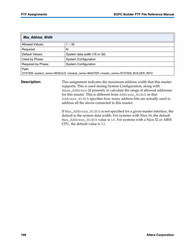
PTF Assignments SOPC Builder PTF File Reference Manual
Description: This assignment indicates the maximum address width that this master supports. This is used during System Configuration, along with Base_Address (if present), to calculate the range of allowed addresses for this master. This is different from Address_Width in that Address_Width specifies how many address bits are actually used to address all the slaves connected to this master.
If Max_Address_Width is not specified for a given master interface, the default is the system data width. For systems with Nios 16, the default Max_Address_Width value is 16. For systems with a Nios 32 or ARM CPU, the default value is 32.
Max_Address_Width
Allowed Values: 1 – 32
Required: N
Default Values: System data width (16 or 32)
Used by Phase: System Configuration
Required by Phase: System Configuration
Path:SYSTEM <system_name>/MODULE <module_name>/MASTER <master_name>/SYSTEM_BUILDER_INFO
168 Altera Corporation

SOPC Builder PTF File Reference Manual PTF Assignments
4
Assignments
Description: This assignment indicates the minimum address span that this slave can occupy. It is used exclusively for bridges where the SOPC Builder calculates the address span of the bridge from the address spans of the connected components. If the calculated span is less than Minimum_Span, Address_Span is set to Minimum_Span for both the slave and master interfaces of the bridge. It is required for masters (e.g., ARM_Stripe/ahb_master) that have a limited address granularity.
An example of this would be the ARM_stripe/ahb_master mastering an avalon UART through an AHB-Avalon Bridge. The AHB slave in the AHB-Avalon Bridge has Minimum_Span = 1024. Since the span of the UART is less than 1024, the Address_Span of the AHB slave and avalon master in the bridge are both set to 1024. See "Has_Base_Address" on page 137 for more information about the calculations of Address_Span.
Minimum_Span
Allowed Values: 0 – 2^32
Required: N
Default Values: 0
Used by Phase: System Configuration
Required by Phase: System Configuration
Path:SYSTEM <system_name>/MODULE <module_name>/SLAVE <slave_name>/SYSTEM_BUILDER_INFO
Altera Corporation 169

PTF Assignments SOPC Builder PTF File Reference Manual
Description: This parameter adds directories to the search path used by ModelSim for files included via the Verilog include directive. Each directory specified in any module’s ModelSim_Inc_Path will be added to the arguments of the vlog command within the ModelSim simulation setup file setup_sim.do, as a +incdir+ directive. Redundant ModelSim_Inc_Path values will collapse to a single +incdir+ directive.
ModelSim_Inc_Path
Allowed Values: A comma separated list of directories
Required: N
Default Values: "" (empty string)
Used by Phase: Project File Generation
Required by Phase: Project File Generation
Path:SYSTEM <system_name>/MODULE <module_name>/HDL_INFO
If Then
The example below appears in a peripheral’s PTF file section;MODULE <module name> { HDL_INFO { ModelSim_Inc_Path = "D:/lib/verilog"; }
in the definition of the ’s’ alias in setup_sim.do, the following appear as an additional argument to vlog:+incdir+D:/lib/verilog
170 Altera Corporation
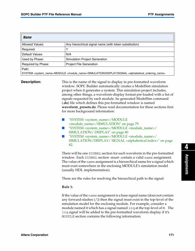
SOPC Builder PTF File Reference Manual PTF Assignments
4
Assignments
Description: This is the name of the signal to display in pre-formatted waveform window. SOPC Builder automatically creates a ModelSim simulation project when it generates a system. This simulation project includes, among other things, a waveform-display format pre-loaded with a list of signals requested by each module. he generated ModelSim command (.do) file which defines this pre-formatted window is named waveform_presets.do. Please read documentation for these sections first for more background information:
� "SYSTEM <system_name>/MODULE <module_name>/SIMULATION" on page 79
� "SYSTEM <system_name>/MODULE <module_name>/ SIMULATION/ DISPLAY" on page 80
� "SYSTEM <system_name>/MODULE <module_name>/ SIMULATION/DISPLAY/ SIGNAL <alphabetical index>" on page 82.
There will be one SIGNAL section for each waveform in the pre-formatted window. Each SIGNAL section -must- contain a valid name assignment. The value of the name assignment is a hierarchical name for a signal which must exist somewhere in the enclosing MODULE’s simulation model (usually HDL implementation).
These are the rules for resolving the hierarchical path to the signal:
Rule 1:
If the value of the name assignment is a base signal name (does not contain any forward-slashes (/)) then the signal must exist in the top-level of the simulation model for the enclosing module. For example, consider a module named M which has a signal named irq at the top-level of M. The irq signal will be added to the pre-formatted waveform display if M’s MODULE section contains the following information:
Name
Allowed Values: Any hierarchical signal name (with token substitution)
Required: Y
Default Values: N/A
Used by Phase: Simulation Project Generation
Required by Phase: Project File Generation
Path:SYSTEM <system_name>/MODULE <module_name>/SIMULATION/DISPLAY/SIGNAL <alphabetical_ordering_name>
Altera Corporation 171

PTF Assignments SOPC Builder PTF File Reference Manual
MODULE M { ... other module data... SIMULATION { DISPLAY { SIGNAL ignored_signal_section_name { name = "irq"; } } } }
Hierarchical paths are taken, by default, as starting from the top-level of the enclosing module. For example, consider a signal internal_state which exists in the FSM sub-module in M’s simulation model. To display this signal, M’s MODULE section would look like this:
MODULE M { ... other module data... SIMULATION { DISPLAY { SIGNAL ignored_signal_section_name { name = "FSM/internal_state"; } } } }
Rule 2:
If the literal string __MODULE_PATH__ appears anywhere in the name assignment-value, it is replaced by this string:
/test_bench/DUT/the_<module_name>
This value is used during the Project File Generation phase, and can often be set during the Component Authoring phase (because, in general, the list of "interesting" signals, and how they should be displayed, is known when each module is created).
172 Altera Corporation

SOPC Builder PTF File Reference Manual PTF Assignments
4
Assignments
Description: This assignment is the name that is used to identify this component. It is name that appears in the module pool. It also appears in the module table in the Description column for each instance of this component.
Example:
USER_INTERFACE { USER_LABELS { name="UART (RS-232 serial port)"; } }
name
Allowed Values: Text
Required: Y
Default Values: N/A
Used by Phase: System Assembly
Required by Phase: Component Authoring
Path:CLASS <class_name>/USER_INTERFACE/USER_LABELS
Altera Corporation 173

PTF Assignments SOPC Builder PTF File Reference Manual
Description: This assignment indicates the width of the Module Name column in the module table. It is used by the SOPC Builder GUI to maintain column widths in the module table across SOPC Builder sessions. If it is not present, the Module Name column uses the default column width.
name_column_width
Allowed Values: Integer value
Required: N
Default Values: "" (empty string)
Used by Phase: System Configuration
Required by Phase: System Configuration
Path:SYSTEM <system_name>/WIZARD_SCRIPT_ARGUMENTS
174 Altera Corporation

SOPC Builder PTF File Reference Manual PTF Assignments
4
Assignments
Description: This assignment is a comma-separated list of files which use the verilog PLI interface. When SOPC Builder generates the modelsim file setup_sim.do in the simulation directory, it will set the -PLI flag for each <file> specified. This works for both Verilog and VHDL ModelSim simulation. The VHDL Modelsim PLI interface only works with the ModelSim SE edition. VHDL users who try to use the -PLI setting with the Altera OEM version of ModelSim will crash ModelSim with no warning.
Example:
SYSTEM sys { MODULE ARM_Stripe { HDL_INFO { PLI_Files = "D:/Quartus/eda/sim_lib/excalibur/stripe_model_nt/modelgen/manager/WinNT/MM/mti_modelsim_verilog/libmgmm.so"; } } }
PLI_Files
Allowed Values: A comma separated list of directories
Required: N
Default Values: "" (empty string)
Used by Phase: Project File Generation
Required by Phase: Project File Generation
Path:SYSTEM <system_name>/MODULE <module_name>/HDL_INFO
Altera Corporation 175

PTF Assignments SOPC Builder PTF File Reference Manual
Description: This assignment is a comma separated list of precompiled library directories that will be referenced by ModelSim. Each element of the comma-separated list is passed to vsim as a library path, using the -Lf switch. This value is intended to be used to point to precompiled libraries, which are commonly included in a distribution of encrypted IP.
Precompiled_Simulation_Library_Files
Allowed Values: A comma separated list of directories
Required: N
Default Values: "" (empty string)
Used by Phase: Project File Generation
Required by Phase: Project File Generation
Path:SYSTEM <system_name>/MODULE <module_name>/HDL_INFO
176 Altera Corporation
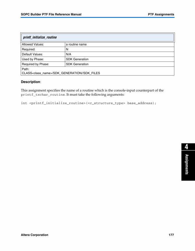
SOPC Builder PTF File Reference Manual PTF Assignments
4
Assignments
Description:
This assignment specifies the name of a routine which is the console-input counterpart of the printf_txchar_routine. It must take the following arguments:
int <printf_initialize_routine>(<c_structure_type> base_address);
printf_initialize_routine
Allowed Values: a routine name
Required: N
Default Values: N/A
Used by Phase: SDK Generation
Required by Phase: SDK Generation
Path:CLASS<class_name>/SDK_GENERATION//SDK_FILES
Altera Corporation 177

PTF Assignments SOPC Builder PTF File Reference Manual
Description:
This assignment specifies the name of a routine which is the console-input counterpart to the printf_txchar_routine. It must take the following arguments:
int <printf_rxchar_routine>(<c_structure_type> base_address);
This assignment must return either a character from the peripheral, or –1 if no character is waiting.
printf_rxchar_routine
Allowed Values: a routine name
Required: N
Default Values: N/A
Used by Phase: SDK Generation
Required by Phase: SDK Generation
Path:CLASS<class_name>/SDK_GENERATION//SDK_FILES
178 Altera Corporation

SOPC Builder PTF File Reference Manual PTF Assignments
4
Assignments
Description:
Some peripheral, including but not limited to UARTS, are viable targets for the standard C routine printf(). SOPC Builder lets you choose which such device is used for printf output. This assignment specifies the name of a routine for printing single characters to the peripheral. This routine must be present in this peripheral’s library and a prototype in the file specified by the c_structure_file assignment. The routine must take the following arguments:
void <printf_txchar_routine>(int character, <c_structure_type> base_address);
printf_txchar_routine
Allowed Values: routine name
Required: N
Default Values: N/A
Used by Phase: SDK Generation
Required by Phase: SDK Generation
Path:CLASS<class_name>/SDK_GENERATION//SDK_FILES
Altera Corporation 179

PTF Assignments SOPC Builder PTF File Reference Manual
Description: This assignment gives a priority value to each master that masters a given slave. It is viewable/editable from View|Show Arbitration Priorities menu. Under percentage arbitration (see "Master_Arbitration" on page 167), priority indicates number of shares which a master receives. For example, below is the following slave_SBI section.
... SLAVE my_slave { ...other SLAVE info... SYSTEM_BUILDER_INFO { ... other system builder info... MASTERED_BY module_one/master_one { priority = "1"; } MASTERED_BY module_two/master_two { priority = "21"; } } }
If master_one and master_two both accessed my_slave at the same time, master_one would be granted the slave 1 time out of 22 conflicts and master_two would be granted the slave 21 times out of 22 conflicts.
priority
Allowed Values: 0 – 100
Required: Y
Default Values: 01
Used by Phase: SOPC Builder GUI
Required by Phase: SDK/HDL Generation
Path:SYSTEM <system_name>/MODULE <module_name>/SLAVE <slave_name>/SYSTEM_BUILDER_INFO/MASTERED_BY <master_name>
180 Altera Corporation

SOPC Builder PTF File Reference Manual PTF Assignments
4
Assignments
A conflict occurs when both masters initiate an access to the slave on the same clock-cycle, or when one of the masters initiates an access while the slave is currently granted to the other master. Access to Avalon slaves is renegotiated on an access-by-access basis. See the Avalon Bus Specification Reference Manual at http://www.altera.com/literature/lit-nio.html for more details. When there is no conflict (i.e., when only one master is accessing the slave) the slave is always immediately granted to whichever master requested it.
The SOPC Builder GUI provides controls for viewing and editing arbitration priorities (select Show Arbitration Priorities from the View menu). This information is set at System Assembly time, and is not (cannot) be known at Component Authoring time.
Altera Corporation 181
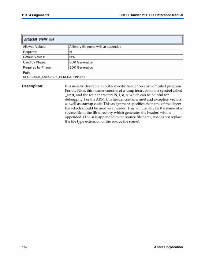
PTF Assignments SOPC Builder PTF File Reference Manual
Description: It is usually desirable to put a specific header on any compiled program. For the Nios, this header consists of a jump instruction to a symbol called _start, and the four characters N, i, o, s, which can be helpful for debugging. For the ARM, this header contains reset and exception vectors, as well as startup code. This assignment specifies the name of the object file which should be used as a header. This will usually be the name of a source file in the lib directory which generates the header, with .o appended. (The .o is appended to the source file name; it does not replace the file type extension of the source file name).
program_prefix_file
Allowed Values: A library file name with .o appended
Required: N
Default Values: N/A
Used by Phase: SDK Generation
Required by Phase: SDK Generation
Path:CLASS<class_name>/SDK_GENERATION/CPU
182 Altera Corporation

SOPC Builder PTF File Reference Manual PTF Assignments
4
Assignments
Description: This assignment indicates the name of the company that produced this component. It is intended to be used to provide more detailed information about each core in the module pool.
provider
Allowed Values: Text
Required: N
Default Values: N/A
Used by Phase: N/A
Required by Phase: Component Authoring
Path:CLASS <class_name>/USER_INTERFACE/USER_LABELS
Altera Corporation 183
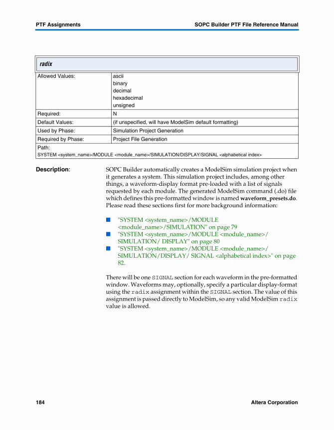
PTF Assignments SOPC Builder PTF File Reference Manual
Description: SOPC Builder automatically creates a ModelSim simulation project when it generates a system. This simulation project includes, among other things, a waveform-display format pre-loaded with a list of signals requested by each module. The generated ModelSim command (.do) file which defines this pre-formatted window is named waveform_presets.do. Please read these sections first for more background information:
� "SYSTEM <system_name>/MODULE <module_name>/SIMULATION" on page 79
� "SYSTEM <system_name>/MODULE <module_name>/ SIMULATION/ DISPLAY" on page 80
� "SYSTEM <system_name>/MODULE <module_name>/ SIMULATION/DISPLAY/ SIGNAL <alphabetical index>" on page 82.
There will be one SIGNAL section for each waveform in the pre-formatted window. Waveforms may, optionally, specify a particular display-format using the radix assignment within the SIGNAL section. The value of this assignment is passed directly to ModelSim, so any valid ModelSim radix value is allowed.
radix
Allowed Values: ascii binarydecimalhexadecimalunsigned
Required: N
Default Values: (if unspecified, will have ModelSim default formatting)
Used by Phase: Simulation Project Generation
Required by Phase: Project File Generation
Path:SYSTEM <system_name>/MODULE <module_name>/SIMULATION/DISPLAY/SIGNAL <alphabetical index>
184 Altera Corporation
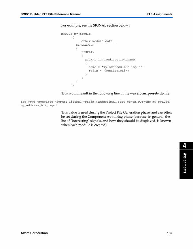
SOPC Builder PTF File Reference Manual PTF Assignments
4
Assignments
For example, see the SIGNAL section below :
MODULE my_module { ...other module data... SIMULATION { DISPLAY { SIGNAL ignored_section_name { name = "my_address_bus_input"; radix = "hexadecimal"; } } } }
This would result in the following line in the waveform_presets.do file:
add wave -noupdate -format Literal -radix hexadecimal/test_bench/DUT/the_my_module/ my_address_bus_input
This value is used during the Project File Generation phase, and can often be set during the Component Authoring phase (because, in general, the list of "interesting" signals, and how they should be displayed, is known when each module is created).
Altera Corporation 185

PTF Assignments SOPC Builder PTF File Reference Manual
Description: Avalon bus generation in SOPC Builder 2.5 and higher support read latency. Read_Latency is not the same thing as Read_Wait_States. A slave may have both. While Read_Wait_States tells how long the master must hold its read request, Read_Latency calculates how many cycles will pass until the value requested is ready.
Masters who can handle read latency (i.e., masters with a readdatavalid pin) need only hold their read request until their wait pin is deasserted and can ask for additional data while previous requests for data are pipelined. When the latent data is available, Avalon Bus Logic will assert the master’s readdatavalid pin. When the readdatavalid pin is asserted, masters must accept the read data.
For Masters who do not have a readdatavalid pin, the Avalon Bus logic will force them to wait the additional Read_Latency cycles until the data from the slave is available.
f See the Avalon Bus Specification Reference Manual at http://www.altera.com/literature/lit-nio.html for more detailed information.
Read_Latency
Allowed Values: 1– 8
Required: N
Default Values: 0
Used by Phase: Avalon/Avalon Tristate-Bus Generation
Required by Phase: System Generation
Path:SYSTEM <system_name>/MODULE <module_name>/SLAVE <slave_name>/SYSTEM_BUILDER_INFO
186 Altera Corporation

SOPC Builder PTF File Reference Manual PTF Assignments
4
Assignments
Description: This assignment controls how many wait states the bus inserts between when a master reads and when the data is returned. A number indicates the number of wait cycles. The value peripheral_controlled indicates that the slave has a pin of type waitrequest (or waitrequest_n) that will indicate when a read transaction is complete. During the inserted wait states (either peripheral-controlled or predefined), the bus will assert the master’s wait port.
If either of Write_Wait_States or Read_Wait_States is set to peripheral_controlled, both reads and writes will be considered peripheral_controlled.
Read_Wait_States
Allowed Values: 0 – 255peripheral_controlled
Required: N
Default Values: 0
Used by Phase: System Bus Generation
Required by Phase: System Bus Generation
Path:SYSTEM <system_name>/MODULE <module_name>/SLAVE <slave_name>/SYSTEM_BUILDER_INFO
Altera Corporation 187
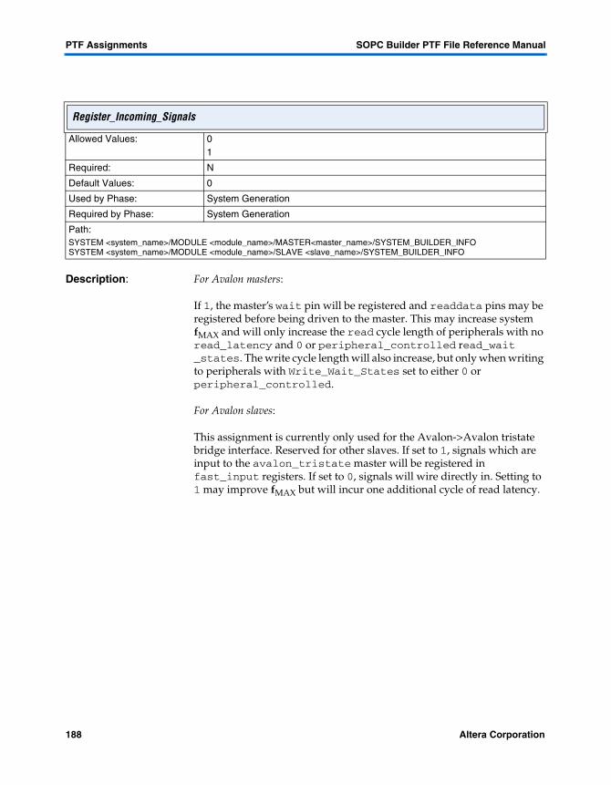
PTF Assignments SOPC Builder PTF File Reference Manual
Description: For Avalon masters:
If 1, the master’s wait pin will be registered and readdata pins may be registered before being driven to the master. This may increase system fMAX and will only increase the read cycle length of peripherals with no read_latency and 0 or peripheral_controlled read_wait _states. The write cycle length will also increase, but only when writing to peripherals with Write_Wait_States set to either 0 or peripheral_controlled.
For Avalon slaves:
This assignment is currently only used for the Avalon->Avalon tristate bridge interface. Reserved for other slaves. If set to 1, signals which are input to the avalon_tristate master will be registered in fast_input registers. If set to 0, signals will wire directly in. Setting to 1 may improve fMAX but will incur one additional cycle of read latency.
Register_Incoming_Signals
Allowed Values: 01
Required: N
Default Values: 0
Used by Phase: System Generation
Required by Phase: System Generation
Path:SYSTEM <system_name>/MODULE <module_name>/MASTER<master_name>/SYSTEM_BUILDER_INFOSYSTEM <system_name>/MODULE <module_name>/SLAVE <slave_name>/SYSTEM_BUILDER_INFO
188 Altera Corporation
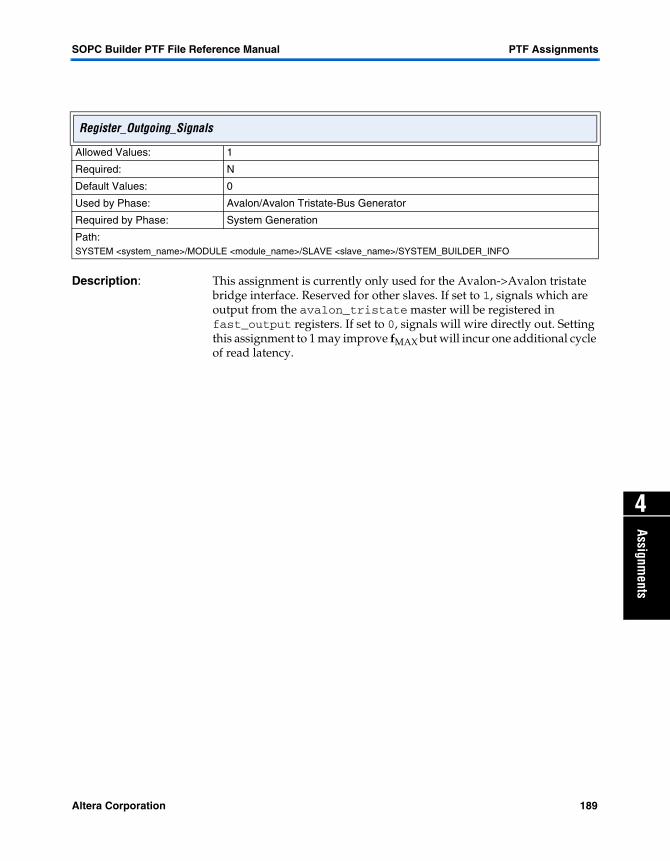
SOPC Builder PTF File Reference Manual PTF Assignments
4
Assignments
Description: This assignment is currently only used for the Avalon->Avalon tristate bridge interface. Reserved for other slaves. If set to 1, signals which are output from the avalon_tristate master will be registered in fast_output registers. If set to 0, signals will wire directly out. Setting this assignment to 1 may improve fMAX but will incur one additional cycle of read latency.
Register_Outgoing_Signals
Allowed Values: 1
Required: N
Default Values: 0
Used by Phase: Avalon/Avalon Tristate-Bus Generator
Required by Phase: System Generation
Path:SYSTEM <system_name>/MODULE <module_name>/SLAVE <slave_name>/SYSTEM_BUILDER_INFO
Altera Corporation 189

PTF Assignments SOPC Builder PTF File Reference Manual
Description: Enables the Component Author to force the selection of specific device family for this component when it is included in a system. During validation, if the SOPC Builder GUI detects the SYSTEM/WIZARD_SCRIPT_ARGUMENTS/Required_Device_Family assignment is set to a different family, it will generate an error and prevent the user from entering the System Generation phase. Multiple device families may be specified using a comma-separated list.
It is invalid to have more than one MODULE defined with different Required_Device_Family assignments. One of them will always generate and error and prevent System Generation.
Required_Device_Family
Allowed Values: device-family name (e.g., EXCALIBUR_ARM)
Required: N
Default Values: N/A
Used by Phase: Component AuthoringSystem AssemblySystem Generation
Required by Phase: System Assembly
Path: SYSTEM <system_name>/MODULE <module_name>/SYSTEM_BUILDER_INFO
190 Altera Corporation

SOPC Builder PTF File Reference Manual PTF Assignments
4
Assignments
Description: This assignment should always have the value sdk.
sdk_directory_suffix
Allowed Values: sdk
Required: Y
Default Values: sdk
Used by Phase: SDK Generation
Required by Phase: SDk Generation
Path:CLASS<class_name>/SDK_GENERATION/CPU
Altera Corporation 191

PTF Assignments SOPC Builder PTF File Reference Manual
Description: This assignment is a partial path to a directory containing files which will be added to the SDK that SOPC Builder creates for the particular CPU and toolchain. This directory may contain any or all of the following three subdirectories: inc, lib, and src. The contents of each of these subdirectories will be copied to the resulting SDK. Files outside these subdirectories are not copied. This assignment may be present in more than one SDK_FILES section; the contents of all matching SDK_FILES/sdk_files_dir directories will be copied to the resulting SDK.
sdk_files_dir
Allowed Values: partial path within component directory
Required: N
Default Values: N/A
Used by Phase: SDK Generation
Required by Phase: SDK Generation
Path:CLASS<class_name>/SDK_GENERATION//SDK_FILES
192 Altera Corporation

SOPC Builder PTF File Reference Manual PTF Assignments
4
Assignments
Description: This assignment influences the name given to a peripheral’s slave ports in the system’s custom SDK. Peripherals which have only a single slave port (the common case) can set SDK_Use_Slave_Name to 0, or omit it. Peripherals which have multiple slave ports should set SDK_Slave_Name to 1.
Rules for SDK slave name generation: the custom SDK for a system will contain a #define for each slave port’s base address, end address and size. When this assignment is set to 0, then the #define values are
na_<module_name>, na_<module_name>_end and na_<module_name>_size, respectively.
If SDK_Use_Slave_Name is set to 1, then the #define values are
na_<module_name>_<slave_name>, na_<module_name>_<slave_name>_end
and
na_<module_name>_<slave_name>_size.
Consider the following slave port within a peripheral’s PTF file section:
MODULE ARM_Stripe { SLAVE dpram_a { SYSTEM_BUILDER_INFO { SDK_Use_Slave_Name = "0"; Base_Address = "0x00000000"; Data_Width = "8"; Address_Width = "16"; Address_Alignment = "dynamic"; }
SDK_Use_Slave_Name
Allowed Values: 01
Required: N
Default Values: 0
Used by Phase: SDK Generation
Required by Phase: SDK/HDL Generation
Path:SYSTEM <system_name>/MODULE <module_name>/SLAVE <slave_name>/SYSTEM_BUILDER_INFO
Altera Corporation 193

PTF Assignments SOPC Builder PTF File Reference Manual
} }In the custom header file generated for this system, the following #define values will appear:
#define na_ARM_Stripe ((void *) 0x00000000) #define na_ARM_Stripe_end ((void *) 0x00010000) #define na_ARM_Stripe_size ((void *) 0x00010000)
Now consider a module with two slaves:
MODULE ARM_Stripe { SLAVE dpram_a { SYSTEM_BUILDER_INFO { SDK_Use_Slave_Name = "0"; Base_Address = "0x00000000"; Data_Width = "8"; Address_Width = "16"; Address_Alignment = "dynamic"; } } SLAVE dpram_b { SYSTEM_BUILDER_INFO { SDK_Use_Slave_Name = "1"; Base_Address = "0x00010000"; Data_Width = "16"; Address_Width = "15"; Address_Alignment = "dynamic"; } } }The following #define values will be created for the module’s two slaves:
#define na_ARM_Stripe_dpram_a ((void *) 0x00000000) #define na_ARM_Stripe_dpram_a_end ((void *) 0x00010000) #define na_ARM_Stripe_dpram_a_size ((void *) 0x00010000) #define na_ARM_Stripe_dpram_b ((void *) 0x00010000) #define na_ARM_Stripe_dpram_b_end ((void *) 0x00020000) #define na_ARM_Stripe_dpram_b_size ((void *) 0x00010000)
194 Altera Corporation

SOPC Builder PTF File Reference Manual PTF Assignments
4
Assignments
Description: This assignment is used by the SOPC Builder GUI to display as the tool tip for this module when the cursor is held over this module in the table. If this assignment is present, the GUI takes the name of the module (tagged as bold in HTML) and uses this string as the tool tip. It is expected that the Add/Edit programs maintain this string as a summary of the significant parameters of this module.
Example:
MODULE uart_0 { SYSTEM_BUILDER_INFO { View { Settings_Summary = "8-bit UART with 115200 baud, <br> 2 stop bits and N parity"; } } }
Settings_Summary
Allowed Values: text (with html tags)
Required: N
Default Values: "" (empty string)
Used by Phase: System Configuration
Required by Phase: System Configuration
Path:SYSTEM <system_name>/MODULE <module_name>/SYSTEM_BUILDER_INFO/View
Altera Corporation 195

PTF Assignments SOPC Builder PTF File Reference Manual
Description: The Setup_Time assignment controls the bus-timing that SOPC Builder will present to the enclosing slave interface. Setup_Time is given as an integer number of clocks. SOPC Builder will present valid address and chipselect signals to a slave Setup_Time number of clock-cycles before asserting the read or write control signals to the slave. For write-operations, data is also valid Setup_Time clocks before write is asserted.
Only integer numbers are supported; unlike Hold_Time, Setup_Time does not support half_clock. Hold_Time is analogous to Setup_Time. While Hold_Time controls the number of inserted wait cycles at the end of a write operation, Setup_Time controls the number of inserted cycles at the beginning of a read or write.
A system may not have a Setup_Time (nor Hold_Time for that matter) while using peripheral-controlled wait states (either Read_Wait_ States or Write_Wait_States is set to peripheral_controlled).
Setup_Time
Allowed Values: 0 – 256
Required: N
Default Values: 0
Used by Phase: System Generation
Required by Phase: System Generation
Path:SYSTEM <system_name>/MODULE <module_name>/SLAVE <slave_name>/SYSTEM_BUILDER_INFO
196 Altera Corporation

SOPC Builder PTF File Reference Manual PTF Assignments
4
Assignments
Description: This assignment should be the C structure type without the leading np_.
short_type
Allowed Values: Any short string
Required: N
Default Values: N/A
Used by Phase: SDK GENERATION
Required by Phase: SDK GENERATION
Path:CLASS<class_name>/SDK_GENERATION//SDK_FILES
Altera Corporation 197

PTF Assignments SOPC Builder PTF File Reference Manual
Description: 1 First see “SYSTEM <system_name>/MODULE <module_name>/HDL_INFO’ on page 68 and “Synthesis_HDL_Files’ on page 202.
Simulation_HDL_Files gives a list of all files which are part of a module's simulation model, but not part of the module's synthesizable implementation. All of the listed files are used by the generated simulation project, but not used when the system is synthesized.
Simulation_HDL _Files
Allowed Values: A comma separated list of filenames
Required: N
Default Values: "" (empty string)
Used by Phase: Project File Generation
Required by Phase: Project File Generation
Path:SYSTEM <system_name>/MODULE <module_name>/HDL_INFO
198 Altera Corporation

SOPC Builder PTF File Reference Manual PTF Assignments
4
Assignments
Obsolete & Ignored Assignment
Description: This assignment is controlled by a check-box in the SOPC Builder GUI’s Generation tab
f See the Quartus II software help system for synthesis information.
skip_synth
Allowed Values: 01
Required: N
Default Values: 0
Used by Phase: SOPC Builder synthesis-tool launch
Required by Phase: Project File Generation
Path:SYSTEM <system_name>/WIZARD_SCRIPT_ARGUMENTS
If Then
skip_synth is 1 SOPC Builder will NOT execute the synthesis phase of the System Generation step. The generation process will not produce a synthesized netlist for the top module.
skip_synth is 0 SOPC Builder WILL synthesize the system module and deliver an .edf netlist.
Kind assignment is a Command
This assignment specifies a command to be executed by the Bourne shell (/bin/sh). This may be multiple commands separated by semicolons. Before execution, all occurrences of %1 are replaced by a complete path which is the file SOPC Builder requires the command to generate. Similarly, any occurrences of %2 are replaced by a complete path to the SDK directory for the CPU which masters this build’s contents.
Altera Corporation 199

PTF Assignments SOPC Builder PTF File Reference Manual
Description: If the Kind assignment is string, then this setting specifies a sequence of ASCII characters to be placed directly into the memory space of the module.
String_Info
Allowed Values: An ASCII string to be used directly
Required: Y – if the Kind assignment is string
Default Values: 0
Used by Phase: SOPC Builder
Required by Phase: SDK/HDL Generation
Path:SYSTEM <system_name>/MODULE <module_name>/WIZARD_SCRIPT_ARGUMENTS/CONTENTS/srec
200 Altera Corporation

SOPC Builder PTF File Reference Manual PTF Assignments
4
Assignments
Description: This Default Generator setting is contains a list of files to include for synthesis. Any file listed here will be copied over from the component directory to current project directory. If the synthesis_files setting is set to NULL (""), or if the setting is not included in the class.ptf file, then no other behavior is assumed.
Note that, by default, the black_box_files assignment includes every file in the component directory with a suffix of .v (for Verilog) or .vhd (for VHDL). For further information, see "CLASS <class_name>/DEFAULT_GENERATOR" on page 64.
synthesis_files
Allowed Values: A comma delimited string of files for synthesis (absolute or relative path)
Required: N
Default Values: *.vhd (if VHDL language)*.v (if Verilog language)
Used by Phase: Module GenerationProject File Generation
Required by Phase: Component Authoring
Path:CLASS <class_name>/DEFAULT_GENERATOR
Altera Corporation 201

PTF Assignments SOPC Builder PTF File Reference Manual
Description: This assignment lists all of the HDL files used by the simulation tool. The simulation tool will be passed all of these files and the files specified by Simulation_Files assignment.
See also
� "Simulation_HDL _Files" on page 198� "Synthesis_Only_Files" on page 203
SOPC Builder creates a simulation project for the entire system. This simulation project includes an automatically-generated list of files (which, among other things, are loaded into the simulator by the generated s macro). The list of all files used by the generated simulation project is the union of all the files specified by each module’s Simulation_HDL_Files and each module’s Synthesis_HDL_Files; plus one additional file generated by SOPC Builder which contains the top-level system module and the test-bench module.
Often, the list of files used to synthesize and/or simulate a module is known at Component Authoring time, and can be set in the class.ptf file’s MODULE_DEFAULTS data.
All filenames in the HDL_INFO section are given by absolute path. All filenames are subject to __PROJECT_DIRECTORY__ token-substitution.
Synthesis_HDL_Files
Allowed Values: A comma separated list of filenames
Required: N
Default Values: "" (empty string)
Used by Phase: Project File Generation
Required by Phase: Project File Generation
Path:SYSTEM <system_name>/MODULE <module_name>/HDL_INFO
202 Altera Corporation

SOPC Builder PTF File Reference Manual PTF Assignments
4
Assignments
Description: This assignment identifies all HDL files that should only be used by the Quartus II software tool to describe this module. Synthesis_Only_Files is a comma separated list of all files which should be passed ONLY to Quartus II software, and not used for simulation. Modules should use this assignment to include files required for synthesis, but which are not necessary for simulation. See "Synthesis_HDL_Files" on page 202 for more information.
Synthesis_Only_Files
Allowed Values: A comma separated list of filenames
Required: N
Default Values: "" (empty string)
Used by Phase: Project File Generation
Required by Phase: Project File Generation
Path:SYSTEM <system_name>/MODULE <module_name>/HDL_INFO
Altera Corporation 203

PTF Assignments SOPC Builder PTF File Reference Manual
Description: This value should be set only by the System Generator GUI. It is the version number of the System Generator GUI and is subject to change in future releases in an increasing fashion.
Known values for System_Generator_Version are:
� 1.1 -> Pre-SOPC Builder 2.50.� 2.0 -> SOPC Builder 2.50, 2.51, 2.52
System_Generator_Version
Allowed Values: Floating point number that describes the current system generation version.
Required: N
Default Values: N/A
Used by Phase: N/A
Required by Phase: System Assembly
Path:SYSTEM <system_name>
204 Altera Corporation

SOPC Builder PTF File Reference Manual PTF Assignments
4
Assignments
Description: This assignment specifies the category (or categories) under which this component will appear in the module pool. Except for a few special cases, components that do not specify a technology will appear in the generic category Other. The two exceptions to this are CPUs and Bridges. CPUs may have either (or both) MODULE_DEFAULTS/SYSTEM_BUILDER_INFO/Is_CPU = 1 or technology = CPU to qualify to appear in the top level of the module pool hierarchy. Also with bridges, they may have either technology=Bridge or MODULE_DEFAULTS/SYSTEM_BUILDER_INFO /Is_Bridge =1 to appear in the Bridges category.
There is also one special category, aptly named Special. Labeling your component with this category causes it to be displayed in the top level of the module pool with the CPUs. The Interface to User Logic component uses this technology assignment.
Any category name may be used, even if it does not already exist. The SOPC Builder GUI will create an entry for every category it finds when it enumerates the class.ptf files. It is also possible to list more than one category in a comma-separated list (e.g., technology=Communication, Ethernet). This will cause the component to be listed under each category.
technology
Allowed Values: Text
Required: N
Default Values: Other
Used by Phase: System AssemblyI
Required by Phase: Component Authoring
Path:CLASS <class_name>/USER_INTERFACE/USER_LABELS
Altera Corporation 205

PTF Assignments SOPC Builder PTF File Reference Manual
Description: This is the name of an alternate file to be used in place of the program_prefix_file for very short test programs. It may omit certain setup activities, such as clearing global storage, or calling C++ constructors. It should be short enough to run conveniently in simulation.
test_code_prefix_file
Allowed Values: A library file mane with .o appended
Required:
Default Values:
Used by Phase:
Required by Phase:
Path:CLASS<class_name>/SDK_GENERATION/CPU
206 Altera Corporation

SOPC Builder PTF File Reference Manual PTF Assignments
4
Assignments
Description: The toolchain assignment is the name of the toolchain in the QUARTUS_TCL_SCRIPT section of the file. The value will always be gnu. If this assignment is missing from the QUARTUS_TCL_SCRIPT section of the file, the SDK_FILES section applies to any toolchain.
1 Excalibur ARM support: C code can be written which is compatible with both the ADS toolchain and the GNU toolchain. However, the ADS assembler is not compatible with the GNU assembler.
toolchain
Allowed Values: gnu (only)
Required: N
Default Values: N/A
Used by Phase: SDK Generation
Required by Phase: SDK Generation
Path:CLASS<class_name>/SDK_GENERATION/CPU/QUARTUS_TCL_SCRIPT
Altera Corporation 207

PTF Assignments SOPC Builder PTF File Reference Manual
Description: This setting specifies the name of the component’s top-level module. The Default Generator will instantiate a module of type top_module_name in the top level of the module.
If this setting is not present in the class.ptf, or if it set to NULL (""), then the component’s class name becomes the top_module_name.
The top_module_name is important to the creation of the component’s HDL wrapper file. This wrapper file will reference the declaration of the component’s module through the use of the top_module_name.
Code Example:
Suppose you have a component my_component, defined in my_component/class.ptf
CLASS my_component { DEFAULT_GENERATOR { top_module_name = "component_top_level"; ... } ... }
If a user instantiates a my_component, and names it component0, the system PTF file would contain:
SYSTEM my_system { MODULE component0 { class = "my_component"; ...
top_module_name
Allowed Values: A single HDL-legal module name (as a string), "" (empty string)
Required: N
Default Values: Class component name
Used by Phase: Module Generation
Required by Phase: Component Authoring
Path:CLASS <class_name>/DEFAULT_GENERATOR
208 Altera Corporation

SOPC Builder PTF File Reference Manual PTF Assignments
4
Assignments
} ... }
If the user were to select Verilog as the system HDL, the instantiation of the module would look like:
component0 component_top_level ( <list of pins and their connections> ... )
For further information, see the section on the "CLASS <class_name>/DEFAULT_GENERATOR" on page 64.
Altera Corporation 209

PTF Assignments SOPC Builder PTF File Reference Manual
type
Allowed Values: Specific Type"" (empty string)
Required: N
Default Values: "" (empty string)
Used by Phase: System Bus Generation
Required by Phase: SDK/HDL Generation
Path:CLASS <class_name>/MISC_GENERATOR_DATA/<settings_name>/MODULE_SETTINGS/SLAVE <slave_name>/PORT_WIRING/PORT <port_name>SYSTEM <system_name>/MODULE <module_name>/MASTER <master_name>/PORT_WIRING/PORT <port_name>
SYSTEM <system_name>/MODULE <module_name>/PORT_WIRING/PORT <port_name>SYSTEM <system_name>/MODULE <module_name>/SLAVE <slave_name>/PORT_WIRING/PORT ‘
<port_name>
Description: This parameter defines the bus-specific port type. Port types currently accepted are:
Global:
clk
reset(_n)
Avalon:
always0 chipselect(_n) waitrequest(_n)
always1 byteenable(_n) resetrequest(_n)
address write(_n) dataavaliable(_n)
writedata (avalon only) writebyteenable(_n) endofpacket(_n)
readdata (avalon only) read(_n) readyfordata(_n)
data (avalon tristate only) irq(_n) begintransfer(_n)
AHB:
hsel hburst hreadyi
haddr hwdata hresp
hwrite hmaster hrdata
htrans hmastlock hsplit
hsize hreadyo irq
Nios Custom Instruction:
clk_en always1 result
reset dataa start
always0 datab prefix
210 Altera Corporation
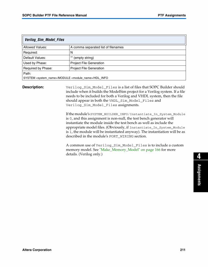
SOPC Builder PTF File Reference Manual PTF Assignments
4
Assignments
Description: Verilog_Sim_Model_Files is a list of files that SOPC Builder should include when it builds the ModelSim project for a Verilog system. If a file needs to be included for both a Verilog and VHDL system, then the file should appear in both the VHDL_Sim_Model_Files and Verilog_Sim_Model_Files assignments.
If the module’s SYSTEM_BUILDER_INFO/Instantiate_In_System_Module is 0, and this assignment is non-null, the test bench generator will instantiate the module inside the test bench as well as include the appropriate model files. (Obviously, if Instantiate_In_System_Module is 1, the module will be instantiated anyway). The instantiation will be as described in the module’s PORT_WIRING section.
A common use of Verilog_Sim_Model_Files is to include a custom memory model. See "Make_Memory_Model" on page 166 for more details. (Verilog only.)
Verilog_Sim_Model_Files
Allowed Values: A comma separated list of filenames
Required: N
Default Values: "" (empty string)
Used by Phase: Project File Generation
Required by Phase: Project File Generation
Path:SYSTEM <system_name>/MODULE <module_name>/HDL_INFO
Altera Corporation 211

PTF Assignments SOPC Builder PTF File Reference Manual
Description: The list of files in this Default Generator parameter will be appended to Verilog_Sim_Model_Files. For more information, please see Verilog_Sim_Model_Files and Synthesis_HDL_Files.
For further information on the Default Generator program, see "CLASS <class_name>/DEFAULT_GENERATOR" on page 64.
verilog_simulation_files
Allowed Values: A comma delimited string of files (relative or absolute path)
Required: N
Default Values: "" (empty string)
Used by Phase: System Bus Generator
Required by Phase: Component Authoring
Path:CLASS <class_name>/DEFAULT_GENERATOR
212 Altera Corporation

SOPC Builder PTF File Reference Manual PTF Assignments
4
Assignments
Description: VHDL_Sim_Model_Files is a list of files that SOPC Builder should include when it builds the ModelSim project for a VHDL system. If a file needs to be included for both a Verilog and VHDL system, then the file should appear in both the VHDL_Sim_Model_Files and Verilog_Sim_Model_Files assignments.
If the module’s SYSTEM_BUILDER_INFO/Instantiate_In_System_Module is 0, and this assignment is non-null, the test bench generator will instantiate the module inside the test bench as well as include the appropriate model files. (Obviously, if Instantiate_In_System_Module is 1, the module will be instantiated anyway). The instantiation will be as described in the module’s PORT_WIRING section.
A common use of VHDL_Sim_Model_Files is to include a custom memory model. See "Make_Memory_Model" on page 166 for more details. (VHDL only.)
VHDL_Sim_Model_Files
Allowed Values: A comma separated list of filenames
Required: N
Default Values: "" (empty string)
Used by Phase: Project File Generation
Required by Phase: Project File Generation
Path:SYSTEM <system_name>/MODULE <module_name>/HDL_INFO
Altera Corporation 213

PTF Assignments SOPC Builder PTF File Reference Manual
Description: The list of files in this Default Generator parameter will be appended to VHDL_Sim_Model_Files. For more information, please see VHDL_Sim_Model_Files and Synthesis_HDL_Files.
For further information on the Default Generator program, see "CLASS <class_name>/DEFAULT_GENERATOR" on page 64.
vhdl_simulation_files
Allowed Values: A comma delimited string of files (relative or absolute path)
Required: N
Default Values: "" (empty string)
Used by Phase: System Bus Generation
Required by Phase: Component Authoring
Path:CLASS<class_name>/MODULE_DEFAULT/HDL_INFO
214 Altera Corporation

SOPC Builder PTF File Reference Manual PTF Assignments
4
Assignments
Description: This assignment is used by the SOPC Builder GUI to decide whether to display the master columns and all of the master-slave connections. It is controlled through the View|Show Master Connections menu and from the right-click (Context) menu. If the assignment is not present, the SOPC Builder GUI will decide whether to display the master columns based on the configuration of the system. For systems with a single CPU (and perhaps a tri-state bus), the GUI will not display the master columns. But if there are more than one CPU, or another master such as DMA, the GUI will default to displaying the master columns. What gets displayed in the master columns is determined by the value of the assignment view_master_priorities. See "view_master_priorities" on page 216 for a description.
view_master_columns
Allowed Values: 01
Required: N
Default Values: 0 for simple systems1 for multi-master systems
Used by Phase: System Configuration
Required by Phase: System Configuration
Path:SYSTEM <system_name>/WIZARD_SCRIPT_ARGUMENTS
Altera Corporation 215

PTF Assignments SOPC Builder PTF File Reference Manual
Description: This assignment is used by the SOPC Builder GUI to decide what to display in the master columns, if view_master_columns=1. It is controlled through the View|Show_Arbitration_Priorities menu and from the right-click (Context) menu.
If view_master_priorities=0, the master columns will be displayed as a patch panel with filled-circles indicating a master-slave connection and empty circles indicating no connection (though connection is possible). Masters and slaves that cannot be connected (e.g., because of incompatible bus-types), are represented as crossing lines with no circles. Clicking on a circle turns on or off the connection between that master and slave. The priority setting used is always 1.
If view_master_priorities=1, the master columns will be displayed with the arbitration values instead of the patch panel. Cells where no connection is possible will be displayed with a hash pattern. Cells where there is no connection, but connection is possible, will be empty. Cells with a connection will have the arbitration value assigned to that connection displayed in the cell. The arbitrations can be edited and assigned any value between 1 and 100. A value of 0 is the same as turning off the connection.
view_master_priorities
Allowed Values: 01
Required: N
Default Values: 0
Used by Phase: System Configuration
Required by Phase: System Configuration
Path:SYSTEM <system_name>/WIZARD_SCRIPT_ARGUMENTS
216 Altera Corporation

SOPC Builder PTF File Reference Manual PTF Assignments
4
Assignments
Description: This assignment defines the width of the port.
In the following example,
SYSTEM my_system { MODULE my_module { PORT my_port { direction = "input"; width = "12"; } } }
The port named my_port has a width of 12. The information in this setting is used to generate appropriately sized vectors to wire up these modules. For VHDL, widths greater than one assume that the type is a STD_LOGIC_VECTOR. With widths of one, assume that the type is STD_LOGIC.
width
Allowed Values: 1 - infinity
Required: Y
Default Values: N/A
Used by Phase: System Bus Generator
Required by Phase: System Bus Generator
Path:SYSTEM <system_name>/MODULE <module_name>/MASTER<master_name>/PORT_WIRING/PORT <port_name>SYSTEM <system_name>/MODULE <module_name>/PORT_WIRING/PORT <port_name>SYSTEM <system_name>/MODULE <module_name>/SLAVE <slave_name>/PORT_WIRING/PORT <port_name>
Altera Corporation 217

PTF Assignments SOPC Builder PTF File Reference Manual
Description: This assignment controls how many wait states the bus inserts between when a master writes and when the data is accepted by the slave. A number indicates the number of wait cycles. The value peripheral_controlled indicates that the slave has a pin of type waitrequest (or waitrequest_n) that will indicate when a write transaction is complete. During the inserted wait states (either peripheral-controlled or predefined), the bus will assert the master’s wait port.
If either of Write_Wait_States or Read_Wait_States is set to peripheral_controlled, both reads and writes will be considered peripheral_controlled.
Write_Wait_State
Allowed Values: 0 – 255peripheral_controlled
Required: N
Default Values: 0
Used by Phase: System Bus Generation
Required by Phase: System Bus Generation
Path:SYSTEM <system_name>/MODULE <module_name>/SLAVE <slave_name>/SYSTEM_BUILDER_INFO
218 Altera Corporation

Altera Corporation
Appendix A
Appendix A5
Calling Conventions for Add/Edit/Bind Programs
The assignments within a component’s class.ptf ASSOCIATED_FILES section are used to reference programs (scripts, etc.) which perform actions associated with the various phases of the SOPC Builder flow (see "SOPC Builder Design Flow" on page 25.
Phase-Related Programs
The phase-related programs covered herein include:
� Add_Program� Edit_Program� Bind_Program
These programs may take one of four forms:
Perl Script
For assignments ending with a .pl extension, an external perl script, specified relative to the component’s class directory, is run. A variation of the Perl language local to the SOPC Builder (based on version 5.6.0 of Perl) is used to execute the script. This script may perform processing silently, invoke a user-interface to gather input, or whatever other tasks it requires.
Java Code
External Java code can be referenced via .jar files or .class files, matching the two common distribution forms.
Java .jar Files
Assignments end in with a .jar extension indicate an external Java ARchive (JAR) is referenced. The name of the JAR file is also used as the name of the class whose main() method will receive command line switches upon invokation.
219

Appendix A SOPC Builder PTF File Reference Manual
Java .class Files
When .class files are referenced, a directory structure mirroring the java class-package structure is expected. The specified .class file will be expected to reside within a directory by the same name (with the .class extension omitted); the package-name is assumed to match the class-name. (In accordance with standard Java package-class notation)
WIZARD_UI Section Reference
Assignments which reference WIZARD_UI sections within a component’s class.ptf section (see "PTF File Sections" on page 63) specify a user-interface layout in PTF file format (rather than an external program, as the above methods specify). The syntax of such layouts are detailed elsewhere.
Invokation
Each form of phase-related program has its own means of being invoked, each with its own initial command line prefix. All forms are passed a common set of SOPC Builder specific command switches.
Type-Specific Command Line Prefixes
Notation assumes $sopc_builder points to SOPC Builder installation root.
Perl
<bin>/perl -I<bin> -I<bin>/europa -I<bin>/perl_lib <script.pl> <common>
<bin> is $sopc_builder/bin
<script.pl> is the phase-related program
<common> are the common switches detailed below
Java
<bin>/<jre>/<java> <classpath> <classname> <common>
<bin> is $sopc_builder/bin
<jre> is jre1.3 currently
<java> is java on Unix, javaw on Windows
220 Altera Corporation

SOPC Builder PTF File Reference Manual Appendix A
Appendix A
5
<classpath> is built-in JAR files and optional Jar_File reference
<classname> is specified by the phase-related program assignment
<common> are the common switches detailed below
WIZARD_UI
User interface layouts defined by WIZARD_UI sections are invoked indifferent ways, depending upon their application.
Add_Program, Edit_Program
When a separate user interface layout is specified, a modal window is used to display its contents. The other windows within SOPC Builder are inoperable until the current user interface is dismissed. You will likely hear a beep and/or see flashing if you try to click on the inoperable windows, so avoid doing so when recording audio through the same sound output device.
Within a WIZARD_UI layout, it is possible to reference Java classes which implement custom functionality. These classes are expected to reside within a .jar file specified by the Jar_File assignment within the ASSOCIATED_FILES section. The Java class search-path have this .jar file’s contents appended to it, for both code and data files.
Bind_Program
Binding programs, which are currently limited to WIZARD_UI-based layouts, are dynamically added and removed from the main SOPC Builder UI as the user edits their system. They share the same environment (command line arguments, etc.) as the SOPC Builder but have their own data-context which is rooted at their associated module’s section. Thus, all modifications performed by binding UIs operate within their associated module by default. Global-system PTF file operations are possible using global contexts such as $SYS.
Common Command Line Switches
All common switches are "double-dash-equals" types, of the form:
--<switch_name>[=<switch_value>]
� --system_directory (all programs)
Path to directory containing system under construction.
Altera Corporation 221

Appendix A SOPC Builder PTF File Reference Manual
� --system_name (all programs)
File name of system under construction.
� --target_module_name (Add/Edit/Generate programs)
Name of the module being added/edited/generated. The section within the system PTF file containing this module is:
– SYSTEM <--system_name>/MODULE <--target_module_name> (where <--switch> refers to the value of the switches above)
� --projectname (Add/Edit programs)
Name of the Quartus project associated with the system under construction.
� --sopc_lib_path (all programs)
A delimited list of directories containing SOPC Builder components, in forward-search order. When resolving a MODULE/class assignment to a CLASS definition section, the class.ptf files inside of all search-path directories' subdirectories (one level deep) are scanned. The first matching class, ranked additionally by the USER_INTERFACE/USER_LABELS/license assignment ("full"=first, "eval"=second, "none"=last) is chosen. The delimiter may be comma (','), plus ('+'), or semi-colon (';').
� --sopc_directory (all programs)
Path to SOPC Builder installation, inscrutably forward-slashed.
� --add (Add program only)
This little switch is passed when an Add_Program is run.
� --edit (Edit program only)
This four-letter switch is passed when an Edit_Program is run.
� --generate (Generate program only)
This exceedingly long switch is passed when a Generate_Program is run.
� --sopc_jar_file (Java Add/Edit programs only)
222 Altera Corporation

SOPC Builder PTF File Reference Manual Appendix A
Appendix A
5
Specifies path to .jar file containing classes referenced by WIZARD_UI descriptions.
Altera Corporation 223

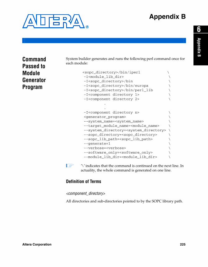
Altera Corporation
A
6
Appendix B
ppendix BCommand Passed to Module Generator Program
System builder generates and runs the following perl command once for each module:
<sopc_directory>/bin/iperl \ -I<module_lib_dir> \ -I<sopc_directory>/bin \ -I<sopc_directory>/bin/europa \ -I<sopc_directory>/bin/perl_lib \ -I<component directory 1> \ -I<component directory 2> \ . . -I<component directory n> \ <generator_program> \ --system_name=<system_name> \ --target_module_name=<module_name> \ --system_directory=<system_directory> \ --sopc_directory=<sopc_directory> \ --sopc_lib_path=<sopc_lib_path> \ --generate=1 \ --verbose=<verbose> \ --software_only=<software_only> \ --module_lib_dir=<module_lib_dir> \
1 ’\’ indicates that the command is continued on the next line. In actuality, the whole command is generated on one line.
Definition of Terms
<component_directory>
All directories and sub-directories pointed to by the SOPC library path.
225

Appendix B SOPC Builder PTF File Reference Manual
<generator_program>
The perl script which is run to generate the module. This program is specified by the class.ptf file for the component. If the system generator script has been called with --software_only_mode = 1, then the program which will be run is specified by the class.ptf/Software_Rebuild_Program setting. If no Software_Rebuild_Program is set, no generator program will be called for this component.
If the system generator is called with --software_only mode = 0, then the program which will be run is specified by the class.ptf/ Generator_Program setting. If no generator program is specified, the default_generator program is run. If the CLASS generator_ program is assigned to --NONE--, no generator program will be called for this component.
<module_lib_dir>
The directory which contains the class.ptf file.
<module_name>
The name of the module in system builder that is being generated. See the following PTF system file example:
SYSTEM my_system { MODULE first_module { class = altera_avalon_usb; } ... }
The call to generate first_module, would set --target_module_name= first_module
<software_only>
Reflects the value of the --software_only flag which was passed to system builder.
<sopc_directory>
The directory where sopc_builder is installed.
226 Altera Corporation

SOPC Builder PTF File Reference Manual Appendix B
Appendix B
6
<sopc_lib_path>The full path to all component libraries.
<system_directory>
The name of the directory which contains the system PTF file.
<system_name>
The name of the system PTF file and of the system name at the top level. Thus, the system PTF file is located at <system_directory>/<system_name>.ptf. It contains at its top level
SYSTEM <system_name>{}
<verbose>
Set to 1 for verbosity. Generator programs may do what they wish with this flag.
Altera Corporation 227

Altera Corporation
O
1
Appendix C
verviewPTF Syntax: Formal BNF
This section defines the syntax of a PTF file rigorously using Backus-Naur form (BNF). See "PTF Syntax Described" on page 37 for an explanation of each element.
The syntax presented here is the narrowest definition of the PTF format. Some parsers are “loose” and accept PTF-file format which does not fit this syntax. PTF file authors are advised to rigidly follow this syntax instead of relying on the behavior of any particular parser.
In the syntax notation used in this section, we surround literal words and characters by ‘single quotes’, and we leave non-terminals unquoted. We indicate repetition of language elements using suffixes. An asterisk * indicates zero or more occurrences, a plus + indicates one or more occurrences, and a question mark ? indicates zero or one occurrence. We use the “or” bar | to indicate alternatives and parentheses ( ) for grouping.
Example: comma-separated list of elements:
list ::= element ( ‘,’ element )*
Lexical Elements
Characters of a PTF file are grouped lexically into tokens before further syntactic processing. Tokens are identifiers, string literals, numbers, punctuators, and hierarchical names.
token ::= identifier | string_literal | number | punctuator | hierarchical_name
Tokens can be separated by white space, which includes comments and/or white-space characters (space, horizontal tab, and new-line). White space may appear within a token only as part of a string literal or a hierarchical name.
Comments
Except within a string literal, any occurrence of ‘#’ starts a comment. The comment extends to the end of the line. As mentioned, comments are treated as white space.
229
Appendix C SOPC Builder PTF File Reference Manual
comment ::= ‘#’ comment_char* comment_char ::= any character except new-line
Identifiers
An identifier is a sequence of letters, digits, underscores, and slashes. Identifiers must start with a letter or an underscore.
identifier ::= ( letter | ‘_’ ) ( letter | digit | ‘_’ | ‘/’ )* letter ::= ‘a’..’z’ | ‘A’..’Z’ digit ::= ‘0’..’9’
Numbers
A number is a sequence of digits.
number ::= digit+
String Literals
A string literal is a sequence of zero or more characters separated by double-quote characters. Use the escape sequence \" to include a double-quote character" within a string literal. Use the escape sequence \\ to include a backslash \ within a string literal. Use \n for the end-of-line character. String literals may span multiple lines.
string_literal ::= ‘"’ s_char* ‘"’
s_char ::= escape_sequence | any character except double-quote" or backslash \
escape_sequence ::= ‘\"’ | ‘\\’ | ‘\n’
A statement may be embedded in a string literal by enclosing it within doubled braces {{ }}. The text between the doubled braces may contain unescaped double quotes ".
Punctuators
A punctuator is one of the punctuation tokens used in a PTF file.
punctuator ::= ‘=’ | ‘;’ | ‘{’ | ‘}’
230 Altera Corporation

SOPC Builder PTF File Reference Manual Appendix C
Overview
1
Hierarchical NamesA hierarchical name is a sequence of characters starting with one or two dollar signs $ and containing letters, digits, underscores, slashes, and spaces. Although a hierarchical name can contain embedded spaces, trailing spaces are not part of the hierarchical name.
hierarchical_name ::= ‘$’ ‘$’? (letter | digit | ‘ ’| ‘/’ | ‘_’ )+
Syntactic Elements
Tokens of a PTF-file document are organized into nested sections, as defined by the BNF rules below.
document ::= section+
section ::= section_type section_name? ‘{’ section_element* ‘}’ section_type ::= identifier section_name ::= identifier | number | string_literal section_element ::= assignment | section
assignment ::= assignment_name ‘=’ assignment_value ‘;’ assignment_name ::= identifier | hierarchicial_name assignment_value ::= string_literal | number
Altera Corporation 231

Appendix C SOPC Builder PTF File Reference Manual
232 Altera Corporation