SOP 6-1 Sonde Calibration and Maintenance · Title: Sonde Calibration and Maintenance Effective...
47
Title: Sonde Calibration and Maintenance Effective Date: 1/22/2018 New Mexico Environment Department Surface Water Quality Bureau Standard Operating Procedure for SONDE CALIBRATION AND MAINTENANCE Approval Signatures Mater Expert, SWQB istopher Barrios Program Manager, Monitoring Assessment and Standards Section, SWQB 1.0 Purpose and Scope I No: SOP-6.1 I Page 1 of 47 I I Revision 4 -1 I Next Revision Date: 3/01/2020 Date Date t!tt:fktJ/8 I' Date The purpose of this standard operating procedure (SOP) is to describe the procedure for calibrating and maintaining water quality monitoring sondes and dataloggers for collection of instantaneous or unattended measurements. This procedure covers the use of the YSI 6-series sonde, Hydrolab MSS sonde, In-Situ Aqua TROLL 600 sonde, and Onset HOBO ® dissolved oxygen (DO) datalogger and conductivity datalogger. 2.0 Responsibilities Bureau personnel who deploy water quality monitoring sondes and dataloggers are responsible for ensuring that the sondes are properly calibrated, checked and maintained, and that the data are properly recorded in accordance with this SOP and shall acknowledge such by signing the SOP 6.1 Sonde Calibration and Maintenance Acknowledgment Page. In addition to personnel who use sondes and data loggers, one individual within SWQB is designated as the "Sonde Manager." A second individual is designated as the "Alternate Sonde Manager" who fulfills the manager's responsibilities when the manager is unavailable. The Sonde Manager or Alternate Sonde Manager is responsible for: • ensuring sondes are properly maintained and stored;
Transcript of SOP 6-1 Sonde Calibration and Maintenance · Title: Sonde Calibration and Maintenance Effective...

Title: Sonde Calibration and Maintenance
Effective Date: 1/22/2018
New Mexico Environment Department Surface Water Quality Bureau
Standard Operating Procedure
for
SONDE CALIBRATION AND MAINTENANCE
Approval Signatures
~ ~--=== Su~bject Mater Expert, SWQB
istopher Barrios Program Manager, Monitoring Assessment and Standards Section, SWQB
1.0 Purpose and Scope
I No: SOP-6.1 I Page 1 of 47 I I Revision 4 -1 I Next Revision Date: 3/01/2020
Date
Date
t!tt:fktJ/8 I'
Date
The purpose of this standard operating procedure (SOP) is to describe the procedure for calibrating and maintaining water quality monitoring sondes and dataloggers for collection of instantaneous or unattended measurements. This procedure covers the use of the YSI 6-series sonde, Hydrolab MSS sonde, In-Situ Aqua TROLL 600 sonde, and Onset HOBO ® dissolved oxygen (DO) datalogger and conductivity datalogger.
2.0 Responsibilities
Bureau personnel who deploy water quality monitoring sondes and dataloggers are responsible for ensuring that the sondes are properly calibrated, checked and maintained, and that the data are properly recorded in accordance with this SOP and shall acknowledge such by signing the SOP 6.1 Sonde Calibration and Maintenance Acknowledgment Page.
In addition to personnel who use sondes and data loggers, one individual within SWQB is designated as the "Sonde Manager." A second individual is designated as the "Alternate Sonde Manager" who fulfills the manager's responsibilities when the manager is unavailable. The Sonde Manager or Alternate Sonde Manager is responsible for:
• ensuring sondes are properly maintained and stored;

Title: Sonde Calibration and Maintenance No: SOP-6.1 j--P~ge 2 of 47 I 1--::=-::o---,-,--=-,---:-=-=-=-=:-:-=---------------!-R;-;--:-evision 4 j
Effective Date: 1/22/2018 Next Revision Date: 3/01/2020 J
• maintaining the "Sonde Tracker" spreadsheet; • maintaining electronic data files on NMED's internal server under "MASS"; • maintaining calibration sheets in binders stored in the laboratory in order to avoid
confusion and/or misplacement of data; and, • training field personnel, as needed, so they are capable of operating sondes, including
calibration, post-deployment checking, and data recording
Field Staff are responsible for: • coordinating with the Sonde Manager or Alternate Sonde Manager on the scope of the
project and use of the equipment; • investigating calibration and calibration verification failures and reporting equipment
malfunction to the Sonde Manager or Alternate Sonde Manager. • transferring sonde data off the instrument following long-term deployment in accordance
with SWQB's Data Logger and Upload SOP (SOP 6.4); • ensuring equipment is cleaned and stored in accordance with this SOP; • quality assurance (QA) ofsonde/datalogger data in accordance with the SWQB's Data
Verification and Validation SOP (SOP 15.0); and, • filing calibration sheets in binders stored in the laboratory and filing
deployment/calibration/post check sheets and sampling run post-checks in the project binder.
3.0 Background and Precautions
3.1 Background This procedure is based on the capabilities of the In-Situ, YSI, and Hydro lab sondes and sensors and Onset HOBO® Dissolved Oxygen (DO) dataloggers and Onset HOBO® Conductivity dataloggers described in Section 5.0.
3.2 Procedural Precautions Individuals using a sonde or datalogger should have a thorough understanding of its proper use and care and be familiar with the instrument's operational manual in order to ensure data is not invalidated due to calibration or user error.
3.3 Safety Precautions While the cleaning and calibration solutions used for maintenance of these instruments are generally non-hazardous, operators must have a signature for the Chemical Hazard Plan (CHP) on file and be familiar with applicable Safety Data Sheets (SDS). Operators must also have a signature for the Sampling Job Hazard Analysis on file and be aware of hazards that might be present, develop, and/or are unique to the station.
4.0 Definitions
Program Manager- An individual within the SWQB that manages a program such as the Watershed Protection Section (WPS), the Point Source Regulation Section (PSRS) or the

Title: Sonde Calibration and Maintenance No: SOP-6.1 _I Page 3 of 47 Revision 4 I
Effective Date: 1/22/2018 Next Revision Date: 3/01/2020
Monitoring, Assessment and Standards Section (MASS). The Program Manager and Project Manager are not necessarily synonymous.
Project Manager- An individual responsible for a specific project. This individual, in most cases, holds a different title within the organization. The Program Manager and Project Manager are not necessarily synonymous. The Project Manager may be the same individual as the Subject Matter Expert.
Quality Assurance Officer (QAO)- Is the individual within the MASS that is responsible for overseeing the development and implementation of all quality assurance procedures and processes within the SWQB including those projects that receive support or funding from the SWQB. The QAO is also responsible for validating and verifying data sets for potential use in assessment of surface waters.
Quality Assurance Project Plan (QAPP)- A formal planning document for environmental data collection activities that describes the data collection procedures and the necessary quality assurance and quality control activities that must be implemented to ensure that the results are sufficient and adequate to satisfy the stated performance criteria.
Quality Management Plan (QMP) -establishes the principles, requirements, and practices necessary to implement the quality system for the SWQB's environmental data operations.
Standard Operating Procedure (SOP)- A document that lists the steps that should be completed when doing a task.
Subject Matter Expert (SME)- A person who is familiar with the purpose and procedure for accomplishing a task. The SME may be the same individual as the Project Manager.
Surface Water Quality Bureau (SWQB)- A Bureau under the Water Protection Division of the New Mexico Environment Department. The SWQB's mission is to preserve, protect, and improve New Mexico's surface water quality for present and future generations.
Sonde - A water quality monitoring device that is placed in the water to gather water quality data. Sondes usually have multiple sensors and are capable of recording or displaying multiple water quality parameters.
Dissolved Oxygen (DO) logger- A water quality monitoring device that measures and records dissolved oxygen concentration and saturation and temperature.
Conductivity logger- A water quality monitoring device that measures and records conductivity and temperature.
Title: Sonde Calibration and Maintenance I No: ~~P-6.1 I Page 4 of 47 I _j r ReVISIOn 4 -
1--------------------------------------~ I Next Revision Date: 3/01/2020 Effective Date: 1/22/2018 I
I
5.0 Equipment and Tools
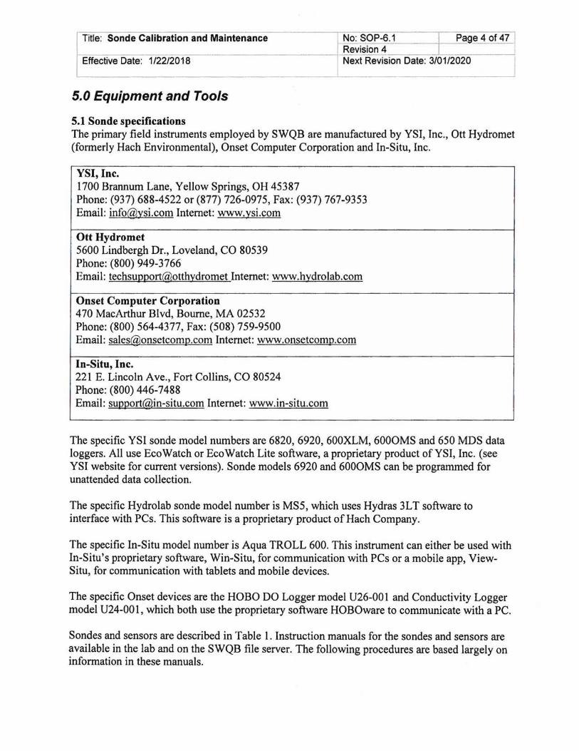
5.1 Sonde specifications The primary field instruments employed by SWQB are manufactured by YSI, Inc., Ott Hydromet (formerly Hach Environmental), Onset Computer Corporation and In-Situ, Inc.
YSI, Inc. 1700 Brannum Lane, Yellow Springs, OH 45387 Phone: (937) 688-4522 or (877) 726-0975, Fax: (937) 767-9353 Email: info@~si.com Internet: www.~si.com
Ott Hydromet 5600 Lindbergh Dr. , Loveland, CO 80539 Phone: (800) 949-3766 Email: techsuggort@otth~dromet Internet: www.h~drolab.com
Onset Computer Corporation 470 MacArthur Blvd, Bourne, MA 02532 Phone: (800) 564-4377, Fax: (508) 759-9500 Email: [email protected] Internet: www.onsetcomg.com
In-Situ, Inc. 221 E. Lincoln Ave., Fort Collins, CO 80524 Phone: (800) 446-7488 Email: [email protected] Internet: www.in-situ.com
The specific YSI sonde model numbers are 6820, 6920, 600XLM, 6000MS and 650 MDS data loggers. All use EcoWatch or EcoWatch Lite software, a proprietary product ofYSI, Inc. (see YSI website for current versions). Sonde models 6920 and 6000MS can be programmed for unattended data collection.
The specific Hydrolab sonde model number is MS5, which uses Hydras 3LT software to interface with PCs. This software is a proprietary product ofHach Company.
The specific In-Situ model number is Aqua TROLL 600. This instrument can either be used with In-Situ's proprietary software, Win-Situ, for communication with PCs or a mobile app, ViewSitu, for communication with tablets and mobile devices.
The specific Onset devices are the HOBO DO Logger model U26-001 and Conductivity Logger model U24-001, which both use the proprietary software HOBOware to communicate with a PC.
Sondes and sensors are described in Table 1. Instruction manuals for the sondes and sensors are available in the lab and on the SWQB file server. The following procedures are based largely on information in these manuals.

Title: Sonde Calibration and Maintenance I No: SOP-6.1 I Page 5 of47 I I Revision 4 I
Effective Date: 1/22/2018 j Next Revision Date: 3/01/2020
Table 1
Sonde and Sensor Characteristics
Sensor Parameter Units Range Accuracy
YSI 6560 Temperature oc -5 to +50 ± 0.15 oc 6560 Conductivity J.LS/cm 0- ± 0.5% of reading;± 1
100,000 l:!S/cm 6562 Dissolved % 0-500 ±2%
Ox~gen saturation 6150 (Optical) Dissolved % 0-500 ± 1%
Ox~gen saturation 6562 Dissolved mg/L 0-50 0 to 20 mg/L: ± 0.1 mg/L
Oxygen or 1% of reading, whichever is greater; 20 to 50 mg/L: ± 15% of read in
6150 (Optical) Dissolved mg/L 0-50 0 to 20 mg/L: ± 0.2 mg/L Oxygen or 2% of reading,
whichever is greater; 20 to 50 mg/L: ±6% of read in
6561 pH su 0-14 ± 0.2 su 6026 or 6136 Turbidity NTU 0-1000 ±2%
Hydro lab
MS5 Thermistor Temperature oc -5 to +50 ± 0.10 oc 004468 Conductivity !J.S/cm 0- ± 1% of reading; ± 1
100,000 l:!S/cm 007455 Dissolved % 0-500 ± 1%
Ox~gen saturation 007455 Dissolved mg/L 0-60 ± 0.1 mg/L for 0-8 mg/L;
Oxygen ± 0.2 mg/L for greater than 8 mg/L
004446 pH su 0-14 ± 0.2 su 007140 Turbidity NTU 0-3000 ± 1% up to 100 NTU, ±
3% up to 100-400 NTU, ± 5% from 400-3000 NTU
Onset DO Logger
U26-001 Dissolved mg/L 0-30 0.2mg/L up to 8mg/L; 0.5 Ox~gen mg/L from 8 to 20mg/L

Title: Sonde Calibration and Maintenance
Effective Date: 1/22/2018
Thermistor Temperature
Onset Conductivity Logger
U24-00 1 Conductivity
Thermistor
In-Situ 63490
63490
63450
63450
63470
63480
Temperature
Temperature
Conductivity
Dissolved Oxygen Dissolved Oxygen
pH
Turbidity
J.!Sicm
% saturation mg/L
su NTU
No: SOP-6.1 ~~ge 6 of 47 I Revision 4 I Next Revision Date: 3/01/2020
-5 to 40
0- 10,000 ± 3% of reading; ± 5 S/cm
5-35 ± 0.1 oc
-5 to +50
0-200,000
0-500
0-50
0-14
0-4000
± 0.5% of reading;± 1 flS/cm for 0-1 00,000, ± 1% of reading > 100,000 ± 1%
± 0.1 mg/L for 0- 8 mg/L; ± 0.2 mg/L for greater than 8 mg/L ± 0.1 su ± 2% of reading; ± 2 NTU
5.2 List of equipment required for sonde calibration and maintenance
Calibration forms Calibration solutions*
Deionized water pH buffer solutions Turbidity standards Specific conductance standard
Barometer Abrasion-free cleaning cloth (Kim wipes) Compressed air Sonde stand Solution disposal bucket five (5) gallons YSI Sonde
Sonde with appropriate sensors 650Handset Communication cable Transport cover/cup Probe guard DO membranes DO 0-rings DO electrolyte Replacement wiper pads Hex key set
Hydrolab Sonde Sonde with appropriate sensors
Title: Sonde Calibration and Maintenance I No: SOP-6.1 I Page 7 of 47 I Revision 4 I
Effective Date: 1/22/2018 I Next Revision Date: 3/01/2020
~---------------------------------------~------------------------~
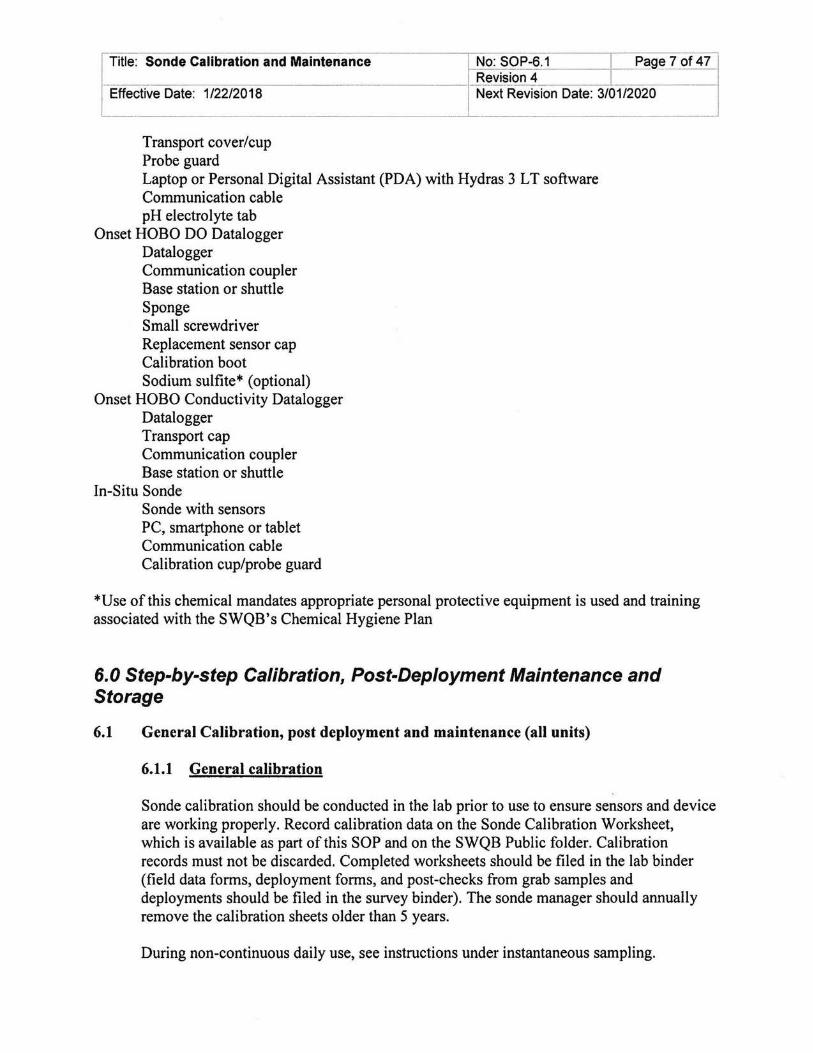
Transport cover/cup Probe guard Laptop or Personal Digital Assistant (PDA) with Hydras 3 L T software Communication cable pH electrolyte tab
Onset HOBO DO Datalogger Datalogger Communication coupler Base station or shuttle Sponge Small screwdriver Replacement sensor cap Calibration boot Sodium sulfite* (optional)
Onset HOBO Conductivity Datalogger Datalogger Transport cap Communication coupler Base station or shuttle
In-Situ Sonde Sonde with sensors PC, smartphone or tablet Communication cable Calibration cup/probe guard
*Use of this chemical mandates appropriate personal protective equipment is used and training associated with the SWQB's Chemical Hygiene Plan
6.0 Step-by-step Calibration, Post-Deployment Maintenance and Storage
6.1 General Calibration, post deployment and maintenance (all units)
6.1.1 General calibration
Sonde calibration should be conducted in the lab prior to use to ensure sensors and device are working properly. Record calibration data on the Sonde Calibration Worksheet, which is available as part of this SOP and on the SWQB Public folder. Calibration records must not be discarded. Completed worksheets should be filed in the lab binder (field data forms, deployment forms, and post-checks from grab samples and deployments should be filed in the survey binder). The sonde manager should annually remove the calibration sheets older than 5 years.
During non-continuous daily use, see instructions under instantaneous sampling.
I No: SOP-6.1 Page 8 of 471 Revision 4 ~
Title: Sonde Calibration and Maintenance
j Next Revision Date: 3/01/2020 1 !
Effective Date: 1/22/2018 L_ ______________________________________ _L __________________________ ~
Between unattended sonde deployments and prior to redeployment, clean sensors if necessary and recalibrate. Replace the DO membrane (rapid pulse sensors only).
After extended storage periods or upon retrieval from deployment (following postcheck), clean the cup, guard, sonde and the sensors. Follow the unit-specific instructions for sensor maintenance and cleaning procedures.
To prepare the sonde for calibration, rinse all sensors and the entire inside of the calibration cup once with DI or tap water. This can be done with a squirt bottle, faucet, or by adding water to the cup and swirling or inverting so that the water comes in contact with all areas of the sonde sensors and cup. Next, rinse twice with the calibration standard by adding standard into the cup, installing the cup to the sonde, and swirling or inverting so the standard makes contact with all areas of the sonde sensors and cup before discarding. Be certain to avoid cross-contamination of standard solution with other solutions.
Complete a post-check in the lab after deployments and single point grab data collections. Fill out the bottom half of the Sonde Calibration form under "validation." If a sonde was taken into the field and not used, write "Not Used" on the bottom half of the Sonde Calibration form.
6.1.1.1 General information regarding Dissolved Oxygen
Upon arriving at the sampling location, DO should be field calibrated to local elevation to ensure accurate measurements. Record DO field calibration data on the site-specific Field Data Form or on the Deployment Form/Calibration Worksheet. When collecting grab samples, changes in elevation greater than 1 ,000' (300m) require a recalibration.
For rapid pulse DO sensors, after changing the membrane, follow procedures outlined in the calibration tips (YSI, 201 0).
6.1.1.2 General information regarding Specific Conductance
Conductivity standards are very sensitive to contamination. Inscribe the date on the standard container when opening. Standards in bottles that are exposed to air expire one month after opening. Bulk standard in Cubitainers with a tap that does not get exposed to air will be considered expired after 6 months. Standard transferred from a bulk container to a smaller container needs the date of transfer on the smaller container and expires after one month. Expired standard can be used as a rinse before calibration with a non-expired standard.
6.1.1.3 General information on pH Sensors
Calibrate the pH sensor with buffers of pH 7.0, and either pH 4.0 for acidic waters or pH 10.0 for alkaline waters. If the expected pH of the water being sampled is

Title: Sonde Calibration and Maintenance I No: SOP-6.1 I Page 9 of 47 Revision 4 I
Effective Date: 1/22/2018 J Next Revision Date: 3/01/2020 I
unknown, then a 3-Point calibration should be performed following the pH 7, 4, then 1 0 pattern. The pH buffers contain high concentrations of phosphate. Take care during calibration to avoid leaving traces of buffer on equipment or at the work place that could contaminate water samples. Inscribe the date the container is opened on the label. Label buffer solutions prepared from reagent powder or concentrate with date of preparation. (Bulk standard in Cubitainers with a tap that does not get exposed to air will be considered expired on the date stated on the container. Standard transferred from a bulk container to a smaller container needs the date of transfer on the smaller container and expires after six months. Expired standard can be used as a rinse before calibration with a non-expired standard.)
6.1.1.4 General information on Turbidity Sensors
Inscribe the date the turbidity standard container is opened on the label. Standard is expired after 6 months from opening or by the date listed on the container if less than 6 months from opening. Expired standard can be used as a rinse before calibration with a non-expired standard.
Prior to using any turbidity standard gently swirl the standard for approximately 30 seconds to re-suspend the formazin or polymers. Failure to do so will bias calibration high and future calibrations low using that standard container.
6.1.1.5 General information on Temperature Sensor
YSI, In-Situ, Onset and Hydrolab thermistors cannot be calibrated. Annually, or when a malfunction is suspected, check the temperature reading against a NIST traceable thermometer to ensure suitable instrument performance, ±0.5 °C (see Table 2).
6.1.1.6 Two Point versus Three Point Calibration
For pH and Turbidity, a three point calibration should be used to bracket ambient water quality if a two point calibration is not sufficient or if the range of values is unknown or expected to vary greatly. Typically, a two-point calibration is sufficient for grab samples while a three-point calibration is recommended for long-term deployments.
6.1.1.7 Calibration Range
In-calibration range limits are shown in Table 2. If sensors cannot be calibrated within these limits, the instrument should be returned to the sonde manager or alternate sonde manager for maintenance.
6.1.2 General Post Check

Title: Sonde Calibration and Maintenance
Post checks will be conducted following grab data collections during sampling runs and after long term deployments. Post checks are conducted by viewing the sonde's live readings in a calibration standard or in 100% saturated air or water for DO. Do not clean the sonde prior to conducting the post check.
For DO it is recommended to complete post checks in the field at the last site of a sampling run or at retrieval from a long-term deployment site. If performing the DO saturation post check off site at a difference elevation, use the USGS Dissolved Oxygen Tables (https://water.usgs.gov/software/DOTABLES/ or available from the sonde manager or alternate sonde manager) to calculate percent saturation from concentration. Follow the sonde and sensor specific calibration instructions to get 100% saturation of air or water. Tum on the sonde and view live readings, allow to stabilize, and record the live reading of% saturation, mg/L, temperature, and pressure (mmHg) on the deployment sheet or calibration form.
Post checks for the other sensors can be done in the field or in the lab. Take care to not wash debris or biofouling from the sonde during post check. Gently rinse all sensors and the entire inside of calibration cup once with DI or tap water. This can be done with a squirt bottle, faucet, or by adding water to the cup and swirling or inverting so that the water comes in contact with all areas of the sonde sensors and cup. Next, rinse twice with the calibration standard by adding standard into the cup, installing the cup to the sonde, and swirling or inverting so the standard makes contact with all areas of the sonde sensors and cup before discarding. Be certain to avoid cross-contamination of standard solution with other solutions. Fill the cup/restrictor/beaker with fresh standard and allow to stabilize. Record the required sensor readings in the post check section of the sonde calibration form and apply the correct qualifier code if it is out ofrange (see Table 2).
pH post checks are required for pH 7 and 10 for all grab data and deployments. If pH values of less than 7 were observed then a post check of pH 4 must be conducted.
Turbidity post checks for grab data will only be post checked for 0 NTU with DI water. Lower end values during grab collections are used to confirm the 30 NTU threshold used to determine total recoverable AL filtration requirements. Grab turbidity data are not used for assessment. Turbidity post checks for a deployed sonde are conducted with 0, 100/126 and 1000 NTU standards. If the data have been reviewed prior to the post check and no values over 100/126 were observed then it is not necessary to conduct 1000 NTU post check.
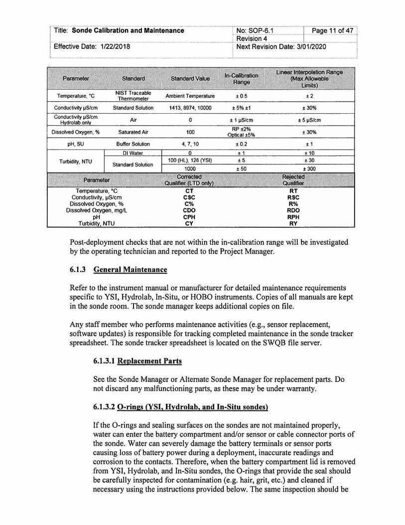
Table 2. In-Calibration and Interpolation Ranges for Sonde Calibration
Title: Sonde Calibration and Maintenance
Effective Date: 1/22/2018
Temperature, •c
Conductivity IJS/cm Standard Solution
Air
Dissolved Oxygen, % Saturated Air
pH, SU Buffer Solution
01 Water
Turbidity, NTU Standard Solution
Temperature, oc Conductivity, ~Stem
Dissolved Oxygen, % Dissolved Oxygen, mg/L
pH Turbidi NTU
Ambient Temperature
1413, 8974, 10000
0
100
4, 7, 10
0 100 (HL), 126 (YSI)
1000
Corrected Qualifier (L TO on
CT esc C% coo CPH CY
No: SOP-6.1 I Page 11 of 47 Revision 4 I -Next Revision Date: 3/01/2020
ln-CaHbration Range
±0.5
±5%±1
± 11JS/cm
RP±2% 0 tical±5%
±0.2
± 1 ±5
±50
Linear Interpolation Range (Max Allowable
Limits)
±2
±30%
± 51JS/cm
R% ROO RPH RY
± 3QOA,
± 1
Post-deployment checks that are not within the in-calibration range will be investigated by the operating technician and reported to the Project Manager.
6.1.3 General Maintenance
Refer to the instrument manual or manufacturer for detailed maintenance requirements specific to YSI, Hydro lab, In-Situ, or HOBO instruments. Copies of all manuals are kept in the sonde room. The sonde manager keeps additional copies on file.
Any staff member who performs maintenance activities (e.g., sensor replacement, software updates) is responsible for tracking completed maintenance in the sonde tracker spreadsheet. The sonde tracker spreadsheet is located on the SWQB file server.
6.1.3.1 Replacement Parts
See the Sonde Manager or Alternate Sonde Manager for replacement parts. Do not discard any malfunctioning parts, as these may be under warranty.
6.1.3.2 0-rings (YSI, Hydrolab, and In-Situ sondes)
If the 0-rings and sealing surfaces on the sondes are not maintained properly, water can enter the battery compartment and/or sensor or cable connector ports of the sonde. Water can severely damage the battery terminals or sensor ports causing loss of battery power during a deployment, inaccurate readings and corrosion to the contacts. Therefore, when the battery compartment lid is removed from YSI, Hydrolab, and In-Situ sondes, the 0-rings that provide the seal should be carefully inspected for contamination (e.g. hair, grit, etc.) and cleaned if necessary using the instructions provided below. The same inspection should be
Title: Sonde Calibration and Maintenance
Effective Date: 1/22/2018
No: SOP-6.1 ___ Lfage 12 of4~ Revision 4 C j
__ j,__.Next Revision Date: 3/01/20~
made of the 0-rings associated with sensors, port plugs and field cable connectors when they are removed. If no dirt or damage to the 0-rings is evident, they should be lightly greased (see below) without removal from their groove. However, if there is any indication at all of damage, the 0-ring should be replaced with an identical item from the YSI 6570 Maintenance Kit or Hydrolab Maintenance Kit supplied with the sondes. At the time of 0-ring replacement, the entire 0-ring assembly should be cleaned as described below. See the manufacturer's instrument manual for details regarding 0-ring removal and installation.
CAUTION: Do not use alcohol on 0-rings as this may cause a loss of elasticity and promote cracking. Do not use a sharp object to remove the 0-rings. Damage to the 0-ring or the groove itself may result. Before re-installing the 0-rings, make sure that you are using a clean workspace, clean hands, and are avoiding contact with anything that may leave fibers on the 0-ring or grooves. Even a very small bit of contamination (hair, grit, etc.) may cause a leak.
Do not over-grease the 0-rings. The excess grease may collect grit particles that can compromise the seal. Excess grease can also cause the waterproofing capabilities of the 0-ring to diminish, potentially causing leaks into the compartment. If excess grease is present, remove it using lens cloth or lint-free cloth.
6.1.3.3 Sonde Sensor Ports
Whenever you install, remove, or replace a sensor or port plug, it is extremely important that the entire sonde and all sensors and plugs be thoroughly dried prior to removal of the sensor or sensor port plug. This will prevent water from entering the port. Following removal of sensor or plug, examine the connector inside the sonde sensor port. If any moisture is present, rinse both the port and the sensor with DI water, remove the water with three rinses of 95% ethanol and dry thoroughly with compressed air. Equipment subjected to this procedure must air dry for at least 24 hours before re-assembly. If the connector is corroded, return the sonde to the Sonde Manager or Alternate. When reinstalling a sensor or port plug, lightly grease the 0-ring with lubricant supplied in the Maintenance Kit or food-grade silicone grease.
6.1.3.4 Cable Connector Port
The cable connector port at the top of the sonde should be covered at all times. When a communications cable is not connected to the cable connector port, the pressure cap supplied with the instrument should be securely tightened in place. If moisture has entered the connector port, dry it completely using 95% ethanol and compressed air. Never attempt to dry the connector port with a rag or paper towel as this may bend the pins. Apply a very thin coat of lubricant from the Maintenance Kit or food-grade silicone grease to the 0-ring inside the connector cap periodically throughout the year.

Title: Sonde Calibration and Maintenance
Effective Date: 1/22/2018
Symptoms
DO reading unstable or inaccurate
pH, ORP, readings are unstable or inaccurate. Error messages appear during calibration.
Conductivity unstable or inaccurate. Error messages appear during calibration.
rou es oo m2 Table 3
T bl h f Possible Cause
Sensor not properly calibrated Membrane not properly installed DO sensor electrodes require cleaning
Water in sensor connector Algae or other contaminant clinging to DO sensor Calibrated using improper barometric pressure
Calibrated at extreme temperature
DO Charge too high (>75) 1. Anodes polarized (tarnished) 2. Moisture in sensor port 3. Sensor has internal short.
DO Charge too low ( <25) 1. Insufficient or diluted electrolyte (membrane may be compromised). 2. DO sensor has been damaged 3. Internal failure Sensor requires cleaning, Sensor requires calibration pH sensor has dried out from improper storage. Water in sensor connector Sensor has been damaged Calibration solutions out of spec or contaminated with other solution Internal failure Conductivity improperly_ calibrated. Conductivity sensor contains bubbles or requires cleaning Conductivity sensor damaged Calibration solution out of spec or contaminated Internal failure
No: SOP-6.1 -~ge 13 of47 Revision 4 Next Revision Date: 3/01/2020
Action Follow DO calibration procedures Follow 6562 setup procedure
Follow DO cleaning procedure. Use 6035 maintenance kit Dry connector; reinstall sensor
Rinse DO sensor with clean water
Repeat DO calibration procedure using proper barometric pressure Recalibrate at (or near) sample temperature Recondition sensor with 6035 Maintenance Kit. Follow DO cleaning procedure. Dry carefully using instructions above. Replace sensor. Return defective sensor to sonde manager.
Replace electrolyte and membrane. Replace 6562 sensor Return sonde for service Follow sensor cleaning procedure Follow calibration procedures Soak sensor in tap water or buffer until readings become stable Dry connector; reinstall sensor Replace sensor
Use new calibration solutions Return sonde for service Follow calibration procedure Flush bubbles or follow cleaning procedure Replace sensor
Use new calibration solution Return sonde for service
Title: Sonde Calibration and Maintenance No: SOP-6.1 I Page 14 of 47 I Revision 4 I
Effective Date: 1/22/2018 Next Revision Date: 3/01/2020
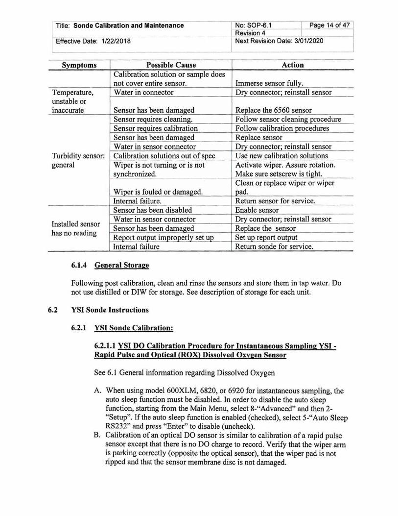
Sym()_toms Possible Cause Action Calibration solution or sample does not cover entire sensor. Immerse sensor fully.
Temperature, Water in connector Dry connector; reinstall sensor unstable or inaccurate Sensor has been damaged Replace the 6560 sensor
Sensor requires cleaning. Follow sensor cleaning procedure Sensor requires calibration Follow calibration procedures Sensor has been damaged Replace sensor Water in sensor connector Dry connector; reinstall sensor
Turbidity sensor: Calibration solutions out of spec Use new calibration solutions general Wiper is not turning or is not Activate wiper. Assure rotation.
synchronized. Make sure setscrew is tight. Clean or replace wiper or wiper
Wiper is fouled or damaged. pad. Internal failure. Return sensor for service. Sensor has been disabled Enable sensor
Installed sensor Water in sensor connector Dry connector; reinstall sensor Sensor has been damaged Replacethe sensor
has no reading Report output improperly set up Set up reJ>ort out~>_ut Internal failure Return sonde for service.
6.1.4 General Storage
Following post calibration, clean and rinse the sensors and store them in tap water. Do not use distilled or DIW for storage. See description of storage for each unit.
6.2 YSI Sonde Instructions
6.2.1 YSI Sonde Calibration:
6.2.1.1 YSI DO Calibration Procedure for Instantaneous Sampling YSI -Rapid Pulse and Optical (ROX) Dissolved Oxygen Sensor
See 6.1 General information regarding Dissolved Oxygen
A. When using model 600XLM, 6820, or 6920 for instantaneous sampling, the auto sleep function must be disabled. In order to disable the auto sleep function, starting from the Main Menu, select 8-"Advanced" and then 2-"Setup". If the auto sleep function is enabled (checked), select 5-"Auto Sleep RS232" and press "Enter" to disable (uncheck).
B. Calibration of an optical DO sensor is similar to calibration of a rapid pulse sensor except that there is no DO charge to record. Verify that the wiper arm is parking correctly (opposite the optical sensor), that the wiper pad is not ripped and that the sensor membrane disc is not damaged.

r-_ Title: Sonde Calibration and Maintenance No: SOP-6.1 I Page 15 of47
Revision 4 l -- --Effective Date: 1/22/2018 Next Revision Date: 3/01/2020
C. Place approximately 118 inch of tap or stream water into the YSI calibration cup for the Rapid Pulse Sensor or 1 inch of tap or stream water into the YSI calibration cup for the optical sensor. Place the cup on the sonde body. Make certain that the DO and temperature sensors are not immersed in the water. Wait at least 10 minutes for the air in the calibration cup to become water saturated and for the temperature to equilibrate. After 1 0 minutes, loosen the calibration cup such that only one thread of the calibration cup is engaged. This is to ensure that the DO sensor is vented to the atmosphere (i.e., pressure inside the cup is equal to ambient atmospheric pressure).
D. From the Calibrate Menu, select 2-"DO", then 1-"DO percent" to access the DO percent calibration procedure. Enter the estimated barometric pressure for your current elevation from the elevation/pressure table in the appendix of the manufacturer's operations manual, or enter the current barometric pressure in mm of mercury (Hg) (inches ofHg x 25.4 = mm Hg) derived from a field barometer. NOTE: Remember to use barometric pressure readings that have not been corrected to sea level (i.e., absolute barometric pressure). Weather reports provide barometric pressure corrected to sea level. Wait 30 seconds. Once the readings are stable, press enter. The screen will indicate that the calibration has been accepted. Press Enter again to return to the Calibrate Menu. Record calibration information (barometric pressure, DO charge, initial and calibrated DO% saturation values and DO gain (Sonde Menu---+ Advanced---+ Cal Constants)) on calibration worksheet. For the Optical (ROX) DO Sensor there is no DO charge to record.
E. DO Charge (does not apply to ROX Optical DO sensor) must be within the range of25 millivolts (mV) to 75 mV. Low charge likely indicates dilute electrolyte solution (perforated membrane). If the DO charge is not within the range, replace electrolyte and membrane in accordance with the manufacturer's instructions, then recalibrate DO (allow sensor to run for a minimum of 15 minutes before calibrating. This is known as "burning-in"). There are two likely causes ofhigh (>75 mV) charge: moisture in the sensor socket and a short in the sensor itself. Inspect socket for moisture; if socket is wet, rinse with DI water, then 95% ethanol, blow out with canned air and allow to air dry for 24 hours. If socket is dry, replace sensor and return the old sensor to the sonde manager or alternate for reconditioning or disposal.
6.2.1.2 YSI Conductivity and Specific Conductance
See 6.1 General information regarding specific conductance.
A. Connect the sonde to the hand-held device. B. Prepare the sonde for calibration. Rinse all sensors and the entire inside of the
calibration cup once with DI or tap water. This can be done with a squirt bottle, faucet, or by adding water to the cup and swirling or inverting so that the water comes in contact with all areas of the sonde sensors and cup. Next, rinse twice with the calibration standard by adding standard into the cup, installing the cup to the sonde, and swirling or inverting so the standard makes
Title: Sonde Calibration and Maintenance No: SOP-6.1 I Page 16 of 47 I Revision 4 I I
Effective Date: 1/22/2018 Next Revision Date: 3/01/2020 I j
contact with all areas of the sonde sensors and cup before discarding. Be certain to avoid cross-contamination of standard solution with other solutions.
C. Place conductivity standard into a prepared calibration cup. D. Carefully immerse the prepared sensor end of the sonde into the solution.
Gently tap the sonde and/or cup to remove any bubbles from the conductivity cell. The sensor must be completely immersed past its vent hole.
E. View the hand-held device and allow the temperature to equilibrate before proceeding.
F. From the Calibrate menu, select "Conductivity" to access the Conductivity calibration procedure and then 1-"SpCond" to access the specific conductance calibration procedure. Enter the calibration value of the standard you are using (mS/cm at 25°C) and press "Enter". The current values of all enabled sensors will appear on the screen and will change with time as they stabilize.
G. Observe the readings under Specific Conductance or Conductivity and when they show no significant change for approximately 30 seconds, press Enter. The screen will indicate whether the calibration has been accepted or is "Out of Range", and prompt you to press Enter again to return to the Calibrate menu. Never accept an "Out of Range" calibration.
H. Record calibration information on calibration worksheet. Calibration error limit for SC is ± 5 percent.
I. Record the conductivity cell constant ((Sonde Menu~ Advanced~ Cal Constants) (Range= 5.0 +/- 0.45)).
J. Rinse the sensors in tap or DI water.
6.2.1.3 YSI pH Sensor
Two or Three Point Calibration
See 6.1 General information on pH Sensors
pH 7: Calibration to pH 7 is always performed first.
A Connect the sonde to the hand-held device B. To prepare the sonde for calibration, rinse all sensors and the entire inside of
the calibration cup once with DI or tap water. This can be done with a squirt bottle, faucet, or by adding water to the cup and swirling or inverting so that the water comes in contact with all areas of the sonde sensors and cup. Next, rinse twice with the calibration standard by adding standard into the cup, installing the cup to the sonde, and swirling or inverting so the standard makes contact with all areas of the sonde sensors and cup before discarding.
C. Place enough pH 7 buffer into a prepared calibration cup to immerse the tip of the pH sensor and thermistor (i .e., the temperature sensor on the conductivity sensor) and install the cup on the prepared sonde Allow the temperature to equilibrate before reading.
D. From the Calibrate Menu on the hand-held device, select 4-ISE 1 pH to access the pH calibration choices; then press 2-2 Point (or 3-3 Point). Press Enter and
Title: Sonde Calibration and Maintenance No: SOP-6.1 I Page 17 of 47 Revision 4 I
Effective Date: 1/22/2018 Next Revision Date: 3/01/2020
input the value of the buffer at the prompt. Press Enter and the current values of all enabled sensors will appear on the screen.
E. Observe the pH reading and when it shows no significant change for approximately 30 seconds, record initial pH value on calibration worksheet, then press Enter. The display will indicate that the calibration is accepted. Record post calibration pH and m V values. m V value should range from -50 to +50.
F. After the pH 7 calibration is complete, press Enter again to continue. Discard the standard into a rinse bottle. Prepare the sonde and cup for the next buffer to be used before proceeding by following step B.
pH4 and/or pH10
G. Next, place enough of the pH 4 or 10 buffer into a prepared pre-rinsed calibration cup (Step B) to immerse the tip of the pH sensor and thermistor and install the cup on the sonde. Press Enter and input the value of the second buffer at the prompt. Press Enter and the current values of all enabled sensors will appear on the screen.
H. Allow the temperature to equilibrate before reading. Observe the pH reading and when it shows no significant change for approximately 30 seconds, record initial value on calibration worksheet, then press Enter.
I. The display will indicate that the calibration is accepted. Record post calibration pH and m V values. The m V value should range from + 180 +/- 50 m V for pH 4 buffer or -180 +I- 50 m V pH 1 0 buffer and the difference between the pH 7 buffer and the pH 4 or I 0 buffer should be between 165 and 180 m V. If sensors do not match these specifications they should be reconditioned and then recalibrated. Press Enter again to continue.
J. If a three-point calibration is being performed, pH 4 buffer should follow pH 7 buffer, preceding pH 10 buffer. If performing a 2-Point Calibration the screen will return to the Calibrate Menu.
K. Confirm that all calibration information is recorded (see "YSI Sonde Calibration Worksheet"). Rinse the sensors with water. Rinse the calibration cup for future use.
NOTE: If the range of expected pH values is< 7.0, use pH 4 buffer in steps E through I for the 2-point calibration instead of pH 10 buffer.
6.2.1.4 YSI Turbidity Sensor
See 6.1 General information on Turbidity Sensors
Use YSI standard (polymer bead) or other YSI approved standard.
Calibrate 6820 and 6920 (Single optical port) in the 8 inch (outside measurement) black endcap calibration cup.

Effective Date: 1/22/2018
No: SOP-6.1 _l~ge 18 of 4 7 I Revision 4 I !
Title: Sonde Calibration and Maintenance
Next Revision Date: 3/01/2020 J Calibrate 6820V2-2 and 6920V2-2 (Two optical ports) in the 8 inch (outside measurement) guard for 0 NTU and in the calibration cup for the second and third calibrations, typically 126 and/or 1000 NTU. Use guard and cup with black endcap/bottom only.
Calibrate the 6000MS sonde with the probe guard installed.
First Calibration should always be 0 NTU
Two-Point Calibration:
A. Observe and record wiper park position on calibration worksheet. Wiper should be parked 180° from the optic sensor.
B. Thoroughly clean the cup, guard, and beaker to be used for calibration. Use a long brush to scrub the inside of the cup and guard.
C. Prepare the sonde for calibration. Rinse all sensors and the entire inside of the calibration cup, guard, and beaker once with DI or tap water. This can be done with a squirt bottle, faucet, or by adding water to the cup and swirling or inverting so that the water comes in contact with all areas of the sonde sensors and cup. Next, rinse twice with the DI by adding to the cup, installing the cup to the sonde, and swirling or inverting so the standard makes contact with all areas of the sonde sensors and cup before discarding. When using the guard and beaker for calibrations be sure to double rinse with DI/calibration standard.
D. Fill the cup or beaker with Dllstandard to fully immerse the face of the turbidity sensor. Loosely screw the calibration cup onto the sonde.
E. From the Calibrate Menu, select 8-0ptic T-Turbidity to access the turbidity calibration choices; then press 2-2 Point. Press Enter and input the value of the Point 1 solution at the prompt (0 NTU for DI water). Press Enter and the current values of all enabled sensors will appear on the screen.
F. Select "clean optics" option from the menu (upper right of screen) prior to calibrating.
G. After cleaning, observe the turbidity reading and when it shows no significant change for approximately 12 seconds, record initial turbidity value on calibration worksheet, then press Enter. The display will indicate that the calibration is accepted. Record post calibration turbidity value on calibration worksheet. Press Enter to accept the calibration. Discard the DI water.
H. High-End Calibration. Gently swirl/mix calibration standard for approximately 30 seconds (do not create air bubbles). Next, rinse twice with the standard by adding to the cup, installing the cup to the sonde, and swirling or inverting so the standard makes contact with all areas of the sonde sensors and cup before discarding. When using the guard and beaker for calibrations be sure to double rinse with calibration standard.
I. Gently pour standard down side of cup, filling with enough standard to fully immerse the face of the turbidity sensor. Loosely screw the calibration cup onto the sonde.

Title: Sonde Calibration and Maintenance No: SOP-6.1 I Page 19 of47 Revision 4 I
Effective Date: 1/22/2018 I Next Revision Date: 3/01/2020
J. Input the value of the Point 2 solution at the prompt (ex. 126 or 1000 NTU for standard). Press Enter and the current values of all enabled sensors will appear on the screen.
K. Observe the turbidity reading and when it shows no significant change for approximately 12 seconds, record initial turbidity value on calibration worksheet, then press Enter. The display will indicate that the calibration is accepted. Record post calibration turbidity value on calibration worksheet. Press Enter to accept the calibration. Discard the standard into a rinse bottle.
Three-Point Calibration:
A. Observe and record wiper park position on calibration worksheet. Wiper should be parked 180° from the optic sensor.
B. Thoroughly clean the cup, guard, and beaker to be used for calibration. Use a long brush to scrub the inside of the cup and guard.
C. Prepare the sonde for calibration. Rinse all sensors and the entire inside of the calibration cup, guard, beaker once with DI or tap water. This can be done with a squirt bottle, faucet, or by adding water to the cup and swirling or inverting so that the water comes in contact with all areas of the sonde sensors and cup. Next, rinse twice with the DI by adding to the cup, installing the cup to the sonde, and swirling or inverting so the standard makes contact with all areas of the sonde sensors and cup before discarding. When using the guard and beaker for calibrations be sure to double rinse with DI!calibration standard.
D. Fill the cup or beaker with DI to fully immerse the face of the turbidity sensor. Loosely screw the calibration cup onto the sonde.
E. From the Calibrate Menu, select 8-0ptic T-Turbidity to access the turbidity calibration choices; then press 3-3 Point. Press Enter and input the value of the Point 1 solution at the prompt (0 NTU for DI water). Press Enter and the current values of all enabled sensors will appear on the screen.
F. Select "clean optics" option from the menu (upper right of screen) prior to calibrating.
G. After cleaning, observe the turbidity reading and when it shows no significant change for approximately 12 seconds, record initial turbidity value on calibration worksheet, then press Enter. The display will indicate that the calibration is accepted. Record post calibration turbidity value on calibration worksheet. Press Enter to accept the calibration. Discard the DI water.
H. Mid-Range Calibration- Gently swirl/mix 126 NTU calibration standard for approximately 30 seconds (do not create air bubbles). Next, rinse twice with the 126 NTU standard by adding to the cup, installing the cup to the sonde, and swirling or inverting so the standard makes contact with all areas of the sonde sensors and cup before discarding. When using the guard and beaker for calibrations be sure to double rinse with calibration standard.
I. Gently pour standard down side of cup, filling with enough standard to fully immerse the face of the turbidity sensor. Loosely screw the calibration cup onto the sonde.
Title: Sonde Calibration and Maintenance No: SOP-6.1 -~_E~ge 20 of 47 I Revision 4
Effective Date: 1/22/2018 Next Revision Date: 3/01/2020
J. Input the value of 126 NTU for the second point solution at the prompt. Press Enter and the current values of all enabled sensors will appear on the screen.
K. Observe the turbidity reading and when it shows no significant change for approximately 12 seconds, record initial turbidity value on calibration worksheet, then press Enter. The display will indicate that the calibration is accepted. Record post calibration turbidity value on calibration worksheet. Press Enter to accept the calibration. Discard the standard into a rinse bottle.
L. High-End Calibration. Gently swirl and/or invert the bottle of 1000 NTU standard for approximately 30 seconds to mix the suspension. DO NOT shake the bottle of standard! This will suspend air bubbles in the solution and change the turbidity of the standard.
M. Rinse all sensors and the entire inside of the calibration cup once with DI or tap water. Next, rinse twice with the 1000 NTU standard by adding to the cup, installing the cup to the sonde, and swirling or inverting so the standard makes contact with all areas of the sonde sensors and cup before discarding. When using the guard and beaker for calibrations be sure to double rinse with calibration standard.
N. Gently pour 1 OOONTU standard down side of cup, filling with enough standard to fully immerse the face of the turbidity sensor. Loosely screw the calibration cup onto the sonde.
0. Input the value of 1000 NTU for the third point solution at the prompt. Press Enter and the current values of all enabled sensors will appear on the screen.
P. Observe the turbidity reading and when it shows no significant change for approximately 12 seconds, record initial turbidity value on calibration worksheet, then press Enter. The display will indicate that the calibration is accepted. Record post calibration turbidity value on calibration worksheet. Press Enter to accept the calibration. Discard the standard into a rinse bottle.
6.2.1.5 YSI Temperature Sensor
See 6.1 General Information on Temperature Sensors
6.2.2 YSI Post Deployment, Post Check
For DO post check place approximately 118 inch oftap or stream water into the YSI calibration cup for the Rapid Pulse Sensor or 1 inch oftap or stream water into the YSI calibration cup for the optical sensor. Place the cup on the sonde body. Make certain the DO and temperature sensors are not immersed in the water. Wait at least 10 minutes for the air in the calibration cup to become water saturated and for the temperature to equilibrate. After 10 minutes, loosen the calibration cup such that only one thread of the calibration cup is engaged. This is to ensure the DO sensor is vented to the atmosphere (i.e., pressure inside the cup is equal to ambient atmospheric pressure). Turn the sonde on and select run. After the sonde has stabilized, record the DO values and temperature in the post check section of the calibration sheet. See 6.1 General Post Deployment, Post Check for the other sensors.

Title: Sonde Calibration and Maintenance I No: SOP-6.1 I Page 21 of 47 I -------,-~.,.--:--,-------------' Revision 4 I
~-=E=ffe-c---,ti,---ve--D-ate: 1/22/2018 I Next Revision Date: 3/01/2020
6.2.3 YSI Post Deployment Maintenance
6.2.3.1 YSI Optical Sensors- 6026 Turbidity, 6136 Turbidity and 6150 DO
After each deployment, the optical surface on the tip of the turbidity sensor should be inspected for fouling and cleaned if necessary by gently wiping the sensor face with moist lens cleaning paper. In addition, we recommended replacing the wiper pad when it becomes discolored. Do not discard wiper arms. The frequency of this replacement depends on the quality of water under examination.
A replacement wiper is supplied with the sensors, along with the small hex driver required for its removal and reinstallation. Follow the instructions supplied with the sensor to ensure proper installation of the new wiper assembly. Spare wipers and pads are kept in stock by SWQB. Remove old pad and replace with new pad; when new pads are installed on optical sensors the wiper block should be spaced the thickness of a standard business card off of the sensor face.
6150 DO sensor membranes should only be changed by the Sonde Manager or Alternate as they require the EcoWatch program and certain codes from the packaging to be input. 6150 DO sensors require codes to be entered when installing new or when moving from one sonde to another. Record the codes in the DO sonde tracking spreadsheet for all new DO sensors. If new membranes are installed be sure to update the codes for that sensor in the tracking spreadsheet
6.2.3.2 YSI 6562 Rapid Pulse DO Sensors
For best results, the potassium chloride (KCl) solution and the Teflon membrane at the tip of the 6562 sensor should be changed prior to each sonde deployment and at least once every 30 days during the use of the sonde in sampling studies. In addition, the KCl solution and membrane should be changed if: • Bubbles are visible under the membrane; • If the DO charge is outside a range of>25 mV and <75 mV; • Significant deposits of dried electrolyte are visible on the membrane or the 0-
rmg; or • Sensor shows unstable readings or is slow to stabilize. NOTE: If this procedure is unsuccessful, as indicated by improper sensor performance, it may be necessary to refer to the manual for additional information or return the sensor to the Sonde Manager or Alternate Sonde Manager for evaluation.
6.2.3.3 YSI 6560 Conductivity/Temperature Sensors
The openings that allow fluid access to the conductivity electrodes must be cleaned if response is slow or the reading fails to stabilize. The small cleaning

Title: Sonde Calibration and Maintenance I No: SOP-6.1 J Page 22 of 47 I Revision 4 I
Effective Date: 1/22/2018 I Next Revision Date: 3/01/2020
---------------~------
brush included in the 6570 Maintenance Kit is provided for this purpose. Dip the brush in a mild detergent solution and insert it into each hole 15-20 times; rinse well. Never use anything but mild detergent to clean a conductivity sensor. After cleaning, check the response and accuracy of the conductivity cell with a calibration standard.
NOTE: If this procedure is unsuccessful, or if sensor performance is impaired, it may be necessary to refer to the manual for additional information or to return the sensor to the Sonde Manager or Alternate Sonde Manager for evaluation.
The temperature portion of the sensor requires no maintenance.
6.2.3.4 YSI Optical Sensors - 6026 Turbidity, 6136 Turbidity and 6150 DO
The 6026, 6136 and 6150 sensors require only minimal maintenance. After each deployment, the optical surface on the tip of the turbidity sensor should be inspected for fouling and cleaned if necessary. See section 6.1.5 for General PostDeployment Maintenance.
6.2.3.5 YSI 6561 pH and 6565/6566 Combination pH-ORP Sensors
Cleaning is required whenever deposits or contaminants appear on the glass and/or platinum surfaces of these sensors or when the response of the sensor becomes slow or unstable.
A. Soak the sensor in a dilute detergent solution for 10 minutes. Using a soft cloth or cotton swab dipped in the detergent solution, gently wipe the bulb and reference electrode. Rinse thoroughly.
B. Soak the sensor in dilute hydrochloric acid ( 1 molar) for 10 minutes. Using a soft cloth or a cotton swab dipped in the dilute hydrochloric acid, gently wipe the bulb and reference electrode. Soak the sensor in clean tap water (do not use distilled or deionized water) for one hour.
CAUTION: When using a cotton swab with the 6561 or 6565, be careful NOT to wedge the swab tip between the guard and the glass sensor. If necessary, remove cotton from the swab tip, so that the cotton can reach all parts of the sensor tip without stress.
If biological contamination of the sensor is suspected, or if good response is not restored by the above procedures, perform the following additional cleaning step:
A. Soak the sensor for approximately 1 hour in a 1 to 1 dilution of commerciallyavailable chlorine bleach and DI water.
B. Rinse the sensor with clean water and then soak for at least 1 hour in clean tap water with occasional stirring to remove residual bleach from the sensor. (If

Title: Sonde Calibration and Maintenance No: SOP-6.1 I Page 23 of 47 Revision 4 I
Effective Date: 1/22/2018 I Next Revision Date: 3/01/2020
possible, soak the sensor for period of time longer than 1 hour in order to be certain that all traces of chlorine bleach are removed.)
C. Re-rinse the sensor with clean tap water and retest.
6.2.4 YSI Short-term Storage
No matter what sensors are installed in the instrument, it is important to keep them moist without actually immersing them in liquid, which could cause some of them to drift or result in a shorter lifetime. For example, the sensor of a pH sensor must be kept moist to minimize its response time during usage, but continued immersion in pure water may compromise the function ofthe glass sensor and/or result in long term leaching of the electrolyte through the reference junction.
YSI recommends that short term storage of all multi parameter sondes be done by placing approximately 3 mm (1/8 inch) of water in the calibration I storage cup that was supplied with the sonde, and by placing the sonde with all of the sensors in place into the cup.
The key for interim storage is to use a minimal amount of water so that the air in chamber remains at 100 percent humidity. The water level has to be low enough so that none of the sensors are actually immersed. Use clean tap water for storage between sampling runs. If the storage water is inadvertently lost during field sampling studies, environmental water can be used to provide the humidity. Do not use Dl water, as this will degrade the performance of the pH sensor.
Interim sonde storage should follow the following key points:
• Use enough water to provide humidity, but not enough to cover the sensor surfaces. • Make sure the storage vessel is sealed to minimize evaporation. • Check the vessel periodically to make certain that water is still present.
6.2.5 YSI Long-term Storage
The following recommendations are applicable for sondes with typical sensor configurations.
6.2.5.1 YSI 600XLM
Remove the pH or pHIORP sensor from the sonde and store it according to the instructions found in the following section on individual sensors. Seal the empty port with the provided plug. Leave the conductivity/temperature and the DO sensor in the sonde with a membrane and electrolyte on the DO sensor. Place enough deionized, distilled or tap water in the calibration cup to cover the sensors, insert the sonde into the vessel and seal with the cap/0-ring to minimize evaporation.
6.2.5.2 YSI 6820, 6920

No: SOP-6.1 I Page 24 of 47 j Revision 4 I 1
Title: Sonde Calibration and Maintenance
Effective Date: 1/22/2018 Next Revision Date: 3/01/2020 j
Leave the conductivity/temperature, turbidity, and DO sensors in the sonde with a membrane and electrolyte on the DO sensor. Remove the pH sensor from the sonde and store according to the instructions found in the following section on individual sensors. Seal the empty ports with the provided plugs. Place enough deionized, distilled or tap water in the calibration cup to cover the sensors, and tighten the threaded cup to attain a good seal and minimize evaporation.
6.2.5.3 All Sondes with Batteries
Because batteries can degrade over time and release battery fluid, it is extremely important to remove the batteries from all sondes prior to long term storage. Failure to remove batteries can result in corrosive damage to the battery compartment and terminals if the batteries leak.
6.2.5.4 Sensors
The following sections provide additional details on the storage of individual sensors associated with instruments in the 6-Series product line from YSI. Sensors should be cleaned prior to being placed in long term storage.
Temperature: No special precautions are required. Sensors can be stored dry or wet, as long as solutions in contact with the thermistor sensor are not corrosive (for example, chlorine bleach).
Conductivity: No special precautions are required. Sensors can be stored dry or . wet, as long as solutions in contact with thermistor sensor and conductivity electrodes are not corrosive (for example, chlorine bleach). However, it is recommended that the sensor be cleaned with the provided brush prior to long term storage.
Dissolved Oxygen: Rapid pulse DO sensors should always be stored with a membrane and electrolyte in place and in such a way that drying of the electrolyte on the sensor face is minimized. For long-term storage, the medium should be water rather than the moist air used in interim storage. For the 600XLM, 6820, and 6920 sondes, the long-term storage procedure is as follows: Remove all sensors other than DO, conductivity and turbidity from the sonde and seal the vacant ports with the provided port plugs. Leave the electrolyte and membrane in place on the DO sensor. Fill the calibration cup half way with tap water and insert the sonde. Make certain the water level is high enough to completely cover the DO sensor. Seal the vessel to prevent evaporation of the water. At the end of the storage time, remove the existing membrane andremembrane the sensor.
pH: The key to pH sensor storage, short or long-term, is to make certain that the reference electrode junction does not dry out. Junctions which have been allowed
Title: Sonde Calibration and Maintenance No: SOP-6.1 . 1.~ge 25 of 47 _ Revision 4 -- --- ---
Effective Date: 1/22/2018 Next Revision Date: 3/01/2020
to dry out due to improper storage procedures can sometimes be rehydrated by soaking the sensor for several hours (overnight is recommended) in a 2 molar potassium chloride solution. If potassium chloride solution is not available, soaking the sensor in commercial pH buffers may restore sensor function. However, in some cases the sensor may have been irreparably damaged by the dehydration and will require replacement. It is also important to remember not to store the pH sensor in distilled or DIW as the glass sensor may be damaged by exposure to this medium and the electrolyte will be depleted through the reference electrode.
Optical Sensors- Turbidity and DO: No special precautions are necessary for either the short or long-term storage of the optical turbidity and DO sensors. However, for long-term storage, the user may wish to remove the sensor from the sonde, replace it with a port plug and store the sensor in dry air to minimize any cosmetic degradation of the sensor body and to maximize the life of the wiper.
6.3 Hydrolab Sonde
6.3.1 Hydrolab Sonde Calibration
6.3.1.1 Hydrolab - (LDO) Luminescent Dissolved Oxygen Sensor
See section 6.1 for General information regarding DO calibration
A. The LDO sensor compensates for the temperature of the water. To perform an accurate calibration it is important that the temperature of the water remain constant during the procedure. If the temperature changes by more than 0.5°C during calibration, DO measurements may be inaccurate and the sensor will need to be recalibrated when the temperature of the water stabilizes. The easiest way to do this is to allow the water used for calibration to sit overnight in an open container until it equilibrates to room temperature. For this reason, the calibration should also not be done in direct sunlight.
B. Stand the sonde so the sensors are pointed upwards with the storage cup attached. Add about one Liter of room temperature Deionized water (or clean tap water with a conductivity of less than 500 micro-Siemens per centimeter) to a clean one gallon jug. A 1 Liter bottle filled 50% can also be used. Shake the jug or bottle very vigorously for 40 seconds to ensure DO saturation.
C. Establish a connection to the sonde using a laptop and the Hydras3 L T software. Click the button labeled 'Operate Sonde'. Wait for Hydras to initialize the sensors. Progress can be monitored on the bar at the bottom of the screen.
D. Fill the storage cup with the DO saturated water over the sensors to the bottom of the threads and place the storage cap on upside-down. Do not screw the cap on.
Title: Sonde Calibration and Maintenance No: SOP-6.1
I Page 26 of 47 1
Revision 4 Effective Date: 1/22/2018 Next Revision Date: 3/01/2020
E. When the sonde is ready to operate click the "Calibration" tab in Hydras3 LT.
F. Select the "LDO (%Sat)" tab. A picture of the LDO sensor should appear on the screen.
G. Wait for the current value and temperature readings to stabilize. If the cap was stored wet this should happen very quickly. A dry cap may take several minutes to stabilize.
H. Enter the current absolute barometric pressure in mm/Hg in the box. Click 'Calibrate'.
A "Calibration Successful" message will be displayed.
6.3.1.2 Hydrolab Conductivity, specific conductance, salinity and total dissolved solids
See 6.1 General information regarding conductivity, specific conductance, salinity and total dissolved solids.
A. Establish a connection to the sonde with Hydras 3LT. Click the button labeled 'Operate Sonde'. When the sonde finishes its initialization, click the 'Calibration' tab, then click either the 'SpCond [mS/cm]' or the 'SpCond (JtS/cm] tab. You will see a picture of the two conductivity sensors available, the current conductivity reading, the date and time, and the current temperature.
B. The first calibration point is done with a dry sensor to establish a zero point. Rinse the sensors with de-ionized water and dry them thoroughly. Be sure the inside of the conductivity cell is dry. In the box on the Hydras screen, type a value of '0' and click 'Calibrate'. A "Calibration successful" message will appear.
C. Prepare the sonde for calibration. Rinse all sensors and the entire inside of the calibration cup once with DI or tap water. This can be done with a squirt bottle, faucet, or by adding water to the cup and swirling or inverting so that the water comes in contact with all areas of the sonde sensors and cup. Next, rinse twice with the calibration standard by adding standard into the cup, installing the cup to the sonde, and swirling or inverting so the standard makes contact with all areas of the sonde sensors and cup before discarding. Be certain to avoid cross-contamination of standard solution with other solutions.
D. Fill the cup with the calibration standard again, this time so the conductivity cell is completely submerged. Wait one minute for the readings to stabilize. When the readings are stable, type the labeled value of the standard into the box and click the 'Calibrate' button. A "Calibration successful" message will appear. The sensor is now calibrated.
Optionally, a second standard midway between '0' and the calibration value can be used to check the linearity of the sensor. Repeat the process used for the high
Title: Sonde Calibration and Maintenance No: SOP-6.1 I Page 27 of 47 Revision 4 I
Effective Date: 1/22/2018 Next Revision Date: 3/01/2020
standard with the second standard, but do not click the calibrate button again. The reading for the second standard should be+/- 1% of the labeled value.
6.3.1.3 Hydrolab pH Sensor
See section 6. 1 General information on pH Sensors calibration
Two-Point or Three-Point Calibration:
First calibration is always pH 7.
VERY CAREFULLY clean the glass bulb with a very soft brush and a mild soap. The bulb is made from extremely thin glass and is very fragile. Replace the reference junction if it is visibly fouled. Water with strong biological activity tends to foul the junction more rapidly. Replace the electrolyte solution regularly. Water with very low levels of dissolved solids or high flow rates will leach the salts out of the solution and dilute it more quickly. Your specific water conditions will determine how frequently this should be done. Using the salt tablets from the maintenance kit will keep the electrolyte solution saturated for longer periods of time.
A. Establish a connection to the sonde with Hydras 3LT. Click the button labeled 'Operate Sonde'. When the sonde finishes its initialization, click the 'Calibration' tab, then click the 'pH Units' tab. You will see pictures ofthe four different pH sensors available as well as the current pH value, the date and time, and the current temperature.
B. Prepare the sonde for calibration. Rinse all sensors and the entire inside of the calibration cup once with DI or tap water. This can be done with a squirt bottle, faucet, or by adding water to the cup and swirling or inverting so that the water comes in contact with all areas of the sonde sensors and cup. Next, rinse twice with the calibration standard by adding standard into the cup, installing the cup to the sonde, and swirling or inverting so the standard makes contact with all areas of the sonde sensors and cup before discarding. Be certain to avoid cross-contamination of standard solution with other solutions.
C. Fill the cup with pH buffer again, this time over the top of the pH sensor. Wait approximately one minute for the readings to stabilize. When the readings are stable, type the standard value into the box, adjusted for temperature if necessary, and click 'Calibrate'. A "Calibration Successful" message will appear.
D. If the pH readings continue to drift for an extended period oftime, or jump up and down, the sensor may need to be cleaned or replaced.
E. Pour the pH buffer into a rinse container. Repeat step B. Repeat step D with the next standard. Wait approximately one minute for the readings to stabilize. If the pH readings continue to drift for an extended period of time, or jump up and down, the sensor may need to be cleaned or replaced. When the reading

Title: Sonde Calibration and Maintenance
Effective Date: 1/22/2018
stabilizes, type the labeled value of the solution into the box, adjusted for temperature, and click 'Calibrate'. A "Calibration Successful" message will appear.
F. The pH sensor is now calibrated.
If desired, a linearity test may be performed with a buffer opposite that used for pH slope calibration. For example, if pH 10 buffer was used to calibrate, check with pH 4, buffer or if pH 4 buffer was used to calibrate, check with pH 10 buffer. Repeat the process used for the previous calibration with the opposing buffer solution, but do not click the calibrate button again.
6.3.1.4 Hydrolab Turbidity Sensor
See 6.1 General information on Turbidity Sensors calibration.
Only Hach Stab! Cal formazin turbidity standard (or standard from a Hach approved supplier) can be used for calibrations other than 0.
Two-Point Calibration:
A. Establish a connection to Hydras3 LT and click the 'Operate Sonde' button. Wait for the sensors to initialize. To minimize ambient light interference during calibration, the calibration cup can be darkened by wrapping it in thick paper or cloth.
B. Prepare the sonde for calibration. Rinse all sensors and the entire inside of the calibration cup once with DI or tap water. This can be done with a squirt bottle, faucet, or by adding water to the cup and swirling or inverting so that the water comes in contact with all areas of the sonde sensors and cup. Next, rinse twice with the DI by adding to the cup, installing the cup to the sonde, and swirling or inverting so the standard makes contact with all areas of the sonde sensors and cup before discarding.
C. With the sensors pointed upwards, fill the storage cup approximately 75% with de-ionized water and screw the storage cap on tightly. Slowly tum the sonde over so the sensors point downwards.
D. Ensure that sensors are clean, click on the 'Turbidity [NTU]' tab. In the box labeled 'Turbidity [NTU]' enter a value of0.3.
E. Wait approximately one minute for the readings to stabilize. Click 'Calibrate'. Click the 'OK' button in the "Calibration Successful" window.
F. High End Calibration. The high-end calibration point should be a value higher than the highest value anticipated at the deployment site. The standard factory high point is 100 NTU.
G. Pour the De-ionized water out of the storage cup. H. Gently swirl and/or invert the bottle of 100 NTU StablCal for approximately
30 seconds to mix the suspension. DO NOT shake the bottle of StablCal! This will suspend air bubbles in the solution and change the turbidity of the standard.

Title: Sonde Calibration and Maintenance No: SOP-6.1 I Page 29 of 47 Revision 4 I
Effective Date: 1/22/2018 Next Revision Date: 3/01/2020
I. Next, rinse twice with the 100 NTU StablCal by adding to the cup, installing the cup to the sonde, and swirling or inverting so the standard makes contact with all areas of the sonde sensors and cup .. Remove the cap and pour the solution out.
J. Gently pour StablCal into the storage cup again, this time filling the cup to 75%. Screw the cap on and gently turn the sonde over so the sensors are pointing downward.
K. In the box labeled 'Turbidity [NTU]' enter a value of' 1 00'. L. Wait approximately one minute for the readings to stabilize. Click
'Calibrate'. Click the 'OK' button in the "Calibration Successful" window. The Turbidity sensor is now calibrated.
Three-Point Calibration:
A. Establish a connection to Hydras3 LT and click the 'Operate Sonde' button. Wait for the sensors to initialize. To minimize ambient light interference during calibration, the calibration cup can be darkened by wrapping it in thick paper or cloth.
B. Prepare the sonde for calibration. Rinse all sensors and the entire inside of the calibration cup once with DI or tap water. This can be done with a squirt bottle, faucet, or by adding water to the cup and swirling or inverting so that the water comes in contact with all areas of the sonde sensors and cup. Next, rinse twice with the DI by adding to the cup, installing the cup to the sonde, and swirling or inverting so the standard makes contact with all areas of the sonde sensors and cup before discarding.
C. With the sensors pointed upwards, fill the storage cup approximately 75% with de-ionized water and screw the storage cap on tightly. Slowly turn the sonde over so the sensors point downwards.
D. Ensure that sensors are clean, click on the 'Turbidity [NTU]' tab. In the box labeled 'Turbidity [NTU]' enter a value of0.3.
E. Wait approximately one minute for the readings to stabilize. Click 'Calibrate'. Click the 'OK' button in the "Calibration Successful" window.
F. Pour the De-ionized water out of the storage cup. G. Mid-Range Calibration- Gently swirl and/or invert the bottle of 100 NTU
StablCal for approximately 30 seconds to mix the suspension. DO NOT shake the bottle of StablCal! This will suspend air bubbles in the solution and change the turbidity of the standard.
H. Next, rinse twice with the 100 NTU StablCal by adding to the cup, installing the cup to the sonde, and swirling or inverting so the standard makes contact with all areas of the sonde sensors and cup before discarding. Remove the cap and pour the solution out.
I. Gently pour StablCal into the storage cup again, this time filling the cup to 75%. Screw the cap on and gently turn the sonde over so the sensors are pointing downward.

No: SOP-6. 1 ~ge 30 of 4 7l Revision 4 c= -Next Revision Date: 3/01/2020 1 Effective Date: 1/22/2018
Title: Sonde Calibration and Maintenance
L-------------------------------------~------------------------·---1 J. In the box labeled 'Turbidity [NTU]' enter a value of' 1 00'. Wait
approximately one minute for the readings to stabilize. Click 'Calibrate'. Click the 'OK' button in the "Calibration Successful" window.
K. High-End Calibration. Gently swirl and/or invert the bottle of I OOONTU StablCal for approximately 30 seconds to mix the suspension. DO NOT shake the bottle of StablCal! This will suspend air bubbles in the solution and change the turbidity of the standard.
L. Prepare the sonde for calibration. Rinse all sensors and the entire inside of the calibration cup once with DI or tap water. This can be done with a squirt bottle, faucet, or by adding water to the cup and swirling or inverting so that the water comes in contact with all areas of the sonde sensors and cup. Next, rinse twice with the 1 OOONTU calibration standard by adding standard into the cup, installing the cup to the sonde, and swirling or inverting so the standard makes contact with all areas of the sonde sensors and cup before discarding.
M. Gently pour 1 OOONTU Stab I Cal into the storage cup again, this time filling the cup to 75%. Screw the cap on and gently tum the sonde over so the sensors are pointing downward.
N. In the box labeled 'Turbidity [NTU]' enter a value of' 1 000' 0. Wait approximately one minute for the readings to stabilize. Click
'Calibrate'. Click the 'OK' button in the "Calibration Successful" window. The Turbidity sensor is now calibrated.
6.3.2 Hydrolab Post Check
For DO, stand the sonde so the sensors are pointed upwards with the storage cup attached. Shake vigorously a 1 liter bottle filled 50% with DI or clean tap water for 40 seconds. Establish a connection to the sonde using a handset or laptop and set the sonde to view instantaneous measurements. Fill the storage cup with the DO saturated water over the sensors to the bottom of the threads and place the storage cap on upside-down. Do not screw the cap on. After the sonde has stabilized record the DO values and temperature in the post check section of the calibration sheet. See 6.1 General Post Deployment, Post Check for the other sensors.
6.3.3 Hydrolab Post Deployment Maintenance
6.3.3.1 Hydrolab LDO Sensors
The Hach LDO sensor is nearly maintenance free. To ensure accurate readings and long sensor life, the sensor should be kept clean. After each deployment, the sensor should be cleaned with a cotton swab or soft brush and soapy water to remove any oils or organisms. Organisms living on the sensor will consume or produce oxygen and change the readings. Hard scrubbing will remove the black coating from the outside of the sensor cap. If more than half of the coating is removed, the cap must be replaced. If deposits on the sensor are difficult to remove, soak the sensor in warm tap water until the deposits soften. NEVER use organic solvents such as acetone or methanol on any part of the sensor or cap.

Title: Sonde Calibration and Maintenance ~SOP-6.1 ---~ge31 of47 Revision 4
Effective Date: 1/22/2018 - Next Revision Date: 3/01/2020
When the sensors are clean, the LDO is ready to calibrate.
6.3.3.2 Hydrolab Conductivity Sensors
The only maintenance required is cleaning of the sensor's cell and body. Debris, organisms, and other contaminants in the sensor cell will have a negative impact on the accuracy and stability of the readings. The inside of the cell should be cleaned out after every deployment with a cotton swab or small brush. Additionally, prior to calibration of conductivity, all sensors should be cleaned. Any residue or debris on the sensors may contaminate the conductivity standards and change their value, resulting in an inaccurate calibration. Clean the oval measurement cell on the specific conductance sensor with a small, non-abrasive brush or cotton swab. Use soap to remove grease, oil, or biological growth.
Rinse with water.
The temperature portion of the sensor requires no maintenance.
6.3.3.3 Hydrolab Optical Turbidity Sensors
The optics should be cleaned before and after each deployment with a soft brush or lint free wipe and soapy water. Rinse the sensors well with clean fresh water after cleaning to prevent soap residue from building up on the lenses.
6.3.3.4 Hydrolab Integrated Reference pH Sensors
In order to give consistently accurate readings, the pH sensor should be maintained on a regular basis. Oils, sediment, and biological contaminants on the bulb or reference junction will result in errant readings or a very slow response. Leaching or dilution of the electrolyte solution in the reference will cause the readings to drift over time. The glass bulb is very thin and fragile. Care should always be taken not to damage it when servicing the instrument. The sensor should be cleaned with a cotton swab or soft brush and soapy water. The reference junction is a threaded cap with a sleeve of porous Teflon in the center. The Teflon allows the reference electrolyte to make an electrical connection to the sample water while preventing them from mixing freely. If it becomes clogged or dirty, replace it. Tum the junction counter-clock-wise to unscrew it from the base. If you have the integrated sensor/reference, you will need a flat screwdriver to do this. With the junction off, pour the old electrolyte solution out and replace it with fresh solution.
For extended deployments or for monitoring extremely low conductivity water add a salt tablet to the reference electrolyte as well. This will maintain the saturation level ofthe electrolyte as the salt slowly leaches through the Teflon junction. Fill the reference until the electrolyte forms a slight dome over the top.

Effective Date: 1/22/2018
No: SOP-6.1 ~ge 32 of 47l ~--1 I Revision 4 . 1 Next Revision Date: 3/01/2020
Title: Sonde Calibration and Maintenance
Gently place the new junction into the top of the reference tube so that no air remains inside, and turn it clock-wise until the 0-ring is sealed tightly. As you tighten you will see a small amount of electrolyte and possibly bubbles being forced out of the junction. This is the air being purged from inside the junction. If this purging effect does not occur, the junction may be clogged and must be replaced.
6.3.4 Hydrolab Storage
See 6.1.5 General Storage
When Hydrolab equipment is not in use, most sensors must be kept moist to prevent damage. Hach recommends using pH 4.0 buffer as a storage medium for both long and short-term storage. After performing a slope calibration with pH 4.0, rather than discarding the buffer, save it to use as a storage medium. Although calibration standards should never be reused for calibration, used pH 4.0 buffer is acceptable as a storage medium. In the absence of pH 4.0 buffer, clean tap water is second best. If field water must be used, replace it with a recommended medium as soon as the instrument is back at the lab. Do not use deionized water or allow the storage medium to freeze.
6.4 In-Situ Sonde
6.4.1 In-Situ Sonde Calibration
Connection to the Aqua Troll® 600 can be done using Bluetooth on a smartphone with the Vu-Situ application. Refer to the quick start guide or the operator's manual for connection instructions (In-Situ, 2017a and 2017b).
6.4.1.1 In-Situ DO Calibration Procedure
See section 6.1.1 on General DO sensor calibration
A. Open the Vu-Situ app. Invert the sonde for 3 seconds to turn on the sonde and Bluetooth. Establish a connection with the sonde. Select calibrations. Select RDO saturation. Select 100% saturation.

Title: Sonde Calibration and Maintenance No: SOP-6.1 1~~ge 33 of 47 Revision 4 -- -
Effective Date: 1/22/2018 Next Revision Date: 3/01/2020
B. Follow the step by step prompts in the app. Install a wet sponge into the restrictor. Make sure it is damp and not dripping. Allow 5 to I 0 minutes to reach 100% saturation of the air within the chamber.
t ':.l i r.; Lj(j • 1 9, , en - Aqua TROll 600 • St~ 522617
([) Open the bnttc-ry cover to expose baro ::.ensor
- ~~T ":'""" Pr•p;-rlng lor-c31,~tlo-;-----~
Cancel Next
<J n o
Cancel J Next
<J 0 0
C. Record the pre-calibration values on the sonde calibration worksheet. Once the concentration, saturation, and temperature have all stabilized accept to complete calibration.
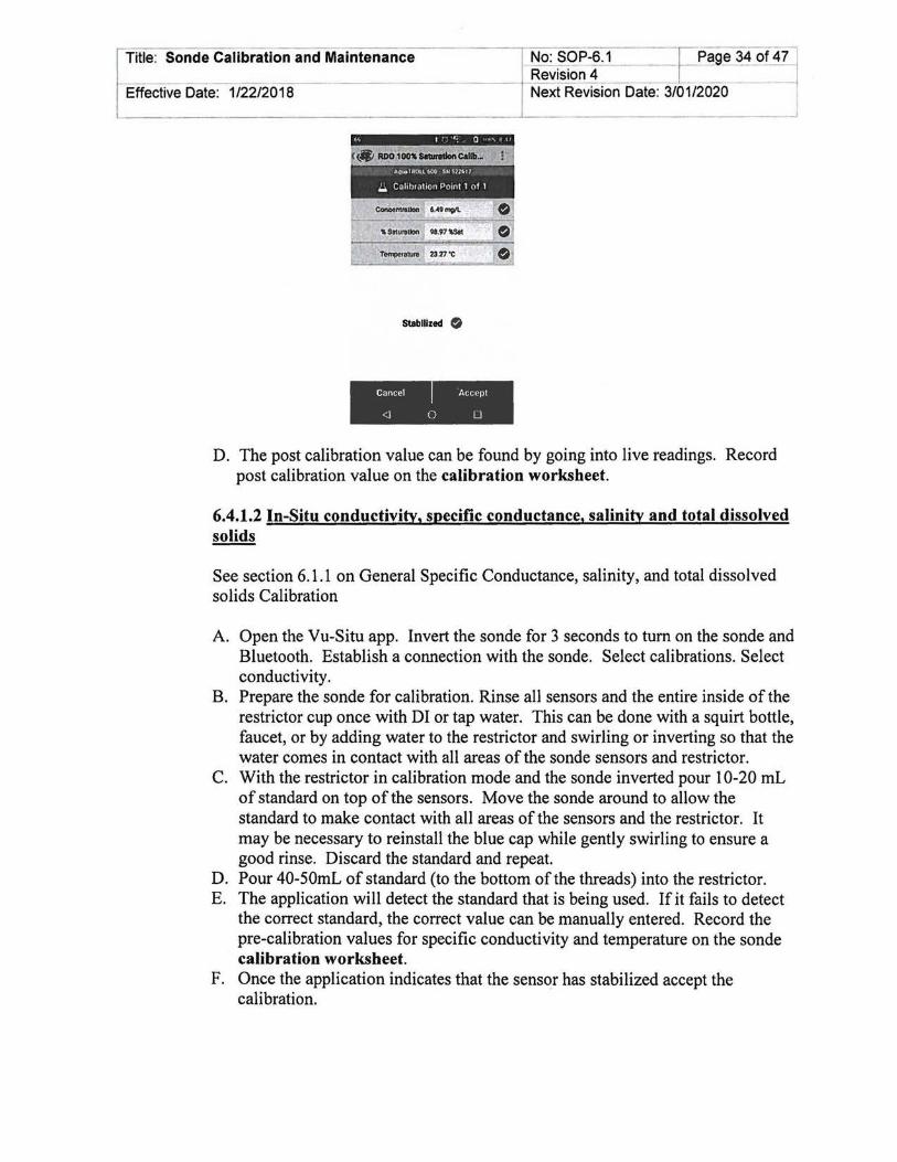
Title: Sonde Calibration and Maintenance No: SOP-6.1 ~Page 34 of 47 Revision 4 -- --
Effective Date: 1/22/2018 Next Revision Date: 3/01/2020
Stabilized $
Cancel Accept
<I 0 0
D. The post calibration value can be found by going into live readings. Record post calibration value on the calibration worksheet.
6.4.1.2 In-Situ conductivity, specific conductance, salinity and total dissolved solids
See section 6.1.1 on General Specific Conductance, salinity, and total dissolved solids Calibration
A. Open the Vu-Situ app. Invert the sonde for 3 seconds to tum on the sonde and Bluetooth. Establish a connection with the sonde. Select calibrations. Select conductivity.
B. Prepare the sonde for calibration. Rinse all sensors and the entire inside of the restrictor cup once with DI or tap water. This can be done with a squirt bottle, faucet, or by adding water to the restrictor and swirling or inverting so that the water comes in contact with all areas of the sonde sensors and restrictor.
C. With the restrictor in calibration mode and the sonde inverted pour 10-20 mL of standard on top of the sensors. Move the sonde around to allow the standard to make contact with all areas of the sensors and the restrictor. It may be necessary to reinstall the blue cap while gently swirling to ensure a good rinse. Discard the standard and repeat.
D. Pour 40-50mL of standard (to the bottom ofthe threads) into the restrictor. E. The application will detect the standard that is being used. If it fails to detect
the correct standard, the correct value can be manually entered. Record the pre-calibration values for specific conductivity and temperature on the sonde calibration worksheet.
F. Once the application indicates that the sensqr has stabilized accept the calibration.
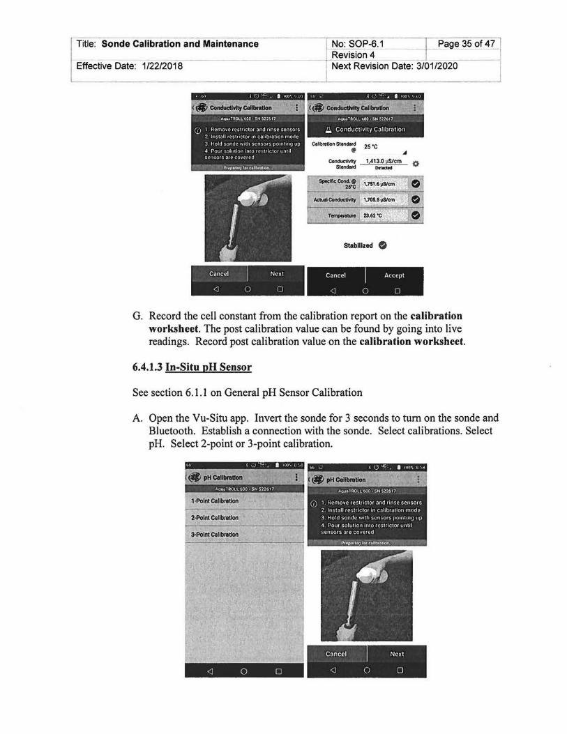
Title: Sonde Calibration and Maintenance l No: SOP-6.1 Revision 4
Effective Date: 1/22/20 ·1~8=--------------t-:-N7"e:....:..:.xt Revision Date: 3/01/2020
Stabilized 0
Cancel Next Cancel Accept
<l 0 0 <l 0 0
G. Record the cell constant from the calibration report on the calibration worksheet. The post calibration value can be found by going into live readings. Record post calibration value on the calibration worksheet.
6.4.1.3 In-Situ pH Sensor
See section 6.1.1 on General pH Sensor Calibration
A. Open the Vu-Situ app. Invert the sonde for 3 seconds to tum on the sonde and Bluetooth. Establish a connection with the sonde. Select calibrations. Select pH. Select 2-point or 3-point calibration.
tlfl pH Clllbnllon
1-Polnt calibration
2-Polnt calibration
3-Polnt Calibration
Cancel Next
<l 0 [J <l 0 0

Title: Sonde Calibration and Maintenance
Effective Date: 1/22/2018
J No: SOP~6. 1 ]~9~ 36 of 47 l . vision 4 · _J 1 Next Revision Date: 3/01/2020 /
B. For multi-point calibrations, start with pH 7. C. Prepare the sonde for calibration. Rinse all sensors and the entire inside of the
restrictor cup once with DI or tap water. This can be done with a squirt bottle, faucet, or by adding water to the restrictor and swirling or inverting so that the water comes in contact with all areas of the sonde sensors and restrictor.
D. With the restrictor in calibration mode and the sonde inverted pour 1 0~20 mL of standard on top of the sensors. Move the sonde around to allow the standard to make contact with all areas of the sensors and the restrictor. It may be necessary to reinstall the blue cap while gently swirling to ensure a good rinse. Discard the standard and repeat.
E. Pour 40-SOmL of standard (to the bottom of the threads) into the restrictor. F. Once the application indicates that the sensor has stabilized record the pH
reading, m v' and temperature on the calibration worksheet and accept the calibration.
G. Repeat steps C - F with the next standard.
• &9 c { j ~ , I ~t.[l ... 1 't•
pHBuller ---.::-':"7·00=:'7-- 0 Otlectod
Stabilized 0
Cancel Next
<] 0 0
pH Buller ---::1=0.=00":---- 0 Oetecled
Stabilized 0
Cancel Accept
<] 0 0
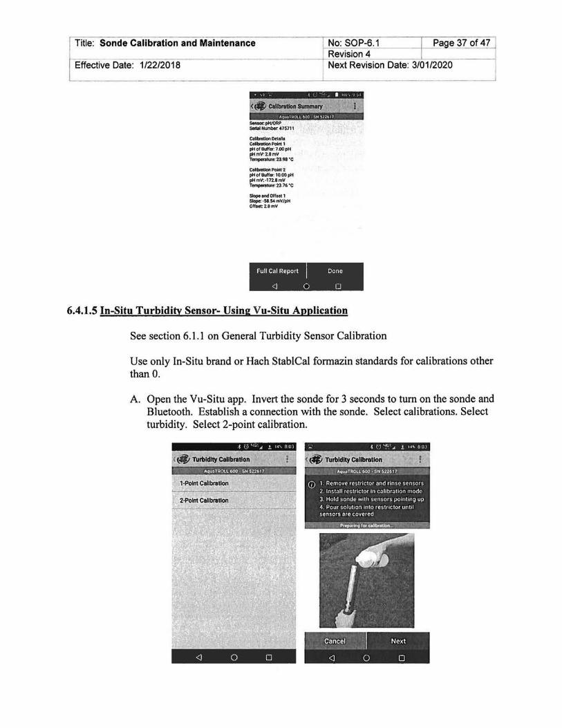
Title: Sonde Calibration and Maintenance No: SOP-6.1 I Page 37 of 47 Revision 4 I -- -
Effective Date: 1/22/2018 Next Revision Date: 3/01/2020
• Calibration SUmmary Aqu.aTHOlll':!OO • SN 52 :161 7
Sensor. pH/ORP Serial Number. 475711
Collbnttlon Details CoUbrotlon Point 1 pH of Buffer: 7.00 pH pHmV: 2.8mV Temperature: 23.98 ·c
Collbratlon Point 2 pH of Buffer: 10.00 pH pH mv: ·112.8 mv Tempenoture: 23.76 •c
Slope and Offaet1 Slope: ·58.54 mV/pH Ollaet:2.8mV
Full Cal Report Done
<J 0 0
6.4.1.5 In-Situ Turbidity Sensor- Using Vu-Situ Application
See section 6.1.1 on General Turbidity Sensor Calibration
Use only In-Situ brand or Hach StablCal formazin standards for calibrations other than 0.
A. Open the Vu-Situ app. Invert the sonde for 3 seconds to tum on the sonde and Bluetooth. Establish a connection with the sonde. Select calibrations. Select turbidity. Select 2-point calibration.
< (#J TUrbidity calibration
AQ1.UTR.O\.l6()0 • SN' 51:26.17
1·Polnt•Callbratlon
Cancel Next
<J 0 0

Effective Date: 1/22/2018
I No: SOP-6.1 ~ge 38 of 47 i I Revision 4 -----,
Next Revision Date: 3/01/2020 ----l Title: Sonde Calibration and Maintenance
B. Always start with 0 NTU. C. Prepare the sonde for calibration. Rinse all sensors and the entire inside of the
restrictor cup once with DI or tap water. This can be done with a squirt bottle, faucet, or by adding water to the restrictor and swirling or inverting so that the water comes in contact with all areas of the sonde sensors and restrictor.
D. With the restrictor in calibration mode and the sonde inverted pour 10-20 mL ofDI on top of the sensors. Move the sonde around to allow the DI to make contact with all areas of the sensors and the restrictor. It may be necessary to reinstall the blue cap while gently swirling to ensure a good rinse. Discard the D I and repeat.
E. Pour 40-50mL of DI (to the bottom of the threads) into the restrictor. F. The application will detect the standard that is being used. If it fails to detect
the correct standard the correct value can be manually entered. G. Once the application indicates that the sensor has stabilized record the pre
calibration turbidity value on calibration worksheet and accept the calibration. Discard the DI water.
H. Follow the prompts for the second standard. I. Gently swirl and/or invert the bottle of 100 NTU standard for approximately
30 seconds to mix the suspension. DO NOT shake the bottle of standard! This will suspend air bubbles in the solution and change the turbidity of the standard.
J. With the restrictor in calibration mode and the sonde inverted pour 10-20 mL of standard on top of the sensors. Move the sonde around to allow the standard to make contact with all areas of the sensors and the restrictor. It may be necessary to reinstall the blue cap while gently swirling to ensure a good rinse. Discard the standard and repeat.
K. Pour 40-50mL of standard (to the bottom of the threads) into the restrictor. L. The application will detect the standard that is being used. If it fails to detect
the correct standard the correct value can be manually entered. M. Once the application indicates that the sensor has stabilized record the pre
calibration turbidity value on calibration worksheet and accept the calibration. Discard the standard.

Title: Sonde Calibration and Maintenance No: SOP-6.1 Page 39 of47
- -----------------Effective Date: 1/22/2018
Revision 4 r ext Rev-is'-io_n_D- at_e_: 3- /-'-0-1/-2-02_0 ___ _
Turbidity Standard --=-O.:..:c0°:...:.N;;.;..TU;:;___ 0
TUrbidity 0.21 NTU
Stabilized 0
Cancel Next ---- .... ---~--
<J 0 0
6.4.2 In-Situ sonde Post Check
Turbidity Standard _ l.:.::0:::.:-0.0"-"0,.,.,N,:.-'TU'--- O Detected
Turbidity 124.10NTU
Stabilized 0
Cancel Accept -----------------
<1 0 0
For DO, install a wet sponge into the restrictor (see DO calibration). Make sure it is damp and not dripping. Install the end cap with one full rotation. Do not tighten. Allow 5 to 10 minutes to reach 100% saturation of the air within the chamber. Establish a connection with the Sonde in the Vu-Situ App. Select live readings. After the sonde has stabilized record the DO values and temperature in the post check section of the calibration sheet. See 6.1 General Post Deployment, Post Check for the other sensors.
6.4.3 In-Situ sonde Post Deployment Maintenance
After deployment and after the post check has been completed clean the sonde and the restrictor with cold water. If further cleaning is required refer to the more detailed cleaning procedures for each sensor outlined in 6.4.4.
6.4.4 In-Situ sonde Maintenance
Follow the maintenance schedule and procedures listed in the Operator's Manual, replacement kits, and/or sensor instruction sheets.
6.4.4.1 0-rings
The instrument has several 0-rings that can be maintained by applying silicone grease to new and old 0-rings. Check 0-rings for cracks or other damage and replace.

No: SOP-6.1 Page 40 of 47 I Revision 4 - ~ Next Revision Date: 3/01/2020 1 Effective Date: 1/22/2018
Title: Sonde Calibration and Maintenance
~---------------------------------------~----------------------------J
6.4.4.2 pH/ORP Sensor
If the ORP platinum electrode is dull or dirty, it can be cleaned with a swab and methanol or isopropyl alcohol. Rub the electrode gently until it is shiny. The pH sensor must be kept moist for the life of the sensor. The sensor fill solution has a shelf life of2 years. Replace the fill solution every 5 to 6 months or when: • The sensor fails to calibrate within the acceptable slope and offset range. • Sensor readings vary. • Readings during calibration at pH 7 are greater than+ 30m V or less than-30m V. • Sensor is slow to respond. If the sensor fails to calibrate after you replace the fill solution, replace the reference junction.
Replacing the Filling Solution:
A. Remove the sensor from the port. B. Install the dust cap on the connector end or wrap the connector end in
a paper towel to prevent solution from entering the connector. C. Unscrew the reference junction. D. Hold the sensor at an angle and shake out the old filling solution. E. Using the dispenser cap on the filling solution bottle, insert the tube into
the bottom of the empty reservoir. Squeeze a steady stream of solution into the reservoir until it overflows and no bubbles are observed. Continue to add solution while pulling the tube out of the reservoir.
F. Attach the reference junction to the sensor and hand-tighten until firmly attached. Some filling solution will overflow. Wipe the excess off the sensor body.
G. Soak the sensor in tap water for at least 15 minutes. H. Calibrate the sensor.
If necessary, thoroughly clean the sensor connector to remove filling solution: Using a disposable pipette, fill the connector with isopropyl alcohol (70% to 100% ), Shake to dry. Repeat 3 times. Dry overnight. When thoroughly dry, calibrate the sensor
Replacing the Junction
Replace the junction when the sensor fails to calibrate with a reasonable slope and offset, even after you have replaced the filling solution.
A. Unscrew the reference junction and discard. B. Replace the filling solution and screw in a new reference solution. C. Soak for 15 minutes, then calibrate the sensor.
Cleaning

Title: Sonde Calibration and Maintenance
~ctive Date: 1/22/2018
I No: SOP-6.1 I Page 41 of 47 I Revision 4 I I Next Revision Date: 3/01/2020
Begin with the gentlest cleaning method and continue to the other methods only if necessary. Do not directly wipe the glass bulb. To clean the pH sensor, gently rinse with cold water. If further cleaning is required, consider the nature of the debris
To remove crystalline deposits: • Clean the sensor with warm water and mild soap. • Soak the sensor in 5% HCl solution for 10 to 30 minutes. • If deposits persist, alternate soaking in 5% HCl and 5% NaOH solutions. To remove oily or greasy residue: • Clean the sensor with warm water and mild soap. • Methanol or isopropyl alcohol may be used for short soaking periods, up to 1 hour. • Do not soak the sensor in strong solvents, such as chlorinated solvents, ethers, or
ketones, such as acetone. To remove protein-like material, or slimy film: • Clean the sensor with warm water and mild soap. • Soak the sensor in 0.1 M HCl solution for 10 minutes and then rinse with
deionized water.
After performing any of these cleaning methods, rinse the sensor with water, then soak overnight in pH 4 buffer.
6.4.4.3 RDO Sensor
Routine Maintenance
A. Leave the sensor cap on. B. Rinse the sensor with clean water. C. Gently wipe with a soft cloth or brush ifbiofouling is present. D. If extensive fouling or mineral buildup is present, soak the sensor in
vinegar for 15 minutes, then soak in deionized water for 15 minutes.
Do not use organic solvents-they will damage the sensor cap. Do not remove the sensor cap when rinsing or brushing.
Cleaning the Optical Window
Clean the optical window only when changing the sensor cap.
A. Remove the cap. B. Gently wipe the sensing window with the supplied lens cloth.
Do not wet the lens with any liquid.
6.4.4.4 Conductivity Sensor

No: SOP-6.1 I Page 42 of 47 Revision 4 ---- ----
Title: Sonde Calibration and Maintenance
Effective Date: 1/22/2018 Next Revision Date: 3/01/2020
Cleaning
Begin with the gentlest cleaning method and continue to the other methods only if necessary. To clean the conductivity sensor face, gently rinse with clean, cold water. If further cleaning is required, consider the nature of the debris.
To remove crystalline deposits:
A. Clean the sensor face with warm water and mild soap. B. Use a soft brush to gently clean the sensor pins and temperature button.
Ensure removal of all debris around the base of the pins and button. C. If crystalline deposits persist, soak in 5% HCl for 10 to 30 minutes
followed by warm soapy water and soft brushing. D. If deposits persist, alternate soaking in 5% HCl and 5% NaOH solutions
followed by warm soapy water and soft brushing.
To remove oily or greasy residue:
A. Clean the sensor face with warm water and mild soap. B. Using a soft brush, gently clean the sensor pins and temperature button.
Ensure removal of all residue around the base of the pins and temperature button.
C. Isopropyl alcohol may be used for short soaking periods, up to one hour. D. Do not soak in strong solvents such as chlorinated solvents, ethers or ketones
(such as acetone).
To remove protein-like material, or slimy film:
A. Clean the sensor face with warm water and mild soap. B. Using a soft brush, gently clean the sensor pins and temperature button.
Ensure removal of all material/film around the base of the pins and temperature button.
C. Soak the sensor in 0.10% HCl for 10 minutes and then rinse thoroughly with distilled water.
6.4.4.5 Turbidity Sensor
Cleaning
The optical windows should be clear of foreign material. To clear material gently rub the sensing windows using clean water and a soft cloth or swab. Do not use solvents on the sensor.
Replacing Wiper Bristles

Title: Sonde Calibration and Maintenance I No: SOP-6.1 I Page 43 of 47 ! Revision 4 I
Effective Date: 1/22/2018 / Next Revision Date: 3/01/2020
Wiper bristles need to be replaced based on site conditions. In-Situ recommends replacing bristles at least every 12 months or when visibly bent, damaged, or fouled.
6.4.5 In-Situ Sonde Storage
6.4.5.1 Short Term (<1 Month)
The restrictor can be used as a storage cup. A. Remove the restrictor from the sonde body. B. Remove the blue end cap from the restrictor. C. Screw the blue end cap on to the restrictor end opposite of the flow-through holes. D. Pour 15 mL (5 oz.) of clean water (not DI) into the restrictor. E. Screw the restrictor on to the sonde.
6.4.5.2 Long Term (> 1 Month)
A. Remove the pH/ORP sensor and place a sensor port plug into the empty pH/ORP port.
B. Add a small amount of pH Storage Solution (00653 70) or pH 7 calibration solution (008321 0) to the sponge in the pH/ORP storage cap.
C. Place the cap firmly on the sensor. Use electrical tape to seal the cap to the sensor. D. Place a dust cap on the sensor connector. E. Remove the batteries from the sonde. F. Remove the restrictor from the sonde body. G. Remove the blue end cap from the restrictor. H. Screw the blue end cap on to the restrictor end opposite of the flow-through holes. I. Screw the restrictor on to the sonde. J. Place a dust cap on the sensor connector. K. Store the sonde and pH/ORP sensor in the box they arrived, at temperatures
between -5° to 65° C.
6.5 Onset HOBO DO Logger
6.5.1 Onset HOBO DO Logger Calibration
See section 6.1.1 for General DO sensor calibration
The logger uses a replaceable sensor cap that provides 6 months of continuous use. To install the sensor cap: A. Unscrew the protective guard covering the DO sensor. B. Remove the red dust cap that protects the sensor during shipping. C. Take the green sensor cap out of the canister. D. With the flat part of the DO sensor pointing down and the green sensor cap oriented
with the arrow up, slide the sensor cap over the sensor until it snaps in place. The cap should be snug against the logger housing without any gaps.

~~ SOP-6.1 --1-Page 44 of47J Revision 4
1 Next Revis1on Date: 3/01/2020
Title: Sonde Calibration and Maintenance
Effective Date: 1/22/2018
E. Screw on the protective anti-fouling guard
To calibrate, use the Lab Calibration tool in HOBOware following these steps:
A. Open HOBOware and establish computer connection with the logger using a HOBO base station or HOBO waterproof shuttle. The optical ports on the logger are located under the pointed cap.
B. Stop logging if the sensor is currently logging C. From the device menu, click "Lab Calibration" D. The current gain and offset adjustments are displayed in the top pane of the Lab
Calibration window along with the date and time the last lab calibration was completed (if applicable). Completion of Steps 1-3 in the Lab Calibration tool will result in new gain and offset adjustment values based on the current logger conditions.
E. Step 1: 100% Saturation 1. In the Lab Calibration window enter the barometric pressure for your current
location. 2. Make sure the logger either has the protective guard or the anti-fouling guard
installed so that the sensor is covered. 3. Wet the small sponge with fresh water. Squeeze out any excess water. 4. Place the sponge in the end ofthe calibration boot. 5. Insert the logger in the calibration boot so that there is approximately a I em
overlap between the end of the boot and the body of the logger. This will ensure there is enough space between the end of the logger and the sponge (the logger should not be pressed up tightly against the sponge).
6. Wait approximately 15 minutes until the logger reaches temperature equilibrium (and less than 30 minutes so the logger does not go to sleep).
7. Click the "Get DO value from the logger" button to display the 100% saturation results. The results are updated each time you click this button. Click several times to confirm consistent readings.
8. When the DO value displayed in the "Step 1: 100% Saturation" tab stabilizes, click the Next button to proceed.
F. Step 2: 0% Saturation (optional). Recommended if DO levels below four (4) milligrams per Liter (mg/L) are expected
I. If DO levels above four ( 4) mg/L are expected, click "Skip this Step" button. Otherwise continue with the following procedure
2. Make sure the logger either has the protective guard or the anti-fouling guard installed.
3. Pour the sodium sulfite into the 3-inch beaker so that it is about two-thirds full 4. Place the sensor end of the logger into the solution so that the entire protective
guard or anti-fouling guard and at least 2.5 centimeters (em) ofthe logger body are submerged in the beaker. Allow it to rest on the bottom of the beaker.
5. Wait for approximately 15 minutes until the logger reaches temperature equilibrium (and less than 30 minutes so the logger does not go to sleep)

Title: Sonde Calibration and Maintenance
~ctive Date: 1/22/2018
I No: SOP-6.1 I Page 45 of 47 l Revision 4 I / Next Revision Date: 3/01/2020
6. Click the "Get DO value from the logger" button to display the 0% saturation results. As with the 100% calibration, you may click this button multiple times to confirm consistent measurements. When you are satisfied with the results in the "Step 2: 0% Saturation" tab, click the Next button to proceed to "Step 3: Finish"
7. Document the calibration date and time and calibration coefficient on the DO Logger Deployment Form.
G. Step 3: Finish 1. The results from the first two steps are displayed along with the overall
calibration results and the new gain and offset adjustment values. 2. Click "Send Calibration to Logger" button. The logger is now calibrated based
on the new values 3. The Calibration will take effect when the logger is launched. Refer to the
SWQB's Sonde Deployment SOP (SOP 6.2) for use and data collection in the field.
6.5.2 Onset HOBO DO Logger Post Deployment Check
Record the DO and temperature with a sonde that has been calibrated at the deployment elevation at retrieval, and note these values on the DO Logger Deployment/Upload/ Retrieval Form. If, upon retrieval, the sensor is either exposed to the air or buried in sediment, excavate or submerge the logger and place it in water along with a locally calibrated sonde. Leave the logger in water until at least one data point has been recorded. At the same time, record Specific Conductance, DO concentration, DO % saturation, and temperature from the sonde. If the stream has gone dry and no environmental water is available, use a bucket if possible. If neither environmental water nor a bucket of water is available, place the calibration boot with the dampened sponge over the sensor, wait at least 15 minutes, and allow the logger to record at least one data point of 100% saturated air. This is solely to be able to check the data for drift. Note: DO concentration and temperature values are required for DO% calculations and data management purposes.
6.5.3 Onset HOBO DO Logger Maintenance
The logger is equipped with a replaceable sensor cap that provides six months of continuous use. The sensor cap expires 7 months after the cap is initialized to allow a month buffer between lab calibration and deployment. The sensor should only be cleaned with a sensor cap installed. To clean the sensor cap within the active 6-month period, refer to the Onset manual.
The temperature portion of the DO Logger is internal and requires no maintenance or calibration.
6.5.4 Onset HOBO DO Logger Storage

Title: Sonde Calibration and Maintenance I
No: SOP-6.1 [=Page 46 of 47 j R~~~n4 ~ I
f--E_,.ff,.,..e-c-ti-ve---=-oa_t_e_: -1....,/2--:2-/2,...-0-1-,-8------------, Next Revision Date: 3101/2020 ----j
Between deployments, keep the logger in the calibration boot. Wet the sponge with tap water, place the sponge in the end of the calibration boot, and then insert the logger in the boot. The DO sensor should be stored with a calibration cap installed (preferably NOT a new un-initiated sensor cap).
6.6 Onset HOBO Conductivity Logger
6.6.1 Onset HOBO Conductivity Logger Calibration and Post Deployment Check
The Conductivity Logger sensor is factory-calibrated and cannot be adjusted. Calibration verification checks are performed against a calibrated sonde in ambient water at both deployment and retrieval. The conductivity calibration readings should be the actual conductivity without temperature compensation (not specific conductance at 25°C) taken at the datalogger's sampling time, and should be recorded on the Conductivity Logger Deployment Form. Allow enough time for the conductivity logger temperature to stabilize (approximately 15 minutes).
6.6.2 Onset HOBO Conductivity Logger Maintenance
The Conductivity Logger requires little maintenance, only gentle cleaning of the sensor following deployments. To clean the sensor, mix several drops of dish detergent or biodegradable soap in a cup of tap water with a clean cotton swab. Clean the sensor face using the cotton swab and then rinse the sensor with clean or distilled water. Do not scratch the sensor face with a sharp tool. Do not use solvents that are incompatible with the logger housing materials. See the manual for more information.
6.6.3 Onset HOBO Conductivity Logger Storage
In between deployments and for long-term storage, place the protective cap over the sensor face. Care should be taken that the unit is stored in a box or container that will prevent damage or abrasion to the unit.
7.0 Related Forms
YSI!Hydrolab/In-Situ Sonde Calibration Form Onset DO Logger Deployment Form (see SOP 6.2) Onset Conductivity Logger Deployment Form (see SOP 6.2) Stream/River Field Data Form (see SOP 8.0)
8.0 Revision History
Revision 4- January 2017- updated to incorporate In-Situ sondes and HOBO Conductivity Loggers, added post check procedures and in-calibration range table, formatted to SOP 1.1 (2017).
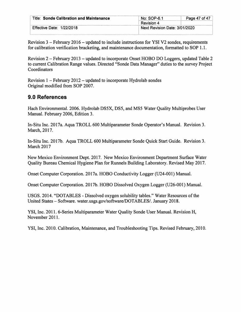
Title: Sonde Calibration and Maintenance I No: SOP-6.1 -j- Page 47 of 47 I
----:::---c-~::-:-=-::-:-::--------------~-=R...:.:e::...:v..:.::is::::io:.=-n=-::4'-:---=----::-:~~=-=------l Effective Date: 1/22/2018 I Next Revision Date: 3/01/2020
I
Revision 3 - February 2016 -updated to include instructions for YSI V2 sondes, requirements for calibration verification bracketing, and maintenance documentation, formatted to SOP 1.1.
Revision 2 -February 2013 -updated to incorporate Onset HOBO DO Loggers, updated Table 2 to current Calibration Range values. Directed "Sonde Data Manager" duties to the survey Project Coordinators
Revision 1 -February 2012- updated to incorporate Hydrolab sondes Original modified from SOP 2007.
9.0 References
Hach Environmental. 2006. Hydrolab DSSX, DSS, and MSS Water Quality Multiprobes User Manual. February 2006, Edition 3.
In-Situ Inc. 2017a. Aqua TROLL 600 Multiparameter Sonde Operator's Manual. Revision 3. March, 2017.
In-Situ Inc. 20 17b. Aqua TROLL 600 Multi parameter Sonde Quick Start Guide. Revision 3. March 2017
New Mexico Environment Dept. 2017. New Mexico Environment Department Surface Water Quality Bureau Chemical Hygiene Plan for Runnels Building Laboratory. Revised May 2017.
Onset Computer Corporation. 2017a. HOBO Conductivity Logger (U24-001) Manual.
Onset Computer Corporation. 20 17b. HOBO Dissolved Oxygen Logger (U26-00 1) Manual.
USGS. 2014. "DOT ABLES- Dissolved oxygen solubility tables." Water Resources of the United States- Software. water.usgs.gov/software/DOTABLES/. January 2018.
YSI, Inc. 2011. 6-Series Multiparameter Water Quality Sonde User Manual. Revision H, November 2011.
YSI, Inc. 2010. Calibration, Maintenance, and Troubleshooting Tips. Revised February, 2010.