
Field Guide to Proper Installation, Calibration, and ...infohouse.p2ric.org/ref/50/49029.pdf ·...
44
Field Guide to Proper Installation, Calibration, and Maintenance of Soil Moisture Sensor Control Systems in Residential Florida Landscapes 2007
-
Upload
truongcong -
Category
Documents
-
view
261 -
download
0
Transcript of Field Guide to Proper Installation, Calibration, and ...infohouse.p2ric.org/ref/50/49029.pdf ·...

Field Guide to Proper Installation,
Calibration, and Maintenance of Soil Moisture Sensor
Control Systems in Residential Florida Landscapes
2007

Produced for the St. Johns River Water Management District
by The University of Florida Program for Resource Effi cient Communities
DISCLAIMER:
The University of Florida does not in any way endorsespecifi c brands of soil moisture sensor control systems. This document only endorses specifi c best practices for
proper installation, calibration, and maintenance of soil moisture sensor control systems.

i
Table of ContentsI. Introduction .................................................................................................1
A. The Role of the Modern Soil Moisture Sensor in Florida ............................................................. 1B. University of Florida Research..................................................................................................... 2
II. Installation .................................................................................................5Step 1: Establish the Sensor Location ............................................................................................. 5Step 2: Install the Sensor ............................................................................................................... 12Step 3: Install the Controller ........................................................................................................... 21Step 4: Connect the Wiring ............................................................................................................ 22
III. Calibration ..............................................................................................25Step 1: Establish Controller Set-point ............................................................................................ 25Step 2: Calibration.......................................................................................................................... 26
IV. Maintenance ...........................................................................................29A. Evaluate Soil Moisture Sensor Functioning ............................................................................... 29B. Other Information ....................................................................................................................... 31
V. Troubleshooting .......................................................................................33Important Reminders...................................................................................................................... 33
VI. References and Resources....................................................................35A. Irrigation Scheduling .................................................................................................................. 35B. General Irrigation ...................................................................................................................... 35C. UF Soil Moisture Sensor Research ........................................................................................... 35D. Water Effi ciency ......................................................................................................................... 35
VII. Appendices............................................................................................37Appendix A: Where to Install a Soil Moisture Sensor (SMS).......................................................... 37Appendix B: Irrigation scheduling per irrigation event for Florida turfgrasses (min) ...................... 38Appendix C: Monthly Net Irrigation Requirements for Florida ........................................................ 39

ii

Introduction
1
I. IntroductionA. The Role of the Modern Soil Moisture Sensor in FloridaWater is an extremely valuable, yet seriously stressed resource in Florida. Nevertheless, in-ground time-controlled irrigation systems that use potable water are standard in the landscapes of newly built homes. Ideally, homeowners adjust their irrigation time clocks in response to seasonal weather patterns. However, homeowners often make no adjustments, leaving their time clocks set at fi xed watering levels regardless of plant water requirements. As a result, residential irrigation systems frequently apply signifi cantly more water than landscapes require.
Conventional irrigation time clocks used in residential landscapes allow irrigation at scheduled times for specifi ed periods of time. For example, a controller can be scheduled to initiate a 15-minute irrigation event every Monday and Friday at 6:00 AM. These time clocks do not account for weather conditions and will irrigate at the scheduled time even if it is raining. To minimize this unnecessary irrigation, Florida Statute 373.62 requires that all newly-installed residential irrigation systems have an add-on rain shutoff device (rain sensor) that bypasses time-scheduled irrigation events during, and for a period after, rain events. While rain sensors improve the water-use effi ciency of time-controlled irrigation systems, time clocks are still programmed based on estimates of landscape water needs rather than actual landscape conditions.
Soil moisture sensor (SMSs) controllers measure soil moisture content where it is most vital to plants: in the active root zone. SMS systems connect to conventional irrigation time clocks and check soil moisture content prior to scheduled irrigation events. If the SMS controller determines that soil moisture content is above a user-defi ned set-point, the irrigation cycle is bypassed. This allows SMS controllers to not only bypass irrigation during rainy periods, but also to minimize irrigation when plants do not require additional water. A properly working SMS controller does not stress plants or decrease turfgrass quality because it allows the irrigation system to apply the amount of water actually needed to meet plant water requirements.
Figure 1 shows the circuit created by a SMS control system. If moisture is above the set-point, the circuit in the SMS controller is left open and no irrigation occurs. If the soil moisture is below the set-point the circuit is closed and the scheduled irrigation even occurs.
Different SMS technologies are used to measure soil moisture content in residential landscapes. One is an improved granular matrix sensor (GMS) technology, which has been used in agricultural irrigation systems for decades. Some modern soil moisture sensors use electrical conductivity to measure soil moisture content. Two types of SMSs use this technology: a time domain transmissivity (TDT) sensor and a time domain refl ectometry (TDR) sensor. All sensor types are discussed in general terms in this fi eld guide.
General diagram of an irrigation system with a Figure 1. soil moisture sensor (SMS) control system.

Introduction
2
Useful Terms
Evapotranspiration (ET) – A combination of water transpired from vegetation and evaporated from the soil and plant surfaces. Also known as consumptive use.
Field capacity – The moisture remaining in the soil following wetting and gravitational drainage until water has ceased drainage.
Irrigation zone – An area in a landscape that is irrigated by a single zone (solenoid) valve.
Net irrigation requirement – The amount of water needed to replace water lost through evapotranspiration, minus the amount of rainfall that contributes water to the plant root zone (i.e. effective rainfall).
Plant water requirement – The amount of water needed to replace water lost through evapotranspiration.
Representative area – An area possessing the average qualities of the irrigation zone(s) controlled by the SMS control system.
Soil Moisture Sensor - The soil moisture sensor probe that is installed in the ground within the root zone.
Soil Moisture Sensor Controller - Collective term sometimes used for the entire SMS system.
B. University of Florida ResearchBeginning in 2004, a research group in the Agricultural & Biological Engineering Department at the University of Florida (UF) initiated a series of ongoing studies on soil moisture sensors (SMSs) in turfgrass. These studies have been conducted in both highly-controlled research facilities and in homeowner landscapes. To date, all studies have shown that SMS controllers produce substantial water savings in comparison to conventional time clocks and rain sensors, while maintaining acceptable turf quality.
Study 1In the fi rst study, in a controlled research environment in Gainesville, FL (2004-2005) four SMS controllers were tested:
Acclima RS500,• RainBird MS-100,• WaterWatcher DPS-100, and• Irrometer 200SS-5.•
Rainfall during this study period was average to above average, resulting in high sensor-based water savings. Treatments were compared to a 2-day-per-week time-based irrigation schedule based on Dukes and Haman (2002a), using no sensor technology. All four SMS controller treatments applied less irrigation water than the time-based schedule with no sensor (Table 1). Three of the SMS controllers (Acclima RS500, RainBird MS-100, and WaterWatcher DPS-100) signifi cantly outperformed a rain shut-off device set at ¼” (6 mm): the SMS-controlled irrigation application reduction ranged from 70% to 92% while rain sensors averaged a 34% savings (Cardenas-Lailhacar, in press).

Introduction
3
Two other sensors, the BaseLine WaterTec S100 and the Lawn Logic LL-1004, have been added to ongoing research at the Gainesville, FL facility.
Study 2In the second study at a controlled research environment in Citra, FL (2006), two SMS controllers were tested: the Acclima RS500; and the LawnLogic LL-1004. Rainfall during this study was below average, resulting in lower SMS-controlled water savings compared to Study 1 savings. These water savings ranged from 10% to
28% (Table 2). Rain sensors saved 11% to 23% compared to the conservative irrigation schedule (Shedd et al., 2007).
Study 3The third study tested one sensor controller, the Acclima RS500, on residential landscapes in the City of Palm Harbor, FL. Preliminary results show that sensors are successful for irrigation water-use savings at the single family home level. From June 2006 through March 2007, homes with soil moisture sensors demonstrated water savings of 51% compared to homes with an irrigation time clock only (Haley and Dukes, 2007).
Table 1: Water Savings In Wet Conditions in a Research Setting
Treatment Percentage of Water Saved
2 days/week without sensor 0%
2 days/week with rain sensor 34%
2 days/week SMS average 72%
* SMS = Soil moisture sensor
Table 2: Water Savings In Dry Conditions in a Research Setting
Treatment Percentage of Water Saved
2 days/week without sensor 0%
2 days/week with rain sensor 10–23%
2 days/week SMS average 10–28%
* SMS = Soil moisture sensor

Introduction
4
DisclaimerProcedures for proper installation, calibration, and maintenance vary by SMS brand. Generally, each manufacturer’s installation manual provides adequate instructions for effective installation and these manuals should be referenced for specifi c instructions, especially for wiring, calibration, and troubleshooting. Valuable lessons have been learned during testing conducted at the University of Florida (UF) that can provide additional guidance. This fi eld guide describes these lessons and other information required for general best practices. However, installers and maintenance professionals should always refer to the most current manufacturer’s installation manual for model-specifi c instructions.

Installation
5
II. InstallationThere are four main installation steps outlined here. These are:
Establish the sensor location1.
Install the sensor2.
Install the controller3.
Connect the wiring4.
Step 1: Establish the Sensor LocationSMSs are most effective when placed in a location representative of the zone(s) that the sensor is controlling. If one sensor is being used for the entire landscape (the sensor is controlling multiple zones), the average water requirement of the entire landscape should be considered as the baseline. If multiple sensors are being used in one landscape (i.e. one sensor per zone), each sensor should be placed in an area representative of the specifi c zone it is controlling.
When used to control an entire irrigation system with only one sensor, SMS controllers should be installed in an irrigation zone for turfgrass. Instructions in this fi eld guide focus on landscapes comprised primarily of turfgrass. Typically, turfgrass will need more frequent irrigation than most other plant types in a landscape. Therefore, if turfgrass watering requirements are met, other plants in the landscape will receive suffi cient irrigation, presuming that all irrigation zones are properly designed and scheduled for the associated plant materials. Care must be taken before using SMS control systems on stress prone plants such as some annuals. If SMS controllers are being used for landscape plants, trees, or other types of groundcover, installers should refer to the manufacturer’s installation manual for location instructions and specifi cations.
Variations in soil type and condition, adjacent land use, shading, and drainage patterns all can cause a sensor to read an unrepresentative soil moisture content, which can result in too much or too little irrigation. If one area does not represent the average condition of the SMS-controlled area, SMS placement in that location should be avoided.
Location in the landscape – Soil moisture sensors should be placed at the driest location relative to the average of the SMS-controlled zone(s). These driest locations may include:
areas with signifi cant sun exposure1.
lot-specifi c high elevation points2.
Depth in the ground – Sensor probes should be placed within the root zone, in contact with relatively undisturbed soil that is representative of the irrigated landscape area. Contact with disturbed soil with a higher (or lower) amount of void space will likely result in unrepresentative soil moisture content readings. However, if the soil in the entire landscape is disturbed (i.e., fi ll material used to elevate and level a new construction site), a disturbed area would be representative.

Installation
6
A. Optimal Installation AreasThe following are optimal areas for sensor installation:
In the turfgrass root zone• (Figure 2), if turfgrass is used as the representative plant type.
Purpose: Provide suffi cient irrigation to the area with the greatest water requirement. Generally, turfgrass will have the highest water requirement relative to other landscape plants. If the turfgrass requirements are met, other plant water requirements should also be met, presuming that all irrigation zones are properly designed and scheduled for the associated plant materials.
In a relatively sunny area• , if full sun is representative of the landscape.
Purpose: Provide suffi cient irrigation to the area with the greatest water requirement. Often, landscapes have turfgrass lawns in full sun. These areas have higher evapotranspiration (ET) rates and therefore, higher water requirements. Also, in new landscapes, these areas may have poor soil that does not hold water well.
In the driest representative area possible• , considering all other factors.
Purpose: Provide suffi cient irrigation to the area with the greatest water requirements. While other areas might receive more water than required, the sensor should not be installed in an area where it will bypass irrigation events necessary to meet the landscape's water requirements as a whole.
In the center of the irrigation zone• , or in an area receiving an average, or slightly less than average, amount of irrigation relative to other irrigated areas in the landscape.
Purpose: Ensure that the SMS is not located in an area with a greater than average soil moisture content. In some cases, irrigation distribution may be nonuniform and sensor placement in an area with higher relative irrigation could result in too many bypassed irrigation events, preventing plants in some areas from receiving the irrigation needed to meet their water requirement.
B. Areas to Avoid – GeneralWhen establishing the SMS location, certain areas and site conditions should be avoided.
INSTALL the sensor at least 5 feet away from: To avoid:
a property line• ............................................................ irrigation overspray from a neighbor’s yardan impervious surface• ................................................ runoff from impervious surfaces and compacted soil around
impervious surfacesa structure (e.g., house, porch, shed, etc.).• ............... compacted soil, shade, and runoffa depression/swale• .................................................... naturally high soil moisture content areas
INSTALL the sensor at least 3 feet away from: To avoid:
a plant bed• ................................................................. higher runoff, shade, and unrepresentative plant roots
Bermudagrass root zone.Figure 2.

Installation
7
C. Areas to Avoid – High MoistureSome areas in the landscape can have a higher moisture content due to increased water infl ow or reduced water outfl ow. For example, directed stormwater runoff can cause an area to have a higher moisture content, while shade can cause the same effect by reducing evapotranspiration. These areas with a higher moisture content relative to the surrounding landscape should be avoided.
INSTALL the sensor at least 5 feet away from: To avoid:
a downspout• .............................................................. areas with higher amounts of infl owing stormwater relative to the rest of the landscape
an overhang• ............................................................... areas with higher or lower amounts of infl owing stormwater relative to the rest of the landscape
a hose bib• .................................................................. areas with higher amounts of infl owing water relative to the rest of the landscape
an air conditioner condensate line• ............................. areas with higher amounts of infl owing water relative to the rest of the landscape
the dripline of a tree canopy• ...................................... areas with a lower ET rate and higher moisture content (unless SMS is specifi cally used for trees)
a shaded north side of the home (if possible)• ............ areas with a lower ET rate and higher moisture content
D. Areas to Avoid – Disturbed Sites and SoilsIn some areas it is diffi cult to tell if the soil has been, or will be, compacted. Installers should use their best knowledge of the landscape history and projected use to determine the SMS location. If it is known that the soil has been, or will be, compacted in one particular area, the SMS should be installed elsewhere.
INSTALL the sensor at least 4 feet away from: To avoid:
a construction road• .................................................... compacted soils and runoff from compacted soils
INSTALL the sensor at least 3 feet away from: To avoid
an area with plant debris (e.g., tree stump)• ............... compacted soils and materials intermixed with soils that are unrepresentative of the landscape as a whole
an area with fi ll dirt (if fi ll dirt is unrepresentative• of the entire landscape) ............................................. soils that are unrepresentative of the landscape as a whole
buried material (e.g. cable, water or sewer line)• ........ soils and materials that will result in a soil moisture reading that is unrepresentative of the landscape as a whole or that may be disturbed in the future due to maintenance or repair
Note: • Check with local building codes before digging and installation of the irrigation system. • See Appendix A for a condensed table containing these priorities for determining SMS installation
location.

Installation
8
E. Landscape Examples
To better understand how these rules should be applied, three different landscape installation examples are shown on the following pages. The three depicted conditions are:
a typical landscape,1.
a Florida Water Star2. SM landscape, and
a preserved vegetation landscape.3.
In all three examples:
Green dotted areas are 1. optimal locations for SMS placement.
Blue striped areas are 2. secondary locations that might be appropriate in some cases.
Red wavy areas are 3. not suitable SMS locations.
Drawings are not to scale, to emphasize landscape features. Note: Specifi c site features and conditions could preclude installation in areas that appear to be optimal or
secondary installation locations. Always perform a site inspection to determine if any site specifi c conditions make an area less suitable for sensor probe installation.

Installation
9
In a Typical Landscape
Figure 3 depicts a lot with typical landscaping characterized by large turfgrass areas (greater than 60% of the entire landscape) and very few trees. There are many optimal sensor locations in this landscape, and it should be relatively easy to determine the best location within a short period of time. A newly developed landscape of this type will have fi ll material that must be considered during SMS installation.
LegendGreen dotted areas: Optimal locations for SMS placement.
Blue striped areas: Secondary locations that might be appropriate in some cases.
Red wavy areas: Not suitable SMS locations.
Example of a typical residential landscape.Figure 3.
N

Installation
10
In a Florida Water StarSM Landscape
Figure 4 depicts a hypothetical Florida Water Star landscape, composed of 60% or less turfgrass and 40% or greater planting beds, natural areas, or drought tolerant groundcovers. Reduced turfgrass area decreases the number of optimal SMS locations. There are optimal areas in the front yard, but fewer such areas exist throughout the Florida Water Star landscape, compared to the typical landscape. Selection of a sensor location in this type of landscape might require more attention than in a typical setting.
LegendGreen dotted areas: Optimal locations for SMS placement.
Blue striped areas: Secondary locations that might be appropriate in some cases.
Red wavy areas: Not suitable SMS locations.
Example of a Florida Water Star (water effi cient) landscape.Figure 4.
N

Installation
11
In a Preserved Vegetation Landscape
Figure 5 depicts a landscape with a high percentage of preserved vegetation. This landscape has more shaded areas, less turfgrass, and potentially higher soil moisture content. Because of the landscape layout, the optimal areas for SMS installation might be considered secondary areas in other landscapes. However, the goal is to place the SMS in a representative area. If the landscape only has secondary areas, the SMS should be installed in an area that will ensure all areas receive adequate irrigation.
LegendGreen dotted areas: Optimal locations for SMS placement.
Blue striped areas: Secondary locations that might be appropriate in some cases.
Red wavy areas: Not suitable SMS locations.
Example of a landscape with preserved vegetation.Figure 5.
N

Installation
12
F. Include SMS Location in New Landscape PlansSpecifying the SMS location in the landscape and irrigation design plan prior to installation can help streamline the installation process and reduce human error in the fi eld. If the location is predefi ned, the installer will spend less time surveying the landscape to determine an optimal sensor location. Nevertheless, the predefi ned location should be checked according to the Step 1: “Establish Sensor Location” instructions to ensure that unforeseeable factors do not make the area a poor choice for a SMS location.
G. Mark and Measure the Sensor LocationDocumentation of the sensor location can make future maintenance easier by providing a record of the SMS location to future homeowners, irrigation contractors, and maintenance professionals. Foremost, the SMS installer should specifi cally mark the sensor location on a copy of the as-built irrigation plan and display the plan adjacent to the irrigation timer. Additionally, installers should measure and record the distance and approximate angle from the SMS to two permanent points in the landscape (triangulation).
Step 2: Install the SensorBecause a sensor’s installation orientation depends upon its type, size, and shape, installers should always refer to the manufacturer’s installation manual during installation of the sensor. Until more research data regarding sensor installation become available, the sensor should be installed in the turfgrass root zone. In new landscapes with turfgrass, the SMS will often be installed prior to installation of the turfgrass sod. In this case, the sensor should be buried in the soil to a depth of approximately 3" and the turfgrass sod laid on top. For installation in existing turfgrass, an area of sod must be removed for SMS installation, and a trench must be dug into the adjacent sod to run the SMS wiring. The following installation instructions suggest that a wiring trench be dug after SMS installation. It is perfectly reasonable to dig the hole for the SMS and the trench at the same time and then install the sensor and wiring.
Note: • Always use a square-point ditching shovel for SMS installation (Figure 6). • Always check for proper system operation before burying the sensor probe and wiring.
Square point ditching shovel Figure 6. required for SMS installation.

Installation
13
A. Sensor TypesAt the time of this writing, three types of residential sensor probes are commercially available in Florida: (1) fl at, (2) node, and (3) rod. Installation procedures vary by type.
1. Flat sensor probes
Two types of long, fl at sensor probes are commonly found. Sensors with this type of probe typically use time domain transmissivity (TDT) to measure soil moisture content. Orientation should occur as follows:
Exposed wave guides – If the sensor probe is long, fl at, and has exposed rounded wave guides (steel rods), it should be installed horizontally with the wide side facing up (Figure 7).
Encased wave guides – If the sensor probe is long, fl at, and has a solid surface encasing the wave guides, it should be installed horizontally with the thin side facing up (Figure 8).
Flat Probes in New Landscapes
In landscapes with new turfgrass sod being installed, the sensor should be buried approximately 3" deep in the soil and the turfgrass sod placed on top of the soil as follows:
Dig an 8" by 8" hole, 3" deep.1.
Insert the sensor into the bottom of the hole according to the 2. sensor orientation specifi cations (Figure 9).
Dig the trench for the wiring connection (See Section B), 3. connect wiring according to the manufacturer’s installation manual, and check for proper SMS controller functioning.
Fill in the hole and trench, completely covering the sensor and 4. wiring.
Mark the sensor location with a fl ag to prevent damage during 5. the sod installation.
Install the turfgrass sod, pressing fi rmly over the sensor.6.
Probe with exposed wave guides.Figure 7. Probe with encased wave guides.Figure 8. (Photo courtesy of Base Line)
Installation of fl at probe SMS Figure 9. in new landscape (bare soil).

Installation
14
Flat Probes in Existing Landscapes
Two methods can be used to install fl at sensors in existing landscapes.
Option 1: Bury the SMS in a shallow hole by rolling back a square of turfgrass.
Using a square ditching shovel, cut a square piece of turfgrass to a depth of 3" that is large 1. enough to cover the entire probe (Figure 10).
Remove the square of turfgrass and soil by rolling it back, exposing the soil underneath (Figure 2. 11).
Place the sensor on top of the soil and gently press it into the soil (Figure 12).3.
Dig the trench to run wiring (See Section B), make the connections according to the 4. manufacturer's specifi cations, and check for proper SMS controller functioning.
Roll the turfgrass back on top of the sensor (Figure 13).5.
Cutting a square of turfgrass Figure 10. large enough to cover entire probe.
Turfgrass square rolled back.Figure 11.
SMS installed in root zone by "roll Figure 12. back" method.
Turfgrass rolled back over sensor.Figure 13.

Installation
15
Gently compact the turfgrass and soil plug, making sure that there are no channels that will allow 6. water to seep in and pool around the SMS (Figure 14). Additional soil can be added on top of the sensor location so that it may wash into any remaining gaps.
Option 2: Slide the SMS into the sidewall of a hole by cutting the turfgrass roots. •
Dig an 8" by 8" hole, 6" to 8" deep, ideally creating a plug that can be pulled out whole (Figure 1. 15).
Horizontally cut the turfgrass roots in an area large enough to fi t the sensor into the wall of the 2. hole at a depth of approximately 3" using a “metal slicing tool” and mallet (Figure 16).
Removal of turfgrass and soil plug.Figure 15. Root cutting procedure preparing soil Figure 16. for SMS installation.
Gently compacting the turfgrass area.Figure 14.

Installation
16
In its specifi ed orientation, slide sensor into cut area within the root zone (Figure 17).3.
Gently compact the soil above the sensor to ensure that there is suffi cient contact between the 4. sensor probes and the soil (Figure 18).
Dig the trench to run wiring (See Section B), make the connections according to the 5. manufacturer's specifi cations, and check for proper SMS controller functioning.
Replace the removed turfgrass and soil plug (Figure 19). 6.
Gently compact the turfgrass and soil plug, making sure that there are no channels that will allow 7. water to seep in and pool around the SMS. Additional soil can be added on top of the sensor location so that it may wash into any remaining gaps.
Compaction of soil around sensor to Figure 18. reduce void space and ensure adequate connection between SMS and soil.
Soil and turfgrass plug replaced, Figure 19. covering SMS prior to burying wire.
SMS installed within root zone.Figure 17.

Installation
17
2. Node Probes
SMSs with node probes should be installed vertically within the root zone. Sensors with this type of probe typically use granular matrix technology to measure soil moisture content. Because this type of sensor might have additional specifi cations, always refer to the manufacturer’s installation manual. Figure 20 shows a granular matrix sensor (GMS) being installed in a new landscape.
3. Rod probes
If a sensor has rod probes, it should be installed with all probes angled down at approximately 45 degrees to the ground. This allows the probes to read soil moisture content in the most active portion of the root zone. Sensors with these types of probes typically use time domain refl ectometry (TDR) to measure soil moisture content.
Rod Probes in New Landscapes
In landscapes with new turfgrass sod, the sensor probes should be inserted into a shallow hole and the turfgrass laid on top.
Dig a 4" by 4" square hole, 2" deep.1.
Insert sensor into the bottom of the hole at a 45 degree angle.2.
Dig the trench to run wiring (See Section B), make the connections according to the manufacturer's 3. specifi cations, and check for proper SMS controller functioning.
Fill in the hole, completely covering the sensor. 4.
Mark the sensor location with a fl ag to prevent damage during the sod installation.5.
Install the turfgrass sod. 6.
Irrometer Watermark SMS being installed in a new Figure 20. landscape.

Installation
18
Rod Probes in Existing Landscapes
In a landscape with existing turfgrass, the SMS should be inserted in the turfgrass root zone in the sidewall of a hole.
Dig an 8" by 8" square hole, 6", ideally creating a 1. plug that can be pulled out whole.
Insert the sensor probes down into the root zone in 2. the soil of the hole's sidewall at a 45 degree angle (Figure 21) at a depth of approximately 2-3". If the rods were inserted at a 2" depth they would reach to a depth of approximately 4".
Step on the turfgrass and soil above the SMS to 3. ensure that the probes are in suffi cient contact with the soil.
Dig the trench to run wiring (See Section B), make 4. the connections according to the manufacturer's specifi cations, and check for proper SMS controller functioning.
Replace the turfgrass plug.5.
Gently compact the turfgrass and soil plug, making sure that there are no channels that will allow 6. water to seep in and pool around the SMS. Additional soil can be added on top of the sensor location so that it may wash into any remaining gaps.
LawnLogic SMS partially inserted into Figure 21. turfgrass root zone of undisturbed soil.

Installation
19
B. Run Sensor Cable to Zone ValveConnecting the SMS wiring requires digging a trench, the length of which varies from installation to installation. Wiring provided in the installation kit is typically long enough for the connection between the SMS and the irrigation valve or SMS controller. If necessary, additional wiring should be added to allow for SMS installation in an optimal location. Depending on the circumstances, the trench digging process can be either mechanical or manual. For simplicity, instructions here discuss wiring the SMS to an irrigation valve.
Note: Inadvertent cutting of the wiring is one of the greatest threats to SMS operation. It is highly recommended that all in-ground wiring be encased in conduit to protect it from being severed.
Mechanical Digging in New Landscapes
If the SMS is being installed in a newly developed landscape, it commonly will be installed prior to turfgrass installation. In this case, a mechanical device, such as an earthsaw or a chain trencher, can be used to dig the wiring trench. A mechanical trencher creates a deeper trench (8" to 12") that will further protect the wiring from being cut by aerators, edgers, shovels, and other landscape maintenance devices. While the trench might be deeper in this case, the soil moisture sensor probe should still be installed in the root zone at a depth of approximately 3".
After establishing the sensor location, mark the location with a fl ag.1.
Determine where the connection between the SMS and the valve will be made and mark it with a fl ag.2.
Dig the trench between the two fl ags to a depth of 8" to 12". 3.
Install the SMS at the end of the newly dug trench to the recommended 3" depth. 4.
Insert the wiring into the bottom of the trench until it reaches the point where the connection to the 5. irrigation valve will be made.
Make the proper wiring connections according to the manufacturer's specifi cations and check for proper 6. SMS controller functioning.
Fill in the trench completely. 7.
Note: If the irrigation system and the SMS are being installed at the same time, the irrigation trench can be used for running the SMS wiring. Additionally, wiring should be placed underneath the irrigation pipes for further protection. Not all sensors are wired the same and connections should be made according to the manufacturer's specifi cations.

Installation
20
Manual Digging In Existing Landscapes
Two manual digging methods, lift trench and slit trench, can be used for running wiring in existing landscapes.
a. Lift Trench Method
A lift trench is made by inserting a square ditching shovel at a 45-degree angle to the ground surface, and while the soil is lifted, inserting the wiring underneath. This method is appropriate when no conduit is being used and there is little risk of cutting the wire. It is relatively simple and reduces the chances of killing turfgrass above the trench.
Insert square ditching shovel into the soil at a 45-degree angle, to a depth of 6" (Figure 22).1.
Lift the shovel to a 90-degree angle, or where there is enough room to insert the SMS wiring at a 2. depth of 6" in the bottom of the trench (Figure 23).
While the shovel is still in the trench, insert the wiring into the trench to a depth of 6", only running 3. the wire halfway across the shovel head (Figure 24).
Repeat Steps 1-3 until the wiring reaches the irrigation valve.4.
Make wiring connections according to manufacturer's specifi cations and check for proper SMS 5. controller functioning.
Step on the top and the edge of the turfgrass and soil to close the trench. Compact the entire length 6. of the trench until it is completely closed (Figure 25).
Lifting shovel within the lift trench to Figure 23. create room for SMS wiring.
Beginning lift trench.Figure 22.
Placing sensor wires while continuing lift trenchFigure 24. Closing lift trenchFigure 25.

Installation
21
b. Slit Trench Method
A slit trench is a wedge made in the ground. This method can be slightly more time consuming than the lift trench method, while also leaving a line of dead turf after installation. However, this method should be used when running wiring through conduit for additional protection (Figure 26). When manually digging a trench the slit trench method including conduit is recommended.
Insert a square ditching shovel into the ground at a 1. 90 degree angle.
While standing on both sides of the shovel head, 2. rock the shovel, spreading the soil to a depth of approximately 6 inches.
Continue Steps 1 and 2 until the trench reaches 3. from the SMS to the irrigation valve.
Insert the wiring through a section(s) of conduit 4. long enough (in total) to protect the wires’ entire length.
Insert the wiring and conduit into the bottom of the 5. trench, making sure that the wiring reaches from the SMS to the irrigation valve or SMS controller.
After a working connection is made according to manufacturer's specifi cations, step on both sides of 6. the opening in order to completely close the entire trench.
Step 3: Install the ControllerThere are two recommended locations for a SMS controller:
Adjacent to the irrigation timer on an interior wall of a non-conditioned space (e.g., garage).•
Adjacent to the irrigation timer in a weatherproof housing on the exterior of the home. •
Note: Do not install the SMS controller outside without a weatherproof housing and ultraviolet (UV) protection from the sun.
After determining the SMS controller location, install it on the wall adjacent to the timer. Make sure it is not blocked when the timer door is open. Installers should always refer to the manufacturer’s specifi cations when installing the SMS controller.
A conventional slit trench, which should Figure 26. only be used when placing wiring in conduit.
Installation
22
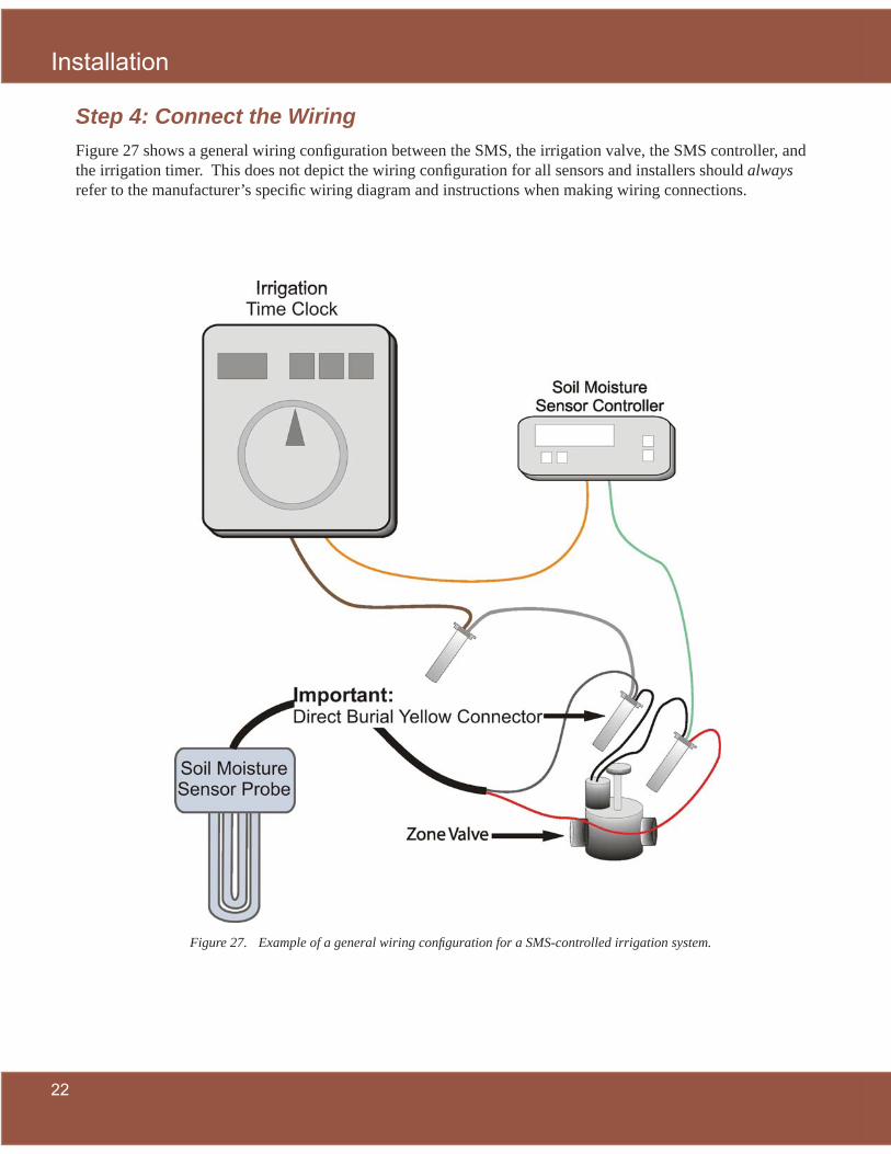
Step 4: Connect the WiringFigure 27 shows a general wiring confi guration between the SMS, the irrigation valve, the SMS controller, and the irrigation timer. This does not depict the wiring confi guration for all sensors and installers should always refer to the manufacturer’s specifi c wiring diagram and instructions when making wiring connections.
Example of a general wiring confi guration for a SMS-controlled irrigation system.Figure 27.

Installation
23
A. Connect Sensor to Zone ValveGenerally, sensors can be wired either to an irrigation valve or directly to the SMS controller. If possible, it is recommended that SMSs be wired to the nearest zone valve to facilitate sensor installation in the most representative area.
Wiring confi gurations vary among brands. Installers should always refer to specifi c wiring diagrams in the manufacturer’s installation manual. Figures 28 through 32 show a connection being made between a sensor and a zone valve.
Note: Direct burial yellow or red (DBY or DBR) connectors should be used on all connections between the sensor and the zone valve to prevent moisture intrusion and to provide a secure connection.
Uncover the irrigation zone Figure 29. valve box.
Disconnect the existing wiring Figure 30. connection between the irrigation timer and zone valve.
Prepare the soil moisture sensor Figure 31. and zone valve for connection.
Connect the wires from the soil Figure 32. moisture sensor to the zone valve.
Direct burial yellow Figure 28. (DBY) connector.
Enclose all wire nuts in direct Figure 33. burial connectors.

Installation
24
B. Connect SMS Controller to Irrigation TimerThe connections from the SMS controller to the irrigation timer also vary by brand and should always be done according to specifi cations in the manufacturer’s installation manual. Figures 33 through 36 show a Lawn Logic LL-1004 controller being wired to an irrigation time clock.
Connect SMS controller wiring to the irrigation Figure 36. timer wiring.
Power the SMS controller and the irrigation Figure 37. timer and check for proper functioning.
Open irrigation timer, exposing wires to be Figure 34. connected to SMS controller.
Install SMS controller adjacent to the irrigation Figure 35. timer on the side opposite the timer door hinges.

Calibration
25
III. CalibrationStep 1: Establish Controller Set-pointPrior to calibration and set-point establishment, it is necessary to determine how much water can be held in the root zone where the SMS is buried. To achieve this, the installer should saturate the area immediately around the SMS location. 24 hours after saturation, the controller will read a certain soil moisture content that will be close to fi eld capacity (i.e., no further water drainage below the root zone). Generally, the recommended soil moisture set-point is 75% of the fi eld capacity. Two primary methods for establishing fi eld capacity, bucket and irrigation, are recommended. A third method, calibration after a signifi cant rainfall, can be used in situations where rainfall occurs shortly after sensor installation.
Option 1. Bucket method•
Pour a 5 gallon bucketful of water directly 1. over the installed and connected SMS (Figure 37).
Wait 24 hours.2.
Perform the calibration according to the 3. manufacturer’s specifi cations.
Option 2. Irrigation method•
Specify a watering cycle period according 1. to Appendix B that will apply 1" of water to the zone where the sensor is installed.
Manually start the irrigation system for the 2. zone where the SMS is located by pressing the manual start button (Figure 38).
Wait 24 hours from the end of the irrigation cycle.3.
Perform the calibration according to the manufacturer’s 4. specifi cations.
Option 3. Post rainfall method•
Wait 24 hours from the end of a signifi cant rainfall event 1. (1" or more).
Perform the calibration according to the manufacturer’s 2. specifi cations.
Note: The soil surrounding the sensor should not receive any water during the 24-hour post-saturation period. If rainfall occurs during this period, then the soil will not be at fi eld capacity at the end of 24 hours and the procedure must be repeated once the soil dries.
Manual start of the irrigation Figure 39. time clock to saturate area around SMS for calibration.
Establishing the controller set-point—bucket Figure 38. method. Arrow points to sensor location.

Calibration
26
Step 2: CalibrationAlways refer to the manufacturer's specifi cations for detailed SMS controller calibration procedures. Calibration instructions are brand-specifi c and cannot be adequately specifi ed in general terms.
Timing with Plant EstablishmentIn new landscapes, plants (including turfgrass) are typically installed about the same time as irrigation systems. During establishment, plants have their highest water requirements as they develop their root system. The St. Johns River Water Management District irrigation rules state: “Irrigation of new landscape is allowed at any time of day on any day for the initial 30 days and every other day for the next 30 days for a total of one 60-day period, provided that the irrigation is limited to the minimum amount necessary for establishment” (SJRWMD).
Two SMS calibration issues arise during a plant establishment period. First, the irrigation system will be set to meet the water requirements of newly installed plants and the SMS controller will be turned off during this period. Second, plant root depth and soil qualities in the root zone will change signifi cantly during establishment. As a result, the controller should be calibrated post-establishment when the irrigation timer is reset for normal operation.
Manufacturer Recommended Set-PointsAlways refer to the manufacturer’s installation manual for specifi c set-point recommendations. Generally, a SMS controller should be set at an initial soil moisture set-point equivalent to 75% of fi eld capacity. Table 3 shows volumetric moisture content (VMC) settings for several fi eld capacity VMCs.
Table 3: Recommended SMS Controller Set-Points
Field Capacity 10% 15% 20% 25%
Moisture Setting (Threshold) 8% 11% 15% 19%

Calibration
27
Irrigation Time Clock SchedulingThe irrigation time clock, not the SMS controller, initiates scheduled irrigation events. It is extremely important that the irrigation time clock be set for an irrigation schedule appropriate for the irrigation system, location, plant need, season, and your water management district's requirements. Appendix B contains recommended irrigation scheduling for Florida turfgrasses. To establish the run time for a particular zone, use the following procedure:
Determine your region (e.g., Central Florida)1.
Determine the season (e.g., autumn)2.
For each zone, determine the appropriate application rate. (e.g., 0.5 in/hr for typical rotors, 1.5 in/hr for 3. typical spray heads) (See: Dukes and Haman, 2002a).
Determine the appropriate run time for each zone according to Appendix B (e.g., 85 minutes for a zone 4. with an application rate of 0.50 in/hr during autumn months).
Program the specifi c run time into the irrigation timer for each zone.5.
Repeat for each zone until all zones have been programmed appropriately.6.
Note: For additional assistance in setting you irrigation time clock see the Florida Automated Weather Network (FAWN) Urban Irrigation Scheduler at: http://fawn.ifas.ufl .edu/tools/urban_irrigation/

Calibration
28

Maintenance
29
IV. MaintenanceCurrently, SMS control system manufacturers do not specify routine maintenance procedures. A properly working SMS controller should not result in excessive irrigation application. If the system is applying excessive amounts of irrigation, it needs to be inspected by an irrigation contractor. The principle maintenance task described here is monitoring of the irrigation system’s functioning.
Note: As previously mentioned, to improve monitoring and maintenance of the SMS, the sensor location should be marked on an as-built design plan displayed next to the irrigation timer.
A. Evaluate Soil Moisture Sensor Functioning
Step 1: Review water bill/meterThe water bill should be reviewed to estimate how much water is being used for irrigation. For new homes, initial irrigation is likely to be higher for plant establishment, and water consumption should be compared with water use for a similar existing landscape. After extended occupancy, it will be possible to compare current water use with past water use. In existing homes, it is fairly straightforward to compare irrigation between pre and post-SMS installation conditions.
For a complete evaluation tool, the following should be known:
Amount of water used for irrigation as reported in the monthly utility bill.1.
Irrigated landscape area taken either from an irrigation plan or estimated based on the lot and house size.2.
a. Estimate monthly outdoor water use
Single Meter
If one meter combines monitoring of domestic indoor water use and outdoor irrigation water use, the two uses should be separated. Two methods can be used for this calculation.
Method 1. Assume the average Floridian uses 53 gallons per day indoors (Marella, 2004, p. 15). Multiply this by the number of people in the household to calculate indoor domestic water use.
Formula: 53 gallons /day × ____ people in household × ____ days in month = monthly indoor water use
Method 2. Calculate the monthly domestic indoor use based on the water bill during a period of low net irrigation requirement (winter months). If the irrigation timer is set properly, irrigation during those winter months should be near zero, and total consumption can act as a baseline for monthly domestic indoor water consumption throughout the year. To determine monthly outdoor water use subtract the monthly indoor use from the monthly total water use.
Formula: ____ total monthly water use -____ monthly indoor use = ____ monthly outdoor use

Maintenance
30 3
Dual Meter
If an independent water meter is installed to record irrigation consumption, calculating SMS performance is relatively straightforward. The only required calculation is estimation of the irrigated landscape area (ft2).
b. Compare to Appendix C
Appendix C contains monthly recommended net irrigation volume in gallons by region. Net irrigation is calculated by subtracting average rainfall from historical evapotranspiration (ET). To compare your monthly irrigation application to the net irrigation requirements in Appendix C, take the following steps:
Determine your region (e.g., Central Florida). 1.
Determine the season (e.g., autumn). 2.
Estimate your irrigated landscape area in square feet (e.g., 2,000 ft3. 2).
Find the recommended net irrigation volume in gallons from Appendix C based on steps 1-3 (e.g., 4,300 4. gallons)
Compare this recommendation to the amount of monthly outdoor water use from your utility bill (e.g., 5. 4,000 gallons). Be careful that the amount of water from your bill is one month as some utilities bill on a bimonthly basis.
If you are applying excessive amounts of irrigation volume compared to the recommended net irrigation 6. volume, the SMS control system should be inspected by an irrigation contractor. (In this example, irrigation volume is reasonable. Check again the following month.)
Step 2: Manual StartAnother method for monitoring the SMS controller function is a manual start of the irrigation time clock. This is done by pressing the irrigation time clock’s manual start button when irrigation is unnecessary (the SMS controller is in bypass mode). When the manual start is pressed, the irrigation system should not come on. If a watering cycle is activated under these conditions, there is a problem with the system’s functioning and an irrigation contractor should be contacted (Figure 39).
Manual start of irrigation timer while Figure 40. SMS controller is “On Hold” to test proper operation.
Maintenance
31
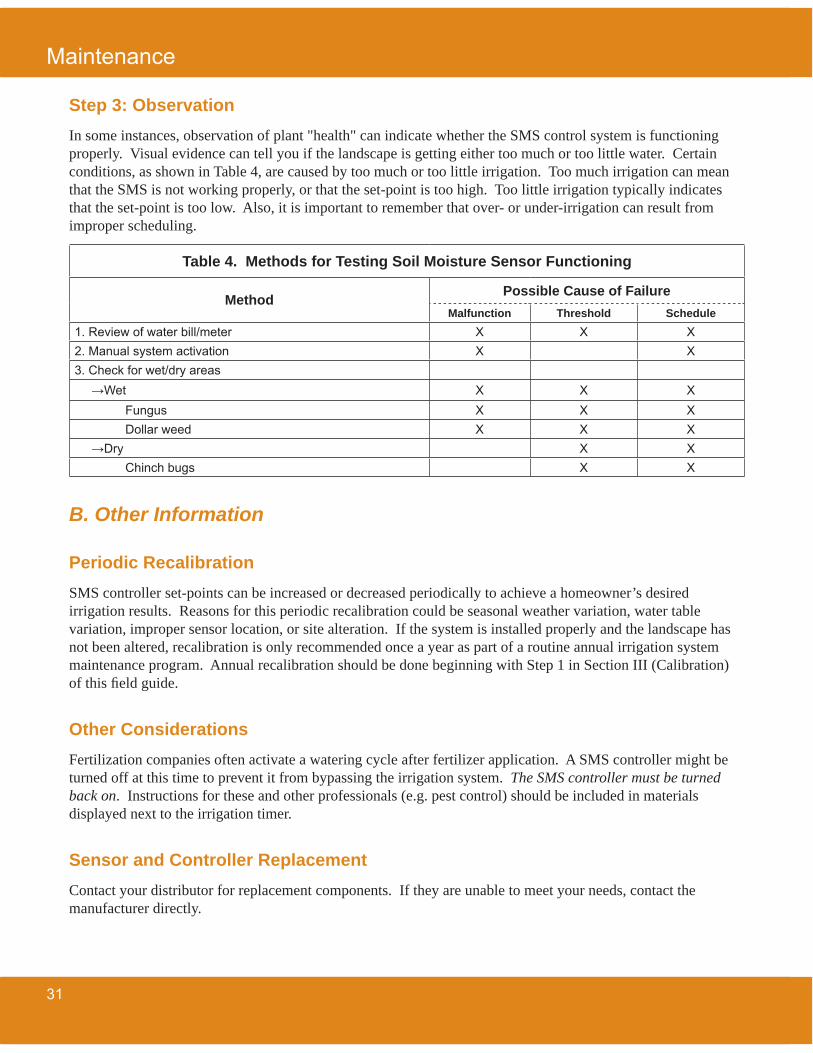
Step 3: ObservationIn some instances, observation of plant "health" can indicate whether the SMS control system is functioning properly. Visual evidence can tell you if the landscape is getting either too much or too little water. Certain conditions, as shown in Table 4, are caused by too much or too little irrigation. Too much irrigation can mean that the SMS is not working properly, or that the set-point is too high. Too little irrigation typically indicates that the set-point is too low. Also, it is important to remember that over- or under-irrigation can result from improper scheduling.
B. Other Information
Periodic RecalibrationSMS controller set-points can be increased or decreased periodically to achieve a homeowner’s desired irrigation results. Reasons for this periodic recalibration could be seasonal weather variation, water table variation, improper sensor location, or site alteration. If the system is installed properly and the landscape has not been altered, recalibration is only recommended once a year as part of a routine annual irrigation system maintenance program. Annual recalibration should be done beginning with Step 1 in Section III (Calibration) of this fi eld guide.
Other ConsiderationsFertilization companies often activate a watering cycle after fertilizer application. A SMS controller might be turned off at this time to prevent it from bypassing the irrigation system. The SMS controller must be turned back on. Instructions for these and other professionals (e.g. pest control) should be included in materials displayed next to the irrigation timer.
Sensor and Controller ReplacementContact your distributor for replacement components. If they are unable to meet your needs, contact the manufacturer directly.
Table 4. Methods for Testing Soil Moisture Sensor Functioning
Method Possible Cause of FailureMalfunction Threshold Schedule
1. Review of water bill/meter X X X2. Manual system activation X X3. Check for wet/dry areas
→Wet X X XFungus X X XDollar weed X X X
→Dry X XChinch bugs X X

Maintenance
32

Troubleshooting
33
V. TroubleshootingA. SMS control systems have troubleshooting procedures that are typically model-specifi c, and operators should always refer to the manufacturer’s installation manual for troubleshooting guidance.
Important RemindersBe certain that the sensor is connected to the valve controlling irrigation in the sensor’s location.•
Make sure the correct wire is connected to the sensor zone terminal on the irrigation timer.•
Make sure all in-ground wiring connections are enclosed within a direct burial connector.• Make sure the circuit connecting the sensor, zone valve, SMS controller, and time clock is properly con-• nected (i.e. no short circuit).

Troubleshooting
34

Resources
35
VI. References and ResourcesA. Irrigation SchedulingAugustin, B. J. (2000). Water Requirements of Florida Turfgrasses. BUL200, Institute of Food and Agricul-
tural Sciences, University of Florida, Gainesville, FL. Available: http://edis.ifas.ufl .edu/pdffi les/EP/EP02400.pdf
Dukes, M. D. and Haman, D. Z. (2002a). Operation of residential irrigation controllers. CIR1421, Institute of Food and Agricultural Sciences, University of Florida, Gainesville, FL. Available: http://edis.ifas.ufl .edu/AE220
Florida Automated Weather Network (FAWN) Urban Irrigation Scheduler. http://fawn.ifas.ufl .edu/tools/urban_irrigation/
St. Johns River Water Management District. (2006). Summary of Lawn and Landscape Irrigation Rule and Ex-ceptions. Available: http://www.sjrwmd.com/programs/outreach/conservation/irrigation_rule/index.html
B. General Irrigation Dukes, M. D. and Haman, D. Z. (2002b). Residential irrigation system rainfall shutoff devices. ABE325, Insti-
tute of Food and Agricultural Sciences, University of Florida, Gainesville, Fla. Available: http://edis.ifas.ufl .edu/AE221
Haley, M. B., M. D. Dukes, and G. L. Miller. (2007). Residential irrigation water use in Central Florida. Jour-nal of Irrigation and Drainage Engineering 133(2), 427–434.
C. UF Soil Moisture Sensor ResearchCardenas-Lailhacar, B., M. D. Dukes, and G. L. Miller. (in press). Sensor-based automation of irrigation on
bermudagrass, during wet weather conditions. Journal of Irrigation and Drainage Engineering.
Dukes, M. D., B. Cardenas-Lailhacar, G. L. Miller. (2005). Residential Irrigation Based on Soil Moisture. Resource June/July, 4–6.
Dukes, M. D., B. Cardenas-Lailhacar, S. Davis, M. B. Haley, M. Shedd. (2007). Smart Water Application Technology (SWAT) Evaluation in Florida. Proceedings of the American Society of Agricultural and Biological Engineers (ASABE) Annual International Meeting, 2007. Minneapolis, Minnesota.
Haley, M, and M. D. Dukes. (2007). Evaluation of sensor-based residential irrigation water application. ASA-BE 2007 Annual International Meeting, Minneapolis, Minnesota, 2007. ASABE Paper No. 072251.
Shedd, M., M. D. Dukes, and G. L. Miller. (2007). Evaluation of evapotranspiration and soil moisture-based irrigation control on turfgrass. Proceedings of the ASCE EWRI 2007 World Environmental & Water Resources Congress 2007. Tampa, Fla.

Resources
36
D. Water Effi ciencyFlorida Water Star. http://sjr.state.fl .us/programs/outreach/conservation/water_star/water_star.html
Marella, R.L. (2004). Water withdrawals, use, discharge, and trends in Florida, 2000. U.S. Geological Survey Scientifi c Investigations Report 2004-5151.

Appendix
37
VII. Appendices
Appendix A: Where to Install a Soil Moisture Sensor (SMS)
Prerequisites for Placement:Within the root zone of turfgrass• In sunniest area possible• Within the driest area possible considering all other factors• Within the center of an irrigation zone•
Main Areas to Avoid: Minimum Distance AwayAway from structures (house, garage, shed, etc.)• 5 ftAway from a property line• 5 ftAway from depressions/swales• 5 ftAway from impervious surfaces• 5 ftAway from plant beds• 3 ft
High Moisture Areas to Avoid:Away from an overhang• 5 ftAway from an air conditioner condensate line• 5 ftAway from a hose bib• 5 ftAway from north (shaded) side of the home• 5 ftAway from tree canopy• 5 ftAway from a downspout• 5 ft
Disturbed Areas to Avoid:Away from construction roads• 4 ftAway from areas with plant debris (i.e., tree stump)• 3 ftAway from areas with fi ll dirt• 3 ft
Away from buried materials• 2 ft

Appendix
38
Appendix B: Irrigation scheduling per irrigation event for Florida turfgrasses (min)
Season North Central South Season North Central South
0.50 in/hr 1.50 in/hr
Winter 5 25 50 Winter 0 10 15Spring 75 110 80 Spring 25 35 25Summer 80 95 100 Summer 25 30 35
Autumn 55 85 65 Autumn 20 30 20
0.75 in/hr 1.75 in/hr
Winter 0 15 35 Winter 0 5 15Spring 50 70 55 Spring 20 30 25
Summer 55 65 65 Summer 25 25 30
Autumn 40 55 45 Autumn 15 25 20
1.00 in/hr 2.00 in/hr
Winter 0 15 25 Winter 0 5 15Spring 40 55 40 Spring 20 25 20Summer 40 45 50 Summer 20 25 25Autumn 30 45 35 Autumn 15 20 15
1.25 in/hr Season = Month w/ highest net requirement
Winter 0 10 20
Spring 30 44 30
Summer 35 40 40
Autumn 25 35 25
Events occur twice per week• 60% system effi ciency• Calculated from historical ET and effective rainfall• Numbers rounded for convenience•
Adapted from: Augustin, 2000; and Dukes and Haman, 2002a

Appendix
39
Appendix C: Monthly Net Irrigation Requirements for Florida
Table 1: Monthly Net Irrigation Requirements for North Florida
Net Irrigation Requirement (Historical ET - Rainfall)
Volume (gallons) of Irrigation per Irrigated Area (sq. ft.)
Season Application (Inches)
Irrigated Area (sq. ft.)
2,000 4,000 6,000 8,000 10,000
Spring 3.70 4,600 9,200 13,800 18,500 23,000
Summer 3.21 4,000 8,000 12,000 16,000 20,000
Autumn 3.51 4,400 8,800 13,100 17,500 21,900
Winter 1.44 1,800 3,600 5,400 7,200 9,000
Annual Total 11.86 14,800 29,600 43,300 59,200 73,900
Requirements are for Gainesville, FL• Seasons are the months with the highest irrigation requirement• Spring = May• Summer = June• Autumn = September• Winter = December•
Adapted from Augustin, 2000
Table 2: Monthly Net Irrigation Requirements for Central Florida
Net Irrigation Requirement (Historical ET - Rainfall)
Volume (gallons) of Irrigation per Irrigated Area (sq. ft.)
Season Application (Inches)
Irrigated Area (sq. ft.)
2,000 4,000 6,000 8,000 10,000
Spring 4.73 5,900 11,800 17,700 23,600 29,500
Summer 4.68 5,800 11,700 17,500 23,300 29,200
Autumn 3.41 4,300 8,500 12,800 17,000 21,300
Winter 1.19 1,500 3,000 4,500 6,000 7,400
Annual Total 14.01 17,500 35,000 52,500 69,900 87,400
Requirements are for Orlando, FL• Seasons are the months with the highest net irrigation requirement.• Spring = May• Summer = August• Autumn = September• Winter = November•
Adapted from Augustin, 2000

Appendix
40
Table 3: Monthly Net Irrigation Requirements for South Florida
Net Irrigation Requirement (Historical ET - Rainfall)
Volume (gallons) of Irrigation per Irrigated Area (sq. ft.)
Season Application (Inches)
Irrigated Area (sq. ft.)
2,000 4,000 6,000 8,000 10,000
Spring 4.12 5,100 10,300 15,400 20,500 25,700
Summer 4.06 5,100 10,100 15,200 20,200 25,300
Autumn 2.96 3,700 7,400 11,100 14,800 18,500
Winter 2.07 2,600 5,200 7,700 10,300 12,900
Annual Total 13.21 16,500 33,000 49,400 65,800 82,400
Requirements are for Ft. Myers, FL• Seasons are the months with the highest irrigation requirement• Spring = May• Summer = August• Autumn = November• Winter = December•
Adapted from Augustin, 2000


