Solidification / microsegregation model applied to ...
52
METRO MEtallurgical TRaining On-line Education and Culture Solidification / microsegregation model applied to description of diffusion soldering / brazing Waldemar Wołczyński IMMS PAS
Transcript of Solidification / microsegregation model applied to ...
METRO MEtallurgical TRaining On-line
Education and Culture
Solidification / microsegregation model applied to description of
diffusion soldering / brazing
Waldemar WołczyńskiIMMS PAS

2METRO – MEtallurgical TRaining On-line Copyright © 2005 Waldemar Wołczyński - IMMS PAS
Non-equilibrium solidificationScheil’s theory
Scheil’s theory for the non-equilibrium solidification / microsegregation
( ) ( ) 10 10; −−= k
L xNxNsolute concentration in the liquid
( ) ( ) 10 10, −−= k
S xkNxNsolute concentration at s/l interface
( ) ( ) 10 10, −−= k
B xkNxNsolute redistribution in the solid
redistribution is a result of back-diffusion, but no diffusion in the solidaccording to the Scheil’s model, thus α = 0, and NB(x,0) = NS(x,0)
E. Scheil, Zeitschrift fur Metallkunde, 34, (1942), 70-80
3METRO – MEtallurgical TRaining On-line Copyright © 2005 Waldemar Wołczyński - IMMS PAS
Non-equilibrium solidificationMulti-peritectic systems
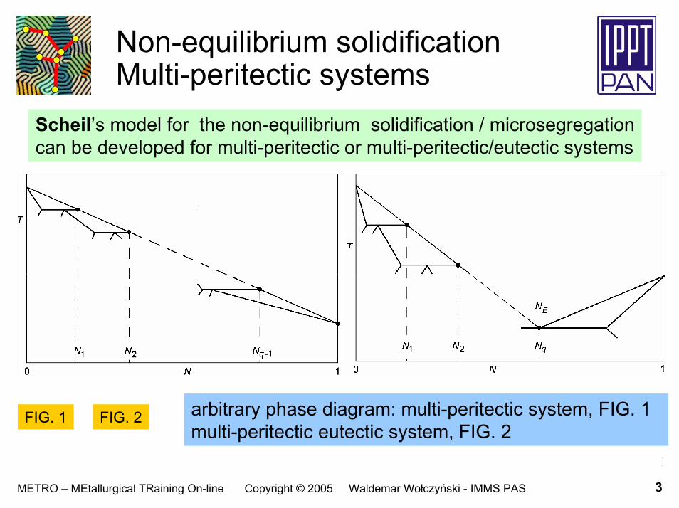
Scheil’s model for the non-equilibrium solidification / microsegregationcan be developed for multi-peritectic or multi-peritectic/eutectic systems
arbitrary phase diagram: multi-peritectic system, FIG. 1 multi-peritectic eutectic system, FIG. 2
FIG. 1 FIG. 2

4METRO – MEtallurgical TRaining On-line Copyright © 2005 Waldemar Wołczyński - IMMS PAS
Non-equilibrium solidificationSolute behaviour
Scheil’s model for the non-equilibrium solidification / microsegregationis now developed for multi-peritectic or multi-peritectic eutectic systems
( )1
11 1
10;−
−− ⎟⎟
⎠
⎞⎜⎜⎝
⎛−−
=ik
iiL x
xNxNsolute concentration in the liquid
( )1
11 1
10;−
−− ⎟⎟
⎠
⎞⎜⎜⎝
⎛−−
=ik
iiiS x
xNkxNsolute concentration at s/l interface
( )1
11 1
10;−
−− ⎟⎟
⎠
⎞⎜⎜⎝
⎛−−
=ik
iiiB x
xNkxNsolute redistribution in the solid
x [ ]ii xxx ,1−∈amount of the growing solid, dimensionless qi ,...,1=

5METRO – MEtallurgical TRaining On-line Copyright © 2005 Waldemar Wołczyński - IMMS PAS
Non-equilibrium solidificationInitial conditions
Scheil’s model for the non-equilibrium solidification / microsegregationis now developed for multi-peritectic or multi-peritectic eutectic systems
( ) ( )xkxN
dxxdN
LL
−−
=110,
0,
travelling initialconditionN0(x0), N1(x1) …is applied to abovedifferential equation FIG. 3
W.Wołczyński, Chapter 2 in: Modelling of Transport Phenomena in Crystal Growth, eds. J.Szmyd & K.Suzuki, ed. WIT Press, Southampton, Boston, (2000), p. 19-59

6METRO – MEtallurgical TRaining On-line Copyright © 2005 Waldemar Wołczyński - IMMS PAS
Non-equilibrium solidificationAmount of the solid
Scheil’s model for the non-equilibrium solidification / microsegregationis now developed for multi-peritectic or multi-peritectic eutectic systems
( ) ( ) ( )∏−
=
−+−
−−−−=
1
1
11
11
1
11
111
01i
j
jkjkjikiki NNNx qi ,...,2=
( )( )0;
0;xNxN
kL
S= partition ratio for q = 1
ik partition ratio, generallyqi ,...,1=
qi ,...,1=ix amount of the primary solid at a given peritectic reaction

7METRO – MEtallurgical TRaining On-line Copyright © 2005 Waldemar Wołczyński - IMMS PAS
Equilibrium solidification
( ) ( ) 10 11; −−+= xkxNxNLsolute concentration in the liquid
( ) ( ) 10 11; −−+= xkxkNxNSsolute concentration at s/l interface
( ) 01;1 NNB =solute redistribution in the solid
a general description of solidification/microsegregation is required !

8METRO – MEtallurgical TRaining On-line Copyright © 2005 Waldemar Wołczyński - IMMS PAS
General theory forsolidification / microsegregationBrody-Flemings theory
a general theory has already been proposed by Brody and Flemings, but according to the theory, back-diffusion parameter tends to infinity: αmoreover, no description for the solute redistribution in the solid is givenand mass balance is not satisfied
∞
however, back-diffusion parameter should tend to unity: α 1
2LtD fS=α
d
f
tt
=αS
d DLt
2
=with
really, when tf = td then α = 1,
tf local solidification time, td time necessary for homogenization
RESULT a general description of solidification/microsegregation is always required !

9METRO – MEtallurgical TRaining On-line Copyright © 2005 Waldemar Wołczyński - IMMS PAS
General theory for solidification / microsegregation
( ) ( ) kk
L xkxNxN ααα −−
−+= 11
0 1;solute concentration in the liquid
( ) ( ) kk
S xkxkNxN ααα −−
−+= 11
0 1;solute concentration at s/l interface
( ) ( ) ( ) ( ) ( )ααββαα ;,;;,; 000 xNxxxxNxxN LinexSB +=solute redistribution in the solid
10 ≤≤ α[ ]Kxx ,00 ∈[ ]Kxx ,0∈ ( ) ( ) ( )αββαβ ,;,; 000 xxxxx inex=
0x ≡parameter representing freezing amount of the solid when solidification is arrested
W.Wołczyński, Chapter 2 in: Modelling of Transport Phenomena in Crystal Growth, eds. J.Szmyd & K.Suzuki, ed. WIT Press, Southampton, Boston, (2000), p. 19-59

10METRO – MEtallurgical TRaining On-line Copyright © 2005 Waldemar Wołczyński - IMMS PAS
Generalization
proposed equations are reducible to: Scheil’s equations for α = 0and description of equilibrium solidification for α = 1
( ) ( )ααβ ,;,; KBKS xxNxxN ≡
( )0
11
NNk EkE
k
E =−−
ααFIG. 4
schematic view of soluteredistribution for four representative valuesof back-diffusion parameter

11METRO – MEtallurgical TRaining On-line Copyright © 2005 Waldemar Wołczyński - IMMS PAS
Diffusion soldering / brazing Phenomena
# dissolution# solidification# solid / solid transformations
#dissolution prepares initial solution within zone, dxfor solidification#solidification forms sub-layers within the solder/braze#solid/solid transformations usually occur after completion of both phenomena: dissolution + solidification
• solute concentration of the initial solution is equal to: N0 • zone dx is formed by dissolution just at the surface of a
substrate, perpetually • next, solidification of a given zone dx, is expected• some reactions occur during solidification !!!

12METRO – MEtallurgical TRaining On-line Copyright © 2005 Waldemar Wołczyński - IMMS PAS
Solid / liquid interface
2D solidificationformation of cellular morphology
FIG. 5
x current amount of the growing solid (layer) 0 < x < xKX0 amount of solid (layer) for which solidification is stopped and morphology frozen xK amount of solid (layer) just before precipitation of the so-called
last droplet of the liquid (eutectic)
13METRO – MEtallurgical TRaining On-line Copyright © 2005 Waldemar Wołczyński - IMMS PAS
Distance
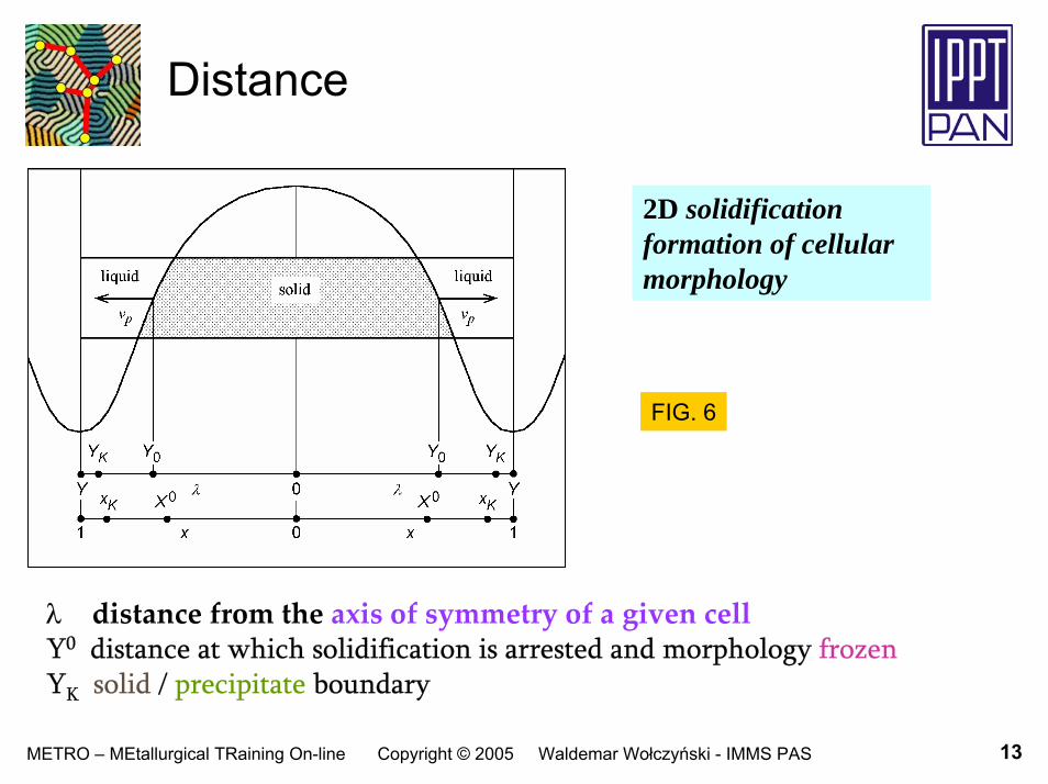
2D solidificationformation of cellular morphology
FIG. 6
λ distance from the axis of symmetry of a given cellY0 distance at which solidification is arrested and morphology frozen YK solid / precipitate boundary

14METRO – MEtallurgical TRaining On-line Copyright © 2005 Waldemar Wołczyński - IMMS PAS
Application of 2D modelto 1D model of multi-layer formation
FIG. 8
FIG. 7
2D solidificationformation of cellular morphology
λ distance from the substrate surfaceX0 =1 amount of multi-layer at which solidification
is stopped and morphology frozen tF time of the completion of solidification 1D solidification leading
to formation multi-layer

15METRO – MEtallurgical TRaining On-line Copyright © 2005 Waldemar Wołczyński - IMMS PAS
X0, L0 Model 2D
amount of the arrested solid within i - range ofsolidification, during diffusion soldering/brazing
⎪⎩
⎪⎨
⎧
=∑−
== −
=;,...,2,
;1,1
1
0
0
0nixX
iXx i
j
maxj
i
⎪⎩
⎪⎨
⎧
=∑−
== −
=;,...,2,
;1,1
1
0
0
0nixL
iLl i
j
maxj
i
amount of the liquid at a beginning of i - range of solidification, during diffusion soldering/brazing
a peritectic reaction occurs at the end of a given range,according to a model referred to phase diagram for stable equilibrium

16METRO – MEtallurgical TRaining On-line Copyright © 2005 Waldemar Wołczyński - IMMS PAS
Fundamentals of the „zone dx” - model
dissolution leads to ensure N0 solute concentration within each dx
dissolution path: NF N0
solidification occurs within each dxsolidification path:
N0 NF
CONCLUSIONS:
no freezing is possible for fraction dx !
- therefore X0 = 1, for each dx- when solidification is arrested,
X0 = 1, for the sum of all dx solidified before arresting
• the diffusion soldering occurs at a constant temperature, TR
• the liquid solution NF
is not undercooled• the liquid solution N0
is strongly undercooled
CONCLUSION !• peritectic reactions
are undercooledperitectic reactions !
17METRO – MEtallurgical TRaining On-line Copyright © 2005 Waldemar Wołczyński - IMMS PAS
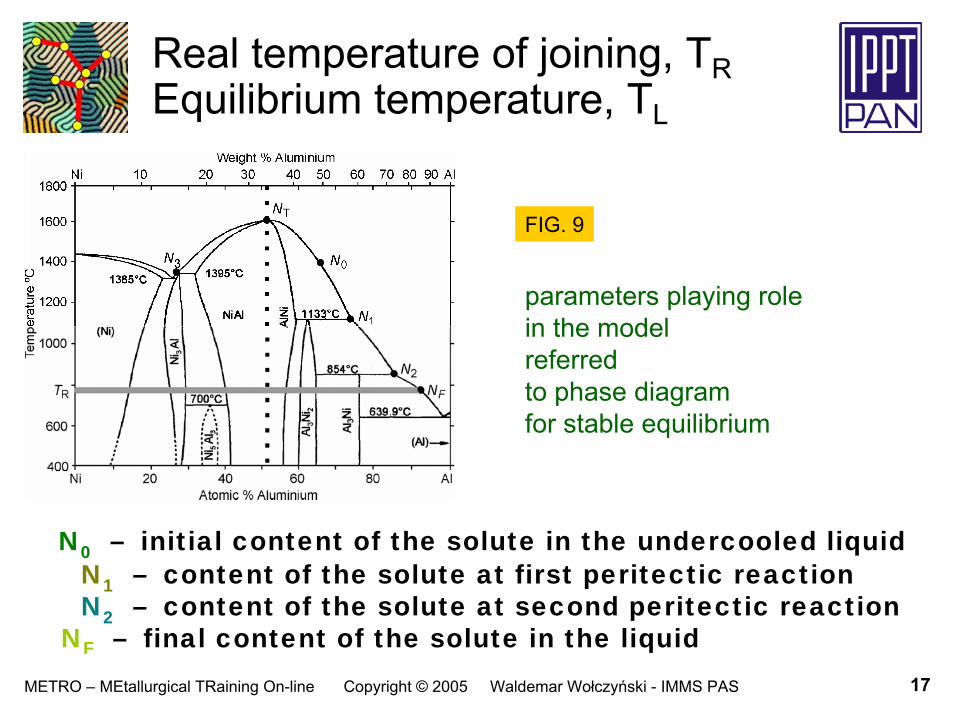
Real temperature of joining, TREquilibrium temperature, TL
FIG. 9
parameters playing rolein the model referred to phase diagramfor stable equilibrium
N0 – initial content of the solute in the undercooled liquidN1 – content of the solute at first peritectic reactionN2 – content of the solute at second peritectic reaction
NF – final content of the solute in the liquid

18METRO – MEtallurgical TRaining On-line Copyright © 2005 Waldemar Wołczyński - IMMS PAS
Driving force for solidification Model Stable equilibrium
FIG. 10
driving force according tothe model based on stable equilibrium
∆Τ = TL – TR = T(NL) - TR
at the NF - solute content in the liquidsolidification process is completedand: ∆Τ =0
scheme valid for each zone dxcreated during solidification

19METRO – MEtallurgical TRaining On-line Copyright © 2005 Waldemar Wołczyński - IMMS PAS
Initial transient stable formation of the phases
FIG. 11
at time t32S/M stable solidification
transforms into metastable process
dx is just formed and initialtransient solidification begins
• Al-liquid filler metal starts to be melted: Al (s) Al
• solidification (or birth)of first primary phase AlNiis to be expected at t11
B = 0
• at time t32B the Al3Ni2 birth
takes place and stable AlNi phase transforms continuously into the Al3Ni2dominant phase
initialtransientperiodof process
20METRO – MEtallurgical TRaining On-line Copyright © 2005 Waldemar Wołczyński - IMMS PAS
Competition
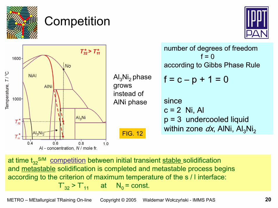
number of degrees of freedom f = 0
according to Gibbs Phase Rule
f = c – p + 1 = 0
sincec = 2 Ni, Alp = 3 undercooled liquidwithin zone dx, AlNi, Al3Ni2
Al3Ni2 phase growsinstead ofAlNi phase
FIG. 12
at time t32S/M competition between initial transient stable solidification
and metastable solidification is completed and metastable process begins according to the criterion of maximum temperature of the s / l interface:
T*32 > T*
11 at N0 = const.

21METRO – MEtallurgical TRaining On-line Copyright © 2005 Waldemar Wołczyński - IMMS PAS
Filler metal transformation
FIG. 13 FIG. 14
scheme of thetransformation
definition of NF
liquid (N1) remains after solidification of the dominant Al3Ni2 phase
f = c – p + 1 = 0sincec = 2 Ni, Alp = 3 dx, Al3Ni2, NF
TRANSFORMATION:
liquid (N1) + Al liquid (NF )

22METRO – MEtallurgical TRaining On-line Copyright © 2005 Waldemar Wołczyński - IMMS PAS
Birth of coupled phase
FIG. 15 number of degrees of freedom f = 0
according to Gibbs Phase Rule
f = c – p + 1 = 0
since
c = 2 Ni, Alp = 3 undercooled liquid within
the zone dx, ( N0 ),Al3Ni2 and Al3Ni
scheme of the coupled phase birth
first peritectic phasethat is, dominant phasehas already its height equal to h32
at time t31B the birth of Al3Ni phase is observed

23METRO – MEtallurgical TRaining On-line Copyright © 2005 Waldemar Wołczyński - IMMS PAS
Birth of coupled phaseExperimental confirmation
FIG. 16
birth of the coupled phase Al3Ni on the surface ofdominant phase Al3Ni2as observed experimentally
solidification is faster or slower;it depends on the local orientation
by courtesy of Dr J. Janczak-Rusch, EMPA, Dübendorf, Switzerland

24METRO – MEtallurgical TRaining On-line Copyright © 2005 Waldemar Wołczyński - IMMS PAS
Birth of coupled phaseExperimental confirmation
FIG. 17
birth of the coupled phase ζon the surface of dominant phase δas observed experimentally
solidification is faster or slower;it depends on the local orientation
by courtesy of Prof. E.Guzik and Dr D. Kopyciński,University of Science and Technology,
Kraków, Poland

25METRO – MEtallurgical TRaining On-line Copyright © 2005 Waldemar Wołczyński - IMMS PAS
Perpetual formation of zone, dxby the liquid, NF
zone dx is formed just at the surface of substrate
the liquid NF reacted with substrate Niso long as zone, dx, becomes liquidthe reaction leads to creation of the solute concentration equal to the N0the value of the N0 depends on the real temperature, TR,imposed by technology
cellular morphology of sub-layers
liquid (NF) + substrate (Ni) undercooled liquid (N0)
the liquid (NF) diffuses along the channels between cellsFIG. 18

26METRO – MEtallurgical TRaining On-line Copyright © 2005 Waldemar Wołczyński - IMMS PAS
Undercooled peritectic reactionsMetastable conditions
undercooled liquid (N0) diffuses alonginternal channels towards the solid/liquid interface of cells dominant phase solidifies due to firstundercooled peritectic reactioncoupled phase solidifies due to secondundercooled peritectic reaction
solidification is completed at time, tS
at time, tM,first solid / solid transformation takes place
FIG. 19 undercooled peritectic reaction under metastable conditionscan also be described by reaction resulting from phase diagramfor stable equilibrium: primary phase + liquid peritectic phase
peritectic reactions

27METRO – MEtallurgical TRaining On-line Copyright © 2005 Waldemar Wołczyński - IMMS PAS
Undercooled peritectic reactionsMetastable conditions
undercooled liquid (N0) diffuses alonginternal channels towards the solid/liquid interface of cells
peritectic reactionsFe/Zn/Fe joint
FIG. 20
undercooled peritectic reaction under metastable conditionscan also be described by reaction resulting from phase diagramfor stable equilibrium: primary phase + liquid peritectic phase

28METRO – MEtallurgical TRaining On-line Copyright © 2005 Waldemar Wołczyński - IMMS PAS
Completion of solidification
FIG. 21• no more zone dx• ss zone remains• s zone remains• both sub-layers
are fully formed• N0 concentration
is conserved dueto mass balance
• channels still existinternal & external
• no more NF - liquid
each sub-layerconsists of cells
CONCLUSION: time tS depends on thickness of foil applied for joining

29METRO – MEtallurgical TRaining On-line Copyright © 2005 Waldemar Wołczyński - IMMS PAS
Operating range for solidification
operating range
model referredto phase diagramfor stable equilibrium
FIG. 22
formation of Al3Ni2–Al3Ni multi-layer on Ni - substrate formation of multi-layer follows mechanism of undercooled peritectic reactions at TR technological temperature according to phase diagram for stable equilibrium:primary (AlNi) + liquid (N1) Al3Ni2primary (Al3Ni2) + liquid (N2) Al3Ni

30METRO – MEtallurgical TRaining On-line Copyright © 2005 Waldemar Wołczyński - IMMS PAS
Solidification path
Ni-Al phase diagram
FIG. 24
Fe-Zn phase diagramFIG. 23
reduced N0 N1 N2 and full N0 N1 N2 NF solidification path; reduced k1N0 k1N1 k2N1 k2N2 and full k1N0 k1N1 k2N1 k2N2 k3N2 k3NF
historical, NS, s/l interface path Ni/Al/Ni
a peritectic reaction occurs at the end of a given solidification range

31METRO – MEtallurgical TRaining On-line Copyright © 2005 Waldemar Wołczyński - IMMS PAS
Redistribution coefficient, β
arbitrary phase diagram
NL
solute concentrationin the liquidNS
solute concentration at the s/l interfaceNB
solute redistribution after back diffusion
FIG. 25

32METRO – MEtallurgical TRaining On-line Copyright © 2005 Waldemar Wołczyński - IMMS PAS
Back-diffusion parameter, α
back-diffusion parameterarbitrary phase diagram
FIG. 26
αD = 0 axis corresponding to the Scheil’s theoryαD > 0 axis corresponding to the general model
for solidification / microsegregation

33METRO – MEtallurgical TRaining On-line Copyright © 2005 Waldemar Wołczyński - IMMS PAS
Equations
Li
iLii
Lii
NNkkNk 10)( −+= universal definition of partition ratio
( ) [ ]minmaxiiii xxNliquidx −⇒+ amount of peritectic phase due to
reaction resulting from phase diagram
[ ] [ ( ) ]11
110
10 11),,,,( −
−
−−
− −−= ikikD
iiii
Diiiiii
Dii NNklkNNlx
ααα
amount of primary phase
xxklNkNk
xdNd
iDii
iLi
Lii
Li
−+
−−= −
001
0)1(α
differential equation governingsolidification / microsegregation
10
10 ),,,,0( −− = iiii
Di
Li NkNlN α initial condition

34METRO – MEtallurgical TRaining On-line Copyright © 2005 Waldemar Wołczyński - IMMS PAS
Equations
( ) [ ]⎪⎭
⎪⎬⎫
−+−−+⎪⎩
⎪⎨⎧
−=
−
−
−−
01
10
000001
10 )()1(
1,,,, ikD
i
ik
iiDii
Lii
Li
i
iiii
Di
Li lxxklkkk
kNkNlxN ααα
( ) 1100
10 ,,,,),,,,( −−− += i
Liiii
Di
Liiiii
Di
Si NkkNlxNkkNlxN αα
( ) [ ] ),,,,(),,,(),,,(1,,,,, 01
000000001
00iii
Di
Siii
Dii
iniiii
exiiii
Dii
Bi kNlxNklxklxxkNlxxN −− += ααββα
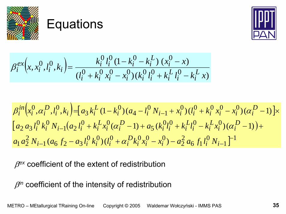
35METRO – MEtallurgical TRaining On-line Copyright © 2005 Waldemar Wołczyński - IMMS PAS
Equations
( ))()(
)()1(,,, 0000000
000000
xklklkxxklxxkklkklxx L
iiLiiiiiii
iLiiii
iiiexi
−+−+
−−−=β
( ) [ ][ ( )
] 11
016
22
0000003261
221
00005
0021
0032
000001
04
03
00
)()(
)1()()1(
)1()()()1(,,,
−−−
−
−
−−+−
+−−++−+
×−−++−−=
iiiiiDiiiii
Dii
Lii
Liii
Dii
Liiiii
Diiiiiiiii
Liii
Dii
ini
NlfaaxxklklafaNaa
xklklkaxklaNklaa
xxklxNlakkaklx
α
αα
ααβ
βex coefficient of the extent of redistribution
βin coefficient of the intensity of redistribution

36METRO – MEtallurgical TRaining On-line Copyright © 2005 Waldemar Wołczyński - IMMS PAS
Equations
∑=++
++++=
∞
=0
212 !)(
)()()1(!2
)1()1(!1
1),,,(k k
kkkkc
xbacc
xbbaacxbaxcbaF L
⎟⎟⎠
⎞⎜⎜⎝
⎛
−+−
−−
−
−=
)1(;
112;1,
1 000
00
0
00121 L
iDii
Dii
Li
iDi
iiDi
iDi
iiDi
kkkk
kkk
kkkFf
αααα
αα
⎟⎟
⎠
⎞
⎜⎜
⎝
⎛
−+
−+
−
−−
−
−=
)1(
)(;
1
12;1,
1 000
0000
0
00
0
00
122 Li
Dii
Diii
iiiDii
Li
iDi
iiDi
iDi
iiDi
kklk
xxklk
k
kk
k
kkFf
αα
α
α
α
α
α

37METRO – MEtallurgical TRaining On-line Copyright © 2005 Waldemar Wołczyński - IMMS PAS
Equations
[ ] 01
10
000001 )( ikD
i
ik
iiiiDii lxxkla αα −
−
−+=10
2 −+= Lii kka
021
001
41
)()(
i
Liiii
kaakxlNa
−
−−= −10
3 −+= Di
Li
Dii kka αα
000
00005 ln
iLiii
iLii
Liii
lklkxklklka
+
−+= )1()( 00000
6 −−+= iDii
Lii
Liii kxklklka α

38METRO – MEtallurgical TRaining On-line Copyright © 2005 Waldemar Wołczyński - IMMS PAS
Equations
0=Likfor
[ ]),,,,(),,,,,,,(
)(),,,,,(
);,,,,,,,(),,,,,,,(
01
001
01
00
01
01
01
0
01
01
0001
01
00
iiiiDiiiiiii
Pi
Dii
memi
iiiiiiiiDii
iiiiiPi
Dii
memiiiiii
Pi
Dii
maxi
kNNlxkkNNlxx
NkNkkNNlrwhen
kkNNlxxkkNNlxx
−+−
++−
+−+−
−
×−>
=
ααα
α
αααα
with
∫−= −−++−ix
iiiDii
Biiiii
Diiiiiiiii
Dii dxkNlxxNkNNlxNkkkNNlr
0
01
001
001
01
01
0 ),,,,,(),,,,(),,,,,( ααα
and
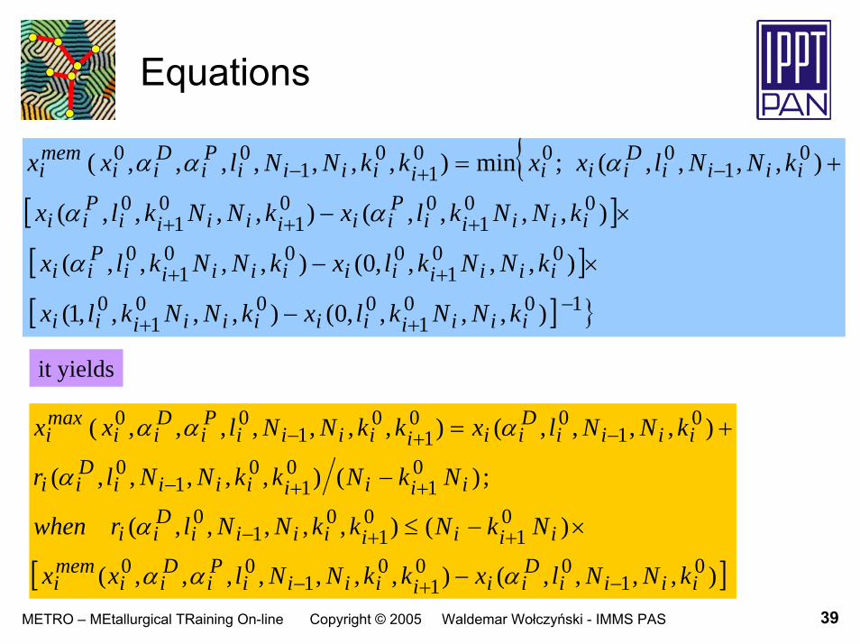
39METRO – MEtallurgical TRaining On-line Copyright © 2005 Waldemar Wołczyński - IMMS PAS
Equations
{[ ][ ][ ] }100
1000
10
001
0001
0
001
001
01
0
01
0001
01
00
),,,,0(),,,,1(
),,,,0(),,,,(
),,,,(),,,,(
),,,,(;min),,,,,,,(
−++
++
+++
−+−
−
×−
×−
+=
iiiiiiiiiiii
iiiiiiiiiiiPii
iiiiiPiiiiiii
Pii
iiiiDiiiiiiii
Pi
Dii
memi
kNNklxkNNklx
kNNklxkNNklx
kNNklxkNNklx
kNNlxxkkNNlxx
α
αα
ααα
it yields
[ ]),,,,(),,,,,,,(
)(),,,,,(
;)(),,,,,(
),,,,(),,,,,,,(
01
001
01
00
01
01
01
0
01
01
01
0
01
001
01
00
iiiiDiiiiiii
Pi
Dii
memi
iiiiiiiiDii
iiiiiiiiDii
iiiiDiiiiiii
Pi
Dii
maxi
kNNlxkkNNlxx
NkNkkNNlrwhen
NkNkkNNlr
kNNlxkkNNlxx
−+−
++−
++−
−+−
−
×−≤
−
+=
ααα
α
α
ααα

40METRO – MEtallurgical TRaining On-line Copyright © 2005 Waldemar Wołczyński - IMMS PAS
Equations
and
[ ]
[ ]
[ ]),,,,(),,,,,,,()(
),,,,,(
),,,,,(),,,,,(
01
001
01
0001
01
001
01
001
0
0
iiiiDiiiiiii
Pi
Dii
maxiiii
iiiDii
Biii
ix
minix
iiiDii
Biiii
Dii
minii
Bi
minix
kNNlxkkNNlxxNkN
dxkNlxxNNk
dxkNlxxNkNlxxxxN
−+−+
−+
−−
−−
=−∫
+−−+∫
ααα
α
αα
( ) ( )3min2
max2
min1
max1313221 /// xxxxxKKKK +−−≅= λλλλ
however
above equation is connected with the scheme shown in FIG. 8a

41METRO – MEtallurgical TRaining On-line Copyright © 2005 Waldemar Wołczyński - IMMS PAS
Simulation
FIG. 27
reproduction of planar (constant) profileof solute concentration (redistribution) and ratio of sub-layers thicknessaccording to the operatingrange FIG. 22 and full solidification path(phase diagram for stable equilibrium)
( ) ( )3min2
max2
min1
max1313221 /// xxxxxKKKK +−−≅= λλλλ
points come from EDS measurementsolidification arrested after 121 s

42METRO – MEtallurgical TRaining On-line Copyright © 2005 Waldemar Wołczyński - IMMS PAS
First solid / solid transformation
FIG. 28 first solid/solid transformation:2 Al3Ni Al3Ni2 + liquid (3Al)
liquid (Al) precipitates and diffusestowards the axis of symmetry of joint
N0 is conserved during first solid/solid transformation
when transformation is arrested then liquid (Al) shrinks and pores appear
RESULT time tMseems to be typical for a given system
first solid / solid transformationnamed as a „mantis” effect
43METRO – MEtallurgical TRaining On-line Copyright © 2005 Waldemar Wołczyński - IMMS PAS
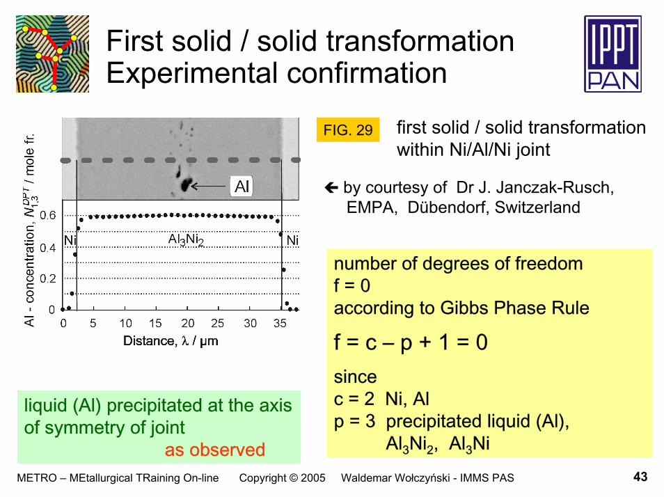
First solid / solid transformationExperimental confirmation
first solid / solid transformationwithin Ni/Al/Ni joint
FIG. 29
liquid (Al) precipitated at the axis of symmetry of joint
as observed
by courtesy of Dr J. Janczak-Rusch, EMPA, Dübendorf, Switzerland
number of degrees of freedom f = 0 according to Gibbs Phase Rule
f = c – p + 1 = 0sincec = 2 Ni, Alp = 3 precipitated liquid (Al),
Al3Ni2, Al3Ni

44METRO – MEtallurgical TRaining On-line Copyright © 2005 Waldemar Wołczyński - IMMS PAS
First solid / solid transformationExperimental confirmation
first solid / solid transformationwithin Fe/Zn/Fe joint
FIG. 30
liquid (Zn) precipitated at the axis of symmetry of joint
as observed
number of degrees of freedom
f = c – p + 1 = 0sincec = 2 Fe, Znp = 3 precipitated (Zn), δ, ζ
by courtesy of Prof. E.Guzik and Dr D. Kopyciński,University of Science and Technology,Kraków, Poland
FeZn13 FeZn10 + liquid (3Zn)ζ δ + liquid (3Zn)

45METRO – MEtallurgical TRaining On-line Copyright © 2005 Waldemar Wołczyński - IMMS PAS
Simulation
FIG. 31
reproduction of the Al-solute redistribution acrossAl3Ni2–Al3Ni multi-layer being in the contact with a Ni – substratereduced solidification path; model referredto phase diagram for stable equilibrium
RESULT plane profile of simulated redistribution, ki+1Ni, is obtainable, only

46METRO – MEtallurgical TRaining On-line Copyright © 2005 Waldemar Wołczyński - IMMS PAS
Simulation
FIG. 32
reproduction of the Zn-solute redistribution across δ–ζ multi-layer being in the contact with a (Γ + Fe) – substratefull solidification path; model referredto phase diagram for stable equilibrium
RESULT plane profile of simulated redistribution, ki+1Ni, is obtainable, only

47METRO – MEtallurgical TRaining On-line Copyright © 2005 Waldemar Wołczyński - IMMS PAS
Sequence
sequence of phase appearance during solidification according to
1/ the dx model (simulation):first Al3Ni2 next Al3Ni
2/ phase diagram for stable equilibrium(peritectic reactions):
first Al3Ni2 next Al3Ni3/ the birth: FIG. 16
first Al3Ni2 next Al3Ni4/ criterion of maximum temperature
of the s / l interface(metastable conditions):
first Al3Ni2 next Al3Ni
full solidification path; phasediagram for stable equilibriumformation of peritectic phases:primary xi + liquid (Ni) ki+1NiFIG. 33

48METRO – MEtallurgical TRaining On-line Copyright © 2005 Waldemar Wołczyński - IMMS PAS
Sequence Theorem of maximum driving force
FIG. 34
the dominant phaseAl3Ni2appears first during solidification
by courtesy of Dr J. Golczewski, Senior ScientistMax-Planck Institut für Metallforschung, Stuttgart, Germany

49METRO – MEtallurgical TRaining On-line Copyright © 2005 Waldemar Wołczyński - IMMS PAS
Sequence Theorem of maximum driving force
the coupled phase Al3Niis consumed bythe dominant phase Al3Ni2during first s/s transformation, FIG. 35a
the dominant phase δappears first during solidificationFIG. 35b
FIG. 35
a/ first s/s transformationb/ solidification
by courtesy of Prof. Hyuck-Mo LeeAdvanced Institute of Science and Technology, Yusung-Gu, Taejon, Korea

50METRO – MEtallurgical TRaining On-line Copyright © 2005 Waldemar Wołczyński - IMMS PAS
Arrested solidification Frozen morphology
FIG. 36solidification arrested during the formation of the Ni-Al-Ni – joint
the thickening of the Al3Ni intermetallic compound continues (due to an applied arresting) along solidification path:NF NE, (FIG. 23)this is accompanied by the appearance of an inter-layer of frozen (Al)M
in the middle an eutectic: [Al3Ni+(Al)S] is visiblethe (Al)M and (Al)S phases arethe metastable and stable eutectic phases, respectively
thickening rate depends oncrystallographic orientation of a given cell
by courtesy of Dr J. Janczak-Rusch, EMPA, Dübendorf, Switzerland

51METRO – MEtallurgical TRaining On-line Copyright © 2005 Waldemar Wołczyński - IMMS PAS
Concluding remarks
the current model equations could be successfully appliedto simulation with the use of phase diagram for metastable equilibriumsimulated profiles would be more flexible to fit perfectly experimental pointseach slope of measured profile would be reproducible
the present description is able to give information about a value of diffusion coefficient, Dsbut analysis of the definition of back-diffusion parameter is needed
the proposed model could be developed for multi-component systems but determination of solidification path becomes more complicatedas shown by H-W mode of calculation
H-W T. Himemiya, W. Wołczyński, Materials Transactions, The Japan Institute of Metals, 43, (2002), 2890-2896

METRO MEtallurgical TRaining On-line
Education and Culture
Solidification / microsegregation modelapplied to description of
diffusion soldering / brazing
End of the lecture