Solidification || Controlling the Macro Structure of Cast Metals
41
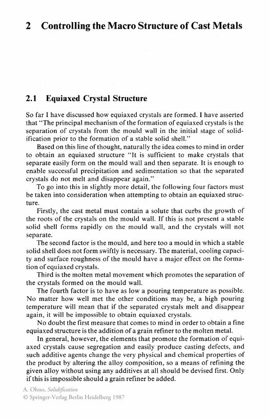
2 Controlling the Macro Structure of Cast Metals 2.1 Equiaxed Crystal Structure So far I have discussed how equiaxed crystals are formed. I have asserted that "The principal mechanism of the formation of equiaxed crystals is the separation of crystals from the mould wall in the initial stage of solid- ification prior to the formation of a stable solid shell." Based on this line of thought, naturally the idea comes to mind in order to obtain an equiaxed structure "It is sufficient to make crystals that separate easily form on the mould wall and then separate. It is enough to enable successful precipitation and sedimentation so that the separated crystals do not melt and disappear again." To go into this in slightly more detail, the following four factors must be taken into consideration when attempting to obtain an equiaxed struc- ture. Firstly, the cast metal must contain a solute that curbs the growth of the roots of the crystals on the mould wall. If this is not present a stable solid shell forms rapidly on the mould wall, and the crystals will not separate. The second factor is the mould, and here too a mould in which a stable solid shell does not form swiftly is necessary. The material, cooling capaci- ty and surface roughness of the mould have a major effect on the forma- tion of equiaxed crystals. Third is the molten metal movement which promotes the separation of the crystals formed on the mould wall. The fourth factor is to have as Iowa pouring temperature as possible. No matter how well met the other conditions may be, a high pouring temperature will mean that if the separated crystals melt and disappear again, it will be impossible to obtain equiaxed crystals. No doubt the first measure that comes to mind in order to obtain a fine equiaxed structure is the addition of a grain refiner to the molten metal. In general, however, the elements that promote the formation of equi- axed crystals cause segregation and easily produce casting defects, and such additive agents change the very physical and chemical properties of the product by altering the alloy composition, so a means of refining the given alloy without using any additives at all should be devised first. Only if this is impossible should a grain refiner be added. A. Ohno, Solidification © Springer-Verlag Berlin Heidelberg 1987
Transcript of Solidification || Controlling the Macro Structure of Cast Metals
2 Controlling the Macro Structure of Cast Metals
2.1 Equiaxed Crystal Structure
So far I have discussed how equiaxed crystals are formed. I have asserted that "The principal mechanism of the formation of equiaxed crystals is the separation of crystals from the mould wall in the initial stage of solidification prior to the formation of a stable solid shell."
Based on this line of thought, naturally the idea comes to mind in order to obtain an equiaxed structure "It is sufficient to make crystals that separate easily form on the mould wall and then separate. It is enough to enable successful precipitation and sedimentation so that the separated crystals do not melt and disappear again."
To go into this in slightly more detail, the following four factors must be taken into consideration when attempting to obtain an equiaxed structure.
Firstly, the cast metal must contain a solute that curbs the growth of the roots of the crystals on the mould wall. If this is not present a stable solid shell forms rapidly on the mould wall, and the crystals will not separate.
The second factor is the mould, and here too a mould in which a stable solid shell does not form swiftly is necessary. The material, cooling capacity and surface roughness of the mould have a major effect on the formation of equiaxed crystals.
Third is the molten metal movement which promotes the separation of the crystals formed on the mould wall.
The fourth factor is to have as Iowa pouring temperature as possible. No matter how well met the other conditions may be, a high pouring temperature will mean that if the separated crystals melt and disappear again, it will be impossible to obtain equiaxed crystals.
No doubt the first measure that comes to mind in order to obtain a fine equiaxed structure is the addition of a grain refiner to the molten metal.
In general, however, the elements that promote the formation of equiaxed crystals cause segregation and easily produce casting defects, and such additive agents change the very physical and chemical properties of the product by altering the alloy composition, so a means of refining the given alloy without using any additives at all should be devised first. Only if this is impossible should a grain refiner be added.
A. Ohno, Solidification© Springer-Verlag Berlin Heidelberg 1987

2.1 Equiaxed Crystal Structure 43
For alloys in which equiaxed crystals do not form even if the pouring temperature is lowered and the mould is agitated, rather, than adding a grain refiner it would be better to take some measure towards the mould wall itself so that necked-shape crystals for there, and to make them separate.
Let us begin with a discussion of grain refiners.
2.1.1 Crystal Grain Refiners
The Action of Grain Refiners
About 10 years ago when 1 visited Aachen Technical University in Germany 1 met a graduate student who had already been studying ingot crystal grain refiners for six years. He was a student from Luxembourg called Phillippe, and lined up on his desk in the laboratory was an array of glass bottles containing every possible kind of powder gathered from around the world, such as oxides, carbides and nitrides.
Laying on his desk was a powder injector made by renovating an air gun. He said "I use this to inject these powders into the flow of molten steel during the pouring, and an investigating the effect they have in refining the crystals in the steel." This was just like the experiments carried out by alchemists of old.
I said "Surely they have no effect, though they would act as a coolant." He replied "You're perfectly right. They have no effect except when
added directly above freezing point. They just make the steel dirty." Apparently such experiments are being attempted here and there
around the world. A careful perusal of articles that claim that in such an experiment
"crystals were refined" by adding grains with a completely different solid from the primary crystals of the alloy - i.e. alien grains - reveals that in most cases a cold solid powder was added directly in front of the growing solid shell, and then the crystals became fine.
As I stated beforehand in the section on the origin of the formation of equiaxed crystals, if a cold charge is projected into the molten metal its surface can cause the formation of equiaxed crystals. This is because such a powder functions as an internal chill. It must be made clear, however, that this only works in the case of a cold charge. No crystal-refining effect can be expected by adding it in advance while the steel is molten and making it float. One will merely end up with a dirty steel ingot.
It is known that the addition of a tiny amount ofTi is effective in refining AI. This has long been attributed to the formation of a nucleus by TiC.
Figure 2.1 shows the macro structure of an ingot solidified under conditions in which 0.04% Ti was added to Al and the surface of the molten metal was made to move slightly.
44 2 Controlling the Macro Structure of Cast Metals
(a) (b)
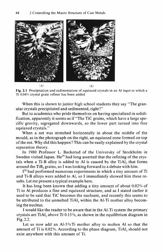
Fig. 2.1 Precipitation and sedimentation of equiaxed crystals in an Al ingot to which a Ti 0.04% crystal grain refiner has been added
When this is shown to junior high school students they say "The granular crystals precipitated and sedimented, right?"
But to academics who pride themselves on having specialized in solidification, apparently it seems as if "The TiC grains, which have a large specific gravity, segregated downwards, so the lower part turned into fine equiaxed crystals."
When a net was stretched horizontally in about the middle of the mould, as in the photograph on the right, an equiaxed zone formed on top of the net. Why did this happen? This can be easily explained by the crystal separation theory.
In 1980 Professor L. Backerud of the University of Stockholm in Sweden visited Japan. He l9 had long asserted that the refining of the crystals when a Ti-B alloy is added to Al is caused by the TiAl3 that forms around the TiB2 grains, so I was looking forward to a debate with him.
120 had performed numerous experiments in which a tiny amount ofTi and Ti-B alloys were added to AI, so I immediately showed him these results. Let me present a typical example here.
It has long been known that adding a tiny amount of about 0.02 % of Ti to Al produces a fine and equiaxed structure, and as I stated earlier it used to be said that TiC becomes the nucleant, and recently this seems to be attributed to the unmelted TiAl3 within the AI-Ti mother alloy becoming the nucleus.
I would like the reader to be aware that in the AI-Ti system the primary crystals are TiAl3 above Ti 0.15%, as shown in the equilibrium diagram in Fig. 2.2.
Let us now add an AI-5 % Ti mother alloy to molten Al so that the amount of Ti is 0.02 %. According to the phase diagram, TiAl3 should not exist anywhere with this amount of Ti.

800 liquid s.>
~ z ~ ~ 700 E '" I-
2.1 Equiaxed Crystal Structure 4S
liquid + TiAI3
a + TiAI J
Ti(wt%)
Fig. 2.2 AI-Ti system alloy equilibrium phase diagram
However, when the mother alloy is added to the Al molten metal directly above freezing point and it is cast before the TiAI3 in the mother alloy is fully melted, equiaxed crystals are formed, centering on TiAI3• If the TiAI3 survives locally as primary crystals, a peritectic reaction should occur there centering on this.
But if these TiAI3 grains melt completely, there is no longer any nucleus, so refining of the crystals cannot be expected as long as one adheres to the nucleation theory.
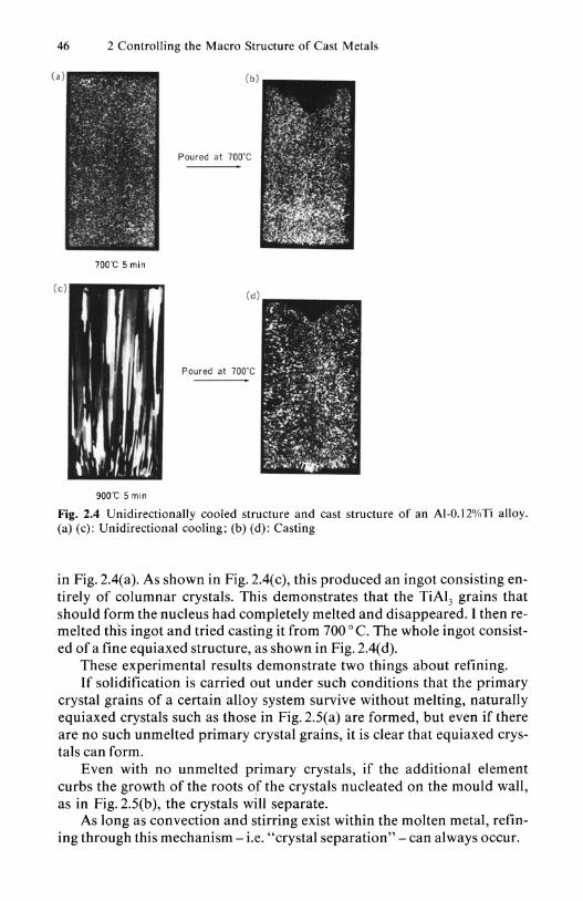
Figure 2.3 is an actual example that I showed to Professor Backerud. Using an AI-5% Ti mother alloy, I added Al so that it would become Ti 0.12%. Using equipment such as that shown in Fig. 2.3(a), I melted this at 700 0 C, and after a five-minute lapse I cooled it unidirectionally from below with water. As shown in Fig.2.4(a) this produced a structure consisting solely of equiaxed crystals. After remelting this ingot and pouring it into a metallic mould as in Fig. 2.3(b), naturally the structure again consisted entirely of fine equiaxed crystals, as shown in Fig. 2.4(b).
Based on this evidence alone it may be inevitable that it is said that the equiaxed crystals formed because the TiAI3 grains became the nucleus.
Next, however, I subjected this alloy to melting at 900 0 C for a period of five minutes, then cooled it unidirectionally from below as in the case
I "~ - I '\'""
" ~o D .
:._ U=,-I'I ~ _.~ 0
. , ---
~. S" o ·
: . . 0
'--- I I~
Pourilg --.....Metallic
, mould Electric
...... Iurnace
:"II:~I,n : Water (oollnl
(a) (b)
Fig. 2.3 Unidirectional solidification and metallic mould casting
46 2 Controlling the Macro Structure of Cast Metals
(a) ( b )
Poured at 700·C
700e; 5 min
Poured at 700·C
900'C 5 min
Fig. 2.4 Unidirectionally cooled structure and cast structure of an AI-O.12%Ti alloy. (a) (c): Unidirectional cooling; (b) (d): Casting
in Fig. 2.4(a). As shown in Fig. 2.4(c), this produced an ingot consisting entirely of columnar crystals. This demonstrates that the TiAl3 grains that should form the nucleus had completely melted and disappeared. I then remelted this ingot and tried casting it from 700 0 C. The whole ingot consisted of a fine equiaxed structure, as shown in Fig. 2.4( d).
These experimental results demonstrate two things about refining. If solidification is carried out under such conditions that the primary
crystal grains of a certain alloy system survive without melting, naturally equiaxed crystals such as those in Fig. 2.5(a) are formed, but even if there are no such un melted primary crystal grains, it is clear that equiaxed crystals can form.
Even with no unmelted primary crystals, if the additional element curbs the growth of the roots of the crystals nucleated on the mould wall, as in Fig. 2.5(b), the crystals will separate.
As long as convection and stirring exist within the molten metal, refining through this mechanism - i.e. "crystal separation" - can always occur.
2.1 Equiaxed Crystal Structure 47
(.) --~~,----,~~ - (:1= =---=-TiAI 3 • ~~TiA~ - - :: - -- - - -Molten metal ---- -- - - - -
~I--- ---~~~_:e~~ (b) _ __ _
---------------
Mould - - -- - -
tJ@J--=- - ~ ~I~ -----=--== -a ·Crystals - - - - -
-::=~ -===-~D~ - - -- - -- -- ----- -----
Mould- ---- Mould --- -
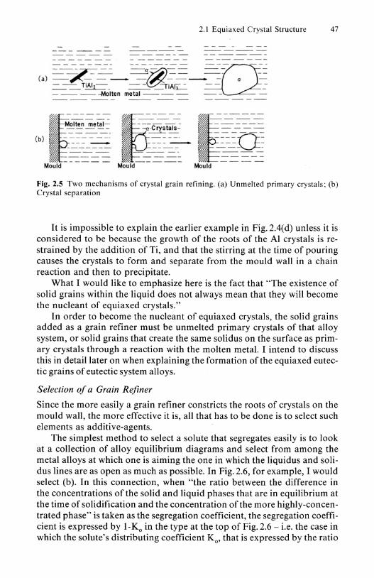
Fig_ 2.5 Two mechanisms of crystal grain refining. (a) Un melted primary crystals ; (b) Crystal separation
It is impossible to explain the earlier example in Fig. 2.4( d) unless it is considered to be because the growth of the roots of the Al crystals is restrained by the addition of Ti, and that the stirring at the time of pouring causes the crystals to form and separate from the mould wall in a chain reaction and then to precipitate.
What I would like to emphasize here is the fact that "The existence of solid grains within the liquid does not always mean that they will become the nucleant of equiaxed crystals."
In order to become the nucleant of equiaxed crystals, the solid grains added as a grain refiner must be unmelted primary crystals of that alloy system, or solid grains that create the same solidus on the surface as primary crystals through a reaction with the molten metal. I intend to discuss this in detail later on when explaining the formation of the equiaxed eutectic grains of eutectic system alloys.
Selection of a Grain Refiner
Since the more easily a grain refiner constricts the roots of crystals on the mould wall, the more effective it is, all that has to be done is to select such elements as additive-agents.
The simplest method to select a solute that segregates easily is to look at a collection of alloy equilibrium diagrams and select from among the metal alloys at which one is aiming the one in which the liquidus and solidus lines are as open as much as possible_ In Fig_ 2.6, for example, I would select (b). In this connection, when "the ratio between the difference in the concentrations of the solid and liquid phases that are in equilibrium at the time of solidification and the concentration of the more highly-concentrated phase" is taken as the segregation coefficient, the segregation coefficient is expressed by 1-Ko in the type at the top of Fig. 2.6 - i.e. the case in which the solute's distributing coefficient Ko, that is expressed by the ratio
48 2 Controlling the Macro Structure of Cast Metals
between the solute concentration C, of the liquidus line and the concentration Cs of the solidus line that are in equilibrium,
Ko = C/C,
is smaller than I. It is expressed by I-I/Ko in the type at the bottom of Fig. 2.6 - i.e. the case of a solute whose distributing coefficient Ko is larger
Ti(0.97) Ni (0.99)
Cu (0.83) Mn (0.70)
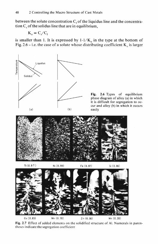
Fig. 2.6 Types of equilibrium phase diagram of alloy (a) in which it is difficult for segregation to occur and alloy (b) in which it occurs easily
Fe (0.97) Si (0.86)
Zn (0.56) Mn (0.30)
Fig. 2.7 Effect of added elements on the solidified structure of AI. Numerals in parentheses indicate the segregation coefficient
2.1 Equiaxed Crystal Structure 49
than 1. The greater is the value, the more effective is the solute as a grain refiner.
In the case of Al alloys, this value is large in Ti, Ni, Fe and so on, and when a tiny amount of such elements is added in actual practice, it is easy for the structure to become refined, as in Fig. 2.7. Refining does not readily occur when elements with a small such value are added, such as Zn and Mn.
However, the segregation coefficient cited here was calculated on the basis of existing equilibrium diagrams, and there is a need for further detailed examination of each of these values.
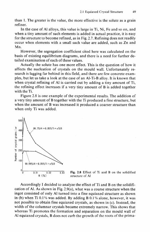
Actually the solute has one more effect. This is the question of how it affects the nucleation of crystals on the mould wall. Unfortunately research is lagging far behind in this field, and there are few concrete examples, but let us take a look at the case of an AI-Ti-B alloy. It is known that when crystal refining of Al is carried out by adding a tiny amount of Ti, the refining effect increases if a very tiny amount of B is added together with theTi.
Figure 2.8 is one example of the experimental results. The addition of a very tiny amount of B together with the Ti produced a fine structure, but when the amount of B was increased it produced a coarser structure than when only Ti was added.
~ 500
i 400 .\99.7%AI+0.05%Ti+X%B
~ "l
F·\--~~ w.,,%,,~. zlOO \ '"~ 00':---""'0"".0""1 ----=O-'o.0c=-2--.,..0.~03 Fig. 2.8 Effect of Ti and B on the solidified
B (%) structure of Al
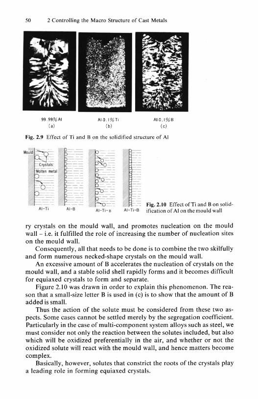
Accordingly I decided to analyze the effect of Ti and B on the solidification of AI. As shown in Fig. 2.9(a), what was a coarse structure when the ingot consisted of only Al turned into a fine equiaxed structure as shown in (b) when Ti 0.1 % was added. By adding B 0.1 % alone, however, it was not possible to obtain fine equiaxed crystals, as shown in (c). Instead, the width of the columnar crystals became extremely narrow. This shows that whereas Ti promotes the formation and separation on the mould wall of Al equiaxed crystals, B does not curb the growth of the roots of the prima-
50 2 Controlling the Macro Structure of Cast Metals
99.99% AI (a)
AI·O.I%Ti (b)
AI·O.I%B (e)
Fig. 2.9 Effect of Ti and B on the solidified structure of Al
AI-Ti AI-8 Fig. 2.10 Effect ofTi and B on solid
AI-Ti-8 ification of Al on the mould wall
ry crystals on the mould wall, and promotes nucleation on the mould wall - i.e. it fulfilled the role of increasing the number of nucleation sites on the mould wall.
Consequently, all that needs to be done is to combine the two skilfully and form numerous necked-shape crystals on the mould wall.
An excessive amount of B accelerates the nucleation of crystals on the mould wall, and a stable solid shell rapidly forms and it becomes difficult for equiaxed crystals to form and separate.
Figure 2.1 0 was drawn in order to explain this phenomenon. The reason that a small-size letter B is used in (c) is to show that the amount of B added is small.
Thus the action of the solute must be considered from these two aspects. Some cases cannot be settled merely by the segregation coefficient. Particularly in the case of multi-component system alloys such as steel, we must consider not only the reaction between the solutes included, but also which will be oxidized preferentially in the air, and whether or not the oxidized solute will react with the mould wall, and hence matters become complex.
Basically, however, solutes that constrict the roots of the crystals play a leading role in forming equiaxed crystals.

2.1 Equiaxed Crystal Structure 51
2.1.2 Mould Cooling Capacity
As I said earlier, grain refiners should only be added as a last resort, and in order to refine the crystals efforts should be made rather from the aspect of the mould or the pouring temperature. Let me begin here by firstly discussing the effect of the mould on the formation of equiaxed crystals.
I said that when the degree of undercooling rises above a certain level, equiaxed crystals do not form and separate, and a stable solid shell forms on the mould wall right from the start, producing a columnar zone.
This shows that the greater is the cooling capacity of the mould, the more rapidly does a stable solid shell form and the more difficult it is for equiaxed crystals to form and separate.
Compared to a mould with a large cooling capacity, it takes more time in a mould made from a material with a small cooling capacity for the crystals to come in contact with adjacent crystals and form a solid shell on the mould wall. Thus if there is movement of the molten metal within the liquid near the mould wall, as in Fig. 2.11(a), the possibility of crystal separation exists. By contrast, when a mould with a large cooling capacity, such as a water-cooled metallic mould, is used, a stable solid shell rapidly forms on the mould wall, as in Fig. 2.11 (b). In this case crystals have less chance to separate than in Fig. 2.11(a), but whether or not it is completely impossible depends on the configuration of the primary crystals and the movement of the molten metal. If they are crystals whose configuration facilitates separation, perhaps a few crystals may be able to separate before the formation of the stable solid shell.
=----~-~ten metal - -- -- R~S~
(a) -r7-~ -Mould
Molten metal-----=-==---:O: ---------
Fig. 2.11 Mould cooling capacity and the solidification phenomenon on the mould wall
Once a stable solid shell has formed, however, it is difficult for crystals to separate even if movement of the molten metal exists, and they form a columnar zone on the mould wall.
Thus it is more difficult for equiaxed crystals to form and separate in a quenching mould than in a sand or other mould, but if free crystals - i.e. equiaxed crystals - are transported from some other site, the crystals that have escaped remelting by the molten metal would sediment and a fine equiaxed zone would appear on top of them.
52 2 Controlling the Macro Structure of Cast Metals
(b) <al
Let me explain this with a simple example.
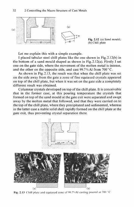
Fig. 2.12 (a) Sand mould; (b) Chill plate
I placed tabular steel chill plates like the one shown in Fig. 2.12(b) in the bottom of a sand mould shaped as shown in Fig. 2.l2(a). Firstly I set one on the gate side, where the movement of the molten metal is intense, and the other on the opposite side, and cast 99.7% Al from 700 0 C.
As shown in Fig. 2.13, the result was that when the chill plate was set on the side away from the gate a zone of fine equiaxed crystals appeared on top of the chill plate, but when it was set on the gate side a completely different result was obtained.
Columnar crystals developed on top of the chill plate. It is conceivable that in the former case, at this pouring temperature the crystals that formed on top of the sand mould at the gate exit were separated and swept away by the molten metal that followed, and that they were carried on to the top of the chill plate, where they precipitated and sedimented, whereas in the latter case a stable solid shell rapidly formed on the chill plate at the gate exit, thus preventing crystal separation there.
Fig. 2.13 Chill plate and equiaxed zone of 99.7"IrIAI casting poured at 700 'T

2.1 Equiaxed Crystal Structure 53
Fig. 2.14 Chill plate and equiaxed zone of 99.7%Al casting poured at 680 0 C
The site at which crystals form and separate - i.e. the origin of the formation of equiaxed crystals - migrates towards the gate or the pouring entrance as the pouring temperature falls.
Figure 2.14 shows the results of pouring 99.7% Al from 680°C using a similar mould.
The reader will realize that the equiaxed zone of the casting does not differ so greatly depending on the location of the chill plate as when pouring was carried out at 700 ° C. I believe this is owing to the fact that the site where equiaxed crystals form has migrated to the inner wall of the sprue runner or the gate.
These experimental results demonstrate that a chill plate is useful in preventing the remelting and disappearance of crystals that have formed and separated at another location and moved to this location. When placed at a site where crystal formation and separation is desired, however, the cooling capacity of the mould wall there increases, and rather the chill plate suppresses the formation and separation of equiaxed crystals.
Let me describe the interesting results of an experiment 'S in which 99.8%Al was poured into moulds made of various different materials.
Figure 2.15 shows the casting equipment used. In order to standardize the pouring conditions, the molten metal was poured by using a tun dish and pulling up the stopper.
So that unevenness in the edge of the pouring mouth in the bottom of the tundish would not affect the solidified structure, I finished the edge off

54 2 Controlling the Macro Structure of Cast Metals
5 topper
Cruc,ble
Molten_+H-:1~ metal
N ozzle-lt±::!fi!::;l
Pouring height .dJustor
C.A . lhermo- couple
~-1<1"1."....Electric lurnace
- Mould
Fig. 2.15 a ling equipment
~ 60 r--------------------' 99 . 79% AI 0 : Copper . : Aluminum • : Bronze
.§ SO ~ go 40 Q. P ou Ii n g tempera lu re
~ 30
~ 20
~ 10 ""2
680l:
; O~~~ __ ~ __ ~ __ ~ __ ~ ~ 0 20 40 60 80 100
Average heat liu. (kcal m 1sec)
• : Cast ,ron • : Graphi te • : St.inless steel
• : Carbon . : Resin- coated sand ste.1
Fig. 2.16 Effect of mould cooling capacity on formation of equiaxed crystals
smoothly and ensured that the pouring location and the distance between the outlet and the mould would be uniform.
The moulds were book moulds, and were made using resin-coated sand, graphite, cast iron, carbon steel, stainless steel, brass, aluminum and copper.
Figure 2.16 displays the relationship between the proportion of the equiaxed crystal area in the ingots obtained by pouring 99.8% Al from 680 0 C and the cooling capacity of the moulds - i.e. the average heat flux.
Using the copper mould, the average heat flux was increased beyond 85 Kcal/m2 sec. This is resulted in a rapid decrease in the equiaxed crystal area proportion.
This tendency appears clearly when the pouring temperature is low, but as the pouring temperature rises it gradually becomes less obvious, and even in this case it was not observed above 750 0 C, and the structure consisted entirely of columnar crystals.
I do not think that this is particularly strange, and regard it as a matter of course that such sudden structural changes occur, but apparently it
Gradually- cooled mould
ta ble solid shel t=
(a) (b)
2.1 Equiaxed Crystal Structure 55
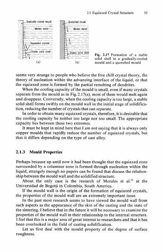
Fig. 2.17 Formation of a stable solid shell in a gradually-cooled mould and a quenched mould
seems very strange to people who believe the free chill crystal theory, the theory of nucleation within the advancing interface of the liquid, or that the equiaxed zone is formed by the partial remelting of dendrites.
When the cooling capacity of the mould is small, even if many crystals separate from the mould as in Fig.2.17(a), most of them would melt again and disappear. Conversely, when the cooling capacity is too large, a stable solid shell forms swiftly on the mould wall in the initial stage of solidification, reducing the number of crystals that can separate.
In order to obtain many equiaxed crystals, therefore, it is desirable that the cooling capacity be neither too large nor too small. The appropriate capacity lies between these two extremes.
It must be kept in mind here that I am not saying that it is always only copper moulds that rapidly reduce the number of equiaxed crystals, but that it differs depending on the type of cast alloy.
2.1.3 Mould Properties
Perhaps because up until now it had been thought that the equiaxed zone surrounded by a columnar zone is formed through nucleation within the liquid, strangely enough no papers can be found that discuss the relationship between the mould wall and the solidified structure.
About the only case is the research of Morales et al.21 at the Universidad de Bogota in Colombia, South America.
If the mould wall is the origin of the formation of equiaxed crystals, the properties of the mould wall are an extremely important issue.
In the past most research seems to have viewed the mould wall from such aspects as the appearance of the skin of the casting and the state of the sintering. I believe that in the future it will be necessary to examine the properties of the mould wall in their relationship to the internal structure. I feel that this is a major area of great interest to researchers and that it has been overlooked in the field of casting solidification.
Let us first deal with the mould property of the degree of surface roughness.

56 2 Controlling the Macro Structure of Cast Metals
Supposing that the mould material is perfectly homogeneous both physically and chemically, if the mould wall is specular the crystals that have nucleated there will grow inhindered along the mould wall as the surface of the molten metal rises, as in Fig. 2.18(a), and will form a stable solid shell.
(al ( bl
Fig. 2.18 Surface roughness of mould and growth of crystals
However, when the wall is uneven and the molten metal cannot completely fill in the uneven valleys, as in Fig. 2.l8(b), crystal growth is temporarily obstructed at these valleys, and fresh nucleation occurs at the edge of the next protrusion.
Generally the surface of the molten metal is covered with an oxide film, and as long as this oxide film does not react with the mould material the molten metal will not readily fill in the fine holes. Gaps will form in the uneven valleys. Naturally, when the unevenness becomes excessive, the molten metal completely buries the valleys also.
<al ( b)
Fig. 2.19 Solidified structure and surface roughness of mould

2.1 Equiaxed Crystal Structure 57
Let us look at this by means of a simple experiment. As shown in Fig. 2.19, one side of the mould was buffed to a specular surface, while the other was polished with sandpaper to produce a steel mould with a rough surface, into which 99.8% Al was cast. As you can see, more columnar crystals were formed on the side with a rough surface than on the side with a specular surface, revealing that more crystal nuclei were produced on the right-hand surface.
This suggests that giving the mould wall a rough surface increases the number of nucleation sites on the mould wall, and since the uneven valleys on the wall prevent growth along the mould wall, it also facilitates crystal separation.
Figure 2.20 investigates the relationship between the proportion of the equiaxed crystal area in the ingot and the roughness of the mould wall when 99.8 % Al is poured from 680 0 C, with the roughness of the inner wall of the steel mould being changed to various degrees.
--;; 100,----,----,-------,----, 2) Pouring height
g "200mm ~o t 75 ~ 175mm g. 0 150mm l5.
~ 500
. /"------~ ~/ 125~~' "g. 0 t/o Pouring temperature 680'(;
w 0 10 20 30 40
Surface roughness of mould (,umRmax)
Fig. 2.20 Effect of roughness of mould surface and pouring height on equiaxed crystal area proportion of 99.8%AI ingot
As this plainly shows, the equiaxed crystal area increases as the roughness increases. The higher is the pouring height, the greater is the effect of such surface roughness. This is because higher pouring heights promote crystal separation.
Here I have only investigated up to 30Rmax, but I believe that if the roughness is excessive the molten metal would bury the uneven valleys, and a stable solid skin would form and crystal separation become difficult. The curve would probably drop sharply.
Our discussion so far refers to cases in which the mould is made of a single material. Let us now consider cases in which the mould consists of a mixture of two or more materials.
In the case of a mould made from two or more materials, the crystals would nucleate preferentially on the material in which it is easy for nucleation to occur, as in Fig. 2.21. The extent to which this material is distributed would greatly influence the formation of equiaxed crystals. The question is what should be mixed in the mould wall and what will form a site for crystal nucleation.

58 2 Controlling the Macro Structure of Cast Metals
'i . ---
Fig. 2.21 Effective nucleation site for formation of equiaxed crystals
( a) (b)
Fig. 2.22 Reaction at the interface between molten steel and Si02 mould
Perhaps I am not the only person who always watches to see from where the froth will form when beer is poured into a glass. Bubbles also form when water is poured into a beaker and heated. In this case too the bubbles appear continuously from a certain place in the bottom of the beaker. I find it extremely tantalizing why they should only appear from that place.
Readers who have seen our film on the formation of equiaxed crystals in an Sn-Bi alloy must have realized that the crystals form and separate from the same place.
Equiaxed crystals continuously form and separate form a certain point on the mould wall- i.e. the nucleation site. Beer froth, the bubbles in boiling water, and equiaxed crystals in cast metals all form and separate continuously from the nucleation site.
The question of what kind of place on the mould wall forms the nucleation site in the case of cast metals is of great interest. If this is known, all we have to do is to distribute appropriately in the mould wall materials that will lead to the formation of such nucleation sites.
Since no research reports on this are available, let me introduce an experiment we performed.
Since casting is carried out in the air except in special circumstances, an oxide film forms on the surface of the molten metal poured. This reacts with the air, moisture and so on adsorbed to the mould wall, and creates an oxide.
The composition of the oxide film is extremely important. Of the components contained in the molten metal, the oxides of the elements that are oxidized preferentially will come to the surface first.
I am sure that the reader is well aware that sintering occurs when these oxides react with the mould material. If Mn steel is cast into a mould consisting of an acidic oxide such as Si02, MnO, which is a strong basic oxide film, forms on the surface of the molten metal, and the Si02 and MnO react as in Fig. 2.22. The steel sinters to the mould.
If Cr steel is cast, a neutral oxide film, Cr20 3, forms on the surface of the molten metal, so steel does not sinter to the mould.
2.1 Equiaxed Crystal Structure 59
Mould material 8 Mixtu re 01 A and 8 "
--------- --
-- ---- --
0 ------\ ---0 -- ---
" _ 0 ___
(a) (b) (c)
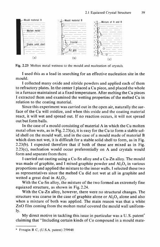
Fig. 2.23 Molten metal wetness to the mould and nucleation of crystals
I used this as a lead in searching for an effective nucleation site in the mould.
I collected many oxide and nitride powders and applied each of them to refractory plates. In the center I placed a Cu piece, and placed the whole in a furnace maintained at a fixed temperature. After melting the Cu pieces I extracted them and examined the wetting properties of the melted Cu in relation to the coating material.
Since this experiment was carried out in the open air, naturally the surface of the Cu will oxidize, and when this oxide and the coating material react, it will wet and spread out. If no reaction occurs, it will not spread out but form balls.
In the case of a mould consisting of material A in which the Cu molten metal often wets, as in Fig. 2.23(a), it is easy for the Cu to form a stable solid shell on the mould wall, and in the case of a mould made of material B which does not wet, it is difficult for a stable solid shell to form, as in Fig. 2.23(b). I expected therefore that if both of these are mixed as in Fig. 2.23(c), nucleation would occur preferentially on A and crystals would form and separate from there.
I carried out casting using a Cu-Sn alloy and a Cu-Zn alloy. The mould was made of graphite, and I mixed graphite powder and Al20 3 in various proportions and applied the mixture to the inner walls. I selected these two as representatives since the melted Cu did not wet at all in graphite and wetted a great deal in A120 3•
With the Cu-Sn alloy, the mixture of the two formed an extremely fine equiaxed structure, as shown in Fig. 2.24.
With the Cu-Zn alloy, however, there were no structural changes. The structure was coarse in the case of graphite alone or Al20 3 alone and also when a mixture of both was applied. The main reason was that a white ZnO film coming from the molten metal covered the mould wall uniformly.
My direct motive in tackling this issue in particular was a U. S. patent' claiming that "Including certain kinds of Co compound in a mould mate-
* Freagin R C, (U.S.A. patent) 259948

60 2 Controlling the Macro Structure of Cast Metals
Graphite Graphite + 12% A1 20 3
Graphite +20% AI 203
Graphite +SO%AI2 0 3
Fig. 2.24 Macro structure of Cu-Sn alloy poured into mould consisting of graphite and Al20 3
rial is effective in crystal grain refinement ofNi base alloys and Co base alloys, but they have no effect ifput directly into the molten metal".
I felt sure that the Co compounds must have acted effectively as nucleation sites in the mould wall with regard to these alloys. I decided to examine why the Co compounds were effective, and to study systematically what kind of materials are capable of acting as effective nucleants in various different alloys.
Since the question of what acts as an effective nucleation site for the formation of equiaxed crystals is an unexplored area which has not been touched on at all in the field of casting, I would like to see many researchers focus on this issue in the future instead of on research into crystal grain refiners for adding to molten metal, which is a field to which many researchers have devoted their time and energy in the past.
What I would particularly like to say to people wishing to carry out such research is not only "When looking at the mould wall, do not forget the existence of the invisible things adsorbed to it, such as air, humidity and dust", but also "No matter how thin it may be, an oxide film will form on the surface of the molten metal poured into the mould, and depending on the alloy, nitrides may form. Non-metallic inclusions may also be floating in the molten metal." I would like future researchers to keep these facts in mind.
If the surface of the molten metal oxidizes, it is not the mould wall and molten metal that come into direct contact, but the oxide film and the mould wall. Consequently, the old theory on nucleation that "The structure of the crystals of the material that acts as the substrate for crystal nucleation and those of the cast metal must resemble each other closely" is of no use between the mould wall and the molten metal.
At high temperatures perhaps a reaction may occur between such an oxide film and somewhere on the mould wall. If full attention is paid to these factors as research moves forward, I believe that the riddle of the effective nucleation site for the formation of equiaxed crystals will surely be solved.

2.1 Equiaxed Crystal Structure 61
2.1.4 Vibration
Role of Vibration
It is known that vibrating or stirring the molten metal during solidification increases the equiaxed zone in the ingot and refines the crystals.
It had long been thought22 that the crystal refining caused by vibration was due to the fact that the crystals that had crystallized within the liquid were destroyed and broken up to create many fine crystal grains.
There is also a theory that "Nucleation within the liquid is promoted by vibration." If this is the case, however, it is difficult to explain logically why it is hard for equiaxed crystals to form in metals with a high purity even if they are vibrated.
As the result of excessive adherence to such out-dated concepts in the past, it seems to have been generally thought that strong vibration of the whole is necessary in order to have any effect in refining crystals by vibration.
Our discussion so far has demonstrated that equiaxed crystals form and separate on the mould wall. I am sure the reader can easily imagine that shaking the equiaxed crystals formed on the mould wall will naturally accelerate crystal separation.
In order for such crystal separation to occur, naturally it is desirable that the crystals have a configuration which facilitates their separation from the mould wall - i.e. a necked-shape configuration.
In cases when a stable solid shell forms easily on the mould wall, such as with pure metals, as long as the mould wall is homogeneous and smooth no crystal separation can be expected even if vibration is carried out.
Vibration of the Molten Metal Surface
When molten metal is poured into a mould and the mould is vibrated, how does the molten metal move? Probably many readers think that all of the molten metal within the mould moves violently.
It is known that even if the surface of the sea is rough, deep below it is calm. Submarine cables and oil pipes are laid along the seabed because they would be destroyed by the waves if they were close to the surface.
I had the idea that this probably applies also when molten metal within a mould is vibrated.
To demonstrate this I immediately brought along a I liter beaker and filled it with water. I placed it on top of a small dental technician's vibrator, and vibrated it at various different levels of intensity.
It is quite interesting to watch how waves form, a cell-shaped pattern appears on the surface and the water sprays up. The reader should try this experiment some day.
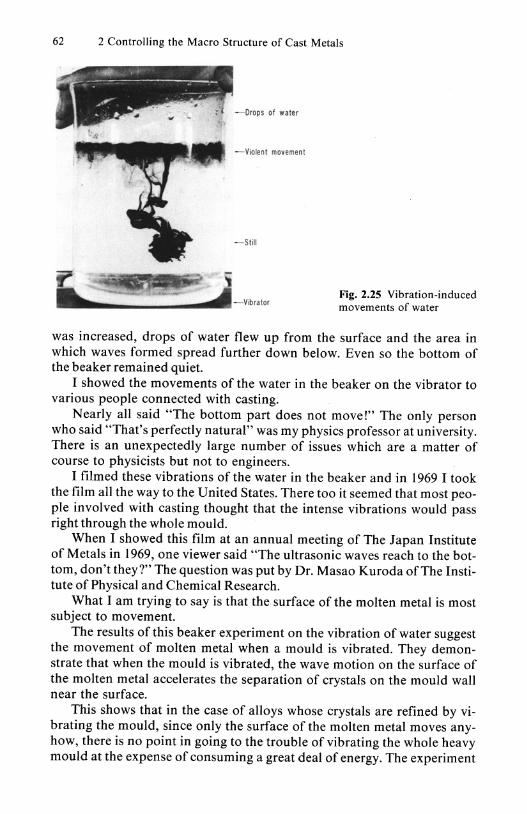
When drops of ink were placed on the surface and the beaker was vibrated, only the part near the surface moved violently, and the lower region hardly moved at all, as shown in Fig. 2.25. When the vibration energy
62 2 Controlling the Macro Structure of Cast Metals
-Drops of water
Violent movement
Still
Vibrator Fig. 2.25 Vibration-induced movements of water
was increased, drops of water flew up from the surface and the area in which waves formed spread further down below. Even so the bottom of the beaker remained quiet.
I showed the movements of the water in the beaker on the vibrator to various people connected with casting.
Nearly all said "The bottom part does not move!" The only person who said "That's perfectly natural" was my physics professor at university. There is an unexpectedly large number of issues which are a matter of course to physicists but not to engineers.
I filmed these vibrations of the water in the beaker and in 1969 I took the film all the way to the United States. There too it seemed that most people involved with casting thought that the intense vibrations would pass right through the whole mould.
When I showed this film at an annual meeting of The Japan Institute of Metals in 1969, one viewer said "The ultrasonic waves reach to the bottom, don't they?" The question was put by Dr. Masao Kuroda of The Institute of Physical and Chemical Research.
What I am trying to say is that the surface of the molten metal is most subject to movement.
The results of this beaker experiment on the vibration of water suggest the movement of molten metal when a mould is vibrated. They demonstrate that when the mould is vibrated, the wave motion on the surface of the molten metal accelerates the separation of crystals on the mould wall near the surface.
This shows that in the case of alloys whose crystals are refined by vibrating the mould, since only the surface of the molten metal moves anyhow, there is no point in going to the trouble of vibrating the whole heavy mould at the expense of consuming a great deal of energy. The experiment

2.1 Equiaxed Crystal Structure 63
teaches that we should contrive to move effectively only the area around the surface of the molten metal, using only a small amount of energy.
When I spoke about this at a lecture on casting to students in the Department of Mechanical Engineering at my university, I was asked "I was watching Tokyo Bay during a typhoon and the water became dirty. Doesn't this mean that the movement occurs right down to the bottom of the sea?" I replied "Tokyo Bay is just like a dish. The bottom of the deeper Pacific Ocean will not move."
It seems that even now many people believe that when vibrated, the molten metal in a deep mould will move easily right down to the bottom.
Accordingly, I observed23 the effect on the solid structure of the ingot when only the surface of the molten metal in the mould is moved deliberately.
'OX"" Pouring
Mould
6S
Fig. 2.26 Bottom-pouring mould and vibrator
I made a bottom-pouring mould as shown in Fig. 2.26, and set a ringshaped vibrator above this. After the molten metal poured in from below rose and came in contact with this vibrator, I vibrated the surface of the molten metal for just 10 seconds. In this case I used an AI-O.20/0Cu alloy, the pouring temperature was 680 0 C, and the vibrator was made to vibrate vertically at an amplitude of 0.2 mm 50 c/ s. Since it took 90 seconds for the whole metal to solidify, the vibration was for only a tiny period.
As Fig. 2.27 shows, merely vibrating the surface of the molten metal produced finer equiaxed crystals than in the non-vibrated ingot.
If vibration of the surface is important, care must also be taken over pouring operations.
Figure 2.28 shows a case in which the molten metal was poured into the center of a mould from a 16 mm-diameter hole in the bottom of the tundish. Merely by shifting the pouring hole to the mould wall side, the structure changed greatly, as shown in Fig. 2.29.

64 2 Controlling the Macro Structure of Cast Metals
(a) Non-vibrated (b) Vibrated
Fig. 2.27 Macro structure of AI-0.2%Cu alloy ingots cast at 680 °C by the bottom-pouring method. (a) Non-vibrated; (b) Vibrated
10
Fig. 2.28 Macro structure of an AI-0.2%Cu alloy ingot poured from the top at 680 ° C
Then I made six pouring holes with the sam section as before, as shown in Fig. 2.30, and caused the wave motion to concentrate around the surface. As you can see, the structure became even finer.
During casting experiments by students I always emphasize strongly that unless not only the pouring temperature, but also "the pouring position and the height of the pouring hole are standardized, it is useless to

~ iii ---- 16 ¢
10 , iii II'
d. ~~=~'"-
fa!
0 ~
f--65-
"
65
I
10
2.1 Equiaxed Crystal Structure 65
Fig. 2.29 Macro structure of an Al-0.2%Cu alloy ingot poured from the top at 680 0 C
Fig. 2.30 Macro structure of an AI-0.2%Cu alloy ingot poured from the top at 680 0 C
compare structures, since these factors have a major influence on the solidified structure."
Apparently it is not very widely known that the wave motion on the surface of the molten metal has such a major influence on the cast structure. This is because when the pouring temperature is high, the crystals that have separated from the mould wall melt again, and so the effect is not obvious. Lowering the pouring temperature, however, clearly brings out this effect.
66 2 Controlling the Macro Structure of Cast Metals
I am even concerned over whether or not the edges of the inside of the tundish nozzle in Fig.2.31 are smooth. Experience has shown me that if they are uneven, the molten metal that comes out pulsates, and this has a major effect on the solidified structure.
When I visited the University of Toronto in 1978, Professor A. McLean, who was studying tundish nozzles for use in continuous casting of steel, said "I thought it strange that no matter how uniform the pouring conditions were, the solidified structures of the steel ingots obtained were not uniform." No matter how uniform may be the pouring temperature and mould cooling conditions, unless the movements of the molten metal are also made uniform it is impossible to produce uniform solidified structures. Effective site for vibration.
Vibration acts particularly effectively in the formation of equiaxed crystals at the corners of the surface of the molten metal and the mould wall. Once crystals separate there, when they move along the mould wall they induce other crystals to separate, and crystal formation and separation proceed in a chain reaction.
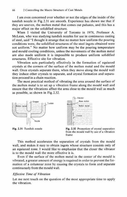
The most practical method of vibrating the area around the surface of the molten metal is to set up a vibration frame along the mould wall and ensure that the vibrations affect the area close to the mould wall as much as possible, as shown in Fig. 2.32.
Fig. 2.32 Promotion of crystal separation from the mould wall by use of a vibration frame
This method accelerates the separation of crystals from the mould wall, and makes it easy to obtain ingots whose structure consists only of an equiaxed zone. I would like to emphasize that the closer the vibrator is to the mould wall the more effective it is.
Even if the surface of the molten metal in the center of the mould is vibrated, a greater amount of energy is required in order to prevent the formation of a columnar zone by causing the crystals to form and separate continuously from the mould wall.
Effective Time of Vibration
Let me next touch on the question of the most appropriate time to apply the vibration.
2.1 Equiaxed Crystal Structure 67
(a) (b) (e) (d)
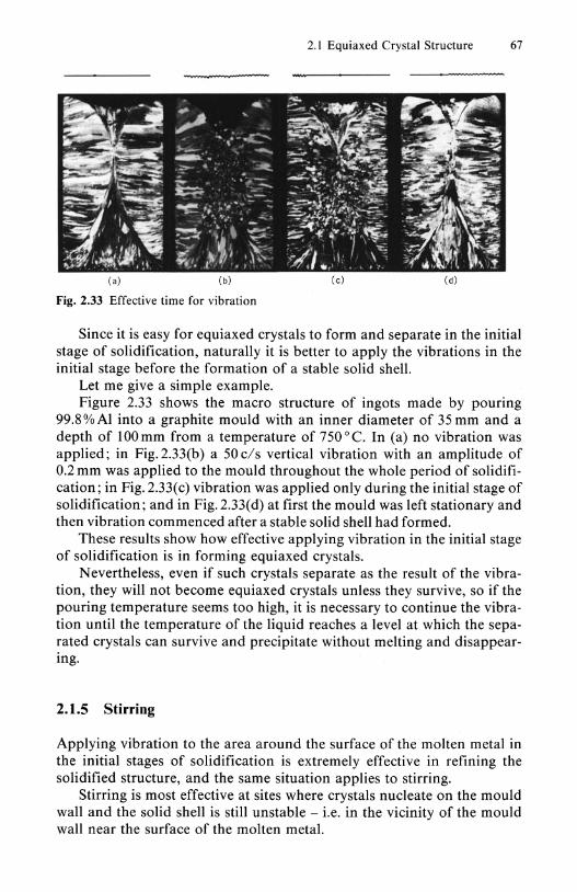
Fig. 2.33 Effective time for vibration
Since it is easy for equiaxed crystals to form and separate in the initial stage of solidification, naturally it is better to apply the vibrations in the initial stage before the formation of a stable solid shell.
Let me give a simple example. Figure 2.33 shows the macro structure of ingots made by pouring
99.8 % Al into a graphite mould with an inner diameter of 35 mm and a depth of 100mm from a temperature of 750°C. In (a) no vibration was applied; in Fig. 2.33(b) a 50 c/ s vertical vibration with an amplitude of 0.2 mm was applied to the mould throughout the whole period of solidification; in Fig. 2.33( c) vibration was applied only during the initial stage of solidification; and in Fig. 2.33( d) at first the mould was left stationary and then vibration commenced after a stable solid shell had formed.
These results show how effective applying vibration in the initial stage of solidification is in forming equiaxed crystals.
Nevertheless, even if such crystals separate as the result of the vibration, they will not become equiaxed crystals unless they survive, so if the pouring temperature seems too high, it is necessary to continue the vibration until the temperature of the liquid reaches a level at which the separated crystals can survive and precipitate without melting and disappearing.
2.1.5 Stirring
Applying vibration to the area around the surface of the molten metal in the initial stages of solidification is extremely effective in refining the solidified structure, and the same situation applies to stirring.
Stirring is most effective at sites where crystals nucleate on the mould wall and the solid shell is still unstable - i.e. in the vicinity of the mould wall near the surface of the molten metal.
68 . 2 Controlling the Macro Structure of Cast Metals
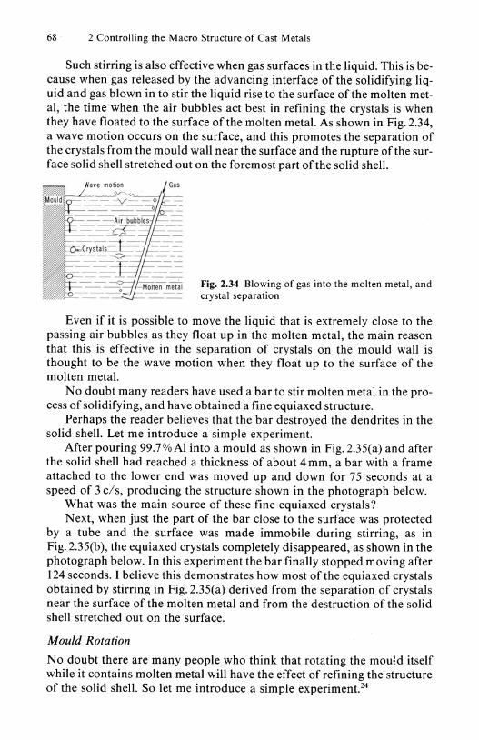
Such stirring is also effective when gas surfaces in the liquid. This is because when gas released by the advancing interface of the solidifying liquid and gas blown in to stir the liquid rise to the surface of the molten metal, the time when the air bubbles act best in refining the crystals is when they have floated to the surface of the molten metal. As shown in Fig. 2.34, a wave motion occurs on the surface, and this promotes the separation of the crystals from the mould wall near the surface and the rupture of the surface solid shell stretched out on the foremost part of the solid shell.
Fig. 2.34 Blowing of gas into the molten metal, and crystal separation
Even if it is possible to move the liquid that is extremely close to the passing air bubbles as they float up in the molten metal, the main reason that this is effective in the separation of crystals on the mould wall is thought to be the wave motion when they float up to the surface of the molten metal.
No doubt many readers have used a bar to stir molten metal in the process of solidifying, and have obtained a fine equiaxed structure.
Perhaps the reader believes that the bar destroyed the dendrites in the solid shell. Let me introduce a simple experiment.
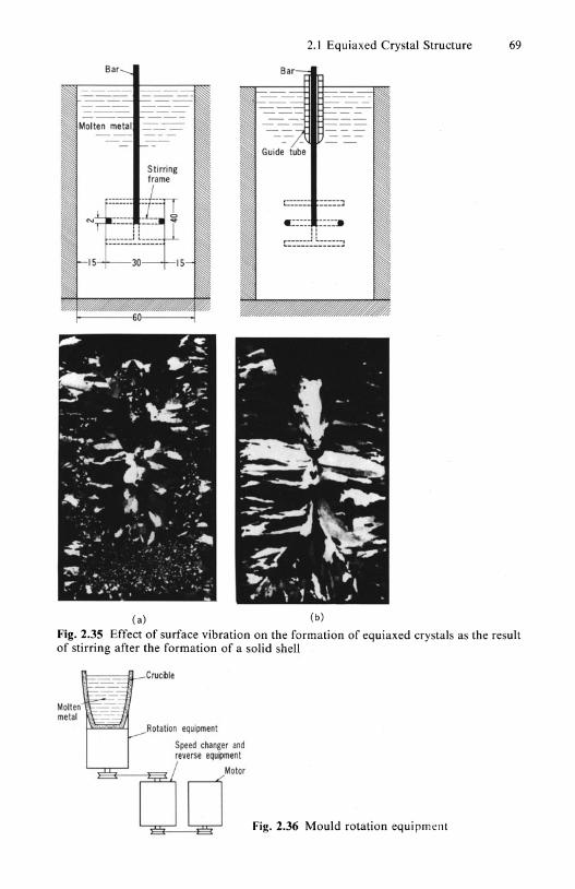
After pouring 99.7% Al into a mould as shown in Fig. 2.35(a) and after the solid shell had reached a thickness of about 4 mm, a bar with a frame attached to the lower end was moved up and down for 75 seconds at a speed of 3 cis, producing the structure shown in the photograph below.
What was the main source of these fine equiaxed crystals? N ext, when just the part of the bar close to the surface was protected
by a tube and the surface was made immobile during stirring, as in Fig. 2.35(b), the equiaxed crystals completely disappeared, as shown in the photograph below. In this experiment the bar finally stopped moving after 124 seconds. I believe this demonstrates how most of the equiaxed crystals obtained by stirring in Fig. 2.35(a) derived from the separation of crystals near the surface of the molten metal and from the destruction of the solid shell stretched out on the surface.
Mould Rotation
No doubt there are many people who think that rotating the mou~d itself while it contains molten metal will have the effect of refining the structure of the solid shell. So let me introduce a simple experiment.24
Bar-...
---- -----==- -- =--=: =--
Molten metal
Stirring frame
,------- -i-on E------ -----N ----- - -- Si!
-----1 I ----.. HS ------~~=+_15-
Ca)
2.1 Equiaxed Crystal Structure 69
Bar
Guide tube
,.------- ----"'t "'------ -----~
«::::- ::::-. " "
~::-::.:--::::::-.:
Cb)
Fig_ 2_35 Effect of surface vibration on the formation of equiaxed crystals as the result of stirring after the formation of a solid shell
Molten metal
\'I---....[,l_ Crucible
Rotation equipment
Speed changer and reverse eQu"ment
Motor
Fig. 2.36 Mould rotation equipment

70 2 Controlling the Macro Structure of Cast Metals
When a graphite crucible used as the mould was set on a turntable as in Fig. 2.36 and 99.7%Al was poured into it from no°c, the macro structure of the ingots consisted largely of columnar crystals, as shown in Fig.2.37. Next, rotation at a speed of 200r.p.m. was commenced immediately after pouring the molten metal into the mould. The structures obtained when rotation was ceased after 10 seconds, 30 seconds and upon completion of the solidification - i.e. after 180 seconds of rotation - were as shown in Fig. 2.37(b), (c) and (d).
The earlier rotation ceased after the commencement of solidification, the finer was the structure. This result shows that the waves on the surface when rotation ceases affect the formation of equiaxed crystals, and that the more instable is the solid shell the more intense is this effect.
In Fig.2.38(a) molten metal was poured into a mould rotating at 200 r.p.m., and every 5 seconds the rotation of the mould was ceased. In this case it was observed that the surface shook constantly, revealing that
(a)
(e)
Fig.2.37 99.7%AI in which mould rotation stirring was carried out. (a) Standing; (b) 200 r.p.m. for 10 sees.; (c) 30 sees.; (d) 180 sees

2.1 Equiaxed Crystal Structure 71
(a) (b)
Fig. 2.38 Effect of mould rotation on the solidified structure. (a) When intermittent rotation was carried out at 200 r.p.m. for 5 seconds at a time (b) When rotation was commenced 10 seconds after pouring
this shaking was effective in forming equiaxed crystals. By contrast, in Fig.2.38(b) the mould was left for 10 seconds after pouring, and rotation commenced after the stable solid shell had been given an opportunity to form. Here few fine equiaxed crystals were observed.
I believe that this suggests that even if rotation is carried out, after a stable solid shell has formed on the mould wall only part of the thin solid shell stretched out on the surface will be destroyed by the wave motion when the rotation commences, and so rotation does not act effectively in separating equiaxed crystals from the stable solid shell.
Electromagnetic Stirring
It is a well-known fact that electromagnetic stirring is the most practical and useful method for refining the cast structure of continuously-cast ingots. It seems to me, however, that a mistaken interpretation of how electromagnetic stirring causes refining is widespread.
Apparently there is a belief that since the molten metal moves as the result of the electromagnetic stirring, the branches of the dendrites in the foremost part of the solid shell melt again and separate and form independent equiaxed crystals.
Crystals form a solid shell on the mould wall and grow. I have repeatedly stated that crystals separate from the mould wall in the stage prior to the formation of the solid shell. If electromagnetic stirring takes place at this time, firstly it will prevent the formation of a solid shell and accelerate the separation of the crystals from the mould wall.
Is it such an easy matter to destroy the front part of the solid shell formed by overcoming the effect of such stirring? If the stirring is so strong
72 2 Controlling the Macro Structure of Cast Metals
Pouring mouth
H eating element
=ta.JlllO:=---,Cooling water
Electric wire
""'-__ Stainless steel
;::~===~=i;--IFire bricks
Receiving tan,
Fig. 2.39 Electromagnetic rotary-stirring device
that the necked-shape branches partially remelt, why do the crystals not separate from the root prior to the formation of the stable solid shell?
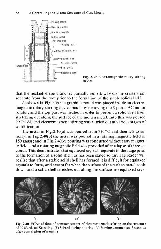
As shown in Fig. 2.39,25 a graphite mould was placed inside an electromagnetic rotary-stirring device made by removing the 3-phase AC motor rotator, and the top part was heated in order to prevent a solid shell from stretching out along the surface of the molten metal. Into this was poured 99.70/0 AI, and electromagnetic stirring was carried out at various stages of solidification.
The metal in Fig.2.40(a) was poured from 750°C and then left to solidify; in Fig. 2.40(b) the metal was poured in a rotating magnetic field of 150 gauss; and in Fig. 2.40( c) pouring was conducted without any magnetic field, and a rotating magnetic field was provided after a lapse of three seconds. This demonstrates that equiaxed crystals separate in the stage prior to the formation of a solid shell, as has been stated so far. The reader will realize that after a stable solid shell has formed it is difficult for equiaxed crystals to form, and except for when the surface of the molten metal cools down and a solid shell stretches out along the surface, no equiaxed crys-
(a) (b) (e)
Fig. 2.40 Effect of time of commencement of electromagnetic stirring on the structure of 99.8%AI. (a) Standing; (b) Stirred during pouring; (c) Stirring commenced 3 seconds after completion of pouring

2.1 Equiaxed Crystal Structure 73
tals can be obtained from the solid shell even if electromagnetic stirring is carried out.
However, many people actually involved in continuous casting of ingots say "Since the solid shell forms instantaneously after pouring, it is inconceivable that there is any opportunity for equiaxed crystals to separate from the mould wall."
I have examined numerous steel ingots cast continuously. In continuous casting, occasionally a phenomenon called breakout occurs whereby part of the thin solid shell breaks and the unsolidified molten metal inside flows out. In such cases, the state of the formation of the stable solid shell can be learnt from the configuration of the uppermost part of the remaining solid shell.
Fig. 2.41 Upper part of a continuously-cast carbon steel ingot that broke out
Figure 2.41 is a typical example of the top of a solid shell obtained in a carbon steel ingot. It shows that near the surface the solid shell has not formed uniformly, and that this part was in an unstable stage. In cases in which the solid shell on the upper part is uniformly formed horizontally, I do not think that equiaxed crystals could be obtained even if electromagnetic stirring was carried out. However, frequently I have been asked "When steel ingots are produced by continuous casting, a solid shell forms instantaneously on the mould wall, and the upper end of the solid is smooth, whereas in some cases equiaxed crystals are produced by electromagnetic stirring. Why is this?"
Since I am talking about cases in which molten metal is merely poured into a mould, in cases such as in continuous casting, when there is a refractory immersed nozzle on the surface or a cold covering material is added to the surface or the surface is stirred with an iron bar so as to prevent floatage, "the surface of the immersed nozzle, covering material or iron bar becomes a source for the formation and separation of equiaxed crystals", as I have said so far. If such separated crystals exist, naturally the crystal mul-

74 2 Controlling the Macro Structure of Cast Metals
tiplication effect will be promoted by electromagnetic stirring. Here, however, I am discussing the typical case in which nothing such as a surface covering material exists - i.e. the case in which the molten metal merely exists within the mould.
In order to demonstrate that the type of electromagnetic stirring which can be expected to be most effective is stirring near the surface of the molten metal, I poured Al molten metal into a long cylindrical graphite mould and ensured that electromagnetic stirring was concentrated in the lower and upper parts. As shown in Fig. 2.42, the results illustrated clearly that stirring the upper part is more effective.
Frequently I have also been asked "When I poured molten metal into a mould and stirred the lower part of the mould electromagnetically after a stable solid shell had formed, I obtained ingots having a larger equiaxed zone than when electromagnetic stirring was not carried out. Why is this?" This is because the crystals that had separated from the mould wall prior to the formation of the stable solid shell and that were floating in the molten metal multiply through electromagnetic stirring.
Except for pure metals, I think that in actual casting it would be difficult to form a stable solid shell without allowing the separation of any crystals at all from the mould wall during pouring. If such crystals that have se-
Fig. 2.42 Effect of the electromagnetic stirring position on the solidified structure of 99.8%AI

Transparent container
Ammonium chloride aqueous solution model
Cooling water
Direction of flow
Immediately after commencement of stirring (a)
Prior to commencement of stirring (b)
2.1 Equiaxed Crystal Structure 75
Fig. 2.43 Stirring device in ammonium chloride aqueous solution model
Separate
After stirring
(d)
Fig. 2.44 Effect of stirring on the solidification of an ammonium chloride aqueous solution model. (a) Prior to formation of stable solid shell; (b) After formation of stable solid shell; (c) When separated crystals exist; (d) Figure explaining the hammering phenomenon
76 2 Controlling the Macro Structure of Cast Metals
parated from the mould wall exist in the liquid before electromagnetic stirring commences, electromagnetic stirring will cause them to multiply rapidly and form a fine equiaxed zone.
Crystal multiplication caused by electromagnetic stirring firstly requires that free crystals exist within the liquid. In order to clarify this, 125
used an ammonium chloride aqueous solution model to observe solidification at the time of stirring.
Figure 2.43 shows a transparent container made of acrylic resin plate, inside which is a propeller. Water-cooling equipment is attached at the bottom, and the ammonium chloride model in the container is cooled from below upwards, so that the crystals grow in an upwards direction.
The reason that we cooled the container from the bottom in particular and not from the sides is that if cooled from the sides the crystals that appear on the side walls separate and float within the liquid. When cooled from the bottom, crystals nucleated on the botton, and grew preferentially along the bottom, as in Fig. 2.44(a). When the propeller was rotated before these crystals spread over the whole bottom, the hotter solution above was brought down and the crystals melted from the surface, and finally separated from the bottom of the container.
Next when the propeller was rotated in the stage when the stable solid shell was forming over the whole bottom of the container and growing upwards, the dendrites merely melted from the front and contracted, as in Fig. 2.44(b), and the branches did not fly off. Next I deliberately ensured that the crystals separated from the side walls. It was observed that some of these adhered to the front of the dendrites and that the crystals sedimented there were destroyed, as shown in Figs. 2.44( c) and (d).
Hammering
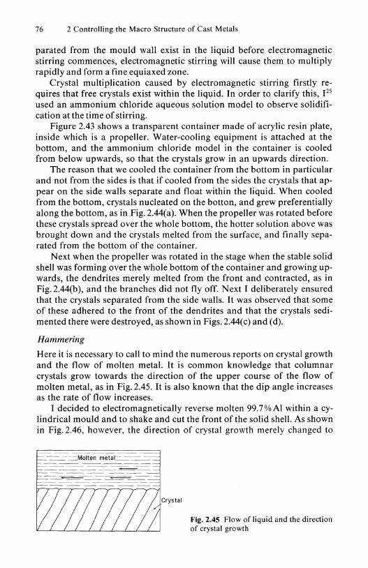
Here it is necessary to call to mind the numerous reports on crystal growth and the flow of molten metal. It is common knowledge that columnar crystals grow towards the direction of the upper course of the flow of molten metal, as in Fig. 2.45. It is also known that the dip angle increases as the rate of flow increases.
I decided to electromagnetically reverse molten 99.7% Al within a cylindrical mould and to shake and cut the front of the solid shell. As shown in Fig. 2.46, however, the direction of crystal growth merely changed to
-==-:=-:-=Molten metal=-=-:=--
Fig. 2.45 Flow of liquid and the direction of crystal growth
2.1 Equiaxed Crystal Structure 77
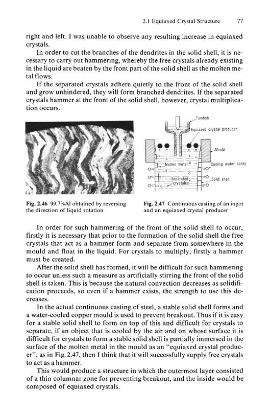
right and left. I was unable to observe any resulting increase in equiaxed crystals.
In order to cut the branches of the dendrites in the solid shell, it is necessary to carry out hammering, whereby the free crystals already existing in the liquid are beaten by the front part of the solid shell as the molten metal flows.
If the separated crystals adhere quietly to the front of the solid shell and grow unhindered, they will form branched dendrites. If the separated crystals hammer at the front of the solid shell, however, crystal multiplication occurs.
Fig. 2.46 99.7%Al obtained by reversing the direction of liquid rotation
Fig. 2.47 Continuous casting of an ingot and an equiaxed crystal producer
In order for such hammering of the front of the solid shell to occur, firstly it is necessary that prior to the formation of the solid shell the free crystals that act as a hammer form and separate from somewhere in the mould and float in the liquid. For crystals to multiply, firstly a hammer must be created.
After the solid shell has formed, it will be difficult for such hammering to occur unless such a measure as artificially stirring the front of the solid shell is taken. This is because the natural convection decreases as solidification proceeds, so even if a hammer exists, the strength to use this decreases.
In the actual continuous casting of steel, a stable solid shell forms and a water-cooled copper mould is used to prevent breakout. Thus if it is easy for a stable solid shell to form on top of this and difficult for crystals to separate, if an object that is cooled by the air and on whose surface it is difficult for crystals to form a stable solid shell is partially immersed in the surface of the molten metal in the mould as an "equiaxed crystal producer", as in Fig. 2.47, then I think that it will successfully supply free crystals to act as a hammer.
This would produce a structure in which the outermost layer consisted of a thin columnar zone for preventing breakout, and the inside would be composed of equiaxed crystals.
78 2 Controlling the Macro Structure of Cast Metals
2.1.6 Pouring Temperature
Based on the crystal separation theory, so far we have discussed how to produce many equiaxed crystals. Ultimately this boils down to the question of how to form and separate many crystals from the mould wall, or how to make the separated crystals survive.
Since the survival of the separated crystals depends on the pouring temperature, a low pouring temperature is vital.
If the pouring temperature is lowered, however, the flow of the molten metal worsens, and inclusions caught up inside will not float to the surface.
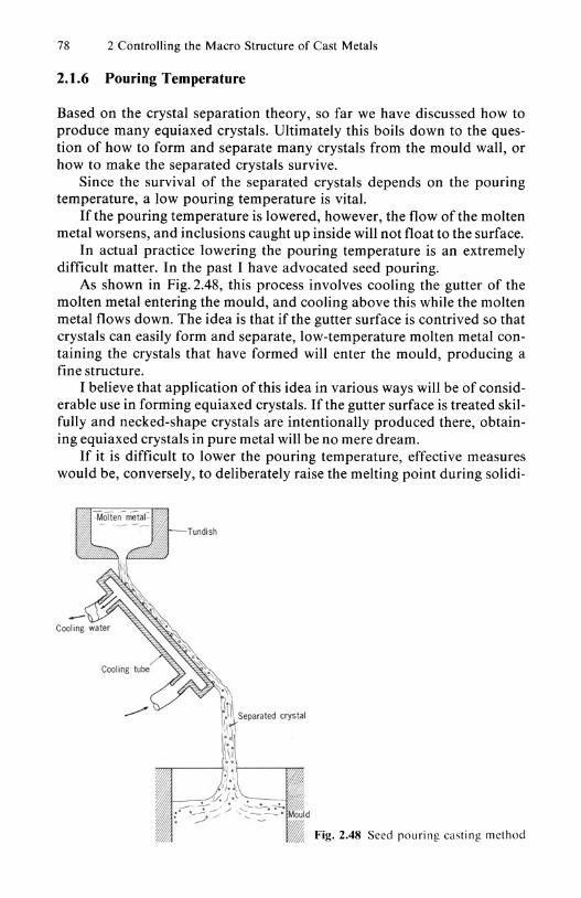
In actual practice lowering the pouring temperature is an extremely difficult matter. In the past I have advocated seed pouring.
As shown in Fig. 2.48, this process involves cooling the gutter of the molten metal entering the mould, and cooling above this while the molten metal flows down. The idea is that if the gutter surface is contrived so that crystals can easily form and separate, low-temperature molten metal containing the crystals that have formed will enter the mould, producing a fine structure.
I believe that application of this idea in various ways will be of considerable use in forming equiaxed crystals. If the gutter surface is treated skilfully and necked-shape crystals are intentionally produced there, obtaining equiaxed crystals in pure metal will be no mere dream.
If it is difficult to lower the pouring temperature, effective measures would be, conversely, to deliberately raise the melting point during solidi-
Fig. 2.48 Seed pouring casting method
2.2 Columnar Structure 79
fication of the molten metal poured into the mould by the use of additives, or to use addition-agents that enable internal cooling.
2.2 Columnar Structure
So far we have discussed how to produce equiaxed crystals or a fine structure.
Let us now move on to a completely opposite discussion of how not to produce equiaxed crystals, or how to produce a structure consisting of columnar crystals alone.
Since the reader has learnt the mechanism of the formation of equiaxed crystals, I feel that he will be aware of how not to produce them, but I will touch on this matter in any case.
In order to obtain columnar crystals, it is necessary firstly to form a stable solid shell on the mould wall and to prevent separation of crystals from the mould wall. It is also important to minimize as much as possible impurities that will constrict the root of the crystals.
In order to create a stable solid shell in the given alloy, it is necessary to use a quenching mould and ensure that a solid shell can form there as swiftly as possible.
Since there is a danger of crystal separation if the mould wall is rough, the mould wall must be as smooth as possible. Methods must be devised so that the molten metal does not shake within the mould and so that a stable shell can form quietly.
If the pouring temperature is raised and any crystals that may have separated from the mould wall in the intitial stage of solidification are melted and made to disappear, it is possible to obtain a structure consisting only of columnar crystals and having no equiaxed crystals.
2.2.1 Unidirectional Solidification
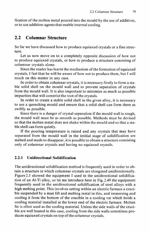
The unidirectional solidification method is frequently used in order to obtain a structure in which columnar crystals are elongated unidirectionally. Figure 2.3 showed the equipment I used in the unidirectional solidification of an AI-Ti alloy, so let me introduce here in Fig. 2.49 the equipment frequently used in the unidirectional solidification of steel alloys with a high melting point. This involves setting within an electric furnace a crucible suspended by a man lift and melting metal in this, and immersing and cooling it from the bottom of the crucible in a cooling vat which holds a cooling material installed at the lower end of the electric furnace. Molten Sn is often used as the cooling material. Unless the side walls of the crucible are well heated in this case, cooling from the side walls sometimes produces equiaxed crystals on top of the columnar crystals.

80 2 Controlling the Macro Structure of Cast Metals
Crucible
Heating furnace
Heating element
Cooling val Fig. 2.49 Example of vertical unidirectional solidification equipment
When I gave a lecture at the Xian Jiatong University in China in 1982, I was asked "Even though I heated the side walls of a container in an electric furnace and cooled it unidirectionally from below, the ingots obtained had equiaxed crystals on top of the columnar crystals. How can this be explained by the separation theory?" I am often asked similar questions.
It seems that there is a tendency to jump to the conclusion that if the side walls of the mould are heated, crystals will not form and separate from the side walls. When I am asked such a question, I reply "Poor experiment ! Your experimental method was inappropriate."
Figure 2.50 shows a unidirectionally solidified structure obtained by cooling an AI-O.l3 % Ti alloy from the lower end. Equiaxed crystals appeared on the upper part as in (a). Next, when a heating element was placed as close as possible to the outside of the crucible so as to prevent
(a) ( b)
Fig. 2.50 Unidirectionally solidified AI-0.13%Ti alloy ingot. (a) Columnar crystals and equiaxed crystals; (b) Perfect columnar crystals
2.2 Columnar Structure 81
<al (b) (e)
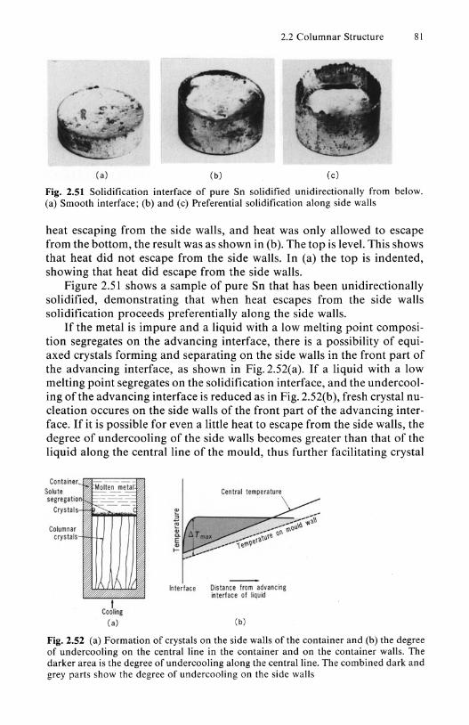
Fig. 2.51 Solidification interface of pure Sn solidified unidirectionally from below. (a) Smooth interface; (b) and (c) Preferential solidification along side walls
heat escaping from the side walls, and heat was only allowed to escape from the bottom, the result was as shown in (b). The top is level. This shows that heat did not escape from the side walls. In (a) the top is indented, showing that heat did escape from the side walls.
Figure 2.51 shows a sample of pure Sn that has been unidirectionally solidified, demonstrating that when heat escapes from the side walls solidification proceeds preferentially along the side walls.
If the metal is impure and a liquid with a low melting point composition segregates on the advancing interface, there is a possibility of equiaxed crystals forming and separating on the side walls in the front part of the advancing interface, as shown in Fig.2.S2(a). If a liquid with a low melting point segregates on the solidification interface, and the undercooling of the advancing interface is reduced as in Fig. 2.S2(b), fresh crystal nucleation occures on the side walls of the front part of the advancing interface. If it is possible for even a little heat to escape from the side walls, the degree of undercooling of the side walls becomes greater than that of the liquid along the central line of the mould, thus further facilitating crystal
Container Solute segregatio
Cr~stals
Columnar cr,stals
n ~e~~ ~ .-,-::: ~---
1/\ I,
I Cooling
Centrat temperature
klterface Oi.tance from advancing interface of liquid
<al (b)
Fig. 2.52 (a) Formation of crystals on the side walls of the container and (b) the degree of undercooling on the central line in the container and on the container walls. The darker area is the degree of under cooling along the central line. The combined dark and grey parts show the degree of undercooling on the side walls

82 2 Controlling the Macro Structure of Cast Metals
nucleation on the side walls of the front part of the advancing interface, as shown by the dotted line.
It is possible to produce ingots having absolutely no equiaxed crystals. If during solidification the temperature of the side walls in contact with the advancing interface is always maintained above the crystallization temperature of the alloy's primary crystals and the alloy is made to solidify unidirectionally, it is possible to obtain ingots whose structure consists only of columnar crystals, with absolutely no equiaxed crystals. Using this principle, I have developed a new continuous casting process, the O.C.c. process, which continuously casts long ingots having a unidirectionally solidified structure only and absolutely no equiaxed crystals.
I will discuss this in detail in the next section on "Application of the separation theory".