Solidification Behavior and Detection of Hotspots in Aluminium Alloy
12
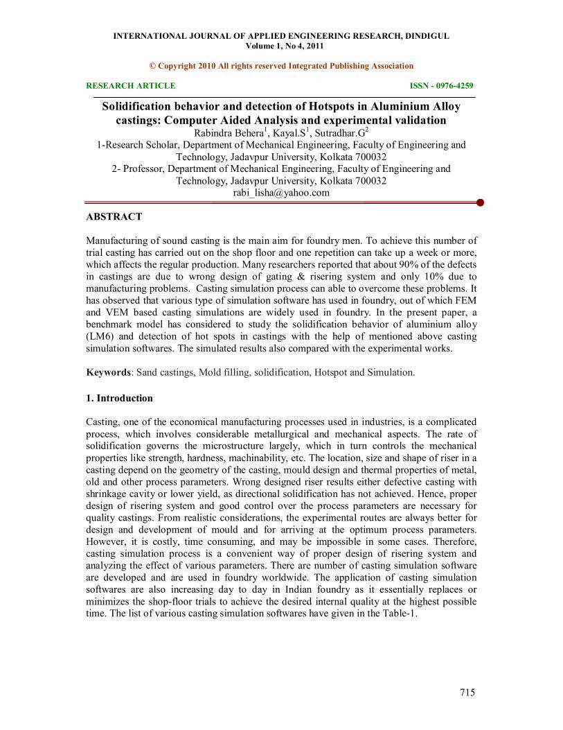
INTERNATIONAL JOURNAL OF APPLIED ENGINEERING RESEARCH, DINDIGUL Volume 1, No 4, 2011 © Copyright 2010 All rights reserved Integrated Publishing Association RESEARCH ARTICLE ISSN 09764259 715 Solidification behavior and detection of Hotspots in Aluminium Alloy castings: Computer Aided Analysis and experimental validation Rabindra Behera 1 , Kayal.S 1 , Sutradhar.G 2 1Research Scholar, Department of Mechanical Engineering, Faculty of Engineering and Technology, Jadavpur University, Kolkata 700032 2 Professor, Department of Mechanical Engineering, Faculty of Engineering and Technology, Jadavpur University, Kolkata 700032 [email protected] ABSTRACT Manufacturing of sound casting is the main aim for foundry men. To achieve this number of trial casting has carried out on the shop floor and one repetition can take up a week or more, which affects the regular production. Many researchers reported that about 90% of the defects in castings are due to wrong design of gating & risering system and only 10% due to manufacturing problems. Casting simulation process can able to overcome these problems. It has observed that various type of simulation software has used in foundry, out of which FEM and VEM based casting simulations are widely used in foundry. In the present paper, a benchmark model has considered to study the solidification behavior of aluminium alloy (LM6) and detection of hot spots in castings with the help of mentioned above casting simulation softwares. The simulated results also compared with the experimental works. Keywords: Sand castings, Mold filling, solidification, Hotspot and Simulation. 1. Introduction Casting, one of the economical manufacturing processes used in industries, is a complicated process, which involves considerable metallurgical and mechanical aspects. The rate of solidification governs the microstructure largely, which in turn controls the mechanical properties like strength, hardness, machinability, etc. The location, size and shape of riser in a casting depend on the geometry of the casting, mould design and thermal properties of metal, old and other process parameters. Wrong designed riser results either defective casting with shrinkage cavity or lower yield, as directional solidification has not achieved. Hence, proper design of risering system and good control over the process parameters are necessary for quality castings. From realistic considerations, the experimental routes are always better for design and development of mould and for arriving at the optimum process parameters. However, it is costly, time consuming, and may be impossible in some cases. Therefore, casting simulation process is a convenient way of proper design of risering system and analyzing the effect of various parameters. There are number of casting simulation software are developed and are used in foundry worldwide. The application of casting simulation softwares are also increasing day to day in Indian foundry as it essentially replaces or minimizes the shopfloor trials to achieve the desired internal quality at the highest possible time. The list of various casting simulation softwares have given in the Table1.
-
Upload
jpmanikandan -
Category
Documents
-
view
229 -
download
0
description
Casting Simulation
Transcript of Solidification Behavior and Detection of Hotspots in Aluminium Alloy
INTERNATIONAL JOURNAL OF APPLIED ENGINEERING RESEARCH, DINDIGUL Volume 1, No 4, 2011
© Copyright 2010 All rights reserved Integrated Publishing Association
RESEARCH ARTICLE ISSN 09764259
715
Solidification behavior and detection of Hotspots in Aluminium Alloy castings: Computer Aided Analysis and experimental validation
Rabindra Behera 1 , Kayal.S 1 , Sutradhar.G 2 1Research Scholar, Department of Mechanical Engineering, Faculty of Engineering and
Technology, Jadavpur University, Kolkata 700032 2 Professor, Department of Mechanical Engineering, Faculty of Engineering and
Technology, Jadavpur University, Kolkata 700032 [email protected]
ABSTRACT
Manufacturing of sound casting is the main aim for foundry men. To achieve this number of trial casting has carried out on the shop floor and one repetition can take up a week or more, which affects the regular production. Many researchers reported that about 90% of the defects in castings are due to wrong design of gating & risering system and only 10% due to manufacturing problems. Casting simulation process can able to overcome these problems. It has observed that various type of simulation software has used in foundry, out of which FEM and VEM based casting simulations are widely used in foundry. In the present paper, a benchmark model has considered to study the solidification behavior of aluminium alloy (LM6) and detection of hot spots in castings with the help of mentioned above casting simulation softwares. The simulated results also compared with the experimental works.
Keywords: Sand castings, Mold filling, solidification, Hotspot and Simulation.
1. Introduction
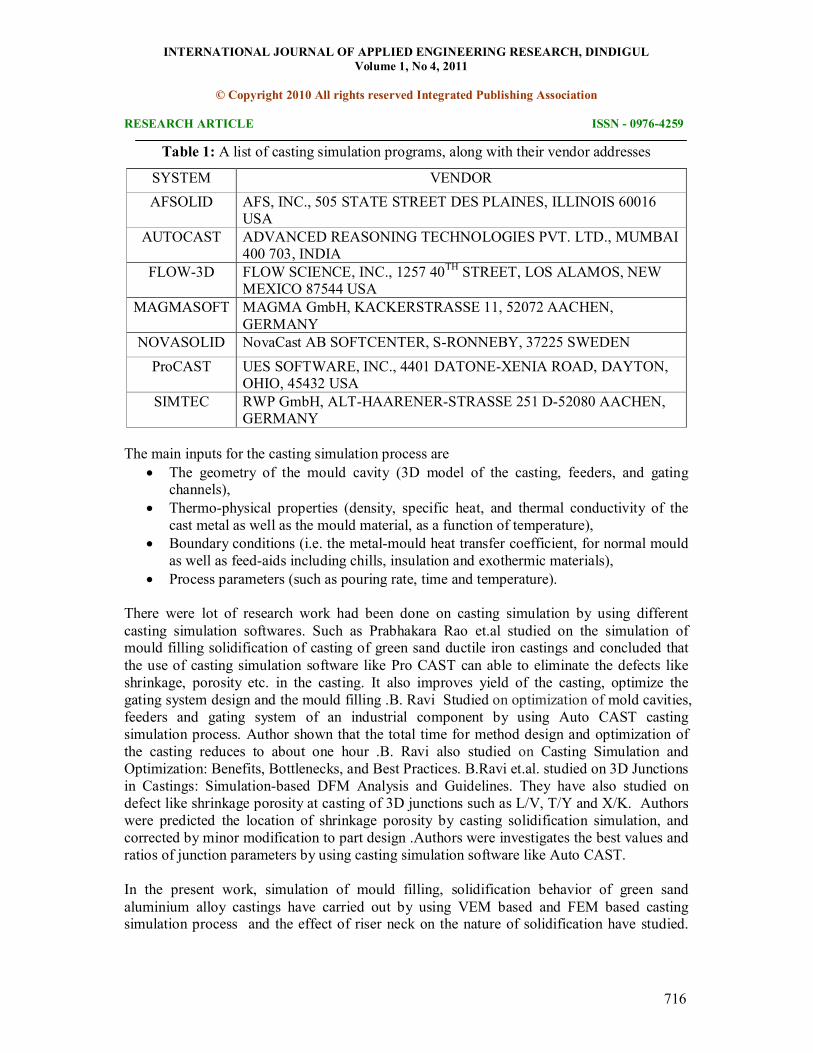
Casting, one of the economical manufacturing processes used in industries, is a complicated process, which involves considerable metallurgical and mechanical aspects. The rate of solidification governs the microstructure largely, which in turn controls the mechanical properties like strength, hardness, machinability, etc. The location, size and shape of riser in a casting depend on the geometry of the casting, mould design and thermal properties of metal, old and other process parameters. Wrong designed riser results either defective casting with shrinkage cavity or lower yield, as directional solidification has not achieved. Hence, proper design of risering system and good control over the process parameters are necessary for quality castings. From realistic considerations, the experimental routes are always better for design and development of mould and for arriving at the optimum process parameters. However, it is costly, time consuming, and may be impossible in some cases. Therefore, casting simulation process is a convenient way of proper design of risering system and analyzing the effect of various parameters. There are number of casting simulation software are developed and are used in foundry worldwide. The application of casting simulation softwares are also increasing day to day in Indian foundry as it essentially replaces or minimizes the shopfloor trials to achieve the desired internal quality at the highest possible time. The list of various casting simulation softwares have given in the Table1.
INTERNATIONAL JOURNAL OF APPLIED ENGINEERING RESEARCH, DINDIGUL Volume 1, No 4, 2011
© Copyright 2010 All rights reserved Integrated Publishing Association
RESEARCH ARTICLE ISSN 09764259
716
Table 1: A list of casting simulation programs, along with their vendor addresses
SYSTEM VENDOR AFSOLID AFS, INC., 505 STATE STREET DES PLAINES, ILLINOIS 60016
USA AUTOCAST ADVANCED REASONING TECHNOLOGIES PVT. LTD., MUMBAI
400 703, INDIA FLOW3D FLOW SCIENCE, INC., 1257 40 TH STREET, LOS ALAMOS, NEW
MEXICO 87544 USA MAGMASOFT MAGMA GmbH, KACKERSTRASSE 11, 52072 AACHEN,
GERMANY NOVASOLID NovaCast AB SOFTCENTER, SRONNEBY, 37225 SWEDEN ProCAST UES SOFTWARE, INC., 4401 DATONEXENIA ROAD, DAYTON,
OHIO, 45432 USA SIMTEC RWP GmbH, ALTHAARENERSTRASSE 251 D52080 AACHEN,
GERMANY
The main inputs for the casting simulation process are • The geometry of the mould cavity (3D model of the casting, feeders, and gating
channels), • Thermophysical properties (density, specific heat, and thermal conductivity of the
cast metal as well as the mould material, as a function of temperature), • Boundary conditions (i.e. the metalmould heat transfer coefficient, for normal mould
as well as feedaids including chills, insulation and exothermic materials), • Process parameters (such as pouring rate, time and temperature).
There were lot of research work had been done on casting simulation by using different casting simulation softwares. Such as Prabhakara Rao et.al studied on the simulation of mould filling solidification of casting of green sand ductile iron castings and concluded that the use of casting simulation software like Pro CAST can able to eliminate the defects like shrinkage, porosity etc. in the casting. It also improves yield of the casting, optimize the gating system design and the mould filling .B. Ravi Studied on optimization of mold cavities, feeders and gating system of an industrial component by using Auto CAST casting simulation process. Author shown that the total time for method design and optimization of the casting reduces to about one hour .B. Ravi also studied on Casting Simulation and Optimization: Benefits, Bottlenecks, and Best Practices. B.Ravi et.al. studied on 3D Junctions in Castings: Simulationbased DFM Analysis and Guidelines. They have also studied on defect like shrinkage porosity at casting of 3D junctions such as L/V, T/Y and X/K. Authors were predicted the location of shrinkage porosity by casting solidification simulation, and corrected by minor modification to part design .Authors were investigates the best values and ratios of junction parameters by using casting simulation software like Auto CAST.
In the present work, simulation of mould filling, solidification behavior of green sand aluminium alloy castings have carried out by using VEM based and FEM based casting simulation process and the effect of riser neck on the nature of solidification have studied.
INTERNATIONAL JOURNAL OF APPLIED ENGINEERING RESEARCH, DINDIGUL Volume 1, No 4, 2011
© Copyright 2010 All rights reserved Integrated Publishing Association
RESEARCH ARTICLE ISSN 09764259
717
Author also detects the level of porosity, location of hotspot and rate of solidification of metal with respect to time.
2. Objective computer modeling of solidification of castings
Many computer simulation programs now exist, but some require computers of a power not generally available to practical foundry men, while others take an unacceptably long time to obtain meaningful results. The aim of computer modeling is to:
• Predict the pattern of solidification, indicating where shrinkage cavities and associated defects may arise.
• Simulate solidification with the casting in various positions, so that the optimum position may be selected.
• Calculate the volumes and weights of all the different materials in the solid model. • Provide a choice of quality levels, allowing, for example, the highlighting or
ignoring of microporosity. • Perform over a range of metals, including steel, white iron, grey iron and ductile
iron and nonferrous metals.
3. Numerical simulation of solidification
The numerical simulation of solidification involves the following steps
a. Formulation of an accurate mathematical model of the solidification process
b. Specifying accurate values for thermal properties of material involved.
c. Performing the analysis to obtain the temperature history of casting and mould points.
d. Post processing the results to visualize the solidification the solidification pattern and
identify defects in the casting
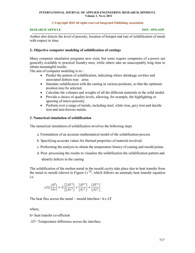
The solidification of the molten metal in the mould cavity take place due to heat transfer from the metal to mould (shown in Figure1) [9] , which follows an unsteady heat transfer equation i.e.
The heat flux across the metal – mould interface= h x ∆T
where,
h= heat transfer coefficient
∆T= Temperature difference across the interface.
INTERNATIONAL JOURNAL OF APPLIED ENGINEERING RESEARCH, DINDIGUL Volume 1, No 4, 2011
© Copyright 2010 All rights reserved Integrated Publishing Association
RESEARCH ARTICLE ISSN 09764259
718
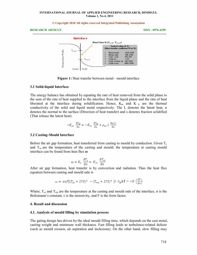
Figure 1: Heat transfer between metal mould interface
3.1 Solidliquid Interface
The energy balance has obtained by equating the rate of heat removed from the solid phase to the sum of the rate of heat supplied to the interface from the liquid phase and the rate of heat liberated at the interface during solidification. Hence, Ksc and K lc are the thermal conductivity of the solid and liquid metal respectively. The L denotes the latent heat, n denotes the normal to the surface (Direction of heat transfer) and s denotes fraction solidified (That release the latent heat).
3.2 CastingMould Interface
Before the air gap formation, heat transferred from casting to mould by conduction. Given Tc and Tm are the temperature of the casting and mould; the temperature at casting mould interface can be found from heat flux ω
After air gap formation, heat transfer is by convection and radiation. Thus the heat flux equation between casting and mould side is
+ ΔT =
Where, Tcs and Tms are the temperature at the casting and mould side of the interface, σ is the Boltzmann’s constant, ε is the emissivity, and F is the form factor.
4. Result and discussion
4.1. Analysis of mould filling by simulation process
The gating design has driven by the ideal mould filling time, which depends on the cast metal, casting weight and minimum wall thickness. Fast filling leads to turbulencerelated defects (such as mould erosion, air aspiration and inclusions). On the other hand, slow filling may
INTERNATIONAL JOURNAL OF APPLIED ENGINEERING RESEARCH, DINDIGUL Volume 1, No 4, 2011
© Copyright 2010 All rights reserved Integrated Publishing Association
RESEARCH ARTICLE ISSN 09764259
719
cause defects related to premature solidification (such as cold shuts and missruns). To optimize the gating design, the program simulates the mould filling and computes the total fill time.
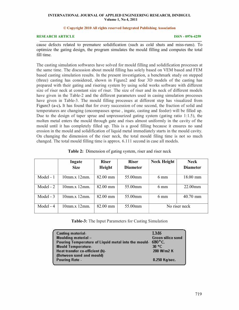
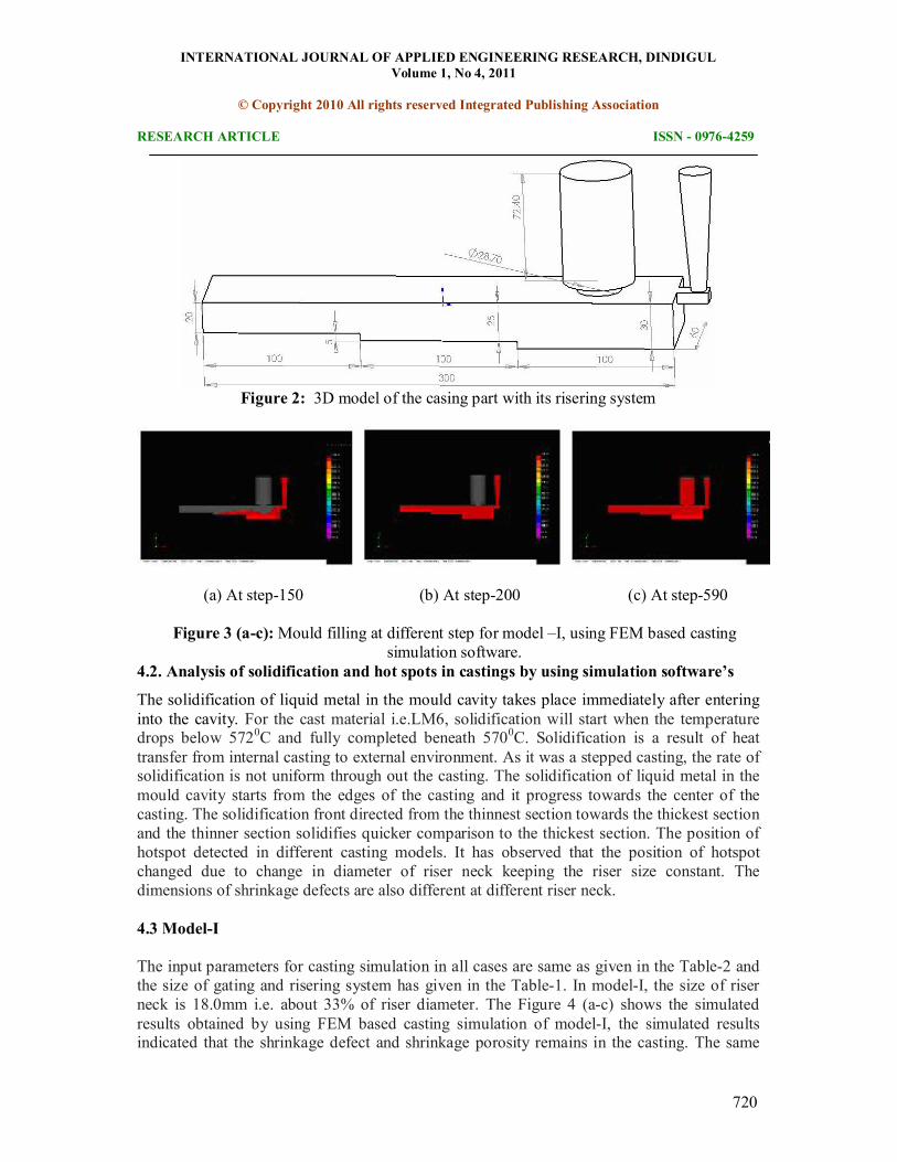
The casting simulation softwares have solved for mould filling and solidification processes at the same time. The discussion about mould filling has solely based on VEM based and FEM based casting simulation results. In the present investigation, a benchmark study on stepped (three) casting has considered, shown in Figure2 and four 3D models of the casting has prepared with their gating and risering system by using solid works software with different size of riser neck at constant size of riser. The size of riser and its neck of different models have given in the Table2 and the different parameters used in casing simulation processes have given in Table3. The mould filling processes at different step has visualized from Figure3 (ac). It has found that for every succession of one second, the fraction of solid and temperatures are changing (encompasses sprue , ingate, casting and feeder) will be filled up. Due to the design of taper sprue and unpressurized gating system (gating ratio 1:1.5), the molten metal enters the mould through gate and rises almost uniformly in the cavity of the mould until it has completely filled up. This is a good filling because it ensures no sand erosion in the mould and solidification of liquid metal immediately starts in the mould cavity. On changing the dimension of the riser neck, the total mould filing time is not so much changed. The total mould filling time is approx. 6.111 second in case all models.
Table 2: Dimension of gating system, riser and riser neck
Ingate Size
Riser Height
Riser Diameter
Neck Height Neck Diameter
Model 1 10mm.x 12mm. 82.00 mm 55.00mm 6 mm 18.00 mm
Model 2 10mm.x 12mm. 82.00 mm 55.00mm 6 mm 22.00mm
Model 3 10mm.x 12mm. 82.00 mm 55.00mm 6 mm 40.70 mm
Model 4 10mm.x 12mm. 82.00 mm 55.00mm No riser neck
Table3: The Input Parameters for Casting Simulation
INTERNATIONAL JOURNAL OF APPLIED ENGINEERING RESEARCH, DINDIGUL Volume 1, No 4, 2011
© Copyright 2010 All rights reserved Integrated Publishing Association
RESEARCH ARTICLE ISSN 09764259
720
Figure 2: 3D model of the casing part with its risering system
(a) At step150 (b) At step200 (c) At step590
Figure 3 (ac):Mould filling at different step for model –I, using FEM based casting simulation software.
4.2. Analysis of solidification and hot spots in castings by using simulation software’s
The solidification of liquid metal in the mould cavity takes place immediately after entering into the cavity. For the cast material i.e.LM6, solidification will start when the temperature drops below 572 0 C and fully completed beneath 570 0 C. Solidification is a result of heat transfer from internal casting to external environment. As it was a stepped casting, the rate of solidification is not uniform through out the casting. The solidification of liquid metal in the mould cavity starts from the edges of the casting and it progress towards the center of the casting. The solidification front directed from the thinnest section towards the thickest section and the thinner section solidifies quicker comparison to the thickest section. The position of hotspot detected in different casting models. It has observed that the position of hotspot changed due to change in diameter of riser neck keeping the riser size constant. The dimensions of shrinkage defects are also different at different riser neck.
4.3 ModelI
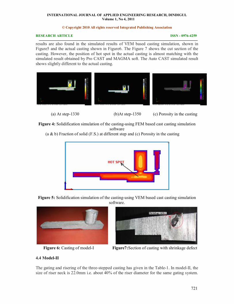
The input parameters for casting simulation in all cases are same as given in the Table2 and the size of gating and risering system has given in the Table1. In modelI, the size of riser neck is 18.0mm i.e. about 33% of riser diameter. The Figure 4 (ac) shows the simulated results obtained by using FEM based casting simulation of modelI, the simulated results indicated that the shrinkage defect and shrinkage porosity remains in the casting. The same
INTERNATIONAL JOURNAL OF APPLIED ENGINEERING RESEARCH, DINDIGUL Volume 1, No 4, 2011
© Copyright 2010 All rights reserved Integrated Publishing Association
RESEARCH ARTICLE ISSN 09764259
721
results are also found in the simulated results of VEM based casting simulation, shown in Figure5 and the actual casting shown in Figure6. The Figure 7 shows the cut section of the casting. However, the position of hot spot in the actual casting is almost matching with the simulated result obtained by Pro CAST and MAGMA soft. The Auto CAST simulated result shows slightly different to the actual casting.
(a) At step1330 (b)At step1350 (c) Porosity in the casting
Figure 4: Solidification simulation of the castingusing FEM based cast casting simulation software
(a & b) Fraction of solid (F.S.) at different step and (c) Porosity in the casting
Figure 5: Solidification simulation of the castingusing VEM based cast casting simulation software.
Figure 6: Casting of modelI Figure7:Section of casting with shrinkage defect
4.4 ModelII
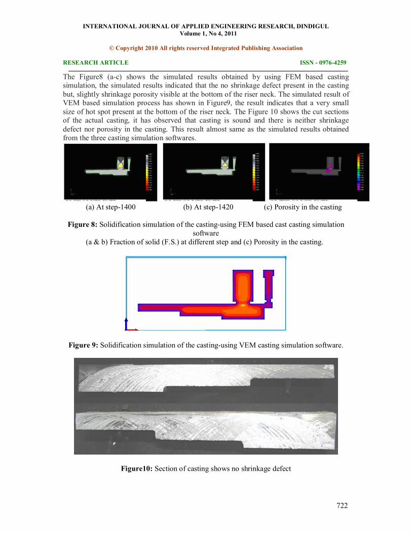
The gating and risering of the threestepped casting has given in the Table1. In modelII, the size of riser neck is 22.0mm i.e. about 40% of the riser diameter for the same gating system.
INTERNATIONAL JOURNAL OF APPLIED ENGINEERING RESEARCH, DINDIGUL Volume 1, No 4, 2011
© Copyright 2010 All rights reserved Integrated Publishing Association
RESEARCH ARTICLE ISSN 09764259
722
The Figure8 (ac) shows the simulated results obtained by using FEM based casting simulation, the simulated results indicated that the no shrinkage defect present in the casting but, slightly shrinkage porosity visible at the bottom of the riser neck. The simulated result of VEM based simulation process has shown in Figure9, the result indicates that a very small size of hot spot present at the bottom of the riser neck. The Figure 10 shows the cut sections of the actual casting, it has observed that casting is sound and there is neither shrinkage defect nor porosity in the casting. This result almost same as the simulated results obtained from the three casting simulation softwares.
(a) At step1400 (b) At step1420 (c) Porosity in the casting
Figure 8: Solidification simulation of the castingusing FEM based cast casting simulation software
(a & b) Fraction of solid (F.S.) at different step and (c) Porosity in the casting.
Figure 9: Solidification simulation of the castingusing VEM casting simulation software.
Figure10: Section of casting shows no shrinkage defect
INTERNATIONAL JOURNAL OF APPLIED ENGINEERING RESEARCH, DINDIGUL Volume 1, No 4, 2011
© Copyright 2010 All rights reserved Integrated Publishing Association
RESEARCH ARTICLE ISSN 09764259
723
4.5 ModelIII
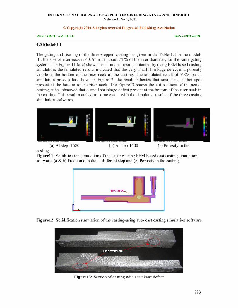
The gating and risering of the threestepped casting has given in the Table1. For the model III, the size of riser neck is 40.7mm i.e. about 74 % of the riser diameter, for the same gating system. The Figure 11 (ac) shows the simulated results obtained by using FEM based casting simulation; the simulated results indicated that the very small shrinkage defect and porosity visible at the bottom of the riser neck of the casting. The simulated result of VEM based simulation process has shows in Figure12; the result indicates that small size of hot spot present at the bottom of the riser neck. The Figure13 shows the cut sections of the actual casting, it has observed that a small shrinkage defect present at the bottom of the riser neck in the casting. This result matched to some extent with the simulated results of the three casting simulation softwares.
(a) At step 1580 (b) At step1600 (c) Porosity in the casting Figure11: Solidification simulation of the castingusing FEM based cast casting simulation software, (a & b) Fraction of solid at different step and (c) Porosity in the casting.
Figure12: Solidification simulation of the castingusing auto cast casting simulation software.
Figure13: Section of casting with shrinkage defect
INTERNATIONAL JOURNAL OF APPLIED ENGINEERING RESEARCH, DINDIGUL Volume 1, No 4, 2011
© Copyright 2010 All rights reserved Integrated Publishing Association
RESEARCH ARTICLE ISSN 09764259
724
4.6 ModelIV
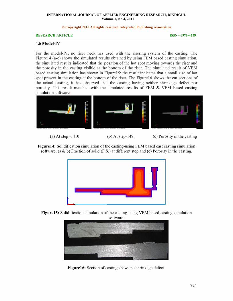
For the modelIV, no riser neck has used with the risering system of the casting. The Figure14 (ac) shows the simulated results obtained by using FEM based casting simulation, the simulated results indicated that the position of the hot spot moving towards the riser and the porosity in the casting visible at the bottom of the riser. The simulated result of VEM based casting simulation has shown in Figure15; the result indicates that a small size of hot spot present in the casting at the bottom of the riser. The Figure16 shows the cut sections of the actual casting, it has observed that the casting having neither shrinkage defect nor porosity. This result matched with the simulated results of FEM & VEM based casting simulation software.
(a) At step 1410 (b) At step149. (c) Porosity in the casting
Figure14: Solidification simulation of the castingusing FEM based cast casting simulation software, (a & b) Fraction of solid (F.S.) at different step and (c) Porosity in the casting.
Figure15: Solidification simulation of the castingusing VEM based casting simulation software.
Figure16: Section of casting shows no shrinkage defect.
INTERNATIONAL JOURNAL OF APPLIED ENGINEERING RESEARCH, DINDIGUL Volume 1, No 4, 2011
© Copyright 2010 All rights reserved Integrated Publishing Association
RESEARCH ARTICLE ISSN 09764259
725
The above simulation and experimental work shows that the riser neck plays a vital role casting process. The use of casting simulation process can able to optimize the design of riser neck in very short time comparable to the conventional methods.
5. Conclusion
The application of computeraided methoding, solid modeling, and casting simulation technologies in foundries can able to minimize the bottlenecks and nonvalue added time in casting development, as it reduces the number of trial casting required on the shop floor. In addition, the optimization of riser neck reduces or completely removes the occurrence of shrinkage defect in the casting. The application of casting simulation software based on finite element method and vector element method, shows good results and matched with the experimental results. The benchmark study reveals that the use of casting simulation softwares reduces the iteration time for modification of methoding and to reach at a safe design of riser neck. It has also proven to be very useful for verifying the manufacturability of a casting and improving it by minor modifications to part geometry, before freezing the design in early stages of product lifecycle. Application of casting simulation softwares in foundries can be able to optimize the size and the position of the riser neck to avoid shrinkage defect in the casting.
Acknowledgement
Authors thankfully acknowledge the financial support provided by U.G.C , New Delhi under Major Research Project Grant [ F.No. – 3288/ 2006 (SR) dated 09.03.2007 ] without which this work could not be attempted.
6. References
1. Application of Commercial Software Package “Procast” to the Prediction of Shrinkage Porosity in Investment Castings. www.mmat.ubc.ca/databases/ Details.asp?id=354, accessed during February, 2011.
2. Viswanathan, W.D.Porter, Using of Simulation in Optimizing Mould Filling, AFS Transactions 98(59), pp.477483.
3. Ravi, B. and Joshi, D., (2007) Feedability Analysis and Optimisation Driven by Casting Simulation, Indian Foundry Journal, 53(6), pp.7178.
4. Prabhakara Rao, P., Chakravarthy, G., S.Kumar, A. C. and Srinivasa Rao, G. (2009), 57th Indian Foundry Congress,Computerized simulation of sand casting process” Institute of India Foundrymen, Kolkata, February.
5. Ravi, B. (2008), Casting method optimization driven by simulation, Minerals & Metals Review –March, 54(1), pp.3943.
6. Ravi, B. (2008), Casting Simulation and Optimisation: Benefits, Bottlenecks, and Best Practices, Indian Foundry Journal, 54 (1), 4752.
INTERNATIONAL JOURNAL OF APPLIED ENGINEERING RESEARCH, DINDIGUL Volume 1, No 4, 2011
© Copyright 2010 All rights reserved Integrated Publishing Association
RESEARCH ARTICLE ISSN 09764259
726
7. Joshi, D . and Ravi, B. (2008),Classification and Simulation based Design of 3D Junctions in Castings, American Foundry Society.
8. Ravi, B. and Srinivasan, M.N. (1990), Hot spots in Castings computer aided Location and Experimental Validation, Transactions of the AFS, 98, pp.353357.
9. Ravi, B. (2005), Metal Casting: ComputerAided Design and Analysis, PrenticeHall India, New Delhi, 1 st edition.