Solid or shell finite elements to model thick cylindrical...
40
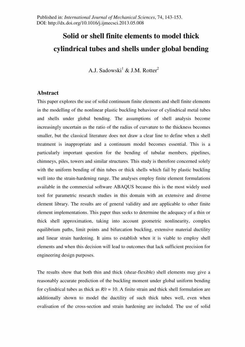
Published in: International Journal of Mechanical Sciences, 74, 143-153. DOI: http://dx.doi.org/10.1016/j.ijmecsci.2013.05.008 Solid or shell finite elements to model thick cylindrical tubes and shells under global bending A.J. Sadowski 1 & J.M. Rotter 2 Abstract This paper explores the use of solid continuum finite elements and shell finite elements in the modelling of the nonlinear plastic buckling behaviour of cylindrical metal tubes and shells under global bending. The assumptions of shell analysis become increasingly uncertain as the ratio of the radius of curvature to the thickness becomes smaller, but the classical literature does not draw a clear line to define when a shell treatment is inappropriate and a continuum model becomes essential. This is a particularly important question for the bending of tubular members, pipelines, chimneys, piles, towers and similar structures. This study is therefore concerned solely with the uniform bending of thin tubes or thick shells which fail by plastic buckling well into the strain-hardening range. The analyses employ finite element formulations available in the commercial software ABAQUS because this is the most widely used tool for parametric research studies in this domain with an extensive and diverse element library. The results are of general validity and are applicable to other finite element implementations. This paper thus seeks to determine the adequacy of a thin or thick shell approximation, taking into account geometric nonlinearity, complex equilibrium paths, limit points and bifurcation buckling, extensive material ductility and linear strain hardening. It aims to establish when it is viable to employ shell elements and when this decision will lead to outcomes that lack sufficient precision for engineering design purposes. The results show that both thin and thick (shear-flexible) shell elements may give a reasonably accurate prediction of the buckling moment under global uniform bending for cylindrical tubes as thick as R/t = 10. A finite strain and thick shell formulation are additionally shown to model the ductility of such thick tubes well, even when ovalisation of the cross-section and strain hardening are included. The use of solid
Transcript of Solid or shell finite elements to model thick cylindrical...
Published in: International Journal of Mechanical Sciences, 74, 143-153. DOI: http://dx.doi.org/10.1016/j.ijmecsci.2013.05.008
Solid or shell finite elements to model thick
cylindrical tubes and shells under global bending
A.J. Sadowski1 & J.M. Rotter2
Abstract
This paper explores the use of solid continuum finite elements and shell finite elements
in the modelling of the nonlinear plastic buckling behaviour of cylindrical metal tubes
and shells under global bending. The assumptions of shell analysis become
increasingly uncertain as the ratio of the radius of curvature to the thickness becomes
smaller, but the classical literature does not draw a clear line to define when a shell
treatment is inappropriate and a continuum model becomes essential. This is a
particularly important question for the bending of tubular members, pipelines,
chimneys, piles, towers and similar structures. This study is therefore concerned solely
with the uniform bending of thin tubes or thick shells which fail by plastic buckling
well into the strain-hardening range. The analyses employ finite element formulations
available in the commercial software ABAQUS because this is the most widely used
tool for parametric research studies in this domain with an extensive and diverse
element library. The results are of general validity and are applicable to other finite
element implementations. This paper thus seeks to determine the adequacy of a thin or
thick shell approximation, taking into account geometric nonlinearity, complex
equilibrium paths, limit points and bifurcation buckling, extensive material ductility
and linear strain hardening. It aims to establish when it is viable to employ shell
elements and when this decision will lead to outcomes that lack sufficient precision for
engineering design purposes.
The results show that both thin and thick (shear-flexible) shell elements may give a
reasonably accurate prediction of the buckling moment under global uniform bending
for cylindrical tubes as thick as R/t = 10. A finite strain and thick shell formulation are
additionally shown to model the ductility of such thick tubes well, even when
ovalisation of the cross-section and strain hardening are included. The use of solid

Published in: International Journal of Mechanical Sciences, 74, 143-153. DOI: http://dx.doi.org/10.1016/j.ijmecsci.2013.05.008
continuum elements to model tubes in bending is found to become increasingly
uneconomical as the R/t ratio rises above 25 with reduced advantages over shell
elements, both in terms of the accuracy of the solution and the computation time.
Keywords
Shell finite elements, continuum solid finite elements, plasticity, strain hardening, thick
cylindrical shells, bending.
1 Lecturer, Imperial College London, UK
2 Professor of Civil Engineering, The University of Edinburgh, UK
Published in: International Journal of Mechanical Sciences, 74, 143-153. DOI: http://dx.doi.org/10.1016/j.ijmecsci.2013.05.008
1. Introduction
Thin-walled shell theory is characterised by fundamental assumptions which allow
shell structures to be analysed in an efficient manner by effectively reducing the
dimensions of the problem from three to two. Bushnell [1] summarises the familiar
assumptions behind 'thin' or 'first-order' plate/shell theory, also known as Kirchhoff-
Love theory [2-5], as follows:
I. Normals to the shell reference surface remain straight after deformation.
II. Normals to the shell reference surface remain normal after deformation.
III. The transverse normal stress is negligible.
Further, though sometimes not specifically stated, this formulation also assumed that
the strains are small compared with unity [6,7] and that the shell thickness is
unchangeable (i.e. that the Poisson out-of-plane thickness changes can be ignored). A
'thick' or 'second-order' plate/shell theory is obtained by discarding Assumption II
above, taking transverse shear deformation into account, and is known as Mindlin-
Reissner theory [8,9]. Progressively higher-order theories are obtained by additionally
discarding first Assumption I and then III, leading to a full three-dimensional
continuum theory with explicit modelling of all stress and strain components and
changes of thickness (e.g. [10-13]).
A decision on the choice between a thin or thick shell approximation or a full three-
dimensional analysis is not straightforward, since it depends strongly on the context.
Flügge [14] suggested that “the shell thickness t should be small” compared to its other
dimensions. Timoshenko and Woinowsky-Krieger [15] wrote that thin shell theory is
not rigorous enough when the thickness of a shell is “comparable to its radius of
curvature R” and that thick shell theory, or a full three-dimensional analysis, should be
applied instead. Heyman [77] suggested that the term 'thin shell' refers to those with
R/t > 20. Brush and Almroth [6] wrote simply that R/t >> 1 for thin shell theory to
apply. Bushnell [16] made a similar recommendation while Calladine [5] put a value
on this limit, suggesting that shells as thick as R/t = 10 may be suitable for a “thin
shell” treatment. The theory manual of the widely used ABAQUS [17] finite element
software recommends the application of transverse shear-flexible 'thick' shell elements
when the thickness is “more than about 1/15 of a characteristic length on the surface of
the shell”, which has multiple possible interpretations (e.g. R or Rt or 2.4 Rt ) and
Published in: International Journal of Mechanical Sciences, 74, 143-153. DOI: http://dx.doi.org/10.1016/j.ijmecsci.2013.05.008
so is slightly unclear. Many other classical guidelines exist and each is similarly
vague.
The above ideas are all loosely based on order-of-magnitude assessments of analytical
solutions to relatively simple linear-elastic problems and it is clear that all attempt to
give advice, rather than a firm rule. The present paper seeks to establish the validity of
a shell theory approximation for the specific and practically important problem of thick
cylindrical shells or thin tubular members (radius to thickness ratio R/t ≤ 50) of
medium length (length to radius ratio L/R = 7) subject to global bending. This
configuration is significantly more complex than the elastic cases often considered in
classical texts, and includes geometric nonlinearity with local bending effects,
extensive material plasticity, strain hardening, and both limit point and bifurcation
buckling. This problem is an important and well-understood classical benchmark
against which different theoretical analyses and modelling techniques may be tested.
Since cylinders even thicker than those of this study are used as tubular structural
members, those studied here are termed “thin tubes”. By contrast, most of the
literature on cylindrical shells is concerned with much thinner structures than are
studied here, so the same cylinders are here termed “thick shells”. These two terms are
used here to refer to the same structure. This paper forms part of a study that seeks to
resolve the mismatches that currently exist between these two descriptions of the same
item.
2. Behaviour of thick shells under global bending
When a bending moment is applied to the ends of a cylindrical tube or shell, the end
cross-section rotates in the sense of the moment, inducing axial membrane
compression on one side of the tube and corresponding tension on the opposite side.
The system has two stable equilibrium paths, shown in Fig. 1 in terms of the applied
end moment M (normalised by the full plastic moment Mp) against the end rotation θ.
The primary path is elastic and close to linear until a moment approaching
approximately 0.83Mp (the first yield moment My), after which inelastic strains develop
and the tangent stiffness decreases significantly. In the thicker tubes (approximately
R/t < 50), the response remains almost geometrically linear up to Mp. If a

Published in: International Journal of Mechanical Sciences, 74, 143-153. DOI: http://dx.doi.org/10.1016/j.ijmecsci.2013.05.008
geometrically linear elastic-plastic numerical analysis (termed MNA) is used to
continue on this path, the analysis predicts indefinite strain hardening, but naturally
there can be no loss of stability. A geometrically nonlinear elastic-plastic numerical
analysis (termed GMNA) predicts that significant ovalisation occurs after Mp has been
exceeded, producing two causes for the loss of tangent stiffness until a limit point is
reached [18-22]. This limit point corresponds to a snap-through buckle, and may be
followed by a bifurcation in the post-buckling regime (Fig. 1). The possibility of
ovalisation causing elastic snap-through buckling, known as the Brazier effect
[5,23,24], is only appropriate to very long cylinders, and thick tubes fail by plastic
collapse before they reach the critical Brazier moment. The plastic collapse of very
thick cylinders involves extensive material straining, and this poses a significant
challenge for many finite element models.
Fig. 1 – Qualitative illustration of the equilibrium paths in cylinders with L/R = 7 and a
strain hardening material law (cylinders of different length exhibit similar qualitative
features)
Following a possible bifurcation, a secondary path may produce localised axial
wrinkles on the compressed side. The point of bifurcation is strongly dependent on the
R/t ratio. If the tube is very thick, the response follows the primary ovalisation path

Published in: International Journal of Mechanical Sciences, 74, 143-153. DOI: http://dx.doi.org/10.1016/j.ijmecsci.2013.05.008
past the limit point to large deformations without bifurcating [25-27]. In slightly
thinner cylinders, bifurcation may occur after the limit point, but for cylinders thinner
than R/t = 50, bifurcation onto the secondary path occurs before the limit point is
reached and the tube exhibits elastic-plastic bifurcation. Perfect cylinders with R/t >
200 suffer elastic bifurcation buckling [18,28,29,30,31,32]. The issue of wrinkling
following bifurcation is important for a finite element model because it involves high
local shell curvatures, so the elements must be able to accommodate these.
3. Finite element modelling of thick shells under global bending
A large body of research exists on the computational modelling of cylindrical tubes in
bending, as it has wide applications in many engineering situations. Early work on
numerical solutions to the nonlinear ovalisation aspect of tubes in bending may be
traced back to Ades [33], Reissner [34], Axelrad [35], Kempner and Chen [36],
Kedward [37] and others, but finite element formulations arguably appeared some time
later. For example, Row et al. [26] presented a two-dimensional finite element for the
analysis of thick-walled cylinders in the context of deep-water pipelines. Karamanos
and Tassoulas [27] employed specialised nonlinear 'tube elements' based on a finite
strain formulation by Needleman [38] enhanced with the J2-flow theory of plasticity
(von Mises yield criterion [39]) to study the elastic-plastic behaviour of tubes under
both external pressure and bending, with the results being in very good agreement with
experimental data [40]. Kyriakides and Ju [30,41] analysed the inelastic response of
aluminium tubes in bending using experiments and numerical studies assuming their
own small-strain J2-flow plasticity theory shell finite element formulation and exact
modelling of circular geometries, with excellent agreement between the two.
Karamanos and Tassoulas [42,43] compared numerical predictions of local elastic-
plastic buckling for thick tubes with R/t = 21 and L/R = 20 under bending using similar
'tube elements' with experimental data, also successfully. More recently, Karamanos
and Houliara [31,44,45] studied the elastic bifurcation buckling behaviour of long thin-
walled tubes under bending (R/t > 100 and 'infinite' L/R) using a similar 'tube element'
formulation. Though successful, the numerical formulations presented in these
publications are highly specialised and effectively beyond the reach of practising
engineers and most researchers, who generally rely on commercially available finite
element software.
Published in: International Journal of Mechanical Sciences, 74, 143-153. DOI: http://dx.doi.org/10.1016/j.ijmecsci.2013.05.008
In recent years, several studies emerged on the elastic-plastic behaviour of tubes under
combined bending and internal pressure in relation to buried pipelines. These involved
experiments but extended the knowledge base with extensive finite element analyses
using ABAQUS. They key effect of internal pressure is that it stabilises the tube and
usually pushes bifurcation buckling into the plastic material range. In particular,
Jayadevan et al. [46] and Østby et al. [47] studied the large plastic deformation
behaviour of very thick tubes with R/t = 10 under tension and bending respectively in
the context of the fracture response of pipelines using the reduced-integration second
order ABAQUS C3D20R solid continuum element and an isotropic power-law strain
hardening material model. Further, Corona et al. [48] applied the fully-integrated
second order ABAQUS C3D27 solid continuum element to model thick tubes with R/t
≈ 18 under bending using an elastic-plastic Ramberg-Osgood [49] strain hardening
material model. Limam et al. [50] used the fully-integrated first order ABAQUS S4
thick shell element with a similar strain hardening model based on a Ramberg-Osgood
empirical fit to measured material properties. They successfully reproduced
experimental moment-curvature curves for pressurised shells as thick as R/t ≈ 26 with
L/R ranging from 22 to 34. Lastly, Limam et al. [51] modelled similarly thick shells
with L/R = 10 using instead the fully-integrated first order ABAQUS C3D8 solid
continuum element and obtained the same degree of success in reproducing
experimental results.
The abovementioned studies suggest that an accurate modelling of the plastic material
response is crucial for thick cylinders under global bending. Together, these authors
showed conclusively that both the shell and solid theoretical treatments may be used
successfully to model the buckling of tubes with realistic, large strain, inelastic
material behaviour. Although these studies partially addressed the same topic as is
covered by the work presented here, they gave little justification for their choice of
theory and did not investigate whether a solid or shell element was necessary in each
case. The apparent bias towards ABAQUS is purely coincidental, and the authors are
not aware of any published computational studies of tubes in bending which use other
commercial finite element software.

Published in: International Journal of Mechanical Sciences, 74, 143-153. DOI: http://dx.doi.org/10.1016/j.ijmecsci.2013.05.008
The present paper is an attempt to provide rigorous numerical evidence to aid in the
selection of an appropriate finite element by comparing the predicted nonlinear plastic
buckling behaviours of thick and thin tubes under global bending when modelled using
several solid continuum finite elements and several shell elements. Three different
radius to thickness (R/t) ratios were chosen: 10, 25 and 50. The ratio R/t = 10 is a tube
so thick that shell theory may be thought quite inappropriate (see initial discussion),
while R/t = 50 should be well within the range where a thin shell treatment has
traditionally been thought to be acceptable. The cylinder was assumed to be of
medium length with L/R = 7, of sufficient length for the local shell bending effects near
the end boundaries to have little influence on the result [22,32,46,47].
4. Numerical treatment used in this study
Three cylindrical tubes with radius to thickness (R/t) ratios of 10, 25 and 50 were
modelled using finite elements corresponding to thick and thin shell and solid
continuum theoretical treatments. All analyses were undertaken using geometrically
and materially nonlinear analysis (GMNA), as defined in the European Standard on
shell buckling EN 1993-1-6 [52], to fully capture distortions, ovalisation and
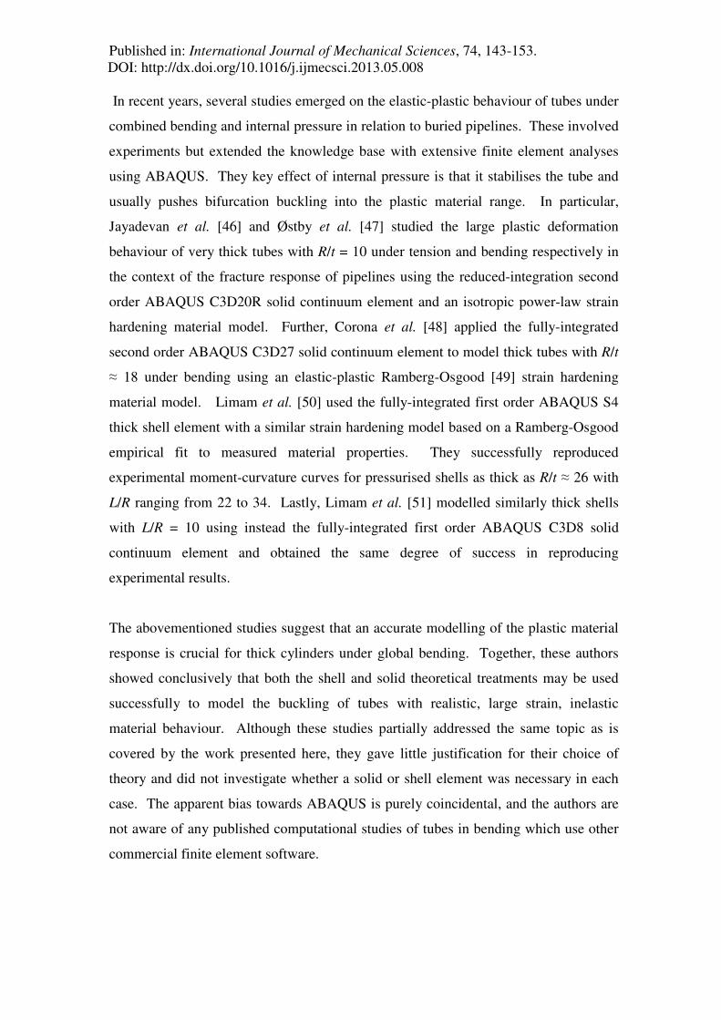
bifurcations. To provide relatively generic conclusions, the material properties were
taken as a characterised version of the uniaxial tensile behaviour of a mild isotropic
steel (Fig. 2), with elastic modulus E = 200 GPa, linear-elastic up to a first yield stress
of σy = 250 MPa, followed by 2.5% linear strain hardening up to an ultimate stress of
σu = 380 MPa. For simplicity, after the ultimate stress σu was reached, an indefinitely
ductile plateau was assumed and no rupture or cracking was implemented in the
material model. ABAQUS [17] v.6.10.1 was used and the nonlinear equilibrium path
was followed using the Riks modified arc-length method [53]. This particular choice of
software package was made due to its widespread use and credibility in previous
research work in this field and due to its arguably very extensive element library,
though the results may readily be generalised to other commercial and academic finite
element packages.
Published in: International Journal of Mechanical Sciences, 74, 143-153. DOI: http://dx.doi.org/10.1016/j.ijmecsci.2013.05.008
0 0.13 2.73 % strain
380 250
Stress (MPa)
E
0.025E
σu
σy
Fig. 2 – Assumed engineering stress-strain relation, with 2.5% linear strain hardening
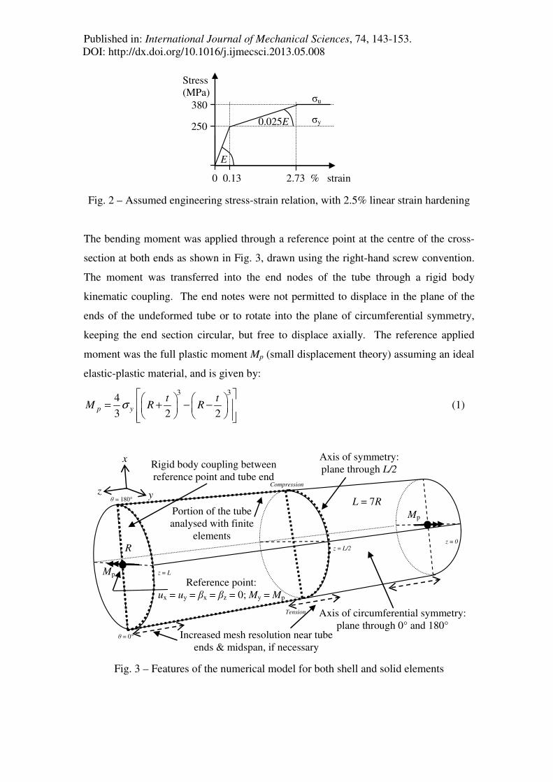
The bending moment was applied through a reference point at the centre of the cross-
section at both ends as shown in Fig. 3, drawn using the right-hand screw convention.
The moment was transferred into the end nodes of the tube through a rigid body
kinematic coupling. The end notes were not permitted to displace in the plane of the
ends of the undeformed tube or to rotate into the plane of circumferential symmetry,
keeping the end section circular, but free to displace axially. The reference applied
moment was the full plastic moment Mp (small displacement theory) assuming an ideal
elastic-plastic material, and is given by:
3 34
3 2 2p y
t tM R Rσ
= + − −
(1)
Axis of symmetry: plane through L/2
Portion of the tube analysed with finite
elements
Axis of circumferential symmetry: plane through 0° and 180°
Reference point: ux = uy = βx = βz = 0; My = Mp
y
x
z
Rigid body coupling between reference point and tube end
θ = 0°
θ = 180°
z = 0 z = L/2
z = L Mp
R
L = 7R
Increased mesh resolution near tube ends & midspan, if necessary
Mp
Compression
Tension
Fig. 3 – Features of the numerical model for both shell and solid elements
Published in: International Journal of Mechanical Sciences, 74, 143-153. DOI: http://dx.doi.org/10.1016/j.ijmecsci.2013.05.008
The tube geometry was initially assumed to be perfect with no modelled imperfections.
Symmetry conditions were exploited where possible for a more efficient analysis (Fig.
3), consistent with previous numerical research [46,47,50,51]. Because the
calculations were performed on a powerful computer, it was not considered necessary
to economise on the mesh and some analyses employed many more dofs than was
strictly necessary. Local shell bending effects were observed near the ends (z = 0, L) in
tubes with R/t = 25 and 50 as well as local bifurcation buckling at midspan (z = L/2), so
the mesh resolution was increased at these locations to keep the element size well
below 0.25 Rt (i.e. approximately 10% of the linear axial bending half-wavelength λ
≈ 2.44 Rt or 14% of the classical axisymmetric buckle wavelength λcl ≈ 1.73 Rt
[54,55]). This mesh resolution was verified by a careful initial mesh convergence
study.
The extensive ABAQUS [17] element library contains many elements corresponding
closely to generic solid continuum and thick and thin shell finite element formulations.
It is unfeasible and unnecessary to test all possible elements for this specific problem,
so a representative selection was made of three element types from each of the
theoretical treatments. Tetrahedral and triangular elements are known to be sometimes
unreliable and overly stiff [17,56,57] for problems involving extensive bending or high
strain gradients, unless used with an extremely fine mesh, so only hexahedral and
rectangular elements were used. The chosen solid and shell elements are summarised
in Tables 1 and 2 respectively.
Published in: International Journal of Mechanical Sciences, 74, 143-153. DOI: http://dx.doi.org/10.1016/j.ijmecsci.2013.05.008
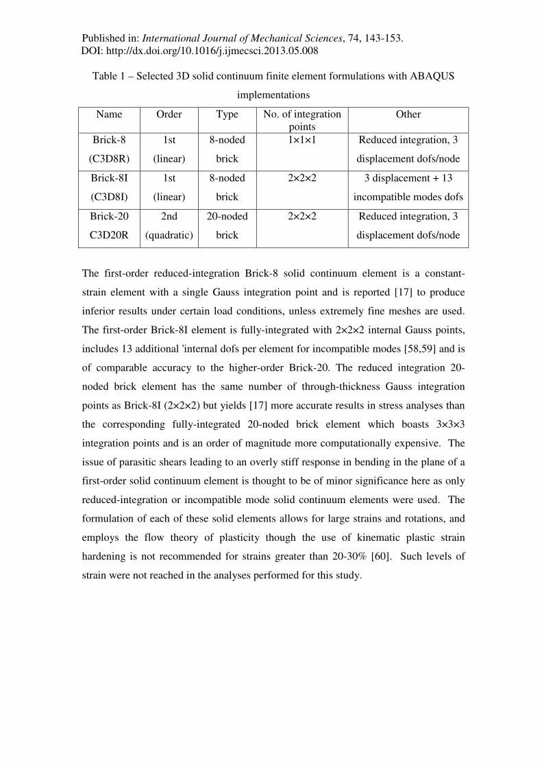
Table 1 – Selected 3D solid continuum finite element formulations with ABAQUS
implementations
Name Order Type No. of integration points
Other
Brick-8
(C3D8R)
1st
(linear)
8-noded
brick
1×1×1 Reduced integration, 3
displacement dofs/node
Brick-8I
(C3D8I)
1st
(linear)
8-noded
brick
2×2×2 3 displacement + 13
incompatible modes dofs
Brick-20
C3D20R
2nd
(quadratic)
20-noded
brick
2×2×2 Reduced integration, 3
displacement dofs/node
The first-order reduced-integration Brick-8 solid continuum element is a constant-
strain element with a single Gauss integration point and is reported [17] to produce
inferior results under certain load conditions, unless extremely fine meshes are used.
The first-order Brick-8I element is fully-integrated with 2×2×2 internal Gauss points,
includes 13 additional 'internal dofs per element for incompatible modes [58,59] and is
of comparable accuracy to the higher-order Brick-20. The reduced integration 20-
noded brick element has the same number of through-thickness Gauss integration
points as Brick-8I (2×2×2) but yields [17] more accurate results in stress analyses than
the corresponding fully-integrated 20-noded brick element which boasts 3×3×3
integration points and is an order of magnitude more computationally expensive. The
issue of parasitic shears leading to an overly stiff response in bending in the plane of a
first-order solid continuum element is thought to be of minor significance here as only
reduced-integration or incompatible mode solid continuum elements were used. The
formulation of each of these solid elements allows for large strains and rotations, and
employs the flow theory of plasticity though the use of kinematic plastic strain
hardening is not recommended for strains greater than 20-30% [60]. Such levels of
strain were not reached in the analyses performed for this study.

Published in: International Journal of Mechanical Sciences, 74, 143-153. DOI: http://dx.doi.org/10.1016/j.ijmecsci.2013.05.008
Table 2 – Selected 3D structural shell finite element formulations with ABAQUS
implementation
Name Order Type Shell theory Other
Thick-
shell-4
(S4R)
1st
(linear)
4-noded
doubly-curved
rectangle
Thick & thin
depending
on thickness
Finite strain, reduced integration,
hourglass control, 6 dofs/node
Thick-
shell-8
(S8R)
2nd
(quadratic)
8-noded
doubly-curved
rectangle
Thick Small strain, finite rotation,
reduced integration, 6 dofs/node
Thin-
shell-9
(S9R5)
2nd
(quadratic)
9-noded
doubly-curved
rectangle
Thin Small strain, finite rotation,
reduced integration, 5 dofs/node
Each of the shell elements investigated in this study employs reduced integration,
which permits extensive savings in computation time. Additionally, such elements are
known to be generally free of shear locking [17,61,62,63]. The first-order Thick-shell-
4 element is as a general-purpose shell element with 6 dofs per node (3 displacements
and 3 rotations), applicable for most thick and thin shell applications and permitting
large strains. Its present formulation includes a stabilisation parameter that effectively
eliminates artificial 'hourglass' deformation modes. It employs thick (Mindlin) shell
theory when necessary and becomes a 'discrete Kirchhoff' element for thin shells. The
second-order Thick-shell-8 element is similar and includes finite rotations, though its
formulation only permits small strains is suitable only for thick shell analyses. The
second-order Thin-shell-9 element formulation assumes only 5 dofs per node (3
displacements and 2 tangential rotations) and includes an additional centre node,
apparently for improved numerical stability [17,64,65]. It is recommended for use in
elastic thin-shell buckling problems and it has been described as a robust and efficient
element in a variety of structural engineering problems (e.g. [63,66,67,68]). Lastly,
though all solid elements are naturally capable of modelling changes in wall thickness
due to Poisson effects, the only shell element that can do so is the Thick-shell-4
element due to its finite strain formulation. The strain measures in each of these shell
elements are approximations to those of the Koiter-Sanders shell theory [69]. Other

Published in: International Journal of Mechanical Sciences, 74, 143-153. DOI: http://dx.doi.org/10.1016/j.ijmecsci.2013.05.008
finite strain formulations for shear-flexible shell finite elements include those of Bathe
et al. [70], Ramm et al. [71], Bischoff and Ramm [72] and many others.
The analysis of thick shells or thin tubes subject to global bending is a relatively
'smooth' nonlinear problem with no contact conditions, sharp stress localisations or
severe element distortions [1,17]. A second-order Brick-20 element might therefore be
thought to offer the 'best' solution of all the elements explored. It remains, however,
difficult to say with full certainty a priori which element should give the 'right' answer
for any particular R/t ratio, even for this apparently simple benchmark test. It may also
be noted that experiments on cylinders of this kind tend to display some scatter
between individual apparently identical tests, and the mismatches with computational
predictions are generally comparable in magnitude to the differences between the
predictions of different elements in this study. Consequently no attempt is made here
to select the “correct” result on the basis of a match with physical testing.
5. Results of the nonlinear buckling analyses
5.1 Bending of cylindrical tubes with R/t = 10
The preceding selection of shell and solid continuum elements were used to predict the
behaviour of the thick cylindrical tube with R/t = 10. The peak moments predicted by
each formulation and selected properties of the meshes are summarised in Table 3.
The predicted relationships between applied moment and the normalised mean tube
curvature are presented in Fig. 4, with a close-up view near the limit point in Fig. 5.
This normalised curvature Φ is defined as the ratio of the end rotation βy about the y-
axis (Fig. 3) to its first yield value given by Lσy/(ER) for a cross-section that is free of
ovalisation. A normalised curvature value of unity is thus reached at the point of first
yield in a section that does not distort.

Published in: International Journal of Mechanical Sciences, 74, 143-153. DOI: http://dx.doi.org/10.1016/j.ijmecsci.2013.05.008
Fig. 4 – Normalised moment-curvature curves for R/t = 10
Fig. 5 – Normalised moment-curvature curves for R/t = 10: close-up near limit point
The analyses that employed a solid continuum treatment were all successful in
following the primary load path well into the post-buckling range and predicted a limit
moment at approximately 1.41Mp. This thick cylinder reaches a limit point snap-

Published in: International Journal of Mechanical Sciences, 74, 143-153. DOI: http://dx.doi.org/10.1016/j.ijmecsci.2013.05.008
through buckle (Fig. 6) due to extensive plasticity and cross-section ovalisation. The
possible secondary path, involving axial wrinkling, is not found even very far into the
post-buckling range. The Brick-8I and Brick-20 solid continuum elements predict
nearly identical responses (Fig. 4 & 5), which are slightly stiffer and consequently
stronger (by 0.3%) than the predictions of the Brick-8 and Thick-shell-4 elements. The
very small differences between these three analyses are so tiny as to make them
effectively all the same in engineering terms, so the results from these three elements
are here deemed to be the 'correct' numerical prediction.
The corresponding analyses employing a shell treatment were problematic. The Riks
algorithm was able to follow the primary equilibrium path until the limit point was
almost reached, but encountered severe numerical difficulties when attempting to go
into the post-buckling range. A solution was finally obtained by increasing the number
of section integration points from 5 (default) to at least 5 times that number (Simpson's
rule) together with a small mesh perturbation. This perturbation was axially sinusoidal
but in the ovalising circumferential harmonic two (δ = δosin(πz/L)cos(2θ)) with an
amplitude δo ≈ 10-2t, where θ is the circumferential coordinate (Fig. 3). This form
maintained the ends circular and reflected the shape of the global nonlinear collapse
mode (Fig. 6).
Using this slightly perturbed mesh, the Thick-shell-4 element reproduced the same
path as the Brick-8 element, with an identical limit moment and post-buckling
response, but using far fewer dofs. This success is attributable to its finite strain
formulation, which allows the Thick-shell-4 element to model changes in wall
thickness, albeit not quite as well as the solid continuum elements (Table 3). The
Thick-shell-8 and Thin-shell-9 elements both predicted a limit moment within 2% of
the 'correct' value. However, the predicted post-buckling response was not good, as the
moment dropped to 95% of the limit value at a rotation only slightly greater than half
the correct value. This appears to be caused by the small strain formulation which
renders these elements unable to model changes in wall thickness.

Published in: International Journal of Mechanical Sciences, 74, 143-153. DOI: http://dx.doi.org/10.1016/j.ijmecsci.2013.05.008
Fig. 6 – Predicted buckling modes for R/t = 10
Table 3 – Buckling moments and selected mesh properties for R/t = 10
R/t = 10 Brick-8 Brick-8I Brick-20 Thick-shell-4
Thick-shell-8
Thin-shell-9
No. of elements
through wall thickness
4 4 2 n/a n/a n/a
Axial element size 0.08√(Rt) 0.08√(Rt) 0.17√(Rt) 0.04√(Rt) 0.09√(Rt) 0.08√(Rt)
Total no. of dofs 245,031 1,074,951 137,184 40,632 175,212 232,812
% change in thickness†
(compressive side)
+2.45 +2.46 +2.47 +1.10 n/a n/a
% change in thickness†
(tensile side)
–1.65 –1.68 –1.68 –0.75 n/a n/a
Buckling moment
MGMNA/Mpl
1.411 1.414 1.415 1.411 1.393 1.386
† at the buckling moment

Published in: International Journal of Mechanical Sciences, 74, 143-153. DOI: http://dx.doi.org/10.1016/j.ijmecsci.2013.05.008
Plasticity clearly dominates the failure mode of such thick cylinders under bending.
For an ideal elastic-plastic material without cross-section distortion, the entire cross-
section must be fully yielded to attain the full plastic moment Mp. But in the presence
of strain hardening, Mp is reached and significantly exceeded before bifurcation or a
limit point. It should be recalled that some manner of hardening, be it geometric or
strain-related, is essential for the full plastic moment to be reached in a numerical
analysis, and since cylinders under global bending do not exhibit any geometric
hardening (ovalisation is destabilising), even at massive rotations of the tube ends, Mp
cannot be reached without strain hardening (e.g. [73,74]).
The degree of ovalisation is illustrated in Fig. 7 in terms of the convenient out-of-
roundness parameter U used in the European Standard on shell buckling EN 1993-1-6
[52], defined as U = (Dmax – Dmin)/Dnom where Dnom, Dmin and Dmax are the nominal,
minimum and maximum diameters respectively at any step in the analysis. To provide
a comparison, typical ovalisation fabrication tolerances are of the order of U ≈ 0.01,
whereas for R/t = 10 this study found an ovalisation of U ≈ 0.08 at the maximum
moment. Ovalisation of the cross-section is thus significant in medium-length tubes
even when they are very thick, though the peak moment is of course far below the
elastic Brazier snap-through moment MBraz ≈ 1.035Et2R because of the dominant effect
of plasticity (MBraz/Mp ≈ 20.7, 8.3 and 4.1 for R/t = 10, 25 and 50 respectively).
GMNA
p
M
M
EN 1993-1-6 (2007) 'out-of-roundness' parameter U
1.41
1
0
max min
nom
D DU
D
−=
Limit point > Mp due to strain hardening. Snap-
through buckling.
Very little ovalisation in the initial linear-elastic range:
U ≈ 0.0015 when Mp is reached for R/t = 10.
Extensive ovalisation in the nonlinear range. U ≈ 0.08 at the limit point for R/t = 10.
L/R = 7
Centroidal displacement
Local wall flattening
Compression
Tension
Mp Dnom (nominal diameter)
Dmax > Dnom (normal to plane of bending)
Dmin < Dnom
(in the plane of bending)
0 0.0015 0.08
Fig. 7 – Illustration of the effect of ovalisation for R/t = 10
Published in: International Journal of Mechanical Sciences, 74, 143-153. DOI: http://dx.doi.org/10.1016/j.ijmecsci.2013.05.008
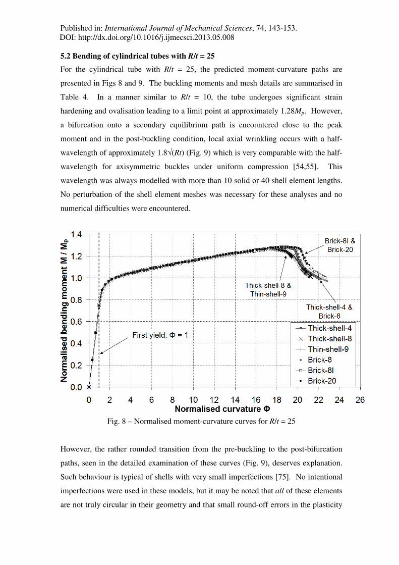
5.2 Bending of cylindrical tubes with R/t = 25
For the cylindrical tube with R/t = 25, the predicted moment-curvature paths are
presented in Figs 8 and 9. The buckling moments and mesh details are summarised in
Table 4. In a manner similar to R/t = 10, the tube undergoes significant strain
hardening and ovalisation leading to a limit point at approximately 1.28Mp. However,
a bifurcation onto a secondary equilibrium path is encountered close to the peak
moment and in the post-buckling condition, local axial wrinkling occurs with a half-
wavelength of approximately 1.8√(Rt) (Fig. 9) which is very comparable with the half-
wavelength for axisymmetric buckles under uniform compression [54,55]. This
wavelength was always modelled with more than 10 solid or 40 shell element lengths.
No perturbation of the shell element meshes was necessary for these analyses and no
numerical difficulties were encountered.
Fig. 8 – Normalised moment-curvature curves for R/t = 25
However, the rather rounded transition from the pre-buckling to the post-bifurcation
paths, seen in the detailed examination of these curves (Fig. 9), deserves explanation.
Such behaviour is typical of shells with very small imperfections [75]. No intentional
imperfections were used in these models, but it may be noted that all of these elements
are not truly circular in their geometry and that small round-off errors in the plasticity
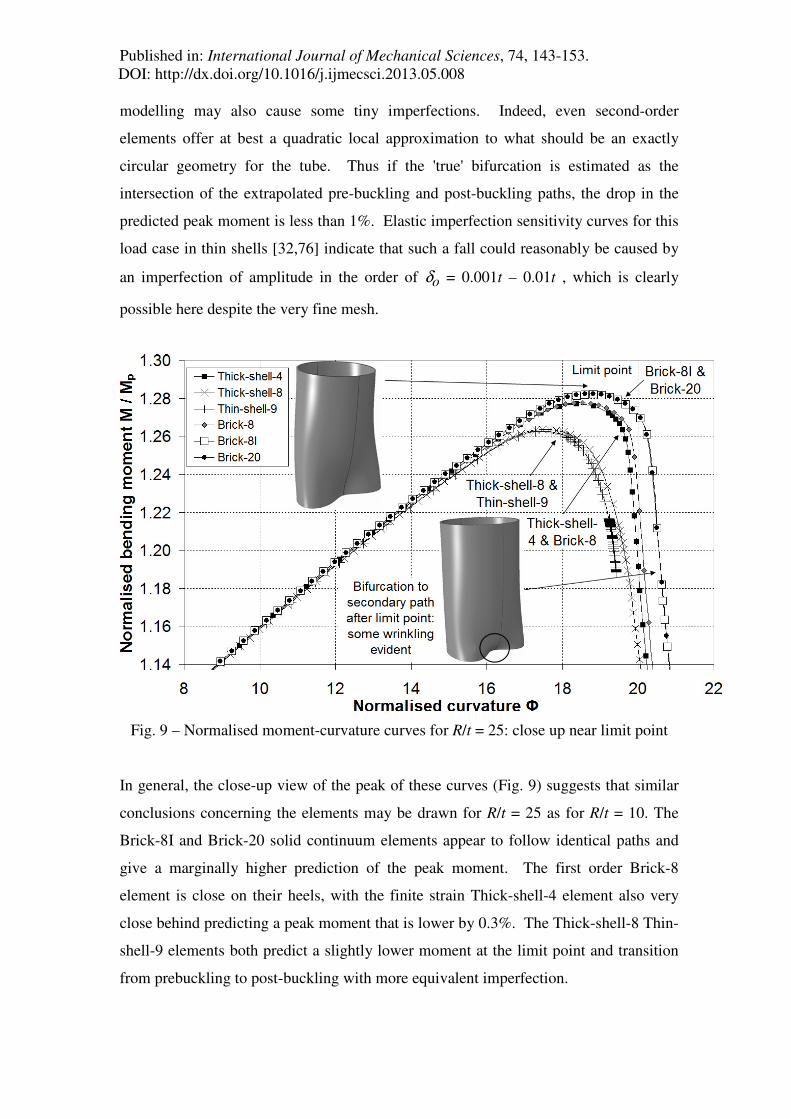
Published in: International Journal of Mechanical Sciences, 74, 143-153. DOI: http://dx.doi.org/10.1016/j.ijmecsci.2013.05.008
modelling may also cause some tiny imperfections. Indeed, even second-order
elements offer at best a quadratic local approximation to what should be an exactly
circular geometry for the tube. Thus if the 'true' bifurcation is estimated as the
intersection of the extrapolated pre-buckling and post-buckling paths, the drop in the
predicted peak moment is less than 1%. Elastic imperfection sensitivity curves for this
load case in thin shells [32,76] indicate that such a fall could reasonably be caused by
an imperfection of amplitude in the order of δo = 0.001t – 0.01t , which is clearly
possible here despite the very fine mesh.
Fig. 9 – Normalised moment-curvature curves for R/t = 25: close up near limit point
In general, the close-up view of the peak of these curves (Fig. 9) suggests that similar
conclusions concerning the elements may be drawn for R/t = 25 as for R/t = 10. The
Brick-8I and Brick-20 solid continuum elements appear to follow identical paths and
give a marginally higher prediction of the peak moment. The first order Brick-8
element is close on their heels, with the finite strain Thick-shell-4 element also very
close behind predicting a peak moment that is lower by 0.3%. The Thick-shell-8 Thin-
shell-9 elements both predict a slightly lower moment at the limit point and transition
from prebuckling to post-buckling with more equivalent imperfection.

Published in: International Journal of Mechanical Sciences, 74, 143-153. DOI: http://dx.doi.org/10.1016/j.ijmecsci.2013.05.008
Nevertheless, the buckling moments are all within 1% of each other and no
experiments are known that can achieve the accuracy necessary to identify a 'correct'
result between different numerical models. Both the solid and shell treatments predict
the same buckling mode (Fig. 10). As the cylinder becomes thinner, it becomes
increasingly uneconomical to use solid elements because at least two layers are
required to model the through-thickness stress distribution properly (four layers for the
reduced-integration first-order Brick-8 element with a single Gauss integration point
per element - Table 1). This greatly increases the required degrees of freedom.
Additionally, solid elements no longer offer any useful increase in accuracy over the
much cheaper finite strain Thick-shell-4 element. Nevertheless, the differences
between the predictions of all six elements are relatively small, so all may be regarded
as providing an adequate modelling at this radius to thickness ratio.
Fig. 10 – Predicted buckling modes for R/t = 25

Published in: International Journal of Mechanical Sciences, 74, 143-153. DOI: http://dx.doi.org/10.1016/j.ijmecsci.2013.05.008
Lastly, the present formulation of thick and thin second-order shell elements only
permits small strains. The circumferential distribution of the axial plastic membrane
strains at the limit point through the axis of longitudinal symmetry at midspan (½L) is
shown in Fig. 11. This part of the cylinder experienced the highest stresses and strains,
yet the maximum membrane plastic strains at buckling were only of the order of 3.5%.
Elastic strains were naturally smaller, of the order of 0.2%. As no post-bifurcation
deformations have yet developed, there is no axial wrinkling of the shell with its
associated high local curvatures, so the surface strains are very similar to the
membrane strains. These strain magnitudes are clearly small enough to allow a small-
strain shell element to follow the path at least as far as the limit point. However, it is
best if a shell element can model local changes in wall thickness to obtain an accurate
prediction of the post-buckling ductility in shells with low R/t. Neither of the small
strain second-order shell elements is able to do this. The apparently cruder first-order
Thick-shell-4 element clearly offers the most accurate shell element treatment in this
case (Fig. 9).
Fig. 11 – Axial plastic membrane strains at the instant of buckling through the axis of
axial symmetry (½L - midspan)
Published in: International Journal of Mechanical Sciences, 74, 143-153. DOI: http://dx.doi.org/10.1016/j.ijmecsci.2013.05.008
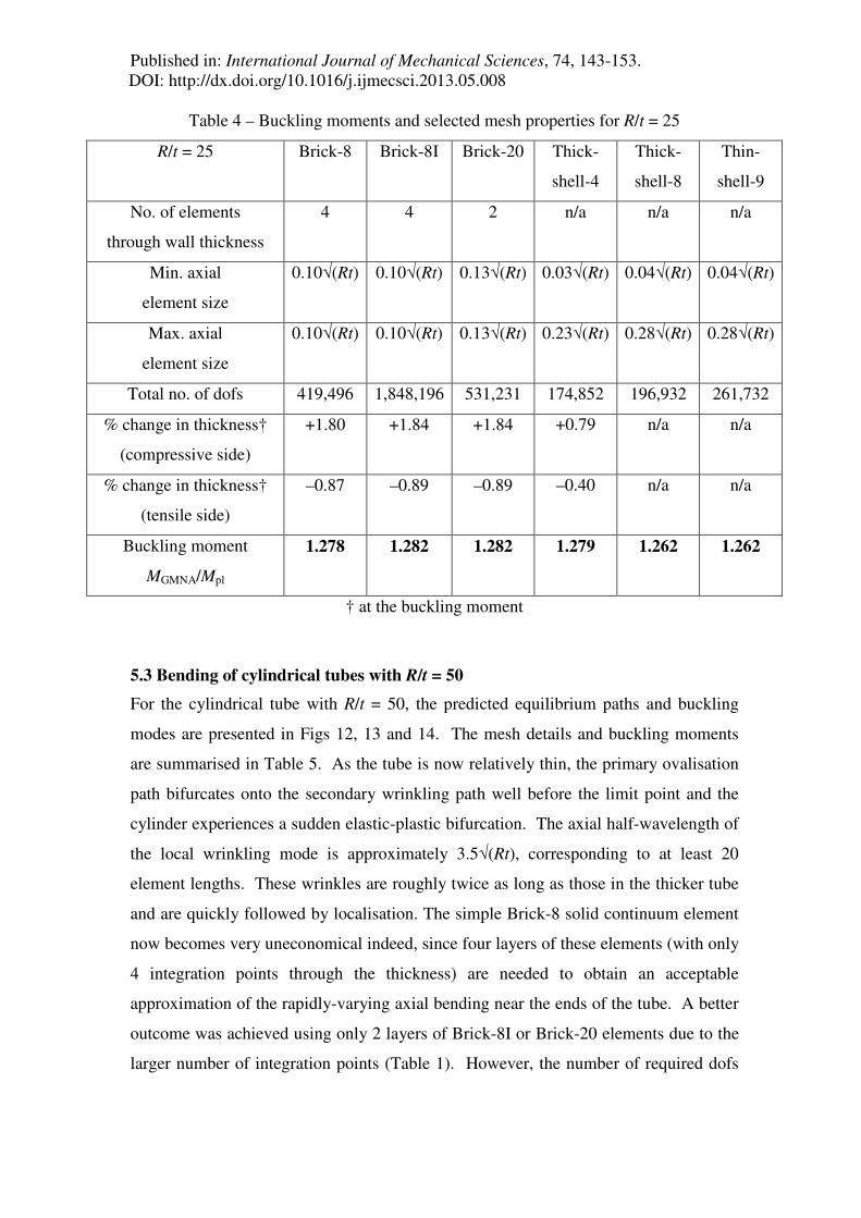
Table 4 – Buckling moments and selected mesh properties for R/t = 25
R/t = 25 Brick-8 Brick-8I Brick-20 Thick-
shell-4
Thick-
shell-8
Thin-
shell-9
No. of elements
through wall thickness
4 4 2 n/a n/a n/a
Min. axial
element size
0.10√(Rt) 0.10√(Rt) 0.13√(Rt) 0.03√(Rt) 0.04√(Rt) 0.04√(Rt)
Max. axial
element size
0.10√(Rt) 0.10√(Rt) 0.13√(Rt) 0.23√(Rt) 0.28√(Rt) 0.28√(Rt)
Total no. of dofs 419,496 1,848,196 531,231 174,852 196,932 261,732
% change in thickness†
(compressive side)
+1.80 +1.84 +1.84 +0.79 n/a n/a
% change in thickness†
(tensile side)
–0.87 –0.89 –0.89 –0.40 n/a n/a
Buckling moment
MGMNA/Mpl
1.278 1.282 1.282 1.279 1.262 1.262
† at the buckling moment
5.3 Bending of cylindrical tubes with R/t = 50
For the cylindrical tube with R/t = 50, the predicted equilibrium paths and buckling
modes are presented in Figs 12, 13 and 14. The mesh details and buckling moments
are summarised in Table 5. As the tube is now relatively thin, the primary ovalisation
path bifurcates onto the secondary wrinkling path well before the limit point and the
cylinder experiences a sudden elastic-plastic bifurcation. The axial half-wavelength of
the local wrinkling mode is approximately 3.5√(Rt), corresponding to at least 20
element lengths. These wrinkles are roughly twice as long as those in the thicker tube
and are quickly followed by localisation. The simple Brick-8 solid continuum element
now becomes very uneconomical indeed, since four layers of these elements (with only
4 integration points through the thickness) are needed to obtain an acceptable
approximation of the rapidly-varying axial bending near the ends of the tube. A better
outcome was achieved using only 2 layers of Brick-8I or Brick-20 elements due to the
larger number of integration points (Table 1). However, the number of required dofs

Published in: International Journal of Mechanical Sciences, 74, 143-153. DOI: http://dx.doi.org/10.1016/j.ijmecsci.2013.05.008
in all solid element cases is almost three times that of the simplest shell elements, with
no noticeable advantage in the accuracy of the solution.
Fig. 12 – Normalised moment-curvature curves for R/t = 50
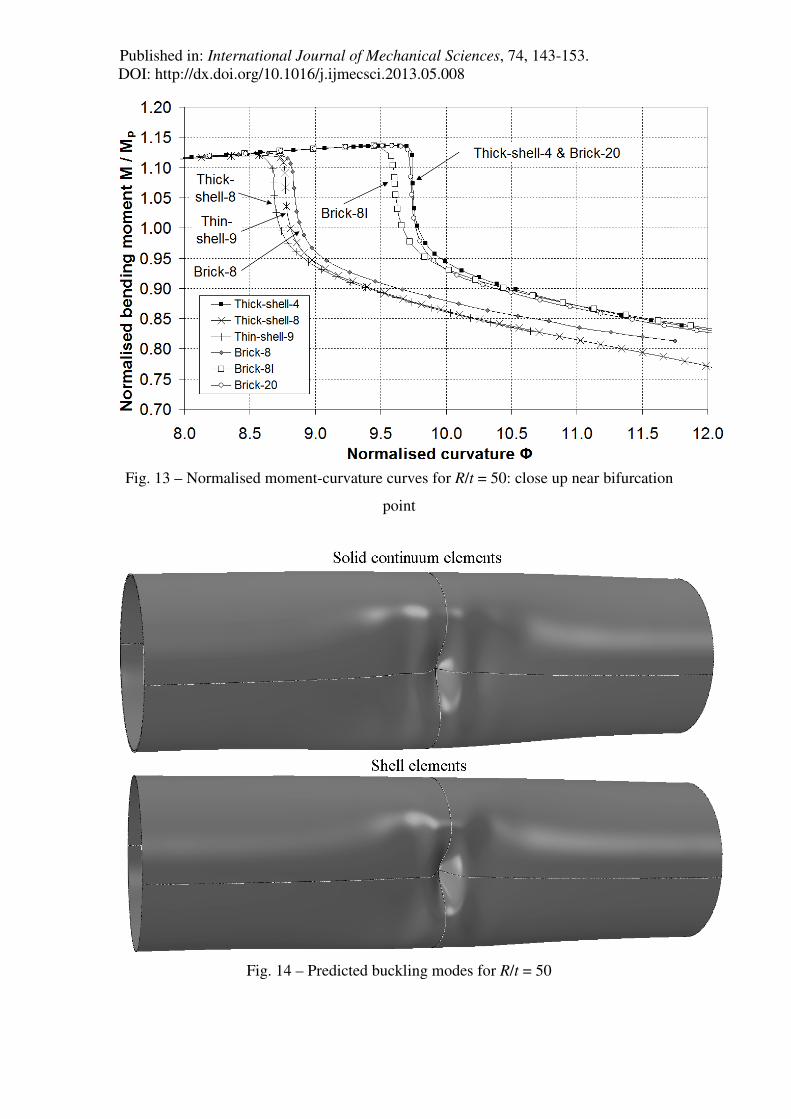
Published in: International Journal of Mechanical Sciences, 74, 143-153. DOI: http://dx.doi.org/10.1016/j.ijmecsci.2013.05.008
Fig. 13 – Normalised moment-curvature curves for R/t = 50: close up near bifurcation
point
Fig. 14 – Predicted buckling modes for R/t = 50

Published in: International Journal of Mechanical Sciences, 74, 143-153. DOI: http://dx.doi.org/10.1016/j.ijmecsci.2013.05.008
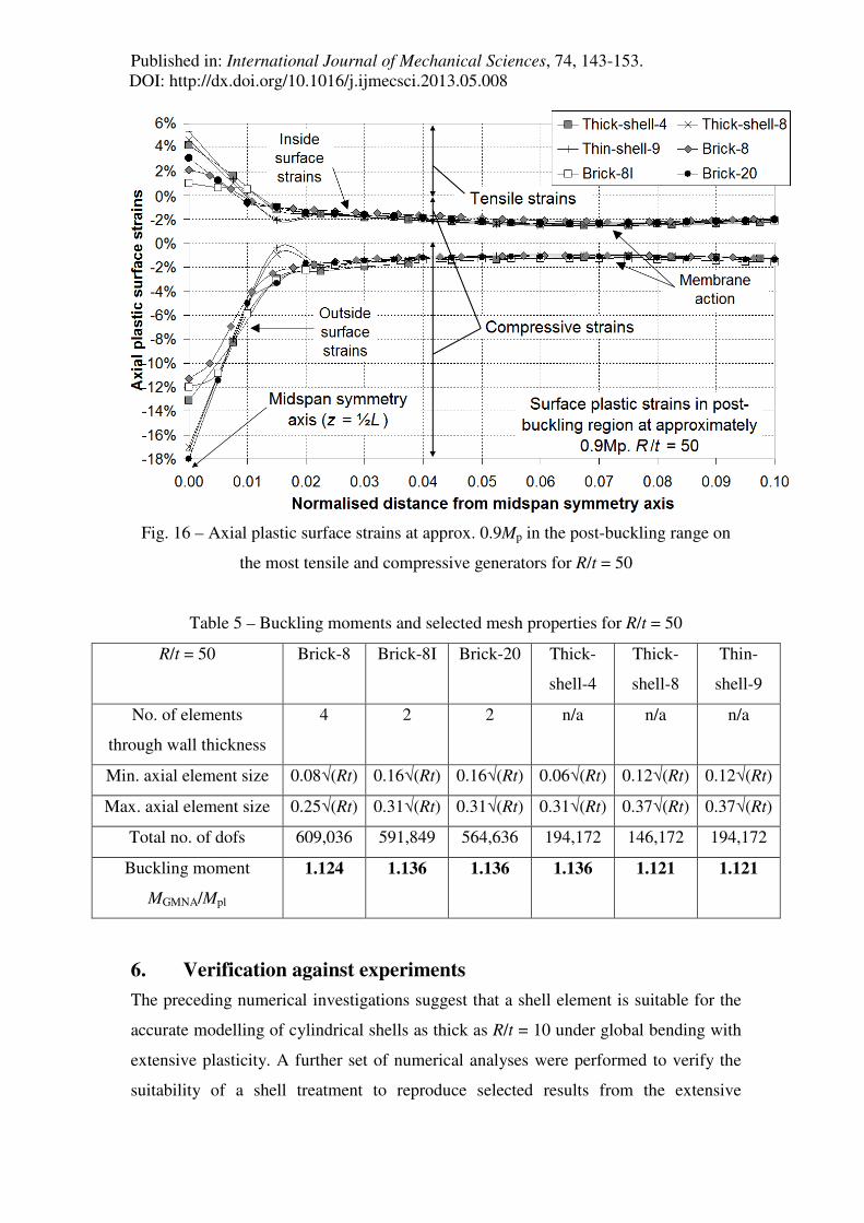
The axial membrane strains at midspan follow the same circumferential variation for
R/t = 50 as for R/t = 25 (Fig. 11) except that the peak compressive strain at the instant
before bifurcation is now less than 2%. The axial variation on the compressed
generator at θ = 0° (Fig. 15) shows that plastic strains are low everywhere before
buckling, the largest variation being caused by local shell bending at the end
boundaries. However, the local curvatures associated with the axial wrinkling mode
become significant in the post-buckling range. At a post-buckling moment of 0.9Mp,
the peak axial plastic strains reach 18% on the compressed outer surface, a value that
depends on the element (Fig. 16). A finite strain formulation may thus be necessary if
the model is required to explore ductility well into the post-buckling range and
extensive plasticity is involved.
Fig. 15 – Axial plastic membrane strains at the instant before buckling through the axis
of circumferential symmetry at θ = 0° for R/t = 50
Published in: International Journal of Mechanical Sciences, 74, 143-153. DOI: http://dx.doi.org/10.1016/j.ijmecsci.2013.05.008
Fig. 16 – Axial plastic surface strains at approx. 0.9Mp in the post-buckling range on
the most tensile and compressive generators for R/t = 50
Table 5 – Buckling moments and selected mesh properties for R/t = 50
R/t = 50 Brick-8 Brick-8I Brick-20 Thick-
shell-4
Thick-
shell-8
Thin-
shell-9
No. of elements
through wall thickness
4 2 2 n/a n/a n/a
Min. axial element size 0.08√(Rt) 0.16√(Rt) 0.16√(Rt) 0.06√(Rt) 0.12√(Rt) 0.12√(Rt)
Max. axial element size 0.25√(Rt) 0.31√(Rt) 0.31√(Rt) 0.31√(Rt) 0.37√(Rt) 0.37√(Rt)
Total no. of dofs 609,036 591,849 564,636 194,172 146,172 194,172
Buckling moment
MGMNA/Mpl
1.124 1.136 1.136 1.136 1.121 1.121
6. Verification against experiments
The preceding numerical investigations suggest that a shell element is suitable for the
accurate modelling of cylindrical shells as thick as R/t = 10 under global bending with
extensive plasticity. A further set of numerical analyses were performed to verify the
suitability of a shell treatment to reproduce selected results from the extensive
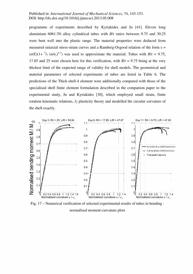
Published in: International Journal of Mechanical Sciences, 74, 143-153. DOI: http://dx.doi.org/10.1016/j.ijmecsci.2013.05.008
programme of experiments described by Kyriakides and Ju [41]. Eleven long
aluminium 6061-T6 alloy cylindrical tubes with R/t ratios between 9.75 and 30.25
were bent well into the plastic range. The material properties were deduced from
measured uniaxial stress-strain curves and a Ramberg-Osgood relation of the form ε =
(σ/E)(1+ 3/7 (σ/σy)n-1) was used to approximate the material. Tubes with R/t = 9.75,
17.85 and 25 were chosen here for this verification, with R/t = 9.75 being at the very
thickest limit of the expected range of validity for shell models. The geometrical and
material parameters of selected experiments of tubes are listed in Table 6. The
predictions of the Thick-shell-4 element were additionally compared with those of the
specialised shell finite element formulation described in the companion paper to the
experimental study, Ju and Kyriakides [30], which employed small strain, finite
rotation kinematic relations, J2 plasticity theory and modelled the circular curvature of
the shell exactly.
Fig. 17 – Numerical verification of selected experimental results of tubes in bending -
normalised moment-curvature plots
Published in: International Journal of Mechanical Sciences, 74, 143-153. DOI: http://dx.doi.org/10.1016/j.ijmecsci.2013.05.008
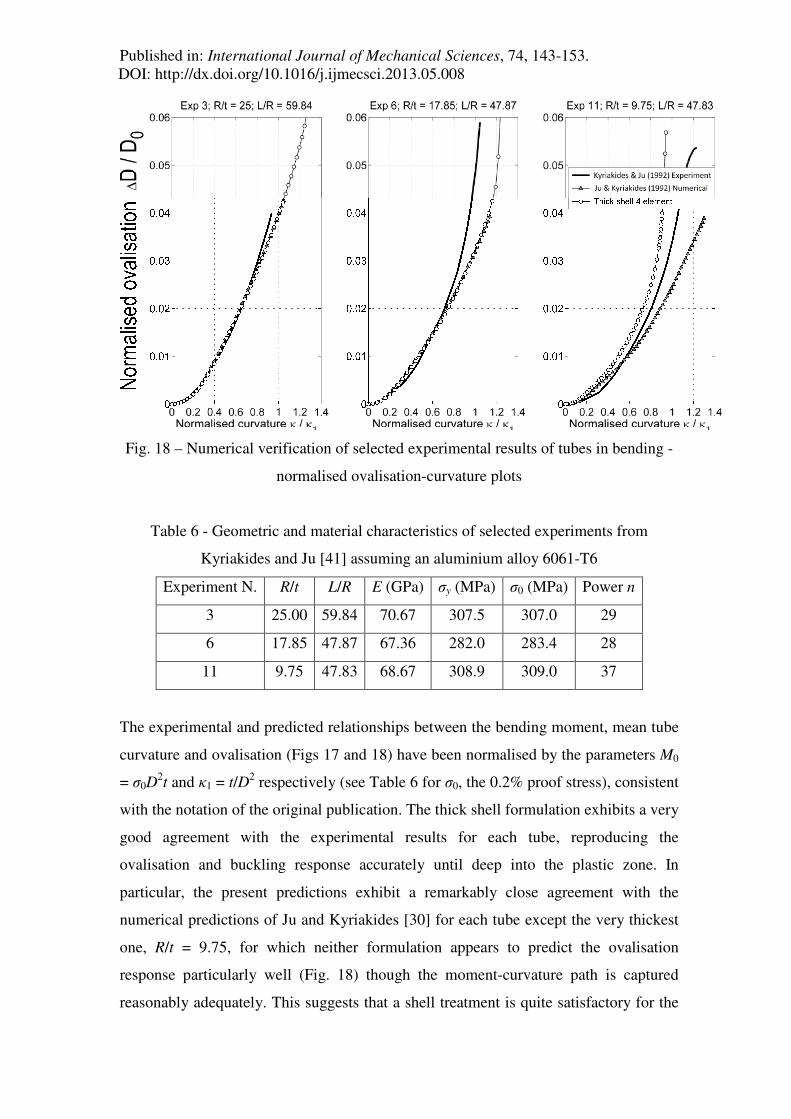
Fig. 18 – Numerical verification of selected experimental results of tubes in bending -
normalised ovalisation-curvature plots
Table 6 - Geometric and material characteristics of selected experiments from
Kyriakides and Ju [41] assuming an aluminium alloy 6061-T6
Experiment N. R/t L/R E (GPa) σy (MPa) σ0 (MPa) Power n
3 25.00 59.84 70.67 307.5 307.0 29
6 17.85 47.87 67.36 282.0 283.4 28
11 9.75 47.83 68.67 308.9 309.0 37
The experimental and predicted relationships between the bending moment, mean tube
curvature and ovalisation (Figs 17 and 18) have been normalised by the parameters M0
= σ0D2t and κ1 = t/D2 respectively (see Table 6 for σ0, the 0.2% proof stress), consistent
with the notation of the original publication. The thick shell formulation exhibits a very
good agreement with the experimental results for each tube, reproducing the
ovalisation and buckling response accurately until deep into the plastic zone. In
particular, the present predictions exhibit a remarkably close agreement with the
numerical predictions of Ju and Kyriakides [30] for each tube except the very thickest
one, R/t = 9.75, for which neither formulation appears to predict the ovalisation
response particularly well (Fig. 18) though the moment-curvature path is captured
reasonably adequately. This suggests that a shell treatment is quite satisfactory for the
Published in: International Journal of Mechanical Sciences, 74, 143-153. DOI: http://dx.doi.org/10.1016/j.ijmecsci.2013.05.008
nonlinear buckling analysis of very thick cylindrical tubes with a complex material
definition and extensive plasticity.
7. Conclusions
The following conclusions may be drawn from this study:
1) The classical literature is surprisingly vague about when a shell structure may be
analysed using a thin shell theory approximation. Current advice is based on order-of-
magnitude assessments of analytical solutions to elastic problems that have relatively
simple mechanics.
2) A thin shell treatment was found to give reasonably accurate estimates of the elastic-
plastic strain hardening buckling moment under uniform bending for cylinders as thick
as R/t = 10. However, this is insufficient to model the ductility of the response well,
and in some cases this may also be an important criterion of failure. A thick shell
treatment is more appropriate in such cases.
3) The predictions produced by a finite strain thick shell formulation were found to be
of comparable accuracy to those produced by a solid continuum formulation for
cylinders as thick as R/t = 10. For such very thick cylinders, however, non-standard
modelling techniques may need to be applied to ensure convergence. It is
recommended that the second order or enhanced solid continuum elements are used to
model such thick tubes.
4) It becomes uneconomical to use solid continuum elements for the analysis of
uniform cylindrical tubes under global bending when R/t ≥ 25, as several layers of such
elements are necessary to correctly model the through-thickness bending at the end
boundaries. Finite strain shell elements should be used instead, with no noticeable loss
in accuracy. This conclusion may of course no longer be valid for the analysis of
composite shells, which were not considered here.
Published in: International Journal of Mechanical Sciences, 74, 143-153. DOI: http://dx.doi.org/10.1016/j.ijmecsci.2013.05.008
5) Small strain shell elements may be applied with confidence for R/t ≥ 50, except
when the goal is to predict the ductility of the behaviour far into the post-buckling
range.
6) The finite strain thick shell element was carefully verified against selected
experimental results of tubes in bending as reported in Kyriakides and Ju [41]. The
predictions exhibit a remarkably close agreement for tubes as thick as R/t = 9.75. This
suggests that thick shell elements may give realistic results even for very thick and
long cylinders and that it is unnecessary to model such tubes using computationally-
expensive solid continuum elements or more specialised finite element formulations.
Acknowledgements
The authors would like to thank Dr Lei Chen who completed his PhD at The
University of Edinburgh in 2011 and whose work laid much of the foundation and
background to the material presented in this paper. The work itself was carried out as
part of the EU Combitube research project funded by the European Commission, grant
number RFSR-CT-2011-00034.
References
[1] Bushnell D. (1985). “Computerized buckling analysis of shells” Martinus Nijhoff
Publishers.
[2] Donnell L.H. (1933). "Stability of thin-walled tubes under torsion" NACA Report
No. 479.
[3] Timoshenko S. P. (1953). “History of strength of materials” McGraw-Hill Book
Company.
[4] Novozhilov V. V. (1964). "The theory of thin shells" Translation of the 2nd
Russian edition by P.G. Lowe, ed J.R.M. Radok, P. Noordhoff Ltd, Groningen-
Holland.
[5] Calladine C. R. (1983). “Theory of shell structures” Cambridge University Press.

Published in: International Journal of Mechanical Sciences, 74, 143-153. DOI: http://dx.doi.org/10.1016/j.ijmecsci.2013.05.008
[6] Brush D.O. & Almroth B.O. (1975). “Buckling of bars, plates and shells” McGraw-
Hill.
[7] Seide P. (1975). "Small elastic deformations of thin shells" Noordhoff, Leyden,
Holland.
[8] Reissner E. (1945). “The effect of transverse shear deformation on the bending of
elastic plates” J. Appl. Mech, 12, A69-A77.
[9] Mindlin R. D. (1951). “Influence of rotary inertia and shear on flexural motions of
isotropic elastic plates” J. Appl. Mech, 18, 31-38.
[10] Mushkelishvili N.I. (1953). “Some basic problems in the mathematical theory of
elasticity” 3rd. Ed. P. Noordhoff Ltd., Groningen-Holland.
[11] Green A.E. & Zerna W. (1968). "Theoretical elasticity" Oxford University Press.
[12] Timoshenko S. P. & Goodier J.N. (1970). “Theory of Elasticity” McGraw-Hill
International Editions.
[13] Ramm E. (2000). "From Reissner plate theory to three dimensions in large
deformation shell analyses" ZAMM Zeitschrift für Angewandte Mathematik und
Mechanik, 80(1), 61-68.
[14] Flügge W. (1975). “Statik und Dynamik der Schalen” Springer-Verlag.
[15] Timoshenko S. P. & Woinowsky-Krieger S. (1959). “Theory of plates and shells”
McGraw-Hill International Editions.
[16] Bushnell D. (1984). “Computerized analysis of shells - governing equations”
Computers & Structures, 18(3), 471-536.

Published in: International Journal of Mechanical Sciences, 74, 143-153. DOI: http://dx.doi.org/10.1016/j.ijmecsci.2013.05.008
[17] ABAQUS (2011). “ABAQUS Version 6.10.1” Dassault Systèmes Simulia Corp.,
Providence, RI, USA.
[18] Stephens W.B., Starnes J.H. Jr & Almroth B.O. (1975). "Collapse of long
cylindrical shells under combined bending and pressure loads" AIAA Journal, 13(1),
20-25.
[19] Gellin S. (1980). "The plastic buckling of long cylindrical shells under pure
bending" International Journal of Solids and Structures, 10, 397-407.
[20] Kyriakides S. & Shaw P.K. (1982). “Response and stability of elastoplastic
circular pipes under combined bending and external pressure” Int. J. Solids and
Structures, 18(11), 957-973.
[21] Shaw P.K. & Kyriakides S. (1985). “Inelastic analysis of thin-walled tubes under
cyclic bending” Int. J. Solids and Structures, 21(11), 1073-1100.
[22] Chen L., Doerich C. and Rotter J.M. (2008) “A study of cylindrical shells under
global bending in the elastic-plastic range”, Steel Construction - Design and Research,
Stahlbau, 1(1), 59-65.
[23] Brazier L. G. (1927). “On the flexure of thin cylindrical shells and other 'thin
sections'” Proc. Roy. Soc. London Series A, 116, 104-114.
[24] Mathon C. & Limam A. (2006). "Experimental collapse of thin cylindrical shells
submitted to internal pressure and pure bending" Thin-Walled Structures¸ 44, 39-50.
[25] Sherman D.R. (1976). "Test of circular steel tubes in bending" ASCE J. Struct.
Div., 102(11), 2181-2195.

Published in: International Journal of Mechanical Sciences, 74, 143-153. DOI: http://dx.doi.org/10.1016/j.ijmecsci.2013.05.008
[26] Row D., Chan E. & Langner C.G. (1987). "Prediction of pipe collapse under
external pressure, axial load and bending" Offshore and arctic pipelines, J. S. Chung
and K. Karal (eds), ASME, New York.
[27] Karamanos S.A. & Tassoulas J.L. (1991). “Stability of inelastic tubes under
external pressure and bending” ASCE J. of Eng. Mech., 117(12), 2845-2861.
[28] Seide P. & Weingarten V.I. (1961). "On the buckling of circular cylindrical shells
under pure bending" Journal of Applied Mechanics, 28(1), 112-116.
[29] Chen Y.N. & Kempner J. (1976). "Buckling of oval cylindrical shells under
compression and asymmetric bending" AIAA Journal, 14, 1235-1240.
[30] Ju G.T. & Kyriakides S. (1992). "Bifurcation and localization instabilities in
cylindrical shells under bending - II. Predictions" International Journal of Solids and
Structures, 29(9), 1143-1171,
[31] Karamanos S.A. (2002). “Bending instabilities of elastic tubes” Int. J. Solids and
Structures, 39, 2059-2085.
[32] Chen L. (2011). “Buckling of circular steel cylindrical shells under different
loading conditions” PhD Thesis, The University of Edinburgh.
[33] Ades C.S. (1957). "Bending strength of tubing in the plastic range" J.
Aeronautical Sci., 24, 605-610.
[34] Reissner E. (1959). "On finite bending of pressurised tubes" Journal of Applied
Mechanics, ASME 26, 386-392.
[35] Axelrad E.L. (1965). "Refinement of buckling-load analysis for tube flexure by
way of considering practical deformation" (Izvestiya Akademii Nauk SSSR, Otdelenie
Teknicheskikh Nauk). Mekhanika i Mashinostroenie, 4, 133-139 (in Russian).

Published in: International Journal of Mechanical Sciences, 74, 143-153. DOI: http://dx.doi.org/10.1016/j.ijmecsci.2013.05.008
[36] Kempner J. & Chen C.Y. (1974). "Buckling and initial post-buckling of oval
cylindrical shells under combined axial compression and bending" Transactions of the
New York Academy of Sciences, 171-191.
[37] Kedward K.T. (1978). "Nonlines collapse of thin-walled composite cylinders
under flexural loading." Proceedings of the 2nd Int. Conf. on Composite Materials
(Toronto), Metallurgical Society of AIME, Warrendale, PA, 353-365.
[38] Needleman A. (1982). "Finite elements for finite strain plasticity problems" In:
Lee E.H., Mallet R.L. (eds), Plasticity of Metals at Finite Strain: Theory, Experiment
and Computation. Rensselaer Polytechnic Institute, Troy, NY, 387-436.
[39] Hill R. (1950). "The mathematical theory of plasticity" Oxford University Press.
[40] Corona E. & Kyriakides S. (1988). “On the collapse of inelastic tubes under
combined bending and pressure” Int. J. Solids and Structures, 24(5), 505-535.
[41] Kyriakides S. & Ju. G.T. (1992). "Bifurcation and localization instabilities in
cylindrical shells under bending - I. Experiments" International Journal of Solids and
Structures, 29(9), 1117-1142,
[42] Karamanos S.A. & Tassoulas J.L. (1996a). "Tubular members. I: Stability
analysis and preliminary results" ASCE J. of Eng. Mech., 122(1), 64-71.
[43] Karamanos S.A. & Tassoulas J.L. (1996b). "Tubular members. II: Local buckling
and experimental verification" ASCE J. of Eng. Mech., 122(1), 72-78.
[44] Houliara S. & Karamanos S. A. (2006). "Buckling and post-buckling of long
pressurised elastic thin-walled tubes under in-plane bending" International Journal of
Nonlinear Mechanics, 41, 491-511.
Published in: International Journal of Mechanical Sciences, 74, 143-153. DOI: http://dx.doi.org/10.1016/j.ijmecsci.2013.05.008
[45] Houliara S. & Karamanos S. A. (2010). "Stability of long transversely-isotropic
elastic cylindrical shells under bending" International Journal of Solids and Structures,
47, 10-24.
[46] Jayadevan K.R., Østby E. & Thaulow C. (2004). "Fracture response of pipelines
subjected to large plastic deformation under tension" International Journal of Pressure
Vessels and Piping, 81, 771-783.
[47] Østby E., Jayadevan K.R. & Thaulow C. (2005). “Fracture response of pipelines
subject to large plastic deformation under bending” Int. J. Pressure Vessels & Piping,
82, 201-215.
[48] Corona E., Lee L-H & Kyriakides S. (2006). "Yield anisotropy effects on bucking
of circular tubes under bending" Int. J. Solids and Structures, 43, 7099-7118.
[49] Ramberg W. & Osgood W.R. (1943). "Description of stress-strain curves by three
parameters" National Advisory Committee on Aeronautics, Technical Note 902.
[50] Limam A., Lee-L-H & Kyriakides S. (2010). "On the collapse of dented tubes
under combined bending and internal pressure" International Journal of Mechanical
Sciences, 55, 1-12.
[51] Limam A., Lee-L-H, Corona E. & Kyriakides S. (2012). "Inelastic wrinkling and
collapse of tubes under combined bending and internal pressure" International Journal
of Mechanical Sciences, 52, 637-647.
[52] EN 1993-1-6 (2007). “Eurocode 3: design of steel structures, Part 1-6: strength
and stability of shell structures.” Comité Européen de Normalisation, Brussels.
[53] Riks E. (1979). “An incremental approach to the solution of snapping and
buckling problems” Int. J. Solids. Struct., 15, 529-551.
Published in: International Journal of Mechanical Sciences, 74, 143-153. DOI: http://dx.doi.org/10.1016/j.ijmecsci.2013.05.008
[54] Timoshenko S.P. & Gere J.M. (1961). “Theory of Elastic Stability”, 2nd edn,
McGraw-Hill, New York.
[55] Rotter J.M. (2004). "Buckling of cylindrical shells under axial compression"
Chapters and 2 in Buckling of Thin Metal Shells, Eds J.G. Teng & J.M. Rotter, Spon,
London, 1-87.
[56] Batoz J.L., Bathe K.J. & Ho L.W. (1980). "A study of three-node triangular plate
bending elements" International Journal for Numerical Methods in Engineering, 15,
1771-1821.
[57] Cook R.D., Malkus D.S., Plesha M. E. & Witt R.J. (2002). “Concepts and
applications of finite element analysis” 4th Ed., John Wiley & Sons.
[58] Simo J.C. & Rifai M.S. (1990). "A class of assumed strain methods and the
methods of incompatible modes" International Journal for Numerical Methods in
Engineering, 29, 1595-1638.
[59] Simo J.C. & Armero F. (1992). "Geometrically nonlinear enhanced strain mixed
methods and the method of incompatible modes" International Journal for Numerical
Methods in Engineering, 33, 1413-1449.
[60] Agah-Tehrani A, Lee E. H., Mallett R. L. & Onat E.T. (1986). "The theory of
elastic-plastic deformation at finite strain with induced anisotropy modelled as
combined isotropic-kinematic hardening" Metal Forming Report, Rensselaer
Polytechnic Institute, Troy, New York.
[61] Zienkiewicz O.C., Taylor R.L. & Too J.M. (1971). "Reduced integration
technique in general analysis of plates and shells" IJNME 3, 275-290.
[62] Laulusa A., Bauchau O.A., Choi J.Y., Tan V.B.C. & Li L. (2005). “Evaluation of
some shear deformable shell elements” Int. J. Solids and Structures, 43, 5033-5054.

Published in: International Journal of Mechanical Sciences, 74, 143-153. DOI: http://dx.doi.org/10.1016/j.ijmecsci.2013.05.008
[63] Schafer B.W., Li Z. & Moen C.D. (2010). "Computational modelling of cold-
formed steel" Thin-Walled Structures, 48, 752-762.
[64] MacNeal R. (1994). "Finite Elements: Their Design and Application" Marcel
Dekker, New York.
[65] Song C.Y., Teng J.G. & Rotter J.M. (2004). "Imperfection sensitivity of thin
elastic cylindrical shells subject to partial axial compression" International Journal of
Solids and Structures, 41, 7155-7180.
[66] Gardner L. & Nethercot D.A. (2004). "Numerical modelling of stainless steel
structural components - a consistent approach" ASCE Journal of Structural
Engineering, 130(10), 1586-1601.
[67] Panasz P. & Wisniewski K. (2008). "Nine-node shell elements with 6 dofs/node
based on two-level approximations. Part I Theory and linear tests" Finite Elements in
Analysis and Design, 44, 784-796.
[68] Moen C.D. & Schafer B.W. (2009). "Elastic buckling of thin plates with holes in
compression or bending" Thin-Walled Structures, 47, 1597-1607.
[69] Budiansky B. & Sanders J.L. (1963). "On the 'best' first-order linear shell theory"
Progress in Applied Mechanics, The Prager Anniversary Volume, Macmillan, London,
129-140.
[70] Bathe K.J., Ramm E. & Wilson E.L. (1975). "Finite element formulations for
large deformation dynamic analysis." International Journal for Numerical Methods in
Engineering, 9(2), 353-386.
[71] Ramm E., Braun M. & Bischoff M. (1995). "Higher order nonlinear shell
formulations: theory and applications" Journal of the International Association for
Shell and Spatial Structures, 36(119), 145-152.

Published in: International Journal of Mechanical Sciences, 74, 143-153. DOI: http://dx.doi.org/10.1016/j.ijmecsci.2013.05.008
[72] Bischoff M. & Ramm E. (1997). "Shear deformable shell elements for large
strains and rotations" International Journal for Numerical Methods in Engineering,
40(23), 4427-4449.
[73] Neal B.G. (1963). "The plastic methods of structural analysis" Chapman and Hall.
[74] Bruneau M., Ung C.M. & Whittaker A. (1998). "Ductile design of steel
structures" McGraw Hill.
[75] Yamaki N. (1984). “Elastic Stability of Circular Cylindrical Shells”, North
Holland, Elsevier Applied Science Publishers, Amsterdam.
[76] Rotter J.M. & Teng J.G. (1989). "Elastic stability of cylindrical shells with weld
depressions" ASCE Journal of Structural Engineering, 115(5), 1244-1263.
[77] Heyman J. (1977). "Equilibrium of shell structures" Oxford University Press.
FIGURE CAPTIONS
Fig. 1 – Qualitative illustration of the equilibrium paths in cylinders with L/R = 7 and a
strain hardening material law (cylinders of different length exhibit similar qualitative
features)
Fig. 2 – Assumed engineering stress-strain relation, with 2.5% linear strain hardening
Fig. 3 – Features of the numerical model for both shell and solid elements
Fig. 4 – Normalised moment-curvature curves for R/t = 10
Fig. 5 – Normalised moment-curvature curves for R/t = 10: close-up near limit point
Fig. 6 – Predicted buckling modes for R/t = 10

Published in: International Journal of Mechanical Sciences, 74, 143-153. DOI: http://dx.doi.org/10.1016/j.ijmecsci.2013.05.008
Fig. 7 – Illustration of the effect of ovalisation for R/t = 10
Fig. 8 – Normalised moment-curvature curves for R/t = 25
Fig. 9 – Normalised moment-curvature curves for R/t = 25: close up near limit point
Fig. 10 – Predicted buckling modes for R/t = 25
Fig. 11 – Axial plastic membrane strains at the instant of buckling through the axis of
axial symmetry (½L - midspan)
Fig. 12 – Normalised moment-curvature curves for R/t = 50
Fig. 13 – Normalised moment-curvature curves for R/t = 50: close up near bifurcation
point
Fig. 14 – Predicted buckling modes for R/t = 50
Fig. 15 – Axial plastic membrane strains at the instant before buckling through the axis
of circumferential symmetry at θ = 0° for R/t = 50
Fig. 16 – Axial plastic surface strains at approx. 0.9Mp in the post-buckling range on
the most tensile and compressive generators for R/t = 50
Fig. 17 – Numerical verification of selected experimental results of tubes in bending -
normalised moment-curvature plots
Fig. 18 – Numerical verification of selected experimental results of tubes in bending -
normalised ovalisation-curvature plots
TABLE CAPTIONS

Published in: International Journal of Mechanical Sciences, 74, 143-153. DOI: http://dx.doi.org/10.1016/j.ijmecsci.2013.05.008
Table 1 – Selected 3D solid continuum finite element formulations with ABAQUS
implementations
Table 2 – Selected 3D structural shell finite element formulations with ABAQUS
implementation
Table 3 – Buckling moments and selected mesh properties for R/t = 10
Table 4 – Buckling moments and selected mesh properties for R/t = 25
Table. 5 – Buckling moments and selected mesh properties for R/t = 50
Table 6 - Geometric and material characteristics of selected experiments from
Kyriakides and Ju [41] assuming an aluminium alloy 6061-T6