
Solar Mirrors - InTech - Open Science Open Minds | InTechOpen
26
6 Solar Mirrors Rafael Almanza and Iván Martínez Universidad Nacional Autónoma de México, Universidad Autónoma del Estado de México México 1. Introduction Solar concentration utilises devices that range from simple designs, such as flat solar collectors surrounded by mirrors, to solar concentrators that employ a parabolic trough, a parabolic dish or a central tower surrounded by heliostats to achieve temperatures of a few hundred to several thousand degrees Celsius. All of these designs use flat or curved mirrors and several decades’ worth of development have resulted in improved specular reflectance, half-life and cost. First surface mirrors use reflective material deposited on a substrate (glass or plastic) and coated with a protective, transparent film to eliminate abrasion and corrosion. In second surface mirrors, silver or aluminium is deposited on the back of the transparent substrate. The development of these mirrors, in particular second surface mirrors, have been reviewed by numerous authors, including Dennis (1979), Ashley et al. (1988), Jorgensen et al. (1994), Schissel et al. (1994), Kennedy and Jorgensen (1994), Martin et al. (1994), Fend et al. (2000, 2003), Kennedy et al. (2005), and Kearney and Price (2005). The 3M ® thin mirror (ECP-305), which employs silver deposited on acrylic (PMMA), has been used for several years at the Solar Power Plant Engineering Institute (National University of Mexico), where numerous problems have been identified. In particular, cracks developed rapidly over the acrylic (after 1 year) in Mexico City, which is a very polluted city, and the acrylic adhered poorly to the silver, resulting in corrosion and the formation of a tunnel in the mirror during the wet season. Thin silver mirrors (1 mm or less) exhibit additional limitations, such as weakness, manoeuvrability and high cost, as discussed by Kennedy et al. (1996). Kearney and Price (2005) discussed the behaviour of the seven commercial silver mirrors, including a silver-coated first surface mirror. The performance, based solely on accelerated time, produced a specular reflection coefficient above 95% after the equivalent of 5 years of exposure and a reflection above 90% after 6 years. Compared to silver, aluminium is the most abundant metal, is relatively inexpensive and is the most widely used non-ferrous metal. Aluminium reflectors generally provide an initial reflection (of solar radiation) of 85-91%, exhibit good mechanical properties and are easy to recycle. However, exposure to air causes serious degradation of the optical properties of unprotected aluminium surfaces in just a couple of years. Compared to untreated aluminium, anodised aluminium exhibits improved behaviour because of the Al 2 O 3 layer, www.intechopen.com
Transcript of Solar Mirrors - InTech - Open Science Open Minds | InTechOpen
6
Solar Mirrors
Rafael Almanza and Iván Martínez Universidad Nacional Autónoma de México,
Universidad Autónoma del Estado de México México
1. Introduction
Solar concentration utilises devices that range from simple designs, such as flat solar collectors surrounded by mirrors, to solar concentrators that employ a parabolic trough, a parabolic dish or a central tower surrounded by heliostats to achieve temperatures of a few hundred to several thousand degrees Celsius. All of these designs use flat or curved mirrors and several decades’ worth of development have resulted in improved specular reflectance, half-life and cost.
First surface mirrors use reflective material deposited on a substrate (glass or plastic) and coated with a protective, transparent film to eliminate abrasion and corrosion. In second surface mirrors, silver or aluminium is deposited on the back of the transparent substrate.
The development of these mirrors, in particular second surface mirrors, have been reviewed by numerous authors, including Dennis (1979), Ashley et al. (1988), Jorgensen et al. (1994), Schissel et al. (1994), Kennedy and Jorgensen (1994), Martin et al. (1994), Fend et al. (2000, 2003), Kennedy et al. (2005), and Kearney and Price (2005).
The 3M® thin mirror (ECP-305), which employs silver deposited on acrylic (PMMA), has been used for several years at the Solar Power Plant Engineering Institute (National University of Mexico), where numerous problems have been identified. In particular, cracks developed rapidly over the acrylic (after 1 year) in Mexico City, which is a very polluted city, and the acrylic adhered poorly to the silver, resulting in corrosion and the formation of a tunnel in the mirror during the wet season. Thin silver mirrors (1 mm or less) exhibit additional limitations, such as weakness, manoeuvrability and high cost, as discussed by Kennedy et al. (1996). Kearney and Price (2005) discussed the behaviour of the seven commercial silver mirrors, including a silver-coated first surface mirror. The performance, based solely on accelerated time, produced a specular reflection coefficient above 95% after the equivalent of 5 years of exposure and a reflection above 90% after 6 years.
Compared to silver, aluminium is the most abundant metal, is relatively inexpensive and is the most widely used non-ferrous metal. Aluminium reflectors generally provide an initial reflection (of solar radiation) of 85-91%, exhibit good mechanical properties and are easy to recycle. However, exposure to air causes serious degradation of the optical properties of unprotected aluminium surfaces in just a couple of years. Compared to untreated aluminium, anodised aluminium exhibits improved behaviour because of the Al2O3 layer,
www.intechopen.com

Solar Power
80
which protects the metal from further reaction. For this reason, anodising is often used to prolong the life of aluminium reflectors. Nonetheless, high purity aluminium must be used in order for the mirror to obtain good reflectance. The Alanod MIRO® brand manufactures this type of aluminium mirror utilising highly reflective aluminium foil. However, SiO2 protects against abrasion and improves corrosion resistance, making it an attractive candidate for the development of aluminium mirrors; however, its economic feasibility must be demonstrated.
One of the advantages of aluminium first surface mirrors is that they do not require glass with low iron content. However, first surface mirrors made of aluminium and silver have not been thoroughly investigated as alternatives to solar concentrators.
Mirror Type Reflectance s(0.01)
Time [years]
Comments
Initial Final
FEK-244 0.86 0.72 16 Tunnel effect and corrosion
Kingston 0.86 0.49 16 Very poor reflectance
PMMA (3mm) Mexican Mirror
0.85 0.72 16 Poor adhesion and corrosion
ECP-305 0.95 0.92 2 Corrosion, tunnel effect and crack on PMMA
Al-first surface 0.85 0.85 2 Without important problems
ReflecTech® 0.94 0.94 2 Silver Mirror Film
Table 1. Specular reflectance of commercial mirrors after 16 years of weather exposure at the Solar Power Plant of Engineering Institute
Kennedy et al. (1996) have shown progress in aluminium mirrors (Al2O3) protected with polyethylene terephthalate (PET); the use of glass substrates and stainless steel were also reported. Morales and Ajona (1996, 1999) have developed sol-gel technology for silver mirrors and explored protection using SiO2 and different substrates. Fend et al. (2000) have explored anodised or coated aluminium sheets and report accelerated aging, Brogren et al. (2004) developed aluminium-polymer-laminated steel reflectors using stainless steel as the substrate. Almanza et al. (1992, 1995) and Martinez et al. (2000) have developed the first aluminium mirror surface using quartz (SiO2) as a protective layer and soda lime float glass. Table 1 shows the specular reflectance (200 to 2200 nm) of some commercial mirrors after 16 years (1979-1995) of exposure to the aggressive weather of Mexico City at the Solar Plant Engineering Institute (National University of Mexico). In the international literature, long-term outdoor tests are hard to find because most studies are performed in simulated weather conditions. Table 1 also shows results for the ECP-305 and the aluminium mirror first surface after two years of exposure. The tabulated results show a considerable decrease in the specular reflectance, in addition to numerous other problems, of mirrors with 16 years of exposure. An alternative product is the silver-based ReflecTech® Mirror Film, which exhibits an initial specular reflectance of 94%.
www.intechopen.com

Solar Mirrors
81
Primary aluminium mirror surfaces have also been applied to semiconductor lithography where a high reflectance (90%) is required (Hernandez et al., 2003) and high-quality mirrors are needed for different management systems to measure the distance in thermonuclear reactors (Yang et al., 2006).
2. Manufacture of mirrors for solar applications
This section reviews the utilisation of tungsten filament evaporation, electron guns, sputtering and coatings made from fluids via the sol-gel technique or chemical baths.
Filaments, electron guns (e-guns), linear magnetrons, sol-gel techniques and chemical baths have all shown promise in the deposition of thin film metals and dielectrics. In reviewing the use of these devices in Mexico, this paper presents the fabrication of aluminium first surface mirrors, in which reactive evaporation, such as the change of SiO into Si2O3 under specific oxygen conditions in a low pressure evaporator, is an important deposition method. The resulting film forms a conveniently thin and transparent layer, protecting the aluminium first surface mirror. Alternatively, quartz (SiO2) can be substituted for SiO in the protective layer.
Coatings employing substances with high melting points (metals and dielectrics) are made possible via the use of e-guns, while linear magnetrons enable the deposition of metals or dielectrics at lower temperatures by using a plasma to sputter the material (Rossnagel et al., 1990; Wasa, 1992) into larger areas. In this last case, the mirror area depends on the number and size of the available magnetrons, as well as the size of the chamber.
These devices have been used to obtain first surface solar aluminium mirrors (Almanza et al., 1992, 1995) as well as in other applications related to film deposition. Figure 1 shows some of the devices that are used to make thin films, including the vacuum chamber, which has a volume of nearly 1.5 m3.
In addition to their size, one of the problems with first surface solar mirrors is the likelihood of contamination during the evaporation process. After certain period of time of exposure to the environment, corrosion and tunnelling can degrade the mirror, especially in high humidity conditions. Nonetheless, these mirrors have been successfully used in numerous applications, including high UV reflectance measurements involved in water detoxification (Blake, 1992), as solar mirrors under natural and extreme conditions (Almanza et al., 1992, 1995) using the visible spectrum and in laser and IR applications (Haas et al., 1982).
Fig. 1. Photograph of vacuum chamber, high voltage source, and vacuum gauges
www.intechopen.com

Solar Power
82
2.1 Filaments
A single, 1 to 2 mm-diameter tungsten filament is usually used to thermally evaporate aluminium using a low voltage transformer. Because aluminium exhibits good wetting (Glang, 1970), it is possible to evaporate it directly onto the sample. It took approximately 10 minutes to evaporate a film of approximately 4000 Å using a 60 A power supply in a vacuum of 4x10⁻⁵ Torr. The cylindrical chamber employed had a diameter of 1.35 m and a length of 1 m. The filament-substrate distance was fixed at approximately 250 mm. A 99.999% purity aluminium wire was rolled around the filament and used as the evaporable substance. After the aluminium evaporation, SiO was thermally evaporated. Commercial SiO was obtained in either powder or grain form. Evaporation of the SiO was achieved using a 40 mm long, 3 mm (external diameter) tantalum tube into which three small holes of approximately 0.5 mm were bored. Heating the tube forced SiO vapours through the holes toward the glass substrate located approximately 250 mm away. The tube was heated with a current on the order of 100 A, reaching a temperature between 1150 and 1250 °C (Glang, 1970).
When the vacuum chamber was opened immediately after evaporation, observation of the mirror surface by optical microscopy revealed a SiO film with the texture of small worms. This was interpreted as a strong contraction because 1) the SiO evaporation occurred at very high temperatures even upon reaching the substrate and 2) when the chamber was opened, the cool air produced a thermal shock. This phenomenon disappeared when the mirrors were kept for several hours inside the chamber under poor vacuum conditions. The total specular reflectance of these mirrors, measured with a solar spectrum reflectometer that simulates the visible spectrum (270< <2940 nm), was approximately 0.80. When the SiO was changed into Si2O3 by reactive evaporation (during which oxygen was injected into the chamber) at a pressure of 10-4 Torr and at an evaporation rate of 3 Å/s (Haas et al., 1982; Drummeter & Haas, 1967), the reflectance increased to 0.86.
During the aluminium evaporation, some filament contamination occurred (Almanza et al., 1995). This was because Al reacted with W to form an alloy (Glang, 1970); W reacted with oxygen to form WO3 (Haas et al., 1982). As a result, pinholes (Glang & Gregor, 1970) appeared on the mirrors. These pinholes served as the initiation sites for environmental corrosion (Almanza et al., 1992). Thus, the main reason for building two e-guns was to avoid air particle contact during the opening of the chamber.
2.2 Electron guns
Our laboratory designed two electron guns, adopting existing technology to evaporate high purity aluminium and SiO or SiO2 (quartz) films. The electron guns were of the bent-beam type (Glang, 1970). Figure 2 shows the main components of such a device.
Each e-gun used a permanent Alnico magnet, one with a capacity of 450 gauss and the other with a capacity of 161 gauss. This range of magnetic fields allowed the deflection of the beam to the targets. On each e-gun, two iron vertical plates were placed in contact with the magnet in order to create an extension of the magnetic field, which deflected the electron beam to the target.
The power supply that provided the kinetic energies to the electrons operated in the range of 3.5 to 4.5 kV. Based on this energy, the magnetic rigidity (B) was estimated for the
www.intechopen.com

Solar Mirrors
83
electrons using tables from the published literature (Siegbahn, 1966). For example, for 3.5 keV, B = 202 gauss-cm and = 1.25 cm (radius of curvature); for 4.5 keV, B = 228 gauss-cm and = 1.42 cm. For the other magnet and with an average kinetic energy of 4 keV, B = 228 gauss-cm and = 1.3 cm.
Both magnets could focus the electron beam onto crucibles by orienting them via the deflection radius (Figure 2).
Fig. 2. Close-up photography of the two electron guns
The size of the beam is approximately 1 cm2. Generally, commercial e-guns produce a point beam; however, in order to achieve this, it is necessary to design and develop a complete optical study. Such a study is not necessary in the present case because it is useful to spread the beam as much as possible. The irregular beams of these e-guns are practical because they enable the evaporation of a larger target area than is generally obtained by a point beam e-gun.
Another important parameter is the tungsten filament in which the electrons are produced. This filament was adapted from a halogen car lamp. Its mean life is determined by the evaporated substances that react with it and the sputtering of the incident high-energy positive ions.
Two types of mirrors were fabricated: Al-Si2O3 and Al-Si2O3. For the evaporation of Al, a boron nitride (NB) crucible was used, thereby utilising the good wetting that occurred on the melted aluminium (Glang, 1970). A graphite crucible was used for the higher melting SiO or SiO2.
The evaporation procedure was as follows: a 1000 Å Al film was evaporated onto a clean floated glass substrate by applying 50 mA for 5 min at a pressure of 4x10⁻⁵ Torr. Then, in order to produce reactive evaporation of SiO, oxygen was introduced until a pressure of 10-4 Torr was reached, and a current of 30 mA was applied to the e-gun for one hour, so that a 3200 Å Si2O3 film was integrated. The low oxygen pressure conditions and low evaporation rate(s) required long time evaporation to assure high composition quality of the dielectric film(s).
Both e-guns are depicted in Figure 2. The pinholes were minimised due to the contaminant-free conditions inside the chamber and on the glass surface. The total specular reflectance of the mirrors was 0.89. Similar mirrors were previously reported to behave well under severe environmental conditions (Almanza et al., 1995).
www.intechopen.com
Solar Power
84
2.3 Magnetron sputtering
The goals of magnetron sputtering, depending on the magnetron size, are film purity and the capable of coating large areas. There are two kinds of magnetrons widely used for film deposition: the cylindrical type and the planar type. As with e-guns, the use of two magnetrons reduces deposition time and produces higher quality films.
In this study, a planar magnetron with a target area of 125x250 mm was used. An Al target with a thickness of 12.5 mm and a quartz target of 6.4 mm were also used. The latter was thermally bonded to the backing plate, improving thermal conductivity and allowing simple water cooling of the target. Behind the target, permanent magnets produced a magnetic field, acting as a magnetron sputter source, of several hundred gauss parallel to the cathode surface (Rossnagel et al., 1990). As a result, the electrons were forced to move in a spiral, forming a long ring over the cathode surface.
This electron confinement, in conjunction with the gas confined in the evaporator chamber, produced an argon-plasma. When DC power was used, generation of the sputtering plasma required high currents (approximately 1.5 A) due to the effect of electron accumulation in a relatively low voltage field (450V). Increasing the current density increased the sputtering rate. The electrons' spiral movement increased the collision probability (with the existing gas molecules inside the chamber). Thus, the plasma was kept at lower working pressures (from 1x10⁻⁴ to 1x10⁻² Torr).
Because of the lower density of gas molecules in this study compared to diode sputtering, the majority of sputtered atoms were less thermalised and, therefore, reached the substrate at higher energies. In both cases, the atom directions were randomised due to multiple collisions with sputtering gas particles, which improved the step coverage over all directions before arriving at the substrate (Pulker, 1999).
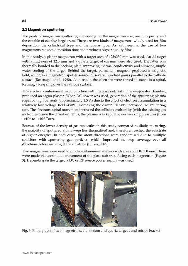
Two magnetrons were used to produce aluminium mirrors with areas of 300x600 mm. These were made via continuous movement of the glass substrate facing each magnetron (Figure 3). Depending on the target, a DC or RF source power supply was used.
Fig. 3. Photograph of two magnetrons: aluminium and quartz targets; and mirror bracket
www.intechopen.com

Solar Mirrors
85
To protect it from particle attack, the magnetron body was covered with a stainless steel shield (non-magnetic material). The distance between this cover and the target was critical and had to be maintained at approximately 5 mm. Because of this close proximity, the radiofrequency impedance between the electrode (source material) and the shield was small, and the applied energy was dissipated (and lost) across the ground connection.
Because of their sensitivity to heat, water and air, the magnets were covered by a stainless steel, water-cooled shield and embedded in a protective epoxy coating.
The DC power supply produced an output of 3 A and 600 V while feeding the magnetron with the aluminium-target (99.99% purity and 125x250 mm area). The radiofrequency power supply operated at 13.6 MHz and was capable of producing an output of 1250 W, which fed the quartz-target magnetron. Because a matching network was required between the RF power supply and the plasma chamber in the radiofrequency system, it was necessary to convert the electrical load impedance of the plasma chamber to a value of 50-70 . The matching network consisted of a tuner and a control panel. The tuner was composed of two variable, motor-driven (via an outer control circuit) air capacitors and a coil.
The radiofrequency generator (RFX-II model, from Advanced Energy) was capable of producing an output of 1250 W and maintaining a steady-state for the time period required. Their wide variety of functions were controlled by two microprocessors, providing excellent signal precision and stability. The entire device was automated and controlled using a computer. The reflected power, the forward power, the set point and the running time were all tracked.
The RF generator was connected to the tuner using a 50 Q coaxial wire. The tuner was connected to the magnetron with a Teflon®-covered copper-plated tube that was shielded with an iron pipe so that its operator was protected (note that this describes only the segment outside the evaporator chamber). The plated tube dissipated the heat easily. The length, shape and composition material of this connection had a major influence over the system performance, requiring the optimal configuration to be determined empirically. In addition, it was necessary to mount the tuner as close as possible to the magnetron and in a particular position because any changes produced different impedance values, implying a mismatch between plasma and RF generator. A bad connection produced overheating due to large amounts of dissipated energy.
The experiments were performed inside the same 1.35 m diameter cylindrical tank (Figure 4). The vacuum was produced using two different kinds of pumps: diffusion and mechanical. It was necessary to keep the working pressure in the range of 5x10⁻⁴ to 1x10⁻³ Torr in order to obtain adequate impedance and deposition rates. All the aluminium deposition processes were carried out in approximately 30 minutes. The real deposition time was 15 minutes for a 1000 Å aluminium film at 400 W and a DC Bias of -35 to -47 V. The film quality was higher than that obtained by thermal evaporation and e-gun evaporation due to pinhole minimisation, film uniformity and nucleation.
For the deposition of SiO2, the working pressure was in the range of 2x10⁻³ to 3x10⁻³ Torr. The real deposition time for a 3200 Å film was 40 minutes at 850 W and a DC Bias ranging from -55 to -60 volts.
www.intechopen.com

Solar Power
86
Fig. 4. Photograph of the vacuum chamber and diffusion pump for high vacuum
2.4 Sol-gel
Although this study did not involve the sol-gel technique, we find it pertinent to provide a comprehensive overview of this technique. The sol-gel process, also known as chemical solution deposition, is a wet-chemical technique widely used in the fields of materials science and ceramic engineering. Such methods are used primarily for the fabrication of materials originating from a chemical solution (or sol) that acts as the precursor for an integrated network (or gel) of either discrete particles or network polymers. The sol-gel technique offers a low-temperature method for synthesising materials that are either totally inorganic in nature or both inorganic and organic. The process, which is based on the hydrolysis and condensation reactions of organometallic compounds in alcoholic solutions, offers many advantages for the fabrication of coatings, including excellent control of the stoichiometries of precursor solutions, ease of compositional modifications, customisable microstructures, ease of introducing various functional groups or encapsulating sensing elements, relatively low annealing temperatures, the possibility of depositing coatings on large area substrates, and simple and inexpensive equipment (Morales & Duran, 1997). Within the past several years, a number of developments in precursor solutions, coating processes and equipment have made the sol-gel technique even more widespread.
Several methods can be used to make sol-gel coatings. Spin coating and dip coating are two basic techniques used to deposit sol-gel coatings. Spin coating produces a one-sided coating, while dip coating yields a double-sided coating. Both techniques are used in manufacturing to make different coatings and thin films.
2.5 Conclusions and suggestions
As demonstrated, the two most feasible methods for the deposition of films are e-guns and magnetron sputtering. Both methods allow metallic and dielectric evaporation with a minimum of contamination on any type of substrate, as demonstrated by the aluminium first surface solar mirrors used in this study. The method used depends on the substrate area needed. E-guns have been used for substrates with small areas (100x40 mm). Large area substrates can be deposited using several guns, resulting in uniformity of nucleation on the deposited film, an important concern in electronic and other applications. However, such devices are more costly.
www.intechopen.com
Solar Mirrors
87
In magnetrons, the metallic targets are deposited using a DC power supply employing considerable current, which is the principal limitation with regard to the area and the rate of evaporation. For dielectrics, a RF power supply is needed to perform the process, and the main problems are grounding and match-coupling; thus, it is important to avoid unnecessary equipment and ground all necessary electronic components as well as shield the RF reflectance by the substrate or any other undesirable metallic material around it.
3. Manufacturing technique
This third section discusses in detail the results obtained during the development of first surface solar mirrors, describing the main parameters involved in the implementation of each type of manufacturing technique as well as associated problems and suggestions to solve them.
3.1 Cleaning glass substrate
A clean substrate is important for the successful deposition of any film or coating. The cleaning process is required to break the links between pollutant molecules and between contaminants and the substrate (Almanza et al., 1992, 1995, 2009; Correa et al., 1998; Martinez et al., 2000). Thus, the technique chosen depends on the materials that compose the substrate, the type of pollutants and the degree of cleanliness required.
Substrate cleaning is essential, both to increase the adhesion between the film and the glass and to minimise corrosion of the mirrors. Any dust, grease, gel (i.e., the natural gel layer of glass deposited on the surface of the glass during its manufacture), oxide layers, etc., should be removed from the sheets of glass before they are placed inside the evaporation chamber.
Any contamination on the surface of the glass can cause defects in the deposited film and reduce the lifetime of the mirror. The glass can be cleaned chemically or it can be exposed to enough energy to remove the impurity, either by heating or by particle bombardment (Almanza et al., 1992, 1995, 2009; Correa et al., 1998; Martinez et al., 2000). A simple mechanical process, such as grinding, can be carefully and efficiently performed to avoid damaging the surface. The most common chemical methods are based on acid cleaning, which involves the conversion of oxides and fat-soluble compounds.
One of the most practical chemical cleaning methods employs a chromic mixture. Its use as a cleaning agent is based on its extremely strong oxidising power. For instance, the addition of chromic salts to concentrated sulphuric acid does not result in a simple solution. Instead, it produces the reaction 1.
K態Cr態O胎 + ぬH態SO替 ⟹ にK袋 + H戴O袋 + ぬHSO替貸 + にCrO戴 (1)
In the technique used for the substrate, there is always as a final treatment the so-called glow discharge that is applied within the evaporation chamber. It is a physical process that involves the exposure of glass to a glow discharge using argon or oxygen. This discharge is established between an anode (the evaporator chamber walls) and a circular aluminium cathode and close to the substrate to make cleaning more efficient. The required voltages range from 500 to 5000 V. Either AC or DC voltage can be used, although the latter is more common.
www.intechopen.com

Solar Power
88
In glow discharge cleaning, impurities are removed as a result of the following mechanisms (Brawn, 1970):
1. Direct heating by the collision of charged particles. 2. Desorption of impurities by the continuous bombardment of electrons. 3. Desorption of impurities as a result of the bombardment of low energy ions and neutral
particles. 4. Surface modification of glass by the continuous addition of the particles that make up
the plasma.
Mechanism 4 is very important, particularly for substrates containing a substantial amount of SiO2. It facilitates bridging between glass oxidisers and reactive metals, such as aluminium or chrome. It has also been observed to aid nucleation during the subsequent deposition of reflective films.
This study employed bathing in an acid solution (chromic mixture) and ion bombardment. The cleaning procedure was as follows:
- A 600x300x3 mm glass sheet was washed with commercial detergent and a soft sponge, then rinsed with water until the surface no longer felt soapy.
- The washed glass sheet was dipped in a chromic solution at 80 °C for half an hour. The composition was as follows: 24 g K2Cr2O7, 408 mL H2SO4 and 144 mL H2O.
- The glass was removed carefully from the chromic mixture and was allowed to cool for a few minutes. Next it was rinsed with water and wiped with a cloth to remove residues of the solution. Then it was dried in the atmosphere or using a hot air gun.
- The substrate was then rinsed with distilled water and placed in a container with isopropyl alcohol. Finally, the glass sheet was air dried at a temperature of 90-110 °C for 10 minutes.
The wetting of the surfaces must be examined to determine if the substrate is clean. This is known as the "water-break test" (Maissel, 1970): "If a clean substrate is removed from a container of pure water, a continuous film of water remains on the surface." This correlates with a good wetting between the substrate and water.
3.2 Sputtering of aluminium and silicon dioxide
Sputtering is one of several techniques used for the deposition of metals on glass substrates. The others are chemical deposition and evaporation.
With regard to producing and evaluating mirrors, we specifically describe the deposition process with flat magnetrons developed in this part.
After installing the glass in front of the magnetron and performing glow discharge cleaning, the aluminium film is deposited. Argon is introduced into the tank at a pressure of 6x10⁻⁴ Torr, and direct current is applied to the system at 810 V with low power (200 W). This generates an electrical current that ionises the gas, causing the surface of the magnetron with the aluminium target to become bright, at which point it is said that one has "lit the magnetron".
There are situations in which no plasma is formed at a pressure of 6x10⁻⁴ Torr. This usually occurs when the magnetrons, their targets, and/or the interior of the tank are exposed to the
www.intechopen.com
Solar Mirrors
89
atmosphere for extended periods of time, causing the formation of oxides and the adsorption of other contaminants in the air. In this case, the pressure must be raised an order of magnitude. Consequently, there are numerous molecules exposed to the stream that feeds the ionisation, increasing the collision probability and causing the cascade effect (where the first ionisation of argon atoms produces electrons that ionise more atoms) and ionisation to rapidly occur.
Once plasma is formed, the voltage drops to 200-300 V, and the current increases from nearly zero to 0.5A, indicate that a flow of electrons has been established between the electrodes. The system is left under these conditions for a few minutes to ensure that undesirable substances in/on the target surface (mainly aluminium oxide) are removed. As the minutes elapse, the voltage gradually increases as the current decreases (because the power output remains constant), indicating that the undesirable substances have burned off.
At this point, the power can be increased to almost 400 W or left at 300 W, depending on the aluminium deposition rate desired. Sputtering begins when the potential between the electrodes reaches between 400 and 500 V. The aluminium target is negatively biased (also called the cathode) so that the bombarding Ar ions arrive with energies of approximately 100-500 eV. Atoms on the aluminium surface are joined by energies of 2-10 eV (sublimation energy), while the average energy of detached atoms lies between 10 and 40 eV. The difference, the remaining energy, is dissipated in the magnetron as heat, making it very important to cool this device in order to improve its durability and to prevent melting of the target and damage to the magnets that make up the magnetron.
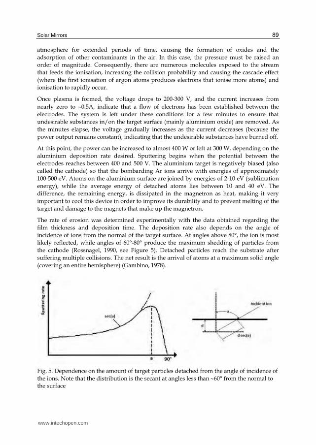
The rate of erosion was determined experimentally with the data obtained regarding the film thickness and deposition time. The deposition rate also depends on the angle of incidence of ions from the normal of the target surface. At angles above 80°, the ion is most likely reflected, while angles of 60°-80° produce the maximum shedding of particles from the cathode (Rossnagel, 1990, see Figure 5). Detached particles reach the substrate after suffering multiple collisions. The net result is the arrival of atoms at a maximum solid angle (covering an entire hemisphere) (Gambino, 1978).
Fig. 5. Dependence on the amount of target particles detached from the angle of incidence of the ions. Note that the distribution is the secant at angles less than 60° from the normal to the surface
www.intechopen.com

Solar Power
90
Tables 2 and 3 show typical parameters for the operation conditions employed during the deposition of aluminium and quartz. When the aluminium foil has reached the desired thickness, quartz deposition is initiated. As previously explained, when dielectric quartz sputtering is required, it is obtained via a radiofrequency power supply rather than direct current.
System Pressure
[Torr]
Power supply [W]
Current [A]
Voltage [V]
Run time [h:m]
Effective time [min]
7.4x10⁻⁴ 160 0.6 – 0.7 269 – 280 11:17 0 7.8x10⁻⁴ 200 0.72 274- 11:22 0 7.5x10⁻⁴ 250 0.86 287 11:27 0 7.3x10⁻⁴ 250 0.46 528 11:30 0* 7.2x10-4 300 0.55 539 11:32 2 7.2x10⁻⁴ 350 0.64 545 11:34 4 7.4x10⁻⁴ 350 0.65 535 11:48 18
(Pmin= 4.4x10⁻⁵ Torr; Film thickness 1000 Å) *Note: at this time the mirror is placed in front of the magnetron.
Table 2. Typical run for the deposition of aluminium using direct current for sputtering
System Pressure
[Torr]
Power [W]
Polarisation of electrodes
[V]
Runtime [h:m]
Effective time [m:s]
Selected Reflected Supplied 7.8x10⁻³ 3 2 5 0 12:21 0 2.2x10⁻³ 100 2 102 -12 12:23 2:20 2.1x10⁻³ 200 2 202 -23 12:25 4:40 2.0x10⁻³ 300 2 302 -31 12:27 6:40 2.1x10⁻³ 400 2 402 -39 12:29 8:40 2.3x10⁻³ 500 3 503 -47 12:31 10:40 2.5x10⁻³ 600 3 603 -54 12:33 12:40 2.2x10⁻³ 700 3 703 -59 12:35 14:40 2.5x10⁻³ 800 3 803 -59 12:37 16:40 2.4x10⁻³ 800 3 803 -59 12:39 18:00* 2.1x10-3 790 2 792 -64 12:49 28:00 2.6x10⁻³ 790 2 792 -65 12:59 38:00 2.7x10⁻³ 790 2 792 -64 13:19 58:00 2.1x10⁻³ 790 3 793 -63 13:29 68:00 3.2x10⁻³ 790 3 793 -63 13:39 78:00
(Pmin= 1.9x10⁻⁵ Torr; atmosphere with 25% O2; Film thickness 5000 Å) *Note: at this time the mirror is placed in front of the magnetron.
Table 3. Typical run for the deposition of quartz with radiofrequency ion erosion
www.intechopen.com

Solar Mirrors
91
The argon plasma does not guarantee quartz deposition; therefore, deposition depends on the power required to ensure an acceptable evaporation rate, which can also cause Si-O bonds to break. This decomposition of some molecules of quartz (SiO2) was evident by the yellowing appearance of the substrate; this yellowing is typical of films of silicon monoxide used in mirrors. Because this undesirable colour lowers the reflectance of the mirrors, we introduced a percentage of oxygen as a working gas to ensure that the SiO molecules reacted and this yellow colour was eliminated (by oxygen’s action via reactive evaporation over the quartz film (Hass, 1982).
However, the presence of oxygen decreases the ion erosion rate. This is because, in order for this gas (oxygen) to be reactive and to adsorb and coat the quartz target surface to cause the formation of SiO2 molecules, one must spend an ion to remove the oxygen out of the way that stands. The associated kinetics was studied by Jones et al. (1968). High concentrations of oxygen (at 50% -35%) slowed the process and caused plasma instability manifested by small oscillations in pressure. This caused the impedance of the system to vary continuously, causing the reflected power to increase.
The optimum oxygen levels were determined to be from 15% to 30%. The magnetron was lit at pressures of 6 to 8x10⁻³ Torr. The working pressure was 2 to 2.5x10⁻³ Torr and the deposition time was 1 hour at a power from 800 to 850 W.
During sputtering of both substances, the glass substrate is kept in constant motion with the help of an engine adapted for this purpose (in order to provide coverage for a larger area). This allows the uniform deposition of 60x30 cm mirrors. Mirror size was determined by the space limitations imposed by the evaporation chamber.
It is important to note that the erosion rate depends on the RF-biased electrodes with respect to the plasma (Figure 6). The larger the polarisation, the more ions it will attract and, along the way, the more kinetic energy it will acquire. Thus, during the experimental polarisation of -65 V, the quartz deposition rate was almost double that obtained at -40 V.
The origin of this polarisation arises from the high mobility of electrons compared to ions. The high flow of electrons to the electrodes causes the plasma to acquire a positive potential because of the excess positive ions.
In our case, the cathode was connected to the RF source through a capacitor in series with the coupling impedance, and the area of the substrate was greater than the cathode.
Fig. 6. An approximation of voltage versus time based on the potential of the plasma during radiofrequency sputtering, V is the potential of the substrate
www.intechopen.com

Solar Power
92
Thus, the average current of ions and electrons reaching the electrodes is the same condition that is met if the electrodes were to acquire a negative bias, thereby slowing down the electrons and speeding up the ions. The extent of polarisation depends on the system pressure. If the pressure increases to maintain constant power, the polarisation decreases. This is partly due to the drop in voltage caused by the increase of neutral particles that reduce the impedance of the plasma.
3.3 Formation mechanism of the films
In magnetron sputtering, the substrate is far away from the bulk of the plasma, which is confined near the target surface by the magnetic field of the magnetron. It, therefore, suffers little bombardment by high energy electrons or plasma ions. In addition, the presence of the magnetic field enables the use of lower pressures because the particles are confined to a small region due to the collisions between them. To maintain low pressure, the mean free path of the atoms sputtered over the substrate increases with very little loss of kinetic energy (15 to 25 eV for light metals and up to 50 eV for heavy metals).
Several atomic processes determine the growth of a film in its initial phase, including condensation, adsorption, surface diffusion, diffusion into the film and nucleation (Lüth, 1993) (Figure 7).
Fig. 7. Representation of the processes involved in film growth on a solid surface. Substrate atoms are open circles
Film depositions occur via the condensation of atoms incident to the glass substrate. The condensation of a new material is given by the amount of particles arriving/cm2 per second. It can be divided into three stages. In the first stage, the bombarding atoms transfer kinetic energy to the atoms of the substrate network and are incorporated with weak bonds (adsorption). In the second phase, they spread over the surface, exchanging energy with the structural network of the substrate and some other species that are adsorbed, until they obtain favourable locations or low energy and effectively become defects on the surface of the substrate. At these sites, more atoms begin to accumulate, forming small islands. This phenomenon is called nucleation. The nuclei grow and coalesce to become a continuous layer of the substance on the substrate. The density and size of the islands have great influence on the interface with the substrate and, thus, the film adhesion. The ion bombardment and the high kinetic energy of the atoms arriving favours the creation of zones of nucleation, resulting in more areas of growth and less crowding in one place. This effect also decreases the amount of micro holes (Mattox, 1978), such that the interface of the film is described as more continuous or fine-grain. However, if nucleation areas are few, the
www.intechopen.com
Solar Mirrors
93
interface will have a "coarse type” structure. Once the film is continuous, growth happens on the surface as the result of the diffusion of newly arriving atoms. Finally, in the third stage, the incorporated atoms are rearranged by diffusion processes. Substrate and film atoms are exchanged, and the interface between the two substances becomes gradual. This enhances the film adhesion and reduces tension in the solid network caused by the creation of the interface between the two substances. In other words, the atoms of both materials are rearranged and settle at energetically favourable sites.
This is true for aluminium, but not for quartz (SiO2), where the surface diffusion of atoms is almost zero. The phenomenon is manifested in the variation of film thicknesses along the mirror as a function of the target position (direction of arrival). Another consequence is the appearance of holes or trenches in the film (up to the microscopic level), which are caused by shading phenomena due to oblique incidence angles. This leads to the production of less dense and porous films with low refractive indexes.
Films with grain structures occur in systems with low substrate temperatures and relatively high pressures and where the mean free paths are short. This results in oblique incidence angles that favour growth atop the defects on the substrate surface, which in turn induces a shadow effect that accentuates the lack of uniformity throughout the film.
These defects are reduced when the polarization of the electrodes is increased, resulting in an increase in particle bombardment on the target surface and deposit on the substrate, so that there is a re-sputtering making it possible most particles are deposited on the substrate and fill the gaps that still remain (Müller, 1987).
The films have different structures depending on which of the three processes were more important during the film formation. This importance is given by the ratio T/Tm, where T is the substrate temperature and Tm is the melting point of the sputtered material in degrees absolute (Thornton, 1974).
4. Accelerated ageing tests
This chapter describes accelerated environment ageing tests for Al-SiyOx first surface solar mirrors, including humidity, thermal cycling, temperature, salt water immersion, sulphur dioxide, and abrasion. Experimental procedures are described in detail. Specular reflectance measurements of tested mirror samples are used as the basis for an inspection technique for assessing performance degradation. The main goals of these tests were to determine the protection provided by a SiyOx layer over an Al reflecting film and to assess the environmental stability of such mirrors. The experimental results show that SiyOx layers play an important role in protecting the mirrors, enabling them to be quite stable under the test conditions employed.
Two approaches can be applied to evaluate environment ageing tests and to study the degradation of solar mirrors: 1) outdoor natural weathering exposure and 2) accelerated environment ageing tests. Accelerated environment ageing tests are very often employed to evaluate and examine the performance of solar mirrors by means of simulated artificial environment conditions. In general, commercially available reflector materials are exposed to accelerated ageing in a climatic test chamber. In some cases, the experimental tests will substitute devices when the chamber is not available.
www.intechopen.com

Solar Power
94
4.1 Preparation and selection of mirrors for tests
All Al-SiyOx first surface mirrors were manufactured using a high Al deposition rate and a low SiyOx deposition rate (Jiefeng et al., 1992). Their dimensions were 100 x 40 x 3 mm. The main difference among these samples was the thickness of the SiyOx layer over the Al reflecting film, which varied from 1500 Å to 2800 Å. In each test, samples with different SiyOx layer thicknesses were included. In order to determine the influence of tin from the glass surface on mirror properties, some sample films were deposited over the tin-poor surface of float glass substrates, while others were deposited over the tin-rich surface.
Humidity tests were used to examine three other kinds of mirror samples (in addition to Al-SiyOx first surface mirrors) obtained from different manufacturers, as follows: silver second surface mirrors with low iron glass and with plastic film (3M® Company) as substrates, and polished Al-sheet first surface mirrors. These three kinds of mirrors provided a comparison with the Al-SiyOx first surface mirrors.
4.2 Experimental program
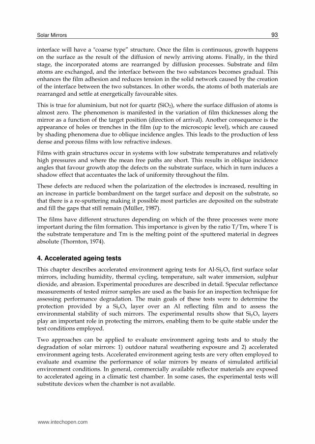
a) Humidity Tests: The exposure box used in these tests is illustrated in Figure 8. The box was made of stainless steel and heat-insulating materials. Its inner dimensions were as follows: 100 cm long, 100 cm wide and 100 cm high. The test chamber was connected to a steam generator, a Samsung HU-820A Ultrasonic Humidifier, by a tube. The relative humidity (RH) in the chamber was measured with a Vaisala Humidity and Temperature Indicator HMI31 and was controlled and adjusted by changing the vapour flow produced by the steam generator. To prevent water vapour loss, the box was sealed with a rubber gasket. The electric heater and cryogenic refrigerator provided higher or lower temperature conditions inside the box. Thermocouples were used to monitor the inner temperature of the chamber during the experiment. A fan was used to maintain a constant uniform temperature and humidity inside the chamber.
The humidity tests were performed using two exposure conditions:
1. Room Temperature, 100% RH 2. 50°C, ~ 60% RH.
Clean mirror samples were deployed on a sample-frame, which was then placed at the centre of the bottom of the chamber. When the steam humidifier began to work, the cover of the chamber was closed. At this point, water vapour began to flow. The desired rate was obtained by adjustments. When temperatures that were higher or lower than room temperature were needed, the heater or the cryogenic refrigerator was used. Thus, various combinations of humidity and temperature were obtained. During the tests, reflectance of the samples was measured periodically.
b) Thermal Cycling: Under outdoor applications, solar mirrors were subjected to high and low temperature conditions. Tests were conducted to examine the bonding between films and their glass substrates under the above environmental thermal cycling (Figure 8).
Firstly, mirror samples were placed into an oven at 50°C with an ambient humidity for 1 h, then removed from the oven, cooled down to room temperature and maintained at that temperature for another 1 h. Then, the samples were dipped into a tank filled with liquid nitrogen for 20 min. Then they were removed from the liquid nitrogen, were allowed to reach
www.intechopen.com
Solar Mirrors
95
room temperature again and were maintained at that temperature for 1 h. The above process was repeated several times. The appearance of the mirrors was recorded after every cycle.
Fig. 8. Box for Humidity Test and Temperature Control Unit
c) Temperature Test: In general, temperature is very important with regard to mirror degradation because of its obvious effects on degradation rates. High temperature can cause mirror performance to degrade rapidly. According to the recommendation contained in Masterson et al. (1983), high temperature exposures must not exceed 80°C. The objective of temperature tests was to examine the thermal stability and performance degradation of first surface mirrors under high temperature conditions.
The specimens were heated by inserting them into a laboratory furnace kept at 70°C under ambient laboratory humidity. All samples were maintained at the same uniform temperature. After every successive 24 h, the appearance and reflectance of the mirrors were evaluated.
d) Salt Water Immersion: For this test, a solution with 5% (w/w) concentration of NaCl (instead of salt mist) was used. The immersion of the mirrors was conducted at temperatures ranging from 13 to 16°C in our study. In order to monitor the corrosion, appearance and reflectance of the tested mirrors, they were examined at intervals of 24 h after immersion.
e) Exposure to Moist Sulphur Dioxide: In order to simulate industrial atmospheric corrosion, sulphur dioxide (SO2) was chosen as a pollutant. Samples were placed in a glass desiccator having a volume of 10 dm3 and containing 50 mL of water. SO2 was produced by the chemical reaction 2.
Na態SO戴 + H態SO替 → Na態SO替 + H態O + SO態 (2)
By introducing 5 g of Na2SO3 into the glass chamber, then adding sulphuric acid slowly and intermittently, SO2 was produced (Dennis & McGee, 1980). It was introduced into the chamber through a rubber hose. In order to detect SO2 in the chamber, a piece of wetted pH value paper was placed in the same position of the exposed samples. When the pH paper showed a null (0) pH value, introduction of SO2 was stopped and the chamber sealed. The appearance and optical properties of the mirrors were examined periodically. The chamber was refilled with SO2 after each inspection.
f) Abrasion Test: Under outdoor environments, solar mirrors will accumulate dust and wind-borne particles; therefore, repeated cleaning of their surfaces is needed during the service period. These likely damage the specularity and lower the efficiency of a concentrating
www.intechopen.com

Solar Power
96
mirror. Thus, abrasion-resistance for first surface mirrors is clearly an important avenue for advancement.
A simple abrasion test using a clean, soft cloth was performed under dry and wet conditions separately. The procedure for the abrasion test was as follows: 1) the surfaces of the test mirrors were wiped using a dry, clean and soft cloth; 2) wet abrasion tests were performed using a clean, soft cloth soaked with an aqueous solution of a common detergent. Every 10 wipes, the surfaces of the tested mirrors were observed in order to determine whether any film damage occurred. After such tests, mirror surfaces were cleaned and reflectance measurements were conducted.
4.3 Results and analyses
a) Humidity Tests: were performed in triplicate. Two tests were performed at room temperature and 100% RH, and the third was conducted at 50°C and ~ 60% RH. The experimental results are listed in Tables 4, 5 and 6.
Spots appeared early in the humidity tests and remained unchanged in size thereafter. It is assumed that these consisted of alumina formed as a result of pinhole defects in the SiyOx film, where the Al film would have been exposed to water vapour and, therefore, oxidized during the test.
As a result, formation of Al2O3-H2O would block and seal the original defect, preventing oxidation of the Al film around the holes and thereby limiting the size of the spots. Sample 4-8-2 showed a severe drop in reflectance. The reason was that the SiyOx layer was too thin to protect the Al reflecting film.
Additional mirrors with thicker films were manufactured. These were subjected to two humidity tests. Firstly, the samples listed in Table 3 were tested at room temperature and 100% RH for three and four weeks. After that, they were exposed to 50 °C and ~ 60% RH for two weeks. The experimental parameters and results are summarised in Tables 4, 5 and 6.
Sample Thickness Reflectance ()* Comments
Al film SiOx
film Unexposed Exposed[weeks]
[Å] [Å] 1 2 3 4 4-8-2 1517 748 0.786 0.776 0.767 0.763 0.767 Small holes 4-27-2 2000 2000 0.804 0.817 0.814 0.815 0.809 4-20-1 2000 2200 0.776 0.790 0.785 0.785 0.785 Very small holes 3-11-2 1340 2230 0.813 0.825 0.822 0.822 0.818 Very small holes 5-4-3 2000 2500 0.829 0.839 0.839 0.841 0.835 4-29-3 4000 2500 0.827 0.837 0.833 0.833 0.831 4-1-1 1500 2520 0.807 0.811 0.809 0.808 0.808 Very small holes 4-27-9 2000 2000 0.786 0.776 0.767 0.763 0.767 Small holes
*Reflectance measurements of samples were performed using SSR. Slide glass sheet. Corning 7059 Sheet glass.
Table 4. Reflectance of mirrors exposed at room temperature and 100% RH environment for up to four weeks
www.intechopen.com

Solar Mirrors
97
Tables 5 and 6 show superior experimental results compared to Table 4. No obvious degradation of performance occurred except in the case of the 3M silvered-tape sample, which showed severe edge corrosion after exposure to room temperature and 100% RH for 3 days. Water vapour permeated between the silver reflecting layer and covering (plastic film) causing degradation of the silver layer reflectance.
Sample Thickness Reflectance ()* Comments
Al film
SiOx
filmUnexpose
dExposed[weeks]
[Å] [Å] 1 2 3 10-7-1 1257 2850 0.888 0.887 0.887 0.887 10-1-1 980 1557 0.852 0.853 0.852 0.853 9-29-2 1413 1552 0.850 0.850 0.851 0.851 9-24-1 1454 2600 0.879 0.880 0.879 0.879 9-18-1 1225 2534 0.886 0.887 0.886 0.887 9-14-2 1247 2361 0.884 0.884 0.882 0.884 9-8-2* 1012 2053 0.868 0.868 0.866 0.868 7-16-2 1000 2200 0.875 0.876 0.873 0.875 7-8-1 1092 2000 0.871 0.873 0.870 0.873
Al sheet 0.896 0.896 0.893 0.894 Ag mirror 0.920 0.919 0.920 0.920
3M® silvered-tape 0.963 0.962 -- -- Heavy edge corrosion
*Films were deposited on the tin-rich surface of float glass substrate
Table 5. Reflectance of mirrors exposed to room temperature and 100% RH environment for up to three weeks
Sample Thickness Reflectance ()
Al film SiOx film Unexposed Exposed [weeks]
[Å] [Å] 1 2 10-7-1 1257 2850 0.887 0.888 0.887 10-1-1 980 1557 0.853 0.853 0.853 9-29-2 1413 1552 0.851 0.851 0.850 9-24-1 1454 2600 0.879 0.879 0.879 9-18-1 1225 2534 0.887 0.887 0.886 9-14-2 1247 2361 0.884 0.884 0.884 9-8-2 1012 2053 0.868 0.867 0.867 7-16-2 1000 2200 0.875 0.874 0.867 7-8-1 1092 2000 0.973 0.871 0.872
Al sheet 0.894 0.893 0.893 Ag mirror 0.920 0.918 0.918
Table 6. Reflectance of mirrors exposed to 50 °C and 60% RH environment for up to two weeks
www.intechopen.com

Solar Power
98
b) Thermal cycling: After every thermal cycle, the surfaces of tested mirrors were carefully checked to determine if any damage, crack or exfoliation of the films took place. When the tests were finished, the surfaces of the samples were cleaned and reflectance measurements were carried out. Five cycling times were performed and the results are summarised in Table 7.
During thermal cycling, the experimental conditions were very harsh. Two samples cracked, but the properties of the films in all five samples remained intact. When liquid nitrogen is used as the low temperature environment, the ageing test can be accelerated further and the test period reduced. However, if experimental conditions permit, a low temperature environment of dry ice plus alcohol is preferable.
Sample Thickness Reflectance () Comments Al film SiOx film Previous After 5 [Å] [Å] cycles
10-7-3 1257 2850 0.884 0.88 9-24-2 1454 2600 0.877 0.874 9-18-2 1225 2534 0.885 -- Glass was cracked 8-26-3 1000 2300 0.886 0.883 7-16-1 1000 2200 0.878 0.878 Glass was cracked
Table 7. Results of thermal cycling test
c) Temperature test: Four pieces of mirror samples were heated in the oven at 70°C for 72 h. At 24 h intervals, the samples were removed from the oven, and the appearance and reflectance were checked and measured. The samples were then returned to the oven for further treatment. No detectable change in the samples was observed after thermal treatment for 72 h. Table 8 shows the results of the temperature test.
Sample Thickness Reflectance () Al film SiOx film Initial Heated [Å] [Å] 24 h 48 h 72 h
9-24-3* 1413 1552 0.846 0.847 0.848 0.847 9-22-3* 1208 2500 0.868 0.869 0.867 0.866 9-14-1 1247 2361 0.885 0.886 0.885 0.885 7-1-2 1000 2000 0.865 0.864 0.863 0.863
Table 8. Results of temperature test of mirrors in air at 70 °C
d) Exposure to moist sulphur dioxide: was conducted for 48 h. At regular intervals, the samples were removed from the test chamber, and their appearance and reflectance were measured. The samples were then returned to the chamber for further exposure. The experimental results are given in Table 9. After 24 h exposure, sample 9-24-3 first showed very obvious corrosion (transparent small holes were present). Its reflectance decreased as well, even though a thicker SiyOx layer (2600 Å) was deposited on its surface. This may be exceptional and related to the preparation processes of the batch containing sample 9-24-3.
www.intechopen.com

Solar Mirrors
99
Sample Thickness Film Reflectance ()
Al SiOx Initial Exposed [Å] [Å] 1 h 3 h 6 h 12 h 24 h 48 h
9-29-1 1413 1552 0.852 0.853 0.853 0.852 0.852 0.840 0.830 9-24-3 1453 2600 0.874 0.873 0.873 0.874 0.874 0.872 0.864 9-18-3 1225 2534 0.881 0.881 0.880 0.881 0.880 0.881 0.881 8-20-1 1167 2105 0.881 0.880 0.880 0.880 0.879 0.880 0.879 7-8-2 1092 2000 0.872 0.873 0.873 0.872 0.872 0.873 0.872
Table 9. Results of exposure to moist sulphur dioxide
e) Salt water immersion: At every 24 h interval, the samples were withdrawn from the salt solution, rinsed with distilled water and dried. Then the appearance was checked and the reflectance measured. Table 10 summarises the results of the salt water immersion test. After 72 h immersion, there was no drop in the reflectance nor change in the appearance of three of the samples. However, noticeable corrosion occurred at a local area of sample 10-1-3 after 24 h immersion (Figure 9).
Sample Thickness Reflectance ()* Comments Al film SiOx film Initial Immersed [Å] [Å] 24 h 48 h 72 h
10-7-3 1257 2850 0.884 0.884 0.884 0.884 10-1-3 980 1557 0.845 0.845 0.847 -- 9-14-3 1247 2361 0.879 0.878 0.881 0.880 Local corrosion 7-16-3 1000 2200 0.868 0.868 0.869 0.868
Table 10. Results of salt water immersion
Fig. 9. Photograph of Sample 10-1-3 after 24 h immersion showing corrosion
On the corroded area, the Al reflecting film disappeared. However, no corrosion was observed in the rest of this sample, including its edges. Therefore, it was determined that the local corrosion of sample 10-1-3 resulted from defects in the SiyOx layer.
www.intechopen.com
Solar Power
100
f) Abrasion test: On each sample surface, 200 wiping strokes of dry or wet abrasion were conducted. No obvious changes in the appearance or the reflectance of tested samples were observed.
5. Conclusions
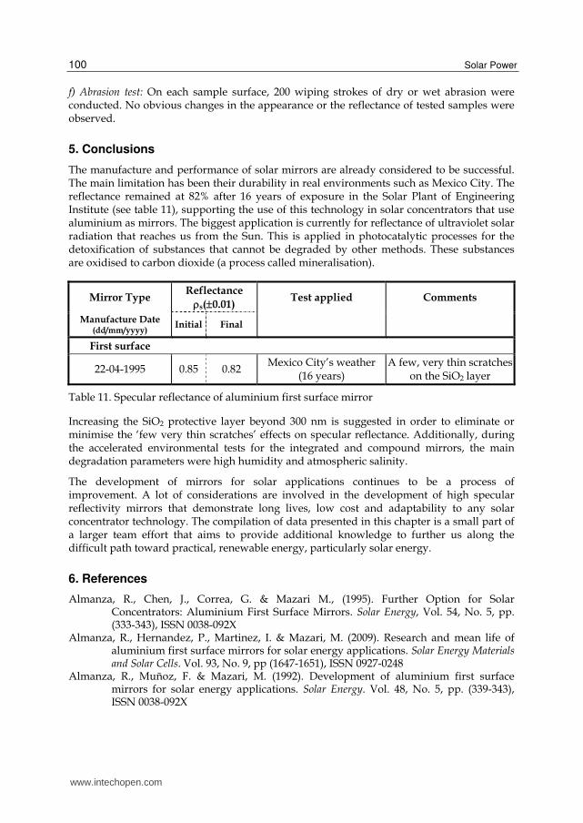
The manufacture and performance of solar mirrors are already considered to be successful. The main limitation has been their durability in real environments such as Mexico City. The reflectance remained at 82% after 16 years of exposure in the Solar Plant of Engineering Institute (see table 11), supporting the use of this technology in solar concentrators that use aluminium as mirrors. The biggest application is currently for reflectance of ultraviolet solar radiation that reaches us from the Sun. This is applied in photocatalytic processes for the detoxification of substances that cannot be degraded by other methods. These substances are oxidised to carbon dioxide (a process called mineralisation).
Mirror Type Reflectance
s(0.01) Test applied Comments
Manufacture Date (dd/mm/yyyy)
Initial Final
First surface
22-04-1995 0.85 0.82 Mexico City’s weather (16 years)
A few, very thin scratches on the SiO2 layer
Table 11. Specular reflectance of aluminium first surface mirror
Increasing the SiO2 protective layer beyond 300 nm is suggested in order to eliminate or minimise the ‘few very thin scratches’ effects on specular reflectance. Additionally, during the accelerated environmental tests for the integrated and compound mirrors, the main degradation parameters were high humidity and atmospheric salinity.
The development of mirrors for solar applications continues to be a process of improvement. A lot of considerations are involved in the development of high specular reflectivity mirrors that demonstrate long lives, low cost and adaptability to any solar concentrator technology. The compilation of data presented in this chapter is a small part of a larger team effort that aims to provide additional knowledge to further us along the difficult path toward practical, renewable energy, particularly solar energy.
6. References
Almanza, R., Chen, J., Correa, G. & Mazari M., (1995). Further Option for Solar Concentrators: Aluminium First Surface Mirrors. Solar Energy, Vol. 54, No. 5, pp. (333-343), ISSN 0038-092X
Almanza, R., Hernandez, P., Martinez, I. & Mazari, M. (2009). Research and mean life of aluminium first surface mirrors for solar energy applications. Solar Energy Materials and Solar Cells. Vol. 93, No. 9, pp (1647-1651), ISSN 0927-0248
Almanza, R., Muñoz, F. & Mazari, M. (1992). Development of aluminium first surface mirrors for solar energy applications. Solar Energy. Vol. 48, No. 5, pp. (339-343), ISSN 0038-092X
www.intechopen.com

Solar Mirrors
101
Ashley, C., Reed, S. & Mahoney, A. (1988). Planarization of metal substrates for solar mirrors. Proceedings 121 of the Material Research Society Symposium, USA, ISSN: 0272-9172
Blake, D., Link, H. & Eber, K. (1992). Solar photocatalytic detoxification of water, In: Advances in solar energy, ed. K.W.Boer, American Solar Energy Society, ISSN 0731-8618
Brawn, R. (1970). Thin Film Substrates, In: Handbook of Thin Film Technology. McGraw Hill, USA, ISBN 978-0070397422
Brogren, M., Helgesson, A., Karlsson, B., Nilsson, J. & Roos, A. (2004). Optical properties, durability, and system aspects of a new aluminium-polymer-laminated steel reflector for solar concentrators. Solar Energy Materials & Solar Cells. Vol. 82, No. 3, pp. (387-412), ISSN 0927-0248
Correa, G., Almanza, R., Martínez, I. & Mazari, M. (1998). Use of linear Magnetrons for the fabrication of Aluminium first Surface Solar Mirrors. Solar Energy Materials and Solar Cells, Vol. 52, No. 3-4, pp. (231-238), ISSN 0927-0248
Dennis, W. & McGee, J. (1980). Silicone resins for protection of first surface reflectors. Solar Energy Materials, Vol. 3, No. 1-2, pp. (285-300), ISSN 0165-1633
Dennis, W. (1979). Protective coatings for front surface reflectors. Phase I. Report DOE/ET/21070-TI, USA
Drummeter, L. & Haas, G. (1967) Solar absorptance and thermal emittance of evaporated coatings, In: Physics of thin films, Volume 4, Haas, G. & Thun, R. p. (4), Academic press, New York, ASIN B004YWF47Y
Fend, T., Hoffschmidt, B., Jorgensen, G., Küster, H., Küster, H., Krüger, D., Pitz-Paal, R., Rietbruck, P. & Riffelmann, K. (2003). Comparative assessment of solar concentrator materials. Solar Energy, Vol. 74, pp. (149-155), ISSN 0038-092X
Fend, T., Jorgensen, G. & Küster, H. (2000). Applicability of highly reflective aluminium coil for solar concentrators. Solar Energy, Vol. 68, No. 4, pp. (361-370), ISSN 0038-092X
Gambino, R. & Cuomo, J. (1978). Selective resputtering-induced anisotropy in amorphous films. Journal of Vacuum Science and Technology, Vol. 15, No. 2, p. (6), ISSN 0734-2101
Glang, R. & Gregor, L. (1970). Generation of patterns in thin films, In: Handbook of thin film technology, Maissel, L. & Glang, R., McGraw Hill, ISBN 978-0070397422
Glang, R. (1970). Vacuum evaporation, In: Handbook of thin film technology, Maissel, L. & Glang, R., McGraw Hill, ISBN 978-0070397422
Haas, G., Heaney, J. & Hunter, W. (1982). Reflectance and preparation of front surface mirrors for use at various angles of incidence from the ultraviolet to the far infrarred, In: Physics of thin films, Volume 12, Haas, G., Francombe, M. & Vossen, J., p. (12), Academic Press, ISBN 9780125330121
Hass, G. (1982). Reflectance and preparation of front-surface mirrors for use at various angles of incidence from the ultraviolet to the far infrared. Journal of the Optical Society of America, Vol. 72, No. 1, pp. (27-39), ISSN 0030-3941
Hernandez, T., Moroño, A. & Hodgson, E. (2003). Radiation enhanced degradation of aluminium mirrors for remote handling and diagnostics applications. Effect of humidity. Fusion Engineering and Design. Vol. 69, pp. (177-182), ISSN 0920-3796
Jiefeng, C., Almanza, R., Mazari, M. & Correa, G. (1993). Accelerated Ageing Test For Al-SiyOx First Surface Solar Mirrors. Series del Instituto de Ingeniería en Lenguas Extranjeras E-61, pp. (1-39). Instituto de Ingeniería, UNAM, México.
Jones, R., Winters, H. & Maissel, U. (1968). Effect of oxygen on the rf-sputtering rate of SiO2. Journal of Vacuum Science and Technology, Vol. 5, No. 3, p. (4), ISSN 0734-2101
www.intechopen.com
Solar Power
102
Jorgensen, G., Williams, T. & Wendelin, T. (1994). Advanced reflector materials for solar concentrators. Proceedings of the 7th International Symposium on Solar Thermal Concentrating Technologies, Russia
Kearney, D. & Price, H. (2005). Recent advances in parabolic trough solar power plant technology, In: Advances in Solar Energy. An annual review of research and development. American Solar Energy Society, Earthscan, pp. (175-179), ISSN 0731-8618
Kennedy, C. & Jorgensen, G. (1994). State of the art low-cost solar reflector materials. NREL/TP-471-7022, DE95000260, USA, pp. (1-15)
Kennedy, C., Smilgys, R., Kirkpatrick, D. & Ross J. (1996). Optical performance and durability of solar reflectors protected by an alumina coating. National Renewable Energy Laboratory. NREL/TP-471-21413, No. SE612033, USA
Kennedy, C., Terwill, K., & Jorgensen, G. (2005). Analysis of accelerated exposure testing of thin glass mirror matrix. Proceedings of the ISES World Congress, USA, pp. (1-7)
Lüth, H. (2001). Solid Surfaces, Interfaces and Thin Films. (4th edition), Springer, Berlin, ISBN 978-3540423317
Maissel, L. & Glang, R. (1970). Handbook of Thin Film Technology. McGraw-Hill, New York, USA, ISBN 978-0070397422
Martin, P., Affinito, J., Gross, M., & Bennet, W. (1994). Coatings for large area low-cost solar concentrator and reflectors. Proceedings of SPIE, USA
Martinez, I., Almanza, R., Mazari, M. & Correa, G. (2000). Parabolic trough reflector manufactured with aluminium first surface mirror thermally sagged. Solar Energy Materials and Solar Cells, Vol.64, No. 1, pp. (85-96), ISSN 0927-0248
Masterson, K., Czanderna, A., Blea, J., Goggin, R., Gutierrez, M., Jorgensen, G., McFadden & J. (1983). Matrix Approach to Testing Mirrors, Part 2. SERI/TR-255-1627 DE 83 011996
Mattox, D. (1978). Thin film adhesion and adhesive failure - a perspective, In: Adhesion Measurement of Thin Films, Thick Films, and Bulk Coatings, Mittal, K.L., ASTM STP640-EB, American Society for Testing Materials, p. (9), USA, ISBN 978-0803155466
Morales, A. & Ajona, J. (1996). Durability and performance test of sol-gel front surface silver mirrors. Proceeding of the 8th International Symposium on Solar Thermal Concentrating Technologies, Germany, pp. (463-476)
Morales, A. & Ajona, J. (1999). Durability, performance and scalability of sol-gel front surface mirrors and selective absorbers. Journal of Physics IV, France, pp. (513-518)
Morales, A. & Durán, A. (1997). Sol-Gel Protection of Front Surface Silver and Aluminium Mirrors. Journal of Sol-Gel Science & Technology, Vol. 8, No. 1-3, pp. (451-457), ISSN 0928-0707
Pulker, H. (1999). Coatings on Glass. (2nd edition), Elsevier Science, The Netherlands, ISBN 978-0444501035,
Rossnagel, S., Cuomo, J. & Westwood, W. (1991). Handbook of plasma processing technology, fundamentals, etching, deposition and surface interactions. Noyes publications, New Jersey, USA, ISBN 978-0815512202
Schissel, P., Jorgensen, G., Kennedy, C. & Goggin, R. (1994). Silvered-PMMA reflectors. Solar Energy Materials & Solar Cells, Vol. 33, No. 2, pp. (183-197), ISSN 0927-0248
Wasa, K. & Hayakawa, S. (1993). Handbook of sputter deposition technology, principles, technology and applications. Noyes publications, New Jersey, USA, ISBN 978-0815512806
Yang, M., Gatto, A. & Kaiser, N. (2006). Highly reflecting aluminium-protected optical coatings for the vacuum-ultraviolet spectral range. Applied Optics. Vol. 45, No. 1, pp. (178-183), ISSN 1559-128X
www.intechopen.com

Solar PowerEdited by Prof. Radu Rugescu
ISBN 978-953-51-0014-0Hard cover, 378 pagesPublisher InTechPublished online 15, February, 2012Published in print edition February, 2012
InTech EuropeUniversity Campus STeP Ri Slavka Krautzeka 83/A 51000 Rijeka, Croatia Phone: +385 (51) 770 447 Fax: +385 (51) 686 166www.intechopen.com
InTech ChinaUnit 405, Office Block, Hotel Equatorial Shanghai No.65, Yan An Road (West), Shanghai, 200040, China
Phone: +86-21-62489820 Fax: +86-21-62489821
A wide variety of detail regarding genuine and proprietary research from distinguished authors is presented,ranging from new means of evaluation of the local solar irradiance to the manufacturing technology ofphotovoltaic cells. Also included is the topic of biotechnology based on solar energy and electricity generationonboard space vehicles in an optimised manner with possible transfer to the Earth. The graphical materialsupports the presentation, transforming the reading into a pleasant and instructive labor for any interestedspecialist or student.
How to referenceIn order to correctly reference this scholarly work, feel free to copy and paste the following:
Rafael Almanza and Iván Martínez (2012). Solar Mirrors, Solar Power, Prof. Radu Rugescu (Ed.), ISBN: 978-953-51-0014-0, InTech, Available from: http://www.intechopen.com/books/solar-power/solar-mirrors

© 2012 The Author(s). Licensee IntechOpen. This is an open access articledistributed under the terms of the Creative Commons Attribution 3.0License, which permits unrestricted use, distribution, and reproduction inany medium, provided the original work is properly cited.