
Software Engineering Processes - Dalhousie University
26
Software Engineering Topic 2 Page 1 Software Engineering Processes A software engineering process is the model chosen for managing the creation of software from initial customer inception to the release of the finished product. The chosen process usually involves techniques such as • Analysis, • Design, • Coding, • Testing and • Maintenance Several different process models exist and vary mainly in the frequency, application and implementation of the above techniques, for example, different process models use different analysis techniques, other models attempt to implement the solution to a problem in one big-bang approach, while others adopt an iterative approach whereby successively larger and more complete versions of the software are built with each iteration of the process model. The Software Engineering Process - The Software Life Cycle The illustration below highlights the various phases of what is probably the oldest software development process in existence, namely the classic life-cycle paradigm, sometimes called the "waterfall model,". This paradigm implies a systematic, sequential approach (rarely achieved in practice) to software development that begins at the system level and progresses through analysis, design, coding, testing and maintenance. Modelled after the conventional engineering cycle, the life-cycle paradigm encompasses the above activities. Let’s take a look at each of these phases in turn and explain what is involved.
Transcript of Software Engineering Processes - Dalhousie University
Software Engineering Topic 2 Page 1
Software Engineering Processes A software engineering process is the model chosen for managing the creation of software from initial customer inception to the release of the finished product. The chosen process usually involves techniques such as
• Analysis, • Design, • Coding, • Testing and • Maintenance
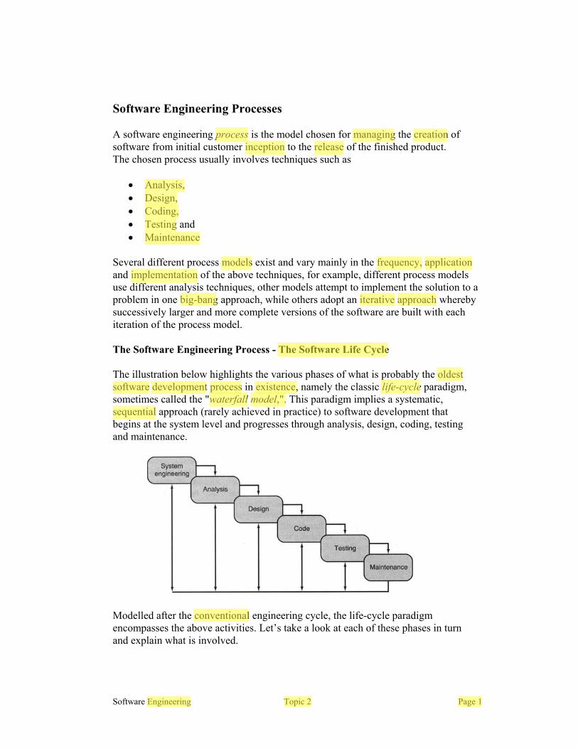
Several different process models exist and vary mainly in the frequency, application and implementation of the above techniques, for example, different process models use different analysis techniques, other models attempt to implement the solution to a problem in one big-bang approach, while others adopt an iterative approach whereby successively larger and more complete versions of the software are built with each iteration of the process model. The Software Engineering Process - The Software Life Cycle The illustration below highlights the various phases of what is probably the oldest software development process in existence, namely the classic life-cycle paradigm, sometimes called the "waterfall model,". This paradigm implies a systematic, sequential approach (rarely achieved in practice) to software development that begins at the system level and progresses through analysis, design, coding, testing and maintenance.
Modelled after the conventional engineering cycle, the life-cycle paradigm encompasses the above activities. Let’s take a look at each of these phases in turn and explain what is involved.
Paul
process
Paul
inception
Paul
managing
Paul
creation
Paul
release
Paul
Analysis,
Paul
Design,
Paul
Coding,
Paul
Testing
Paul
Maintenance
Paul
models
Paul
frequency,
Paul
application
Paul
implementation
Paul
big-
Paul
bang
Paul
iterative
Paul
approach
Paul
The Software Life Cycle
Paul
oldest
Paul
software
Paul
development
Paul
process
Paul
existence,
Paul
life-cycle
Paul
waterfall
Paul
model,".
Paul
sequential
Paul
conventional
Paul
Engineering Topic 2 Page 1

Software Engineering Topic 2 Page 2
System Engineering and Analysis. Because software almost always forms part of a much larger system, work begins by establishing requirements for all components of the system, identifying not only the role played by the software but, more importantly, its interface and interaction with the outside world. This ‘system view’ is essential when software must interface with other elements such as hardware, people, databases and computers outside of, and beyond the control of the system designer. In essence Systems engineering involves exploring some of the following issues:
1. Where does the software solution fit into the overall picture? The software being proposed may be one small cog in a very large wheel. Maybe the software is a calculating employee pay or tax, or perhaps has to co-ordinate the activities of several distributed systems controlling a production/manufacturing plant or warehouse distribution system. Until the overall picture is clear, no analysis of the software can begin.
2. What does the system do? Is it required to control or monitor some process or activity or is it simply performing analysis of data?
3. What environment will the system be placed in?
• Hostile, such as an elevator subject to vibration and dust, or friendly,
such as a cosy air-conditioned office? • Will the system be ‘real time’, ‘on-line’, ‘batch’, ‘safety critical’, ‘fault
tolerant?’ • Is it required to be mobile or does it require an electricity main outlet? • Is it embedded? • Does it require a man-machine interface? • Who or what does it interact with All of these factors could severely influence, restrict and or dictate the form of the solution.
4. What inputs and outputs are required/produced and what is the form of that data: Paper, Database, Disk file, Graphics, Network, Analogue to digital converter outputs?
In answering the above question, a list of external devices is uncovered and can be explored further, e.g. what size of paper, what resolution graphics, what format is the data accepted/displayed, what capacity of disk, what resolution of Analogue to digital converter etc.
Paul
interface
Paul
interaction
Paul
part
Paul
larger
Paul
system,
Paul
system
Paul
view’
Paul
Where
Paul
does the software solution fit into the overall picture?
Paul
overall picture
Paul
clear,
Paul
What does the system do?
Paul
Hostile,
Paul
environment
Paul
real
Paul
time’,
Paul
on-
Paul
line’,
Paul
batch’,
Paul
safety
Paul
critical’,
Paul
fault
Paul
tolerant?’
Paul
mobile
Paul
embedded?
Paul
man-
Paul
machine
Paul
Who
Paul
what
Paul
inputs
Paul
outputs
Paul
form
Paul
data:
Paul
hardware,
Paul
people,
Paul
databases
Paul
computers
Paul
interact
Paul
influence,
Paul
restrict
Paul
dictate
Paul
external
Paul
devices
Paul
employee pay
Paul
tax,
Paul
warehouse distribution

Software Engineering Topic 2 Page 3
System Engineering and Analysis…(cont.) 5. Is the system a completely new product, or is it designed to replace a
mechanical/human activity? Once this is established, the designer can assess the suitability or otherwise of a software solution to the proposed problem.
6. What user interface is needed and how is it used. For example, mouse,
keyboard, buttons on control panel, touch-screen, graphics etc?
7. Does the system impose performance requirements? For example real-time systems often specify maximum response times to events under their control, batch system do not.
8. Does the system interact with other computers and if so, what is the relationship between them in terms of what does each expect of the other?
9. What operating system and or programming languages might be required/imposed?
10. What time schedule has been proposed and how critical is it. What budget
does the customer have and is it realistic. What are the cost/benefits tradeoffs to the user in automating some manual procedure.
Of course once these questions have been answered, the developer is in a good position to assess the RISK involved in implementing the system. For example,
• Does the developer have the necessary experience and skills to implement the system or will he/she have to learn a lot of new skills?.
• Can the development be carried out with existing staff or will contractors/new staff have to be hired?
• Can the project be completed on time and within budget. Once the systems engineering and analysis phase has been completed, and a picture of the role the software plays in the overall system has been established, the analysis can now focus specifically on the software and its requirements.
Paul
new
Paul
product,
Paul
replace
Paul
human
Paul
activity?
Paul
user
Paul
interface
Paul
performance
Paul
requirements?
Paul
response
Paul
times
Paul
interact
Paul
computers
Paul
operating
Paul
system
Paul
programming
Paul
languages
Paul
time
Paul
schedule
Paul
necessary
Paul
experience
Paul
skills
Paul
existing
Paul
staff
Paul
new
Paul
staff
Paul
hired?
Paul
time
Paul
budget.
Paul
software
Paul
plays
Paul
overall
Paul
system
Paul
suitability
Paul
what does each expect of the other?
Paul
critical
Paul
contractors/
Paul
budget
Paul
realistic.
Paul
cost/benefits
Paul
RISK
Software Engineering Topic 2 Page 4
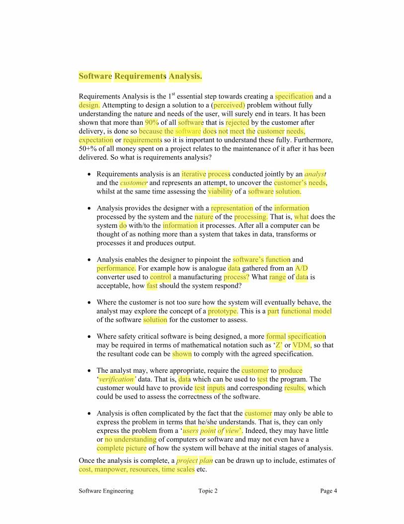
Software Requirements Analysis.
Requirements Analysis is the 1st essential step towards creating a specification and a design. Attempting to design a solution to a (perceived) problem without fully understanding the nature and needs of the user, will surely end in tears. It has been shown that more than 90% of all software that is rejected by the customer after delivery, is done so because the software does not meet the customer needs, expectation or requirements so it is important to understand these fully. Furthermore, 50+% of all money spent on a project relates to the maintenance of it after it has been delivered. So what is requirements analysis?
• Requirements analysis is an iterative process conducted jointly by an analyst and the customer and represents an attempt, to uncover the customer’s needs, whilst at the same time assessing the viability of a software solution.
• Analysis provides the designer with a representation of the information processed by the system and the nature of the processing. That is, what does the system do with/to the information it processes. After all a computer can be thought of as nothing more than a system that takes in data, transforms or processes it and produces output.
• Analysis enables the designer to pinpoint the software’s function and performance. For example how is analogue data gathered from an A/D converter used to control a manufacturing process? What range of data is acceptable, how fast should the system respond?
• Where the customer is not too sure how the system will eventually behave, the analyst may explore the concept of a prototype. This is a part functional model of the software solution for the customer to assess.
• Where safety critical software is being designed, a more formal specification may be required in terms of mathematical notation such as ‘Z’ or VDM, so that the resultant code can be shown to comply with the agreed specification.
• The analyst may, where appropriate, require the customer to produce ‘verification’ data. That is, data which can be used to test the program. The customer would have to provide test inputs and corresponding results, which could be used to assess the correctness of the software.
• Analysis is often complicated by the fact that the customer may only be able to express the problem in terms that he/she understands. That is, they can only express the problem from a ‘users point of view’. Indeed, they may have little or no understanding of computers or software and may not even have a complete picture of how the system will behave at the initial stages of analysis.
Once the analysis is complete, a project plan can be drawn up to include, estimates of cost, manpower, resources, time scales etc.
Paul
specification
Paul
design.
Paul
90%
Paul
software
Paul
rejected
Paul
software
Paul
does
Paul
not
Paul
meet
Paul
the
Paul
customer
Paul
needs,
Paul
expectation
Paul
requirements
Paul
iterative
Paul
process
Paul
analyst
Paul
customer
Paul
customer’s
Paul
needs,
Paul
viability
Paul
software
Paul
solution.
Paul
representation
Paul
information
Paul
nature
Paul
processing,
Paul
what
Paul
do
Paul
information
Paul
software’s
Paul
function
Paul
performance.
Paul
fast
Paul
range
Paul
data
Paul
data
Paul
A/D
Paul
control
Paul
process?
Paul
prototype.
Paul
part
Paul
functional
Paul
model
Paul
formal
Paul
specification
Paul
Z’
Paul
VDM,
Paul
verification’
Paul
customer
Paul
produce
Paul
data
Paul
test
Paul
test
Paul
inputs
Paul
results,
Paul
users
Paul
point
Paul
view’.
Paul
of
Paul
project
Paul
plan
Paul
Software
Paul
Requirements
Paul
Analysis.
Paul
perceived)
Paul
solution
Paul
customer
Paul
because the software
Paul
no understanding
Paul
complete
Paul
picture
Paul
cost, manpower, resources, time scales
Paul
shown
Software Engineering Topic 2 Page 5
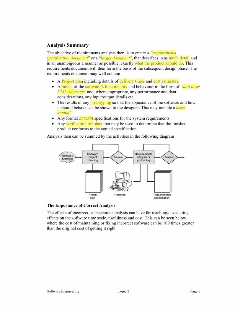
Analysis Summary The objective of requirements analysis then, is to create a “requirements specification document” or a “target document”, that describes in as much detail and in an unambiguous a manner as possible, exactly what the product should do. This requirements document will then form the basis of the subsequent design phase. The requirements document may well contain
• A Project plan including details of delivery times and cost estimates. • A model of the software’s functionality and behaviour in the form of ‘data flow/
UML diagrams’ and, where appropriate, any performance and data considerations, any input/output details etc.
• The results of any prototyping so that the appearance of the software and how it should behave can be shown to the designer. This may include a users manual.
• Any formal Z/VDM specifications for the system requirements. • Any verification test data that may be used to determine that the finished
product conforms to the agreed specification.
Analysis then can be summed by the activities in the following diagram
The Importance of Correct Analysis
The effects of incorrect or inaccurate analysis can have far reaching/devastating effects on the software time scale, usefulness and cost. This can be seen below, where the cost of maintaining or fixing incorrect software can be 100 times greater than the original cost of getting it right.
Paul
requirements
Paul
specification
Paul
document”
Paul
target
Paul
document”,
Paul
Project
Paul
plan
Paul
delivery
Paul
times
Paul
cost
Paul
estimates.
Paul
model
Paul
software’s
Paul
functionality
Paul
data
Paul
flow
Paul
diagrams’
Paul
prototyping
Paul
users
Paul
manual.
Paul
Z/VDM
Paul
verification
Paul
test
Paul
data
Paul
diagrams’
Paul
much
Paul
detail
Paul
what the product should do.

Software Engineering Topic 2 Page 6
Design and Coding Once the analysis of the system has been completed, design or development can begin. This is an attempt to translate a set of requirements and program/data models that were laid down in the “requirements document” into a well designed and engineering software solution. Design is best summarised by the following sequence of steps
• The data flow/UML diagrams that represent the system model are converted into a suitable hierarchical, modular program and data structure/architecture.
• Each program module is converted into an appropriate cohesive function subroutine or class, that is designed to perform a single well-defined task.
• Design then focuses on the implementation of each module/class. The sometimes loose and vague, perhaps English like, description of the modules role/function within the program is expanded and translated into an algorithm, which describes in detail exactly what, when and how the module/class carries out its task. The interfaces and its interaction with other modules/objects are also considered and assessed for good design (see coupling and cohesion in future lectures).
• The modules algorithm can then be translated into a flowchart, which is a step-by-step graphical representation of the actions carried out by the module expressed in terms of sequence, selection and repetition.
• The flowchart can then be translated into Pseudocode, which conveys the same information as a flowchart, but presents it a way that is more amenable to translation into program code.
• Finally, the Pseudocode for each module is translated into a chosen programming language and the various modules entered, compiled, integrated into a system ready for testing.
At each stage, the process is documented so that if changes are required in the future, the design pertinent to each stage is available for consultation and discussion. The end result of design and coding is most definitely not just the program listing. It includes the architecture data structures, algorithms, flowcharts, Pseudocode and all program source code listings, as shown below.
Paul
Design
Paul
and
Paul
Coding
Paul
translate a set of requirements and program/data models
Paul
requirements
Paul
document”
Paul
well designed and engineering software solution.
Paul
data
Paul
flow
Paul
diagrams
Paul
modular
Paul
program
Paul
structure.
Paul
implementation
Paul
algorithm,
Paul
module.
Paul
algorithm
Paul
translated
Paul
flowchart,
Paul
flowchart
Paul
translated
Paul
Pseudocode,
Paul
Pseudocode
Paul
module
Paul
chosen
Paul
programming
Paul
language
Paul
not
Paul
just
Paul
the
Paul
program
Paul
listing.
Paul
diagrams
Paul
model
Paul
architecture.
Paul
object.
Paul
architecture.
Paul
design and coding
Paul
algorithms, flowcharts, Pseudocode
Paul
program source code listings,
Software Engineering Topic 2 Page 7
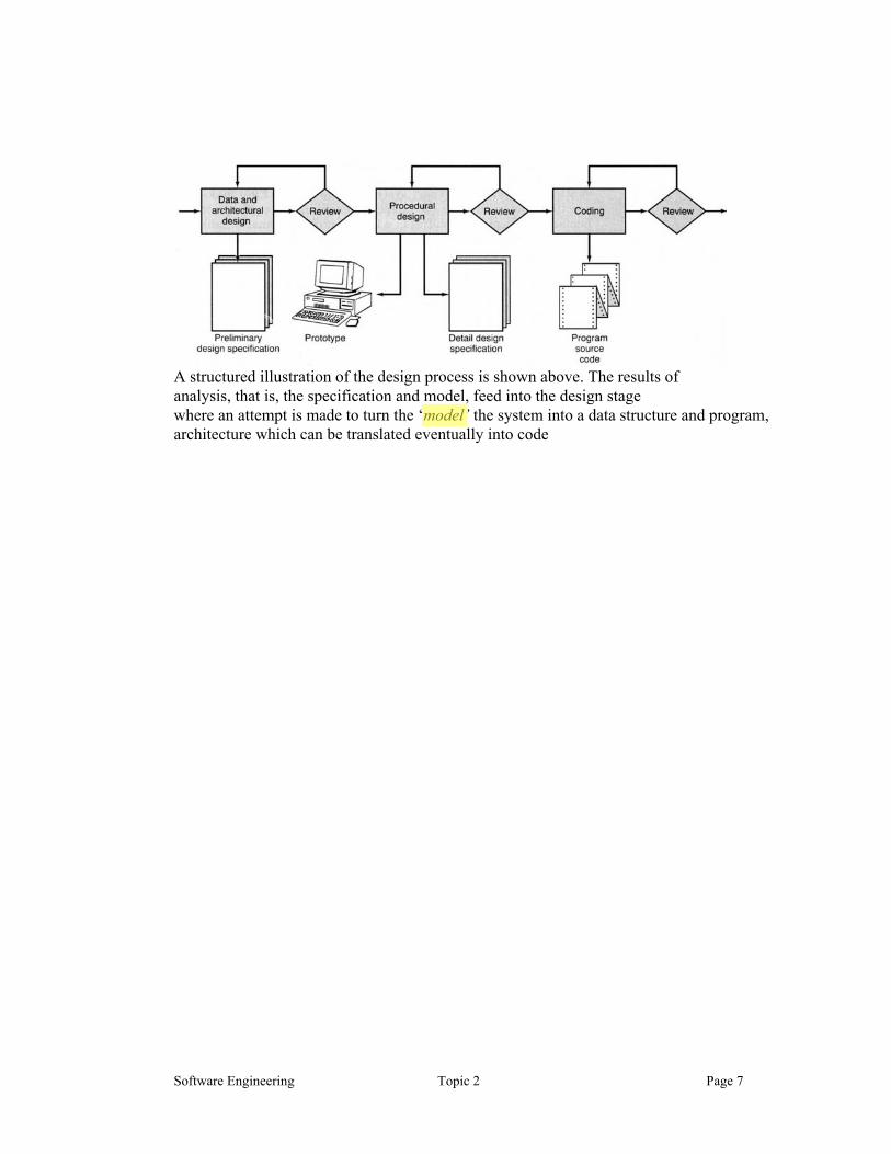
A structured illustration of the design process is shown above. The results of analysis, that is, the specification and model, feed into the design stage where an attempt is made to turn the ‘model’ the system into a data structure and program, architecture which can be translated eventually into code
Paul
model’
Software Engineering Topic 2 Page 9
Software Testing and Debugging Once the constituent software components/modules have been written, testing and debugging can begin. Testing involves the following techniques (amongst others)
• Verification and Validation. That is, checking that the software meets the agreed specification and checking that the software is correct in its operation.
• Black and white box testing techniques. That is, testing the insides of the modules for correct operation and testing the interfaces to the module.
• Integration Testing: Testing that the modules all work together. • Acceptance Testing: Letting the customer test the product. • Debugging: The ‘art’ of identifying the cause of failure in a piece of software
and correcting it. Software Maintenance Software maintenance reapplies each of the preceding life cycle steps to an existing program rather than a new one in order to correct or add new functionality. Life Cycle Summary The classic life cycle model of software development is perhaps the oldest and the most widely used technique for software engineering. However, it has a number of drawbacks:
1. Real projects rarely follow the sequential flow that the classic life cycle model proposes. Iteration always seems to occur and creates problems in the application of the technique. Primarily, because development takes a finite amount of time and the customers needs change during that time. For example, the laws relating to tax are subject to change with every budget, while new competitors and even the company itself may change the way things are done.
2. It is often difficult for the customer to state all requirements explicitly. The
classic life cycle requires this and has difficulty accommodating the natural uncertainty that exists at the beginning of many projects.
3. The customer must have patience. A working version of the program will not be available until late in the project time span. A major blunder, if undetected until the working program is reviewed, can be disastrous.
However, the classic life-cycle technique has a definite and important place in software engineering work. It provides a template into which methods for analysis, design, coding, testing, and maintenance can be placed and remains the most widely used procedural model for software engineering. While it does have weaknesses, it is significantly better than a haphazard approach to software development.
Paul
Software
Paul
Testing
Paul
Debugging
Paul
Verification
Paul
Validation.
Paul
specification
Paul
correct
Paul
Black
Paul
white
Paul
Integration
Paul
Testing:
Paul
Acceptance
Paul
Testing:
Paul
Debugging:
Paul
Real
Paul
projects
Paul
sequential
Paul
flow
Paul
Iteration
Paul
customer
Paul
needs
Paul
change
Paul
customer
Paul
state
Paul
requirements
Paul
explicitly.
Paul
interfaces
Paul
patience.
Paul
art’
Paul
tax
Paul
uncertainty
Paul
major
Paul
blunder,
Paul
undetected
Paul
disastrous.
Paul
definite
Paul
important

Software Engineering Topic 2 Page 10
Other Process Models – The Iterative/Evolutionary Model There is growing recognition that software doesn’t just happen once with the release of a full and finished product, rather it evolves over a period of time. All too often this happens during the development of the solution itself where the requirements can change such as the business rules of the company, or the window of opportunity to deploy a specific solution may be small if a company is to open up a lead over competitive products. For this reason, the big bang approach to software development proposed by the Software life cycle or waterfall model is probably unrealistic to today’s applications Evolutionary models, unlike the classic waterfall model are iterative in nature. They are characterised by a process that attempts to engineer software as a series of smaller builds (rather than one big complete one) with each build adding progressively more and more functionality to the system. In essence the process is an iterative application of the software life cycle model. The illustration below demonstrates the process.
When an incremental approach is adopted, the 1st increment often concentrates on core products, that is, the essential workings of the solution, with many fancy features and extras often omitted. For example, the 1st release of a library booking system might concentrate simply on loaning and returning books, while subsequent iterations of the software might for example add facilities to issue fines, reserve a book, produce a profile of a particular persons loan history, search for other libraries with that book etc. One of the hardest aspects of the iterative model is getting the customer to prioritise the functionality so that it can be released iteratively. In other words what do they want first, and what can wait until later? That is can they generate a must have, should have and would like list of features.
Paul
Iterative/
Paul
Evolutionary
Paul
once
Paul
full
Paul
finished
Paul
evolves
Paul
big
Paul
bang
Paul
unrealistic
Paul
iterative
Paul
smaller
Paul
builds
Paul
more
Paul
functionality
Paul
core
Paul
products,
Paul
library
Paul
booking
Paul
loaning
Paul
returning
Paul
fines,
Paul
reserve
Paul
prioritise
Paul
first,
Paul
later?
Paul
must
Paul
have,
Paul
should
Paul
have
Paul
would
Paul
like
Paul
more
Paul
and
Paul
iterative application of the software life cycle model.
Software Engineering Topic 2 Page 11
The benefit of the iterative model is the customer gets a core set of functions delivered early and thus can work with them quicker than if he/she waits for delivery of the whole system. Furthermore, software can be customer tested more quickly and thus any obvious errors in say the business models are detected early. Perhaps the best know iterative development processes are typified by the Extreme programming paradigm and the Rational Unified Process. Payment to the developer is also incremental
Paul
core set of functions
Paul
delivered
Paul
early
Paul
tested
Paul
Extreme
Paul
programming
Paul
Rational
Paul
Unified
Paul
Process
Paul
incremental

Software Engineering Topic 2 Page 12
Iterative/Evolutionary Models – The Spiral Model The spiral model for software engineering has been developed to encompass the best features of the iterative classic life cycle, while at the same time adding a new element, risk analysis. The model, represented by the spiral below, defines four major activities represented by the four quadrants:
1. Planning-- determination of objectives, alternatives and constraints for the release 2. Risk analysis--analysis of alternatives and identification/resolution of risks 3. Engineering-- development of the "next-iteration/level" of the product 4. Customer evaluation -- assessment of the results of engineering
With each iteration around the spiral (beginning at the centre and working outward), progressively more complete versions of the software are built. In other words, the product is delivered not as one complete monolithic monster, but as a series of iterative developments each of which delivers to the customer an executable program comprising progressively more functionality than the previous iteration.
During the first circuit around the spiral, objectives, alternatives, and constraints are defined and risks are identified and analysed. If risk analysis indicates that there is uncertainty in requirements, prototyping may be used in the engineering quadrant to assist both the developer and the customer. Simulations and other models may be used to further define the problem and refine requirements. The customer evaluates the engineering work (the customer evaluation quadrant) and makes suggestions for modifications. Based on customer input, the next phase of planning and risk analysis occur. At each loop around the spiral, the culmination of risk analysis results in a "go, no-go" decision. If risks are too great, the project can be terminated. The spiral model paradigm for software engineering is currently the most realistic approach to the development for large-scale systems and software. It uses an evolutionary approach to software engineering, enabling the developer and customer to understand and react to risks at each evolutionary level.
Paul
risk
Paul
analysis.
Paul
Planning--
Paul
Risk
Paul
analysis--
Paul
Engineering--
Paul
Customer
Paul
evaluation
Paul
prototyping
Paul
objectives,
Paul
alternatives,
Paul
constraints
Paul
risks
Paul
go,
Paul
no-
Paul
go"
Paul
complete
Paul
versions
Paul
monolithic
Paul
monster,
Software Engineering Topic 2 Page 13
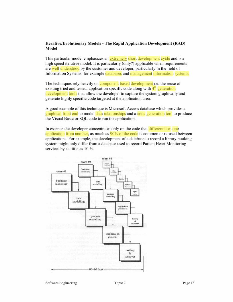
Iterative/Evolutionary Models - The Rapid Application Development (RAD) Model This particular model emphasizes an extremely short development cycle and is a high speed iterative model. It is particularly (only?) applicable when requirements are well understood by the customer and developer, particularly in the field of Information Systems, for example databases and management information systems. The techniques rely heavily on component based development i.e. the reuse of existing tried and tested, application specific code along with 4th generation development tools that allow the developer to capture the system graphically and generate highly specific code targeted at the application area. A good example of this technique is Microsoft Access database which provides a graphical front end to model data relationships and a code generation tool to produce the Visual Basic or SQL code to run the application. In essence the developer concentrates only on the code that differentiates one application from another, as much as 90% of the code is common or re-used between applications. For example, the development of a database to record a library booking system might only differ from a database used to record Patient Heart Monitoring services by as little as 10 %.
Paul
extremely
Paul
short
Paul
development
Paul
cycle
Paul
understood
Paul
well
Paul
databases
Paul
management
Paul
information
Paul
systems.
Paul
component
Paul
development
Paul
based
Paul
4th generation
Paul
development
Paul
tools
Paul
graphical
Paul
front
Paul
end
Paul
data
Paul
relationships
Paul
code
Paul
generation
Paul
tool
Paul
differentiates
Paul
one
Paul
application
Paul
from
Paul
another,
Paul
90% of the code
Software Engineering Topic 2 Page 14
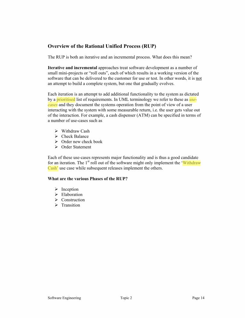
Overview of the Rational Unified Process (RUP) The RUP is both an iterative and an incremental process. What does this mean? Iterative and incremental approaches treat software development as a number of small mini-projects or “roll outs”, each of which results in a working version of the software that can be delivered to the customer for use or test. In other words, it is not an attempt to build a complete system, but one that gradually evolves. Each iteration is an attempt to add additional functionality to the system as dictated by a prioritised list of requirements. In UML terminology we refer to these as use-cases and they document the systems operation from the point of view of a user interacting with the system with some measurable return, i.e. the user gets value out of the interaction. For example, a cash dispenser (ATM) can be specified in terms of a number of use-cases such as
Withdraw Cash Check Balance Order new check book Order Statement
Each of these use-cases represents major functionality and is thus a good candidate for an iteration. The 1st roll out of the software might only implement the ‘Withdraw Cash’ use case while subsequent releases implement the others. What are the various Phases of the RUP?
Inception Elaboration Construction Transition
Paul
prioritised
Paul
usecases
Paul
Withdraw
Paul
Cash’

Software Engineering Topic 2 Page 15
What is meant by Inception? Inception establishes the case for the viability of the proposed system, e.g.
What are the objectives of the project? Can we make it? How much will it cost? What risks are involved? What is the window of opportunity for the product? What return will the customer see on their investment? Does it make sense from a business point of view?
It also attempts to produce an outline architecture for the system, in other words, what components will be used to build the system and how will they interact? What is meant by Elaboration? Elaboration expands upon the work done during inception and attempts to
Establish if the system can meet the expectations outlined during inception, e.g. deal with risk, cost, effect of technology and constraints.
Capture full functional requirements, i.e. get a detailed description of what the system mush do.
Create a detailed architecture to realise the requirements Prioritise risks and come up with a plan to address them (higher risks are
usually dealt with earlier in the project) Finalise a business case, i.e. convince the customer you can deliver the goods
on time and on budget. What is meant by Construction? Simply build a system, i.e. design and code a solution to the problems of inception and elaboration, prioritise the requirements and produce and decide on the functionality of the 1st release of the software. What is meant by Transition? Roll out the next version of the system to the customer Correct defects and unidentified problems
Paul
outline
Paul
architecture
Paul
full
Paul
functional
Paul
requirements,
Paul
risk,
Paul
cost,
Paul
constraints.
Paul
technology
Paul
detailed
Paul
architecture
Paul
business
Paul
case,
Paul
Correct
Paul
defects
Paul
next
Paul
version
Paul
build
Paul
system,
Software Engineering Topic 2 Page 16
Extreme Programming (XP) XP is a fairly new process model for software development and is summarised in Kent Beck’s book. Some of the important (some might say novel) aspects of XP are
It encourages very fast iterative development cycles leading to frequent releases of the code, typically in less than 1 week.
It attempts to instil into the mind of the programmer the idea that change is not something to be feared. This is based on the idea that object oriented technology has given rise to libraries of components that can be substituted and changed to meet different requirements with minimal knock on effects within the rest of the system. This is analogous to changing a light bulb in your house from 60 watt to 100 watt, the effect is minimal and the effects are limited to the lamp so the change should not be feared.
It attempts to instil in the programmer the idea that code should not be written until you have a test procedure to validate it against, in other words create your test cases first.
It encourages frequent rebuilding of the developing code base, sometimes maybe a dozen times a day. The purpose here is to perform almost continuous validation of the developed code against the previously written test suite. This gives encouragement to the programmer that they are doing it right and quickly picks up situations when they are doing it wrong.
It encourages an approach of “program for the here and know – not for the future”. In other words, if faced with a problem today, solve it today using the quickest (dirtiest ?) approach you can rather than research three different approaches before selecting the best. The success of this approach rests totally on the idea that the code can always be restructured and changed quickly (because of object based technology) if the algorithm/approach chosen was not sufficient for the task.
It encourages the placement of a customer on site during development to sit alongside the development team. The idea here is that the customer is a “domain expert”, i.e. someone who knows a lot about the business for which we are providing a solution and can act as a sounding board for developers.
Perhaps the most controversial aspect of the process is that it encourages pair-programming, i.e. developers working together rather than individually. Typically one types in the code and is thus focused on syntax, grammar, typing etc, while the other acts on strategy, algorithms and approach. He/she can also observe the other programmer as they type. This approach promotes several things
Communication and consideration of alternative strategies. Confidence and trust to try alternatives that they might not feel
justified in doing if working alone. Pair learning and debugging, i.e. each can learn from and assist the
other This should all lead to a better solution than if one person alone performed the task (well that’s the theory, some say it’s paying two people to do one persons job).
Paul
fast
Paul
iterative
Paul
development
Paul
1
Paul
week.
Paul
frequent
Paul
releases
Paul
change
Paul
is
Paul
not
Paul
something
Paul
feared.
Paul
test procedure to validate it against,
Paul
test
Paul
cases
Paul
first.
Paul
create
Paul
your
Paul
dozen
Paul
times
Paul
day.
Paul
rebuilding
Paul
code
Paul
base,
Paul
doing
Paul
it
Paul
right
Paul
doing
Paul
it
Paul
wrong.
Paul
Engineering Topic 2 Page 16
Paul
program for the here and know – not for the
Paul
future”.
Paul
totally
Paul
customer
Paul
on
Paul
site
Paul
domain
Paul
expert”,
Paul
sounding
Paul
board
Paul
developers.
Paul
pair-
Paul
programming,
Paul
syntax,
Paul
grammar,
Paul
typing
Paul
strategy,
Paul
algorithms
Paul
approach.
Paul
Communication
Paul
Confidence
Paul
Pair
Paul
learning
Paul
paying
Paul
two
Paul
people
Paul
do
Paul
one
Paul
persons
Paul
job).
Paul
libraries
Paul
of
Paul
components
Paul
consideration

Software Engineering Topic 2 Page 17
Analysis Techniques Now that we have seen each phase of the engineering design process described in simple terms, let us explore each phase in more detail. The chances of a product being developed on time and within budget are somewhat slim unless the members of the software development team agree on what the software product will do. Only after a clear picture of the present situation has been gained can the team attempt to answer the critical question:
“What must the new product be able to do?” The real objective of the requirements phase is to determine what software the client needs. This problem is exacerbated by the fact that many clients do not know what they need. Furthermore, even if the client has a good idea of what is needed, he or she may have difficulty in articulating these ideas to the developers, because most clients are less computer literate than the members of the development team. There is a famous quote uttered by a US politician back in the 60’s as he realised he’d dropped a gaff and was rapidly trying to back-peddle his way out.
"…I know you believe you understood what you think I said, but I am not sure you realise that what you heard is not what I meant!"
This excuse applies equally well to the issue of requirements analysis. The developers hear their client's requests, but what they hear is not what the client should be saying. Analysis Techniques
The principle objective of analysis is to uncover an understanding of the flow of information or data in the system, and/or its behaviour. That is, we seek an understanding of how information is transformed by the system, during its passage from input to output. We also seek to understand the systems interface characteristics and constraints e.g. this vending machine does not accept 'quarters'.
Analysis then attempts to uncover ‘what’ the product does, and ‘how it should behave’ it does not concentrate in any way on how the software will be implemented. That comes later. For example, analysis might concentrate on the following issues
• What data or events are input/recognised by the system? • What functions/transformations must the system provide? • What interfaces have been defined? • What constraints/limits apply?
Paul
What must the new product be able to do?”
Paul
"…I know you believe you understood what you think I said, but I am not sure you realise that what you heard is not what I meant!"
Paul
what software the client needs.
Paul
articulating
Paul
Analysis Techniques
Paul
flow
Paul
information
Paul
data
Paul
behaviour.
Paul
of
Paul
transformed
Paul
passage
Paul
characteristics
Paul
constraints
Paul
what’
Paul
how
Paul
it
Paul
behaves’
Paul
behave’
Paul
not
Paul
how
Paul
the
Paul
software
Paul
will
Paul
be
Paul
implemented.
Paul
events
Paul
functions/
Paul
transformations
Paul
interfaces
Paul
constraints/
Paul
data
Paul
do not know
Paul
interface
Paul
limits
Paul
on time
Paul
within budget
Paul
quarters'.
Software Engineering Topic 2 Page 18
Analysis Techniques
There is no one single analysis technique that is guaranteed to work and lead to a professional developed end product. Rather, several different techniques exist that are often combined, with each yielding up new information and understanding to the analyst. Here are some the most popular techniques that have a proven track record.
Technique 1 - Meetings and Discussions
One of the best initial analysis techniques is communication. Hold frequent discussions and reviews with the customer. This may sound obvious, but it is important to ask the right questions if it is going to be of use. Try using a combination of both open and closed questions with your customer. For example, an open question might ask them to explain what is wrong with their present arrangement, or to explain how the system should work. This will get them talking about the system and its solution from their point of view. You could also ask them to take you through astep-by-step sequence of typical operations, actions and/or calculations performed by the system, from initial input to final output to help understand the flow and sequence of data. Closed questions are designed to seek detailed clarification of specific points. For example, what resolution graphics card will be required? What is the format of the report produced by the program? How fast should the system be in dealing with data? As your understanding of the system grows, you will be able to pose lots of ‘What should happen when ‘X’ takes place’ questions to uncover the systems behaviour. Both types of questions can lead to an increased understanding of the system for both customer and developer alike. The result of such meetings is usually a written report, which the developer and customer agree or refine. Most important of all, don’t make assumptions about how the software should work, in the absence of a clear explanation. If necessary, go back to the customer, discuss any problems with them and seek clarification of any ambiguities. Technique 2 - Generate a Questionnaire Another way of gaining understanding is to send a questionnaire to the relevant members of the client organisation. This technique is useful when the opinions of, say, hundreds of individuals need to be determined like a microsoft product. Furthermore, a carefully thought-out written answer may be more accurate than an immediate verbal response to a question posed by an analyst. However, a meeting conducted by a methodical interviewer who listens carefully and poses questions that expand on initial responses will usually yield far better information than a thoughtfully worded questionnaire. However, because questionnaires are not interactive, there is no way that a new or modified question can be posed in response to an answer.
Paul
one single analysis technique
Paul
combined,
Paul
Meetings and Discussions
Paul
discussions
Paul
reviews
Paul
open
Paul
and
Paul
closed
Paul
questions
Paul
typical
Paul
operations,
Paul
actions
Paul
calculations
Paul
detailed
Paul
clarification
Paul
written report,
Paul
increased
Paul
understanding
Paul
customer
Paul
developer
Paul
assumptions
Paul
don’t
Paul
make
Paul
Generate a Questionnaire
Paul
hundreds
Paul
individuals
Paul
written
Paul
answer
Paul
accurate
Paul
verbal
Paul
response
Paul
interactive,
Paul
not
Paul
initial
Paul
communication.
Paul
resolution graphics
Paul
format
Paul
report
Paul
fast
Paul
clarification
Paul
far better information
Paul
‘What should happen when ‘X’ takes place’

Software Engineering Topic 2 Page 19
Technique 3 - Analyse the Customers Current Methods A different way of obtaining information, particularly in a business, production, or process control environment, is to examine the various forms, both input and output that are used by the client. For example, a form in a print shop might reflect press number, paper roll size, humidity, ink temperature, paper tension, and so on. A form used in a test facility might include a graphical print out for each component. This information exists for a reason and will help you to construct questions about its origin, purpose and importance to the system. Other documents, such as operating procedures and job descriptions, can also be powerful tools for finding out exactly how and what is done. Comprehensive information regarding how the client currently does business, can be extraordinarily helpful in determining the client's needs. Another method of obtaining such information is to set up video cameras within the workplace to record exactly what is being done. Technique 4 - Facilities, Application, Specification Techniques or FAST This technique encourages the customer and developer to work as a team to promote a rapid understanding of the system and its behaviour, the problems it poses and to propose solutions to them. The attraction of this scheme is that it produces information, which is of assistance in modelling the software, and will thus be useful to the designer/programmer later • Stage 1- The customer and analyst develop a “product request” which is
essentially a brief description of the system and what it will do in fairly loose terms.
• Stage 2- Before a meeting is held, each member of the team, which includes the
customer, is asked to examine the “product request” to create a list of objects (nouns) that are evident in the proposal. For example, consider the following extract:
“The user enters their data via a keyboard and the invoice
appears on the printer”. The objects thus identify the things the system will interact with i.e. the external devices, people or data in the system. Next, a list of operations are identified (verbs). For example
“The system processes the data, prior to formatting and displaying on the printer”.
Paul
Analyse the Customers Current Methods
Paul
forms,
Paul
used
Paul
by
Paul
the
Paul
client.
Paul
print
Paul
shop
Paul
press
Paul
number,
Paul
paper
Paul
roll
Paul
size,
Paul
humidity,
Paul
ink
Paul
temperature,
Paul
paper
Paul
tension,
Paul
exists for a reason
Paul
origin,
Paul
purpose
Paul
importance
Paul
operating
Paul
procedures
Paul
job
Paul
descriptions,
Paul
currently does business,
Paul
video
Paul
cameras
Paul
record
Paul
Facilities, Application, Specification Techniques or FAST
Paul
work as a team
Paul
rapid
Paul
understanding
Paul
modelling
Paul
the
Paul
software,
Paul
product
Paul
request”
Paul
examine
Paul
objects
Paul
keyboard
Paul
invoice
Paul
printer”.
Paul
interact
Paul
user
Paul
operations
Paul
nouns)
Paul
verbs).
Paul
processes
Paul
formatting
Paul
displaying
Paul
brief
Paul
description
Paul
devices,
Paul
people
Paul
data

Software Engineering Topic 2 Page 20
In essence these things identify the operations the software must perform and act on the objects identified previously. A similar process occurs in an attempt to identify any constraints imposed on the system for example:
“The system only accepts 5, 10, 20 and 50p coins”. Lastly, performance criteria are assessed, For example:
“The system must generate a response within 20mS”.
• Stage 3 - The members of the team (users, customers and developers) then meet and sit around a table and each in turn presents their findings. Common elements of each list are grouped together and refined into more detail in an attempt to elaborate the description of the item. This process may help uncover new objects,behaviour, constraints and performance criteria, or highlights ambiguities and/or deficiencies in existing elements. The discussion may raise issues that may not be answerable at that meeting, thus an issues list is kept to record all unresolved details or questions for future meetings.
• Stage 4 - Each member of the team then produces validation criteria against which the finished product can be assessed. That is data and results that can be used to check that the system performs according to the specification.
• Stage 5 - Finally, someone from the team is given the job of drafting a mini-
specification taking on board all aspects of the meeting.
The outcome of a FAST meeting is a mini-specification document as shown below.
Paul
operations
Paul
objects
Paul
constraints
Paul
performance
Paul
criteria
Paul
each in turn presents their findings.
Paul
grouped
Paul
refined
Paul
objects,
Paul
behaviour,
Paul
constraints
Paul
performance
Paul
ambiguities
Paul
deficiencies
Paul
issues
Paul
list
Paul
validation
Paul
criteria
Paul
assessed.
Paul
finished
Paul
product
Paul
data
Paul
results
Paul
specification.
Paul
performs
Paul
drafting
Paul
minispecification
Paul
mini-
Paul
specification
Paul
Common
Paul
elements
Software Engineering Topic 2 Page 21
Technique 5 - Design a Prototype.
A powerful technique for uncovering detail from the customer is to explore the concept of a prototype. Here the analyst presents a prototype model for the customer to evaluate. This could be something as simple as a paper and pencil model of the system showing how the user interacts with it. It could include a sequence of screen shots showing the appearance of the system performing critical operations, and perhaps the users input and the system responses to it. At a more detailed level, it could include a part-working prototype showing how the system might behave (although you should be careful to ensure that the customer realises that this is not the finished product). If the system is an enhanced version of a previous one, the prototype might then consist simply of a discussion of the enhancements/changes to the product.
Prototyping begins with requirements gathering. Developer and customer meet and define the overall objectives for the software, identify whatever requirements are known, and outline areas where further definition is required. A "quick design" then occurs. The quick design focuses on a representation of those aspects of the software that will be visible to the user. For example, inputs, outputs, operation and behaviour. Performance is not usually assessed at this stage. The quick design leads to the construction of a prototype. The prototype is evaluated by the customer/user and is used to refine requirements for the software to be developed. A process of iteration occurs
Reasons for Prototyping
• Customers often understand (or think they understand) the problem domain, that is, what they want to achieve with the system, but often have little appreciation of what the finished product will look like or how it will behave. Creating a prototype educates the customer and gives them an indication of what they can expect from the finished system.
• Customers hate surprises and frequently reject software based on how they see the software working and how effectively it solves their problems, not on how clever the code or the designers have been in creating it. Again, creating a prototype educates the customer and gives them an indication of what they can expect from the finished system.
• Seeing a prototype often serves to enhance an understanding of the problem domain and to uncover anomalies and ambiguities in its behaviour/operation. The earlier this is detected, the better for everyone.
Paul
prototype.
Paul
Design a Prototype.
Paul
prototype
Paul
model
Paul
customer
Paul
evaluate.
Paul
paper and pencil model
Paul
sequence of screen
Paul
shots
Paul
input
Paul
responses
Paul
part-
Paul
working
Paul
prototype
Paul
Prototyping
Paul
requirements
Paul
gathering.
Paul
quick design"
Paul
representation
Paul
aspects
Paul
software
Paul
visible
Paul
user.
Paul
of those
Paul
problem
Paul
domain,
Paul
what the finished product will look like or how it will behave.
Paul
educates
Paul
expect
Paul
finished
Paul
system.
Paul
hate
Paul
surprises
Paul
reject
Paul
software
Paul
not
Paul
expect
Paul
finished
Paul
system.
Paul
serves
Paul
enhance
Paul
understanding
Paul
uncover
Paul
anomalies
Paul
ambiguities
Paul
educates
Software Engineering Topic 2 Page 22
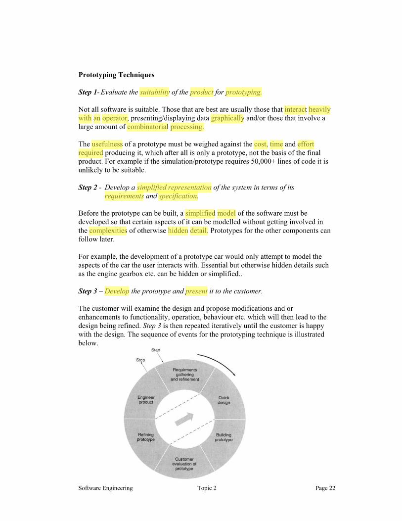
Prototyping Techniques Step 1- Evaluate the suitability of the product for prototyping. Not all software is suitable. Those that are best are usually those that interact heavily with an operator, presenting/displaying data graphically and/or those that involve a large amount of combinatorial processing. The usefulness of a prototype must be weighed against the cost, time and effort required producing it, which after all is only a prototype, not the basis of the final product. For example if the simulation/prototype requires 50,000+ lines of code it is unlikely to be suitable. Step 2 - Develop a simplified representation of the system in terms of its
requirements and specification. Before the prototype can be built, a simplified model of the software must be developed so that certain aspects of it can be modelled without getting involved in the complexities of otherwise hidden detail. Prototypes for the other components can follow later. For example, the development of a prototype car would only attempt to model the aspects of the car the user interacts with. Essential but otherwise hidden details such as the engine gearbox etc. can be hidden or simplified.. Step 3 – Develop the prototype and present it to the customer. The customer will examine the design and propose modifications and or enhancements to functionality, operation, behaviour etc. which will then lead to the design being refined. Step 3 is then repeated iteratively until the customer is happy with the design. The sequence of events for the prototyping technique is illustrated below.
Paul
suitability
Paul
product
Paul
prototyping.
Paul
interact
Paul
heavily
Paul
with
Paul
an
Paul
operator,
Paul
graphically
Paul
combinatorial
Paul
processing.
Paul
cost,
Paul
time
Paul
effort
Paul
required
Paul
usefulness
Paul
simplified representation
Paul
requirements
Paul
specification.
Paul
simplified
Paul
model
Paul
complexities
Paul
hidden
Paul
detail.
Paul
Develop
Paul
present
Software Engineering Topic 2 Page 23
The introduction of 4th Generation programming tools can help here to provide a rapid user interface for the user to view and see how the system looks e.g. Visual basic and Visual C++ are both rapid development tools and quickly generate a user interface.
Step 4 - Throw away the prototype
The results of prototyping can be very important to the final design of the software. In fact, if the prototype is accurate enough in modelling the behaviour and functionality of the required system, it may only be necessary to say to the designer, “design a system that work like this”.
However, it is important to appreciate that if the prototype was in the form of software it has to be “thrown away”, as it was probably only held together by luck and flaky code in the first place.
It is vital that we do not lead the customer (or the developer) to believe that with a bit of effort, the prototype can be coerced into becoming the finished product. This would raise false expectations about delivery dates of the finished product and might ask them to question how you can justify charging so much for developing the finished product when with just a few weeks of effort the product looks like it might already exist. Analysis Technique 6 – Data and Function Modelling One of the more powerful analysis techniques that can be applied, usually after other preliminary analysis techniques have been completed and the developer/analyst has acquired a sound understanding of the functionality and behaviour of the system, is to model the flow of information during its passage through our system. This aspect of analysis was touched on briefly in analysis technique 4 – FAST
To understand the technique, sit back and think of a computer system as nothing more than a black box with inputs and outputs. With this in mind, it becomes possible to view the system as nothing more than one large ‘transform’. That is, it takes data in, processes or transforms it into new data and then outputs it. For example, the action of calculating the area of a circle could be thought of as a single transform, which takes in data about the radius of the circle and transforms it via simple mathematical operation into data, which represents the area. Two such transforms could thus be employed to calculate both the area and the circumference. Getting slightly more sophisticated, the outputs of these transforms could then become the inputs of further transforms that modify the data further. For example, it is easy to envisage a transform that formats data prior to displaying it. A way useful method of modelling this flow, graphically, is to represent it in the form of Data Flow Diagrams (DFD’s) which identify the various data flows and transformations that occur as data enters and leaves the our system. Data flow
Paul
Throw away the prototype
Paul
design a system that work like this”.
Paul
important
Paul
results
Paul
prototyping
Paul
accurate
Paul
thrown
Paul
away”,
Paul
luck
Paul
flaky
Paul
code
Paul
customer
Paul
coerced
Paul
prototype
Paul
finished
Paul
product.
Paul
Data and Function Modelling
Paul
model
Paul
flow
Paul
information
Paul
the
Paul
of
Paul
during
Paul
its
Paul
passage
Paul
through
Paul
our
Paul
system.
Paul
black box
Paul
inputs
Paul
outputs.
Paul
transform’.
Paul
takes data in,
Paul
processes
Paul
transforms
Paul
new
Paul
data
Paul
then
Paul
outputs
Paul
calculating the area of a circle
Paul
radius
Paul
mathematical
Paul
operation
Paul
represents
Paul
area.
Paul
area
Paul
circumference.
Paul
formats
Paul
Data Flow Diagrams

Software Engineering Topic 2 Page 24
diagram are often supplemented by Control flow diagrams (CFD’s) when the system is essentially event driven, that is, transforms are activated by external events. A good example of an event driven system is a Stopwatch, VCR, or CD player. Here the user’s interaction triggers new operations and behaviour. We shall see this technique in use later in the course. It is important because there exist techniques to translate the resultant DFD and CFD models into a program structure, which is after all, the name of the game.
Analysis Technique 7 - Write a Specification for the system
Whichever of the previous analysis techniques are ultimately chosen or combined, a specification or requirement document must ultimately be drawn up. Ideally the customer would provide this, but it is more often developed jointly. The specification should include the following, which should hopefully have been uncovered during analysis:
• Behaviour, I/O, functionality, performance, • User interfaces, any formal specifications and any prototype models. • Verification and Validation data should also be included
Verification and Validation data is important in assessing the developed product and is usually developed by the customer. In simple terms such data will include.
1. Sample inputs that can be used to exercise the working system.
2. Sample expected outputs that can be used to measure the effectiveness of the implementation.
3. Sample errors or events that the system is expected to process.
The validation data could be in the form of a formula, print outs, special case descriptions, and error trapping and responses to events. The way a system deals with errors or unexpected data is just as important as the way it deals with correct or predicted input and should be part of the specification.
Ideally sufficient validation data should be produced to completely exercise the machine and this could be used to determine if the system meets the specification. This is very important, as it effectively gives the analyst and designer a ‘rod’ to beat each other with if the system doesn’t work.
In other words, it is a means of checking that the system behaves in a way agreed by both parties, either of which could be liable if the system fails.
Paul
Control flow diagrams
Paul
event
Paul
driven,
Paul
Stopwatch,
Paul
VCR,
Paul
CD
Paul
event
Paul
interaction
Paul
Write a Specification for the system
Paul
specification
Paul
requirement
Paul
document
Paul
• Behaviour, I/O, functionality, performance, • User interfaces, any formal specifications and any prototype models. • Verification and Validation data should also be included
Paul
Verification
Paul
Validation
Paul
inputs
Paul
exercise
Paul
outputs
Paul
effectiveness
Paul
errors
Paul
events
Paul
gives the analyst and designer a ‘rod’ to beat
Paul
each
Paul
other
Paul
validation
Paul
data

Software Engineering Topic 2 Page 25
Creating the Specification Document There is nothing worse for a system developer than an inaccurate or incomplete specification. It leads to frustration, low productivity, increased development cost and slipping time scales. The resultant quality of the software also suffers as a result. So how do you draft a system specification? 1. Separate functionality from implementation
The specification should only describe what the system should do, not how it will be done in the system.
2. The specification must encompass all aspects of the system, particularly the environment in which the software will work. The specification must relate how the software interacts with the entire system. It is not sufficient to say that it “Reads a product code”. It must say things like “It reads the product code as a two digit letter/number code in the range a-f,0-9 from a 16 key ‘product selection’ data entry keyboard fixed to the front panel of the system”
3. The specification must describe the system from the user point of view. For example it might state things like. “In order to request an elevator, the user has two options. i) They can press either or both of the up of down request arrows situated outside the elevator, on each floor, or ii) they can press one or more of the floor request buttons located inside each elevator,
4. The specification must be precise enough for the designer to be able to build the system from the results of the modelling.
5. The specification must be loosely coupled. That is it must be structured such
that changes to one aspect of the specification have minimal effect on the specification elsewhere. For example, if the specification repeatedly makes reference to a 16 digit LCD display and then says things like, “the results will be formulated such that the product code uses the 1st 8 digits and the price occupies the last 4 digits with 4 spaces between”, then, the effect of changing the specification for the LCD has a ripple effect right through the specification
Paul
system
Paul
developer
Paul
inaccurate
Paul
incomplete
Paul
specification.
Paul
what
Paul
not
Paul
how
Paul
interacts
Paul
Reads a product code”.
Paul
It reads the product code as a two digit letter/number code in the range a-f,0-9 from a 16 key ‘product selection’ data entry keyboard fixed to the front panel of the system”
Paul
user
Paul
point
Paul
of
Paul
view.
Paul
all aspects
Paul
environment
Paul
functionality
Paul
implementation
Paul
designer
Paul
build
Paul
system
Paul
DFD
Paul
modelling.
Paul
loosely
Paul
coupled.
Paul
changes
Paul
one
Paul
aspect
Paul
minimal
Paul
effect
Paul
repeatedly
Paul
makes
Paul
reference
Paul
1st 8 digits
Paul
last 4 digits
Paul
4 spaces between”,
Paul
changing
Paul
specification
Paul
LCD
Paul
ripple
Paul
effect
Paul
up
Paul
down

Software Engineering Topic 2 Page 26
Requirement specification - Draft a User Manual It might seem a little premature at this stage, but it is actually very profitable to produce a user manual early on. However, this forces both parties to focus attention on the user interface and behaviour of the system as perceived by its eventual users and this will have a profound effect on the design. Draw up a Contract Finally, once the analysis has been completed, the specification is “signed-off” and a contract is drawn up for software development. Changes in requirements requested after the specification has been finalised will not be eliminated, but the customer must realise that each modification made after the ‘sign-off’ date is an extension of the agreed specification and therefore can lead to increased costs and delays in delivery
Paul
Draft a User Manual
Paul
Contract
Paul
user
Paul
manual
Paul
user
Paul
interface
Paul
behaviour
Paul
system
Paul
perceived
Paul
users
Paul
signed-off”
Paul
Changes
Paul
requirements
Paul
finalised
Paul
after
Paul
eliminated,
Paul
specification
Software Engineering Topic 2 Page 27
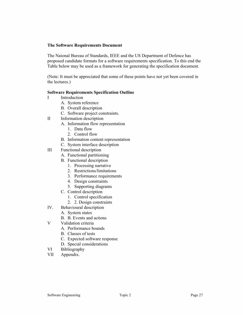
The Software Requirements Document The Naional Bureau of Standards, IEEE and the US Department of Defence has proposed candidate formats for a software requirements specification. To this end the Table below may be used as a framework for generating the specification document. (Note: It must be appreciated that some of these points have not yet been covered in the lectures.) Software Requirements Specification Outline I Introduction
A. System reference B. Overall description C. Software project constraints.
II Information description A. Information flow representation
1. Data flow 2. Control flow
B. Information content representation C. System interface description
III Functional description A. Functional partitioning B. Functional description
1. Processing narrative 2. Restrictions/limitations 3. Performance requirements 4. Design constraints 5. Supporting diagrams
C. Control description 1. Control specification 2. 2. Design constraints
IV. Behavioural description A. System states B. B. Events and actions
V Validation criteria A. Performance bounds B. Classes of tests C. Expected software response D. Special considerations
VI Bibliography VII Appendix.


![Software Processes [Sommerville]](https://static.fdocuments.net/doc/165x107/586a20621a28abf7678b6f5a/software-processes-sommerville.jpg)


