
SMART AUTOMATED HOME MEGAT IZZUDDIN BIN MEGAT...
156
SMART AUTOMATED HOME MEGAT IZZUDDIN BIN MEGAT AB MANAP MAY 2008
Transcript of SMART AUTOMATED HOME MEGAT IZZUDDIN BIN MEGAT...

SMART AUTOMATED HOME
MEGAT IZZUDDIN BIN MEGAT AB MANAP
MAY 2008

“I hereby declared that I have read through this report and found that it has comply
the partial fulfillment for awarding the degree of Bachelor of Electrical Engineering
(Control, Instrumentation & Automation)‖
Signature : …………………………………
Supervisor’s Name : Jurifa Bt Mat Lazi
Date : 6 May 2008

SMART AUTOMATED HOME
MEGAT IZZUDDIN BIN MEGAT AB MANAP
This Report Is Submitted In Partial Fulfillment of Requirements for the Degree of
Bachelor in Electrical Engineering (Control, Instrumentation & Automation)
Faculty of Electrical Engineering
Universiti Teknikal Malaysia Melaka
May 2008

DECLARATION
―I hereby declared that this report is a result of my own work except for the
excerpts that have been cited clearly in the references.‖
Signature : ………………………………………
Name : MEGAT IZZUDDIN BIN MEGAT AB MANAP
Date : 6 MAY 2008

DEDICATION
For my beloved father, Megat Abd Manap Bin Megat Husain and mother,
Arbaah Bte Mat Said, my brother and sister

ACKNOWLEDGEMENTS
First of all, I would like to express my thankfulness to Allah S.W. T who has
given me the strength, knowledge and capability to implement and complete my Projek
Sarjana Muda and also to complete this report.
I would like to express my highest and foremost gratitude to my project
supervisor, Puan Jurifa Bt Mat Lazi for her guidance, help and advices to complete this
project. Next, I would like to thank Malaysian Coal Integrated Engineering Services
(MCIE), the company which I had my industrial training attachment with for their
sponsorship of equipments and devices which I used for my project. I would also like to
thank the Faculty of Electrical Engineering (FKE), Universiti Teknikal Malaysia Melaka
(UTeM) for giving me the opportunity to implement and complete my project.
Next, I would like to thank my parents for their financial and support and also to
my fellow friends in 4BEKC. Last but not least, I would like to thank everyone who is
directly and indirectly involved in this project. Their support and encouragement has
given me the strength and effort to complete this project. Thank you.

ABSTRACT
This project is about the construction of an automated control system for a smart
home to control critical house parameters, which includes the indoor and outdoor
lightings, indoor ventilation, garbage management, garden watering, garage/parking and
events alert. The outdoor lightings are automatically activated when the day gets dark by
using a dark detection circuit. The indoor lightings are equipped with dimmers and the
switches are relocated to more strategic locations. The indoor ventilation is connected to
a temperature sensing circuit which controls a pair of ventilation fans to lower the indoor
temperature. The garbage management automatically takes care of the garbage according
to the collection schedule. The garden watering will be automatically activated according
the time. The garage/parking system are designed to be safer and more convenient for the
occupants while the event alert warns its occupant of possible danger. The operation for
each parameters are represented on a scale model. The system utilizes the use of
Programmable Logic Controller (PLC) and Integrated Circuit (IC) to create an
interconnected control system. Each system are connected with other common input and
output devices such as motors, switches, sensors, lights, relays etc.

ABSTRAK
Projek ini adalah berkenaan tentang pembinaan suatu sistem kawalan automatik
utk rumah pintar untuk mengawal bahagian-bahagian penting rumah termasuklah lampu
dalaman dan lampu luaran, ventilasi dalam rumah, pengurusan sampah, pengairan taman,
tempat letak kereta dan juga amaran awal. Lampu luar boleh dihidupkan secara automatik
mengunakan litar mengesan kepekaan cahaya. Lampu dalaman pula telah dilengkapi
dengan pemalap dan suis akan ditempatkan semula di tempat yang lebih strategik.
Ventilasi dalam rumah akan disambungkan dengan litar pengesan kepekaan haba yang
mengawal sepasang kipas ventilasi utk menurunkan suhu di dalam rumah. Pengurusan
sampah pula menguruskan sampah mengikut waktu kutipan sampah. Pengairan taman
juga akan dihidupkan secara automatik mengikut waktu. Tempat letak kereta akan direka
untuk menjadi lebih selamat dan lebih mudah untuk penghuni manakala amaran awal
memberi amaran tentang bahaya yang bakal menimpa. Operasi untuk setiap bahagian
diwakilkan pada model skala. Sistem ini akan mengaplikasikan pengunaan Pengawal
Logik Aturcara (PLC) dan Litar terbina dalam (IC) untuk mencipta suatu sistem kawalan.
Setiap sistem disambungkan dengan input dan output seperti motor, suis, sensor, lampu,
geganti dan lain-lain.

TABLE OF CONTENTS
CHAPTER CONTENTS PAGE
TITLE PAGE i
DECLARATION ii
DEDICATION iii
ACKNOWLEDGEMENTS iv
ABSTRACT v
ABSTRAK vi
TABLE OF CONTENTS vii
LIST OF FIGURES xiii
LIST OF TABLES xv
LIST OF APPENDICES xvi
LIST OF ABBREVIATIONS xvii
1 INTRODUCTION
1.1 Project Background 1
1.2 Problem Statement 3
1.2.1 General Problem Statement 3
1.2.2 Detailed Problem Statement 4
1.3 Project Objective 4
1.4 Project Scope 5
1.5 Project Advantages & Benefits 6
2 LITERATURE REVIEW
2.1 Case study 7
2.1.1 The Home Depot Smart Home 7
2.1.2 The purpose of building the Home Depot Smart 8
Home at Duke
2.1.3 The Duke Smart Home Program 9
2.1.4 Benefits of the Duke Smart Home Program 10
2.1.5 Accessibility in The Home Depot Smart Home 12
2.1.6 Cooling Systems for The Home Depot Smart 12
Home
2.1.7 Daylighting 12
2.1.8 Fire Safety 13
2.1.9 Geothermal Pump 13
2.1.10 Indoor Air Quality Monitoring 13
2.1.11 Leadership in Energy and Environmental Design 13
(LEED)
2.1.12 Media-on-Demand 14
2.1.13 Photovoltaic System Design 14
2.1.14 Protecting Public Health – UV Disinfection 14
of Drinking Water
2.1.15 Recycling 15
2.1.16 Retractable Roof 15
2.1.17 RFID Technology 15
2.1.18 Security 16
2.1.19 Soundproofing and Acoustic Suggestions 16
2.1.20 Water Catchment, Purification/ Rainwater 16
Harvesting
2.1.21 Adaptive Digital Signal Processing – Active 16
Noise Filtering
2.1.22 Facial Recognition 17
2.1.23 Advanced HVAC Control and Artificial 17
Intelligence Controllers
2.1.24 LED Lighting 17
2.1.25 Residential Piezoelectric Energy Sources 17
2.1.26 Sensor Platform 18
2.1.27 Shower Heat Recovery 18
2.1.28 Sleep Monitoring 18
2.1.29 Home Automation 19
2.2 Conclusion 19
3 METHODOLOGY
3.1 Overview 20
3.1.1 Literature review 20
3.1.2 Design the modules and circuits 20
3.1.3 Simulate circuits 20
3.1.4 Redesign circuits 21
3.1.5 Purchase components 21
3.1.6 Assemble circuits 21
3.1.7 Test operation 21
3.1.8 Troubleshoot 21
3.1.9 Assemble the modules 22
3.1.10 Test operation 22
3.1.11 Improvements, modifications and additions 22
3.1.12 Analysis 22
3.1.13 Connect the assembled modules 22
3.1.14 Test operation 23
3.1.15 Finalize 23

3.2 Flowchart 24
3.3 Gantt chart 26
4 PROJECT BACKGROUND
4.1 Introduction 27
4.1.1 Smart Home 27
4.1.1.1 Functions of smart home system 28
4.1.1.2 Benefits of smart home system 29
4.2 Project Background 30
4.2.1 Indoor Lighting 30
4.2.1.1 Overview 30
4.2.1.2 Design 30
4.2.1.3 Circuit 32
4.2.1.4 Hardware and software 33
4.2.2 Outdoor Lighting 34
4.2.2.1 Overview 34
4.2.2.2 Design 34
4.2.2.3 Circuit 35
4.2.2.4 Hardware and software 38
4.2.3 Indoor Ventilation 39
4.2.3.1 Overview 39
4.2.3.2 Design 39
4.2.3.3 Circuit 41
4.2.3.4 Hardware and software 42
4.2.4 Garbage disposal 44
4.2.4.1 Overview 44
4.2.4.2 Design 45
4.2.4.3 Circuit 46
4.2.4.4 Hardware and software 46
4.2.5 Garage and car park 50
4.2.5.1 Overview 50
4.2.5.2 Design 50
4.2.5.3 Circuit 53
4.2.5.4 Hardware and software 53
4.2.6 Events alert 58
4.2.6.1 Overview 58
4.2.6.2 Design 58
4.2.6.3 Circuit 59
4.2.6.3.1 Water Level Sensor 59
4.2.6.3.2 Heat Sensing 61
4.2.6.3.3 Smoke Sensor 62
4.2.6.3.4 Buzzer Interval 64
4.2.6.4 Hardware and software 65
4.2.7 Garden Management 68
4.2.7.1 Overview 68
4.2.7.2 Design 68
4.2.7.3 Circuit 69
4.2.7.4 Hardware and software 70
4.3 Components 71
4.3.1 Programmable Logic Controller (PLC) 71
4.3.1.1 Introduction to PLC 71
4.3.1.2 Features of PLC 72
4.3.1.3 Comparing PLC with other control 73
systems
4.3.1.4 Programming 75
4.3.2 Omron ZEN 76
4.3.2.1 Features 76

4.3.2.2 Programming 76
4.3.2.3 Functions 77
4.3.2.4 Expansion 77
4.3.2.5 Support software 78
4.3.3 Integrated circuit (IC) 79
4.3.3.1 Introduction 79
4.3.3.2 History of ICs 79
4.3.3.3 Advantages of ICs 80
4.3.3.4 Popularity of ICs 80
4.3.3.5 Classifications of ICs 80
4.3.4 555 Timer IC 81
4.3.4.1 Introduction 81
4.3.4.2 Inputs of 555 83
4.3.4.3 Outputs of 555 84
4.3.4.4 555 Astable 84
4.3.5 741 Op-Amp IC 85
4.3.5.1 Introduction 85
4.3.5.2 Definition of 741 pin functions 86
4.4 Project Costs & Expenses 87
5 RESULT & DISCUSSION
5.1 Result 89
5.2 Discussion 90
5.2.1 Problems & Challenges 90
6 CONCLUSION & RECOMMENDATIONS
6.1 Recommendations 92
6.2 Conclusion 93

REFERENCES 94
APPENDICES 95
LIST OF FIGURES
FIGURE TITLE PAGE
1.1 Block Diagram of control system using PLC and IC 1
2.1(a) The Home Depot Smart Home 7
3.2 Project flow chart 24
3.3 Gantt chart 26
4.1(a) A smart home system 28
4.2.1(a) Block diagram for Indoor Lighting 30
4.2.1(b) Assembled circuit for the Indoor Lighting 32
4.2.1(c) Light dimmer circuit using PWM control method 32
4.2.2(a) Block diagram for Outdoor Lighting 34
4.2.2(b) Assembled circuit for the Outdoor Lighting 35
4.2.2(c) IC 555 Timer pin allocations 35
4.2.2(d) Internal circuit for IC 555 Timer 36
4.2.2(e) Light/dark sensing circuit for Outdoor Lighting 36
4.2.3(a) Block diagram for Indoor Ventilation 39
4.2.3(b) Wheatstone Bridge 40
4.2.3(c) Assembled circuit for Indoor Ventilation 41
4.2.3(d) Temperature sensing circuit for Indoor Ventilation 41

4.2.3(e) 12VDC CPU fan rated at 0.13A 43
4.2.3(f) Temperature display unit 43
4.2.4(a) Block diagram for garbage disposal 45
4.2.4(b) Concept diagram for garbage disposal 45
4.2.4(c) Ladder diagram for overall Garbage Disposal module 48
4.2.4(d) Inductive proximity sensor used for platform position 48
4.2.4(e) AC Synchronous motor used for platform rotation 49
4.2.5(a) Concept diagram for garage and car park 50
4.2.5(b) Block diagram for garage and car park 51
4.2.5(c) Limit switch and triangular marker 52
4.2.5(d) Rotating platform 52
4.2.5(e) Optical distance sensor 54
4.2.5(f) Ladder diagram for garage door 56
4.2.5(g) Ladder diagram for rotating platform 57
4.2.6(a) Block diagram for Events Alert 58
4.2.6(b) Assembled circuit for Water Level Sensor 59
4.2.6(c) Water Level Sensor circuit for Events Alert 60
4.2.6(d) Assembled circuit for Heat Sensing 61
4.2.6(e) Heat Sensing circuit for Events Alert 61
4.2.6(f) Assembled circuit for Smoke Sensor 62
4.2.6(g) Smoke Sensor circuit for Events Alert 63
4.2.6(h) Assembled circuit for Buzzer Interval 64
4.2.6(i) Buzzer Interval circuit for Events Alert 64
4.2.7(a) Block diagram for Garden Management 68
4.2.7(b) Ultrasonic pest repellant circuit for Garden Management 69
4.3.1(a) PLC and input/output arrangements 71
4.3.1(b) Control Panel with PLC 72
4.3.2(a) Multi function and space saving features 76
4.3.2(b) Programming the Omron ZEN 76
4.3.2(c) Expansion units 77
4.3.2(d) Support software 78

4.3.3 Integrated circuit 79
4.3.4(a) Actual pin arrangements 81
4.3.4(b) Example circuit symbol 83
4.3.4(c) 555 Astable output, a square wave 84
4.3.4(d) 555 Astable circuit 85
4.3.5 741 Op Amp pin functions 86
5.1 Completed project 89
LIST OF TABLES
TABLE TITLE PAGE
4.3(a) Purchased hardware total cost 87
4.3(b) Sponsored hardware total cost 88
4.3(c) Total cost for purchased and sponsored hardware 88
LIST OF APPENDICES
APPENDIX TITLE PAGE
A UTeMEX poster 96
LM555 Single Timer datasheet 97
LM741 Operational Amplifier datasheet 109
Optical distance sensor datasheet 116
Omron ZEN features catalog 118
LIST OF ABBREVIATIONS
ABBREVIATIONS MEANING
CCTV Closed circuit television
DC Direct current
AC Alternating current
IC Integrated circuit
LCD Liquid crystal display
LDR Light dependant resistor
LED Light emitting diode
PLC Programmable logic controller
PIC Programmable interface controller
PWM Pulse Width Modulation
NO Normally open
NC Normally close
CHAPTER 1
INTRODUCTION

1.1 Project Background
This chapter provides the necessary background for this project, which explains
the basic principle of PLC and IC control system.
Figure 1.1: Block Diagram of control system using PLC and IC
To create a control system, it must have 3 basic components which are input,
process and output. The process consists of the PLC and IC which acts as input signal
processing device to control the output. A brief introduction to the concept of application
is given to provide basic understanding of this project.
The input device comes in the form of ordinary on/off limit switches, push
buttons, variable resistors, photo-electric sensors, proximity sensor, light dependent
resistors (LDR) and thermistors. These devices provide the activation signal in the form
of analog or digital signal to the control unit.
The controller part which is the PLC and the IC acts as the primary control unit
for this project. In this system, the PLC controller used is the Omron ZEN micro PLC
unit. The input signals are transmitted digitally into the PLC and an appropriate
INPUT DEVICE
PLC
IC
OUTPUT DEVICE

―decision‖ will be made by the PLC according to the programmed ladder logic diagram.
The PLC will then produce a digital signal in the form of relay output. The PLC is chosen
over PIC to provide control for this project due to its multiple inputs and output
arrangements and also its easy and user friendly programming using ladder logic
diagram. The key feature for the PLC that is used is the built in daily, weekly and
monthly timer capability which provides useful control for time controlled operation.
The IC is used for analog signal processing which involves decision making
through logic gates combination and comparing two or more sets of input signals. There
are two main advantages of ICs over discrete circuits which is the cost and performance.
Cost is low because the chips, with all their components, are printed as a unit by
photolithography and not constructed a transistor at a time. Performance is high since the
components switch quickly and consume little power, because the components are small
and close together.
For this project, the control is divided into two control devices which are the PLC
and the IC. The purpose for this design is to fully utilize the advantages of both devices.
The PLC has the advantage of easy programming, multiple relay outputs and enables
systematic & organized wiring to be implemented. The IC on the other hand has the
advantage of miniature size, low costs and provides tons of function according to the
circuit it is connected. By combining two forms of these widely used devices, a good and
reliable control system can be created to cater the project’s needs.
The output device will be in the form of relays, buzzer, DC motors, tweeter,
lights, LEDs and fans. These devices receive activation signal from the PLC, IC or
directly from the input device and perform various functions including illumination,
cooling and etc.
1.2 Problem Statement

This project like all others is created to solve problems that we humans encounter
everyday. Upon completion of this project, the problems that we face will hopefully be
solved or at least reduced. To make it easier to explain regarding the problem statements,
they are divided into two parts, which is general aspect and detailed according to the
system arrangements
1.2.1 General Problem Statement
There is no training kit that emphasizes the combination between PLC and
electronics based circuits.
Most training kit available focuses on industrial system but not home
automation system.
Available home automation has limited control over devices/system and
costly.
Normal homes are inconvenience, not safe and not economical.

1.2.2 Detailed Problem Statement
For the indoor lightings, the lights switches are located far away, not easily to
access locations and the lights cannot be dimmed.
The outdoor lights needs to be turned on and off manually at day & night and
sometimes the occupant forgot to turn them off. This causes wastage in
electricity bills.
The temperature inside (indoor) are hot and unpleasant. The hot/warm air is
trapped inside house due to poor ventilation
The occupant missed the weekly garbage collection time and the garbage
spilled when bringing it outside the house. Furthermore, the odor from the
garbage attracts flies & disease.
Plants at the garden die due to lack of watering and the gardens are infected
by pests.
Accidentally hit the garage wall/children while reversing the vehicle and
sometimes the occupant forgets to close the garage door
House does not have fire and flood warning system.
1.3 Project Objective
The objective of this project is to design & construct a control system
which consists of home automation and lighting control that can be used for various
purpose especially teaching & learning and home application.
The lighting control is used to control the illumination and brightness for
the indoor and outdoor lightings while the home automation is used to control the indoor
ventilation, garbage disposal, garden management, garage/car park and events alert.

1.4 Project Scope
Scope and limitations for this project:
Design and construction of a control system consist of home automation and
lighting control.
Constructed using PLC, Electronic circuits, DC motors, sensors, switches,
relays etc.
The model design & construction consists of small scale model that represents
the connection and function of the system.
System powered by DC source through switching power supply and voltage
regulators.
Lighting
i. Indoor
ii. Outdoor
Home automation
i. Ventilation (Indoor)
ii. Garbage disposal
iii. Garden management
iv. Garage/car park
v. Events alert
1.5 Project Advantages & Benefits
There are many advantages and benefits for the implementation of this
project. A simple yet effective lighting control and home automation system is created.
The control and automation system is easy to troubleshoot for problems and easy to
improve or upgrade the system in the future. The system is also user friendly and safe
that is usable by all ages including children as a system should be easy to control and
handled by everyone. The system creates a low cost home automation system that is
affordable by everyone so that everyone can experience the advancement in modern
technology.
The system also makes efficient use of electricity by optimizing and minimizing
the usage hours of lightings and ventilations system through automatic turn on and turn
off system. Electricity bills and power wastage will be reduced and ensures a prolonged
life span of electrical devices through optimized working hours. Lights and fans turn on
only when needed.
This project is also aimed as an educational tool in the classroom which provides
a more interesting approach and better understanding on the application of automation for
homes.
CHAPTER 2
LITERATURE REVIEW
2.1 Case Study
The case study for this project is based on the Home Depot Smart Home
constructed by Duke's Pratt School of Engineering.
2.1.1 The Home Depot Smart Home
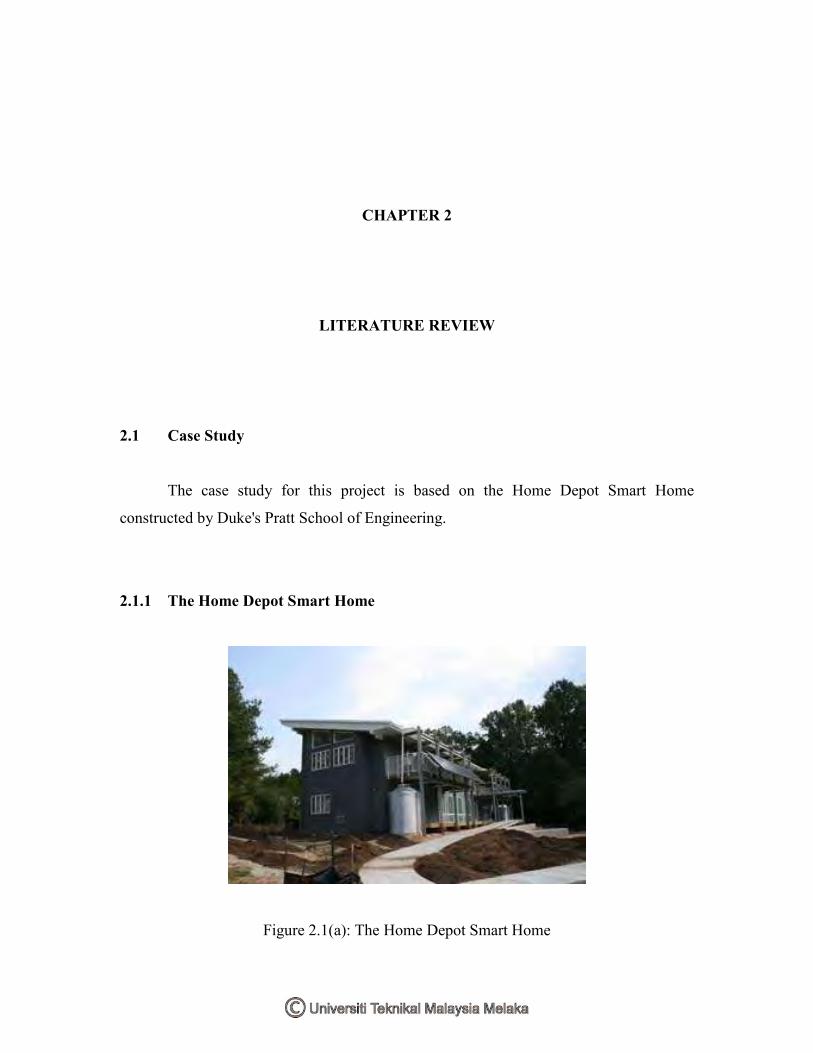
Figure 2.1(a): The Home Depot Smart Home

The Home Depot Smart Home is a 6,000 square foot live-in research laboratory
operated by Duke's Pratt School of Engineering. The Home Depot Smart Home, part of a
Duke Smart Home Program, creates a dynamic "living laboratory" environment that
contributes to the innovation and demonstration of future residential building technology.
The central concept of this project is our belief that smart homes can improve that quality
of life for people of all ages and incomes.
The Home Depot Smart Home provides students at Duke's Pratt School of
Engineering, Trinity School of Arts and Sciences and Nicholas School for the
Environment and Earth Sciences with an opportunity for practical hands- on engineering
outside of the classroom in a living and learning community. In addition, the partnering
with industry to strengthen the residential market for integrated technology, and helping
homeowners make their own ideas for smart homes a reality.
The goals for the residents of The Home Depot Smart Home are to:
a) Commit to and explore an energy efficient lifestyle,
b) Compare, use and develop smart and sustainable technology, and
c) Provide insight to homeowners for "do-it-yourself" technology integration and
control.
2.1.2 The purpose of building the Home Depot Smart Home at Duke
Other universities already have smart homes, so why build another one at Duke?
One of the most important aspects of this project is that it is a living laboratory--students
will actually reside in The Home Depot Smart Home, and live with the benefits and
consequences of their technology design and deployment decisions. This up close and
personal approach to technology development will have a profound impact on the
students--and on industry as Pratt engineers graduate and launch their own careers. The
intention is to share the experiences and technology innovations and draw upon the
experiences of other university Smart Home projects. The long term goal is to influence
the national market for residential technology integration, and to help educate
homeowners about the latest technologies.
2.1.3 The Duke Smart Home Program
The Duke Smart Home Program is a research-based approach to smart living
sponsored by the Pratt School of Engineering. Primarily focused on undergraduates, the
program encourages students from different academic disciplines to form teams and
explore smart ways to use technology in the home. The emphasis on 'smart' means
finding the best technology answer for a particular problem--not just finding the high tech
solution or the latest gadget on the market. This approach naturally leads students to
identify 'gaps' in the marketplace--problems that just aren't being addressed through
commercially available technology. These gaps then become the basis for exploration.
The Duke Smart Home Program encompasses a 6,000 sq. ft. residential dorm and
research laboratory called the Home Depot Smart Home; a thriving student club of Duke
students who explore smart home technology design and prototyping (some projects are
directly related to the dorm), a growing core of faculty to conduct research that parallels
the goals of the Duke Smart Home Program, and an enthusiastic community of members
of industry who see this program as a unique way to cultivate the next generation of
employees and to augment their own consumer technology R&D efforts. Hopefully,
others will see sustainable living research at Duke continue expand to include students
from all disciplines of academic study. In addition, to stimulate faculty across Duke to
participate in research focused on technology adoption, energy efficiency, and
environmental sustainability.
The Duke Smart Home Program fosters strong relationships with industry through
collaborative projects, tours and interviews, guest lectures and internships. Hopefully, to
not only strengthen the market for integrated technology, but to also help homeowners
make their own ideas for smart home a reality. The central concept of this project is the
belief that smart homes can improve that quality of life for people of all ages and
incomes.
The Duke Smart Home Program provides students with outlets for:
a) Hands-on technology exploration and optimization,
b) Project management, team building and design experience,
c) Study of technology adoption and design refinement,
d) Study of product marketability, economics and practical engineering aspects
of product design, and exploring the gap between commercial versus
consumer technology and shaping the future of smart residential living.
2.1.4 Benefits of the Duke Smart Home Program
a) Provides Practical Design Experience - One of the biggest challenges for
universities is involving students in hands-on engineering experiences early in
the curriculum. Design and application of design is the most fundamental skill
of engineering, yet at many universities, exposure to design is often limited
until senior year. Multiple Duke engineering classes already are using data
from the various Smart Home projects to teach students in tangible ways.
b) Project Management and Communications Experience - Students in the
program hold responsibility for creating their own project proposals and
managing project teams as well as interacting with corporations. Students gain
valuable experience in project management, budgeting, and communication in
addition to the technical skills of engineering research and design.
c) Exposure to Cross-disciplinary teamwork - The Home Depot Smart Home
project is inherently cross-disciplinary--incorporating civil and environmental
engineering, electrical and computer engineering, materials science and
mechanical engineering and even biomedical engineering. The project also
draws on computer science, environmental science and human factors
disciplines. Project teams are specifically designed to bridge the gap across
the disciplines and give students exposure and experience in field outside their
own specialties. With all these disciplines involved, student teams gain a
unique support network unavailable to most entrepreneurs and this will
promote the future success of our students.
d) Intellectual Property Awareness - This project increases intellectual property
awareness on campus and serves as an invaluable resource for those wanting
to prepare themselves for the technical world of product design and
development. Whereas major corporations prefer to put on expensive shows to
convince consumers to buy their products, using a different approach,
educating the engineer before the consumer. The Home Depot Smart Home is
a living laboratory for useful products and designs that may ultimately result
in patents and publications of research for the university.
e) University/Industry Test Bed - The Home Depot Smart Home has the
potential to be a powerful test bed for marketable university and industry
derived technologies. With 10 students living in and monitoring all actions of
the house, The Home Depot Smart Home becomes an effective venue for
driving change in the marketplace. Testing designs and optimizing systems in
The Home Depot Smart Home environment will be a major component of
research. By remaining small, the house also has the added advantage of being
flexible in design and operation. Successes and failures on this scale will be
extremely beneficial to the university at a minimum cost risk.
f) Corporate Relations - The Home Depot Smart Home program is already
serving as a bridge between academia and industry, bringing to campus
corporate interest in the high tech community that will lead to future
sponsorships and partnerships. In addition, an industry-relevant education is
the best thing we can provide for our students. Through The Home Depot
Smart Home industry relationships, students will have new opportunities for
internships, mentoring and future employment.
g) Community Relations - The Home Depot Smart Home will serve as a new
forum for community outreach and education. Among the various methods of
community outreach will be technology seminars, The Home Depot Smart
Home tours, publications and learning opportunities via the web site. We hope
to help homeowners make sound decisions, and make their own dream of a
smart home a reality.
2.1.5 Accessibility in The Home Depot Smart Home
Universal design promotes ―products and environments usable by all people to the
greatest extent possible without the need for adaptation or specialized design.‖ Research
will address the problem of second floor accessibility alternatives to an elevator, new
audible and visual components of systems, adjustable and rotating counters and shelves,
front loading and accessible machines, and heights of equipment.
2.1.6 Cooling Systems for The Home Depot Smart Home
In partnership with SolarFrost, The Home Depot Smart Home is developing a
new technology that enables ammonia absorption cooling to take place at lower
temperatures. A bypass loop allows hydrogen to absorb more ammonia from the water
ammonia solution. With no moving parts, this system requires far more in labor than in
parts to be built, making it ideal for third world applications.
2.1.7 Daylighting
Daylighting can significantly reduce the lighting power density without reducing
measured lighting levels. It also helps reduce a building owner’s electricity consumption
during the utility’s peak demand periods and reduce heating and cooling costs. It may
also reduce the loss of worker productivity during power failures.
2.1.8 Fire Safety
With advanced in-home communication, common fire detection devices can be
coupled with new reporting mechanisms to pinpoint locations of fires in relation to home
occupants, to relay that information to authorities, and to determine the optimal escape
route from any location.
2.1.9 Geothermal Pump
Geothermal heat pumps operate using the principle that the ground temperature
below the frost line remains at nearly constant temperature throughout the year. The heat
pump uses the differences between the constant temperature and the temperature within
the building to either transfer energy from the house to the ground (cooling mode) or
transfer energy from the ground to the building (heating mode). Multiple compressors
increase system efficiency by better meeting varying load requirements. Waste heat from
the compressors can be used to pre-heat water for use in showers and dishwashers.
2.1.10 Indoor Air Quality Monitoring

Students will develop real-time monitors of indoor environmental quality to create
a low-toxin, low-pathogen environment. Airborne pollutants such as bacteria, dust mites,
mold, pollen and biologicals as well as carbon dioxide levels will provide new data that
could shed light on air quality control of conditioned spaces.
2.1.11 Leadership in Energy and Environmental Design (LEED)
Growing concern for the environment has caused a rise in what has come to be
called "green building." The United States Green Building Council has been developing
over the past 4 years the "Leadership in Energy and Environmental Design," or LEED
green building rating system, with the purpose of accelerating the implementation of
green building practices and establishing a standard for the certification of
environmentally conscious buildings. The rating system is based on credits awarded in 6
categories: Sustainable Sites, Water Efficiency, Energy and Atmosphere, Materials and
Resources, Indoor Environmental Quality, and Innovation and Design. The Home Depot
Smart Home intends to achieve a Platinum rating.
2.1.12 Media-on-Demand
Students are working to create an all encompassing entertainment solution for the
house so that media can be recorded, streamed and played back from a central server on
any TV or computer using a special high bandwidth network optimized for media.
2.1.13 Photovoltaic System Design
The Home Depot Smart Home photovoltaic system will tie together PV modules,
batteries, a flywheel, charge controller, and an AC inverter for selling power back to the
grid. Multicrystalline and thin-film modules will face true south and reside at a tilt angle
of Durham’s latitude of 36° in order to maximize annual output. Initially, power
consumption will cover 20 percent of The Home Depot Smart Home demand but could
increase as the experiment with newer technologies utilizing monocrystalline material or
laser-etched photovoltaics.
2.1.14 Protecting Public Health - UV Disinfection of Drinking Water
In addition to degrading organics, Ultra Violet light is currently highly researched
for drinking water treatment. It has successfully deactivated both Cryptosporidium and
Giardia oocysts and leaves no disinfection byproducts that are often a problem in highly
chlorinated water. Atrazine, an s-triazine solid organic herbicide used for weed control
throughout the mid-western United States, is the most widely used herbicide in the
United States. Irradiation by Ultra Violet light is also on target to be approved by the
EPA in the near future.
2.1.15 Recycling
Automated sorting and compacting of the entire range of recyclable materials will
make recycling more convenient and efficient in The Home Depot Smart Home. Weight
and dimensions distinguish a discarded object so that it can be distributed into the
appropriate container. The compression mechanism can withstand pressure of 400
pounds in compliance with local recycling centers. Reclaimed water cleans and drains the
compactor while not in use. The prototype was designed to reasonably fit within a
dishwasher-sized kitchen cabinet. The ability to use this station as a one-stop-shop for
both recyclables and general trash makes recycling more convenient and more likely.
2.1.16 Retractable Roof

The roof above the courtyard will contain a retractable skylight that can by
opened or closed as desired. The action of the skylight will be controlled by a computer
program that has access to internal and external environmental conditions information.
The roof will provide research opportunities with daylighting, airflow and indoor air
quality
2.1.17 RFID Technology
Coupled with face recognition technology, radio frequency identification will be
used to track users throughout the house and store preferences for automated room
temperature, media, lighting, and security control on an individual level.
2.1.18 Security
Moving beyond traditional lock and key for building access technologies in The
Home Depot Smart Home may advance the science of keyless entry and biometric
identification. Fingerprint scanners offer versatility, security, cost-effectiveness,
reliability, customizability, and cutting-edge technology. Identification via hand-print
geometry or iris scanning is neither feasible nor cost-effective for our purposes.
2.1.19 Soundproofing and Acoustic Suggestions
Students are researching methods of creating localized spaces of silence that
already include hypersonic speakers, sand, air gaps, and resilient channels as well as
actively processing noise signals to create new corrective signals for the human listener
in real-time.
2.1.20 Water Catchment, Purification/Rainwater Harvesting
A rainwater catchment system reduces the amount of potable water used in
irrigation and common household purposes. Grey-water systems isolate black-water,
leaving gray-water available for reuse. Research is underway for new techniques of UV
treatment rather than residual chlorine purification.
2.1.21 Adaptive Digital Signal Processing - Active Noise Filtering
Adapts to a room environment and uses the LMS algorithm to filter out unwanted
background noise at known frequencies, which often interfere with voice-activated
commands given to the home automation system.
2.1.22 Facial Recognition
In order to adequately determine the identity and location of a person in The
Home Depot Smart Home, in-house security cameras perform face recognition analysis.
Students have experimented with both Lowe’s SIFT algorithm and Intel’s OpenCV
library as references for first identifying a face in a room and then determining the
identity of that person. Light and viewing angle were the main system constraints, and the
team dealt with issues such as data bandwidth, system reliability, and privacy concerns.
2.1.23 Advanced HVAC Control and Artificial Intelligence Controllers

This controller grows smarter as its neural network learns the relationship
between occupant behavior patterns and room temperature fluctuations to recommend the
most efficient and cost effective heating/cooling scheme.
2.1.24 LED Lighting
LED lights are a high output, low energy alternative to conventional lights that are
compatible with conventional light sockets and can be customized to provide different
output tones through color mixing.
2.1.25 Residential Piezoelectric Energy Sources
The Home Depot Smart Home is going to have a large number of sensors and
microelectronic devices located throughout the house. These devices will need a clean,
reliable source of energy that will not need constant maintenance. The goal of this project
is to utilize piezoelectric energy sources to provide power to sensor and other low-power
applications in the house.
2.1.26 Sensor Platform
Monitoring and reporting is central to The Home Depot Smart Home. The sensors
that drive this process must be placed on an extensible and comprehensive network that
can report readings from multiple sensor types and provide relevant data to all other
systems for processing. Interconnectivity is vital in order to implement a decentralized
network where devices can talk to each other and share information. Flexibility is also
vital to The Home Depot Smart Home for research purposes. Logging takes place as 1-
wire data is imported into an SQL database, and PHP web-based reports can be generated
to alert occupants based on pre-set alarm levels.

2.1.27 Shower Heat Recovery
Students designed a concentric counter-flow heat exchanger, with the draining
hot-water flowing on the outside and the incoming cold water flowing in the opposite
direction, to salvage heat from wastewater for re-use in air and water heating
applications. Initial efficiency recovery results were as high as 88%.
2.1.28 Sleep Monitoring
Sensors monitors occupant sleep patterns via external health indicators such as
brain waves, heart rates, and REM to promote the best sleep possible and optimal wake-
up times.
2.1.29 Home Automation
The Home Depot Smart Home’s planned home automation system will include
the ability to remotely command by voice, devices such as lights, home theater, a
centralized music library, and temperature control, in addition to providing a system for
monitoring power and household events and managing security concerns.

2.2 Conclusion
Based upon the case study conducted on the Duke's Pratt School of Engineering
Smart Home, their smart home has a much more advanced and sophisticated modules and
systems fitted to the house. Comparing that with the project, there is more emphasize on
simple and low cost workable modules and system of a smart home.

CHAPTER 3
METHODOLOGY
3.1 Overview
3.1.1 Literature review
The literature review is the where the project is referred to another project by
another project party. The purpose of literature review is to provide guidance and
objective for the current project. All the research and reference materials are also
collected at this point.
3.1.2 Design the modules and circuits
A basic sketching on the idea and planning for the modules and circuits
are created to provide a basic idea or theory on the proposed project. The circuits are
designed during this phase and any further improvements or corrections can be added
later.
3.1.3 Simulate circuits
The designed circuit is assembled virtually using a simulation program (Multisim
7, Proteus 6 and ZEN support software).

3.1.4 Redesign circuits
The circuits that failed to be simulated during the simulation stage are corrected
and the circuit is redesigned until the simulation is successful.
3.1.5 Purchase components
The parts and components needed are purchased according to the simulation. The
purchasing process may continue in the future as some components may prove faulty or
got damaged. The total cost for the implementation of this project is RM814.40. The cost
does not include the price for the Omron ZEN PLC, optical distance sensor and the
inductive proximity sensor which was sponsored.
3.1.6 Assemble circuits
The circuits are assembled according to the simulation.
3.1.7 Test operation
The assembled circuits are tested for operation
3.1.8 Troubleshoot
Should any of the circuits may experience operation failure, the circuit
is checked to determine the cause of the problem. The circuit will be corrected and any
faulty components are replaced.
3.1.9 Assemble the modules
As soon as the circuits are completed, they will be connected to their respective
input and output devices such as sensors, fans, relay, motors etc. Only then, they will
form a working and functioning module.
3.1.10 Test operation
Each of the following modules will be tested after they are connected to their
input/output devices to make sure that they are functioning perfectly.
3.1.11 Improvements, modifications and additions
As the modules are working perfectly, any improvements, modifications and
additions is made during this phase to make the modules perform better and at its best.
3.1.12 Analysis
Analysis on the circuit is carried out t determine their input/output behavior and
characteristics. The output signal especially is monitored upon changes to the rating of
the circuit (resistance, capacitance, input voltage etc).
3.1.13 Connect the assembled modules

The assembled modules are connected with each other to create the smart home
system.
3.1.14 Test operation
The project is tested for the last time and should any problem persists,
troubleshooting is carried out again.
3.1.15 Finalize
The project is finalized by adding, improving or repairing the circuits, hardware
or equipments. The project is arranged nicely and presented to the panel for evaluation.
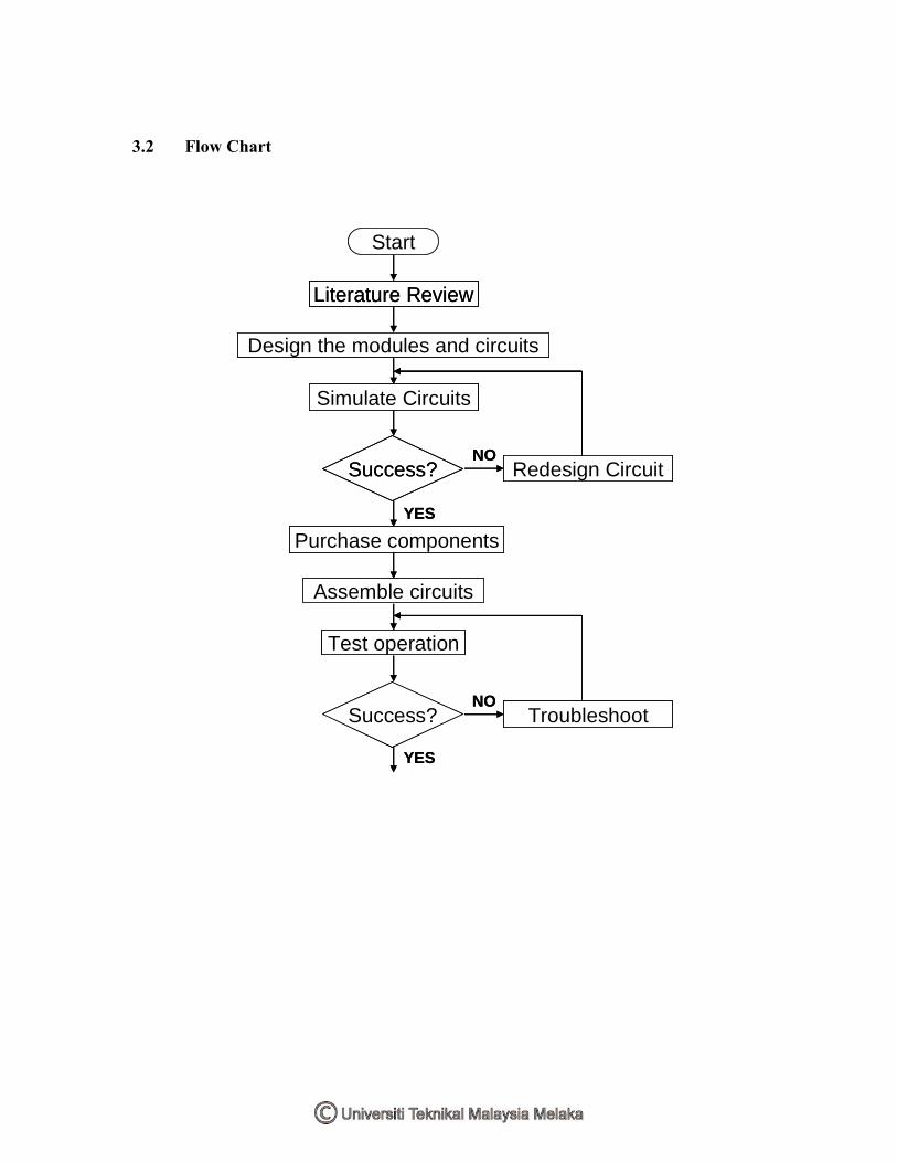
3.2 Flow Chart
Start
Literature Review
Success?
Design the modules and circuits
Simulate Circuits
Redesign Circuit
Troubleshoot
Assemble circuits
Test operation
Success?
Purchase components
YES
YES
NO
NO
Start
Literature Review
Success?
Design the modules and circuits
Simulate Circuits
Redesign Circuit
Troubleshoot
Assemble circuits
Test operation
Success?
Purchase components
YES
YES
NO
NO

End
Assemble the modules
Test operation
Success? Troubleshoot
Analysis
Improvements, modifications & additions
Connect the assembled modules
Test operation
Success? Troubleshoot
Finalize
YES
YES
NO
NO
End
Assemble the modules
Test operation
Success? Troubleshoot
Analysis
Improvements, modifications & additions
Connect the assembled modules
Test operation
Success? Troubleshoot
Finalize
YES
YES
NO
NO
Figure 3.2: Project flow chart

3.3 Gantt Chart
Finalize & completion
Test & troubleshoot
Connect the assembled modules
Analysis
Improvements, modifications & additions
Test & troubleshoot
Assemble modules
Test & troubleshoot
Assemble circuit
Purchase components needed
Simulate circuits using simulation software
Design the modules & circuits
Literature review & research
JMAMFJDNOSAJJAktiviti Projek
Project’s Activities
20082007
Senaraikan aktiviti-aktiviti utama bagi projek yang dicadangkan. Nyatakan jangka masa yang diperlukan bagi setiap
aktiviti.
List major activities involved in the proposed project. Indicate duration of each activity to the related month(s).
PERANCANGAN PROJEK
PROJECT PLANNING
Figure 3.3: Gantt Chart

CHAPTER 4
PROJECT BACKGROUND
4.1 Introduction
4.1.1 Smart Home
What is a Smart Home? A Smart Home is an integration of various systems at
home such as security, home automation, lighting control, CCTV and entertainment
system which is coordinated by a smart home controller and controlled by users using
various centralized command interfaces such as touch screens, keypads, universal remote
controllers, internet browser, telephone and LCD TV screen.

Figure 4.1(a): A smart home system
4.1.1.1 Functions of smart home system
The functions and details of a smart home system based on Figure 3.1(a):
Motion Detection – serves a dual purpose for security for intrusion and
automatic lighting.
Pool & Spa – controls filters, timers, heating temperatures and solar control.
Vehicle Detection – Announces visitors, turn on lights, and switch on TV to
view driveway, etc.
Lighting & Appliances – Automatic lighting and appliances control to
simulate ―lived-in‖ look to deter burglary. Also capable of one touch button to
create optimum scene for movie time, dining, romantic scene & etc.
Irrigation – control and automate irrigation for lawn sprinklers, plus inputs for
rain sensing.
Surveillance Camera – To safeguard compound of the house. Capable of
internet surveillance, automatic video recording & notification via email, etc.
Enhanced Entertainment – Coordinate multiple AV system to bring the best of
entertainment.
Environment Control – Control indoor & outdoor temperature and humidity
level to create the most comfortable environment for indoor & outdoor living.
Front Line Security Layer – Using invisible photobeam sensors & radar type
motion sensor to safeguard the perimeter of the house.
Communication – Control the whole house via any phone at home or away.
Get a call to advise on security, temperature and more.
Internet & Home Networking HAI Weblink II allows the occupant to control
and see status of the house from anywhere via the Internet browser or PDA.
4.1.1.2 Benefits of smart home system
The benefits of a Smart Home are its ―convenience at your finger tip‖ and it’s
comfortable and fun. The down stair living lights can be automatically turned on, turn on
the perimeter lights, draw the curtains, and arm security to night mode with just one
touch button from the comfort of the bedroom. The system can create the perfect mood
for relaxation, movie, party night, romantic dinner or even easy listening with just one
touch of a button.
4.2 Project Background
4.2.1 Indoor Lighting
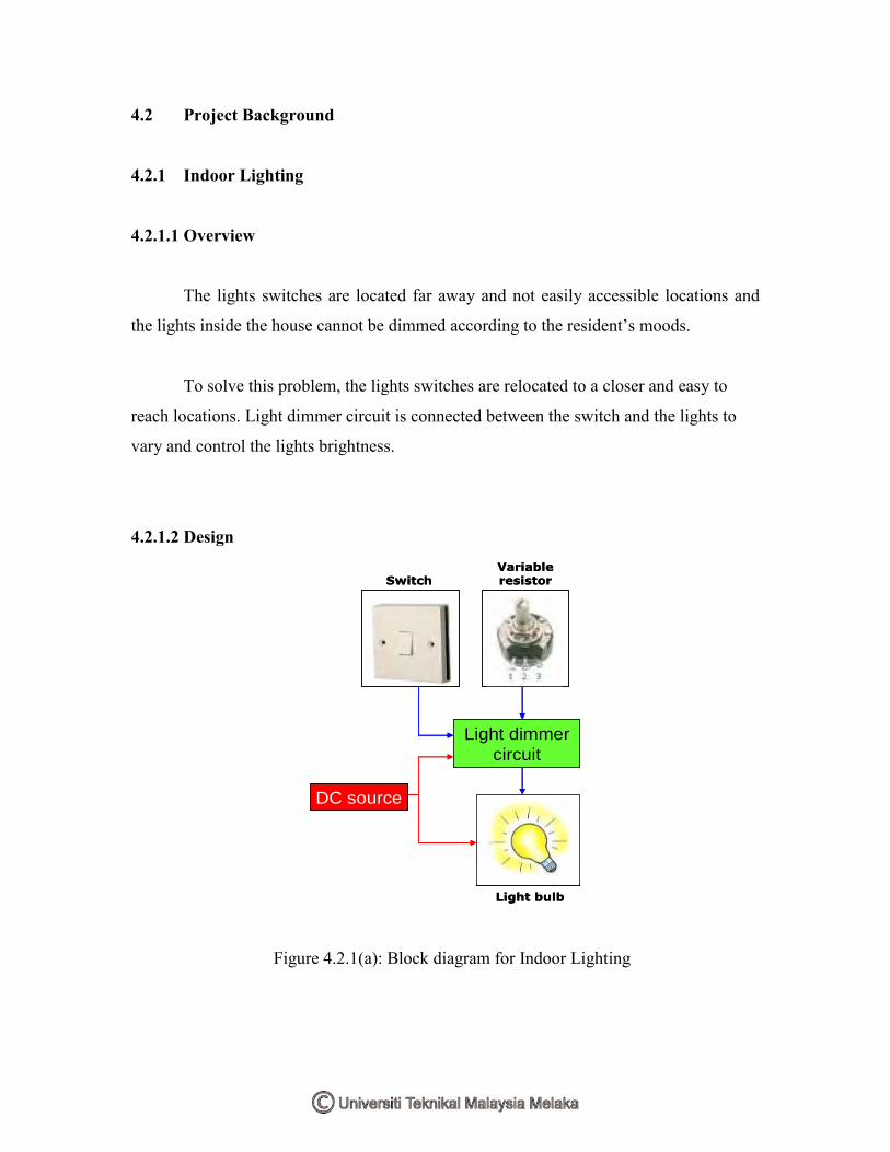
4.2.1.1 Overview
The lights switches are located far away and not easily accessible locations and
the lights inside the house cannot be dimmed according to the resident’s moods.
To solve this problem, the lights switches are relocated to a closer and easy to
reach locations. Light dimmer circuit is connected between the switch and the lights to
vary and control the lights brightness.
4.2.1.2 Design
DC source
Light dimmer
circuit
Light bulb
Variable resistorSwitch
DC source
Light dimmer
circuit
Light bulb
Variable resistorSwitch
Figure 4.2.1(a): Block diagram for Indoor Lighting

A pulse width modulator (PWM) is a device that may be used as an efficient light
dimmer or DC motor speed controller. A PWM circuit works by making a square wave
with a variable on-to-off ratio, the average on time may be varied from 0 to 100 percent.
In this manner, a variable amount of power is transferred to the load. The main advantage
of a PWM circuit over a resistive power controller is the efficiency, at a 50% level, the
PWM will use about 50% of full power, almost all of which is transferred to the load, a
resistive controller at 50% load power would consume about 71% of full power, 50% of
the power goes to the load and the other 21% is wasted heating the series resistor. Load
efficiency is almost always a critical factor in solar powered and other alternative energy
systems.
The additional advantage of pulse width modulation is that the pulses reach the
full supply voltage and will produce more torque in a motor by being able to overcome
the internal motor resistances more easily. Finally, in a PWM circuit, common small
potentiometers may be used to control a wide variety of loads whereas large and
expensive high power variable resistors are needed for resistive controllers.
The main disadvantages of PWM circuits are the added complexity and the
possibility of generating radio frequency interference (RFI). RFI may be minimized by
locating the controller near the load, using short leads, and in some cases, using
additional filtering on the power supply leads.
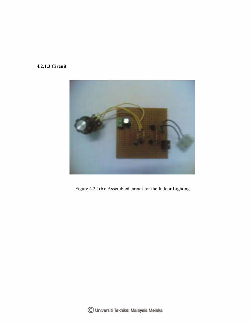
4.2.1.3 Circuit
Figure 4.2.1(b): Assembled circuit for the Indoor Lighting

Figure 4.2.1(c): Light dimmer circuit using PWM control method
The PWM circuit requires a steadily running oscillator to operate. The transistors
C945 provides an oscillating frequency of 150-450 MHz. Resistors R2 and R5 are used to
set the end points of the R6 control, the values shown allow the control to have a full on
and a full off setting within the travel of the potentiometer. These part values may be
varied to change the behavior of the potentiometer. Q1 is the power switch, it receives the
modulated pulse width voltage on the gate terminal and switches the load current on and
off through the Source-Drain current path. When Q1 is on, it provides a ground path for
the load, when Q1 is off, the load's ground is floating. Diode D1 is a flywheel diode that
shorts out the reverse voltage kick from inductive motor loads.
4.2.1.4 Hardware and software
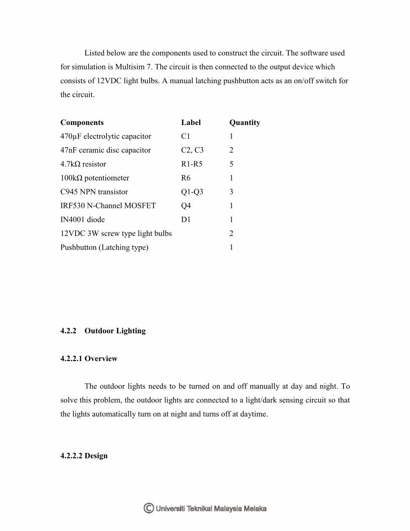
Listed below are the components used to construct the circuit. The software used
for simulation is Multisim 7. The circuit is then connected to the output device which
consists of 12VDC light bulbs. A manual latching pushbutton acts as an on/off switch for
the circuit.
Components Label Quantity
470µF electrolytic capacitor C1 1
47nF ceramic disc capacitor C2, C3 2
4.7kΩ resistor R1-R5 5
100kΩ potentiometer R6 1
C945 NPN transistor Q1-Q3 3
IRF530 N-Channel MOSFET Q4 1
IN4001 diode D1 1
12VDC 3W screw type light bulbs 2
Pushbutton (Latching type) 1
4.2.2 Outdoor Lighting
4.2.2.1 Overview
The outdoor lights needs to be turned on and off manually at day and night. To
solve this problem, the outdoor lights are connected to a light/dark sensing circuit so that
the lights automatically turn on at night and turns off at daytime.
4.2.2.2 Design

DC source
Light/dark sensing
circuit
Light Dependant Resistor (LDR)
Light bulb
Switch
Light
DC source
Light/dark sensing
circuit
Light Dependant Resistor (LDR)
Light bulb
Switch
LightLight
Figure 4.2.2(a): Block diagram for Outdoor Lighting
This module is used to illuminate the outdoor areas of the house automatically.
This is made possible by using a light/dark sensing circuit. The circuit uses a regular
Cadmium-Sulphide Light Dependant Resistor (LDR) which is a variable resistor whose
value decreases with increasing incident light intensity. This circuit is used to sense the
absence of light and produces an output to energize the relay coils. This will close the
contacts and activates the lights where it is connected.
4.2.2.3 Circuit

Figure 4.2.2(b): Assembled circuit for the Outdoor Lighting
Figure 4.2.2(c): IC 555 Timer pin allocations
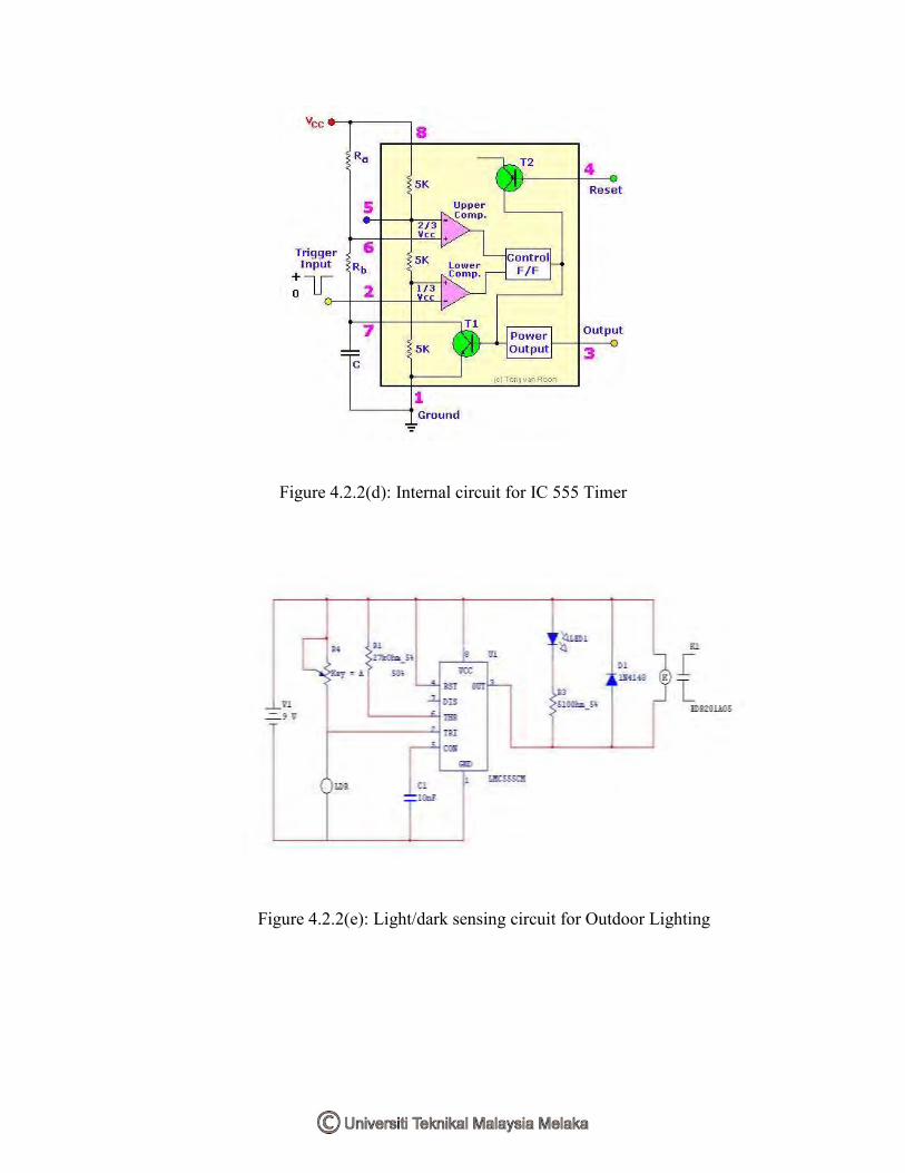
Figure 4.2.2(d): Internal circuit for IC 555 Timer
Figure 4.2.2(e): Light/dark sensing circuit for Outdoor Lighting

Pin 1 is connected to ground and Pin 8 is connected to the voltage source of 9V.
Pin 2 is the input for lower comparator and is used to set the latch, which in turn causes
the output to go high. The LDR and the potentiometer are connected to this pin to provide
the ―turn on‖ signal. Pin 3 is the output which turns on the LED and energizes the relay
coil. Pin 4 is used to reset the latch and return the output to low state. Pin 5 is the control
voltage which provides the reference level for the upper comparator. It is bypassed to
ground for noise immunity using a 10nF capacitor. Pin 6 is one input to the upper
comparator and is used to reset the latch which causes the output to go low.
In bright light the resistance of the LDR can be as low as 80 ohm and at 50lux
(darkness) the resistance increases to over 1 M. The 1M potentiometer control should
provide a wide range for light intensities, if not its value may be increased. The timer
senses the voltage difference between pins 2 and 6. The control R4 is adjusted so that the
relay is off.
When light falls, the resistance of the LDR increases and the difference in input
voltage is compared by the timer, the output will swing towards full supply and drives the
LED and 5V relay.

4.2.2.4 Hardware and software
Listed below are the components used to construct the circuit. The software used
for simulation is Multisim 7. The output from the relay is connected to 9VDC light bulbs.
The module can be activated automatically using the LDR sensing or manually using a
pushbutton.
A 2-way switch provides selection for auto/manual function. The LED indicates
that the circuit is operational and the potentiometer provides calibration for the circuit’s
sensitivity according to the LDR’s location.
Components Label Quantity
Timer LM555 1
1MΩ potentiometer R4 1
27kΩ resistor R1 1
510Ω resistor R3 1
10nF ceramic disc capacitor C1 1
Light Emitting Diode LED 1 1
Light Dependant Resistor LDR 1
IN4148 diode D1 1
5V Relay K1 1
9VDC 3W screw type light bulbs 3
Screw type sockets 3
Pushbutton (latching type) 1
2-way selector switch 1

4.2.3 Indoor Ventilation
4.2.3.1 Overview
The indoor temperature is high during a hot day causing the resident to feel
uncomfortable and sweaty. The warm air is trapped inside the house due to poor indoor
ventilation. To solve this problem, an air circulatory system consists of intake & exhaust
fans is connected to improve the indoor ventilation. These fans are controlled using
temperature sensing circuit.
4.2.3.2 Design
Heat
DC source
Temperature sensing
circuitThermistor
Switch
HeatHeat
DC source
Temperature sensing
circuitThermistorThermistor
Switch

Figure 4.2.3(a): Block diagram for Indoor Ventilation
Temperature measurement is the most common application for NTC thermistors.
The high sensitivity of thermistors and the ability to manufacture components with tightly
controlled temperature accuracy has made the NTC thermistor an ideal device for low
cost temperature measurement.
Figure 4.2.3(b): Wheatstone Bridge
The method of utilizing a thermistor to measure temperature is to use a
Wheatstone bridge with the thermistor as one leg of the bridge. The circuit is one
example of a circuit that utilizes a thermistor to sense temperature. As temperature
increases, the voltage output increases. The selection of R1, R2 and R3 will determine the

sensitivity of the circuit as well as the temperature range for which the circuit is best
suited.
The ventilation fans will be activated when the temperature of the house rises
above a pre-determined level. For this case we take a nominal room temperature of 27C.
When the temperature increases beyond this value, the circuit will activate the relay
which activates the ventilation fans located on the above of the house. The ventilation fan
purpose is to maintain and lower down the rooms temperature by extracting in the cool
air from the outside (intake fan) and discharges the hot air (exhaust fan) from inside the
house. When the temperature returns to its nominal value, the ventilation fans stops and
returns to its idle state. This value can be changed according to the user preference.
4.2.3.3 Circuit
Figure 4.2.3(c): Assembled circuit for Indoor Ventilation
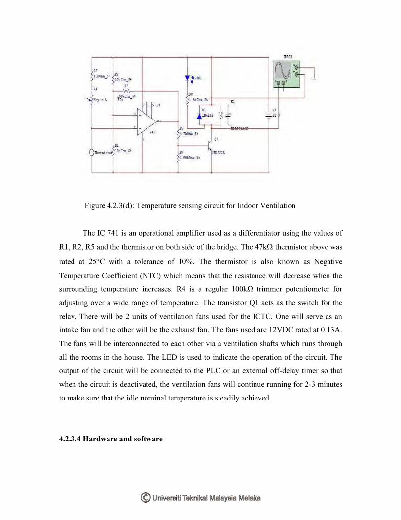
Figure 4.2.3(d): Temperature sensing circuit for Indoor Ventilation
The IC 741 is an operational amplifier used as a differentiator using the values of
R1, R2, R5 and the thermistor on both side of the bridge. The 47k thermistor above was
rated at 25C with a tolerance of 10%. The thermistor is also known as Negative
Temperature Coefficient (NTC) which means that the resistance will decrease when the
surrounding temperature increases. R4 is a regular 100kΩ trimmer potentiometer for
adjusting over a wide range of temperature. The transistor Q1 acts as the switch for the
relay. There will be 2 units of ventilation fans used for the ICTC. One will serve as an
intake fan and the other will be the exhaust fan. The fans used are 12VDC rated at 0.13A.
The fans will be interconnected to each other via a ventilation shafts which runs through
all the rooms in the house. The LED is used to indicate the operation of the circuit. The
output of the circuit will be connected to the PLC or an external off-delay timer so that
when the circuit is deactivated, the ventilation fans will continue running for 2-3 minutes
to make sure that the idle nominal temperature is steadily achieved.
4.2.3.4 Hardware and software

Listed below are the components used to construct the circuit. The software used
for simulation is Multisim 7. The output of the relay is connected to a 12VDC fan taken
from a CPU cooler. The module can be activated automatically using the thermistor
sensing or manually using a pushbutton. A 2-way switch provides selection for
auto/manual function. The LED indicates that the circuit is operational and the
potentiometer provides calibration for the circuit’s sensitivity according to the
thermistor’s location. An independent temperature display unit provides the user with the
current ambient temperature inside the house.
Figure 4.2.3(e): 12VDC CPU fan rated at 0.13A
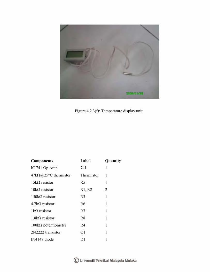
Figure 4.2.3(f): Temperature display unit
Components Label Quantity
IC 741 Op Amp 741 1
47k@25C thermistor Thermistor 1
15kΩ resistor R5 1
10kΩ resistor R1, R2 2
150kΩ resistor R3 1
4.7kΩ resistor R6 1
1kΩ resistor R7 1
1.8kΩ resistor R8 1
100kΩ potentiometer R4 1
2N2222 transistor Q1 1
IN4148 diode D1 1

5V Relay K1 1
Pushbutton (latching type) 1
2-way selector switch 1
12VDC 0.13A CPU fan 1
Temperature display unit 1
4.2.4 Garbage disposal
4.2.4.1 Overview
The residents sometimes missed the garbage collection time. The garbage spilled
when bringing it outside the house and the odor from the garbage attracts flies & brings
unwanted disease. To solve this problem, the PLC manages the disposal according to
time. A garbage route runs in the underground level of the house and a ventilation system
handles the unpleasing odor.
4.2.4.2 Design

AC Synchronous
Motor
AC Source
Push button (Manual)
Push button (Auto)
DC Source
Proximity sensor
AC Synchronous
Motor
AC SourceAC Source
Push button (Manual)
Push button (Auto)
DC SourceDC Source
Proximity sensor
Figure 4.2.4(a): Block diagram for garbage disposal
Full garbage
container
Emptied/Empty garbage
container
Kitchen areaRoad Outside area
Figure 4.2.4(b): Concept diagram for garbage disposal

To create the rotating platform at the underground level, there are two important
parameters that need to be controlled, which is the motor’s speed and direction. The
motor speed needs to be maintained at an optimal speed so that the load is not moving to
fast or else it will spill on the platform.
The motor moves in a single direction since the platform rotates in a single
direction. Even if the motor rotates in the opposite direction (which happened
sometimes), there is no problem as long as the 180 degrees rotation is achieved. The
motor speed is rated at 5-6 rpm which is suitable enough to provide the rotating
functions.
The platform can be rotated automatically or manually according to the situation.
The automatic function is achieved using the latching function from the PLC while the
manual function is achieved using a manual bypass connection over the PLC relay
output. Both functions is activated using pushbuttons.
4.2.4.3 Circuit
There is no circuit used for this module as the module fully utilizes the function of
the PLC and the combination of input and output devices.
4.2.4.4 Hardware and software
The input devices for this module include, non-latching pushbuttons and a PNP
type inductive proximity sensor used to detect when the platform is in its idle position
(180 degrees). The sensor has an optimal sensing range of 5mm and a maximum sensing
range of 8mm.
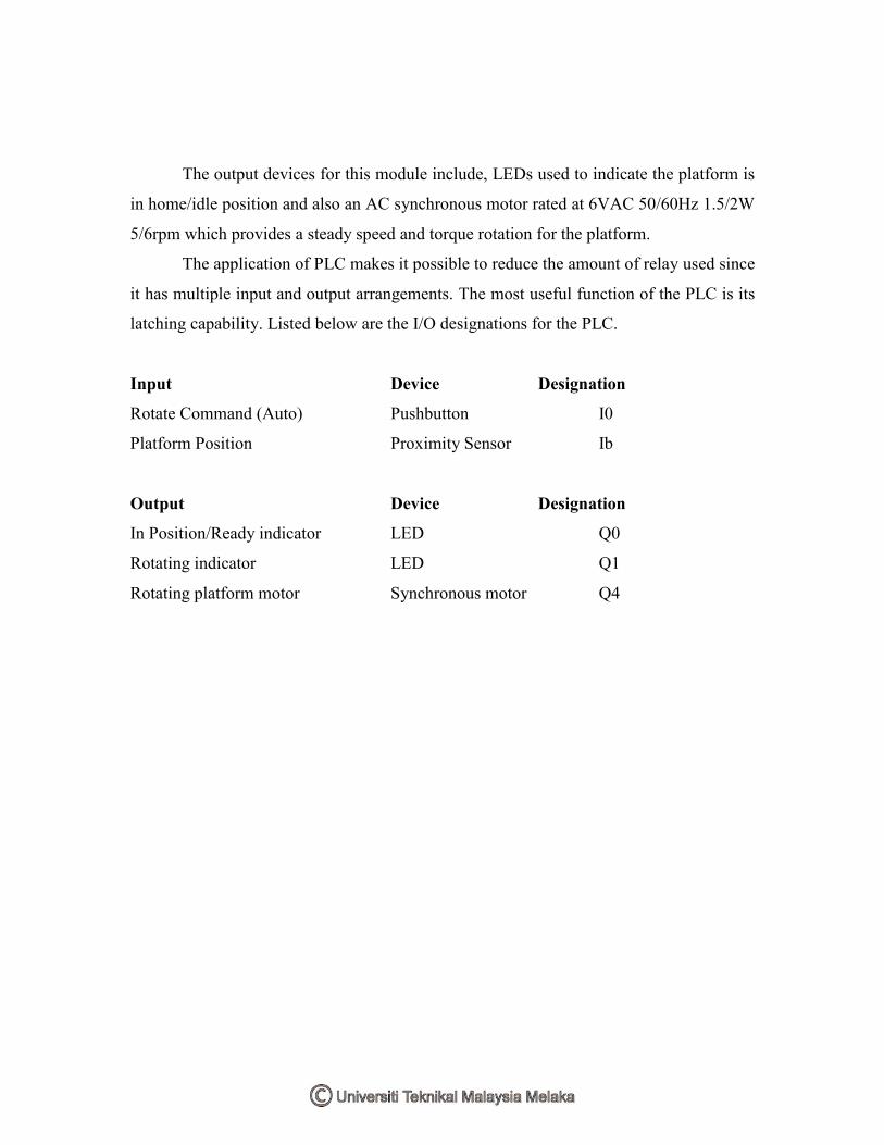
The output devices for this module include, LEDs used to indicate the platform is
in home/idle position and also an AC synchronous motor rated at 6VAC 50/60Hz 1.5/2W
5/6rpm which provides a steady speed and torque rotation for the platform.
The application of PLC makes it possible to reduce the amount of relay used since
it has multiple input and output arrangements. The most useful function of the PLC is its
latching capability. Listed below are the I/O designations for the PLC.
Input Device Designation
Rotate Command (Auto) Pushbutton I0
Platform Position Proximity Sensor Ib
Output Device Designation
In Position/Ready indicator LED Q0
Rotating indicator LED Q1
Rotating platform motor Synchronous motor Q4

Figure 4.2.4(c): Ladder diagram for overall Garbage Disposal module
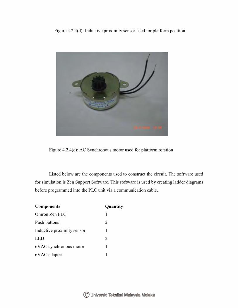
Figure 4.2.4(d): Inductive proximity sensor used for platform position
Figure 4.2.4(e): AC Synchronous motor used for platform rotation
Listed below are the components used to construct the circuit. The software used
for simulation is Zen Support Software. This software is used by creating ladder diagrams
before programmed into the PLC unit via a communication cable.
Components Quantity
Omron Zen PLC 1
Push buttons 2
Inductive proximity sensor 1
LED 2
6VAC synchronous motor 1
6VAC adapter 1
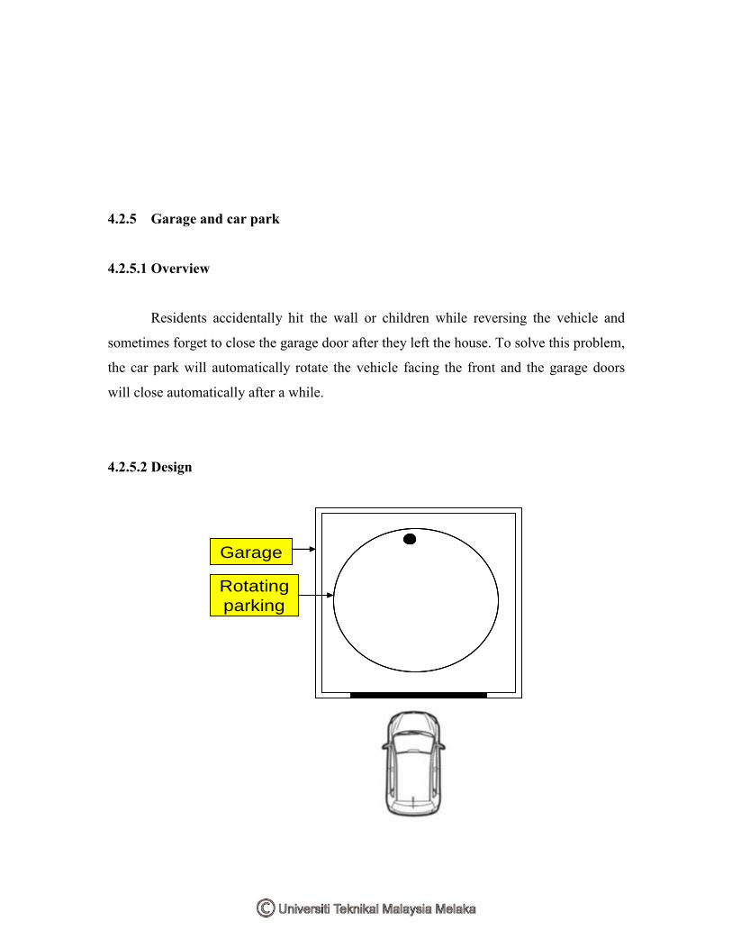
4.2.5 Garage and car park
4.2.5.1 Overview
Residents accidentally hit the wall or children while reversing the vehicle and
sometimes forget to close the garage door after they left the house. To solve this problem,
the car park will automatically rotate the vehicle facing the front and the garage doors
will close automatically after a while.
4.2.5.2 Design
Garage
Rotating
parking
Garage
Rotating
parking
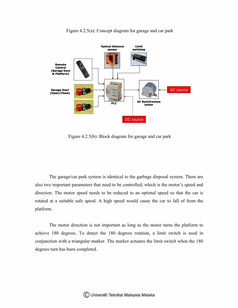
Figure 4.2.5(a): Concept diagram for garage and car park
PLCAC Synchronous
motor
Optical distance sensor
Limit switches
DC source
Garage Door (Open/Close)
AC source
Remote Control
(Garage Door & Platform)
PLCAC Synchronous
motor
Optical distance sensor
Limit switches
DC source
Garage Door (Open/Close)
AC source
Remote Control
(Garage Door & Platform)
Figure 4.2.5(b): Block diagram for garage and car park
The garage/car park system is identical to the garbage disposal system. There are
also two important parameters that need to be controlled, which is the motor’s speed and
direction. The motor speed needs to be reduced to an optimal speed so that the car is
rotated at a suitable safe speed. A high speed would cause the car to fall of from the
platform.
The motor direction is not important as long as the motor turns the platform to
achieve 180 degrees. To detect the 180 degrees rotation, a limit switch is used in
conjunction with a triangular marker. The marker actuates the limit switch when the 180
degrees turn has been completed.

Figure 4.2.5(c): Limit switch and triangular marker
Figure 4.2.5(d): Rotating platform
The garage and car park system operates using many sensors and switches. The
optical distance sensor is used to detect when the car is in position to enter the garage.
The garage door opens and actuates the maximum door limit switch which activates a 10
second timer. Within the allocated time, the vehicle must enter the garage and the garage
door automatically closes.
When the vehicle wishes to leave the garage, the user can open the garage door
manually (by pressing the open door pushbutton) or by pressing the ―unlock‖ button on
the remote control.
4.2.5.3 Circuit
There is no circuit used for this module as the module fully utilizes the function of
the PLC and the combination of input and output devices.
4.2.5.4 Hardware and software
The input devices for this module include, non-latching pushbuttons, PNP type
optical distance sensor used to detect when the car is in entry position and limit switches
The optical distance sensor is programmable to suite any range within 0.2 meters and up
to 10 meters. The limit switches is used to detect the platform position and also to detect
the garage door position.

Figure 4.2.5(e): Optical distance sensor
The output devices for this module include, LEDs used to indicate the platform is
in home/idle position or rotating, an AC synchronous motor rated at 6VAC 50/60Hz
1.5/2W 5/6rpm which provides a steady speed and torque rotation for the platform and
also 12VDC light bulbs to indicate the garage door coil is open or close.
The application of PLC makes it possible to reduce the amount of relay used since
it has multiple input and output arrangements. The most useful function of the PLC is its
latching capability. Listed below are the I/O designations for the PLC.

Input Device Designation
Rotate command (Auto) Pushbutton I1
Reset/Stop rotate Pushbutton I2
Maximum door position Limit switch I4
Minimum door position Limit switch I5
Rotate command (Remote) Remote I6
Platform position Limit switch I7
Open door command Pushbutton/Remote I8
Close door command Pushbutton/Remote I9
Close door command (Delayed) Optical distance sensor Ia
Output Device Designation
In Position/Ready indicator LED Q2
Rotating indicator LED Q3
Rotating platform motor Synchronous motor Q5
Open garage door coil 12VDC light bulb Q6
Close garage door coil 12VDC light bulb Q7

Figure 4.2.5(f): Ladder diagram for garage door
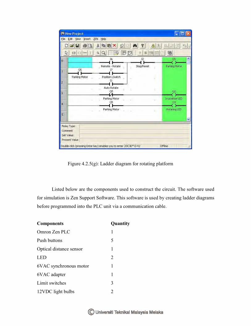
Figure 4.2.5(g): Ladder diagram for rotating platform
Listed below are the components used to construct the circuit. The software used
for simulation is Zen Support Software. This software is used by creating ladder diagrams
before programmed into the PLC unit via a communication cable.
Components Quantity
Omron Zen PLC 1
Push buttons 5
Optical distance sensor 1
LED 2
6VAC synchronous motor 1
6VAC adapter 1
Limit switches 3
12VDC light bulbs 2

Light bulbs socket 2
4.2.6 Events alert
4.2.6.1 Overview
Normal house does not have fire and flood detection system to alert the occupants
of danger and disaster. To fix this problem, a heat & smoke sensor is added for fire
detection and a water level sensor is added for flood detection.
4.2.6.2 Design
Smoke
Buzzer control
circuit
Smoke sensing
circuit
Heat sensing
circuit
Water level
sensor
Fire detection
DC
source
Flood detection
Thermistor
Light Dependent Resistor (LDR)
Light Emitting Diode (LED)
Piezo buzzer
Smoke
Buzzer control
circuit
Smoke sensing
circuit
Heat sensing
circuit
Water level
sensor
Fire detection
DC
source
Flood detection
ThermistorThermistor
Light Dependent Resistor (LDR)
Light Emitting Diode (LED)
Piezo buzzer
Figure 4.2.6(a): Block diagram for Events Alert
This module combines 4 circuit to create a house event alert module. The heat
sensing circuit and smoke sensing circuit combines together to create the fire detection
system. The heat circuit is similar as the ones used for the indoor ventilation module. The
difference lies in its activation threshold which detects a higher temperature before it
activates the buzzer circuit. The smoke sensor detects smoke produced from the fire.
The water level sensor acts as the flood detector which monitors water level in
drainage. The buzzer control circuit is used to vary the interval between beeps as user’s
reference.
4.2.6.3 Circuit
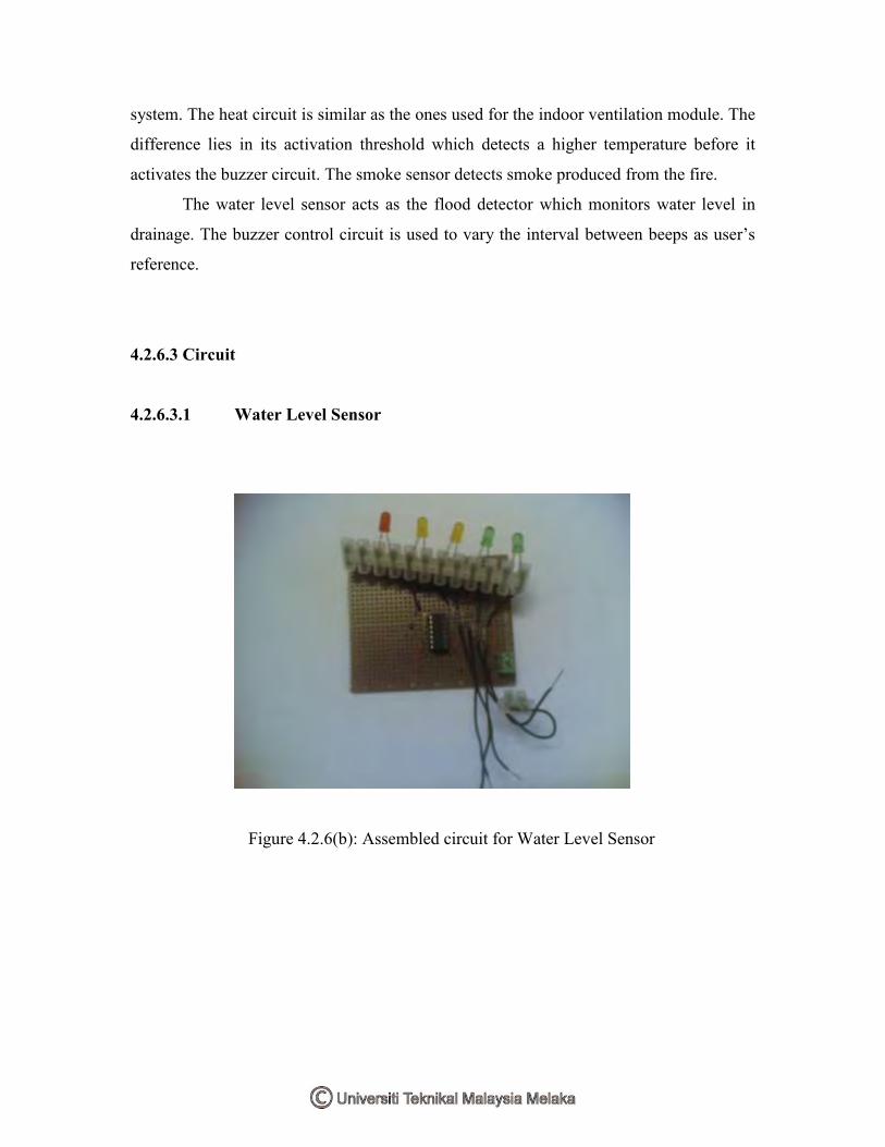
4.2.6.3.1 Water Level Sensor
Figure 4.2.6(b): Assembled circuit for Water Level Sensor

Figure 4.2.6(c): Water Level Sensor circuit for Events Alert
This circuit indicates the water level and produces an alarm when the high level is
reached. The circuit uses a pair of AND gates from the CMOS 4081 operating on logic
inputs (0 or 1) to indicate the water level through LEDs. When the water is empty the
wires in the tank are open circuited and this pulls the switch low hence opening the
switch and LEDs are OFF. As the water starts filling up, first the wire in the tank
connected to J1 and the + supply are shorted by water. This turns the LED 2 on. As the
water level continues to rise, the LED 3, 1 and 4 lights up gradually. As the inputs are
HIGH, this causes LED 5 to turn on and the relay is activated.

4.2.6.3.2 Heat Sensing
Figure 4.2.6(d): Assembled circuit for Heat Sensing
Figure 4.2.6(e): Heat Sensing circuit for Events Alert
The IC 741 is an operational amplifier used as a differentiator using the values of
R1, R2, R5 and the thermistor on both side of the bridge.The 47k thermistor above was
rated at 33C with a tolerance of 10%. The thermistor is also known as Negative
Temperature Coefficient (NTC) which means that the resistance will decrease when the
surrounding temperature increases. R4 is a regular 1MΩ trimmer potentiometer for
adjusting over a wide range of temperature. The transistor Q1 acts as the switch for the
relay. The LED is used to indicate the operation of the circuit. The output of the circuit is
connected to the buzzer interval circuit and the buzzer will sound when a heat from fire is
detected.
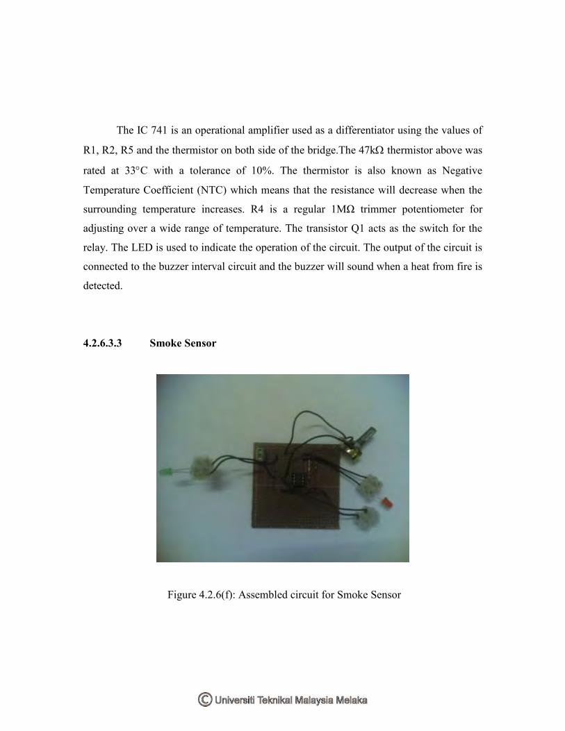
4.2.6.3.3 Smoke Sensor
Figure 4.2.6(f): Assembled circuit for Smoke Sensor

Figure 4.2.6(g): Smoke Sensor circuit for Events Alert
This circuit is similar as the light/dark sensing circuit for the Outdoor Lighting
module with some modifications to allow it to function as a smoke detector. A LED or
any suitable light source is placed in parallel with the Light Dependant Resistor (LDR).
When a fire occurs, the smoke will fill the gap between the LED 2 and the LDR. The
amount of light falling on the LDR decreases and the resistance of the LDR increases
thus activating the relay.
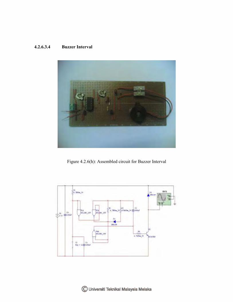
4.2.6.3.4 Buzzer Interval
Figure 4.2.6(h): Assembled circuit for Buzzer Interval

Figure 4.2.6(i): Buzzer Interval circuit for Events Alert
While J1 remains open, the circuit uses virtually no current. When the switch is
closed, the buzzer produces a series of beeps at a certain intervals. R3 & C2 sets the
length of beeps while R4 & C2 sets the delay between the beeps. If the initial values are
doubled, then the interval would double as well. Gates 5 & 6 of the CMOS 4011 is not
used in the circuit. When the oscillator is running, pin 10 keeps switching back and forth
between high to low. Pin 11 supplies base current to Q1 - through R4. As pin 10 switches
on and off - the transistor switches on and off. While the transistor is on - it connects the
negative lead of the Buzzer to ground - and the Buzzer sounds. To keep the standby
current low - the value of 4.7MΩ was chosen for R1 and the current through R1 is
flowing to ground through the switch. This means that Pin 1 & 2 is low - and C1 is
discharged. And while pin 10 remains low, the Buzzer is silent.
4.2.6.4 Hardware and software
Listed below are the components used to construct the circuit. The software used
for simulation is Multisim 7.
Water Level Sensor
Components Label Quantity
CMOS 4081 Quad AND gates 4081 1
680Ω resistor R1-R4 4
280Ω resistor R5 1
Light Emitting Diode LED1-5 5
5V Relay K1 1

Heat Sensing
Components Label Quantity
IC 741 Op Amp 741 1
33k@25C thermistor Thermistor 1
15kΩ resistor R5 1
10kΩ resistor R1, R2 2
150kΩ resistor R3 1
4.7kΩ resistor R6 1
1kΩ resistor R7 1
1.8kΩ resistor R8 1
100kΩ potentiometer R4 1
2N2222 transistor Q1 1
Light Emitting diode LED 1 1
IN4148 diode D1 1
5V Relay K1 1
Smoke Sensor
Components Label Quantity
555 Timer LM555 1
1MΩ potentiometer R4 1
27kΩ resistor R1 1
510Ω resistor R2, R3 2
10nF ceramic disc capacitor C1 1

Light Emitting Diode LED 1, 2 2
Light Dependant Resistor LDR 1
IN4148 diode D1 1
5V Relay K1 1
Buzzer Interval
Components Label Quantity
CMOS 4011 Quad NAND gates 4011 1
680nF ceramic disc capacitor C2 1
100nF ceramic disc capacitor C1, C3 2
4.7MΩ resistor R1, R2 2
470kΩ resistor R3 1
4.7kΩ resistor R4 1
IN4148 diode D1, D2 2
BC547 NPN transistor Q1 1

4.2.7 Garden Management
4.2.7.1 Overview
The plant in the garden dies due to lack of watering and the gardens are infected
by pests. PLC manages the garden’s water sprinkler and the garden is equipped with
ultrasonic pest repellant to ward of the pests.
4.2.7.2 Design
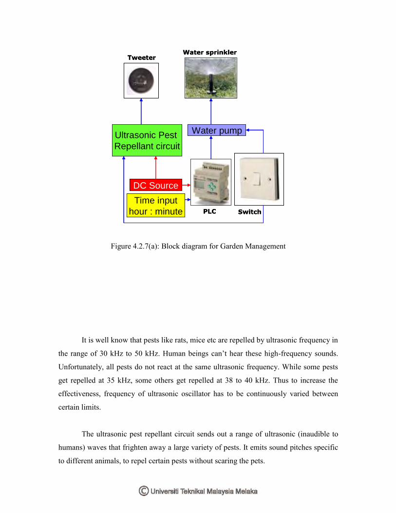
Water sprinkler
Ultrasonic Pest
Repellant circuit
DC Source
PLC
Water pump
Tweeter
Switch
Time input
hour : minute
Water sprinkler
Ultrasonic Pest
Repellant circuit
DC Source
PLC
Water pump
Tweeter
Switch
Time input
hour : minute
Figure 4.2.7(a): Block diagram for Garden Management
It is well know that pests like rats, mice etc are repelled by ultrasonic frequency in
the range of 30 kHz to 50 kHz. Human beings can’t hear these high-frequency sounds.
Unfortunately, all pests do not react at the same ultrasonic frequency. While some pests
get repelled at 35 kHz, some others get repelled at 38 to 40 kHz. Thus to increase the
effectiveness, frequency of ultrasonic oscillator has to be continuously varied between
certain limits.
The ultrasonic pest repellant circuit sends out a range of ultrasonic (inaudible to
humans) waves that frighten away a large variety of pests. It emits sound pitches specific
to different animals, to repel certain pests without scaring the pets.

Unlike some pest controls that use dangerous, sometimes poisonous means of
ridding pests, this circuit uses ultrasonic sound frequency that are slightly audible to
humans to scare away animals and insects. It is a humane option to fixing the pest
problem. Say goodbye to rat poison, harmful chemicals or worrying about the children
and pets.
4.2.7.3 Circuit
Figure 4.2.7(b): Ultrasonic pest repellant circuit for Garden Management
The circuit consists of a phase locked loop (CMOS 4047) wired as a 22 KHz
oscillator. The output is amplified by a pair of complimentary output transistors and
drives a piezoelectric tweeter. The current drain is estimated at around 120mA so an
external power supply is required. The frequency is varied using the 4.7kΩ
potentiometer. The piezoelectric tweeter acts as the ultrasonic frequency transmitter.
4.2.7.4 Hardware and software

Listed below are the components used to construct the circuit. The software used
for simulation is Proteus 6.
Components Label Quantity
CMOS 4047 Monostable/Astable Multivibrator 4047 1
4.7kΩ potentiometer RV1 1
4.7nF ceramic disc capacitor C1 1
22nF electrolytic capacitor C2 1
BC337 NPN Epitaxial Silicon Transistor Q1, Q2 2
BC327 PNP Epitaxial Silicon Transistor Q3, Q4 2
Piezoelectric tweeter 1
4.3 Components
4.3.1 Programmable Logic Controller (PLC)
4.3.1.1 Introduction to PLC

A programmable logic controller (PLC), or programmable controller is a digital
computer used for automation of industrial processes, such as control of machinery on
factory assembly lines. Unlike general-purpose computers, the PLC is designed for
multiple inputs and output arrangements, extended temperature ranges, immunity to
electrical noise, and resistance to vibration and impact. Programs to control machine
operation are typically stored in battery-backed or non-volatile memory. A PLC is an
example of a real time system since output results must be produced in response to input
conditions within a bounded time, otherwise unintended operation will result.
Figure 4.3.1(a): PLC and input/output arrangements
4.3.1.2 Features of PLC

Figure 4.3.1(b): Control Panel with PLC
The main difference from other computers is that PLC are armored for severe
condition (dust, moisture, heat, cold, etc) and have the facility for extensive input/output
(I/O) arrangements. These connect the PLC to sensors and actuators. PLCs read limit
switches, analog process variables (such as temperature and pressure), and the positions
of complex positioning systems. Some even use machine vision. On the actuator side,
PLCs operate electric motors, pneumatic or hydraulic cylinders, magnetic relays or
solenoids, or analog outputs. The input/output arrangements may be built into a simple
PLC, or the PLC may have external I/O modules attached to a computer network that
plugs into the PLC.

PLCs were invented as replacements for automated systems that would use
hundreds or thousands of relays, cam timers, and drum sequencers. Often, a single PLC
can be programmed to replace thousands of relays. Programmable controllers were
initially adopted by the automotive manufacturing industry, where software revision
replaced the re-wiring of hard-wired control panels when production models changed.
Many of the earliest PLCs expressed all decision making logic in simple ladder
logic which appeared similar to electrical schematic diagrams. The electricians were quite
able to trace out circuit problems with schematic diagrams using ladder logic. This
program notation was chosen to reduce training demands for the existing technicians.
Other early PLCs used a form of instruction list programming, based on a stack-based
logic solver.
The functionality of the PLC has evolved over the years to include sequential
relay control, motion control, process control, distributed control systems and
networking. The data handling, storage, processing power and communication
capabilities of some modern PLCs are approximately equivalent to desktop computers.
PLC-like programming combined with remote I/O hardware, allow a general-purpose
desktop computer to overlap some PLCs in certain applications. Under the IEC 61131-3
standard, PLCs can be programmed using standards-based programming languages. A
graphical programming notation called Sequential Function Charts is available on certain
programmable controllers.
4.3.1.3 Comparing PLC with other control systems
PLCs are well-adapted to a certain range of automation tasks. These are typically
industrial processes in manufacturing where the cost of developing and maintaining the
automation system is high relative to the total cost of the automation, and where changes
to the system would be expected during its operational life. PLCs contain input and
output devices compatible with industrial pilot devices and controls; little electrical
design is required, and the design problem centers on expressing the desired sequence of

operations in ladder logic (or function chart) notation. PLC applications are typically
highly customized systems so the cost of a packaged PLC is low compared to the cost of
a specific custom-built controller design. On the other hand, in the case of mass-produced
goods, customized control systems are economic due to the lower cost of the
components, which can be optimally chosen instead of a "generic" solution, and where
the non-recurring engineering charges are spread over thousands of sales.
For high volume or very simple fixed automation tasks, different techniques are
used. For example, a consumer dishwasher would be controlled by an electromechanical
cam timer costing only a few dollars in production quantities.
A microcontroller-based design would be appropriate where hundreds or
thousands of units will be produced and so the development cost (design of power
supplies and input/output hardware) can be spread over many sales, and where the end-
user would not need to alter the control. Automotive applications are an example;
millions of units are built each year, and very few end-users alter the programming of
these controllers. However, some specialty vehicles such as transit busses economically
use PLCs instead of custom-designed controls, because the volumes are low and the
development cost would be uneconomic.
Very complex process control, such as used in the chemical industry, may require
algorithms and performance beyond the capability of even high-performance PLCs. Very
high-speed or precision controls may also require customized solutions; for example,
aircraft flight controls.
PLCs may include logic for single-variable feedback analog control loop, a
"proportional, integral, derivative" or "PID controller." A PID loop could be used to
control the temperature of a manufacturing process, for example. Historically PLCs were
usually configured with only a few analog control loops; where processes required
hundreds or thousands of loops, a distributed control system (DCS) would instead be
used. However, as PLCs have become more powerful, the boundary between DCS and
PLC applications has become less clear-cut.

4.3.1.4 Programming
Early PLCs, up to the mid-1980s, were programmed using proprietary
programming panels or special-purpose programming terminals, which often had
dedicated function keys representing the various logical elements of PLC programs.
Programs were stored on cassette tape cartridges. Facilities for printing and
documentation were very minimal due to lack of memory capacity. More recently, PLC
programs are typically written in a special application on a personal computer, then
downloaded by a direct-connection cable or over a network to the PLC. The very oldest
PLCs used non-volatile magnetic core memory but now the program is stored in the PLC
either in battery-backed-up RAM or some other non-volatile flash memory.
Early PLCs were designed to be used by electricians who would learn PLC
programming on the job. These PLCs were programmed in "ladder logic", which strongly
resembles a schematic diagram of relay logic. Modern PLCs can be programmed in a
variety of ways, from ladder logic to more traditional programming languages such as
BASIC and C. Another method is State Logic, a Very High Level Programming
Language designed to program PLCs based on State Transition Diagrams.
Recently, the International standard IEC 61131-3 has become popular. IEC
61131-3 currently defines five programming languages for programmable control
systems: FBD (Function block diagram), LD (Ladder diagram), ST (Structured text,
similar to the Pascal programming language), IL (Instruction list, similar to assembly
language) and SFC (Sequential function chart). These techniques emphasize logical
organization of operations.
While the fundamental concepts of PLC programming are common to all
manufacturers, differences in I/O addressing, memory organization and instruction sets
mean that PLC programs are never perfectly interchangeable between different makers.
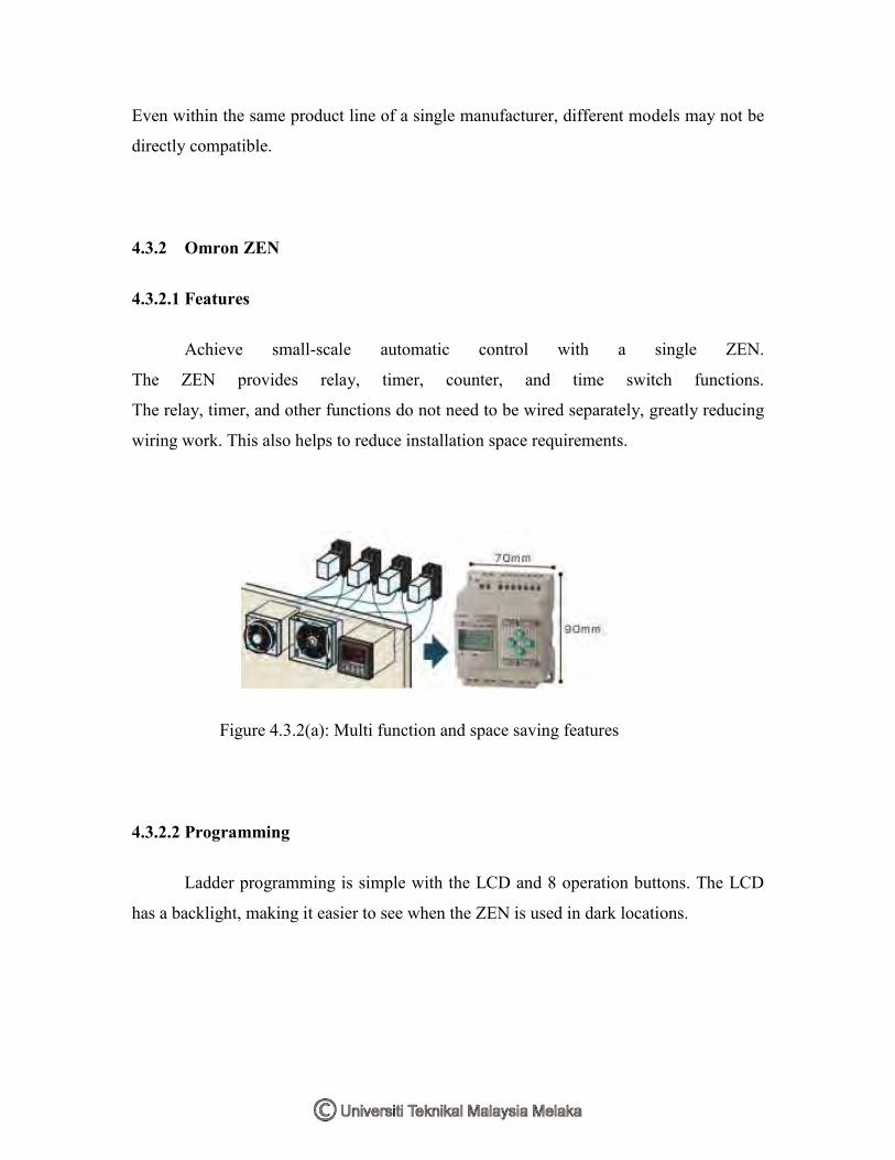
Even within the same product line of a single manufacturer, different models may not be
directly compatible.
4.3.2 Omron ZEN
4.3.2.1 Features
Achieve small-scale automatic control with a single ZEN.
The ZEN provides relay, timer, counter, and time switch functions.
The relay, timer, and other functions do not need to be wired separately, greatly reducing
wiring work. This also helps to reduce installation space requirements.
Figure 4.3.2(a): Multi function and space saving features
4.3.2.2 Programming
Ladder programming is simple with the LCD and 8 operation buttons. The LCD
has a backlight, making it easier to see when the ZEN is used in dark locations.

Figure 4.3.2(b): Programming the Omron ZEN
4.3.2.3 Functions
Flexible power supply voltage between 12 and 24VDC or 100 and 240VAC
Economy CPU Units have been added to the series.
An 8-digit comparator has been added.
Use of a Memory Cassette makes it easy to copy and save programs.
Password function provides security.
Multi-language display in six languages (English, Japanese, German, French,
Spanish, and Italian).
User-set messages can be displayed using the display function.
4.3.2.4 Expansion
Up to three Expansion I/O Units can be easily connected if there are not enough
I/O points. Expansion I/O Units are only 35 mm wide, which helps to save space.

Figure 4.3.2(c): Expansion units
4.3.2.5 Support software
Programs can be easily written and saved using a personal computer. A
simulation function has been added to enable checking program operation on the
computer before wiring.
Figure 4.3.2(d): Support software

4.3.3 Integrated Circuit (IC)
4.3.3.1 Introduction
In electronics, an integrated circuit (also known as IC, microcircuit, microchip,
silicon chip, or chip) is a miniaturized electronic circuit (consisting mainly of
semiconductor devices, as well as passive components) that has been manufactured in the
surface of a thin substrate of semiconductor material.
A hybrid integrated circuit is a miniaturized electronic circuit constructed of
individual semiconductor devices, as well as passive components, bonded to a substrate
or circuit board.
4.3.3.2 History of ICs

Integrated circuits were made possible by experimental discoveries which showed
that semiconductor devices could perform the functions of vacuum tubes, and by mid-
20th-century technology advancements in semiconductor device fabrication. The
integration of large numbers of tiny transistors into a small chip was an enormous
improvement over the manual assembly of circuits using discrete electronic components.
The integrated circuit's mass production capability, reliability, and building-block
approach to circuit design ensured the rapid adoption of standardized ICs in place of
designs using discrete transistors.
Figure 4.3.3: Integrated circuit
4.3.3.3 Advantages of ICs
There are two main advantages of ICs over discrete circuits: cost and
performance. Cost is low because the chips, with all their components, are printed as a
unit by photolithography and not constructed one transistor at a time. Performance is high
since the components switch quickly and consume little power, because the components
are small and close together. As of 2006, chip areas range from a few square mm to
around 350 mm², with up to 1 million transistors per mm².
4.3.3.4 Popularity of ICs

Only a half century after their development was initiated, integrated circuits have
become ubiquitous. Computers, cellular phones, and other digital appliances are now
inextricable parts of the structure of modern societies. That is, modern computing,
communications, manufacturing and transport systems, including the Internet, all depend
on the existence of integrated circuits. Indeed, many scholars believe that the digital
revolution—brought about by the microchip revolution—was one of the most significant
occurrences in the history of humankind.
4.3.3.5 Classifications of ICs
Integrated circuits can be classified into analog, digital and mixed signal (both
analog and digital on the same chip).
Digital integrated circuits can contain anything from a few thousand to millions of
logic gates, flip-flops, multiplexers, and other circuits in a few square millimeters. The
small size of these circuits allows high speed, low power dissipation, and reduced
manufacturing cost compared with board-level integration. These digital ICs, typically
microprocessors, DSPs, and micro controllers work using binary mathematics to process
"one" and "zero" signals.
Analog ICs, such as sensors, power management circuits, and operational
amplifiers, work by processing continuous signals. They perform functions like
amplification, active filtering, demodulation, mixing, etc. Analog ICs ease the burden on
circuit designers by having expertly designed analog circuits available instead of
designing a difficult analog circuit from scratch.
ICs can also combine analog and digital circuits on a single chip to create
functions such as A/D converters and D/A converters. Such circuits offer smaller size and
lower cost, but must carefully account for signal interference
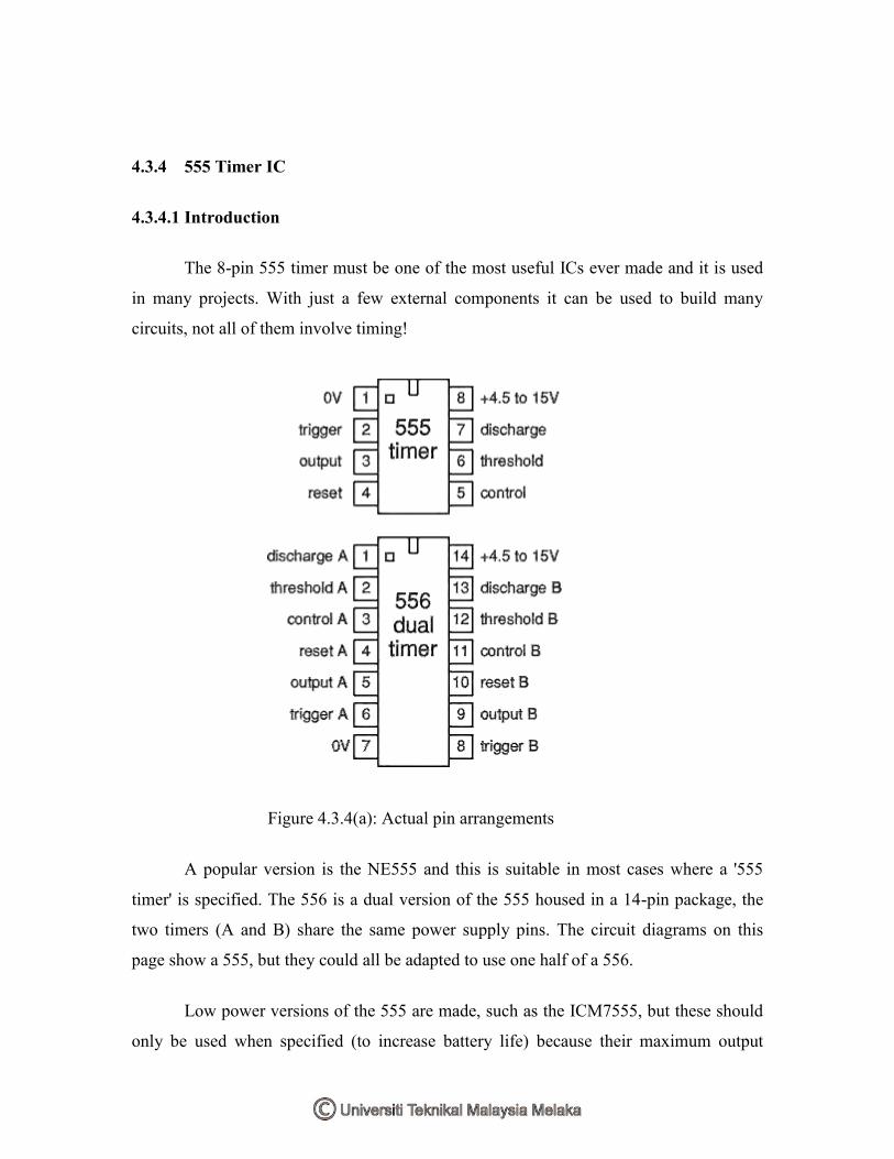
4.3.4 555 Timer IC
4.3.4.1 Introduction
The 8-pin 555 timer must be one of the most useful ICs ever made and it is used
in many projects. With just a few external components it can be used to build many
circuits, not all of them involve timing!
Figure 4.3.4(a): Actual pin arrangements
A popular version is the NE555 and this is suitable in most cases where a '555
timer' is specified. The 556 is a dual version of the 555 housed in a 14-pin package, the
two timers (A and B) share the same power supply pins. The circuit diagrams on this
page show a 555, but they could all be adapted to use one half of a 556.
Low power versions of the 555 are made, such as the ICM7555, but these should
only be used when specified (to increase battery life) because their maximum output

current of about 20mA (with a 9V supply) is too low for many standard 555 circuits. The
ICM7555 has the same pin arrangement as a standard 555.
The circuit symbol for a 555 (and 556) is a box with the pins arranged to suit the
circuit diagram: for example 555 pin 8 at the top for the +Vs supply, 555 pin 3 output on
the right. Usually just the pin numbers are used and they are not labelled with their
function.
The 555 and 556 can be used with a supply voltage (Vs) in the range 4.5 to 15V
(18V absolute maximum).
Standard 555 and 556 ICs create a significant 'glitch' on the supply when their
output changes state. This is rarely a problem in simple circuits with no other ICs, but in
more complex circuits a smoothing capacitor (i.e. 100µF) should be connected across the
+Vs and 0V supply near the 555 or 556.
The input and output pin functions are described briefly below and there are fuller
explanations covering the various circuits:
Astable - producing a square wave
Monostable - producing a single pulse when triggered
Bistable - a simple memory which can be set and reset
Buffer- an inverting buffer (Schmitt trigger)
4.3.4.2 Inputs of 555
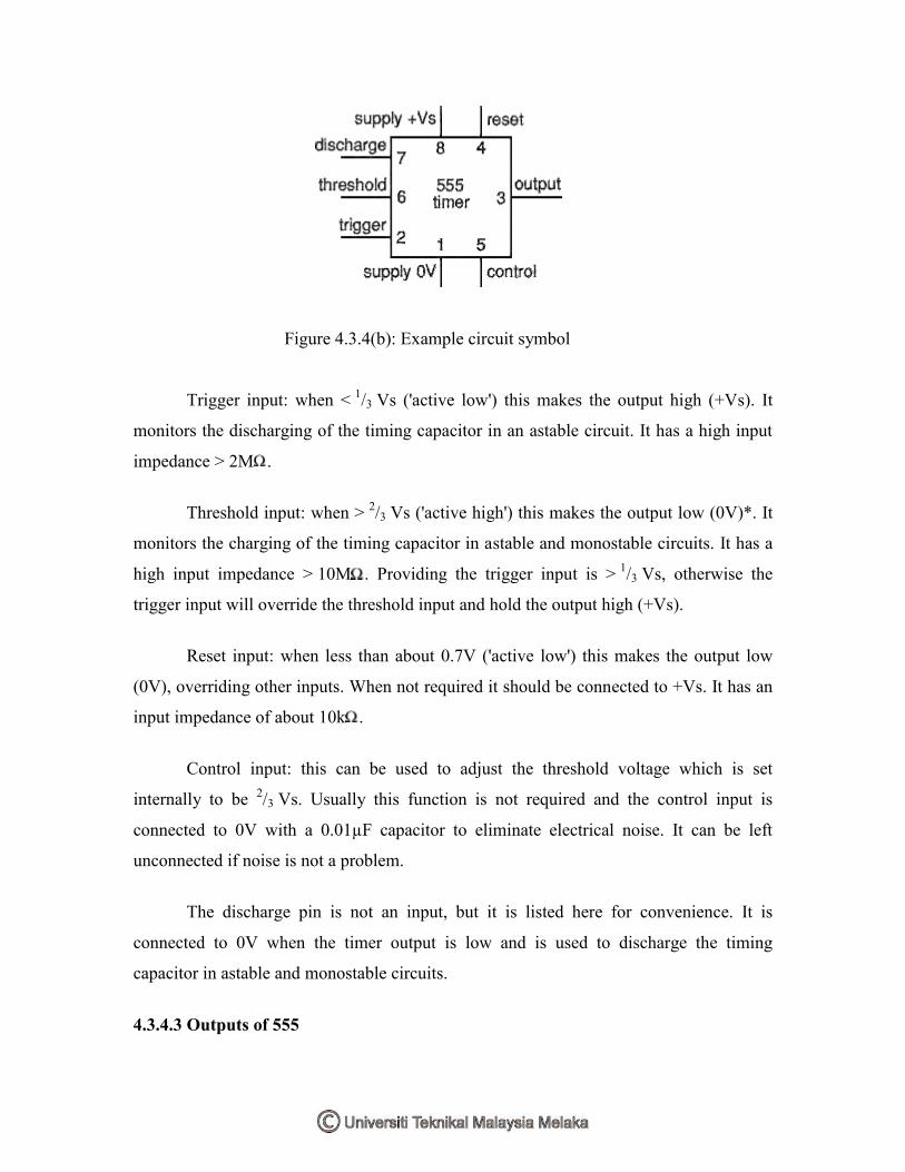
Figure 4.3.4(b): Example circuit symbol
Trigger input: when < 1/3 Vs ('active low') this makes the output high (+Vs). It
monitors the discharging of the timing capacitor in an astable circuit. It has a high input
impedance > 2M .
Threshold input: when > 2/3 Vs ('active high') this makes the output low (0V)*. It
monitors the charging of the timing capacitor in astable and monostable circuits. It has a
high input impedance > 10M . Providing the trigger input is > 1/3 Vs, otherwise the
trigger input will override the threshold input and hold the output high (+Vs).
Reset input: when less than about 0.7V ('active low') this makes the output low
(0V), overriding other inputs. When not required it should be connected to +Vs. It has an
input impedance of about 10k .
Control input: this can be used to adjust the threshold voltage which is set
internally to be 2/3 Vs. Usually this function is not required and the control input is
connected to 0V with a 0.01µF capacitor to eliminate electrical noise. It can be left
unconnected if noise is not a problem.
The discharge pin is not an input, but it is listed here for convenience. It is
connected to 0V when the timer output is low and is used to discharge the timing
capacitor in astable and monostable circuits.
4.3.4.3 Outputs of 555

The output of a standard 555 or 556 can sink and source up to 200mA. This is
more than most ICs and it is sufficient to supply many output transducers directly,
including LEDs (with a resistor in series), low current lamps, piezo transducers,
loudspeakers (with a capacitor in series), relay coils (with diode protection) and some
motors (with diode protection). The output voltage does not quite reach 0V and +Vs,
especially if a large current is flowing.
The ability to both sink and source current means that two devices can be
connected to the output so that one is on when the output is low and the other is on when
the output is high.
4.3.4.4 555 Astable
An astable circuit produces a 'square wave', this is a digital waveform with sharp
transitions between low (0V) and high (+Vs). Note that the durations of the low and high
states may be different. The circuit is called an astable because it is not stable in any
state: the output is continually changing between 'low' and 'high'.
Figure 4.3.4(c): 555 Astable output, a square wave

Figure 4.3.4(d): 555 Astable circuit
4.3.5 741 Op-Amp IC
4.3.5.1 Introduction
An operational amplifier IC is a solid-state integrated circuit that uses external
feedback to control its functions. It is one of the most versatile devices in all of
electronics. The term 'op-amp' was originally used to describe a chain of high
performance dc amplifiers that was used as a basis for the analog type computers of long
ago. The very high gain op-amp IC's our days uses external feedback networks to control
responses. The op-amp without any external devices is called 'open-loop' mode, referring
actually to the so-called 'ideal' operational amplifier with infinite open-loop gain, input
resistance, bandwidth and a zero output resistance. However, in practice no op-amp can
meet these ideal characteristics. And as you will see, a little later on, there is no such
thing as an ideal op-amp. Since the LM741/NE741/uA741 Op-Amps are the most
popular one, this tutorial is direct associated with this particular type. Nowadays the 741
is a frequency compensated device and although still widely used, the Bi-polar types are
low-noise and replacing the old-style op-amps.
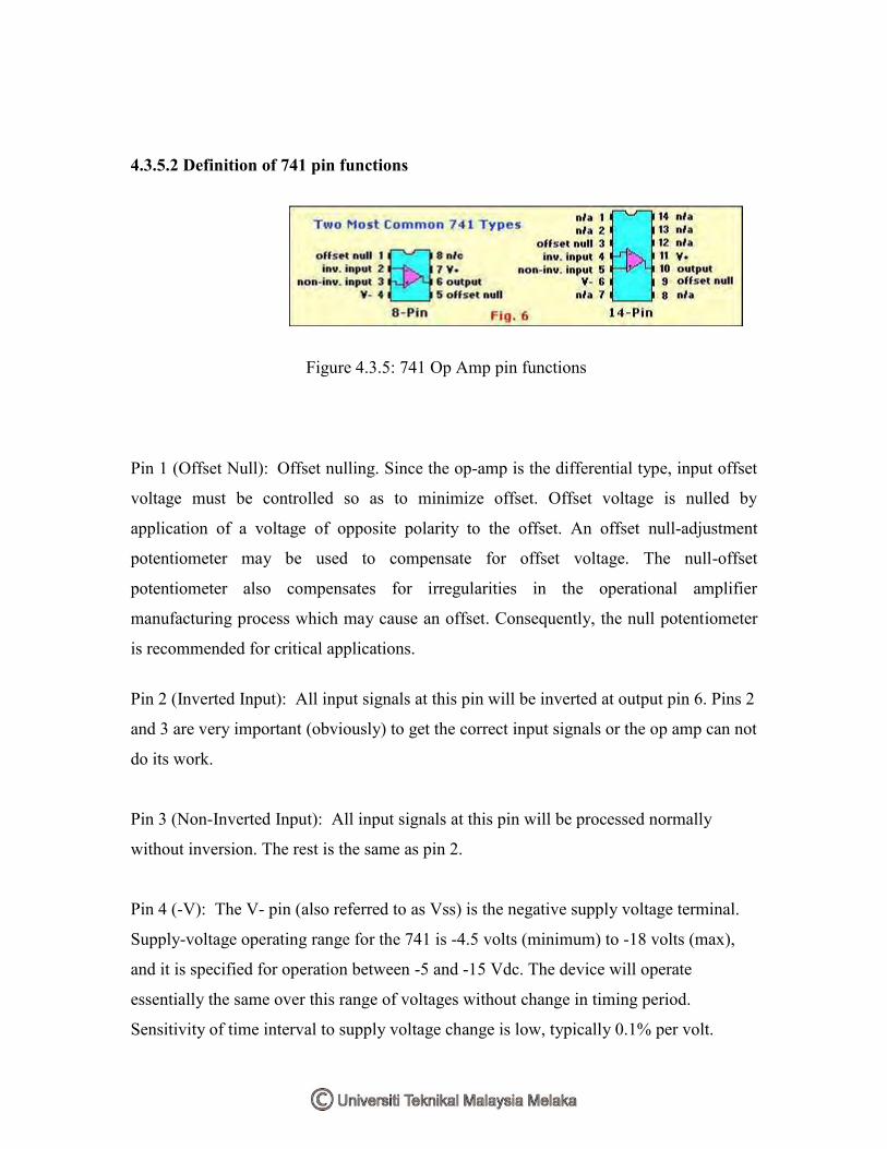
4.3.5.2 Definition of 741 pin functions
Figure 4.3.5: 741 Op Amp pin functions
Pin 1 (Offset Null): Offset nulling. Since the op-amp is the differential type, input offset
voltage must be controlled so as to minimize offset. Offset voltage is nulled by
application of a voltage of opposite polarity to the offset. An offset null-adjustment
potentiometer may be used to compensate for offset voltage. The null-offset
potentiometer also compensates for irregularities in the operational amplifier
manufacturing process which may cause an offset. Consequently, the null potentiometer
is recommended for critical applications.
Pin 2 (Inverted Input): All input signals at this pin will be inverted at output pin 6. Pins 2
and 3 are very important (obviously) to get the correct input signals or the op amp can not
do its work.
Pin 3 (Non-Inverted Input): All input signals at this pin will be processed normally
without inversion. The rest is the same as pin 2.
Pin 4 (-V): The V- pin (also referred to as Vss) is the negative supply voltage terminal.
Supply-voltage operating range for the 741 is -4.5 volts (minimum) to -18 volts (max),
and it is specified for operation between -5 and -15 Vdc. The device will operate
essentially the same over this range of voltages without change in timing period.
Sensitivity of time interval to supply voltage change is low, typically 0.1% per volt.
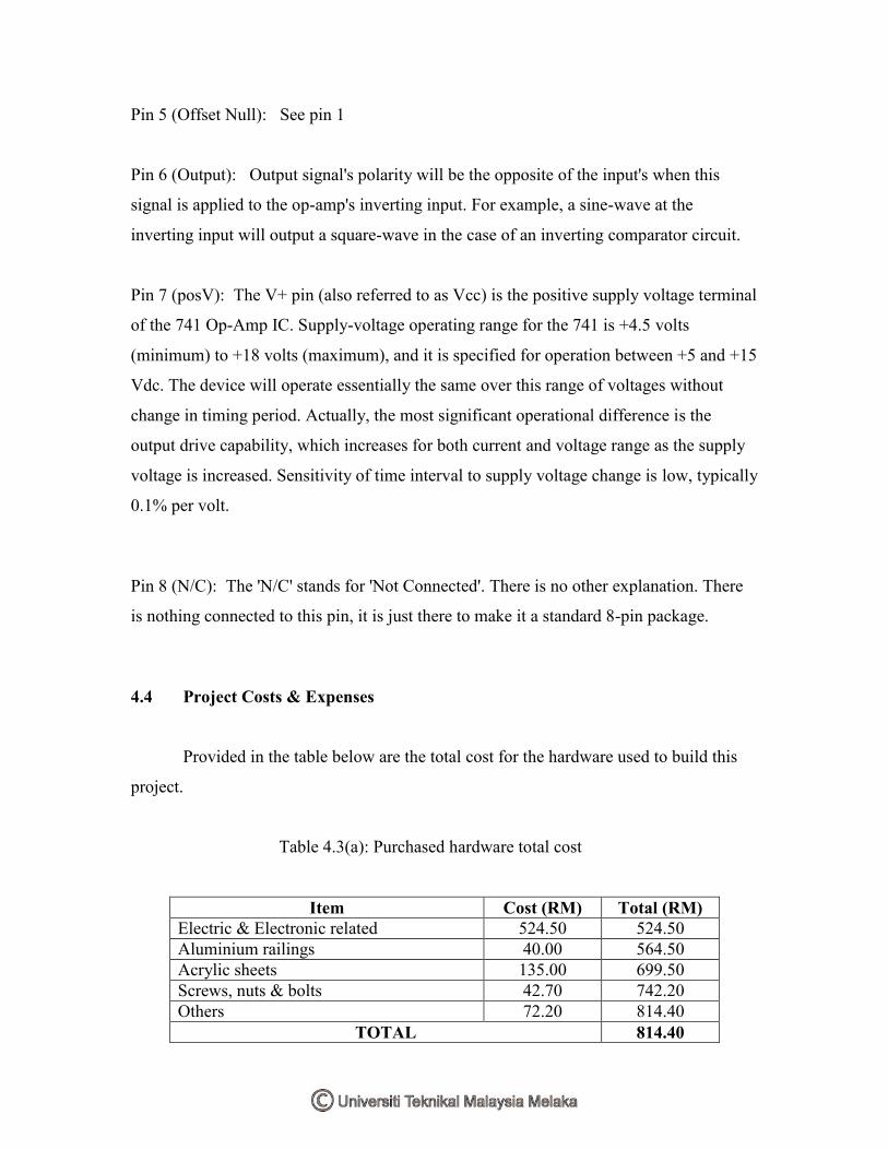
Pin 5 (Offset Null): See pin 1
Pin 6 (Output): Output signal's polarity will be the opposite of the input's when this
signal is applied to the op-amp's inverting input. For example, a sine-wave at the
inverting input will output a square-wave in the case of an inverting comparator circuit.
Pin 7 (posV): The V+ pin (also referred to as Vcc) is the positive supply voltage terminal
of the 741 Op-Amp IC. Supply-voltage operating range for the 741 is +4.5 volts
(minimum) to +18 volts (maximum), and it is specified for operation between +5 and +15
Vdc. The device will operate essentially the same over this range of voltages without
change in timing period. Actually, the most significant operational difference is the
output drive capability, which increases for both current and voltage range as the supply
voltage is increased. Sensitivity of time interval to supply voltage change is low, typically
0.1% per volt.
Pin 8 (N/C): The 'N/C' stands for 'Not Connected'. There is no other explanation. There
is nothing connected to this pin, it is just there to make it a standard 8-pin package.
4.4 Project Costs & Expenses
Provided in the table below are the total cost for the hardware used to build this
project.
Table 4.3(a): Purchased hardware total cost
Item Cost (RM) Total (RM) Electric & Electronic related 524.50 524.50 Aluminium railings 40.00 564.50 Acrylic sheets 135.00 699.50 Screws, nuts & bolts 42.70 742.20 Others 72.20 814.40
TOTAL 814.40
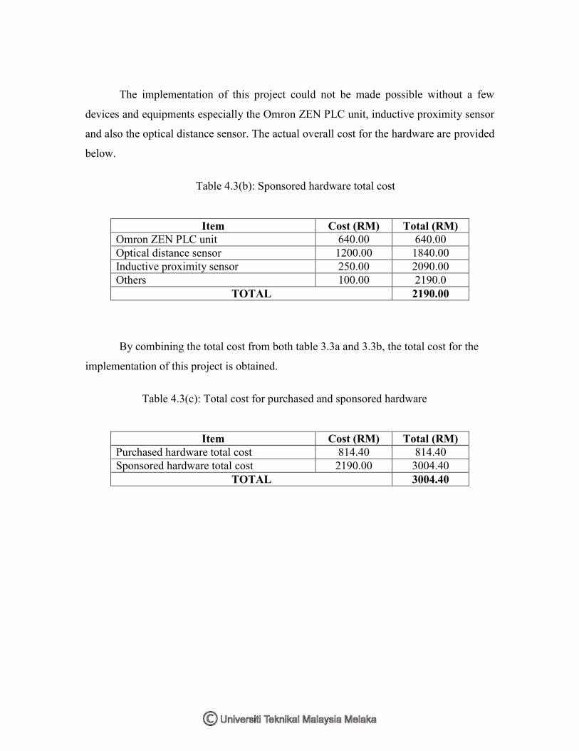
The implementation of this project could not be made possible without a few
devices and equipments especially the Omron ZEN PLC unit, inductive proximity sensor
and also the optical distance sensor. The actual overall cost for the hardware are provided
below.
Table 4.3(b): Sponsored hardware total cost
Item Cost (RM) Total (RM) Omron ZEN PLC unit 640.00 640.00 Optical distance sensor 1200.00 1840.00 Inductive proximity sensor 250.00 2090.00 Others 100.00 2190.0
TOTAL 2190.00
By combining the total cost from both table 3.3a and 3.3b, the total cost for the
implementation of this project is obtained.
Table 4.3(c): Total cost for purchased and sponsored hardware
Item Cost (RM) Total (RM) Purchased hardware total cost 814.40 814.40 Sponsored hardware total cost 2190.00 3004.40
TOTAL 3004.40
CHAPTER 5
RESULT & DISCUSSION
5.1 Result
The result achieved from the implementation of this project is the design
and construction of home automation and lighting control applicable for homes and also
teaching purpose. The stated objectives for this project has been achieved almost fully
with only the garden management module could not be completed due to various
problems and challenges.
During the implementation of the project, there has been problems arising but all
of them were solved using troubleshooting techniques. The implementation of this project
are also successful according to the Gantt chart and also the flow chart.
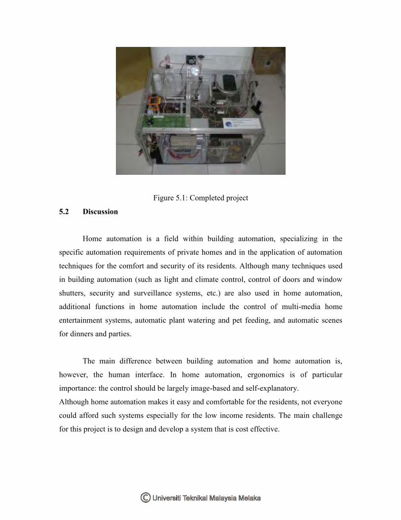
Figure 5.1: Completed project
5.2 Discussion
Home automation is a field within building automation, specializing in the
specific automation requirements of private homes and in the application of automation
techniques for the comfort and security of its residents. Although many techniques used
in building automation (such as light and climate control, control of doors and window
shutters, security and surveillance systems, etc.) are also used in home automation,
additional functions in home automation include the control of multi-media home
entertainment systems, automatic plant watering and pet feeding, and automatic scenes
for dinners and parties.
The main difference between building automation and home automation is,
however, the human interface. In home automation, ergonomics is of particular
importance: the control should be largely image-based and self-explanatory.
Although home automation makes it easy and comfortable for the residents, not everyone
could afford such systems especially for the low income residents. The main challenge
for this project is to design and develop a system that is cost effective.

5.2.1 Problems & Challenges
The implementation of the project is not a simple and easy one as imagined by
many when the idea for a smart home project was proposed as many would be looking
into the simplicity and basic functions of the circuits rather than the importance of the
circuits arrangements on the house module.
Certain components that need to be used for the circuit are unavailable
in the simulation software. 3 softwares are used, which are Multisim 7, Proteus 7 and
ZEN support for PLC to solve this problem. Troubleshooting the circuit created during
simulation stage is another hard part. Sometimes the circuit could not be simulated
properly due to human error and probably the computer’s malfunction or the connection
problems. Acquiring the components needed for the circuits is not as easy as it may
sound as certain components have a specific value and to fix this, another component
with a closer value or identically the same is replaced.
Another important thing is to make sure that the total load does not
exceed the maximum rating of power supply. The switching power supply provides a
power of a maximum 2.1 Amps for the 24V and 3A for the 12V power supply. The
circuits have to be designed to use the most minimum power from the power supply.
Designing a low cost project is one of the hardest part as the cost for each components
have to be kept low. Arrangement also needs to be planned accordingly. Any mistake
here would cost waste of time, energy and difficulties in the future as sometimes the same
works have to be carried out twice.
The Garden Management module was not completed due to a few reasons. There
was a problem finding the components and parts needed especially the tweeter to transmit
ultrasonic frequency. The designed circuit was not functioning and the troubleshooting
failed and there was insufficient time and budget for this module.

CHAPTER 6
CONCLUSION & RECOMMENDATIONS
6.1 Recommendations
The modules that form this project is just a simple circuit connected with each
other to form an automation system. There are many rooms to improve the existing ones
to make it perform better in the future. For example, we will use the indoor ventilation
control that uses the temperature sensing circuit. The circuit detects the change in the
temperature by using a NTC type thermistor which is the most basic device in
temperature measurement. This circuit can be improved by probably using an air
humidity sensor and can be added with a temperature display so that the current
temperature is shown to the user.
Other than that, each designed module can be upgraded easily. Other automation
system can also be added to improve the current system. Hopefully someone will make
good use of this project and make a better one of it in the near future.
To make it better especially cost saving, the PLC can be replaced with the
application of PIC. This is especially true since PICs are robust, compact and smaller in
size. The application of PLC is also suitable but as a small scale application demands, it
is better to go with the PIC. The reason for this project to continue with the use of PLC
despite the better use of PIC is because the PLC is obtained for free.

6.2 Conclusion
It can be concluded that up to date, all the objectives are not far away to be
achieved. The project is well going and proceeding according to the flow chart and Gantt
chart planning or probably even faster than expected. There are various problems and
challenges faced but so far each and every one is solved with the guidance of the project
supervisor and with the help of my fellow collegues. This project has undoubtly
improved my understanding in electrical devices, circuit and increased my ability in
project managing and planning. Hopefully, upon the completion of this project, the field
of home automation will be a major aspect in universities in Malaysia as the current
homes have a good potential to be converted into smart homes. This will reflect Malaysia
as a modern and technologically advanced country.

REFERENCES
[1] Joseph F. McPartland, Brian J. McPartland, Handbook of Practical
Electrical Design Third Edition, McGraw-Hill, 1998
[2] Homer L. Davidson, Consumer Electronics Troubleshooting And Repair
Handbook, McGraw-Hill, 1999
[3] William H. Yeadon, Alan W. Yeadon, Handbook of Small Electric
Motors, McGraw-Hill, 2001
[4] Keith Billings, Switchmode Power Supply Handbook Second Edition,
McGraw Hill, 1999
[5] David L. Terrell, Op Amps Design, Application And Troubleshooting
Second Edition, Butterworth-Heinemann, 1996
[6] Ian Hickman, Bill Travis, The EDN Designer’s Companion,
Butterworth-Heinemann, 1994
[7] Electronic & Hobby Projects
http://www.electronic-circuits-diagrams.com/index.shtml
[8] Electronic & Hobby Projects
http://www.electronics-lab.com/projects/index.html
[9] Electronic & Hobby Projects
http://www.educypedia.be/electronics/circuitsopto.htm
[10] Electronic & Hobby Projects
http://www.technick.net/public/code/circuits.php
[11] Smart Home
http://www.iproperty.com.my/homeservice/mhsmart/mhsmart.asp
[12] Wikipedia, PLC
http://www.wikipedia.org
[13] 555 Timer Article
http://www.kpsec.freeuk.com/555timer.htm
[14] Components Datasheet
http://www.datasheetcatalogs.com

LM555TimerGeneral DescriptionThe LM555 is a highly stable device for generating accuratetime delays or oscillation. Additional terminals are providedfor triggering or resetting if desired. In the time delay mode ofoperation, the time is precisely controlled by one externalresistor and capacitor. For astable operation as an oscillator,the free running frequency and duty cycle are accuratelycontrolled with two external resistors and one capacitor. Thecircuit may be triggered and reset on falling waveforms, andthe output circuit can source or sink up to 200mA or driveTTL circuits.
Featuresn Direct replacement for SE555/NE555n Timing from microseconds through hoursn Operates in both astable and monostable modesn Adjustable duty cyclen Output can source or sink 200 mAn Output and supply TTL compatiblen Temperature stability better than 0.005% per ˚Cn Normally on and normally off outputn Available in 8-pin MSOP package
Applicationsn Precision timingn Pulse generationn Sequential timingn Time delay generationn Pulse width modulationn Pulse position modulationn Linear ramp generator
Schematic Diagram
00785101
July 2006LM
555Tim
er
© 2006 National Semiconductor Corporation DS007851 www.national.com

Connection DiagramDual-In-Line, Small Outline
and Molded Mini Small Outline Packages
00785103
Top View
Ordering InformationPackage Part Number Package Marking Media Transport NSC Drawing
8-Pin SOIC LM555CM LM555CM RailsM08A
LM555CMX LM555CM 2.5k Units Tape and Reel
8-Pin MSOP LM555CMM Z55 1k Units Tape and ReelMUA08A
LM555CMMX Z55 3.5k Units Tape and Reel
8-Pin MDIP LM555CN LM555CN Rails N08E
LM55
5
www.national.com 2

Absolute Maximum Ratings (Note 2)
If Military/Aerospace specified devices are required,please contact the National Semiconductor Sales Office/Distributors for availability and specifications.
Supply Voltage +18V
Power Dissipation (Note 3)
LM555CM, LM555CN 1180 mW
LM555CMM 613 mW
Operating Temperature Ranges
LM555C 0˚C to +70˚C
Storage Temperature Range −65˚C to +150˚C
Soldering Information
Dual-In-Line Package
Soldering (10 Seconds) 260˚C
Small Outline Packages
(SOIC and MSOP)
Vapor Phase (60 Seconds) 215˚C
Infrared (15 Seconds) 220˚C
See AN-450 “Surface Mounting Methods and Their Effecton Product Reliability” for other methods of solderingsurface mount devices.
Electrical Characteristics (Notes 1, 2)
(TA = 25˚C, VCC = +5V to +15V, unless othewise specified)
Parameter Conditions Limits Units
LM555C
Min Typ Max
Supply Voltage 4.5 16 V
Supply Current VCC = 5V, RL = ∞VCC = 15V, RL = ∞(Low State) (Note 4)
310
615 mA
Timing Error, Monostable
Initial Accuracy 1 %
Drift with Temperature RA = 1k to 100kΩ, 50 ppm/˚C
C = 0.1µF, (Note 5)
Accuracy over Temperature 1.5 %
Drift with Supply 0.1 %/V
Timing Error, Astable
Initial Accuracy 2.25 %
Drift with Temperature RA, RB = 1k to 100kΩ, 150 ppm/˚C
C = 0.1µF, (Note 5)
Accuracy over Temperature 3.0 %
Drift with Supply 0.30 %/V
Threshold Voltage 0.667 x VCC
Trigger Voltage VCC = 15V 5 V
VCC = 5V 1.67 V
Trigger Current 0.5 0.9 µA
Reset Voltage 0.4 0.5 1 V
Reset Current 0.1 0.4 mA
Threshold Current (Note 6) 0.1 0.25 µA
Control Voltage Level VCC = 15VVCC = 5V
92.6
103.33
114
V
Pin 7 Leakage Output High 1 100 nA
Pin 7 Sat (Note 7)
Output Low VCC = 15V, I7 = 15mA 180 mV
Output Low VCC = 4.5V, I7 = 4.5mA 80 200 mV
LM555
www.national.com3

Electrical Characteristics (Notes 1, 2) (Continued)(TA = 25˚C, VCC = +5V to +15V, unless othewise specified)
Parameter Conditions Limits Units
LM555C
Min Typ Max
Output Voltage Drop (Low) VCC = 15V
ISINK = 10mA 0.1 0.25 V
ISINK = 50mA 0.4 0.75 V
ISINK = 100mA 2 2.5 V
ISINK = 200mA 2.5 V
VCC = 5V
ISINK = 8mA V
ISINK = 5mA 0.25 0.35 V
Output Voltage Drop (High) ISOURCE = 200mA, VCC = 15V 12.5 V
ISOURCE = 100mA, VCC = 15V 12.75 13.3 V
VCC = 5V 2.75 3.3 V
Rise Time of Output 100 ns
Fall Time of Output 100 ns
Note 1: All voltages are measured with respect to the ground pin, unless otherwise specified.
Note 2: Absolute Maximum Ratings indicate limits beyond which damage to the device may occur. Operating Ratings indicate conditions for which the device isfunctional, but do not guarantee specific performance limits. Electrical Characteristics state DC and AC electrical specifications under particular test conditions whichguarantee specific performance limits. This assumes that the device is within the Operating Ratings. Specifications are not guaranteed for parameters where no limitis given, however, the typical value is a good indication of device performance.
Note 3: For operating at elevated temperatures the device must be derated above 25˚C based on a +150˚C maximum junction temperature and a thermalresistance of 106˚C/W (DIP), 170˚C/W (S0-8), and 204˚C/W (MSOP) junction to ambient.
Note 4: Supply current when output high typically 1 mA less at VCC = 5V.
Note 5: Tested at VCC = 5V and VCC = 15V.
Note 6: This will determine the maximum value of RA + RB for 15V operation. The maximum total (RA + RB) is 20MΩ.
Note 7: No protection against excessive pin 7 current is necessary providing the package dissipation rating will not be exceeded.
Note 8: Refer to RETS555X drawing of military LM555H and LM555J versions for specifications.
LM55
5
www.national.com 4
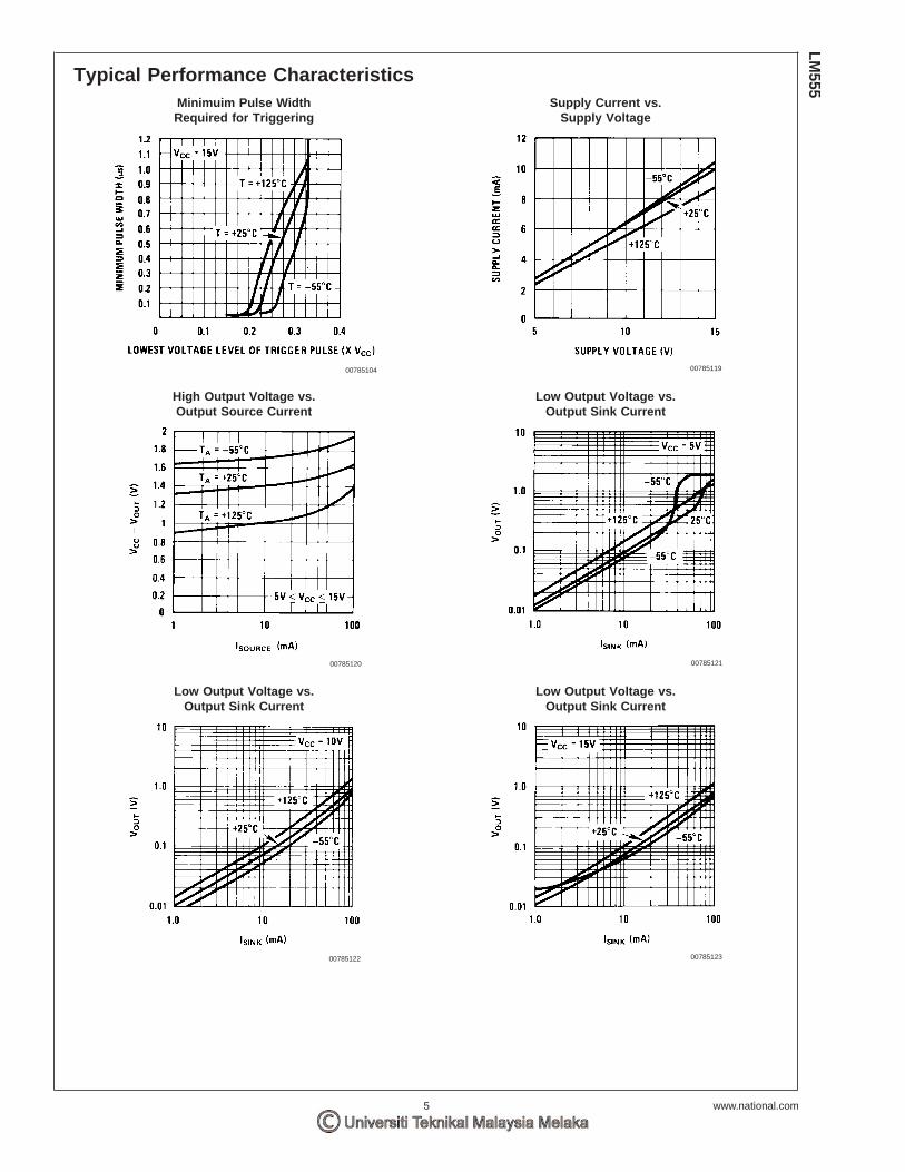
Typical Performance CharacteristicsMinimuim Pulse WidthRequired for Triggering
Supply Current vs.Supply Voltage
00785104 00785119
High Output Voltage vs.Output Source Current
Low Output Voltage vs.Output Sink Current
00785120 00785121
Low Output Voltage vs.Output Sink Current
Low Output Voltage vs.Output Sink Current
00785122 00785123
LM555
www.national.com5
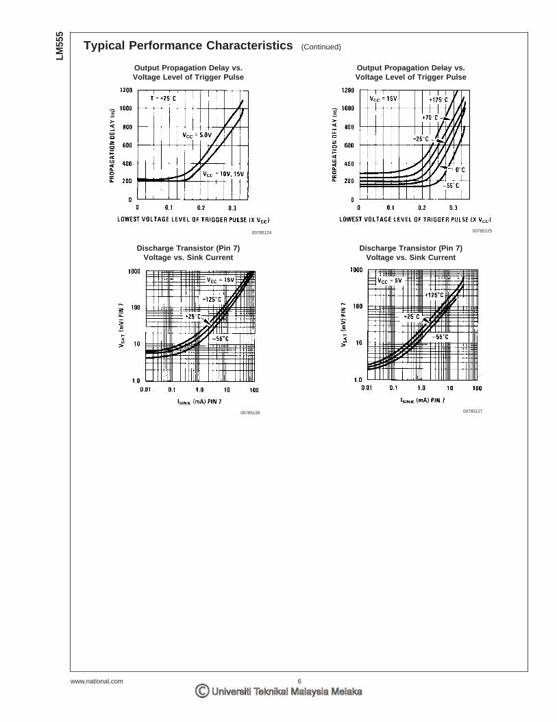
Typical Performance Characteristics (Continued)
Output Propagation Delay vs.Voltage Level of Trigger Pulse
Output Propagation Delay vs.Voltage Level of Trigger Pulse
00785124 00785125
Discharge Transistor (Pin 7)Voltage vs. Sink Current
Discharge Transistor (Pin 7)Voltage vs. Sink Current
00785126 00785127
LM55
5
www.national.com 6
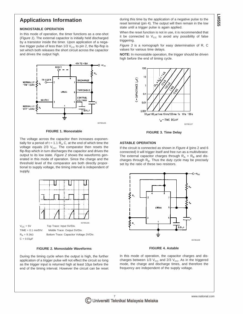
Applications Information
MONOSTABLE OPERATION
In this mode of operation, the timer functions as a one-shot(Figure 1). The external capacitor is initially held dischargedby a transistor inside the timer. Upon application of a nega-tive trigger pulse of less than 1/3 VCC to pin 2, the flip-flop isset which both releases the short circuit across the capacitorand drives the output high.
The voltage across the capacitor then increases exponen-tially for a period of t = 1.1 RA C, at the end of which time thevoltage equals 2/3 VCC. The comparator then resets theflip-flop which in turn discharges the capacitor and drives theoutput to its low state. Figure 2 shows the waveforms gen-erated in this mode of operation. Since the charge and thethreshold level of the comparator are both directly propor-tional to supply voltage, the timing interval is independent ofsupply.
During the timing cycle when the output is high, the furtherapplication of a trigger pulse will not effect the circuit so longas the trigger input is returned high at least 10µs before theend of the timing interval. However the circuit can be reset
during this time by the application of a negative pulse to thereset terminal (pin 4). The output will then remain in the lowstate until a trigger pulse is again applied.
When the reset function is not in use, it is recommended thatit be connected to VCC to avoid any possibility of falsetriggering.
Figure 3 is a nomograph for easy determination of R, Cvalues for various time delays.
NOTE: In monostable operation, the trigger should be drivenhigh before the end of timing cycle.
ASTABLE OPERATION
If the circuit is connected as shown in Figure 4 (pins 2 and 6connected) it will trigger itself and free run as a multivibrator.The external capacitor charges through RA + RB and dis-charges through RB. Thus the duty cycle may be preciselyset by the ratio of these two resistors.
In this mode of operation, the capacitor charges and dis-charges between 1/3 VCC and 2/3 VCC. As in the triggeredmode, the charge and discharge times, and therefore thefrequency are independent of the supply voltage.
00785105
FIGURE 1. Monostable
00785106
VCC = 5V Top Trace: Input 5V/Div.
TIME = 0.1 ms/DIV. Middle Trace: Output 5V/Div.
RA = 9.1kΩ Bottom Trace: Capacitor Voltage 2V/Div.
C = 0.01µF
FIGURE 2. Monostable Waveforms
00785107
FIGURE 3. Time Delay
00785108
FIGURE 4. Astable
LM555
www.national.com7

Applications Information (Continued)
Figure 5 shows the waveforms generated in this mode ofoperation.
The charge time (output high) is given by:
t1 = 0.693 (RA + RB) C
And the discharge time (output low) by:
t2 = 0.693 (RB) C
Thus the total period is:
T = t1 + t2 = 0.693 (RA +2RB) C
The frequency of oscillation is:
Figure 6 may be used for quick determination of these RCvalues.
The duty cycle is:
FREQUENCY DIVIDER
The monostable circuit of Figure 1 can be used as a fre-quency divider by adjusting the length of the timing cycle.Figure 7 shows the waveforms generated in a divide by threecircuit.
PULSE WIDTH MODULATOR
When the timer is connected in the monostable mode andtriggered with a continuous pulse train, the output pulsewidth can be modulated by a signal applied to pin 5. Figure8 shows the circuit, and in Figure 9 are some waveformexamples.
00785109
VCC = 5V Top Trace: Output 5V/Div.
TIME = 20µs/DIV. Bottom Trace: Capacitor Voltage 1V/Div.
RA = 3.9kΩ
RB = 3kΩ
C = 0.01µF
FIGURE 5. Astable Waveforms
00785110
FIGURE 6. Free Running Frequency
00785111
VCC = 5V Top Trace: Input 4V/Div.
TIME = 20µs/DIV. Middle Trace: Output 2V/Div.
RA = 9.1kΩ Bottom Trace: Capacitor 2V/Div.
C = 0.01µF
FIGURE 7. Frequency Divider
00785112
FIGURE 8. Pulse Width Modulator
LM55
5
www.national.com 8

Applications Information (Continued)
PULSE POSITION MODULATOR
This application uses the timer connected for astable opera-tion, as in Figure 10, with a modulating signal again appliedto the control voltage terminal. The pulse position varies withthe modulating signal, since the threshold voltage and hencethe time delay is varied. Figure 11 shows the waveformsgenerated for a triangle wave modulation signal.
LINEAR RAMP
When the pullup resistor, RA, in the monostable circuit isreplaced by a constant current source, a linear ramp isgenerated. Figure 12 shows a circuit configuration that willperform this function.
Figure 13 shows waveforms generated by the linear ramp.
The time interval is given by:
VBE . 0.6V
00785113
VCC = 5V Top Trace: Modulation 1V/Div.
TIME = 0.2 ms/DIV. Bottom Trace: Output Voltage 2V/Div.
RA = 9.1kΩ
C = 0.01µF
FIGURE 9. Pulse Width Modulator
00785114
FIGURE 10. Pulse Position Modulator
00785115
VCC = 5V Top Trace: Modulation Input 1V/Div.
TIME = 0.1 ms/DIV. Bottom Trace: Output 2V/Div.
RA = 3.9kΩ
RB = 3kΩ
C = 0.01µF
FIGURE 11. Pulse Position Modulator
00785116
FIGURE 12.
LM555
www.national.com9

Applications Information (Continued)
50% DUTY CYCLE OSCILLATOR
For a 50% duty cycle, the resistors RA and RB may beconnected as in Figure 14. The time period for the outputhigh is the same as previous, t1 = 0.693 RA C. For the outputlow it is t2 =
Thus the frequency of oscillation is
Note that this circuit will not oscillate if RB is greater than 1/2RA because the junction of RA and RB cannot bring pin 2down to 1/3 VCC and trigger the lower comparator.
ADDITIONAL INFORMATION
Adequate power supply bypassing is necessary to protectassociated circuitry. Minimum recommended is 0.1µF in par-allel with 1µF electrolytic.
Lower comparator storage time can be as long as 10µswhen pin 2 is driven fully to ground for triggering. This limitsthe monostable pulse width to 10µs minimum.
Delay time reset to output is 0.47µs typical. Minimum resetpulse width must be 0.3µs, typical.
Pin 7 current switches within 30ns of the output (pin 3)voltage.
00785117
VCC = 5V Top Trace: Input 3V/Div.
TIME = 20µs/DIV. Middle Trace: Output 5V/Div.
R1 = 47kΩ Bottom Trace: Capacitor Voltage 1V/Div.
R2 = 100kΩ
RE = 2.7 kΩ
C = 0.01 µF
FIGURE 13. Linear Ramp
00785118
FIGURE 14. 50% Duty Cycle Oscillator
LM55
5
www.national.com 10
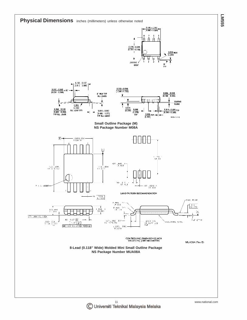
Physical Dimensions inches (millimeters) unless otherwise noted
Small Outline Package (M)NS Package Number M08A
8-Lead (0.118” Wide) Molded Mini Small Outline PackageNS Package Number MUA08A
LM555
www.national.com11
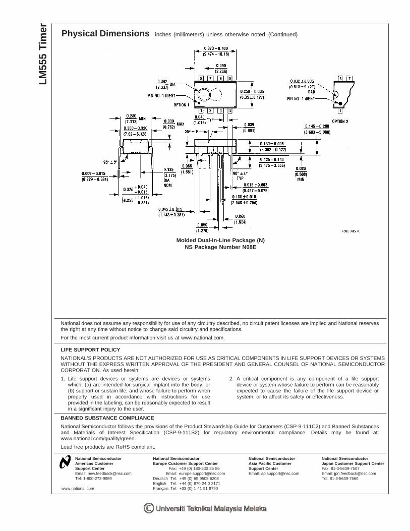
Physical Dimensions inches (millimeters) unless otherwise noted (Continued)
Molded Dual-In-Line Package (N)NS Package Number N08E
National does not assume any responsibility for use of any circuitry described, no circuit patent licenses are implied and National reservesthe right at any time without notice to change said circuitry and specifications.
For the most current product information visit us at www.national.com.
LIFE SUPPORT POLICY
NATIONAL’S PRODUCTS ARE NOT AUTHORIZED FOR USE AS CRITICAL COMPONENTS IN LIFE SUPPORT DEVICES OR SYSTEMSWITHOUT THE EXPRESS WRITTEN APPROVAL OF THE PRESIDENT AND GENERAL COUNSEL OF NATIONAL SEMICONDUCTORCORPORATION. As used herein:
1. Life support devices or systems are devices or systemswhich, (a) are intended for surgical implant into the body, or(b) support or sustain life, and whose failure to perform whenproperly used in accordance with instructions for useprovided in the labeling, can be reasonably expected to resultin a significant injury to the user.
2. A critical component is any component of a life supportdevice or system whose failure to perform can be reasonablyexpected to cause the failure of the life support device orsystem, or to affect its safety or effectiveness.
BANNED SUBSTANCE COMPLIANCE
National Semiconductor follows the provisions of the Product Stewardship Guide for Customers (CSP-9-111C2) and Banned Substancesand Materials of Interest Specification (CSP-9-111S2) for regulatory environmental compliance. Details may be found at:www.national.com/quality/green.
Lead free products are RoHS compliant.
National SemiconductorAmericas CustomerSupport CenterEmail: [email protected]: 1-800-272-9959
National SemiconductorEurope Customer Support Center
Fax: +49 (0) 180-530 85 86Email: [email protected]
Deutsch Tel: +49 (0) 69 9508 6208English Tel: +44 (0) 870 24 0 2171Français Tel: +33 (0) 1 41 91 8790
National SemiconductorAsia Pacific CustomerSupport CenterEmail: [email protected]
National SemiconductorJapan Customer Support CenterFax: 81-3-5639-7507Email: [email protected]: 81-3-5639-7560
www.national.com
LM55
5Ti
mer
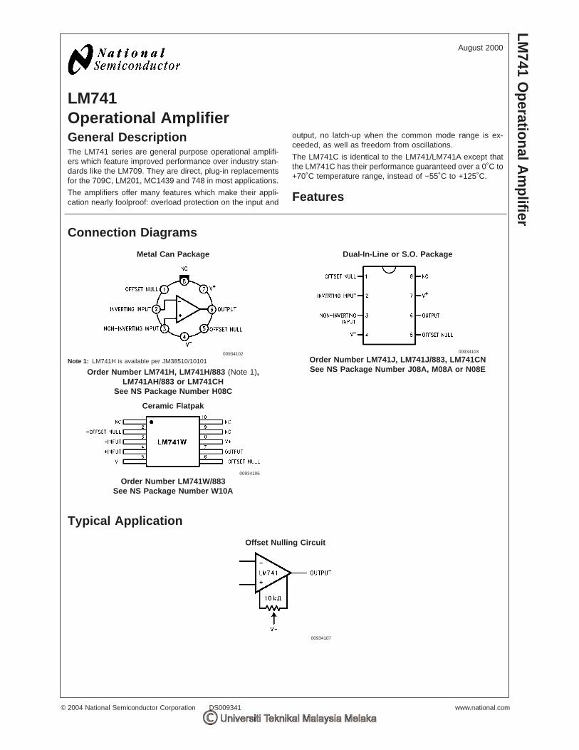
LM741Operational AmplifierGeneral DescriptionThe LM741 series are general purpose operational amplifi-ers which feature improved performance over industry stan-dards like the LM709. They are direct, plug-in replacementsfor the 709C, LM201, MC1439 and 748 in most applications.
The amplifiers offer many features which make their appli-cation nearly foolproof: overload protection on the input and
output, no latch-up when the common mode range is ex-ceeded, as well as freedom from oscillations.
The LM741C is identical to the LM741/LM741A except thatthe LM741C has their performance guaranteed over a 0˚C to+70˚C temperature range, instead of −55˚C to +125˚C.
Features
Connection Diagrams
Metal Can Package Dual-In-Line or S.O. Package
00934102
Note 1: LM741H is available per JM38510/10101
Order Number LM741H, LM741H/883 (Note 1),LM741AH/883 or LM741CH
See NS Package Number H08C
00934103
Order Number LM741J, LM741J/883, LM741CNSee NS Package Number J08A, M08A or N08E
Ceramic Flatpak
00934106
Order Number LM741W/883See NS Package Number W10A
Typical Application
Offset Nulling Circuit
00934107
August 2000LM
741O
perationalAm
plifier
© 2004 National Semiconductor Corporation DS009341 www.national.com
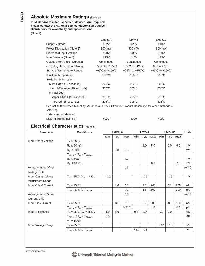
Absolute Maximum Ratings (Note 2)
If Military/Aerospace specified devices are required,please contact the National Semiconductor Sales Office/Distributors for availability and specifications.
(Note 7)
LM741A LM741 LM741C
Supply Voltage ±22V ±22V ±18V
Power Dissipation (Note 3) 500 mW 500 mW 500 mW
Differential Input Voltage ±30V ±30V ±30V
Input Voltage (Note 4) ±15V ±15V ±15V
Output Short Circuit Duration Continuous Continuous Continuous
Operating Temperature Range −55˚C to +125˚C −55˚C to +125˚C 0˚C to +70˚C
Storage Temperature Range −65˚C to +150˚C −65˚C to +150˚C −65˚C to +150˚C
Junction Temperature 150˚C 150˚C 100˚C
Soldering Information
N-Package (10 seconds) 260˚C 260˚C 260˚C
J- or H-Package (10 seconds) 300˚C 300˚C 300˚C
M-Package
Vapor Phase (60 seconds) 215˚C 215˚C 215˚C
Infrared (15 seconds) 215˚C 215˚C 215˚C
See AN-450 “Surface Mounting Methods and Their Effect on Product Reliability” for other methods ofsoldering
surface mount devices.
ESD Tolerance (Note 8) 400V 400V 400V
Electrical Characteristics (Note 5)
Parameter Conditions LM741A LM741 LM741C Units
Min Typ Max Min Typ Max Min Typ Max
Input Offset Voltage TA = 25˚C
RS ≤ 10 kΩ 1.0 5.0 2.0 6.0 mV
RS ≤ 50Ω 0.8 3.0 mV
TAMIN ≤ TA ≤ TAMAX
RS ≤ 50Ω 4.0 mV
RS ≤ 10 kΩ 6.0 7.5 mV
Average Input Offset 15 µV/˚C
Voltage Drift
Input Offset Voltage TA = 25˚C, VS = ±20V ±10 ±15 ±15 mV
Adjustment Range
Input Offset Current TA = 25˚C 3.0 30 20 200 20 200 nA
TAMIN ≤ TA ≤ TAMAX 70 85 500 300 nA
Average Input Offset 0.5 nA/˚C
Current Drift
Input Bias Current TA = 25˚C 30 80 80 500 80 500 nA
TAMIN ≤ TA ≤ TAMAX 0.210 1.5 0.8 µA
Input Resistance TA = 25˚C, VS = ±20V 1.0 6.0 0.3 2.0 0.3 2.0 MΩTAMIN ≤ TA ≤ TAMAX, 0.5 MΩVS = ±20V
Input Voltage Range TA = 25˚C ±12 ±13 V
TAMIN ≤ TA ≤ TAMAX ±12 ±13 V
LM74
1
www.national.com 2

Electrical Characteristics (Note 5) (Continued)
Parameter Conditions LM741A LM741 LM741C Units
Min Typ Max Min Typ Max Min Typ Max
Large Signal Voltage Gain TA = 25˚C, RL ≥ 2 kΩVS = ±20V, VO = ±15V 50 V/mV
VS = ±15V, VO = ±10V 50 200 20 200 V/mV
TAMIN ≤ TA ≤ TAMAX,
RL ≥ 2 kΩ,
VS = ±20V, VO = ±15V 32 V/mV
VS = ±15V, VO = ±10V 25 15 V/mV
VS = ±5V, VO = ±2V 10 V/mV
Output Voltage Swing VS = ±20V
RL ≥ 10 kΩ ±16 V
RL ≥ 2 kΩ ±15 V
VS = ±15V
RL ≥ 10 kΩ ±12 ±14 ±12 ±14 V
RL ≥ 2 kΩ ±10 ±13 ±10 ±13 V
Output Short Circuit TA = 25˚C 10 25 35 25 25 mA
Current TAMIN ≤ TA ≤ TAMAX 10 40 mA
Common-Mode TAMIN ≤ TA ≤ TAMAX
Rejection Ratio RS ≤ 10 kΩ, VCM = ±12V 70 90 70 90 dB
RS ≤ 50Ω, VCM = ±12V 80 95 dB
Supply Voltage Rejection TAMIN ≤ TA ≤ TAMAX,
Ratio VS = ±20V to VS = ±5V
RS ≤ 50Ω 86 96 dB
RS ≤ 10 kΩ 77 96 77 96 dB
Transient Response TA = 25˚C, Unity Gain
Rise Time 0.25 0.8 0.3 0.3 µs
Overshoot 6.0 20 5 5 %
Bandwidth (Note 6) TA = 25˚C 0.437 1.5 MHz
Slew Rate TA = 25˚C, Unity Gain 0.3 0.7 0.5 0.5 V/µs
Supply Current TA = 25˚C 1.7 2.8 1.7 2.8 mA
Power Consumption TA = 25˚C
VS = ±20V 80 150 mW
VS = ±15V 50 85 50 85 mW
LM741A VS = ±20V
TA = TAMIN 165 mW
TA = TAMAX 135 mW
LM741 VS = ±15V
TA = TAMIN 60 100 mW
TA = TAMAX 45 75 mW
Note 2: “Absolute Maximum Ratings” indicate limits beyond which damage to the device may occur. Operating Ratings indicate conditions for which the device isfunctional, but do not guarantee specific performance limits.
LM741
www.national.com3

Electrical Characteristics (Note 5) (Continued)Note 3: For operation at elevated temperatures, these devices must be derated based on thermal resistance, and Tj max. (listed under “Absolute MaximumRatings”). Tj = TA + (θjA PD).
Thermal Resistance Cerdip (J) DIP (N) HO8 (H) SO-8 (M)
θjA (Junction to Ambient) 100˚C/W 100˚C/W 170˚C/W 195˚C/W
θjC (Junction to Case) N/A N/A 25˚C/W N/A
Note 4: For supply voltages less than ±15V, the absolute maximum input voltage is equal to the supply voltage.
Note 5: Unless otherwise specified, these specifications apply for VS = ±15V, −55˚C ≤ TA ≤ +125˚C (LM741/LM741A). For the LM741C/LM741E, thesespecifications are limited to 0˚C ≤ TA ≤ +70˚C.
Note 6: Calculated value from: BW (MHz) = 0.35/Rise Time(µs).
Note 7: For military specifications see RETS741X for LM741 and RETS741AX for LM741A.
Note 8: Human body model, 1.5 kΩ in series with 100 pF.
Schematic Diagram
00934101
LM74
1
www.national.com 4

Physical Dimensions inches (millimeters)unless otherwise noted
Metal Can Package (H)Order Number LM741H, LM741H/883, LM741AH/883, LM741AH-MIL or LM741CH
NS Package Number H08C
LM741
www.national.com5
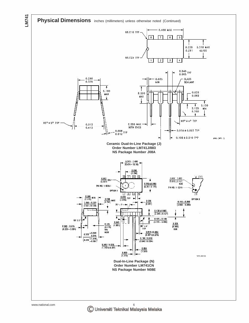
Physical Dimensions inches (millimeters) unless otherwise noted (Continued)
Ceramic Dual-In-Line Package (J)Order Number LM741J/883NS Package Number J08A
Dual-In-Line Package (N)Order Number LM741CN
NS Package Number N08E
LM74
1
www.national.com 6

Physical Dimensions inches (millimeters) unless otherwise noted (Continued)
10-Lead Ceramic Flatpak (W)Order Number LM741W/883, LM741WG-MPR or LM741WG/883
NS Package Number W10A
National does not assume any responsibility for use of any circuitry described, no circuit patent licenses are implied and National reservesthe right at any time without notice to change said circuitry and specifications.
For the most current product information visit us at www.national.com.
LIFE SUPPORT POLICY
NATIONAL’S PRODUCTS ARE NOT AUTHORIZED FOR USE AS CRITICAL COMPONENTS IN LIFE SUPPORT DEVICES OR SYSTEMSWITHOUT THE EXPRESS WRITTEN APPROVAL OF THE PRESIDENT AND GENERAL COUNSEL OF NATIONAL SEMICONDUCTORCORPORATION. As used herein:
1. Life support devices or systems are devices or systemswhich, (a) are intended for surgical implant into the body, or(b) support or sustain life, and whose failure to perform whenproperly used in accordance with instructions for useprovided in the labeling, can be reasonably expected to resultin a significant injury to the user.
2. A critical component is any component of a life supportdevice or system whose failure to perform can be reasonablyexpected to cause the failure of the life support device orsystem, or to affect its safety or effectiveness.
BANNED SUBSTANCE COMPLIANCE
National Semiconductor certifies that the products and packing materials meet the provisions of the Customer Products StewardshipSpecification (CSP-9-111C2) and the Banned Substances and Materials of Interest Specification (CSP-9-111S2) and contain no ‘‘BannedSubstances’’ as defined in CSP-9-111S2.
National SemiconductorAmericas CustomerSupport CenterEmail: [email protected]: 1-800-272-9959
National SemiconductorEurope Customer Support Center
Fax: +49 (0) 180-530 85 86Email: [email protected]
Deutsch Tel: +49 (0) 69 9508 6208English Tel: +44 (0) 870 24 0 2171Français Tel: +33 (0) 1 41 91 8790
National SemiconductorAsia Pacific CustomerSupport CenterEmail: [email protected]
National SemiconductorJapan Customer Support CenterFax: 81-3-5639-7507Email: [email protected]: 81-3-5639-7560
www.national.com
LM741
OperationalA
mplifier

DC PNPOUT1: Schließer / Öffner programmierbarOUT2: Schließer / Öffner programmierbar
oder analog (4...20 mA / 0...10V, skalierbar)
6 (TW max. = 10 m)
18...30 DC*
2 x 200
•
• / •
< 150
max. 50, einstellbar
I: max. 250; U: min. 5000
-10...60
IP 65, III
50000
EN 60947-5-2
Gehäuse: ZinkdruckgussFrontscheibe: Glas
LED-Fenster: Polycarbonat
Schließer; Öffner; analog
2 x gelbgrün
4-stellige alphanumerische Anzeige
* Betriebsspannung "supply class 2" gemäß cULus
Elektrische AusführungAusgangsfunktion
Lichtfleckdurchmesser [mm]
Betriebsspannung [V]
Strombelastbarkeit [mA]
Kurzschlussschutz, getaktet
Verpolungssicher / Überlastfest
Stromaufnahme [mA]
Messrate [Hz]
Bürde für Analogausgang [Ohm]
Umgebungstemperatur [°C]
Schutzart, Schutzklasse
Lebensdauer Laserdiode [h]
EMV
Werkstoff
Programmiermöglichkeiten
FunktionsanzeigeSchaltzustand [LED]Betrieb [LED]Abstandswert, Programmierung
Optoelektronische Sensoren und Systeme
\DA
TEN
\200
\DB-
FORM
\O1D
/01/
04
ifm electronic gmbh • Teichstraße 4 • 45 127 Essen Technische Änderungen behalten wir uns ohne Ankündigung vor! O1D100 - Seite 1/2 20. 09. 2006
O1D100Optischer Abstandssensor
O1DLF3KG
Sichtbares Laserlicht,Laserschutzklasse 2
4-stellige alphanumerischeAnzeige
Messbereich 0,2...10 m(bezogen auf weißes Papier,
90 % Remission)Hintergrundausblendung:
> 10...19 m1: 4-stellige alphanumerische Anzeige
LED Funktionsanzeigen2: Programmiertasten

M12 Steckverbindung
Achtung: LaserlichtLeistung <= 4,1 mW Wellenlänge = 650 nmPuls 1,3 nsNicht in den Strahl blickenKontakt mit Laserlicht vermeidenLaserklasse 2EN 60825-1:2003-10
Genauigkeit / Reproduzierbarkeitfür Messfrequenz 50 Hz
für Messfrequenz 1 Hz
Anschluss
Anschlussschema
Bemerkungen
\DA
TEN
\200
\DB-
FORM
\O1D
/01/
04
ifm electronic gmbh • Teichstraße 4 • 45 127 Essen 20. 09. 2006
4
2 1
3
Optoelektronische Sensoren und Systeme
Reproduzierbarkeit Genauigkeit
weiß grau weiß grau
(90 % Remission) (18 % Remission) (90 % Remission) (18 % Remission)
200...1000 mm ± 5,0 mm ± 7,5 mm ± 15,0 mm ± 18,0 mm
1000...2000 mm ± 5,5 mm ± 10,0 mm ± 15,0 mm ± 20,0 mm
2000...4000 mm ± 17,5 mm ± 22,5 mm ± 25,0 mm ± 32,0 mm
4000...6000 mm ± 27,5 mm ± 40,0 mm ± 35,0 mm ± 50,0 mm
6000...10000 mm ± 60,0 mm ± 70,0 mm
Tastweite auf Schwarz (6 % Remission) ≤ 4000 mmDie Werte gelten für- konstante Umweltbedingungen (23 °C / 960 hPa)- max. 8 klx Fremdlicht- min. Einschaltdauer von 10 Minuten.
Technische Änderungen behalten wir uns ohne Ankündigung vor! O1D100 - Seite 2/2
Reproduzierbarkeit Genauigkeit
weiß grau weiß grau
(90 % Remission) (18 % Remission) (90 % Remission) (18 % Remission)
200...1000 mm ± 4,0 mm ± 4,5 mm ± 14,0 mm ± 15,0 mm
1000...2000 mm ± 4,5 mm ± 6,0 mm ± 14,5 mm ± 16,0 mm
2000...4000 mm ± 13,5 mm ± 14,5 mm ± 23,5 mm ± 24,0 mm
4000...6000 mm ± 19,0 mm ± 21,0 mm ± 29,0 mm ± 31,0 mm
6000...10000 mm ± 37,0 mm ± 47,0 mm

DC PNPOUT1: normally open / closed programmableOUT2: normally open / closed programmableor analogue (4...20 mA / 0...10 V, scaleable)
6 (range max. = 10 m)
18...30 DC*
2 x 200
yes
yes / yes
< 150
max. 50, adjustable
I: max. 250; U: min. 5000
-10...60
IP 65, III
50000
EN 60947-5-2
Housing: diecast zincFront pane: glass
LED window: polycarbonate
N.O.; N.C.; analogue
2 x yellowgreen
4-digit alphanumeric display
* cULus - Class 2 source required
Electrical designOutput
Light spot diameter [mm]
Operating voltage [V]
Current rating [mA
Short-circuit protection
Reverse polarity / overload protection
Current consumption [mA]
Sampling rate [Hz]
Load for analogue output [ohms]
Operating temperature [°C]
Protection
Life of the laser diode [h]
EMC
Material
Programming options
Function displaySwitching status [LED]Power [LED]Distance, programming
Photoelectric sensors and systems
\DA
TEN
\200
\DB-
FORM
\O1D
/01/
04
ifm electronic gmbh • Teichstraße 4 • 45 127 Essen We reserve the right to make technical alterations without prior notice. O1D100 - page 1/2 20. 09. 2006
O1D100Optical distance sensor
O1DLF3KG
Visible laser light,Class 2 laser
4-digit alphanumeric display
Measuring range 0.2...10 m(Range referred to whitepaper, 90 % remission)
Background suppression:> 10...19 m
4-digit alphanumeric displayLED Function display
2: Programming buttons

M12 connector
Caution: Laser LightPower <= 4.1 mW wavelength = 650 nmpulse 1.3 nsDo not stare into beamAvoid exposureClass 2 laser productEN 60825-1:2003-10
Repeatability accuracyfor sampling rate 50 Hz:
for sampling rate 1 Hz:
Connection
Wiring
Remarks
\DA
TEN
\200
\DB-
FORM
\O1D
/01/
04
ifm electronic gmbh • Teichstraße 4 • 45 127 Essen 20. 09. 2006
4
2 1
3
Photoelectric sensors and systems
Repeatability Accuracy
white grey white grey
(90 % remission) (18 % remission) (90 % remission) (18 % remission)
200...1000 mm ± 5.0 mm ± 7.5 mm ± 15.0 mm ± 18.0 mm
1000...2000 mm ± 5.5 mm ± 10.0 mm ± 15.0 mm ± 20.0 mm
2000...4000 mm ± 17.5 mm ± 22.5 mm ± 25.0 mm ± 32.0 mm
4000...6000 mm ± 27.5 mm ± 40,0 mm ± 35.0 mm ± 50.0 mm
6000...10000 mm ± 60.0 mm ± 70.0 mm
Range on black (6 % remission) ≤ 4000 mmThe values apply at - constant ambient conditions (23 °C / 960 hPa)- extraneous light of max. 8 klx- only after unit powered up for 10 minutes.
We reserve the right to make technical alterations without prior notice. O1D100 - page 2/2
Repeatability Accuracy
white grey white grey
(90 % remission) (18 % remission) (90 % remission) (18 % remission)
200...1000 mm ± 4.0 mm ± 4.5 mm ± 14.0 mm ± 15.0 mm
1000...2000 mm ± 4.5 mm ± 6.0 mm ± 14.5 mm ± 16.0 mm
2000...4000 mm ± 13.5 mm ± 14.5 mm ± 23.5 mm ± 24.0 mm
4000...6000 mm ± 19.0 mm ± 21.0 mm ± 29.0 mm ± 31.0 mm
6000...10000 mm ± 37.0 mm ± 47.0 mm

DC PNPOUT1: normalement ouvert / fermé programmableOUT2: normalement ouvert / fermé programmable
ou analogique (4...20 mA / 0...10 V, réglable)
6 (TW max. = 10 m)
18...30 DC*
2 x 200
•
•
< 150
maxi 50, réglable
I: max. 250; U: min. 5000
-10...60
IP 65, III
50000
EN 60947-5-2
boîtier: zinc moulé sous pression / panneau avant: verre flottéfenêtre LED: polycarbonate
normalement ouvert; fermé programmable; analogique
2 x jauneverte
visualisation alphanumérique à 4 digits
* Tension d'alimentation "supply class 2" selon cULus
TechnologieSortie
Diamètre du spot lumineux [mm]
Tension d'alimentation [V]
Courant de sortie [mA]
Protection courts-circuits
Protégé: inv. de pol. et surcharges
Consommation [mA]
Taux d'échantillonnage [Hz]
Charge pour sortie analogique [ohm]
Température ambiante [°C]
Protection
Vie de la diode laser [h]
CEM
Matière
Options à programmer
Indicateurs d'étatIndication de commutation [LED]Disponibilité [LED]Distance, programmation
Cellules et systèmes optoélectroniques
\DA
TEN
\200
\DB-
FORM
\O1D
/01/
04
ifm electronic gmbh • Teichstraße 4 • 45 127 Essen Nous nous réservons le droit de modifier les données techniques sans préavis. O1D100 - page 1/2 20. 09. 2006
O1D100Capteur de distance
O1DLF3KGLumière laser visible, protection classe 2
Visualisation alphanumériqueà 4 digits
Etendue de mesure0,2...10 m
(Portée sur papier blanc,90 % rémission)
Supression de l´arrière-plan:> 10...19 m
1: visualisation alphanumérique à 4 digits, LED Indicateurs d'état
2: boutons-poussoir
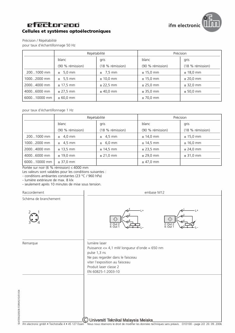
embase M12
lumière laserPuissance <= 4,1 mW longueur d'onde = 650 nmpulse 1,3 nsNe pas regarder dans le faisceauviter l'exposition au faisceauProduit laser classe 2EN 60825-1:2003-10
Précision / Répétabilitépour taux d'échantillonnage 50 Hz
pour taux d'échantillonnage 1 Hz
Raccordement
Schéma de branchement
Remarque
\DA
TEN
\200
\DB-
FORM
\O1D
/01/
04
ifm electronic gmbh • Teichstraße 4 • 45 127 Essen 20. 09. 2006
4
2 1
3
Cellules et systèmes optoélectroniques
Répétabilité Précision
blanc gris blanc gris
(90 % rémission) (18 % rémission) (90 % rémission) (18 % rémission)
200...1000 mm ± 5,0 mm ± 7,5 mm ± 15,0 mm ± 18,0 mm
1000...2000 mm ± 5,5 mm ± 10,0 mm ± 15,0 mm ± 20,0 mm
2000...4000 mm ± 17,5 mm ± 22,5 mm ± 25,0 mm ± 32,0 mm
4000...6000 mm ± 27,5 mm ± 40,0 mm ± 35,0 mm ± 50,0 mm
6000...10000 mm ± 60,0 mm ± 70,0 mm
Portée sur noir (6 % rémission) ≤ 4000 mmLes valeurs sont valables pour les conditions suivantes :- conditions ambiantes constantes (23 °C / 960 hPa)- lumière extérieure de max. 8 klx- seulement après 10 minutes de mise sous tension.
Nous nous réservons le droit de modifier les données techniques sans préavis. O1D100 - page 2/2
Répétabilité Précision
blanc gris blanc gris
(90 % rémission) (18 % rémission) (90 % rémission) (18 % rémission)
200...1000 mm ± 4,0 mm ± 4,5 mm ± 14,0 mm ± 15,0 mm
1000...2000 mm ± 4,5 mm ± 6,0 mm ± 14,5 mm ± 16,0 mm
2000...4000 mm ± 13,5 mm ± 14,5 mm ± 23,5 mm ± 24,0 mm
4000...6000 mm ± 19,0 mm ± 21,0 mm ± 29,0 mm ± 31,0 mm
6000...10000 mm ± 37,0 mm ± 47,0 mm
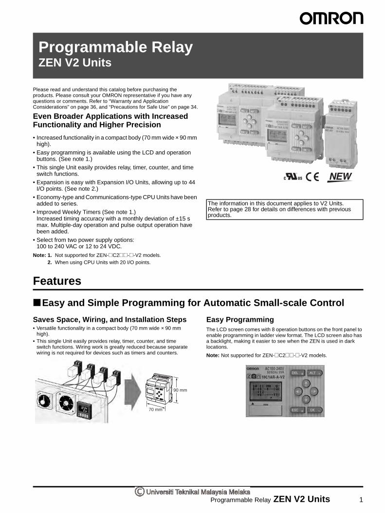
Programmable Relay ZEN V2 Units 1
Programmable RelayZEN V2 Units
Please read and understand this catalog before purchasing the products. Please consult your OMRON representative if you have any questions or comments. Refer to “Warranty and Application Considerations” on page 36, and “Precautions for Safe Use” on page 34.
Even Broader Applications with Increased Functionality and Higher Precision
• Increased functionality in a compact body (70 mm wide × 90 mm high).
• Easy programming is available using the LCD and operation buttons. (See note 1.)
• This single Unit easily provides relay, timer, counter, and time switch functions.
• Expansion is easy with Expansion I/O Units, allowing up to 44 I/O points. (See note 2.)
• Economy-type and Communications-type CPU Units have been added to series.
• Improved Weekly Timers (See note 1.)Increased timing accuracy with a monthly deviation of ±15 s max. Multiple-day operation and pulse output operation have been added.
• Select from two power supply options: 100 to 240 VAC or 12 to 24 VDC.
Note: 1. Not supported for ZEN-@C2@@-@-V2 models.2. When using CPU Units with 20 I/O points.
The information in this document applies to V2 Units. Refer to page 28 for details on differences with previous products.
Features
Easy and Simple Programming for Automatic Small-scale Control
Saves Space, Wiring, and Installation Steps• Versatile functionality in a compact body (70 mm wide × 90 mm
high).• This single Unit easily provides relay, timer, counter, and time
switch functions. Wiring work is greatly reduced because separate wiring is not required for devices such as timers and counters.
Easy ProgrammingThe LCD screen comes with 8 operation buttons on the front panel to enable programming in ladder view format. The LCD screen also has a backlight, making it easier to see when the ZEN is used in dark locations.
Note: Not supported for ZEN-@C2@@-@-V2 models.
90 mm
70 mm

2 Programmable Relay ZEN V2 Units
Flexible Expansion Enables Up to 44 I/O PointsUp to three Expansion I/O Units can be connected if there are not enough I/O points. Expansion I/O Units are only 35 mm wide.
Note: CPU Units with 10 I/O points can be expanded to 34 I/O points.Expansion I/O Units cannot be connected to Economy-type CPU Units.
Support Software with Simulation Function• Programs can be easily written, saved, and monitored by personal
computer.• Programs can be simulated on the personal computer without
connecting to the ZEN.
Note: For notebook computers that do not have an RS-232C serial port, connect the computer to the ZEN by connecting an OMRON CS1W-CIF31 USB-Serial Conversion Cable to the ZEN-CIF01 Connecting Cable.
Other Versatile Functions• Use of a Memory Cassette makes it easy to copy and save
programs.• Equipped with two analog input channels (CPU Units with DC
power supply only).• Password function ensures security. (See note.)• Multi-language display in six languages (English, Japanese,
German, French, Spanish, Italian). (See note.)• Display user-set messages or analog-converted values. (See note.)
Note: Not supported for ZEN-@C2@@-@-V2 models.
Enhanced Features of V2 CPU Units
Improved Weekly Timer and Calendar Timer FunctionsNote: Not supported for ZEN-@C2@@-@-V2 models.• The time precision has been increased.
Conventional model: 2-min difference/month ↓
-V2 models: ±15-s difference/month (at 25°C)• Multiple-day operation and pulse-output operation are now
possible.• These improved functions are convenient for time-controlled
applications such as lighting and air conditioning control.
Economy-type Added to the Series• Economy-type CPU Units with a more affordable price have been
added to the series, although Expansion I/O Units cannot be added.
12 to 24 VDC Line Voltage OperationOperation is now possible with 12 VDC.
Expansion I/O Units have been reduced to half-size (35 mm wide).
RS-485 Communications Model Added to SeriesProduction line conditions can be remotely monitored by monitoring the ZEN control status.
More Precise Analog InputConventional model: ± 10% FS → -V2 models: ± 1.5% FS DC power supply models are equipped with two analog inputs (0 to 10 V). There are four analog comparators. The increased precision makes it even easier to use the Unit in simple control applications with voltage, current, temperature, and other analog values.
8-digit Counter, 150-Hz Counter• An 8-digit counter and 8-digit comparator have been added.• The maximum count for DC power supply models is 150 Hz.
Twin-timer Operation AddedTwin-timer operation allows you to set ON and OFF times separately, greatly simplifying intermittent operation.
Lighting control Air conditioning control
Office
Production line

Programmable Relay ZEN V2 Units 3
Series Configuration
CPU UnitsPower supply voltage: 100 to 240 VAC, 12 to 24 VDC, Output: Relay, transistor output
With LCD display, operation buttons, and calendar/clock function LED type
10 I/O points
Standard LCD type Economy type Standard LCD type Economy typeCommunications type
20 I/O points 10 I/O points 20 I/O points
ZEN-10C1@ ZEN-10C3@ ZEN-10C4@ ZEN-20C1@ ZEN-20C3@
ZEN-10C2@
(10 I/O points)
ZEN-20C2@This CPU Unit has no LCD,operation buttons, or calendar/clock function.
Expansion I/O Units cannot be connected.
Expansion I/O Units cannot be connected.
RS-485 communications type.
Expansion I/O UnitsOnly 35-mm wide.4 input, 4 output points
Power Supply UnitSame shape and design as ZEN.24 VDC, 30 W
Support SoftwareAllows easy programming andoperation simulation.

4 Programmable Relay ZEN V2 Units
Model Number Structure
Model Number LegendNote: This model number legend includes combinations that are not available.
Please check “List of Models” for availability.
CPU Units
1. Number of I/O points10: 6 inputs and 4 outputs (See note.)20: 12 inputs and 8 outputs
2. Type classifier1: Standard LCD type with display2: LED type without display3: Economy type with display
(Expansion I/O Units cannot be connected.)4: Communications type with display
3. Input typeA: AC inputD: DC input
4. Output typeR: RelayT: Transistor
5. Supply voltageA: AC power supplyD: DC power supply
Note: The Communications-type CPU Unit has 6 inputs and 3 outputs.
Expansion I/O Units
1. Number of I/O points8: 4 inputs and 4 outputs
2. Unit version classifierE1: Can connect to V2 CPU Units (See note.)
3. Input typeA: AC inputD: DC input
4. Output typeR: RelayT: Transistor
Note: Use a ZEN-8E@@/-4E@ to connect to pre-V1 and V1 CPU Units.
ZEN-@C@@@-@-V21 2 3 4 5
ZEN-8E1@@1 2 3 4
This data sheet is provided as a guideline for selecting products. Be sure to refer to the following user manuals for application precautions and other information required for operation before attempting to use the product.
ZEN Operation Manual (Cat. No. Z211)
ZEN Communications Manual (Cat. No. Z212)
ZEN Support Software Operation Manual (Cat. No. Z184-E1-03)
The PDF versions of these manuals can be downloaded from the following website.
ZEN Website http://www.zen.omron.co.jp/eng/index.html

Programmable Relay ZEN V2 Units 5
Ordering Information
List of Models
CPU Units and Expansion I/O Units
Note: 1. Programming is not possible using only the CPU in the LED-type CPU Unit. ZEN Support Software or a Memory Cassette is required.2. Cannot be connected to pre-V1 and V1 CPU Units.3. The ZEN-8E1AR cannot be connected to a CPU Unit with DC power supply.
Power Supply Unit
Note: Refer to the ZEN-PA03024 Datasheet (Cat. No. L103) for detailed specifications.
Unit Name No. of I/O
points
LCD display
Power supply voltage
Inputs Outputs Buttons, calendar, and clock
Analog input
Model
CPU Units
Standard LCD type
10 Yes 100 to 240 VAC 6 100 to 240 VAC 4 Relays Yes No ZEN-10C1AR-A-V2
12 to 24 VDC 12 to 24 VDC Yes ZEN-10C1DR-D-V2
Transistors ZEN-10C1DT-D-V2
20 100 to 240 VAC 12 100 to 240 VAC 8 Relays No ZEN-20C1AR-A-V2
12 to 24 VDC 12 to 24 VDC Yes ZEN-20C1DR-D-V2
Transistors ZEN-20C1DT-D-V2
LED type without display(See note 1.)
10 No 100 to 240 VAC 6 100 to 240 VAC 4 Relays No No ZEN-10C2AR-A-V2
12 to 24 VDC 12 to 24 VDC Yes ZEN-10C2DR-D-V2
Transistors ZEN-10C2DT-D-V2
20 100 to 240 VAC 12 100 to 240V AC 8 Relays No ZEN-20C2AR-A-V2
12 to 24 VDC 12 to 24 VDC Yes ZEN-20C2DR-D-V2
Transistors ZEN-20C2DT-D-V2
Economy type (Expansion I/O Units cannot be connected)
10 Yes 100 to 240 VAC 6 100 to 240 VAC 4 Relays Yes No ZEN-10C3AR-A-V2
12 to 24 VDC 12 to 24 VDC Yes ZEN-10C3DR-D-V2
20 100 to 240 VAC 12 100 to 240 VAC 8 Relays No ZEN-20C3AR-A-V2
12 to 24 VDC 12 to 24 VDC Yes ZEN-20C3DR-D-V2
Communica-tions type
10 100 to 240 VAC 6 100 to 240 VAC 3 Relays No ZEN-10C4AR-A-V2
12 to 24 VDC 12 to 24 VDC Yes ZEN-10C4DR-D-V2
ZEN Kit Set containing CPU Unit (ZEN-10C1AR-A-V2), Connecting Cable, ZEN Support Software, and manual. ZEN-KIT01-EV4
Set containing CPU Unit (ZEN-10C1DR-D-V2), Connecting Cable, ZEN Support Software, and manual. ZEN-KIT02-EV4
Expansion I/O Units 8 --- 100 to 240 VAC 4 100 to 240 VAC 4 Relays --- ZEN-8E1AR (See notes 2, 3.)
12 to 24 VDC 12 to 24 VDC ZEN-8E1DR (See note 2.)
--- Transistors ZEN-8E1DT (See note 2.)
Power ratings Input voltage Output voltage Output current Model
30 W 100 to 240 VAC 24 VDC 1.3 A ZEN-PA03024
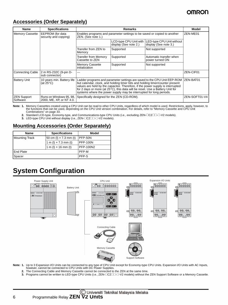
6 Programmable Relay ZEN V2 Units
Accessories (Order Separately)
Note: 1. Memory Cassettes created using a CPU Unit can be read to other CPU Units, regardless of which model is used. Restrictions, apply, however, to the functions that can be used, depending on the CPU Unit version combination. For details, refer to “Memory Cassette and CPU Unit Combinations” on page 33.
2. Standard LCD-type, Economy-type, and Communications-type CPU Units (i.e., excluding ZEN-@C2@@-@-V2 models).3. LED-type CPU Unit without display (i.e., ZEN-@C2@@-@-V2 models).
Mounting Accessories (Order Separately)
System Configuration
Note: 1. Up to 3 Expansion I/O Units can be connected to any type of CPU Unit except for Economy-type CPU Units. Expansion I/O Units with AC Inputs, however, cannot be connected to CPU Units with DC Power Supplies.
2. The Connecting Cable and Memory Cassette cannot be connected to the ZEN at the same time.3. Programs cannot be written to LED-type CPU Units (i.e., ZEN-@C2@@-@-V2 models) without the ZEN Support Software or a Memory Cassette.
Name Specifications Remarks Model
Memory Cassette EEPROM (for data security and copying)
Enables programs and parameter settings to be saved or copied to another ZEN. (See note 1.)
ZEN-ME01
LCD-type CPU Unit with display (See note 2.)
LED-type CPU Unit without display (See note 3.)
Transfer from ZEN to Memory
Supported Not supported
Transfer from Memory Cassette to ZEN
Supported Automatic transfer when power turned ON
Memory Cassette initialization
Supported Not supported
Connecting Cable 2 m RS-232C (9-pin D-sub connector)
--- ZEN-CIF01
Battery Unit 10 years min. Battery life (at 25°C)
Ladder programs and parameter settings are saved to the CPU Unit EEP-ROM but calendar, clock, and holding timer bits and holding timer/counter present values are held by the capacitor. Therefore, if the power supply is interrupted for 2 days or more (at 25°C), this data will be reset. Use a Battery Unit for systems where the power supply may be interrupted for long periods.
ZEN-BAT01
ZEN Support Software
Runs on Windows 95, 98, 2000, ME, XP, or NT 4.0.
Specifically designed for the ZEN (CD-ROM). ZEN-SOFT01-V4
Name Specifications Model
Mounting Track 50 cm (l) × 7.3 mm (t) PFP-50N
1 m (l) × 7.3 mm (t) PFP-100N
1 m (l) × 16 mm (t) PFP-100N2
End Plate PFP-M
Spacer PFP-S
CPU UnitPower Supply Unit
Connecting Cable
Support Software
Memory Cassette
Battery Unit
Expansion I/O Units
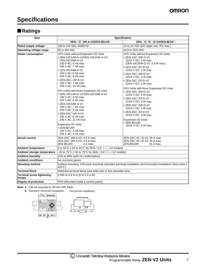
Programmable Relay ZEN V2 Units 7
Specifications
Ratings
Note: 1. Can be mounted to 35-mm DIN Track.2.
Item Specification
ZEN-@C@AR-A-V2/ZEN-8E1AR ZEN-@C@D@-D-V2/ZEN-8E1D@Rated supply voltage 100 to 240 VAC, 50/60 Hz 12 to 24 VDC (DC ripple rate: 5% max.)
Operating voltage range 85 to 264 VAC 10.8 to 28.8 VDC
Power consumption CPU Units without Expansion I/O Units • ZEN-10C1AR-A-V2/ZEN-10C2AR-A-V2/
ZEN-10C3AR-A-V2100 V AC: 5 VA max.240 V AC: 7 VA max.
• ZEN-10C4AR-A-V2100 V AC: 6 VA max.240 V AC: 8 VA max.
• ZEN-20C@AR-A-V2100 V AC: 7 VA max.240 V AC: 10 VA max.
CPU Units with three Expansion I/O Units• ZEN-10C1AR-A-V2/ZEN-10C2AR-A-V2
100 V AC: 6 VA max.240 V AC: 8 VA max.
• ZEN-10C4AR-A-V2100 V AC: 7 VA max.240 V AC: 9 VA max.
• ZEN-20C@AR-A-V2100 V AC: 8 VA max.240 V AC: 11 VA max.
Expansion I/O Units• ZEN-8E1AR
100 V AC: 3 VA max.240 V AC: 4 VA max.
CPU Units without Expansion I/O Units• ZEN-10C@DR-D-V2
12/24 V DC: 3 W max.(ZEN-10C3DR-D-V2: 2.8 W max.)
• ZEN-10C@DT-D-V2 12/24 V DC: 2 W max.
• ZEN-20C@DR-D-V2 12/24 V DC: 4 W max.
• ZEN-20C@DT-D-V2 12/24 V DC: 2 W max.
CPU Units with three Expansion I/O Units• ZEN-10C@DR-D-V2
12/24 V DC: 4 W max.• ZEN-10C@DT-D-V2
12/24 V DC: 3 W max.• ZEN-20C@DR-D-V2
12/24 V DC: 5 W max.• ZEN-20C@DT-D-V2
12/24 V DC: 3 W max.
Expansion I/O Units• ZEN-8E1DR
12/24 V DC: 2 W max.
Inrush current ZEN-10C@AR-A-V2: 4.5 A max.ZEN-20C@AR-A-V2: 4.5 A max.ZEN-8E1AR: 4 A max.
ZEN-10C@D@-D-V2: 30 A max.ZEN-20C@D@-D-V2: 30 A max.ZEN-8E1DR: 15 A max.
Ambient temperature 0 to 55°C (−25 to 55°C for ZEN-@C2@@-@-V2 models)
Ambient storage temperature −20 to 75°C (−40 to 75°C for ZEN-@C2@@-@-V2 models)
Ambient humidity 10% to 90% (with no condensation)
Ambient conditions No corrosive gases
Mounting method Surface mounting, DIN track mounting (standard (vertical) installation and horizontal installation) (See notes 1 and 2.)
Terminal block Solid-line terminal block (use solid wire or fine-stranded wire)
Terminal screw tightening torque
0.565 to 0.6 N·m (5 to 5.3 in-lb)
Degree of protection IP20 (Mounted inside a control panel)
Standard (Vertical) installation Horizontal installation

8 Programmable Relay ZEN V2 Units
Characteristics
Note: 1. Up to 34 points for CPU Units with 10 I/O points. With Communications-type CPU Units, however, the CPU Unit has 6 inputs and 3 outputs, for a maximum of 33 I/O points.
2. Not provided for LED-type CPU Unit without display (i.e., ZEN-@C2@@-@-V2 models).
Communications Specifications (Communications-type CPU Units)
Item Specification
Control method Stored program control
I/O control method Cyclic scan
Programming language Ladder diagram
Program capacity 96 lines (3 input conditions and 1 output per line)
Max. No. of control I/O points 44 points (See note 1.)CPU Units with 20 I/O points: 12 inputs and 8 outputsExpansion I/O Units: 4 inputs and 4 outputs each, up to 3 Units.
LCD display (See note 2.) 12 characters × 4 lines, with backlight
Operation buttons (See note 2.) 8 (4 cursor buttons and 4 operation buttons)
User program backup Internal EEPROM, Memory Cassette (optional)
Power interruption hold Internal holding bit status, holding timer/counter present values, calendar and clock (year, month, day of month, day of week, time)• Super capacitor backup time:2 days min. (25°C)• Life of optional battery: 10 years min. (25°C)
Calendar and clock function (See note 2.)
Accuracy: ±15 s/month (at 25°C)
Timer accuracy 0.01 s unit: −0.05% −10 ms max. (rate for set value)min/s unit: −0.05% −1 s max. (rate for set value)h/min unit: −0.05% −1 min max. (rate for set value)
Maximum counting speed 150 Hz: 8-Digit counter (F) set to high-speed operations (CPU Units with DC power supplies only) (The counting speed may be less than 150 Hz depending on the cycle time of the program. See page 21.)
Insulation resistance 20 MΩ (at 500 VDC) min.:Between power supply terminals and all output terminals. Between terminals of different output circuits.Between all terminals of CPU Unit and all terminals of Expansion I/O Unit.
Insulation • Reinforced insulationBetween power supply or input terminals and output terminals. Between terminals of different output circuits. Between all terminals of CPU Unit and all terminals of Expansion I/O Unit.
• No separationBetween power supply and input terminals of the same unit.Between power supply terminals of CPU Unit and computer connector, Battery Unit connector, or all Expansion Unit connectors (all interfaces are live parts).
Dielectric strength 2,300 VAC, 50/60 Hz for 1 min (leakage current 1 mA max.): Between power supply terminals and all output terminals. Between terminals of different output circuit.Between all terminals of CPU Unit and all terminals of Expansion I/O Unit.
Vibration resistance Conforms to IEC60068-2-6, 5 to 9 Hz with 3.5-mm single amplitude, 9 to 150 Hz acceleration 9.8 m/s2, 10 sweeps each in X, Y, and Z directions (1 octave/min)
Shock resistance Conforms to IEC60068-2-27, 147 m/s2, 3 times each in X, Y, and Z directions.
Weight CPU Unit with 10 I/O points: Approx. 300 g max.CPU Unit with 20 I/O points: Approx. 350 g max.Expansion I/O Unit: Approx. 120 g max.
Item ZEN-10C4@R-@-V2
Communications RS-485 (two-wire, half duplex)
Synchronization method Start-stop synchronization
Baud rate 4800, 9600, or 19200 bps
Transmission code ASCII
Data bit length 7 or 8 bits
Stop bit length 1 or 2 bits
Error detection Vertical parity (none, even, odd), Block check character (BCC)
Flow control None
Interface RS-485
Retry function None
Node number 0 to 99 (default: 1), XX (broadcasting)

Programmable Relay ZEN V2 Units 9
Approved Standards
Note: EMC conforms to EN 61131-2 clause 8 except in the following cases.
• When Expansion I/O Units with DC inputs are connected to a CPU Unit with an AC power supply, the burst immunity between power supplies will be 1 kv.
• When the signal wire for transistor outputs exceeds 10 m, the surge immunity of DC output signal lines will not conform.
Input Specifications
CPU Units
AC Inputs (Not Isolated)
Note: Can be selected using the filter settings.
DC Inputs: I0 to I3 for Units with 10 I/O points, I0 to I9 for Units with 20 I/O Points (Not Isolated)
Note: Can be selected using the input filter settings, except when I0 is being used for an 8-digit counter with a high-speed input.
Item Specification
Safety standards cULus: UL508/CSA C22.2 No.142 Class I Div2Conforms to EN/IEC 61131-2 clause 11, excluding 11.7.2.2 (Overvoltage category 2 and Pollution degree II conforms to IEC 60664-1)
EMC(See note.)
Radiation Field Emission CISPR11 Class A, Group 1Noise Terminal Voltage Emission CISPR11 Class A, Group 1
Electrostatic Discharge Immunity IEC61000-4-2 In air: 8 kV, In contact: 6 kVElectromagnetic Field Immunity IEC61000-4-3 10 V/mElectrical Fast Transient/Burst Immunity IEC61000-4-4 Power line
AC I/O: 2 kVDC I/O: 1 kV
Surge Immunity IEC61000-4-5 Normal NoiseAC power supply, AC I/O: 1 kVDC power supply, DC I/O: 0.5 kV
Common NoiseAC power supply, AC I/O: 2 kVDC power supply: 1 kVDC I/O: 0.5 kV
Immunity to Conducted Disturbances Induced by Radio-frequency FieldsIEC61000-4-6 3 V
Momentary Power Interruption Immunity IEC61131-2 CPU Units with AC Power Supplies:10 ms max.CPU Units with DC Power Supplies: 2 ms max. (level: PS1)
Item Specifications Circuit drawing
Input voltage 100 to 240 VAC +10%, −15%, 50/60 Hz
Input impedance 680 kΩInput current 0.15 mA/100 VAC, 0.35 mA/240 VAC
ON voltage 80 VAC min.
OFF voltage 25 VAC max.
ON response time 50 ms or 70 ms at 100 VAC (See note.)100 ms or 120 ms at 240 VAC (See note.)OFF response time
Item Specifications Circuit drawing
Input voltage 12 to 24 VDC +20%, −10%
Input impedance 5.3 kΩInput current 4.5 mA (typ.)/24 VDC
ON voltage 8 VDC min.
OFF voltage 5 VDC max.
ON response time 15 ms or 50 ms (See note.)
OFF response time
100 to 240 VACN
L
IN
IN 330 kΩ 300 kΩ
51 kΩ Internal circuit
12 to 24 VDC
5.1 kΩ 1.8 kΩIN
IN
COM
Internal circuit
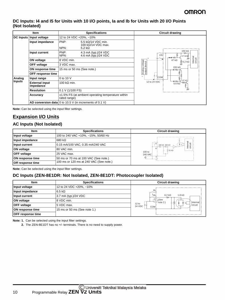
10 Programmable Relay ZEN V2 Units
DC Inputs: I4 and I5 for Units with 10 I/O points, Ia and Ib for Units with 20 I/O Points (Not Isolated)
Note: Can be selected using the input filter settings.
Expansion I/O UnitsAC Inputs (Not Isolated)
Note: Can be selected using the input filter settings.
DC Inputs (ZEN-8E1DR: Not Isolated, ZEN-8E1DT: Photocoupler Isolated)
Note: 1. Can be selected using the input filter settings.2. The ZEN-8E1DT has no +/- terminals. There is no need to supply power.
Item Specifications Circuit drawing
DC Inputs Input voltage 12 to 24 VDC +20%, −10%
Input impedance PNP: 5.5 kΩ/14 VDC min.100 kΩ/14 VDC max.
NPN: 5.2 kΩInput current PNP: 4.3 mA (typ.)/24 VDC
NPN: 4.6 mA (typ.)/24 VDC
ON voltage 8 VDC min.
OFF voltage 3 VDC max.
ON response time 15 ms or 50 ms (See note.)
OFF response time
Analog Inputs
Input range 0 to 10 V
External input impedance
100 kΩ min.
Resolution 0.1 V (1/100 FS)
Accuracy ±1.5% FS (at ambient operating temperature within rated range)
AD conversion data 0 to 10.5 V (in increments of 0.1 V)
12 to 24 VDC
IN
COM
6.2 kΩ
220 kΩ
5.6 kΩ
150 kΩ
47 kΩ
47 kΩ
27 kΩ
−
+
Inte
rnal
ci
rcui
t
Ana
log
volta
ge
outp
ut d
evic
e
Item Specifications Circuit drawing
Input voltage 100 to 240 VAC +10%, −15%, 50/60 Hz
Input impedance 680 kΩInput current 0.15 mA/100 VAC, 0.35 mA/240 VAC
ON voltage 80 VAC min.
OFF voltage 25 VAC max.
ON response time 50 ms or 70 ms at 100 VAC (See note.)100 ms or 120 ms at 240 VAC (See note.)Off response time
Item Specifications Circuit drawing
Input voltage 12 to 24 VDC +20%, −10%
Input impedance 6.5 kΩInput current 3.7 mA (typ.)/24 VDC
ON voltage 8 VDC min.
OFF voltage 5 VDC max.
ON response time 15 ms or 50 ms (See note 1.)
OFF response time
IN
IN
100 to 240 VAC
N
L
330 kΩ
51 kΩ
300 kΩ
Inte
rnal
circ
uit
12 to 24 VDC
6.2 kΩ
(See note 2.)
1.8 kΩ
IN
IN
±
COM
Internal circuit
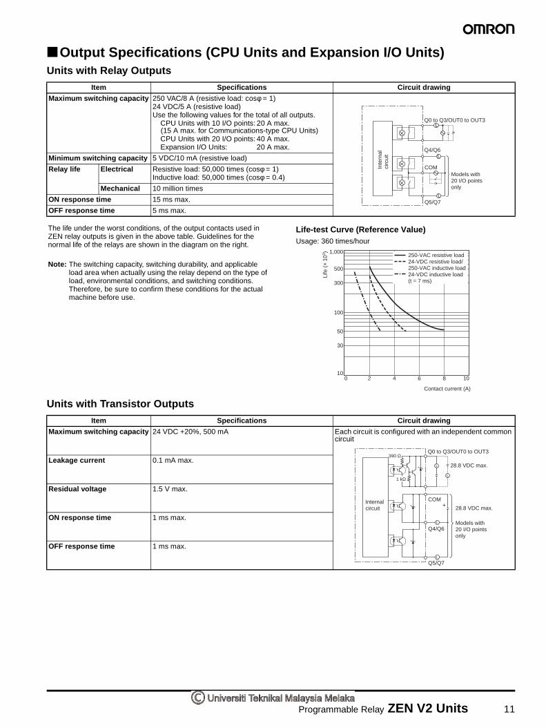
Programmable Relay ZEN V2 Units 11
Output Specifications (CPU Units and Expansion I/O Units)Units with Relay Outputs
Units with Transistor Outputs
Item Specifications Circuit drawing
Maximum switching capacity 250 VAC/8 A (resistive load: cosφ = 1)24 VDC/5 A (resistive load)Use the following values for the total of all outputs.
CPU Units with 10 I/O points: 20 A max. (15 A max. for Communications-type CPU Units)CPU Units with 20 I/O points: 40 A max.Expansion I/O Units: 20 A max.
Minimum switching capacity 5 VDC/10 mA (resistive load)
Relay life Electrical Resistive load: 50,000 times (cosφ = 1)Inductive load: 50,000 times (cosφ = 0.4)
Mechanical 10 million times
ON response time 15 ms max.
OFF response time 5 ms max.
Item Specifications Circuit drawing
Maximum switching capacity 24 VDC +20%, 500 mA Each circuit is configured with an independent common circuit
Leakage current 0.1 mA max.
Residual voltage 1.5 V max.
ON response time 1 ms max.
OFF response time 1 ms max.
Q0 to Q3/OUT0 to OUT3
Q4/Q6
COM
Q5/Q7
Models with 20 I/O points only
L
L
L
Inte
rnal
ci
rcui
t
1,000
300
100
100 2 4 6 8 10
Contact current (A)
30
50
500
250-VAC resistive load24-VDC resistive load/250-VAC inductive load24-VDC inductive load (t = 7 ms)
Life
(×
103 )
The life under the worst conditions, of the output contacts used in ZEN relay outputs is given in the above table. Guidelines for the normal life of the relays are shown in the diagram on the right.
Life-test Curve (Reference Value)Usage: 360 times/hour
Note: The switching capacity, switching durability, and applicable load area when actually using the relay depend on the type of load, environmental conditions, and switching conditions. Therefore, be sure to confirm these conditions for the actual machine before use.
Q0 to Q3/OUT0 to OUT3
Models with 20 I/O points only
390 Ω
COM
Q4/Q6
Q5/Q7
28.8 VDC max.
28.8 VDC max.
L
L
L
L
1 kΩ
+Internal circuit
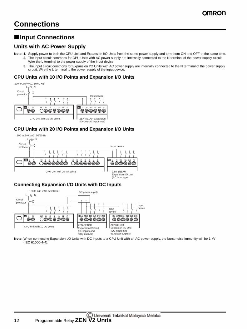
12 Programmable Relay ZEN V2 Units
Connections
Input ConnectionsUnits with AC Power SupplyNote: 1. Supply power to both the CPU Unit and Expansion I/O Units from the same power supply and turn them ON and OFF at the same time.
2. The input circuit commons for CPU Units with AC power supply are internally connected to the N terminal of the power supply circuit. Wire the L terminal to the power supply of the input device.
3. The input circuit commons for Expansion I/O Units with AC power supply are internally connected to the N terminal of the power supply circuit. Wire the L terminal to the power supply of the input device.
CPU Units with 10 I/O Points and Expansion I/O Units
CPU Units with 20 I/O Points and Expansion I/O Units
Connecting Expansion I/O Units with DC Inputs
Note: When connecting Expansion I/O Units with DC inputs to a CPU Unit with an AC power supply, the burst noise immunity will be 1 kV (IEC 61000-4-4).
L N IN0 IN1 IN2 IN3L N NC I0 I1 I2 I3 I4 I5
100 to 240 VAC, 50/60 HzL N
Circuit protector
Input device
CPU Unit with 10 I/O points ZEN-8E1AR Expansion I/O Unit (AC input type)
L N NC I0 I1 I2 I3 I4 I5 NC I6 I7 I8 I9 Ia Ib L N IN0 IN1 IN2 IN3
L N
Circuit protector
CPU Unit with 20 I/O points ZEN-8E1AR Expansion I/O Unit (AC input type)
100 to 240 VAC, 50/60 Hz
Input device
L N NC I0 I1 I2 I3 I4 I5 COM IN0 IN1 IN2 IN3 COM IN0 IN1 IN2 IN3
L N
CPU Unit with 10 I/O points
100 to 240 VAC, 50/60 Hz DC power supply
Circuit protector
Input device
ZEN-8E1DR Expansion I/O Unit (DC inputs and relay outputs)
Input device
ZEN-8E1DT Expansion I/O Unit (DC inputs and transistor outputs)
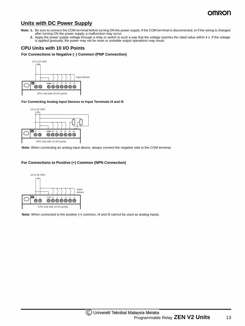
Programmable Relay ZEN V2 Units 13
Units with DC Power SupplyNote: 1. Be sure to connect the COM terminal before turning ON the power supply. If the COM terminal is disconnected, or if the wiring is changed
after turning ON the power supply, a malfunction may occur.2. Apply the power supply voltage through a relay or switch in such a way that the voltage reaches the rated value within 4 s. If the voltage
is applied gradually, the power may not be reset or unstable output operations may result.
CPU Units with 10 I/O PointsFor Connections to Negative (−) Common (PNP Connection)
COM
CPU Unit with 10 I/O points
Input device
12 to 24 VDC
For Connecting Analog Input Devices to Input Terminals I4 and I5
CPU Unit with 10 I/O points
12 to 24 VDC
COM I0 I1 I2 I3 I4 I5
For Connections to Positive (+) Common (NPN Connection)
COM I0 I1 I2 I3 I4 I5+ −
12 to 24 VDC
CPU Unit with 10 I/O points
Input device
Note: When connected to the positive (+) common, I4 and I5 cannot be used as analog inputs.
Note: When connecting an analog input device, always connect the negative side to the COM terminal.


