Slope failures on the flanks of the western Canary Islandsjacdev/pdf/masson02.pdf · Slope failures...
35
Ž . Earth-Science Reviews 57 2002 1–35 www.elsevier.comrlocaterearscirev Slope failures on the flanks of the western Canary Islands D.G. Masson a, ) , A.B. Watts b , M.J.R. Gee a,b , R. Urgeles c , N.C. Mitchell b,d , T.P. Le Bas a , M. Canals c a Southampton Oceanography Centre, Empress Dock, European Way, Southampton SO14 3ZH, UK b Department of Earth Sciences, UniÕersity of Oxford, Parks Road, Oxford OX1 3PR, UK c Departamento d’Estratigrafia i Paleontologia, Facultat de Geologia, UniÕersitat de Barcelona, Campus de Pedralbes, E-08071 Barcelona, Spain d Department of Earth Sciences, Cardiff UniÕersity, PO Box 914, Cardiff CF10 3YE, UK Received 7 June 2000; accepted 17 May 2001 Abstract Landslides have been a key process in the evolution of the western Canary Islands. The younger and more volcanically active Canary Islands, El Hierro, La Palma and Tenerife, show the clearest evidence of recent landslide activity. The evidence includes landslide scars on the island flanks, debris deposits on the lower island slopes, and volcaniclastic turbidites on the floor of the adjacent ocean basins. At least 14 large landslides have occurred on the flanks of the El Hierro, La Palma and Tenerife, the majority of these in the last 1 million years, with the youngest, on the northwest flank of El Hierro, as recent as 15 thousand years in age. Older landslides undoubtedly occurred, but are difficult to quantify because the evidence is buried beneath younger volcanic rocks and sediments. Landslides on the Canary Island flanks can be categorised as debris avalanches, slumps or debris flows. Debris avalanches are long runout catastrophic failures which typically affect only the superficial part of the island volcanic sequence, up to a maximum thickness of 1 to 2 km. They are the commonest type of landslide mapped. In contrast, slumps move short distances and are deep-rooted landslides which may affect the entire thickness of the volcanic edifice. Debris flows are defined as landslides which primarily affect the sedimentary cover of the submarine island flanks. Some landslides are complex events involving more than one of the above end-member processes. Individual debris avalanches have volumes in the range of 50–500 km 3 , cover several thousand km 2 of seafloor, and have runout distances of up to 130 km from source. Overall, debris avalanche deposits account for about 10% of the total volcanic edifices of the small, relatively young islands of El Hierro and La Palma. Some parameters, such as deposit volumes and landslide ages, are difficult to quantify. The key characteristics of debris avalanches include a relatively narrow headwall and chute above 3000 m water depth on the island flanks, broadening into a depositional lobe below 3000 m. Debris avalanche deposits have a typically blocky morphology, with individual blocks up to a kilometre or more in diameter. However, considerable variation exists between different avalanche deposits. At one extreme, the El Golfo debris avalanche on El Hierro has few large blocks scattered randomly across the avalanche surface. At the other, Icod on the north flank of Tenerife has much more numerous but smaller blocks over most of its surface, with a few very large blocks confined to the Ž . margins of the deposit. Icod also exhibits flow structures longitudinal shears and pressure ridges that are absent in El Golfo. The primary controls on the block structure and distribution are inferred to be related to the nature of the landslide material and to flow processes. Observations in experimental debris flows show that the differences between the El Golfo ) Corresponding author. Tel.: q 44-1703-596568; fax: q 44-1703-596554. Ž . E-mail address: [email protected] D.G. Masson . 0012-8252r02r$ - see front matter q 2002 Elsevier Science B.V. All rights reserved. Ž . PII: S0012-8252 01 00069-1
Transcript of Slope failures on the flanks of the western Canary Islandsjacdev/pdf/masson02.pdf · Slope failures...

Ž .Earth-Science Reviews 57 2002 1–35www.elsevier.comrlocaterearscirev
Slope failures on the flanks of the western Canary Islands
D.G. Masson a,), A.B. Watts b, M.J.R. Gee a,b, R. Urgeles c, N.C. Mitchell b,d,T.P. Le Bas a, M. Canals c
a Southampton Oceanography Centre, Empress Dock, European Way, Southampton SO14 3ZH, UKb Department of Earth Sciences, UniÕersity of Oxford, Parks Road, Oxford OX1 3PR, UK
c Departamento d’Estratigrafia i Paleontologia, Facultat de Geologia, UniÕersitat de Barcelona, Campus de Pedralbes,E-08071 Barcelona, Spain
d Department of Earth Sciences, Cardiff UniÕersity, PO Box 914, Cardiff CF10 3YE, UK
Received 7 June 2000; accepted 17 May 2001
Abstract
Landslides have been a key process in the evolution of the western Canary Islands. The younger and more volcanicallyactive Canary Islands, El Hierro, La Palma and Tenerife, show the clearest evidence of recent landslide activity. Theevidence includes landslide scars on the island flanks, debris deposits on the lower island slopes, and volcaniclastic turbiditeson the floor of the adjacent ocean basins. At least 14 large landslides have occurred on the flanks of the El Hierro, La Palmaand Tenerife, the majority of these in the last 1 million years, with the youngest, on the northwest flank of El Hierro, asrecent as 15 thousand years in age. Older landslides undoubtedly occurred, but are difficult to quantify because the evidenceis buried beneath younger volcanic rocks and sediments. Landslides on the Canary Island flanks can be categorised as debrisavalanches, slumps or debris flows. Debris avalanches are long runout catastrophic failures which typically affect only thesuperficial part of the island volcanic sequence, up to a maximum thickness of 1 to 2 km. They are the commonest type oflandslide mapped. In contrast, slumps move short distances and are deep-rooted landslides which may affect the entirethickness of the volcanic edifice. Debris flows are defined as landslides which primarily affect the sedimentary cover of thesubmarine island flanks. Some landslides are complex events involving more than one of the above end-member processes.
Individual debris avalanches have volumes in the range of 50–500 km3, cover several thousand km2 of seafloor, andhave runout distances of up to 130 km from source. Overall, debris avalanche deposits account for about 10% of the totalvolcanic edifices of the small, relatively young islands of El Hierro and La Palma. Some parameters, such as depositvolumes and landslide ages, are difficult to quantify. The key characteristics of debris avalanches include a relatively narrowheadwall and chute above 3000 m water depth on the island flanks, broadening into a depositional lobe below 3000 m.Debris avalanche deposits have a typically blocky morphology, with individual blocks up to a kilometre or more in diameter.However, considerable variation exists between different avalanche deposits. At one extreme, the El Golfo debris avalancheon El Hierro has few large blocks scattered randomly across the avalanche surface. At the other, Icod on the north flank ofTenerife has much more numerous but smaller blocks over most of its surface, with a few very large blocks confined to the
Ž .margins of the deposit. Icod also exhibits flow structures longitudinal shears and pressure ridges that are absent in ElGolfo. The primary controls on the block structure and distribution are inferred to be related to the nature of the landslidematerial and to flow processes. Observations in experimental debris flows show that the differences between the El Golfo
) Corresponding author. Tel.: q44-1703-596568; fax: q44-1703-596554.Ž .E-mail address: [email protected] D.G. Masson .
0012-8252r02r$ - see front matter q 2002 Elsevier Science B.V. All rights reserved.Ž .PII: S0012-8252 01 00069-1

( )D.G. Masson et al.rEarth-Science ReÕiews 57 2002 1–352
and Icod landslide deposits are probably controlled by the greater proportion of fine grained material in the Icod landslide.This, in turn, relates to the nature of the failed volcanic rocks, which are almost entirely basalt on El Hierro but include amuch greater proportion of pyroclastic deposits on Tenerife.
Landslide occurrence appears to be primarily controlled by the locations of volcanic rift zones on the islands, withlandslides propagating perpendicular to the rift orientation. However, this does not explain the uneven distribution oflandslides on some islands which seems to indicate that unstable flanks are a ‘weakness’ that can be carried forward duringisland development. This may occur because certain island flanks are steeper, extend to greater water depths or are lessbuttressed by the surrounding topography, and because volcanic production following a landslide my be concentrated in thelandslide scar, thus focussing subsequent landslide potential in this area. Landslides are primarily a result of volcanicconstruction to a point where the mass of volcanic products fails under its own weight. Although the actual triggering factorsare poorly understood, they may include or be influenced by dyke intrusion, pore pressure changes related to intrusion,seismicity or sealevelrclimate changes. A possible relationship between caldera collapse and landsliding on Tenerife is not,in our interpretation, supported by the available evidence. q 2002 Elsevier Science B.V. All rights reserved.
Keywords: Canary Islands; Landslides; Debris avalanches; Slumps; Debris flows
1. Introduction
It is now firmly established that large-scale lands-liding is a key processes in the evolution of oceanicislands. Detailed studies of landslides have been
Žcarried out around the Hawaiian Islands Lipman et.al., 1988; Moore et al., 1989, 1994 , Reunion
ŽCochonat et al., 1990; Labazuy, 1996; Ollier et al.,. Ž1998 and the Canary Islands Holcomb and Searle,
1991; Krastel et al., 2001; Masson, 1996; Masson etal., 1998; Teide Group, 1997; Urgeles et al., 1997,
.1999; Watts and Masson, 1995 . Some of the clear-est evidence for landsliding, in the form of large
fields of blocky landslide deposits, has been reportedoffshore. Landslide deposits can be transported sev-eral hundred kilometres and cover many hundreds ofkm2 of seafloor on the submarine island flanks.Individual landslides can involve up to a few thou-sand km3 of material, but more typically are a fewhundred km3 in volume. Onshore, landslide head-walls are typically expressed as arcuate embayments
Žand steep cliffs Cantagrel et al., 1999; Navarro and.Coello, 1989; Ollier et al., 1998; Ridley, 1971 .
In the Canary Islands, the relatively recent discov-Žery of landslide deposits offshore Holcomb and
Searle, 1991; Masson, 1996; Watts and Masson,
Fig. 1. Map showing location of the Canary Islands and areas where landslide deposits have been mapped.

( )D.G. Masson et al.rEarth-Science ReÕiews 57 2002 1–35 3
.1995 confirms earlier controversial interpretationsŽbased on the onshore geology Bravo, 1962; Navarro
.and Coello, 1989 . Prior to the study presented here,all the offshore studies have concentrated on areas ofisland flank downslope of suspected subaerial land-slide scars, in particular the Orotava, Icod and Guimarvalleys on Tenerife, the Taburiente CalderarCumbreNueva Arc on La Palma, and the El Golfo embay-
Žment on El Hierro Holcomb and Searle, 1991;Masson, 1996; Masson et al., 1998; Teide Group,1997; Urgeles et al., 1997, 1999; Watts and Masson,
.1995 . Here we present the results of a more compre-hensive study of flank collapse processes on Tener-ife, La Palmas and El Hierro. The paper is partly areview and summary of previously published data,but also draws on a considerable volume of new
Fig. 2. Summary of data coverage around the islands of El Hierro, La Palma and Tenerife. EM12 swath bathymetry data was collected onŽ . Ž . Ž .RRS Charles Darwin cruises 82 1993 and 108 1997 and on the ‘Crescent-94’ cruise of the BIO Hesperides 1994 . TOBI sidescan sonar
Ž .data was collected on RRS Discovery cruise 205 1993 and RRS Charles Darwin cruise 108. Multichannel seismic reflection profiles wereŽ .collected on RRS Charles Darwin cruises 82 and on a cruise of the Dutch research vessel Zirfaea 1994 , and single channel data were
Ž .collected on RRS Charles Darwin cruise 108, RRS Discovery cruise 188 1989 and the ‘Crescent-94’ cruise of the BIO Hesperides. Allcruises collected 3.5 kHz profiles.

( )D.G. Masson et al.rEarth-Science ReÕiews 57 2002 1–354
material. Much of the discussion, particularly thesection on flow processes, is based on a new compar-ison between landslides on the different islands.
A Simrad EM12 multibeam system was used tomap the submarine morphology and backscattercharacteristics of large areas of island flank. Thesedata clearly distinguish between unfailed islandslopes and those affected by landsliding processes.High resolution, deep-towed, sidescan sonar data,acquired with the TOBI 30 kHz system, was used toexamine the surface structure of landslide deposits ingreater detail, to gain a better understanding of lands-
liding processes. Our results show that landsliding onthe flanks of the islands is more widespread thanpreviously supposed, and that landslide processes areboth variable and complex. At least 14 individuallandslides have been identified.
1.1. Study area and data collection
The Canary Islands are a group of seven volcanicislands in the eastern Atlantic Ocean off the north-
Ž .west African margin Fig. 1 . There is evidence for ageneral decrease in the age of the islands from east
Fig. 3. Summary of swath bathymetry coverage around the islands of El Hierro, La Palma and Tenerife. Contour interval 100 m, withthousand metre contours shown by heavier lines. Land topography from maps published by the Spanish Geographical Survey. Figurelocations shown by numbered boxes and heavy dashed lines.

( )D.G. Masson et al.rEarth-Science ReÕiews 57 2002 1–35 5
to west, suggesting a hotspot origin for the islandchain, although volcanic activity has occurred withinhistoric times on all islands apart from La GomeraŽ .Carracedo et al., 1998 . El Hierro and La Palma arethe most westerly and youngest of the Canary Is-lands, and with Tenerife appear to have been themost active, in terms of both volcanic and landslide
Ž .activity, in the recent past Urgeles et al., 1997 . Themost recent large landslide in the Canaries wasprobably the El Golfo failure on El Hierro, which
Ž .occurred at about 15 ka Masson et al., 1996 .The study area covers much of the submarine
Žflanks of Tenerife, La Palma and El Hierro Figs..1–3 . Complete seafloor coverage of the north flank
of Tenerife, the west flank of La Palma and allaround El Hierro up to water depths of around 4000m was obtained using an EM12 multibeam systemŽ .Figs. 2 and 3 . Less comprehensive surveys werecarried out around the remainder of Tenerife and theeastern flank of La Palma. TOBI 30 kHz sidescansonar images were obtained north of Tenerife, south
of El Hierro and west of both La Palma and ElŽ .Hierro Fig. 2 . 3.5 kHz profile data were recorded
along all survey tracks. Seismic profiles consist of12-channel sleeve-gun data collected north of Tener-ife and 4-channel airgun data collected north ofTenerife, west of La Palma and both southeast andsouthwest of El Hierro. A complete list of the cruisesfrom which data was used is given in the caption toFig. 2.
2. Data processing and interpretation techniques
The EM12 swath mapping system collects bothbathymetric and seafloor backscatter data. Bathymet-ric data was acquired using Simrad’s Mermaidsystem and processed using the Neptune software.Gridded bathymetric data were combined with topo-graphic data obtained from geographical maps pub-lished by the Spanish Geographical Survey. A finalgrid of bathymetry and topography was constructed
Fig. 4. Shaded relief image of El Hierro viewed from above. Shading reflects the intensity of the horizontal gradient in the direction ofŽ .illumination 0458 . Areas affected by landslides are outlined. Note strong topographic and textural contrasts between landslides and
constructional volcanic areas. EGsEl Golfo. For location see Fig. 3.

( )D.G. Masson et al.rEarth-Science ReÕiews 57 2002 1–356
at 0.1=0.1 min intervals using GMT softwareŽ .Wessel and Smith, 1991 . The gridded data wasused to produce contour maps and shaded relief
Ž .maps Figs. 3–6 . TOBI 30 kHz data and EM12backscatter data were processed using PRISM andERDAS software for display both in simple mapform and in a variety of combinations with thebathymetry data.
2.1. Recognition of landslides
The interpretation of a combination of EM12bathymetry and backscatter data is the key to theidentification of island flank areas which have beenaffected by landsliding. Although the scars left by
Žthe more recent failures e.g., El Golfo embayment.on El Hierro; Figs. 3 and 4 are immediately obvious
on simple displays of bathymetric data, the topo-graphic expression of older failure scars may be
Žreduced by infilling by later lava flows mainly. Ž .onshore or sediments mainly offshore and by the
degradation of marginal scarps and other areas ofrough topography generated by the landslide. Forexample, the Icod Valley on Tenerife is largely filledwith late-stage volcanic products of Teide; the Anagalandslide scar offshore north Tenerife is masked byup to 100 m of sedimentary cover; the walls of theOrotava Valley on Tenerife are heavily gullied. Inthese older landslide areas, a variety of interpretation
Ž .techniques or a combination of techniques mayneed to be applied to the bathymetry and backscatterdata to discriminate between slopes subject to lands-liding and adjacent more stable slopes.
For example, as we have previously demonstratedŽ .Gee, 1999; Watts and Masson, 1995 , landslides onthe flanks of the western Canary Islands radicallychange the topographic profile of the areas of island
Ž .flank where they occur Fig. 7 . This change inprofile can still be recognised even when the superfi-cial traces of the landslide have been buried by laterevents. Landslide valleys typically have smooth slopeprofiles with mean slope gradients that decrease
Fig. 5. Shaded relief image of La Palma viewed from above. Shading reflects the intensity of the horizontal gradient in the direction ofŽ .illumination 3408 . Areas affected by landslides are outlined. Note strong topographic and textural contrasts between landslides and
constructional volcanic areas. CTsCaldera de Taburiente. For location see Fig. 3.

( )D.G. Masson et al.rEarth-Science ReÕiews 57 2002 1–35 7
Fig. 6. Shaded relief image of Tenerife viewed from above. Shading reflects the intensity of the horizontal gradient in the direction ofŽ . Ž .illumination 458 . Areas affected by landslides are outlined. Boundary of Guimar debris avalanche is from Krastel et al. 2001 . Note strong
topographic and textural contrasts between landslides and constructional volcanic areas. CCsCanadas Caldera, Is Icod Valley,OsOrotava Valley, GsGuimar Valley. For location see Fig. 3.
from about 108 on the upper slope to 58 at 3000 mŽ .Fig. 7 . The related landslide deposits usually occurin water depths greater than about 3000 m and haveslope angles in the range 1–28. Landslide depositscan also generate a distinct bathymetric bulge, typi-cally 100–300 m high, at about the 3000 m bathy-
Žmetric contour e.g., off North Tenerife and western.La Palma, Fig. 3 . Flanks which appear not to have
been affected by landsliding are more irregular andmuch steeper, with a wider range of measured slope
Ž .gradients typically 128 to )308 on the upper slope,which decrease very rapidly downslope at water
Ž .depths )3000 m Fig. 7 . The rugged terrain adja-cent to landslide regions is particularly clearly seen
Ž .on shaded relief images of island slopes Figs. 4–6 .Variations in backscatter can also be used to
distinguish between smooth sedimented seafloor and
the rough blocky seafloor that typically characteriseslandslide deposits. Backscatter data derived from the13 kHz Simrad EM12 echosounder is a particularly
Žpowerful tool in this respect Watts and Masson,.1998 , allowing us to recognise thin sheets of debris
which have little bathymetric expression. Sincebackscatter levels are closely related to the degree ofsediment cover overlying a landslide deposit, theycan also be used to give a qualitative assessment ofthe relative ages of deposits, particularly where over-
Ž .lapping debris deposits occur Fig. 8 .One problem in the definition of landslide bound-
aries is that different datasets may indicate differentpositions for a particular landslide boundary. Forexample, TOBI sidescan data often suggests thatblocky landslide debris extends over a wider areathan backscatter data derived from the EM12 system.

( )D.G. Masson et al.rEarth-Science ReÕiews 57 2002 1–358
Ž .Fig. 7. Summary diagram showing slope gradients of failed and unfailed slopes. A Location of selected profiles from stable flank areas andŽ .from flanks affected by landsliding. B Comparative profiles from landslides and from stable flank areas. Profiles begin at a depth of 1000
m on the submarine island flanks because swath bathymetry data does not generally extend further landward. All profiles have a generalexponential form, but those from landslides have overall lower gradients, are much less concave upwards, and are smoother than profiles
Ž . Ž .from stable flanks. C Plot of the exponential coefficient b of an exponential curve fitted to each profile, against the rms residual of theprofile relative to the exponential curve, for 48 radiating profiles around the island of El Hierro. The smoother landslide profiles havesmaller negative exponential coefficients and smaller rms residuals relative to profiles from unfailed slopes.

( )D.G. Masson et al.rEarth-Science ReÕiews 57 2002 1–35 9
Fig. 8. Example of EM12 backscatter contrast in area of overlapping debris deposits on the north flank of Tenerife. Debris avalancheŽ . Ž .deposits outlined show distinctive speckled patterns which are most obvious on young landslides with little sediment cover e.g. Icod .
Ž .Older debris avalanches e.g. Orotava show patterns transitional between the speckled debris avalanche pattern and the smooth backscattercharacteristic of sediment covered seafloor, reflecting avalanche deposits partially buried by later sedimentation. Stable island flanks showirregular backscatter patterns, within which some canyons and gullies can be recognised. For location see Fig. 3.
This appears to result primarily from the lower reso-lution of the EM12 system, with the result that smallblocks are more difficult to recognise on EM12backscatter data. Similarly, areas of chaotic debris
Ž .facies seen on seismic profiles e.g., Fig. 9 are oftendifficult to reconcile with backscatter data, some-times because very thin debris sheets are poorlyresolved by seismic profiling, at other times becausepartially buried debris deposits may have limitedsurface expression.
Debris flows made up of island flank sedimentsare most easily recognised on 3.5 kHz profiles,typically taking the form of lens-shaped bodies ofcharacteristically acoustically transparent materialŽ .Gee et al., 1999; Masson et al., 1993 . Flow patternsassociated with debris flows are also frequently seenon sidescan sonar and EM12 backscatter data.
TOBI 30 kHz sidescan sonar data have beenacquired over several landslide deposits and are used
primarily to observe the detailed structure of theseŽ .deposits Figs. 10 and 11 . Flow-deposit morphology
and structure gives information on flow types andprocesses, and the assessment of sediment covergives some qualitative information on the relativeages of flows.
2.2. Landslide processesr types
Landslides on the flanks of the Canary Islands areclassified as ‘debris avalanches’, ‘slumps’, or ‘debris
Žflows’. Debris avalanches and slumps Moore et al.,.1989 are used to describe landslides which cut into
the volcanic and intrusive rocks of the island. Debrisflows affect only the sedimentary cover of the sub-marine island slopes.
Each debris avalanche is believed to be the resultof a single catastrophic failure, rapidly emplaced andproducing a field of blocky rock debris spread over a

( )D.G. Masson et al.rEarth-Science ReÕiews 57 2002 1–3510
Fig. 9. Seismic profile across the El Julan landslide on the southwest flank of El Hierro. Note the chaotic seismic facies underlying thetopographic bulge of the landslide, contrasting with the more strongly layered facies at the southeastern end of the profile. For location seeFig. 3.
wide area. The area affected by a debris avalanchetends to be relatively elongate, with the lengthŽ .downslope greater than the width. Although it isdifficult to generalise about the thickness of thefailed section, debris avalanches are usually associ-ated with relatively superficial landslides, affectingsections a few hundred metres to perhaps 1 or 2 km
Ž .thick Moore et al., 1989 . Around the Canary Is-lands, the resultant debris avalanche deposits aretypically a few tens to a few hundred metres thickŽMasson, 1996; Urgeles et al., 1997, 1999; Watts and
.Masson, 1995 .In comparison to debris avalanches, slumps can
affect a much greater thickness within the volcanicŽisland sequence up to 10 km thick on the Hawaiian
.Ridge and tend to be wide relative to their lengthŽ .Moore et al., 1989 . Slumps are thought to beslow-moving events, involving creep over an ex-tended period of time. They involve a coherent mass
of material, which typically deforms during slumpingto produce a series of transverse ridges, scarps and
Žfolds on the surface of the slump Moore et al.,.1989 . Possible slump-like activity has been reported
from the southwestern and southeastern flanks of ElŽ .Hierro in the Canary Islands Gee, 1999 . However,
the lack of seismic data to image the deeper flankstructures of the Canary Islands make recognitiondifficult.
Debris flow is used to describe landslides whichprimarily affect the sedimentary cover of the subma-rine slopes of the Canary Islands. It is recognised
Žthat the larger sedimentary landslides e.g., the Ca-.nary and Saharan debris flows probably include
elements of rotational slumping and sliding, in addi-Ž .tion to true debris flow Masson et al., 1996 . Some
debris flows, for example the Canary Debris Flow onŽthe western flank of La Palma and El Hierro Fig.
. Ž12 , can be related to debris avalanche events Mas-

( )D.G. Masson et al.rEarth-Science ReÕiews 57 2002 1–35 11
Fig. 10. TOBI 30 kHz sidescan sonar image of part of the El Golfo debris avalanche deposit northwest of El Hierro. Highbackscatters light tones. Avalanche blocks are randomly scattered on the deposit surface and individual blocks are up to 1.2 km in
Ž .diameter. Note the contrast in block size and distribution between the El Golfo and Icod avalanche deposits see Fig. 11 . For location seeFig. 3.
.son, 1996; Masson et al., 1998; Urgeles et al., 1997 .Ž .In contrast, the Saharan Debris Flow Embley, 1976
originated on the Northwest African continental mar-gin to the south of the Canaries, independent of anyisland flank landslide, but caused significant sub-strate erosion as it flowed over the lower flanks of
Ž .Hierro Gee et al., 1999 .Areas affected by landsliding may be complex,
consisting of multiple overlapping debris avalanche
Ž .events Watts and Masson, 1995, 1998 or singleevents which evolve downslope from debris ava-
Žlanche to debris flow Masson, 1996; Masson et al.,.1998; Urgeles et al., 1997 .
3. Description of landslides
The following is a brief summary of landslidesand landslide deposits that we have identified around

( )D.G. Masson et al.rEarth-Science ReÕiews 57 2002 1–3512
Fig. 11. TOBI 30 kHz sidescan sonar image of part of the Icod and Orotava debris avalanche deposits north of Tenerife. Highbackscatters light tones. Avalanche blocks in the Icod deposit are more numerous and, in general, smaller than blocks in the El Golfo
Ž .avalanche deposit see Fig. 10 . Large blocks are confined to the margins of the Icod deposit. Flow structures such as gravel ridges andlongitudinal shears, absent in the El Golfo deposit, are also seen. The smoother surface of the Orotava avalanche deposit is due to a covering
Ž .of sediment up to 20 m thick see Fig. 19 . For location see Fig. 3.
the western Canary Islands, grouped according to theisland affected. For ease of reference, informal names
Žare given to those landslides not already named Fig..12 . Brief descriptions of landslide source areas and
deposits are given, with comments on those aspectsof their structure and morphology which give aninsight into the processes involved in their formation.Landslide statistics are summarised in Table 1.
3.1. El Hierro
The subaerial structure of El Hierro has beeninterpreted in terms of three rift arms arranged at1208, along which pronounced ridges have developedŽ .Carracedo, 1996 . The flanks between these threeridges are characterised by three large embaymentswhich extend offshore and are interpreted as being of

( )D.G. Masson et al.rEarth-Science ReÕiews 57 2002 1–35 13
Fig. 12. Summary of mapped landslides on the flanks of El Hierro, La Palma and Tenerife. Variable grey shading of debris avalanche areasserves only to distinguish the different deposits. EGsEl Golfo, IVs Icod Valley, OVsOrotava Valley, GVsGuimar Valley,CCsCanadas Caldera, CTsCaldera de Taburiente.
Ž .landslide origin see Discussion . Downslope of theseembayments, major debris avalanche deposits havebeen recognised. The scar of a further landslide,Tinor, has been mapped onshore on the older part of
Žthe island, but is not recognised offshore Carracedo.et al., 1997a . In addition, two major sedimentary
debris flows have also influenced island flank devel-opment.
3.1.1. El Golfo Debris AÕalancheThe El Golfo Debris Avalanche, on the northwest
Ž .flank of El Hierro Figs. 4, 10 and 13 , is the most
recent, most clearly defined and best described of theŽ . ŽCanary Island flank failures Table 1 Masson, 1996;
.Masson et al., 1998; Urgeles et al., 1997 . Theavalanche scar is the clearly defined El Golfo em-
Ž .bayment on the island of El Hierro Fig. 4 with aheadwall scarp in excess of 1000 m high. Downslopefrom El Golfo, the proximal erosional area of the ElGolfo Avalanche consists of a smooth chute boundedby lateral scarps. The scarps are up to 600 m high,but decrease in height downslope, disappearing be-tween 3000 and 3200 m water depth. Evidence fromthe offshore island flank, in the form of a turbidite

( )D.G. Masson et al.rEarth-Science ReÕiews 57 2002 1–3514
Table 1Landslide parameters
Ž .In addition to data from this study, data has been included from the following sources: El Golfo Masson, 1996; Masson et al., 1998 ; LasŽ . Ž . Ž . ŽPlayas Day, personal communication, 1998 ; El Julan Holcomb and Searle, 1991 ; Canary Masson et al., 1996, 1998 ; Saharan Embley,
. Ž . Ž .1982; Gee et al., 1999 ; Cumbre Nueva and Playa de la Veta Urgeles et al., 1999 Day, personal communication, 1998 ; OrotavaŽ . Ž . ŽCantagrel et al., 1999; Marti, 1998; Watts and Masson, 1995 ; Icod, Roques de Garcia Cantagrel et al., 1999 ; Guimar Ancochea et al.,
.1990; Cantagrel et al., 1999; Krastel et al., 20012r3Island Landslide Type Area Volume Height Runout hrl ArV Age
2 3Ž . Ž . Ž . Ž .km km m length kaŽ .km
El Hierro El Golfo Debris Avalanche 1500 150–180 5000 65 0.076 53 13–17Las Playas 1 ? Slump 1700 ? ?4000 ?50 176–545Las Playas II Debris Avalanche 950 -50 4500 50 0.090 70 145–176El Julan ? Slump or Debris 1800 ? 130 4600 60 0.077 )160
AvalancheCanary Debris Flow 40,000 400 1450 600 0.0024 740 13–17Saharan Debris Flow 48,000 1100 3200 700 0.0036 450 60
La Palma Cumbre Nueva Debris Avalanche 780 95 6000 80 0.075 37 125–536Playa de la Veta Debris Avalanche 2000 ? 650 6000 80 0.075 27 ?800–1000
complexSanta Cruz Debris Avalanche ? 1000 ? ?3500 50 ? 0.070 ?)900
Tenerife Icod Debris Avalancher 1700 ? 150 6800 105 0.065 60 150–170Flow
Orotava Debris Avalanche 2100 ? 500 6600 90 0.073 33 540–690Roques de Garcia ? Debris Avalanche ? 4500 ? 500 7000 130 0.054 71 ?)600Anaga ? Debris Avalanche ?)400 ? )3500 ? ? 41000Guimar Debris Avalanche 1600 120 )4000 )50 ? 66 780–840
and debris flow linked to the debris avalanche, indi-Ž .cates an age of about 15 ka Masson, 1996 . Onshore
evidence suggests a much greater age, in the range100–130 ka; this has been reconciled with theyounger age deduced offshore by postulating a two-
Ž .phase failure Carracedo et al., 1997a . However,there is no offshore evidence on the El Golfo flankfor a failure older than 15 ka.
TOBI sidescan sonar images of the debrisavalanche deposit show a typical blocky seafloor,
Fig. 13. 3D image of the El Golfo landslide scar and deposit on the northwest flank of El Hierro, viewed from the west.

( )D.G. Masson et al.rEarth-Science ReÕiews 57 2002 1–35 15
Ž .with angular blocks up to 1.2 km across Fig. 10Ž .Masson, 1996; Masson et al., 1998 . Blocks can beup to 300 m high. The random distribution andorientation of blocks on the avalanche surface is acharacteristic feature. Features indicative of flow,such as flow parallel lineations or shears, pressureridges or alignment of block orientations, are notseen.
(3.1.2. Las Playas Debris AÕalanche or aÕalancher)slump complex
The Las Playas Debris Avalanche is a newlydiscovered feature on the southeast flank of El Hi-
Ž .erro Figs. 4 and 12; Table 1 . The central part ofthis feature consists of a blocky debris avalanchedeposit defined on the basis of EM12 backscatter
Ž .data Las Playas II, see Table 1 . This debrisavalanche appears to be superimposed on a wider
Žarea of deformed strata seen on seismic data Las. Ž .Playas I, see Table 1 Gee, 1999 .
The collapse scar associated with the centralblocky debris avalanche is characterised by a narrowembayment -10 km wide which extends from thesubaerial part of the flank to around 2500 m water
Ž .depth Figs. 3 and 4 . The embayment is flanked byŽ .lateral scarps up to 500 m high Fig. 3 . Beyond
2500 m, EM12 backscatter data and 3.5 kHz profilesdefine a slightly elongate lobe of blocky avalanchedebris with a typical block relief of a few tens of
Ž .metres Fig. 14 . However, this lobe has no dis-cernible positive bathymetric expression as can beobserved, for example, over debris deposits west of
Ž .La Palma Fig. 3 . Seismic profiles show a chaoticsequence ranging in thickness from a few tens ofmilliseconds distally to a maximum approaching 200ms in the centre of the deposit, overlying a more
transparent sequence. An average thickness of 100 mwas used in estimating the volume of the Las Playas
Ž .deposit Table 1 .Onshore, the subaerial part of the Las Playas
embayment was mapped as a landslide scar by FusterŽ . Ž .et al. 1993 . However, Day et al. 1997 re-interpre-
ted the embayment as the result of preferential ero-sion along a series of faults orientated perpendicularto the coast. He considered the faults to be strike–slipfaults marking the southern end of an aborted giantflank collapse which affected a broader region of the
Žeastern flank of El Hierro. However, Day personal.communication, 1998 has now re-examined the area
and agrees that the Las Playas area has been affectedby landsliding. Based on the ages of volcanic se-quences cut by and post-dating the Las Playas em-
Ž .bayment, he dates the failure i.e., Las Playas II asbetween 145 and 176 ka.
Seismic profiles indicate a zone of deformationconsiderably broader than that recognised as relatedto the debris avalanche. Landward of this broad
Ž .deformation zone Las Playas I, Fig. 12 , the sub-aerial part of the Las Playas flank is associated witha series of seaward-dipping, normal faults parallel
Ž .with the coastline Day et al., 1997 . These faults,with a downthrow up to 300 m towards the coast,were interpreted by Day et al. as evidence for anaborted giant flank collapse which occurred between545 and 261–176 ka. Our evidence, however, indi-cates that the faults are the headwall of the broaddeformation zone, and that this may be a slump-type
Žfailure analogous to those seen off Hawaii Moore et.al., 1989 . Failure of parts of slumps, giving rise to
debris avalanches, as is suggested by the spatialrelationship between Las Playas I and II, is also seen
Ž .on the Hawaiian Ridge Moore et al., 1989, 1994 .
Fig. 14. 3.5-kHz profile showing upstanding blocks and hyperbolic echos in the area of the interpreted Las Playas debris avalanche deposit.Both the Las Playas I and II deposits appear to be buried beneath a sediment layer approximately 5 m thick.
( )D.G. Masson et al.rEarth-Science ReÕiews 57 2002 1–3516
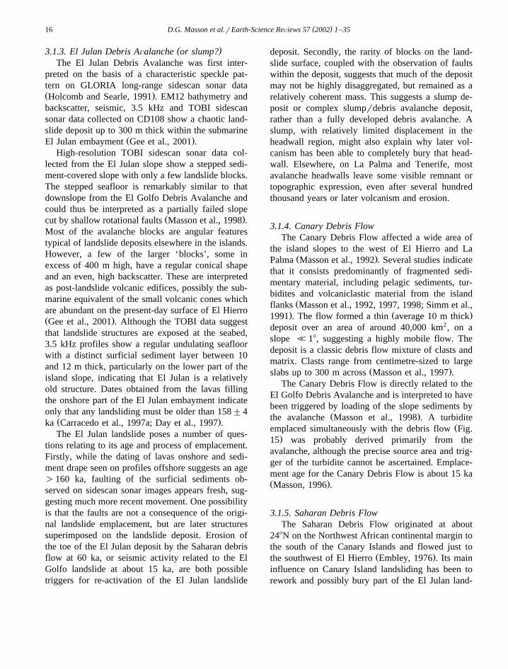
( )3.1.3. El Julan Debris AÕalanche or slump?The El Julan Debris Avalanche was first inter-
preted on the basis of a characteristic speckle pat-tern on GLORIA long-range sidescan sonar dataŽ .Holcomb and Searle, 1991 . EM12 bathymetry andbackscatter, seismic, 3.5 kHz and TOBI sidescansonar data collected on CD108 show a chaotic land-slide deposit up to 300 m thick within the submarine
Ž .El Julan embayment Gee et al., 2001 .High-resolution TOBI sidescan sonar data col-
lected from the El Julan slope show a stepped sedi-ment-covered slope with only a few landslide blocks.The stepped seafloor is remarkably similar to thatdownslope from the El Golfo Debris Avalanche andcould thus be interpreted as a partially failed slope
Ž .cut by shallow rotational faults Masson et al., 1998 .Most of the avalanche blocks are angular featurestypical of landslide deposits elsewhere in the islands.However, a few of the larger ‘blocks’, some inexcess of 400 m high, have a regular conical shapeand an even, high backscatter. These are interpretedas post-landslide volcanic edifices, possibly the sub-marine equivalent of the small volcanic cones whichare abundant on the present-day surface of El HierroŽ .Gee et al., 2001 . Although the TOBI data suggestthat landslide structures are exposed at the seabed,3.5 kHz profiles show a regular undulating seafloorwith a distinct surficial sediment layer between 10and 12 m thick, particularly on the lower part of theisland slope, indicating that El Julan is a relativelyold structure. Dates obtained from the lavas fillingthe onshore part of the El Julan embayment indicateonly that any landsliding must be older than 158"4
Ž .ka Carracedo et al., 1997a; Day et al., 1997 .The El Julan landslide poses a number of ques-
tions relating to its age and process of emplacement.Firstly, while the dating of lavas onshore and sedi-ment drape seen on profiles offshore suggests an age)160 ka, faulting of the surficial sediments ob-served on sidescan sonar images appears fresh, sug-gesting much more recent movement. One possibilityis that the faults are not a consequence of the origi-nal landslide emplacement, but are later structuressuperimposed on the landslide deposit. Erosion ofthe toe of the El Julan deposit by the Saharan debrisflow at 60 ka, or seismic activity related to the ElGolfo landslide at about 15 ka, are both possibletriggers for re-activation of the El Julan landslide
deposit. Secondly, the rarity of blocks on the land-slide surface, coupled with the observation of faultswithin the deposit, suggests that much of the depositmay not be highly disaggregated, but remained as arelatively coherent mass. This suggests a slump de-posit or complex slumprdebris avalanche deposit,rather than a fully developed debris avalanche. Aslump, with relatively limited displacement in theheadwall region, might also explain why later vol-canism has been able to completely bury that head-wall. Elsewhere, on La Palma and Tenerife, mostavalanche headwalls leave some visible remnant ortopographic expression, even after several hundredthousand years or later volcanism and erosion.
3.1.4. Canary Debris FlowThe Canary Debris Flow affected a wide area of
the island slopes to the west of El Hierro and LaŽ .Palma Masson et al., 1992 . Several studies indicate
that it consists predominantly of fragmented sedi-mentary material, including pelagic sediments, tur-bidites and volcaniclastic material from the island
Žflanks Masson et al., 1992, 1997, 1998; Simm et al.,. Ž .1991 . The flow formed a thin average 10 m thick
deposit over an area of around 40,000 km2, on aslope <18, suggesting a highly mobile flow. Thedeposit is a classic debris flow mixture of clasts andmatrix. Clasts range from centimetre-sized to large
Ž .slabs up to 300 m across Masson et al., 1997 .The Canary Debris Flow is directly related to the
El Golfo Debris Avalanche and is interpreted to havebeen triggered by loading of the slope sediments by
Ž .the avalanche Masson et al., 1998 . A turbiditeŽemplaced simultaneously with the debris flow Fig.
.15 was probably derived primarily from theavalanche, although the precise source area and trig-ger of the turbidite cannot be ascertained. Emplace-ment age for the Canary Debris Flow is about 15 kaŽ .Masson, 1996 .
3.1.5. Saharan Debris FlowThe Saharan Debris Flow originated at about
248N on the Northwest African continental margin tothe south of the Canary Islands and flowed just to
Ž .the southwest of El Hierro Embley, 1976 . Its maininfluence on Canary Island landsliding has been torework and possibly bury part of the El Julan land-

( )D.G. Masson et al.rEarth-Science ReÕiews 57 2002 1–35 17
Fig. 15. Summary of the ages of volcaniclastic turbidites em-Ž .placed on the Madeira Abyssal Plain within the last 1.3 Ma left
compared with the ages of landslides derived by dating onshoreŽ .volcanic sequences right . Onshore dates shown by solid lines are
well constrained age ranges; dotted lines show greater uncertainty.Some dates for landslides older than 1.3 Ma have been determinedonshore Tenerife, but are too poorly constrained to be plotted. Therecord of volcaniclastic turbidites on the abyssal plain extendsback to 17 Ma, although such turbidites became much more
Ž .common after 7 Ma see text for further discussion .
Ž .slide deposit Gee et al., 1999 . TOBI sidescan sonardata collected on CD108 clearly shows erosion of ElJulan landslide material in some areas and onlap ofSaharan debris flow material onto the El Julan slopein other areas. Calculations based on the area andpossible thickness of the volcaniclastic component of
Ž .the Saharan Debris Flow Gee et al., 1999 indicatethat 40 km3 or more of volcaniclastic Canary Islandslope sediments must have been removed by and
incorporated into the Saharan Debris Flow. Much ofthis is likely to have come from reworking of ElJulan landslide deposit. It is possible that erosion ofthe toe of the El Julan landslide may have causedfailure within the landslide deposit upslope. Thismight account for the apparent freshness of theshallow rotational faults which cut the landslide de-posit on the lower slope. The Saharan Debris Flowhas an age of about 60 ka, based on nannofossildating of cores which penetrated the feather edge of
Ž .the deposit Gee et al., 1999 .
3.2. La Palma
A large complex of debris avalanche deposits,covering an area of about 2000 km2, forms a distinctlobate topographic bulge on the seafloor on the
Ž .western flank of La Palma Figs. 3, 5 and 16Ž .Urgeles et al., 1999 . Four distinct debris avalanchelobes can be distinguished, representing at least twoand probably as many as four landslide events. Theyoungest Cumbre Nueva landslide can be clearlydistinguished from older deposits, grouped under thename Playa de la Veta landslide complex. A singlelandslide deposit, Santa Cruz, is also recognised onthe eastern flank of La Palma.
3.2.1. Cumbre NueÕa Debris AÕalancheThe Cumbre Nueva Debris Avalanche, covering
an area of around 780 km2 and with a volume ofabout 95 km3, is the youngest debris avalanche on
Ž .the west flank of La Palma Urgeles et al., 1999 .The avalanche deposit forms a clear topographicbulge on the island flank between 2500 and 4000 m
Ž .water depth Figs. 3 and 12 . The failure scar associ-ated with this landslide extends onshore into thevalleys bounded by the Caldera de Taburiente andthe Cumbre Nueva Ridge, although the scar has been
Žmuch degraded by later fluvial erosion Carracedo et.al., 1999 . The blocky nature of the debris avalanche
deposit is confirmed by TOBI sidescan sonar dataŽ .Urgeles et al., 1999 . Evidence for the age of theCumbre Nueva Avalanche is limited. The youngestrocks in the headwall, approximately 530 ka in age,give the maximum age; the oldest overlying lavas,125 ka in age, give the minimum age. The record ofvolcaniclastic turbidites in the Madeira Abyssal PlainŽ .MAP , which would be expected to contain evi-

( )D.G. Masson et al.rEarth-Science ReÕiews 57 2002 1–3518
dence of any event on the western La Palma flank,suggests an age of between 420 and 500 ka. Thisinference can be drawn because the MAP recordcontains no younger volcaniclastic turbidites unattri-
Ž . Ž .buted to other sources Fig. 15 Masson, 1996 .
3.2.2. Playa de la Veta Debris AÕalanche ComplexOn the west flank of La Palma, debris avalanche
deposits older than those of the Cumbre Nuevalandslide are grouped under the name Playa de la
ŽVeta Debris Avalanche Complex Urgeles et al.,.1999 . Three distinct debris lobes can be mapped
between about 1000 and 3000–4000 m water depth,each forming a topographic bulge with rough surface
Ž .topography Figs. 5 and 12 . Seismic profiles show aconsistent chaotic signature within the interpreted
Ž .debris lobes Urgeles et al., 1999 . The boundariesbetween the lobes are marked by incised channelswhich post-date avalanche emplacement, with chan-nel locations apparently controlled by the topo-
Ž .graphic lows between debris lobes Fig. 16 . Al-though the age relationship between lobes is unclear,it seems likely that each represents a distinct
Ž .avalanche event Urgeles et al., 1999 . In total, thePlaya de la Veta Debris Avalanche complex maycontain as much as 650 km3 of material. The age ofemplacement is poorly constrained, but is probably
Ž .in the range 800 ka to 1 Ma Urgeles et al., 1999 .
3.2.3. Santa Cruz Debris AÕalancheA limited reconnaissance survey of the east flank
of La Palma was carried out using the EM12 swathsystem. An area of blocky terrain, identified fromEM12 backscatter data, is interpreted as a single lobeof debris avalanche deposits, here referred to as theSanta Cruz Debris Avalanche. The area of debrisavalanche deposit is in the order of 1000 km2. Thedebris avalanche headwall appears to lie in the vicin-ity of the coastal embayment around Santa Cruz onthe east side of the island. However, there is littlemorphological evidence for a collapse scar either onland or on the upper island slope. This would suggestthat the failure scar has been filled by later volcan-ism associated with the formation of the CumbreNueva and Taburiente volcanoes, suggesting an age
Ž .in the order of 1 Ma Carracedo et al., 1997b .
3.3. Tenerife
Tenerife is the highest and, in terms of surfacearea, the second largest of the Canary Islands. Debrisavalanche deposits were first recognised offshore
Ž .Tenerife by Watts and Masson 1995 , who notedthat these deposits covered much of the submarine
Ž .northern flank of the island Figs. 6, 12 and 17 .They also recognised that these deposits were theproduct of several episodes of avalanching, although
Fig. 16. 3D image of the western flank of La Palma showing the complex topographic bulge made up of multiple debris avalanche deposits.Dashed lines mark the various debris lobes, separated by channels which are post avalanche features which follow the topographic lowsbetween lobes. View is from the southwest.

( )D.G. Masson et al.rEarth-Science ReÕiews 57 2002 1–35 19
Fig. 17. 3D image of the north flank of Tenerife viewed from the northwest. Note the strong morphological contrast between the stable slopein the east and the area affected by multiple landslides in the west. The southern wall of the Canadas Caldera, to the south of Teide, is
Ž .interpreted as the headwall of the Icod and probably Roques de Garcia landslides see text for further discussion .
they were unable to separate the various events withŽ .any degree of confidence. Watts and Masson 1998
further developed the concept of multiple avalancheepisodes, recognising at least four avalanche eventsŽ .Figs. 6, 12 and 17 . These have produced a largearea of debris avalanche deposits with a combined
3 Žvolume estimated at 1000 km Teide Group, 1997;.Watts and Masson, 1995, 1998 . A fifth debris
avalanche deposit is also recognised on the south-eastern flank of Tenerife, downslope from the Guimar
Ž . Ž .valley Fig. 12 Krastel et al., 2001 . In addition, atŽleast two older landslide breccias at 2–3 Ma and
.about 6 Ma have been recognised from onshoreŽrock exposures of limited extent Cantagrel et al.,
.1999 . The deposits from these landslides have notbeen mapped offshore.
3.3.1. Icod debris aÕalancher flowŽThe Icod debris avalanche or debris flow, see
.Discussion is the youngest on the north flank ofŽTenerife, with an estimated age of 170 ka Cantagrel
.et al., 1999; Watts and Masson, 1995 . The areaaffected by the avalanche is up to 20 km wide and
Ž .105 km long Fig. 12 . Constraints on the thickness
Ž .and thus volume of the avalanche deposit are poor.ŽSteep margins to the deposit, up to 45 m high Watts
.and Masson, 2001 , give a minimum thickness, but alack of penetration on high-resolution seismic pro-files prevents assessment of its thickness over mostof its area. TOBI 30 kHz sidescan sonar data show ahigh backscatter, blocky seafloor in the area of theavalanche deposit. Blocks are much smaller and farmore numerous than seen on comparable imagesfrom the El Golfo Debris Avalanche deposit, exceptat the margins of the Icod deposit which are markedby a ‘halo’ of very large blocks up to 1.5 km acrossŽ .Fig. 11 . Flow structures, in the form of flow-paral-lel shear structures, aligned blocks and flow-per-pendicular ridges, are clearly visible on the sidescan
Ž .images Watts and Masson, 2001 . On 3.5 kHzprofiles, no discernible sediment cover can be seen
Ž .draping the debris deposit Fig. 18 . At water depthsshallower than about 3 km, the deposit can be tracedupslope into a linear depression about 10 km wideand up to 400 m deep, with a relatively flat bottom
Ž .and steep-sided margins Watts and Masson, 2001 .This Achute-likeB structure extends into the subaerialIcod valley and appears to be erosional in origin. The

( )D.G. Masson et al.rEarth-Science ReÕiews 57 2002 1–3520
Fig. 18. 3.5-kHz profile crossing part of the Icod and Roques de Garcia debris avalanche deposits. The Roques de Garcia avalanche depositis overlain by a distinct sediment layer which is absent over the Icod deposit. For location see Fig. 3.
head of the Icod Valley appears to extend into theCanadas Caldera, but the relationship between thevalley and the caldera is largely obscured by thevolcanic products of the younger strato-volcano ofTeide Pico Viejo. The origin of the caldera is thefocus of much current debate, with arguments for itscreation by vertical collapse related to magmaticactivity, a combination of vertical and lateral col-lapse, or solely by lateral collapse due to large-scale
Ž . Žlandsliding see Discussion Ancochea et al., 1998,1999; Cantagrel et al., 1999; Marti et al., 1997;Navarro and Coello, 1989; Ridley, 1971; Watts and
.Masson, 1995, 1998, 2001 .
3.3.2. OrotaÕa Debris AÕalancheNew offshore data collected during Charles Dar-
win cruise 108, integrated with the most recent workŽ .onshore Cantagrel et al., 1999 , suggests that the
Orotava Debris Avalanche can be mapped as a dis-tinct debris lobe extending due north from the Oro-
Ž .tava Valley Figs. 6 and 12 . The Orotava DebrisAvalanche has a typical blocky character on sidescan
Žsonar and EM12 backscatter data Watts and Mas-. Ž .son, 1998, 2001 Figs. 8 and 10 . The apparent
density of blocks and the backscatter level are bothlower than for the adjacent Icod Debris AvalancheŽ .Figs. 8 and 10 , probably reflecting the greatersediment cover on, and hence age of, the Orotavaavalanche. High resolution seismic profiles crossingthe distal part of the Orotava Debris deposit showthat this sediment cover is thicker than previously
Žrecognised, reaching 20 m or so in thickness Fig..19 . At a large scale, the surface of the avalanche is
characterised by longitudinal ridges and valleys witha peak to trough amplitude of 300 to 400 m and a
Ž .wavelength of 5 to 8 km Watts and Masson, 1995 .These are interpreted as ridges of debris separated bychannels or chutes which were the main debris trans-port pathways. Sidescan sonar data gives the impres-sion that the ridges are characterised by larger and

( )D.G. Masson et al.rEarth-Science ReÕiews 57 2002 1–35 21
Ž .Fig. 19. High resolution multichannel seismic profile and interpretation across the distal part of the Orotava debris avalanche deposit. Thisprofile indicates a layer of post-avalanche sediment up to 20 m thick.
more numerous blocks compared to the valleys.However, this may be due to greater post emplace-ment sedimentation in the valleys.
The Orotava Debris Avalanche can be tracedŽupslope into the Orotava Valley on Tenerife Figs. 6
.and 12 . Morphologically, the subaerial Orotava Val-ley, with its flat floor flanked by steep scarpsŽ .Palacios, 1994; Ridley, 1971 , is the most distinctlandslide-related valley on Tenerife. The age of for-mation of the Orotava Valley is estimated at between540 and 690 ka, based on KrAr dating of basalticlavas in the upper part of the landslide scarpŽ .Cantagrel et al., 1999 . An age in the range 500–700ka is compatible with the 20 m or so of sediment
Žcover seen draping the debris deposit offshore Fig..19 . Orotava is believed to have been the product of
the lateral collapse of the Canadas volcano whichpreceded the Teide Pico Viejo complex. It is one ofthe largest landslides to have occurred in the westernCanary Islands. Taken together, the volume of debrisavalanche deposits on the central part of the north
Žflank of Tenerife from the Icod, Orotava, Roques de.Garcia and possible other older avalanches has been
3 Žestimated at more than 1000 km Teide Group,.1997; Watts and Masson, 1995 . Probably -50% of
this volume can be ascribed to the Orotava avalanche,although the existing data does not allow us toestimate volumes for the individual debris avalanchedeposits with any confidence. In particular, uncer-tainty in the estimate of the thickness of the Orotavadeposit leaves a considerable error margin in thevolume estimate.
3.3.3. Roques de Garcia and Teno Debris AÕalanchesTo the west of the Icod Debris Avalanche, Watts
Ž .and Masson 1998 described a poorly defined, ap-parently older area of landslide deposits, which theyreferred to as the Teno Debris Avalanche. Althoughdata collected during Charles Darwin cruise 108 has
Žallowed us to better define this avalanche area Figs..6, 12 and 17 , the new data also confirms the
difficulty in mapping landslide boundaries withinthis topographically complex area which was proba-bly affected by at least two distinct landslides priorto the Icod landslide. The more recent of these canbe traced onshore to the west of the Icod Valley,strongly suggesting a correlation with the Roques de
ŽGarcia debris avalanche inferred onshore Cantagrel.et al., 1999 . Thus we now refer to this avalanche as
the Roques de Garcia debris avalanche. ‘Teno debris

( )D.G. Masson et al.rEarth-Science ReÕiews 57 2002 1–3522
avalanche’ is now used to describe possible olderavalanche deposits, recognised on the upper part ofthe submarine slope west of the area affected by theRoques de Garcia landslide.
The character of the Roques de Garcia avalanchedeposit, when seen on sidescan sonar, EM12 or 3.5kHz profile data, is similar to that of the Orotava
Ž .avalanche deposit see previous section . In the mostnorthern part of the debris deposit, away from theareas affected by the Orotava and Icod events, sides-can sonar and EM12 backscatter data show numer-ous, widely scattered small blocks on a backgroundof smooth sedimented seafloor. Seismic profiles showthat this smooth seafloor is the result of between 10and 25 m of sediment overlying the avalanche de-posit.
The age of the inferred Roques de Garciaavalanche is not well constrained onshore, althoughit is probably )600 ka and possibly )1 Ma in ageŽ .Cantagrel et al., 1999 . An age slightly greater thanthat of the Orotava avalanche is compatible with theslightly thicker post-emplacement sediment coverseen offshore. The volume of the Roques de Garciaavalanche deposit cannot be determined, but giventhe large area it covers, it is likely to be of the sameorder as that of the Orotava deposit. The area of theTeno massif, in the extreme northwest of Tenerife,appears to have a landslide history extending back to
Ž .between 5.0 and 6.0 Ma Cantagrel et al., 1999 .However, the limited extent of the evidence forlandsliding, both in the form of landslide brecciasonshore and slope morphology offshore, allows littleof the detail of this history to be deduced.
3.3.4. Anaga Debris AÕalancheThe Anaga landslide scar is recognised primarily
on the basis of its topographic and morphologicalŽ . Žexpression Watts and Masson, 1998 Figs. 6 and
.17 . It forms a distinct embayment which extendsfrom the shelf edge to about 3000 m water depth.The seafloor within this embayment is characterisedby a series of large-scale gullies and ridges, with awavelength of up to 5 km and an amplitude of a few
Ž .tens of metres Fig. 6 . A possible associated debrisdeposit is indicate by a topographic bulge in the
Ž .region of the 3200 m contour Fig. 3 .Anaga appears to be one of the older landslides to
have affected Tenerife. Its western boundary is on-
lapped by the Orotava Debris Avalanche, indicatingit must at least be older than about 600 ka. Watts and
Ž .Masson 1998 report up to 100 m of post-landslidedrape covering this landslide, indicating that Anagamay be 41 Ma in age. The age of the landslide isalso reflected by the presence of a 5-km-wide wave-cut shelf around the Anaga massif, which has beenformed since landsliding.
3.3.5. Guimar Debris AÕalancheOn the southeastern flank of Tenerife, a broad
area of hummocky topography, corresponding to anarea of distinctive speckled pattern on EM12 back-scatter images, is interpreted as a debris avalancheextending east from the subaerial Guimar ValleyŽ . ŽKrastel et al., 2001; Teide Group, 1997 Figs. 6
.and 12 . This landslide is unusual because it is theonly example described from the Canary Islands tohave occurred on a buttressed flank, the buttressbeing the island of Gran Canaria. This island appearsto have deflected the debris avalanche slightly to-ward the northeast.
The subaerial valley of Guimar is around 10 kmwide with a relatively flat base and well-definedflanking scarps between 300 and 600 m high. In itsupper part, the Guimar Valley forms two divergingsub-valleys separated by a low ridge. Both sub-val-leys extend onto the dorsal ridge, a narrow ridgeseparating the Orotava and Guimar Valleys. Basedon the age of infilling lavas, the valley is estimated
Žat around 0.78 to 0.83 Ma in age Ancochea et al.,.1990; Cantagrel et al., 1999 .
4. Discussion
4.1. Flow and deposit statistics
4.1.1. Rates and Õolumes of landslide erosionAn understanding of the effect of large-scale land-
sliding on volcanic island evolution requires a com-parison between the rate of island construction byvolcanic processes and the rate of material removalby landsliding. The rate of erosion by landslidescritically depends on our ability to produce accurateestimates of landslide ages and volumes. The latter

( )D.G. Masson et al.rEarth-Science ReÕiews 57 2002 1–35 23
can be estimated either from the volume of thelandslide scar or the volume of the landslide depositŽMasson, 1996; Urgeles et al., 1997, 1999; Watts and
.Masson, 1995 . Ideally, volumes should be calcu-lated for both scar and deposit, thus reducing theamount of error.
Some assumptions usually have to be made in theestimate of landslide deposit volume. For example,estimates of the deposit volume are often based onits topographic anomaly, since the base of suchdeposits is rarely imaged by seismic profiling tech-niques. Little is known about the porosity of land-slide deposits, so any increase in volume caused byfragmentation during landslide emplacement is ig-nored. Loss of material from the landslide mass mayoccur due to its entrainment into turbidity currents ordebris flows, while material may be added by ero-sion of the seafloor over which a landslide travels.However, these changes are usually impossible toestimate and have to be ignored, with the assumptionthat they are small compared to overall landslidevolume.
Estimates of landslide volume independentlybased on the volume of its scar and deposit usuallygive comparable results when applied to relativelyrecent landslides, where the landslide scar has beenlittle modified by erosion or later volcanic activityand the deposit can be identified as a distinct topo-graphic bulge with clearly definable boundaries. Forthe El Golfo avalanche on El Hierro, the volume ofthe avalanche scar can be estimated at about 180
3 Ž .km Fig. 20 . This compares favourably with avolume of about 150 km3 calculated for the depositŽ .Urgeles et al., 1997 , with the difference probablyaccounted for by avalanche material incorporatedinto the Canary debris flow or transported downslopeby the turbidity current associated with avalanche
Ž .emplacement Masson, 1996 . The correspondencebetween the two volume estimates gives clear confi-dence in the calculation methods. The reliable vol-ume estimate, in turn, gives confidence that El Golforesulted from a simple, single flank failure. Sugges-tions that the most recent El Golfo landslide oc-curred within the El Golfo embayment, but affected
Ž .only the offshore segment Carracedo et al., 1997aŽare not supported by the volume assessment Fig.
. Ž20 , nor the offshore mapping evidence Masson et.al., 1996 . Similarly, suggestions that El Golfo might
Žhave been location of a 2 kmq high volcano Car-.racedo et al., 1997a are not supported by the volume
of debris mapped offshore.When the landslide scar has been heavily modi-
fied by later volcanism andror erosion, as in thecase of the Caldera de Taburiente on La PalmaŽ .Carracedo et al., 1999 , landslide volume can onlybe estimated from the volume of the deposit. For asingle deposit on any island flank, a reliable esti-mate, based on the volume of the topographicanomaly associated with that deposit, appears to be
Ž .possible Urgeles et al., 1999 . Where multiple over-lapping landslide deposits occur, such as north ofTenerife or west of La Palma, it is usually possible
Žonly to estimate overall debris volumes Urgeles et.al., 1999 . In the case of multiple deposits covering
large areas, the assumptions relating to the geometryof the pre-landslide island flank become correspond-ingly large, and volume estimates correspondinglyless reliable. For example, where landslides cover abroad sector of island flank, such as the Playa de laVeta complex on the west side of La Palma, assum-ing a flat seafloor may lead to an overestimate oflandslide volumes because of the natural curvature ofthe island flank.
In some cases, such as north of Tenerife and westof La Palma, the volume of landslide deposits off-shore is substantially greater than the volume of the
Žlandslide scars onshore Cantagrel et al., 1999; Urge-.les et al., 1999; Watts and Masson, 1995 . In the
case of the north flank of Tenerife, this apparentdiscrepancy can be explained, on the basis of on-shore geological evidence, by repeated cycles ofvolcanic construction and failure of the same general
Ž .area of flank Cantagrel et al., 1999 . A similarsituation is seen on the island of Reunion and canalso be explained by repeated volcanic buildup andfailure cycles.
When compared to the volume of the individualvolcanic islands, debris avalanche deposits around ElHierro and La Palma account for about 10% of thetotal volcanic edifice. For La Palma, the volume of
Ž .the edifice above the present day seafloor is about3 Ž .6500 km Urgeles et al., 1999 and the volume of
known debris avalanches is about 600–800 km3
Ž .Table 1 . Corresponding figures for El Hierro are3 3 Ž .5500 km and 400–500 km Gee, 1999 . Individual
landslides may remove as much as 25% of the

( )D.G. Masson et al.rEarth-Science ReÕiews 57 2002 1–3524
Fig. 20. Series of reconstructed cross-sections through the El Golfo landslide scar showing the uncertainty in calculating landslide volumeson the basis of the scar. The upper cross-section shows present day profiles, heavily smoothed to remove the effects of local features, suchas volcanic cones or gullies. The lower three profiles show calculations of the possible landslide volume, based on variable assumptionsdetailed on the figure.

( )D.G. Masson et al.rEarth-Science ReÕiews 57 2002 1–35 25
subaerial part of an individual island. This is impor-tant in understanding the hazard potential of suchlandslides. For example, the El Golfo landslide re-moved some 50 km3 of material from an island ofperhaps 200 km3 in volume. Almost 50% of theseafloor within 60 km of the shoreline of El Hierro is
Ž .covered with landslide debris Gee, 1999 .
4.1.2. Relationship between Õolume, runout distance,and height
The relationship between the volume of a land-Ž . Ž .slide V , its runout distance l and the height drop
Ž .between the headwall and the landslide toe h ,usually expressed as hrl plotted against V, is com-monly used as a measure of the relative efficiency of
Ža landslide Hampton et al., 1996; Scheidegger,.1973 . Even allowing for differences in volumes,
landslides on the flanks of the Canary Islands clearlyfall into two categories, with sedimentary debris
Ž .flows Canary and Saharan flows having a hrl ratiomore than an order of magnitude lower than any of
Ž .the debris avalanches on the island flanks Table 1 .Canary Island debris avalanches plot in the same
Žfield as Hawaiian debris avalanches Hampton et al.,.1996 . The Icod ‘debris avalanche’, which we argue
below exhibits many of the characteristics of a debrisflow, has an hrl ratio toward the lower end of thedistribution for ‘debris avalanches’, but is barelydistinguished from other Canary Island ‘debrisavalanches’ by this measure.
Ž .Dade and Huppert 1998 showed that the runoutof rockfalls was related to their potential energy andto the area over which they spread. A relationship
Ž . Ž .2r3between area A and volume V was deter-mined. Canary Island debris avalanches fall on thetrends predicted by this analysis, suggesting typicalrockfall behaviour. Canary Island sedimentary debrisflows, in contrast, spread over much greater areas
Ž .relative to their volume see Table 1 . The spread ofvalues of the ArV 2r3 ratio seen for the variousCanary Island debris avalanches is not consideredsignificant, given the uncertainties in estimating bothA and V. The former, in particular, should strictly becalculated as the area covered by the landslide de-posit, rather than the total area affected by landslid-ing, i.e., scar plus deposit, as it is only possible toestimate here.
4.2. Character and distribution of landslides
4.2.1. Canarian landslidesMost Canarian landslides take the form of debris
Ž .avalanches Table 1 . The typical Canary Islanddebris avalanche has an overall lobate shape andextends from a subaerial headwall scarp to a blockydebris deposit in 3000–4000 m water depth. Mostdebris avalanche scars have a relatively narrow head-wall region and ‘chute’ above 3000 m water depth,where erosion and downslope transport dominate,and a broader deposition lobe below 3000 m water
Ž .depth Fig. 12 . Sidescan sonar images show thatalthough debris avalanche deposits have a typicalblocky structure, block size and the degree of frag-mentation of the avalanche material are variableŽ .Figs. 10 and 11 . At one extreme, El Golfo haslarge blocks scattered randomly across the avalanchesurface. At the other, Icod has much more numerousbut smaller blocks over most of its surface, with afew large blocks confined to the margins of thedeposit. The primary controls on the block structureand distribution are likely to be the nature of the
Žlandslide material e.g., volcanic or intrusive rocks,.pyroclastic deposits or volcaniclastic sediments and
Žthe flow processes e.g., flow or avalanche, speed of.emplacement . This is further discussed below.
Only two landslides in the western Canaries mightŽtentatively be identified as slumps as defined by
.Moore et al., 1989; Table 1 . These are the LasPlayas I and possibly El Julan landslides on the
Ž .flanks of the island of El Hierro Fig. 12 . Evidencefrom Hawaii indicates that slumps affect a consider-able thickness of or even the whole volcanic edifice,and that movement on the decollement at the base ofthe slump occurs within sediments between theoceanic crust and the base of the volcanic edificeŽ .Moore et al., 1994 .
One possible explanation for the more commonoccurrence of deep-seated slumps around HawaiianIslands relative to the Canary Islands is that Hawaii,unlike the Canary Islands, is associated with a largeamplitude topographic swell. The Hawaiian plumealso has greater melt production rates than the Ca-
Ž .nary plume e.g., White, 1993 . The combined effectof these processes is that Hawaii may have beenmaintained at a greater elevation for longer timesthan the Canary Islands, thus increasing the gravita-

( )D.G. Masson et al.rEarth-Science ReÕiews 57 2002 1–3526
tional potential which drives the slumping process. Itmight also be speculated that slumps would be morecommon on young volcanic islands, such as El Hi-erro, where rapid growth of the volcanic edificeimposes a rapidly changing load on the underlyingpoorly consolidated sediments. For islands withlonger histories, such as Tenerife, consolidation ofthe underlying sediments under loading and a ten-dency toward a balance between volcanic growthand erosive processes may reduce the likelihood ofslumping. In addition to the landslides identifiedoffshore, faulting associated with the 1949 volcaniceruption on La Palma could be a superficial indicatorof deeper slump-type deformation of the young,
Žsouthern volcanic edifice on that island Carracedo et.al., 1999 . Fault downthrow to the west of a Afew
metresB was observed on a 4-km-long fault systemŽ .Carracedo, 1996; McGuire, 1996 . The magnitudeof this movement is similar to that observed duringthe 1975 event on the Hilnia Slump in Hawaii,although fault movement on Hawaii occurred over a
Ž .much greater lateral extent Moore et al., 1989 .However, no evidence of slumping has been ob-served on the offshore flank of La Palma, and all ofthe landslides affecting the older northern part of the
Ž .island are debris avalanches Fig. 12 .Large-scale sediment failures leading to debris
flows do not appear to be common on the flanks ofthe Canary Islands, with only one documented exam-ple, the Canary debris flow, having its source on theisland slopes. Relationships between debris flowsand other landslide types are further discussed be-low.
4.2.2. Controls on landslide locations in the westernCanary Islands
A model linking volcanic rift zones and landslid-ing in the Canary Islands was proposed by CarracedoŽ . Ž .1994,1996 and Carracedo et al. 1998 . This modelis based on the observation that volcanism at manyoceanic islands and seamounts is concentrated on aseries of volcanic rift zones radiating from the centre
Žof the volcanic edifice Fiske and Jackson, 1972;.Vogt and Smoot, 1984 . The resulting stellate edifice
geometry may be further enhanced by landslidingbetween the rift arms, with landslides commonly
Žpropagating perpendicular to the rift direction Moore.et al., 1989 . Three-armed rifts, spaced at 1208, seem
Ž .to be the naturally preferred least horizontal stress?situation, as in the case of El Hierro and TenerifeŽ .Carracedo, 1994,1996; Carracedo et al., 1998 .
ŽHowever, single rifts or systems where one arm of a.multiple rift system becomes dominant , leading to
elongate volcanic edifices, are also seen, as in south-Ž .ern La Palma Carracedo et al., 1999 . In the case of
La Palma, the single rift may result from buttressingof the young southern rift by the older northern partof the island.
Although the proposed link between rifts andlandslide location can explain the overall distributionof landslides and stable island flanks, it does notentirely explain the uneven distribution of landslidesaround some islands. On both La Palma and Tener-ife, multiple landslides have occurred on one particu-lar flank, while other areas have remained more
Ž . Žstable over long periods Fig. 12 Krastel et al.,.2001; Urgeles et al., 1999; Watts and Masson, 1998 .
This suggests that once established, an unstable flankbecomes a weakness which can be carried forward inthe development of the island. Several factors maycontribute to this phenomenon. Firstly, failures maybe most easily initiated on island flanks which havethe greatest gravitational potential for movement,i.e., those which are steepest andror extend to greaterwater depths and are least buttressed by the sur-rounding topography. This might result in extensionon island rift zones being asymmetrically directedtoward the least buttressed flank, increasing the pos-sibility of this flank becoming detached and failing.This would appear to be a possible scenario in thecases of La Palma and Tenerife. Secondly, by locallydecreasing the overburden on any underlying mag-matic system, the removal of part of an island bylandsliding may focus later magmatism to the regionof the landslide scar. Preferential accumulation ofnew volcanic products within the scar may thenincrease the probability of future instability in thatarea. This may be a factor in the case of Tenerife,where multiple failures appear to have originated
Žfrom approximately the same source area Cantagrel.et al., 1999 . Thirdly, landslide breccias within old
landslide scars may form weak layers, prone tofailure when loaded by new volcanic productsŽAncochea et al., 1999; Cantagrel et al., 1999;
.Labazuy, 1996; Watts and Masson, 2001 . Finally, inthe case of Tenerife in particular, the concentration

( )D.G. Masson et al.rEarth-Science ReÕiews 57 2002 1–35 27
of rainfall on the north side of the island mayincrease pore water availability at shallow depthswithin the volcanic edifice, with the possibility thatthis may increase the risk of landsliding.
4.2.3. Comparisons with other areasLarge-scale landsliding is recognised on many
Žoceanic island volcanoes Holcomb and Searle,.1991 . Blocky debris avalanche deposits, similar to
those on the Canary Island flanks, are widespread onŽthe flanks of the Hawaiian Ridge Moore et al.,
. Ž1989, 1994 and off Reunion Labazuy, 1996; Ollier.et al., 1998 . Other volcanic islands, such as Strom-
boli and Etna in the Mediterranean Sea, exhibit clearmorphological evidence of landslide scars onshoreŽ .Rust and Neri, 1996; Tibaldi, 1996 .
A close relationship between volcanic rift zonesand landslides, similar to that proposed for the Ca-naries, is seen in the Hawaiian Islands, where it is
Žgenerally observed that landslides both slumps and.debris avalanches move perpendicular to rift zones
Ž .Moore et al., 1989 . Proposed controlling mecha-nisms imposed by the rift zone include severing ofthe updip attachment of a landslide mass due to dykeinjection and the creation of excess pore pressures in
Žthe landslide mass due to magma injection Elsworth.and Voight, 1995 . However, a circular riftrlands-
lide relationship can also be envisaged, becauseextension on rift zones generated by gravitationalmovement may also facilitate magma injectionŽ .Moore et al., 1989 .
The eastern flank of Piton de la Fournaise volcanoon Reunion Island appears to have suffered repeatedfailures similar to those on the north flank of Tener-
Ž .ife Labazuy, 1996 . Here, an offshore landslidedeposit some 550 km3 in volume, much of whichconsists of subaerially erupted basalts, is associatedwith an onshore landslide scar almost an order ofmagnitude smaller on the island, a situation similarto that on Tenerife. Three landslides appear to haveoccurred in the last 150 ka, indicating a landslidesystem more active than that on Tenerife.
4.3. Failure processes on the Canary Island flanks
4.3.1. Triggering mechanismsAlthough the general relationship between rift
zonesrdyke injection and landsliding is largely ac-
cepted, little is known about the mechanisms whichtrigger individual large-scale volcano flank land-slides. At one end of the spectrum, large slump-typelandslides, driven by gravitational instability, maycreep continuously and require no specific triggers to
Ž .initiate movement McGuire, 1996; Rasa et al., 1996 .However, as evidenced by the 1975 movement onthe Hilnia Slump on Hawaii, even large slumpsare capable of essentially instantaneous movementŽ .Moore et al., 1989 . The 1975 slump movement wasaccompanied by both a large earthquake and a smallvolcanic eruption. However, as noted by Moore et al.Ž .1989 , it is not clear whether slump movementcaused these associated phenomena, or dyke injec-tion linked to the volcanic eruption or the earthquakewas the original trigger of slump movement.
At the other end of the spectrum, debris avalanchesare instantaneous failures. Small debris avalanchesare frequently associated with volcanic eruptions,such as the 1980 eruption of Mount St. Helens in theUnited States. In this type of debris avalanche, fail-ure usually results from oversteepening due to rapidedifice growth over a relatively short period; seis-micity related to the eruption may also play a role in
Ždefining the precise moment of failure see review in.McGuire, 1996 . In the case of oceanic islands,
however, large-scale debris avalanches are infrequentevents which punctuate long periods of apparentlystable volcanic growth. In the western Canary Is-lands, the return period for landslides on each indi-
Žvidual island is a few hundred thousand years Fig..15 . There is no particular evidence that failures are
related to periods of unusual volcanic activity, al-though we recognise the limited resolution of theisland volcanic records in this context. Thus landslid-ing appears to a response to long-term volcanicbuild-up to a point where the load on the volcanicedifices exceeds that which it can support. When thiscritical point is reached, a relatively minor triggermay be all that is required to initiate a landslide.Thus events that have occurred commonly through-
Ž .out construction of the stable volcanic edifice, suchas dyke injection or seismicity, may be critical intriggering failure. Increases in pore pressure relatedto magma intrusion, which can destabilise a previ-ously stable edifice without any change in the mor-
Žphology of that edifice, may be crucial Day, 1996;.Elsworth and Voight, 1995 .

( )D.G. Masson et al.rEarth-Science ReÕiews 57 2002 1–3528
Climate change and, more particularly, relatedfluctuations in sealevel may also affect the stressregime within an oceanic volcanic island, as sug-gested by links between sealevel and the intensity of
Žexplosive volcanism in the Mediterranean Sea Mc-.Guire et al., 1997 . Such stress changes could also
affect flank stability. More speculatively, for theCanaries, climate change may be linked to changesin rainfall, in turn affecting groundwater level withinthe volcanic edifices. Heating of groundwater bymagma intrusion may contribute to pore pressureincreases and hydrothermal alteration, leading toweakening of the edifice structure in the manner
Ž .suggested by Day 1996 . Accurately dated CanaryIsland landslides are too few in number to allow astatistical evaluation of any possible link with cli-
Žmate. Dating of volcaniclastic turbidites thought to.be generated by landsliding on the island flanks in
the Madeira Abyssal Plain sequence to the west ofŽ .the Canaries is also inconclusive Fig. 15 . Seven
such turbidites are recognised within the part of thesequence dated using the oxygen isotope age scale,directly correlated with climate. Four of these coin-cide with isotope stage boundaries, indicating peri-ods of climate change, while two occurred duringsealevel highstand and one during sealevel lowstand.
4.3.2. Flow processesLandslides on the Canary Island flanks involve a
range of processes including slumping, debris flowand debris avalanche. It is important to recognisethat these are not distinct and separate processes, but
Žpart of a process continuum e.g., Mulder and Co-.chonat, 1996 . Most of the data discussed here gives
information on the surface morphology of landslidedeposits and is most useful in understanding theemplacement of the more superficial landsliding pro-cesses, such as debris avalanches and debris flows,which are dominated by laminar flow processes. Wehave little data on slump emplacement and haveassumed a ‘Hawaiian’ model for these landslidesŽ .Moore et al., 1989, 1994 .
Ž .Debris or rock avalanches are defined as large-scale catastrophic events where the avalanche mate-rial becomes highly disaggregated and energy isdissipated through the avalanche mass by collisions
Ž .between clasts Mulder and Cochonat, 1996 . Debrisavalanches are the dominant landslide type in the
Ž .western Canary Islands Table 1, Fig. 12 . Mostoriginate from a headwall scarp with a distinct am-phitheatre shape, are restricted to a narrow ‘chute’ asthey cross the upper part of the island flank, andspread abruptly into a broad depositional lobe be-yond the distinct decrease in slope gradient which
Ž .occurs at the base of the volcanic edifice Fig. 12 .High-resolution sidescan sonar images of a typicaldebris avalanche deposit, El Golfo on the island ofEl Hierro, show the characteristic features to be arandom distribution of clasts up to 1 km or more indiameter and a general absence of structures indica-tive of flow, such as longitudinal shears or pressure
Ž .ridges see Description of landslides .The characteristic shape of the debris avalanche
deposit beyond the break of slope at the edifice baseand the lack of flow structures on the surface of thedeposit strongly support the idea that the energy ofthe debris avalanche is dissipated by collisions be-tween clasts. As a result of this energy transmissionmechanism, the avalanche spreads laterally in alldirections as soon as it escapes the confines of thechute on the upper island slope, giving the character-istic broad lobate deposit on the lower slope. Spread-ing of the debris avalanche beyond the confines ofthe chute, thus increasing its surface area and lower-ing its thickness, may also contribute to the loss ofexcess pore pressures within the moving avalanche.
The Icod debris landslide deposit differs from allother blocky landslide deposits on the Canary Islandflanks in being much more elongate than typicalavalanche deposits, because of the occurrence offlow structures within the deposit, and because of the
Žhalo of coarse blocks which mark its perimeter Figs..11 and 12; Watts and Masson, 2001 . Almost all of
Žthe characteristics of the Icod flow see De-.scription of landslides can be reproduced in large-
scale coarse-grained debris flow experiments, givinga strong insight into the flow processes which con-
Žtrolled Icod emplacement Iverson, 1997; Major,.1997; Major and Iverson, 1999 . Such experimental
flows typically produce elongate debris lobes withŽgravel ridges on the surface of the deposit Major,
.1997 . They also produce flows with steep margins,particularly in the distal reaches of the flow, oftenwith a concentration of coarser particles at the mar-
Ž .gin Major and Iverson, 1999 . Measurements ofpore pressure in the interior of flows during their

( )D.G. Masson et al.rEarth-Science ReÕiews 57 2002 1–35 29
emplacement indicate that high pore pressures,Anearly sufficient to cause liquefactionB persistthrough all phases of the flow, from mobilisation todeposition. However, these high pore pressures are
Žabsent from the flow margins Major and Iverson,.1999 . Thus the steep flow margins result from
‘strength’ produced by friction between grains andbetween the flow and the underlying bed. Highfriction at the flow margin causes deposition ofmarginal ridges or levees, effectively damming theflow and halting its forward progress, even thoughhigh pore pressures continue to exist in the flowinterior. Both experimental and natural subaerialflows typically develop a series of surges; successivesurges deposit by pushing aside and forward intomaterial already deposited. Because high pore pres-sures persist in the deposit interior after it comes torest, giving a very weak material, successive surgesare able to deform deposits from earlier surges,producing flow structures such as gravel ridges andlongitudinal shears. Surging flows also produce asingle amalgamated deposit, indistinguishable from asingle en masse debris deposit.
Examination of the shape of debris deposits aroundthe western Canary Islands suggests that El Golfoand Icod form the end members of a series of
Ž .landslide shapes Fig. 12 , probably representing aseries of flow processes ranging from debris
Ž .avalanche more lobate to coarse-grained debris flowŽ .more elongate , respectively. Although most of thelandslides originating on La Palma and El Hierro aresimilar in shape to El Golfo, landslides originatingfrom Tenerife exhibit the whole range of shapes. Wewould suggest that the difference in landslide typeprimarily results from differences in the rock typesinvolved in the landslides. La Palma and El Hierroconsist almost entirely of volcanic extrusives andintrusives of basaltic composition, with only minor
Ž .pyroclastic intervals Carracedo et al., 1997a, 1999 .In contrast, pyroclastic deposits form a significantproportion of the Canadas and younger volcanic
Žsequences preserved on Tenerife Bryan et al., 1998;.Cantagrel et al., 1999 . Our images suggest that
landslides dominated by basaltic rocks give rise to aŽ .coarse-grained breccia Fig. 10 ; this results in a
transport process dominated by grain to grain colli-sion, i.e., a debris avalanche mechanism. Pyroclasticmaterial is much more friable, giving a finer grained
Ž .breccia Fig. 11 and probably a significant propor-tion of fine-grained matrix; this results in a debrisflow mechanism, with the flow supported by ele-vated pore pressure. However, the large blocks at themargins of the Icod flow may be evidence that it wasinitiated as a debris avalanche, converting to a debrisflow as disaggregation took place during transport.The large blocks might have survived either becausethey are composed of less friable basaltic material, orbecause they were carried as rafts by the flow. Suchrafted blocks typically accumulate at flow marginsŽIverson, 1997; Johnson, 1970; Major and Iverson,
.1999 .Experimental studies of coarse-grained debris
flows confirm that the grain-size of the debris isfundamental in determining flow characteristics. In
Žparticular, the addition of even small amounts -.10% of fine-grained material greatly increases the
runout of coarse-grained flows, because Athe fineshelp sustain high pore pressures that reduce frictional
ŽresistanceB, thus increasing runout distance Iverson,.1997 . In the experimental studies, lobate, relatively
short-runout flow deposits, similar in plan view tothe El Golfo landslide deposit, are rapidly depositedimmediately in front of the flume channel mouth bypartially saturated flows. These are considered to beanalogous to Canarian debris avalanches, which can-not sustain high pore pressures because of theircoarse grain-size and corresponding high permeabil-ity. In contrast, saturated experimental flows, partic-ularly those containing some fine-grained material,form elongate bodies with relatively long runout.These are considered to be analogous to the Icoddebris flow, which is considered to have been sup-ported by excess pore pressure which was main-tained over an extended period during flow emplace-ment, allowing the typical debris flow characteristicsto develop. This would indicate that the landslidecontained a significant proportion of fine-grainedmatrix.
4.3.3. Relationships between slumps, debris aÕa-lanches, debris flows and turbidity currents
In the case of the El Golfo landslide, there isconsiderable evidence to suggest that a single land-slide event on the flank of El Hierro gave rise tothree discrete flow phases: debris avalanche, a sedi-
Žmentary debris flow and a turbidity current Masson

( )D.G. Masson et al.rEarth-Science ReÕiews 57 2002 1–3530
.et al., 1996, 1998; Urgeles et al., 1997 . Both thedebris flow deposit and the turbidite contain a com-plex sedimentary assemblage consisting of mixed
Žvolcaniclastics and pelagic slope sediments Masson.et al., 1997; Rothwell et al., 1992 . The sedimentary
debris flow appears to have been triggered by load-ing of the sediments on the lower slopes of the islandŽMasson, 1996; Masson et al., 1998; Roberts and
.Cramp, 1996 . The origin of the turbidity current isŽ .less certain, but Masson 1998 suggested that it may
have been sourced directly from the debris avalanche,rather than from the debris flow. A similar relation-ship between the Icod debris avalanche and a vol-caniclastic turbidite seen both in the Madeira Abyssal
ŽPlain to the west of the Canaries Rothwell et al.,. Ž1992 and the Agadir Basin to the north Wynn et
.al., in press , is suggested by the similarity in ageŽ .between avalanche deposit and turbidite Fig. 15 ,
although in this case we have no direct evidencelinking the two deposits. However, it does support ageneral relationship between island flank landslides
Ž .and turbidites in distal basins Masson, 1996 .In contrast, there is no evidence that debris ava-
lanches generally trigger sedimentary debris flows,since the El Golfo avalancherCanary debris flow isthe only known example of this relationship. Thelarge age difference the El Julan slumpravalanche
Ž .and the Saharan debris flow Fig. 15 indicates thatŽ .despite their partial overlap Fig. 12 , there is no
direct relationship between them. However, the pres-ence of volcaniclastic debris from the El Julan land-slide in the sub-seafloor succession overridden bythe Saharan debris flow was clearly a major factorcontrolling the exceptional runout of the Saharan
Ž .flow Gee et al., 1999 .The turbidite record of the Madeira Abyssal Plain
shows a history of volcaniclastic turbidite emplace-ment extending back to 17 Ma, but with a largeincrease in the number of such turbidites at about 7Ma, possibly corresponding to the first turbidites
Žderived from the growing island of Tenerife Weaver.et al., 1998 . On average, one volcaniclastic turbidite
has reached the abyssal plain approximately every100 ka during the last 7 Ma, although the distribution
Ž .of turbidites in time is irregular Fig. 15 . If eachturbidite corresponds to a landslide on the islands,then the total of 80 volcaniclastic flows recorded atODP site 951 in the last 7 Ma represents the mini-
mum number of landslides to have affected theCanaries during that period.
4.3.4. Landslide Õersus Õolcanic formation for Ca-narian ‘caldera’
The contributions of vertical and lateral collapseto the genesis of the caldera-like depressions on thewestern Canary Islands has been extensively dis-cussed in the recent scientific literature. Evidencefrom El Hierro and La Palma overwhelmingly favoursa landslide origin for the depressions and embay-ments on these islands, in that there is no evidencefor the vertical tectonics or the large volumes ofpyroclastic material normally associated with cal-
Ždera-forming eruptions Carracedo et al., 1997a,b,.1999 . In addition, there is abundant evidence for
Žlandslide deposits offshore Figs. 4, 5, 9, 10, 13 and. Ž16 Masson, 1996; Masson et al., 1998; Urgeles et
.al., 1997, 1999 .On Tenerife, most of the debate has centred on
the origin of the Canadas Caldera. Building on theŽ .early work of Navarro and Coello 1989 , and with
the support of several studies which show an exten-Žsive field of landslide debris offshore Teide Group,
.1997; Watts and Masson, 1995, 1998, 2001 , severalrecent papers have proposed that the Canadas Calderais primarily a complex landslide scar, created by
Žseveral episodes of lateral collapse Ancochea et al.,1998, 1999; Cantagrel et al., 1999; Carracedo, 1994;
.Watts and Masson, 1998, 2001 . According to theseauthors, volcanic activity is mainly responsible for
Ž .the construction of unstable volcanic edifices, whichare then destroyed by lateral collapse, i.e., landslid-ing, rather than by vertical collapse related to calderaformation. The contrasting view is that the CanadasCaldera formed during a Acomplex sequence of ver-
Ž .tical collapse eventsB Marti et al., 1997 associatedŽwith explosive volcanic activity Booth, 1973; Bryan
et al., 1998; Marti et al., 1990, 1994, 1997; Ridley,.1971 . In this scenario, lateral collapse of the north
wall of the caldera occurred only after it was weak-ened by the vertical collapse.
Our interpretation of the Canadas Caldera is thatits structure, as observed at the present day, is en-tirely the product of repetitive large-scale landslides.The southern wall of the Canadas Caldera is theheadwall of this landslide complex. True caldera-for-ming volcanic eruptions, if they occurred, have had a

( )D.G. Masson et al.rEarth-Science ReÕiews 57 2002 1–35 31
relatively minor influence on the overall develop-ment of the caldera structure, and all evidence forsuch eruptions has been removed from the area of
Ž .the caldera by landsliding Ancochea et al., 1999 .The principal lines of evidence supporting our inter-pretation can be summarised as follows:
Ž .1 The absence of a northern caldera wall and thelack of surface or subsurface geological evidence
Žthat this hypothetical structure ever existed Car-.racedo, 1994; Navarro and Coello, 1989 .
Ž .2 The huge volumes of landslide debris mappedoffshore require a source area encompassing thewhole area of the caldera, rather than an area limited
Ž .to its northern wall Watts and Masson, 1995, 1998 .Ž .3 Cross-sections through the north flank of
Tenerife are entirely consistent with a failure surfacewhich can be traced beneath the caldera floor to its
Ž . Žsouthern rim Fig. 21 Cantagrel et al., 1999;.Navarro and Coello, 1989; Watts and Masson, 2001 .
Ž .4 Pyroclastic deposits on the southern flank ofTenerife are not unequivocal evidence of a caldera-forming eruption, as the presence of Adiscordancesand palaeosoilsB appears to suggest a long period of
Ž .eruption Carracedo, 1994 . Where deposits createdby explosive volcanic eruptions coincide in timewith landslide episodes, for example at 170 kaŽ .Ancochea et al., 1999 , this may also be interpretedas due to the release of pressure on a magma cham-ber by the landslide.
4.4. Geohazards
Potential geohazards in the Canary Islands includevolcanic activity, seismicity, landslides and tsunamis.Although the history of volcanic activity and associ-ated seismicity is outside the scope of this paper, allthe islands except La Gomera have seen volcanic
Ž .activity in historic times Carracedo et al., 1998 ,
Ž . Ž .Fig. 21. Comparative schematic cross-sections through a the El Golfo embayment on El Hierro and b the Icod landslide on the northŽ Ž . Ž ..flank of Tenerife modified after Gee et al. 2001 and Watts and Masson 2001 showing the general similarity between the two areas. The
breccia deposits mapped onshore Tenerife probably represent the products of several landslides and thus may only correlate in part with theŽ .landslide deposit offshore Watts and Masson, 2001 . The lesser slope curvature of the Icod profile relative to El Golfo appears to be typical
Ž .of older island slopes which have experienced multiple landslide episodes see Fig. 7 .

( )D.G. Masson et al.rEarth-Science ReÕiews 57 2002 1–3532
and it is clear that hazards associated with suchactivity pose the greatest risks for the inhabited areasof the islands. The hazard, and more particularly therisk, posed by giant landslides is more difficult toevaluate. Clearly, a landslide which removes up to25% of the subaerial volume of an island, such as theEl Golfo landslide on El Hierro, would have acatastrophic impact on the island itself. However, therisk from such landslides is relatively low, becausethey occur on average only once in 100,000 yearsover the whole island chain, and only once every300,000 years for each individual island. Landslidesoccur almost exclusively in the early, Ashield-build-ingB stage of island growth, when volcanic produc-
Ž .tion rates are highest Carracedo et al., 1998, 1999 .Thus risks from landslides primarily affect El Hierro,La Palma and Tenerife. Geologically young land-slides are not recognised on any of the older, Apost-shield-stageB islands, such as Gran Canaria, althoughthis island had a lengthy history of landsliding be-
Ž .tween 15 and 3.5 Ma Krastel et al., 2001 .The Cumbre Vieja volcanic ridge, occupying the
southern half of La Palma, has been identified as theŽmost rapidly growing volcano in the Canaries Car-
.racedo et al., 1999 . This area has been the site ofintense volcanic activity in the last 20,000 years andalmost half its surface area is covered with lava-7000 years old. It has been suggested that a faultsystem which developed near the crest of the ridgeduring an eruption in 1949 is a sign of stresses thatwill eventually lead to collapse of the ridge and the
Žgeneration of a westward-directed landslide Car-.racedo, 1996; Day et al., 1997 . However, we have
no means of predicting the timing of any futurecollapse, or even of being certain that such a collapsewill occur at all.
A tsunami generated by a landslide on the CanaryIslands could have a widespread impact, both on theadjacent islands and on a wider geographic scale. Noevidence for tsunamis associated with known land-slides has been discovered to date, although this maybe due mainly to the steep rocky nature of the islandtopography which does not provide suitable geologi-cal environments for the preservation of tsunamideposits. In the Hawaiian Islands, landslide-relatedtsunami with run-ups exceeding 300 m on adjacent
Žislands have been recognised Moore and Moore,.1984 , although it should be recognised that Hawai-
ian landslides can be up to an order of magnitudelarger than those discovered around the CanariesŽ .Moore and Moore, 1984; Moore et al., 1989 . Mod-eling of tsunamis based on the size and character ofknown landslides in the Canaries is an extremelyuncertain science, because we know little of the keyparameters which would influence tsunami size.
ŽThese include the initial failure mechanism e.g.,single catastrophic failure or multiple retrogressive
.failure and the rate of movement in the early stagesof landsliding, when the subaerial part of the land-slide is entering the ocean.
5. Conclusions
Landslides are an important process in the evolu-tion of the western Canary Islands of El Hierro, LaPalma and Tenerife. Our main conclusions are asfollows:
Ž .1 At least 14 landslides can be recognised, withmost of the recognised landslides less than 1 Ma inage.
Ž .2 Many young landslides can be identified froma combination of a landslide scar onshore and a fieldof blocky debris offshore. However, even where thisprimary evidence has been buried by later volcanismor sedimentation, the distinctive topographic profileof landslide areas is diagnostic.
Ž .3 Debris avalanches are the most importantlandslide type in the western Canaries, althoughslumps and debris flows also occur. Compared to theHawaiian Islands, the relative lack of slump activityin the Canaries probably relates to the lower topo-graphic anomaly associated with the weaker Ca-narian mantle plume.
Ž .4 Individual landslides have volumes in therange of 50–500 km3, can cover several thousandkm2 of seafloor, and have runout distances of up to130 km from source. Landslide volume can be diffi-cult to estimate, since the base of landslide depositsis rarely imaged by seismic techniques.
Ž .5 Debris avalanches have an overall lobate shapewith a relatively narrow headwall and shute above3000 m water depth and a broad lobate depositionallobe, typically composed of randomly distributedblocky debris, below 3000 m. However, a gradationto more elongate deposits showing evidence of more

( )D.G. Masson et al.rEarth-Science ReÕiews 57 2002 1–35 33
structured flow processes is seen in some areas,particularly north of Tenerife. This probably relatesto differences, between islands, in the volcanic mate-rials involved in landsliding.
Ž .6 Landslide locations are primarily controlled bythe locations of volcanic rift zones on the islands,with landslides propagating perpendicular to the rifts.This does not, however, explain why some islandsflanks have been the site of multiple landslides whenothers have been stable through long periods ofisland evolution. Buttressing by adjacent topography,focussing of volcanism in old landslide scars andformation of weak layers which can be re-exploitedby later landslides may be important ‘local’ factorscontrolling landslide location.
Ž .7 Landslides are a response to long-term vol-canic build-up to a point where the load on thevolcanic edifice exceeds that which it can support.Very little is known of the mechanisms which actu-ally trigger failure, but dyke intrusion, pore pressureincreases due to intrusion and seismicity may beimportant.
Ž .8 Landsliding is shown to be the key process informing large erosional valleys and ‘caldera’ on theCanary islands.
References
Ancochea, E. et al., 1990. Volcanic evolution of the island ofŽ .Tenerife Canary Islands in the light of new K–Ar data.
Journal of Volcanology and Geothermal Research 44, 231–249.
Ancochea, E., Cantagrel, J.M., Fuster, J.M., Huertas, M.J., Ar-naud, N.O., 1998. Vertical and lateral collapses on TenerifeŽ .Canary Islands : comment. Geology 26, 861–862.
Ancochea, E. et al., 1999. Evolution of the Canadas edifice and itsŽimplication for the origin of the Canadas Caldera Tenerife,
.Canary Islands . Journal of Volcanology and Geothermal Re-search 88, 177–199.
Booth, B., 1973. The Granadilla pumice of southern Tenerife,Canary Islands. Proceedings of the Geologists Association 84,pp. 353–370.
Bravo, T., 1962. El circo de las Canadas y sus dependcias. Boletinde la Real Sociedad Espanola de Historia Natural 60, 93–108.
Bryan, S.E., Marti, J., Cas, R.A.F., 1998. Stratigraphy of theBandas del Sur formation: an extracaldera record of Quater-nary phonolitic explosive eruptions from the Las Canadas
Ž .edifice, Tenerife Canary Islands . Geological Magazine 135,605–636.
Cantagrel, J.M., Arnaud, N.O., Ancochea, E., Fuster, J.M., Huer-tas, M.J., 1999. Repeated debris avalanches on Tenerife and
Ž .genesis of Las Canadas caldera wall Canary Islands . Geol-ogy 27, 739–742.
Carracedo, J.C., 1994. The Canary Islands: an example of struc-tural control on the growth of large oceanic-island volcanoes.Journal of Volcanology and Geothermal Research 60, 225–241.
Carracedo, J.C., 1996. A simple model for the genesis of largegravitational landslide hazards in the Canary Islands. In:
Ž .McGuire, W.J., Jones, A.P., Neuberg, J. Eds. , VolcanoInstability on the Earth and Other Planets. Geological SocietySpecial Publication, Geological Society of London, London,pp. 125–135.
Carracedo, J.C., Day, S., Guillou, H., Torrado, F.J.P., 1997a. ElHierro Geological Excursion Handbook. Estacion Volcano-logica de Canarias and the Universidad de Las Palmas, Tener-iferGran Canaria, 43 pp.
Carracedo, J.C., Day, S.J., Guillou, H., Gravestock, P.J., 1997b.Geological Map of Cumbre Nueva Volcano, La Palma, CanaryIslands. Estacion Volcanologica de Canarias, La Laguna,Tenerife, Canary Islands.
Carracedo, J.C. et al., 1998. Hotspot volcanism close to a passivemargin: the Canary Islands. Geological Magazine 135, 591–604.
Carracedo, J.C., Day, S., Guillou, H., Gravestock, P., 1999. Laterstage of volcanic evolution of La Palma, Canary Islands: riftevolution, giant landslides, and the genesis of the Caldera deTaburiente. Bulletin of the Geological Society of America111, 755–768.
Cochonat, P. et al., 1990. Importance des depots gravitaires dans´ ˆla mise en place d’un systeme volcano-sedimentaire sous-marin` ´Ž .Volcano de la Fournaise, Ile de la Reunion . Compte Rendu´
Ž .Academie des Sciences 311 Series II , 679–686.Dade, W.B., Huppert, H.E., 1998. Long-runout rockfalls. Geology
26, 803–806.Day, S.J., 1996. Hydrothermal pore pressure and the stability of
porous, permeable volcanoes. In: McGuire, W.J., Jones, A.P.,Ž .Neuberg, J. Eds. , Volcano Instability on the Earth and Other
Planets. Geological Society Special Publication, GeologicalSociety of London, London, pp. 77–93.
Day, S.J., Carracedo, J.C., Guillou, H., 1997. Age and geometryof an aborted rift collapse: the San Andreas fault system, ElHierro, Canary Islands. Geological Magazine 134, 523–537.
Elsworth, D., Voight, B., 1995. Dike intrusion as a trigger forlarge earthquakes and the failure of volcano flanks. Journal ofGeophysical Research 100, 6005–6024.
Embley, R.W., 1976. New evidence for the occurrence of debrisflow deposits in the deep sea. Geology 4, 371–374.
Embley, R.W., 1982. Anatomy of some Atlantic margin sedimentslides and some comments on ages and mechanisms. In:
Ž .Saxov, S., Neiuwenhuis, J.K. Eds. , Marine Slides and OtherMass Movements. Plenum Press, New York, pp. 189–214.
Fiske, R.S., Jackson, E.D., 1972. Orientation and growth ofvolcanic rifts: the effect of regional structure and gravitationalstresses. Proceedings of the Royal Society of London, SeriesA 329, pp. 299–326.

( )D.G. Masson et al.rEarth-Science ReÕiews 57 2002 1–3534
Fuster, J.M., Hernan, F., Cendrero, A., Coello, J., Cantagrel, J.M.,Ancochea, E., Ibarrola, E., 1993. Geocronologia de la Isla de
Ž .El Hierro Islas Canarias . Boletin Real Sociedad EspanolaŽ .Historia Natural Geologia 88, 85–97.
Gee, M.J.R., 1999. The catastrophic collapse of oceanic islandsand the mechanics of long runout debris flows: examples fromthe NW African margin. PhD Thesis, University of Oxford,243 pp.
Gee, M.J.R., Masson, D.G., Watts, A.B., Allen, P.A., 1999. TheSaharan Debris Flow: an insight into the mechanics of longrunout debris flows. Sedimentology 46, 317–335.
Gee, M.J.R., Watts, A.B., Masson, D.G., Mitchell, N.C., 2001.Landslides and the evolution of El Hierro in the CanaryIslands. Marine Geol. 177, 271–293.
Hampton, M.A., Lee, H.J., Locat, J., 1996. Submarine landslides.Reviews of Geophysics 34, 33–59.
Holcomb, R.T., Searle, R.C., 1991. Large landslides from oceanicvolcanoes. Marine Geotechnology 10, 19–32.
Iverson, R.M., 1997. The physics of debris flows. Reviews ofGeophysics 35, 245–296.
Johnson, A.M., 1970. Physical Processes in Geology. Freeman,Cooper and Co., San Francisco, 577 pp.
Krastel, S., Schmincke, H.-U., Jacobs, C.L., Rihm, R., Le Bas,T.P., Alibes, B., 2001. Submarine landslides around the Ca-´nary Islands. Journal of Geophysical Research 106, 3977–3997.
Labazuy, P., 1996. Recurrent landslide events on the submarineŽ .flank of Piton de la Fournaise volcano Reunion Island . In:
Ž .McGuire, W.J., Jones, A.P., Neuberg, J. Eds. , VolcanoInstability on the Earth and Other Planets. Special Publication.Geological Society of London, London, pp. 295–306.
Lipman, P.W., Normark, W.R., Moore, J.G., Wilson, J.B., Gut-macher, C.E., 1988. The giant Alika debris slide, Mauna Loa,Hawaii. Journal of Geophysical Research 93, 4279–4299.
Major, J.J., 1997. Depositional processes in large-scale debris-flowexperiments. Journal of Geology 105, 345–366.
Major, J.J., Iverson, R.M., 1999. Debris-flow deposition: effectsof pore-fluid pressure and friction concentrated at flow mar-gins. Geological Society of America Bulletin 111, 1424–1434.
Marti, J., 1998. Comment on A giant landslide on the north flankof Tenerife, Canary Islands, by A.B. Watts and D.G. Masson.Journal of Geophysical Research 103, 9945–9947.
Marti, J., Mitjavila, J., Arana, V., 1990. Stratigraphy and K–Arages of the Diego Hernandez wall and their significance on the
Ž .La Canadas Caldera formation Tenerife, Canary Islands .Terra Nova 2, 148–153.
Marti, J., Mitjavila, J., Arana, V., 1994. Stratigraphy, structureŽand geochronology of the La Canadas caldera Tenerife, Ca-
.nary Islands . Geological Magazine 131, 715–727.Marti, J., Hurlimann, M., Ablay, G.A., Gudmundsson, A., 1997.
Ž .Vertical and lateral collapses on Tenerife Canary Islands andother volcanic ocean islands. Geology 25, 879–882.
Masson, D.G., 1996. Catastrophic collapse of the flank of ElHierro about 15,000 years ago, and the history of large flankcollapses in the Canary Islands. Geology 24, 231–234.
Masson, D.G., Kidd, R.B., Gardner, J.V., Huggett, Q.J., Weaver,P.P.E., 1992. Saharan continental rise: sediment facies distri-
bution and sediment slides. In: Poag, C.W., de Graciansky,Ž .P.C. Eds. , Geologic Evolution of Atlantic Continental Rises.
Van Nostrand Reinhold, New York, pp. 327–343.Masson, D.G., Huggett, Q.J., Brunsden, D., 1993. The surface
texture of the Saharan Debris Flow deposit and some specula-tions on debris flow processes. Sedimentology 40, 583–598.
Masson, D.G., Kenyon, N.H., Weaver, P.P.E., 1996. Slides, debrisflows and turbidity currents. In: Summerhayes, C.P., Thorpe,
Ž .S.A. Eds. , Oceanography, an Illustrated Guide. Manson Pub-lishing, London, pp. 136–151.
Masson, D.G., van Neil, B., Weaver, P.P.E., 1997. Flow processesand sediment deformation in the Canary Debris Flow on theNW African Rise. Sedimentary Geology 110, 163–179.
Masson, D.G., Canals, M., Alonso, B., Urgeles, R., Huhnerbach,¨V., 1998. The Canary Debris Flow: source area morphologyand failure mechanisms. Sedimentology 45, 411–432.
McGuire, W.J., 1996. Volcano instability: a review. In: McGuire,Ž .W.J., Jones, A.P., Neuberg, J. Eds. , Volcano Instability on
the Earth and Other Planets. Geological Society Special Publi-cation, Geological Society of London, London, pp. 1–23.
McGuire, W.J. et al., 1997. Correlation between rate of sea-levelchange and frequency of explosive volcanism in the Mediter-ranean. Nature 389, 473–476.
Moore, J.G., Moore, G.W., 1984. Deposit from a giant wave onthe island of Lanai, Hawaii. Science 226, 1312–1315.
Moore, J.G. et al., 1989. Prodigious submarine landslides onthe Hawaiian Ridge. Journal of Geophysical Research 94,17465–17484.
Moore, J.G., Normark, W.R., Holcomb, R.T., 1994. Giant Hawai-ian landslides. Annual Review of Earth and Planetary Sciences22, 119–144.
Mulder, T., Cochonat, P., 1996. Classification of offshore massmovements. Journal of Sedimentary Research 66, 43–57.
Navarro, J.M., Coello, J., 1989. Depressiones formadas pordeslizamiento gravitacional en Tenerife, ESF meeting on Ca-narian Volcanism, Lanzarote, Canary Islands. European Sci-ence Foundation.
Ollier, G., Cochonat, P., Lenat, J.F., Labazuy, P., 1998. Deep-seavolcaniclastic sedimentary systems: an example from La Four-naise volcano, Reunion Island, Indian Ocean. Sedimentology45, 293–330.
Palacios, D., 1994. The origin of certain wide valleys in theCanary Islands. Geomorphology 9, 1–18.
Rasa, R., Azzaro, R., Leonard, O., 1996. Aseismic creep on faultsand instability at Mount Etna volcano, Sicily. In: McGuire,
Ž .W.J., Jones, A.P., Neuberg, J. Eds. , Volcano Instability onthe Earth and Other Planets. Geological Society Special Publi-cation, Geological Society of London, London, pp. 179–192.
Ridley, W.I., 1971. The origin of some collapse structures in theCanary Islands. Geological Magazine 108, 477–484.
Roberts, J.A., Cramp, A., 1996. Sediment stability on the westernflanks of the Canary Islands. Marine Geology 134, 13–30.
Rothwell, R.G., Pearce, T.J., Weaver, P.P.E., 1992. Late Quater-nary evolution of the Madeira Abyssal Plain, NE Atlantic.Basin Research 4, 103–131.
Rust, D., Neri, M., 1996. The boundaries of large-scale collapseon the flanks of Mount Etna, Sicily. In: McGuire, W.J., Jones,

( )D.G. Masson et al.rEarth-Science ReÕiews 57 2002 1–35 35
Ž .A.P., Neuberg, J. Eds. , Volcano Instability on the Earth andOther Planets. Geological Society Special Publication, Geolog-ical Society of London, London, pp. 193–208.
Scheidegger, A.E., 1973. On the prediction and reach of catas-trophic landslides. Rock Mechanics 5, 231–236.
Simm, R.W., Weaver, P.P.E., Kidd, R.W., Jones, E.J.W., 1991.Late Quaternary mass movement on the lower continental riseand abyssal plain off Western Sahara. Sedimentology 38,27–40.
Teide Group, 1997. Morphometric interpretation of the northwestand southeast slopes of Tenerife, Canary Islands. Journal ofGeophysical Research 102, 20325–20342.
Tibaldi, A., 1996. Mutual influence of dyking and collapses atStromboli volcano, Italy. In: McGuire, W.J., Jones, A.P.,
Ž .Neuberg, J. Eds. , Volcano Instability on the Earth and OtherPlanets. Special Publication. Geological Society of London,London, pp. 55–63.
Urgeles, R., Canals, M., Baraza, J., Alonso, B., Masson, D.G.,1997. The most recent megaslides on the Canary Islands: theEl Golfo Debris Avalanche and the Canary Debris Flow, westEl Hierro Island. Journal of Geophysical Research 102,20305–20323.
Urgeles, R., Masson, D.G., Canals, M., Watts, A.B., Le Bas, T.,1999. Recurrent large-scale landsliding on the west flank of LaPalma, Canary Islands. Journal of Geophysical Research 104,25331–25348.
Vogt, P.R., Smoot, N.C., 1984. The Geisha Guyots: multibeam
bathymetry and morphometric interpretation. Journal of Geo-physical Research 89, 11085–11107.
Watts, A.B., Masson, D.G., 1995. A giant landslide on the northflank of Tenerife, Canary Islands. Journal of GeophysicalResearch 100, 24487–24498.
Watts, A.B., Masson, D.G., 1998. Reply to comment on AA giantlandslide on the north flank of Tenerife, Canary IslandsB, by J.Marti. Journal of Geophysical Research 103, 9949–9952.
Watts, A.B., Masson, D.G, 2001. New sonar evidence for recentcatastrophic collapses of the north flank of Tenerife, CanaryIslands. Bulletin of Volcanology 63, 8–19.
Weaver, P.P.E. et al., 1998. Neogene turbidite sequence on theMadeira Abyssal Plain: basin filling and diagenesis in the deepocean. In: Weaver, P.P.E., Schminke, H.U., Firth, J.V.,
Ž .Duffield, W. Eds. , Proceeding of the Ocean Drilling Pro-gramme, Scientific Results. Ocean Drilling Programme, Col-lege Station, Texas, pp. 619–634.
Wessel, P., Smith, W.H.F., 1991. Free software helps map anddisplay data. EOS, Transactions of the American GeophysicalUnion 72, 441–446.
White, R.S., 1993. Melt production rates in mantle plumes. Philo-sophical Transactions of the Royal Society of London, A 342,137–153.
Wynn, R.B., Weaver, P.P.E., Stow, D.A.V., Masson, D.G., inpress. Turbidite depositional architecture across three inter-connected deep-water basins on the northwest African margin.Sedimentology.