Skull base recontruction 360°
34
Skull base recontruction 360° 29-4-2016 9.06 pm
-
Upload
murali-chand-nallamothu -
Category
Education
-
view
295 -
download
0
Transcript of Skull base recontruction 360°
Skull base recontruction 360°
29-4-20169.06 pm

This is totally incomplete PPT . This will be updated soon

Great teachers – All this is their work . I am just the reader of their books .
Prof. Paolo castelnuovo
Prof. Aldo Stamm Prof. Mario Sanna
Prof. Magnan

For Other powerpoint presentatioins of “ Skull base 360° ”
I will update continuosly with date tag at the end as I am getting more & more information
click
www.skullbase360.in - you have to login to slideshare.net with Facebook account after clicking www.skullbase360.in
Paper title - Minimally invasive endoscopic pericranial flap: A new method for endonasal skull base
reconstruction
To see above paper click http://onlinelibrary.wiley.com/doi/10.1002/lary.20022/abstract - Enter DOI of this paper in www.sci-hub.cc or www.sci-hub.bz or http://scihub22266oqcxt.onion.link/ you get the paper

From book - Reconstruction of the Head and NeckA Defect-Oriented Approach
6th chapter : Skull Base ReconstructionK. Kelly Gallagher, John R. de Almeida,
Eric M. Genden, and Douglas B. Chepeha
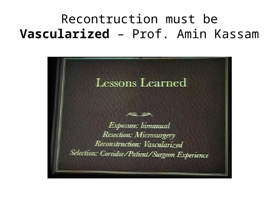
Recontruction must be Vascularized – Prof. Amin Kassam
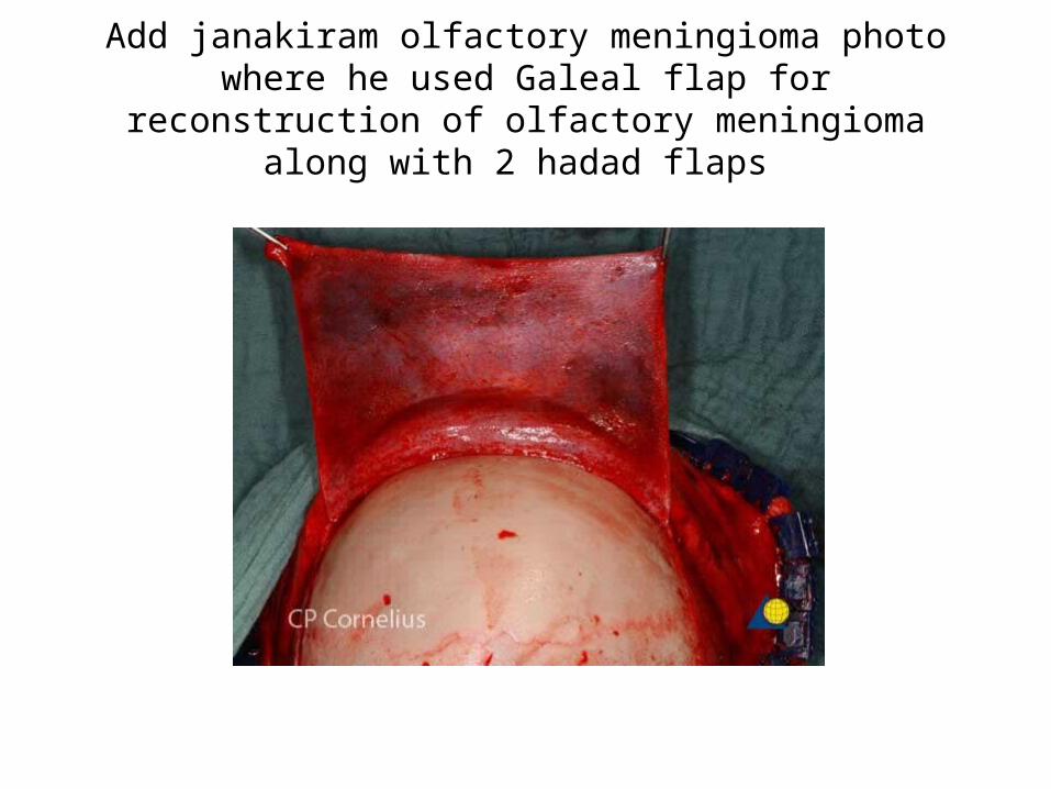
Add janakiram olfactory meningioma photo where he used Galeal flap for reconstruction of olfactory meningioma along
with 2 hadad flaps

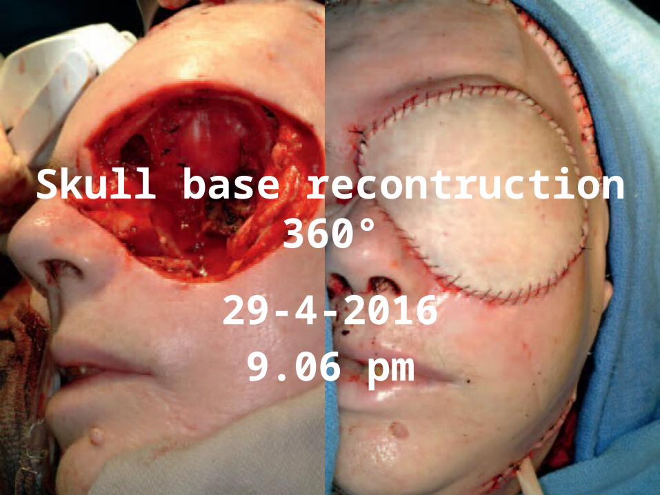
Figure 31.14 Combined ITF transorbital approach—I. This patient had a recurrent squamous cell carcinoma of the skin with invasion of the orbit. A. Planning of the
incisions. B. Superficial parotidectomy with preservation of the lower branches of the facial nerve and neck dissection.

FIGURE 46.4 Endonasal pericranial flap. A. A 5-cm coronal plane port with outlines for planned unilateral
endoscopically harvested pericranial flap. B. Dopplered supraorbital artery (SOA) and planned 3-cm pedicle. Nasion incision is shown in the concavity between the nasal and frontal bones. C. Transposed pericranial flap through the glabellar incision. Within the glabellar incision, the nasionectomy is
shown. D. Endoscopic view from the nasal side looking into the endonasal defect through the nasionectomy. E. Endoscopic endonasal view of a transcribriform defect resulting from resection of an esthesioneuroblastoma
from orbit to orbit and from planum to frontal sinus. F. Endoscopic view of pericranial flap skull base reconstruction of the defect (edges marked with dots) shown in (E).
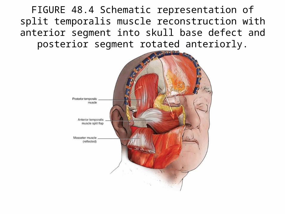
FIGURE 48.4 Schematic representation of split temporalis muscle reconstruction with anterior segment into skull base defect and
posterior segment rotated anteriorly.
http://www.ijps.org/article.asp?issn=0970-0358;year=2013;volume=46;issue=2;spage=239;epage=246;aulast=Jaju


Paul Gardner
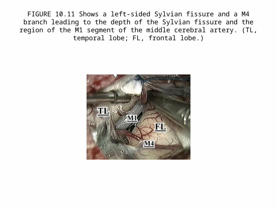
FIGURE 10.11 Shows a left-sided Sylvian fissure and a M4 branch leading to the depth of the Sylvian fissure and the region of the M1 segment of the middle cerebral artery.
(TL, temporal lobe; FL, frontal lobe.)

FIGURE 15.2 Coplanar surgery. The approach and target are on the same surgical plane.
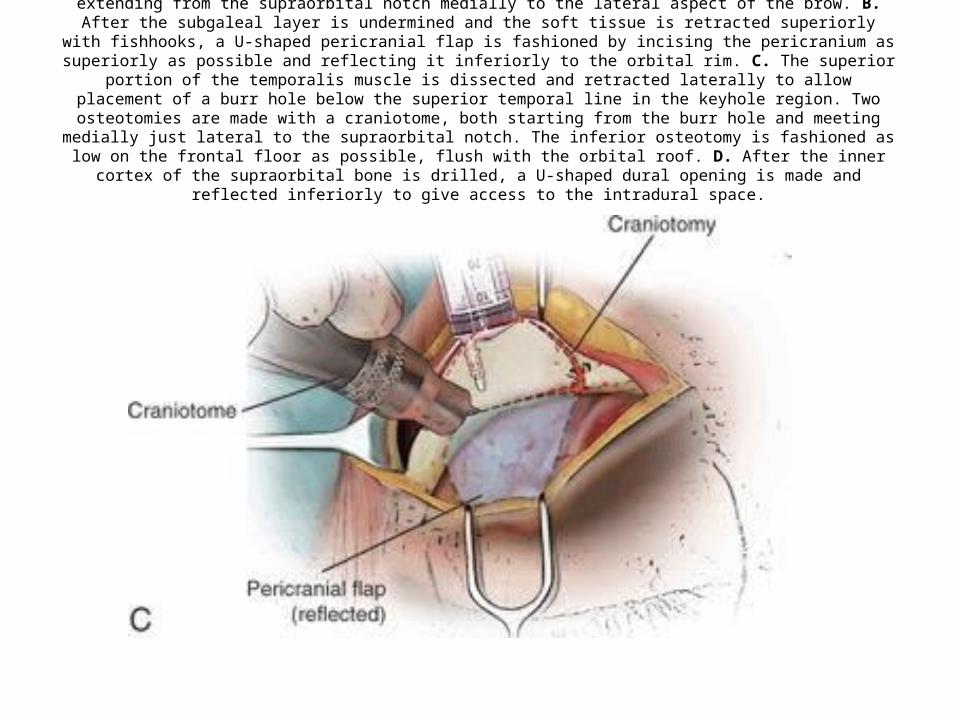
FIGURE 16.3 A. A skin incision is made within the eyebrow in its superior half, extending from the supraorbital notch medially to the lateral aspect of the brow. B. After the subgaleal layer is undermined and the soft tissue is retracted superiorly with fishhooks,
a U-shaped pericranial flap is fashioned by incising the pericranium as superiorly as possible and reflecting it inferiorly to the orbital rim. C. The superior portion of the temporalis muscle is dissected and retracted laterally to allow placement of a burr hole
below the superior temporal line in the keyhole region. Two osteotomies are made with a craniotome, both starting from the burr hole and meeting medially just lateral to the supraorbital notch. The inferior osteotomy is fashioned as low on the frontal
floor as possible, flush with the orbital roof. D. After the inner cortex of the supraorbital bone is drilled, a U-shaped dural opening is made and reflected inferiorly to give access to the intradural space.
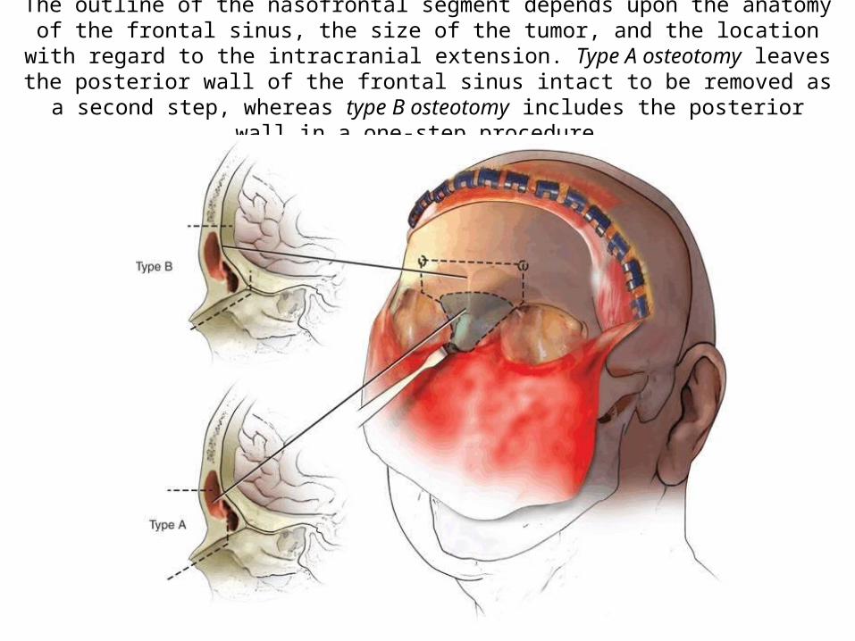
The outline of the nasofrontal segment depends upon the anatomy of the frontal sinus, the size of the tumor, and the location with regard to the intracranial extension. Type A
osteotomy leaves the posterior wall of the frontal sinus intact to be removed as a second step, whereas type B osteotomy includes the posterior wall in a one-step procedure.

FIGURE 28.2 Intraoperative, endoscopic endonasal view of the right vidian neurovascular bundle (VN) entering the vidian canal (VC), which has been drilled to the anterior genu of the petrous
internal carotid artery (ICA). Note that the vidian nerve runs lateral to the genu (just deep to the drill in this image), which lies just superior to the foramen lacerum (FL). (CR, clival recess.)
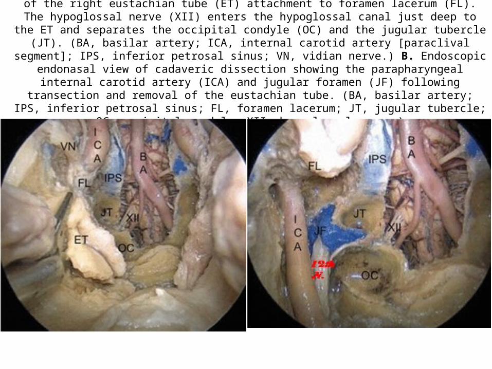
Endoscopic endonasal view of a cadaveric dissection showing transection of the right eustachian tube (ET) attachment to foramen lacerum (FL). The hypoglossal nerve (XII) enters the hypoglossal canal just deep to
the ET and separates the occipital condyle (OC) and the jugular tubercle (JT). (BA, basilar artery; ICA, internal carotid artery [paraclival segment]; IPS, inferior petrosal sinus; VN, vidian nerve.) B. Endoscopic
endonasal view of cadaveric dissection showing the parapharyngeal internal carotid artery (ICA) and jugular foramen (JF) following transection and removal of the eustachian tube. (BA, basilar artery; IPS, inferior petrosal sinus; FL, foramen lacerum; JT, jugular tubercle; OC, occipital condyle; XII, hypoglossal
nerve.)

FIGURE 30.2 A. Extradural bone removal from craniotomy, rongeur, and diamond bit drill. B. Right orbitozygomatic exposure after removing the bone flap. C. Exposure of the temporal–orbital band (dotted line) after removing the roof of the orbit and opening widely the superior orbital fissure.
D. Cutting the temporal–orbital band and peeling the outer layer of dura (lateral wall of the cavernous sinus) with the temporal lobe to expose the cavernous sinus and the cranial nerves.
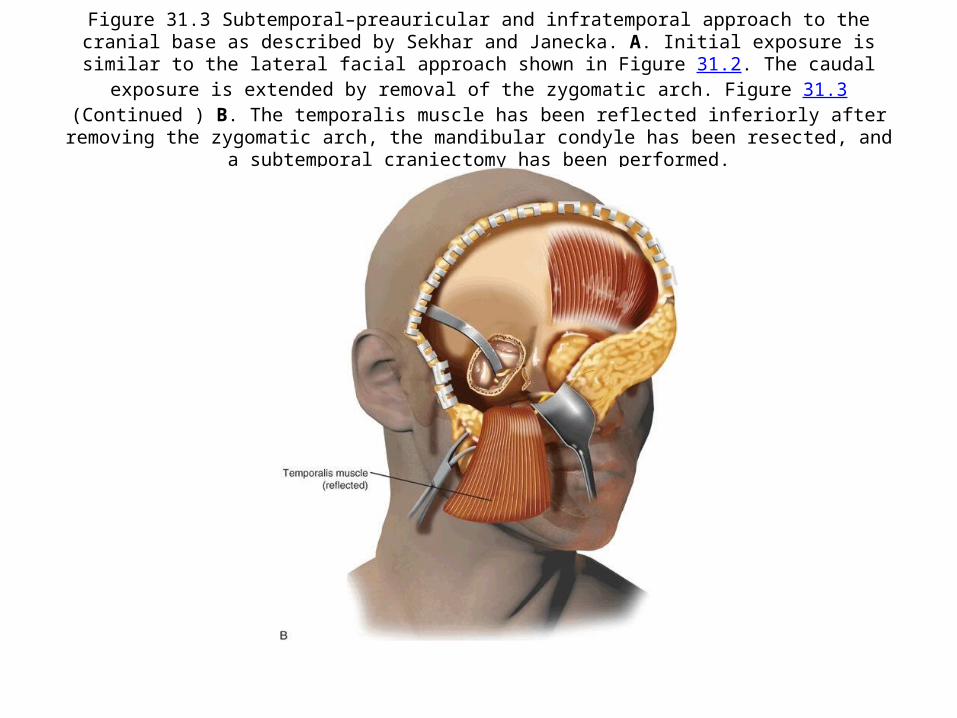
Figure 31.3 Subtemporal–preauricular and infratemporal approach to the cranial base as described by Sekhar and Janecka. A. Initial exposure is similar to the lateral facial approach shown in Figure 31.2. The caudal
exposure is extended by removal of the zygomatic arch. Figure 31.3(Continued ) B. The temporalis muscle has been reflected inferiorly after removing the zygomatic arch, the mandibular condyle has been resected, and a
subtemporal craniectomy has been performed.
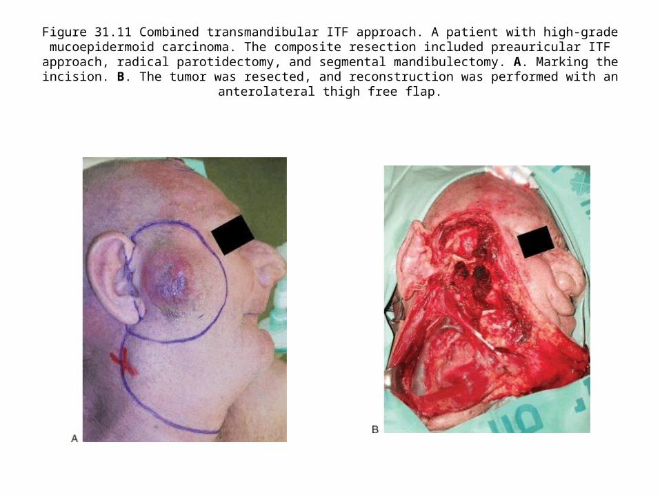
Figure 31.11 Combined transmandibular ITF approach. A patient with high-grade mucoepidermoid carcinoma. The composite resection included preauricular ITF approach, radical
parotidectomy, and segmental mandibulectomy. A. Marking the incision. B. The tumor was resected, and reconstruction was performed with an anterolateral thigh free flap.
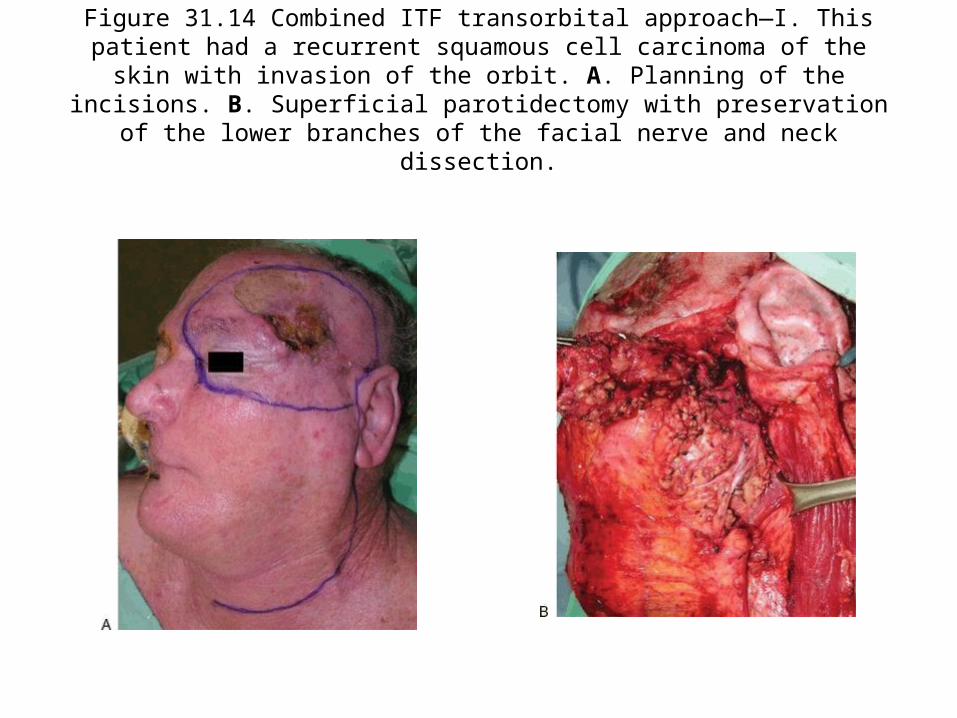
Figure 31.14 Combined ITF transorbital approach—I. This patient had a recurrent squamous cell carcinoma of the skin with invasion of the orbit. A. Planning of the
incisions. B. Superficial parotidectomy with preservation of the lower branches of the facial nerve and neck dissection.

FIGURE 34.2 A. Surgical anatomy of the right orbit. 1, frontozygomatic suture; 2, sphenozygomatic suture; 3, superior orbital fissure; 4, optic canal; 5, inferior orbital fissure; 6, foramen of infraorbital nerve. B. Outline of
bone removed through lateral orbitotomy: A, approach to MCF through greater wing of sphenoid bone; B, approach to infratemporal fossa. C. Region of approach through inferior orbitotomy. (MCF, middle cranial
fossa.)Figure 34.2(Continued ) D. Arrow on foramen rotundum seen through inferior orbital fissure.

Figure 35.5 Endoscopic endonasal view showing dissection of the dorsum sellae dura following intradural pituitary transposition. (PG, pituitary gland; ICA, internal carotid
artery.)
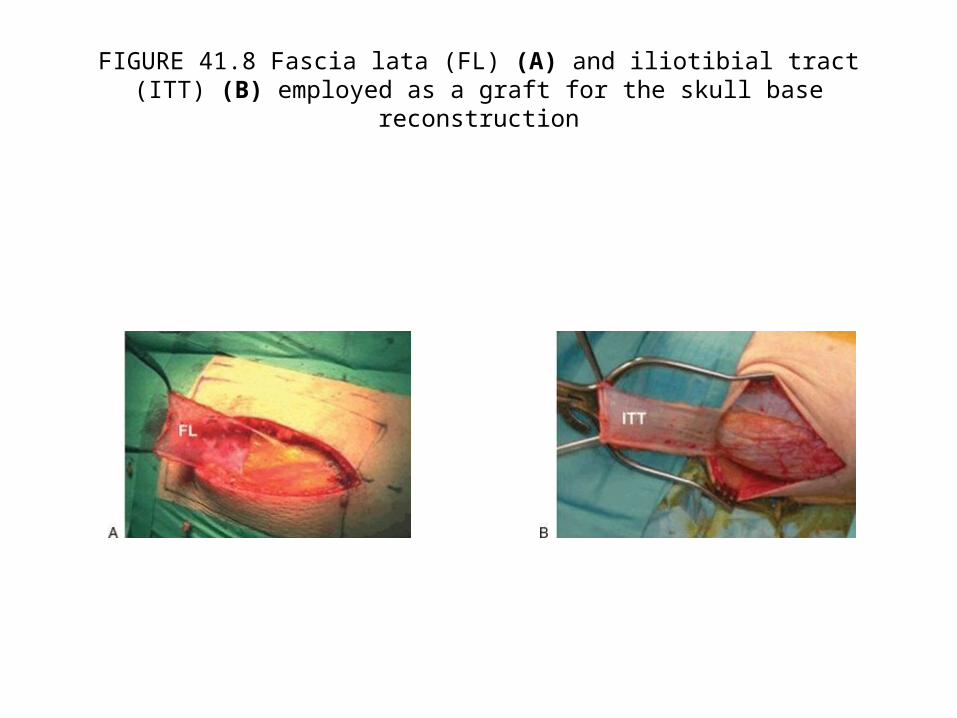
FIGURE 41.8 Fascia lata (FL) (A) and iliotibial tract (ITT) (B) employed as a graft for the skull base reconstruction
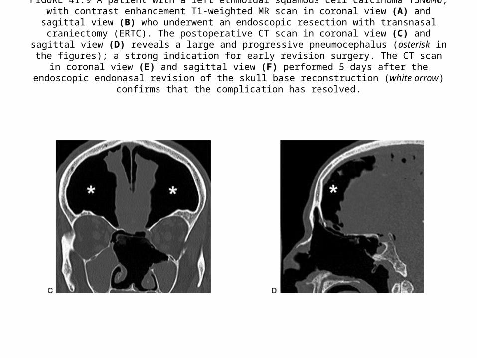
FIGURE 41.9 A patient with a left ethmoidal squamous cell carcinoma T3N0M0, with contrast enhancement T1-weighted MR scan in coronal view (A) and sagittal view (B) who underwent an endoscopic resection with
transnasal craniectomy (ERTC). The postoperative CT scan in coronal view (C) and sagittal view (D) reveals a large and progressive pneumocephalus (asterisk in the figures); a strong indication for early revision surgery.
The CT scan in coronal view (E) and sagittal view (F) performed 5 days after the endoscopic endonasal revision of the skull base reconstruction (white arrow) confirms that the complication has resolved.
Recontruction – separate PPT
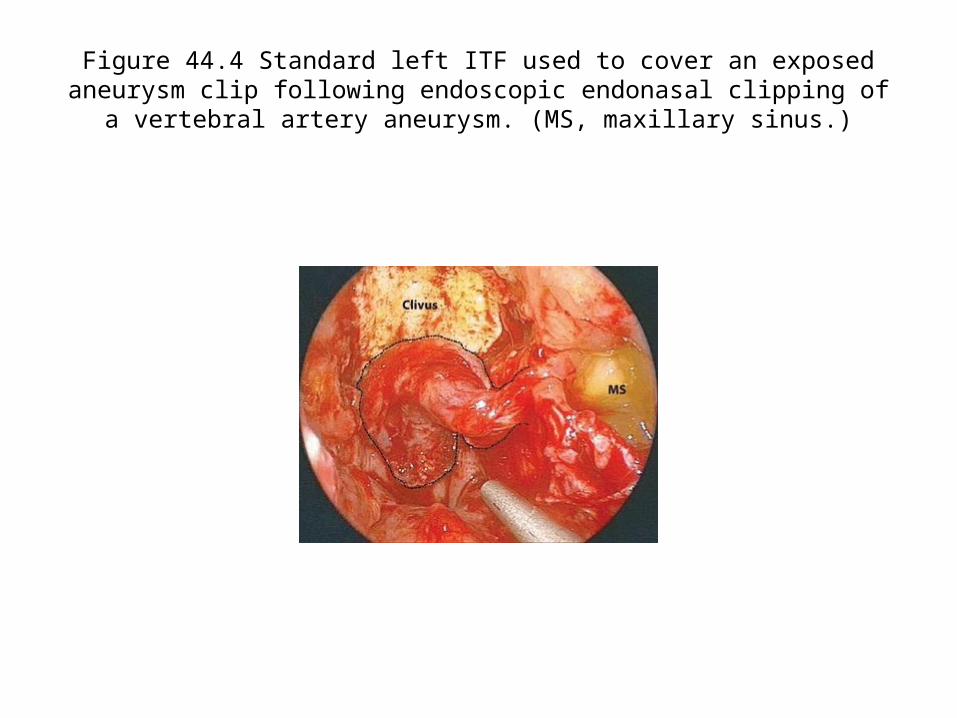
Figure 44.4 Standard left ITF used to cover an exposed aneurysm clip following endoscopic endonasal clipping of a vertebral artery aneurysm. (MS,
maxillary sinus.)
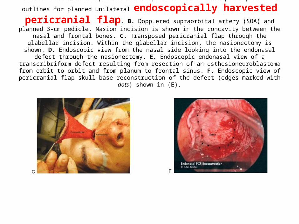
FIGURE 46.4 Endonasal pericranial flap. A. A 5-cm coronal plane port with outlines for planned unilateral
endoscopically harvested pericranial flap. B. Dopplered supraorbital artery (SOA) and planned 3-cm pedicle. Nasion incision is shown in the concavity between the nasal and frontal bones. C. Transposed pericranial flap through the glabellar incision. Within the glabellar incision, the nasionectomy is
shown. D. Endoscopic view from the nasal side looking into the endonasal defect through the nasionectomy. E. Endoscopic endonasal view of a transcribriform defect resulting from resection of an esthesioneuroblastoma
from orbit to orbit and from planum to frontal sinus. F. Endoscopic view of pericranial flap skull base reconstruction of the defect (edges marked with dots) shown in (E).

FIGURE 48.4 Schematic representation of split temporalis muscle reconstruction with anterior segment into skull base defect and
posterior segment rotated anteriorly.

For Other powerpoint presentatioins of “ Skull base 360° ”
I will update continuosly with date tag at the end as I am getting more & more information
click
www.skullbase360.in - you have to login to slideshare.net with Facebook account after clicking www.skullbase360.in