
Sizing, Installation, Dimensions and Weights - Swegon handling units/GOLD version F... · Exact...
59
20171101 We reserve the right to alter specifications. GOLD 19 Prerequisites for Sizing ..................................................................................................... 21 GOLD RX, One-piece air handling units with rotary heat exchanger ........................... 22 GOLD PX, One-piece air handling units with plate heat exchanger ............................. 78 GOLD CX, One-piece air handling units with coil heat exchanger.............................. 110 GOLD SD, Supply air and extract air handling units .................................................... 126 Sizing, Installation, Dimensions and Weights Contents The charts and tables in this documentation are intended for use as a general survey. Exact sizing can be carried out in the AHU Design air handling unit selection program.
Transcript of Sizing, Installation, Dimensions and Weights - Swegon handling units/GOLD version F... · Exact...

20171101 We reserve the right to alter specifications.
GOLD
19
Prerequisites for Sizing ..................................................................................................... 21GOLD RX, One-piece air handling units with rotary heat exchanger ........................... 22GOLD PX, One-piece air handling units with plate heat exchanger ............................. 78GOLD CX, One-piece air handling units with coil heat exchanger .............................. 110GOLD SD, Supply air and extract air handling units .................................................... 126
Sizing, Installation, Dimensions and Weights
Contents
The charts and tables in this documentation are intended for use as a general survey.
Exact sizing can be carried out in the AHU Design air handling
unit selection program.

GOLD
We reserve the right to alter specifications. 2017110120

20171101 We reserve the right to alter specifications.
GOLD
21
Acoustic calculationsThe sound emitted by Swegon products is measured accord-ing to the method defined in ISO 5136, the most widely used method in Europe. Acoustic measurements are sometimes taken using other methods.
The total sound power level LW, tot emitted from the fan outlet to the ducting can be read from each of the fan diagrams. The following formula can be used for breaking down the total sound power level into octave bands: LW, ok = LW, tot + Kok.
Kok can be obtained from tables on the pages that follow.
Fan DiagramsThe SFPV diagram on the pages that follow shows the elec-tric power efficiency rating of the air handling unit calculated according to the procedure defined by SwedVent, the Swedish Association of Air handling Industries (V Publication 1995:1, Rev. 2000). The SFPV-value is calculated according to the V publication under the load conditions that exist when the air filters are clean.
GOLD RX/PX/CX The SFPV diagrams and Extract air fan are calculated with the assumption that the supply air and extract air fans have the same airflow and available total pressure rise. The leakage and purging air flow and the extra pressure drop in the extract air have been taken into consideration in order to ensure the cor-rect direction of air leakage at a pressure ratio that corresponds to a normal installation for a certain available pressure.
The Extract air fan and Supply air fan diagrams indicate the available total pressure rise to cover duct pressure drop and external functional sections, and total sound power level, LW, tot emitted to a connecting outlet duct, dB (relative to 10-12 W), in the 125 – 8,000 Hz octave band frequencies.
The available pressure rise calculated for the design pressure drop across the ePM1 50% (F7) filter (supply air) and the ePM10 60% (M5) filter (extract air) respectively and with full face end connection panels (accessories) is specified in all the diagrams.
The blue broken line defines the limits of the numbered ranges (1,2,3,4) for particulars of the correction factors KOK in a separate table. Range 1 is the most favourable range from an acoustic point of view.
GOLD SDThe Fan Charts indicate the total pressure rise to cover pos-sible internal total pressure losses for, e.g. filters, duct pressure drop and external functional sections, and total sound power level LW, tot emitted to a connecting outlet duct, dB (relative to 10 -12 W), in the 125 – 8,000 Hz octave band frequencies. The diagrams show air handling units with full face end connection panels (accessories).
The total pressure loss for an optional filter, ePM1 50% (F7)/ePM10 60% (M5), and coil heat exchangers (sizes 014-80) are specified in the lower diagram.
The blue broken line defines the limits of the numbered ranges (1,2,3,4) for particulars of the correction factors KOK in a separate table. Range 1 is the most favourable range from an acoustic point of view.
Prerequisites for Sizing
Sizing, Installation, Dimensions and Weights

GOLD
We reserve the right to alter specifications. 2017110122
Sizing, Installation, Dimensions and Weights
Min. and Max. AirflowsThe flows specified refer to those that can be preset in the hand-held micro terminal. The practical flow limits are deter-mined by the external pressure drop.
* The integral attenuation of filters and rotary heat exchanger has been taken into account. ** Total sound power level emitted to the surroundings is calcu-lated as the sum of the levels in the supply air and the extract air.
Correction factors KOK , dB
Size Min. airflow (on airflow regulation)
Max. airflow
m3/h m3/s m3/h m3/s004 288 0.08 1620 0.45
Range in the
diagram
Octave band, No. / mid-frequency, Hz
Sound path 1 2 3 4 5 6 7 8
63 125 250 500 1000 2000 4000 8000
To outlet duct 1 -1 -6 -6 -8 -7 -7 -12 -152 -1 -5 -8 -8 -7 -9 -13 -163 -1 -2 -6 -15 -14 -16 -22 -254 -2 -3 -5 -13 -13 -14 -20 -25
To inlet duct* 1 -6 -9 -12 -22 -31 -33 -38 -372 -7 -10 -17 -18 -29 -31 -37 -383 -6 -4 -14 -27 -35 -39 -44 -434 -7 -5 -12 -22 -34 -36 -42 -43
To air handling unit surroun-dings**
1 -12 -20 -29 -29 -40 -40 -46 -462 -12 -19 -31 -29 -40 -42 -47 -473 -12 -16 -29 -36 -47 -49 -56 -564 -13 -17 -28 -34 -46 -47 -54 -56
2.5
2.0
1.5
1
23
4
123
4
70dB 75Lw,tot
8085
70dB 75Lw,tot
8085
Supply air fan
Extract air fan
SFPv
Air flow, m3/s
Ava
ilab
le t
ota
l pre
ssu
re r
ise,
Pa
Air flow, m3/h
Recommended working range for sizing.
Permissible operating range when the fan is controlled to operate at a lower speed. The lower limit for the air flow when the unit is operating in the air flow regulation mode; see the black broken line in the diagram. If pressure regulation is used, the air flow can be regulated to zero, however this presupposes a certain static pressure drop in the ducting (approx. 50 Pa).
The air handling unit complies with requirements to Ecodesign 2016/2018.
The lower limit for the air flow when the unit is operating in the air flow regulation mode.
GOLD RX, rotary heat exchanger, size 004, common casing

20171101 We reserve the right to alter specifications.
GOLD
23
Sizing, Installation, Dimensions and Weights
Power connection1-phase, 3-wire, 230 V -10/+15%, 50 Hz, 10 A or 3-phase, 5-wire, 400 V -10/+15%, 50 Hz, 10 A
Rated data per fanMotor shaft power: 0.8 kW (0.41 kW)* motor control system, 1 x 230 V, 50 Hz *The motor control system limits the power of the take-off to the value specified.
Clear Space for InspectionA clear space of 800 mm must be provided in front of the unit and at least 200 mm must be provided above the junction hood.
Right-hand version
Left-hand version
Delivery and Transport within the SiteThe GOLD RX 004 is produced in one single variant. All of its components are arranged at their given physical location inside the air handling unit. The air handling unit is supplied on a wooden pallet.
Prefitted base beams are obtainable as optional equipment; a separately supplied stand is available as an accessory.
Duct connection optionsA: Specify right-hand or left-hand version when ordering! If the air handling unit is supplied with all the end connection panels, the version can be changed at the building site by selecting the appropriate version in the hand-held micro terminal.
B: The air handling unit can be installed up ended (does not apply to units installed outdoors).
C: Specify upper fan outlet for upward air discharge when plac-ing orders (Does not apply to units installed outdoors). N.B.! Duct connection size: ø 400 mm.
D: Specify whether the unit shall have an air intake from above for outdoor air or extract air when placing orders (Does not apply to units installed outdoors).
Outside air Supply air Extract air Exhaust air
52
284 284
380 18
76 76
45 45J
14ø 400 ø 315
= =
Size A B C D F G H J L Ø Weight, kg
004 743 825 240 345 230 460 920 579 1499 315 234-271
Power connection
The base beams are optional. * If duct accessories are inside an insulated casing, the air handling unit is supplied without end connection panel. The AHU can also be supplied with full face end connection panel (accessory).
GOLD RX, rotary heat exchanger, size 004, common casing

GOLD
We reserve the right to alter specifications. 2017110124
GOLD RX, rotary heat exchanger, size 004, split version
Sizing, Installation, Dimensions and Weights
Min. and Max. AirflowsThe flows specified refer to those that can be preset in the hand-held micro terminal. The practical flow limits are deter-mined by the external pressure drop.
* The integral attenuation of filters and rotary heat exchanger has been taken into account. ** Total sound power level emitted to the surroundings is calcu-lated as the sum of the levels in the supply air and the extract air.
Correction factors KOK , dB
Size Min. airflow (on airflow regulation)
Max. airflow
m3/h m3/s m3/h m3/s004 288 0.08 1620 0.45
Range in the
diagram
Octave band, No. / mid-frequency, Hz
Sound path 1 2 3 4 5 6 7 8
63 125 250 500 1000 2000 4000 8000
To outlet duct 1 -1 -6 -6 -8 -7 -7 -12 -152 -1 -5 -8 -8 -7 -9 -13 -163 -1 -2 -6 -15 -14 -16 -22 -254 -2 -3 -5 -13 -13 -14 -20 -25
To inlet duct* 1 -6 -9 -12 -22 -31 -33 -38 -372 -7 -10 -17 -18 -29 -31 -37 -383 -6 -4 -14 -27 -35 -39 -44 -434 -7 -5 -12 -22 -34 -36 -42 -43
To air handling unit surroun-dings**
1 -12 -20 -29 -29 -40 -40 -46 -462 -12 -19 -31 -29 -40 -42 -47 -473 -12 -16 -29 -36 -47 -49 -56 -564 -13 -17 -28 -34 -46 -47 -54 -56
2.5
2.0
1.5
1
23
4
123
4
70dB 75Lw,tot
8085
70dB 75Lw,tot
8085
Supply air fan
Extract air fan
SFPv
Air flow, m3/s
Ava
ilab
le t
ota
l pre
ssu
re r
ise,
Pa
Air flow, m3/h
Recommended working range for sizing.
Permissible operating range when the fan is controlled to operate at a lower speed. The lower limit for the air flow when the unit is operating in the air flow regulation mode; see the black broken line in the diagram. If pressure regulation is used, the air flow can be regulated to zero, however this presupposes a certain static pressure drop in the ducting (approx. 50 Pa).
The air handling unit complies with requirements to Ecodesign 2016/2018.
The lower limit for the air flow when the unit is operating in the air flow regulation mode.

20171101 We reserve the right to alter specifications.
GOLD
25
45 45J5252
45 45J
K
7676
K
14380 18ø 400 ø 315
= =
284 284
GOLD RX, rotary heat exchanger, size 004, split version
Sizing, installation, dimensions and weights
Power connection1-phase, 3-wire, 230 V -10/+15%, 50 Hz, 10 A or 3-phase, 5-wire, 400 V -10/+15%, 50 Hz, 10 A
Rated data per fanMotor shaft power 0.8 kW (0.41 kW)*, Motor control system: 1 x 230 V, 50 Hz *The motor control system limits the output power to the value speci-fied.
Delivery and transport within the siteThe GOLD RX 004 can be supplied as one single unit, or in a number of different combinations of unit sections from the factory, see the section: Description of the Air Handling Unit/Delivery Configuration RX/PX/CX, sizes 004-080. Prefitted base beams as standard. The unit sections are jointed together/split by means of bolts. The electrical and control cables between the unit sections have quick-fit connectors.
Duct connection optionsA: Specify right-hand or left-hand version when ordering. If the air handling unit is supplied with all the end connection panels, the version can be changed at the building site using the hand-held terminal.B: The arrangement of the functional sections can be vertically reversed. To be specified when placing an order, see the illustra-tion to the right.C: Specify upper fan outlet for upward air discharge when plac-ing orders (Does not apply to units installed outdoors). N.B.! Duct connection size: ø 400 mm.D: Specify whether the unit shall have an air intake from above for outdoor air or extract air when placing orders (Does not apply to units installed outdoors).
Power connection
Size A B C D F G H J K L Ø Weight, kg
004 617 825 240 565 230 460 920 579 345 1799 315 278-328
The unit can be divided into three sections at the building site.Dimensions: See A and D in the table above.Weight: A = 88-112 kg, D = 102-104 kg.
Division into sections for transport
A AD
Clear space for inspectionA clear space of 800 mm should be provided in front of the unit and at least 200 mm should be provided above the junction hood.
Right-hand version
Left-hand version
Supply air fan, right, lower level
Supply air fan, right, upper level
Supply air fan, left, upper level
Supply air fan, left, lower level
Outdoor air Supply air Extract air Exhaust air
The illustration shows the connections for supply air fan, right-hand/lower level and left-hand/upper level. For supply air fan, right-hand/upper level and left-hand/lower level, the connections are mirror-inverted.* The air handling unit is supplied without end connection panel if a duct accessory housed in an insulated casing will be connected. The AHU can also be supplied with full face end connection panel (accessory).
GOLD
We reserve the right to alter specifications. 2017110126
GOLD RX Top, rotary heat exchanger, size 004
Sizing, Installation, Dimensions and Weights
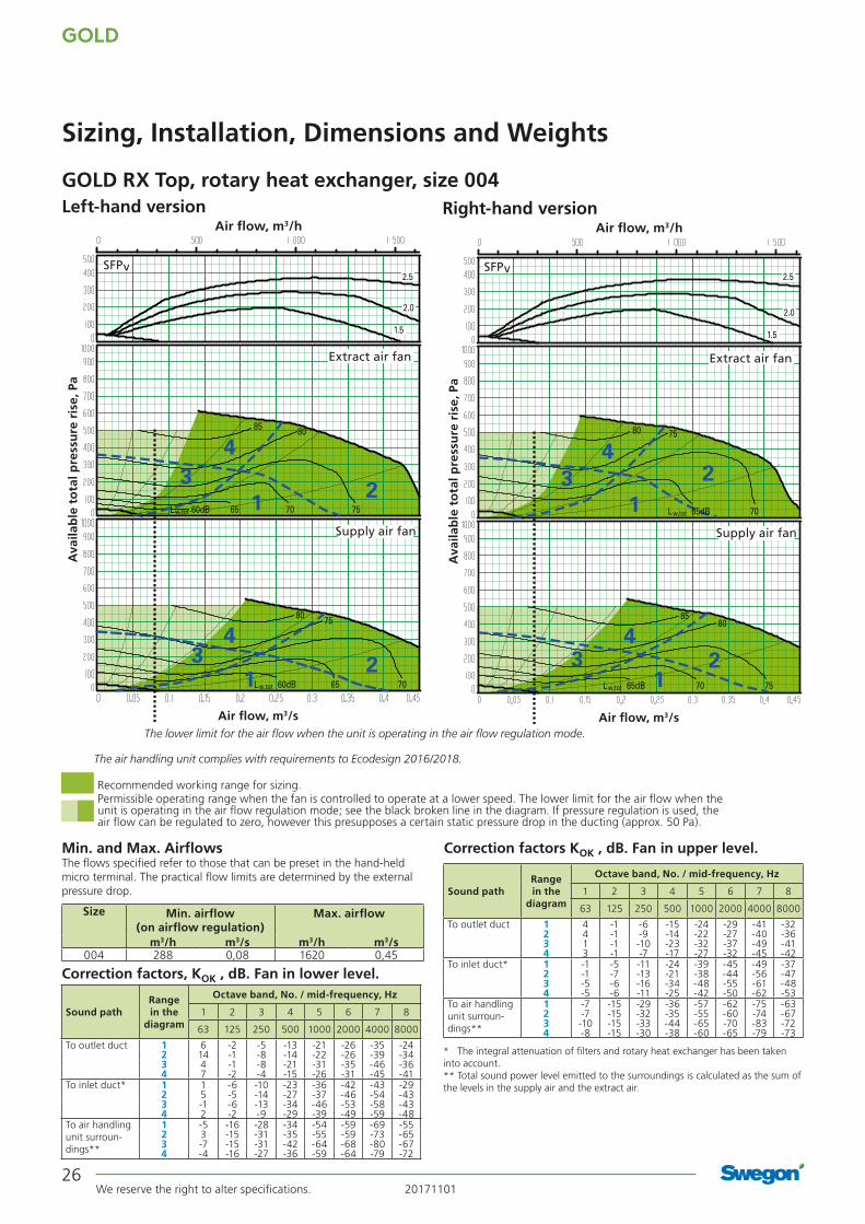
Min. and Max. AirflowsThe flows specified refer to those that can be preset in the hand-held micro terminal. The practical flow limits are determined by the external pressure drop.
* The integral attenuation of filters and rotary heat exchanger has been taken into account.** Total sound power level emitted to the surroundings is calculated as the sum of the levels in the supply air and the extract air.
Correction factors KOK , dB. Fan in upper level.
Size Min. airflow (on airflow regulation)
Max. airflow
m3/h m3/s m3/h m3/s004 288 0,08 1620 0,45
Range in the
diagram
Octave band, No. / mid-frequency, Hz
Sound path 1 2 3 4 5 6 7 8
63 125 250 500 1000 2000 4000 8000
To outlet duct 1 4 -1 -6 -15 -24 -29 -41 -322 4 -1 -9 -14 -22 -27 -40 -363 1 -1 -10 -23 -32 -37 -49 -414 3 -1 -7 -17 -27 -32 -45 -42
To inlet duct* 1 -1 -5 -11 -24 -39 -45 -49 -372 -1 -7 -13 -21 -38 -44 -56 -473 -5 -6 -16 -34 -48 -55 -61 -484 -5 -6 -11 -25 -42 -50 -62 -53
To air handling unit surroun-dings**
1 -7 -15 -29 -36 -57 -62 -75 -632 -7 -15 -32 -35 -55 -60 -74 -673 -10 -15 -33 -44 -65 -70 -83 -724 -8 -15 -30 -38 -60 -65 -79 -73
Range in the
diagram
Octave band, No. / mid-frequency, Hz
Sound path 1 2 3 4 5 6 7 8
63 125 250 500 1000 2000 4000 8000
To outlet duct 1 6 -2 -5 -13 -21 -26 -35 -242 14 -1 -8 -14 -22 -26 -39 -343 4 -1 -8 -21 -31 -35 -46 -364 7 -2 -4 -15 -26 -31 -45 -41
To inlet duct* 1 1 -6 -10 -23 -36 -42 -43 -292 5 -5 -14 -27 -37 -46 -54 -433 -1 -6 -13 -34 -46 -53 -58 -434 2 -2 -9 -29 -39 -49 -59 -48
To air handling unit surroun-dings**
1 -5 -16 -28 -34 -54 -59 -69 -552 3 -15 -31 -35 -55 -59 -73 -653 -7 -15 -31 -42 -64 -68 -80 -674 -4 -16 -27 -36 -59 -64 -79 -72
Correction factors, KOK , dB. Fan in lower level.
Left-hand version Right-hand version
123
4
Lw,tot 60dB 65 70
Lw,tot 6560dB 70 75
85 80
2.5
2.0
1.5
1 23
4
7580
Supply air fan
Extract air fan
SFPv
Air flow, m3/s
Ava
ilab
le t
ota
l pre
ssu
re r
ise,
Pa
Air flow, m3/h
The lower limit for the air flow when the unit is operating in the air flow regulation mode.
75
Lw,tot
2.5
2.0
1.5
123
4
123
4
80
65dB 70 75Lw,tot
8085
65dB 70
Supply air fan
Extract air fan
SFPv
Air flow, m3/s
Ava
ilab
le t
ota
l pre
ssu
re r
ise,
Pa
Air flow, m3/h
Recommended working range for sizing.Permissible operating range when the fan is controlled to operate at a lower speed. The lower limit for the air flow when the unit is operating in the air flow regulation mode; see the black broken line in the diagram. If pressure regulation is used, the air flow can be regulated to zero, however this presupposes a certain static pressure drop in the ducting (approx. 50 Pa).
The air handling unit complies with requirements to Ecodesign 2016/2018.

20171101 We reserve the right to alter specifications.
GOLD
27
GOLD RX Top, rotary heat exchanger, size 004
Sizing, Installation, Dimensions and Weights
Power connection1-phase, 3-wire, 230 V -10/+15%, 50 Hz, 10 A or 3-phase, 5-wire, 400 V -10/+15%, 50 Hz, 10 A
Rated data per fanMotor shaft power: 0.8 kW (0.41 kW)* motor control system, 1 x 230 V, 50 Hz *The motor control system limits the power of the take-off to the value specified.
Clear Space for InspectionA clear space of 800 mm must be provided in front of the unit and at least 200 mm must be provided above the junction hood.
Delivery and Transport within the SiteThe GOLD RX Top 004 is produced in one single variant. All of its components are arranged at their given physical location inside the air handling unit. The GOLD RX Top 004 is always supplied as one unit. The air handling unit is supplied on a wooden pallet.
Prefitted base beams are obtainable as optional equipment; a separately supplied stand is available as an accessory.
Duct connection optionsA: All the duct connections are arranged from the top of the air handling unit (the unit must not be installed outdoors).
B: The air handling unit is supplied in the right-hand version. The unit can be changed to the left-hand version at the building site by selecting the appropriate version in the hand-held micro terminal.
Outside air Supply air Extract air Exhaust air
Left-hand version Right-hand version
45 45J5252
380 18
7614
Size A B C D F G H J L Ø Weight, kg
004 743 825 233,5 1033 237,5 350 920 579 1499 315 269
Power connectionBase beams are optional.

GOLD
We reserve the right to alter specifications. 2017110128
Recommended working range for sizing.Permissible operating range when the fan is controlled to operate at a lower speed. The lower limit for the airflow when the unit is operating in the airflow regulation mode; see the black broken line in the diagram. If pressure regulation is used, the airflow can be regulated to zero, however this presupposes a certain static pressure drop in the ducting (approx. 50 Pa).
Limit line, Ecodesign, 2016 Limit line, Ecodesign, 2018
Min. and Max. AirflowsThe flows specified refer to those that can be preset in the hand-held micro terminal. The practical flow limits are deter-mined by the external pressure drop.
Correction factors KOK , dB
Sizing, Installation, Dimensions and Weights
Size Min. airflow (on airflow regulation)
Max. airflow
m3/h m3/s m3/h m3/s005 288 0.08 2340 0.65
* The integral attenuation of filters and rotary heat exchanger has been taken into account. ** Total sound power level emitted to the surroundings is calcu-lated as the sum of the levels in the supply air and the extract air.
Range in the
diagram
Octave band, No. / mid-frequency, Hz
Sound path 1 2 3 4 5 6 7 8
63 125 250 500 1000 2000 4000 8000
To outlet duct 1 -1 -6 -6 -8 -7 -7 -12 -152 -1 -5 -8 -8 -7 -9 -13 -163 -1 -2 -6 -15 -14 -16 -22 -254 -2 -3 -5 -13 -13 -14 -20 -25
To inlet duct* 1 -6 -9 -12 -22 -31 -33 -38 -372 -7 -10 -17 -18 -29 -31 -37 -383 -6 -4 -14 -27 -35 -39 -44 -434 -7 -5 -12 -22 -34 -36 -42 -43
To unit’s sur-roundings**
1 -12 -20 -29 -29 -40 -40 -46 -462 -12 -19 -31 -29 -40 -42 -47 -473 -12 -16 -29 -36 -47 -49 -56 -564 -13 -17 -28 -34 -46 -47 -54 -56
GOLD RX, rotary heat exchanger, size 005, common casing
2.5
2.01.5
1
2
4
1
23
4
70dB 75 80
85
Lw,tot
90
70dB 75 80
85
Lw,tot
9095
3
Supply air fan
Extract air fan
SFPv
Air flow, m3/s
Ava
ilab
le t
ota
l pre
ssu
re r
ise,
Pa
Air flow, m3/h
The lower limit for the air flow when the unit is operating in the air flow regulation mode.
Cap. var. 1
Cap. var. 2
Cap. var. 1
Cap. var. 2
The limit lines for Ecodesign are calculated with capacity variant 2. The mean value for supply air and extract air must be within the limit line.

20171101 We reserve the right to alter specifications.
GOLD
29
Clear Space for InspectionA clear space of 800 mm must be provided in front of the unit and at least 200 mm must be provided above the junction hood.
Right-hand version
Left-hand version
Delivery and Transport within the SiteThe GOLD RX 005 is produced in one single variant, in which all the components are arranged at their given physical locations inside the air handling unit. The air handling unit is supplied on a wooden pallet.
Prefitted base beams are obtainable as optional equipment; a separately supplied stand is available as an accessory.
Duct connection optionsA: Specify right-hand or left-hand version when ordering! If the air handling unit is supplied with all the end connection panels, the version can be changed at the building site by selecting the appropriate version in the hand-held micro terminal.
B: The air handling unit can be installed up ended (does not apply to units installed outdoors).
C: Specify upper fan outlet for upward air discharge when plac-ing orders (Does not apply to units installed outdoors). N.B.! Duct connection size: ø 400 mm.
D: Specify whether the unit shall have an air intake from above for outdoor air or extract air when placing orders (Does not apply to units installed outdoors).
Outside air Supply air Extract air Exhaust air
Sizing, Installation, Dimensions and Weights
Power connection1-phase, 3-wire, 230 V -10/+15%, 50 Hz, 10 A (capacity variant 1) alt. 16 A (capacity variant 2) or 3-phase, 5-wire, 400 V -10/+15%, 50 Hz, 10 A
Rated data per fanMotor shaft power: 0.8 kW alt. 1.15 kW, motor control system: 1 x 230 V, 50 Hz
52
284 284
380 18
76 76
45 45J
14ø 400 ø 315
= =
Size A B C D F G H J L Ø Weight, kg
005 743 825 240 345 230 460 920 579 1499 315 234-271
Power connection
The base beams are optional. * If duct accessories are inside an insulated casing, the air handling unit is supplied without end connection panel. The AHU can also be supplied with full face end connection panel (accessory).
GOLD RX, rotary heat exchanger, size 005, common casing

GOLD
We reserve the right to alter specifications. 2017110130
GOLD RX, rotary heat exchanger, size 005, split version
Recommended working range for sizing.Permissible operating range when the fan is controlled to operate at a lower speed. The lower limit for the airflow when the unit is operating in the airflow regulation mode; see the black broken line in the diagram. If pressure regulation is used, the airflow can be regulated to zero, however this presupposes a certain static pressure drop in the ducting (approx. 50 Pa).
Limit line, Ecodesign, 2016 Limit line, Ecodesign, 2018
Min. and Max. AirflowsThe flows specified refer to those that can be preset in the hand-held micro terminal. The practical flow limits are deter-mined by the external pressure drop.
Correction factors KOK , dB
Sizing, Installation, Dimensions and Weights
Size Min. airflow (on airflow regulation)
Max. airflow
m3/h m3/s m3/h m3/s005 288 0.08 2340 0.65
* The integral attenuation of filters and rotary heat exchanger has been taken into account. ** Total sound power level emitted to the surroundings is calcu-lated as the sum of the levels in the supply air and the extract air.
Range in the
diagram
Octave band, No. / mid-frequency, Hz
Sound path 1 2 3 4 5 6 7 8
63 125 250 500 1000 2000 4000 8000
To outlet duct 1 -1 -6 -6 -8 -7 -7 -12 -152 -1 -5 -8 -8 -7 -9 -13 -163 -1 -2 -6 -15 -14 -16 -22 -254 -2 -3 -5 -13 -13 -14 -20 -25
To inlet duct* 1 -6 -9 -12 -22 -31 -33 -38 -372 -7 -10 -17 -18 -29 -31 -37 -383 -6 -4 -14 -27 -35 -39 -44 -434 -7 -5 -12 -22 -34 -36 -42 -43
To unit’s sur-roundings**
1 -12 -20 -29 -29 -40 -40 -46 -462 -12 -19 -31 -29 -40 -42 -47 -473 -12 -16 -29 -36 -47 -49 -56 -564 -13 -17 -28 -34 -46 -47 -54 -56
2.5
2.01.5
1
2
4
1
23
4
70dB 75 80
85
Lw,tot
90
70dB 75 80
85
Lw,tot
9095
3
Supply air fan
Extract air fan
SFPv
Air flow, m3/s
Ava
ilab
le t
ota
l pre
ssu
re r
ise,
Pa
Air flow, m3/h
The lower limit for the air flow when the unit is operating in the air flow regulation mode.
Cap. var. 1
Cap. var. 2
Cap. var. 1
Cap. var. 2
The limit lines for Ecodesign are calculated with capacity variant 2. The mean value for supply air and extract air must be within the limit line.

20171101 We reserve the right to alter specifications.
GOLD
31
GOLD RX, rotary heat exchanger, size 005, split version
Sizing, installation, dimensions and weights
Delivery and transport within the siteThe GOLD RX 005 can be supplied as one single unit, or in a number of different combinations of unit sections from the factory, see the section: Description of the Air Handling Unit/Delivery Configuration RX/PX/CX, sizes 004-080. Prefitted base beams as standard. The unit sections are jointed together/split by means of bolts. The electrical and control cables between the unit sections have quick-fit connectors.
Duct connection optionsA: Specify right-hand or left-hand version when ordering. If the air handling unit is supplied with all the end connection panels, the version can be changed at the building site using the hand-held terminal.B: The arrangement of the functional sections can be vertically reversed. To be specified when placing an order, see the illustra-tion to the right.C: Specify upper fan outlet for upward air discharge when plac-ing orders (Does not apply to units installed outdoors). N.B.! Duct connection size: ø 400 mm.D: Specify whether the unit shall have an air intake from above for outdoor air or extract air when placing orders (Does not apply to units installed outdoors).
Size A B C D F G H J K L Ø Weight, kg
005 617 825 240 565 230 460 920 579 345 1799 315 278-328
The unit can be divided into three sections at the building site.Dimensions: See A and D in the table above.Weight: A = 88-112 kg, D = 102-104 kg.
Division into sections for transport
A AD
Clear space for inspectionA clear space of 800 mm should be provided in front of the unit and at least 200 mm should be provided above the junction hood.
Power connection1-phase, 3-wire, 230 V -10/+15%, 50 Hz, 10 A (capacity variant 1) or 16 A (capacity variant 2) or 3-phase, 5-wire, 400 V -10/+15%, 50 Hz, 10 A
Rated data per fanMotor shaft power: 0.8 kW alt. 1.15 kW, motor control system: 1 x 230 V, 50 Hz
Right-hand version
Left-hand version
Supply air fan, right, lower level
Supply air fan, right, upper level
Supply air fan, left, upper level
Supply air fan, left, lower level
Outdoor air Supply air Extract air Exhaust air
45 45J5252
45 45J
K
7676
K
14380 18ø 400 ø 315
= =
284 284
Power connection
The illustration shows the connections for supply air fan, right-hand/lower level and left-hand/upper level. For supply air fan, right-hand/upper level and left-hand/lower level, the connections are mirror-inverted.* The air handling unit is supplied without end connection panel if a duct accessory housed in an insulated casing will be connected. The AHU can also be supplied with full face end connection panel (accessory).

GOLD
We reserve the right to alter specifications. 2017110132
GOLD RX Top, rotary heat exchanger, size 005
Sizing, Installation, Dimensions and Weights
Recommended working range for sizing.Permissible operating range when the fan is controlled to operate at a lower speed. The lower limit for the airflow when the unit is operating in the airflow regulation mode; see the black broken line in the diagram. If pressure regulation is used, the airflow can be regulated to zero, however this presupposes a certain static pressure drop in the ducting (approx. 50 Pa).Limit line, Ecodesign, 2016 Limit line, Ecodesign, 2018
Left-hand version. Right-hand version.
Min. and Max. AirflowsThe flows specified refer to those that can be preset in the hand-held micro terminal. The practical flow limits are determined by the external pressure drop.
* The integral attenuation of filters and rotary heat exchanger has been taken into account.** Total sound power level emitted to the surroundings is calculated as the sum of the levels in the supply air and the extract air.
Size Min. airflow (on airflow regulation)
Max. airflow
m3/h m3/s m3/h m3/s005 288 0,08 2340 0,65
Range in the
diagram
Octave band, No. / mid-frequency, Hz
Sound path 1 2 3 4 5 6 7 8
63 125 250 500 1000 2000 4000 8000
To outlet duct 1 4 -1 -6 -15 -24 -29 -41 -322 4 -1 -9 -14 -22 -27 -40 -363 1 -1 -10 -23 -32 -37 -49 -414 3 -1 -7 -17 -27 -32 -45 -42
To inlet duct* 1 -1 -5 -11 -24 -39 -45 -49 -372 -1 -7 -13 -21 -38 -44 -56 -473 -5 -6 -16 -34 -48 -55 -61 -484 -5 -6 -11 -25 -42 -50 -62 -53
To air handling unit surroun-dings**
1 -7 -15 -29 -36 -57 -62 -75 -632 -7 -15 -32 -35 -55 -60 -74 -673 -10 -15 -33 -44 -65 -70 -83 -724 -8 -15 -30 -38 -60 -65 -79 -73
Range in the
diagram
Octave band, No. / mid-frequency, Hz
Sound path 1 2 3 4 5 6 7 8
63 125 250 500 1000 2000 4000 8000
To outlet duct 1 6 -2 -5 -13 -21 -26 -35 -242 14 -1 -8 -14 -22 -26 -39 -343 4 -1 -8 -21 -31 -35 -46 -364 7 -2 -4 -15 -26 -31 -45 -41
To inlet duct* 1 1 -6 -10 -23 -36 -42 -43 -292 5 -5 -14 -27 -37 -46 -54 -433 -1 -6 -13 -34 -46 -53 -58 -434 2 -2 -9 -29 -39 -49 -59 -48
To air handling unit surroun-dings**
1 -5 -16 -28 -34 -54 -59 -69 -552 3 -15 -31 -35 -55 -59 -73 -653 -7 -15 -31 -42 -64 -68 -80 -674 -4 -16 -27 -36 -59 -64 -79 -72
Correction factors, KOK , dB. Fan in upper level.
Correction factors, KOK , dB. Fan in lower level
2.52.01.5
Lw,tot 60dB 65 70 75
85 80
123
4
1
23
4
Lw,tot 65dB 70 75 80
9085
Supply air fan
Extract air fan
SFPv
Air flow, m3/s
Ava
ilab
le t
ota
l pre
ssu
re r
ise,
Pa
Air flow, m3/h
123
4
123
4
2.52.01.5
Lw,tot 65dB 70 75
8085
Lw,tot 65dB 70 75 80
9085
Supply air fan
Extract air fan
SFPv
Air flow, m3/s
Ava
ilab
le t
ota
l pre
ssu
re r
ise,
Pa
Air flow, m3/h
The lower limit for the air flow when the unit is operating in the air flow regulation mode.For Ecodesign, the mean value for supply air and extract air must be within the limit line.

20171101 We reserve the right to alter specifications.
GOLD
33
GOLD RX Top, rotary heat exchanger, size 005
Sizing, Installation, Dimensions and Weights
Power connection1-phase, 3-wire, 230 V -10/+15%, 50 Hz, 10 A or 3-phase, 5-wire, 400 V -10/+15%, 50 Hz, 10 A
Rated data per fanMotor shaft power 0.8 kW motor control system, 1 x 230 V, 50 Hz
Size A B C D F G H J L Ø Weight, kg
005 750 825 233,5 1033 237,5 350 920 561 1500 315 247
Clear Space for InspectionA clear space of 800 mm must be provided in front of the unit and at least 200 mm must be provided above the junction hood.
Delivery and Transport within the SiteThe GOLD RX Top 005 unit is produced in one variant in which all the components are arranged at their given physical location inside the unit. The GOLD RX Top 005 is always supplied as one unit. The air handling unit is supplied on a wooden pallet.
Prefitted base beams are obtainable as optional equipment; a separately supplied stand is available as an accessory.
Duct connection optionsA: All the duct connections are arranged from the top of the air handling unit (the unit must not be installed outdoors).
B: The air handling unit is supplied in the right-hand version. The unit can be changed to the left-hand version at the building site by selecting the appropriate version in the hand-held micro terminal.
Outside air Supply air Extract air Exhaust air
Left-hand version Right-hand version
Base beams are optional.
Size A B C D F G H J L Ø Weight, kg
005 743 825 233,5 1033 237,5 350 920 579 1499 315 269
45 45J5252
380 18
7614
Power connection

GOLD
We reserve the right to alter specifications. 2017110134
Recommended working range for sizing.
Permissible operating range when the fan is controlled to operate at a lower speed. The lower limit for the airflow when the unit is operating in the airflow regulation mode; see the black broken line in the diagram. If pressure regulation is used, the airflow can be regulated to zero, however this presupposes a certain static pressure drop in the ducting (approx. 50 Pa).
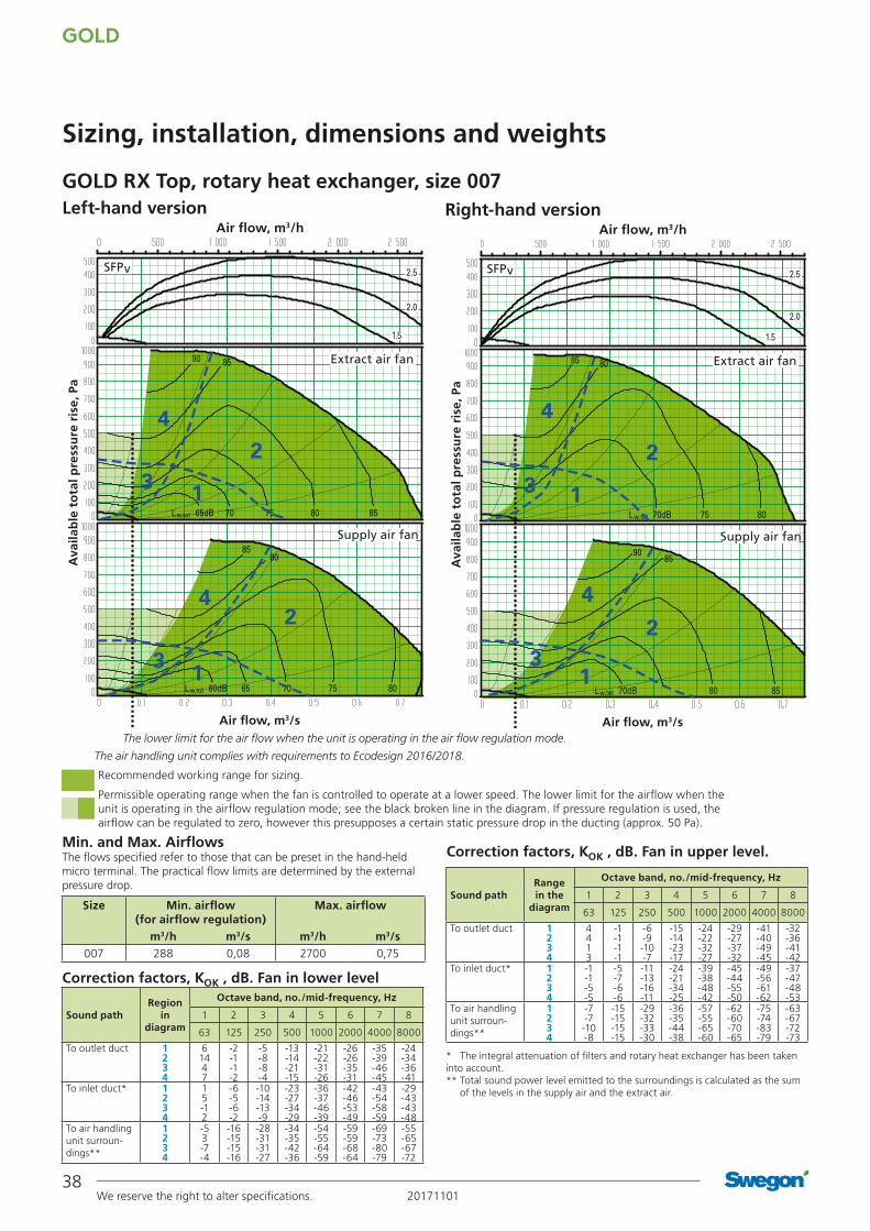
Min. and max. airflowsThe flows specified refer to those that can be preset in the hand-held micro terminal. The practical flow limits are deter-mined by the external pressure drop.
Correction factors, KOK , dB
Sizing, installation, dimensions and weights
Size Min. airflow (for airflow regulation)
Max. airflow
m3/h m3/s m3/h m3/s007 288 0,08 2700 0,75
Range in the
diagram
Octave band, no./mid-frequency, Hz
Sound path 1 2 3 4 5 6 7 8
63 125 250 500 1000 2000 4000 8000
To outlet duct 1 -1 -6 -6 -8 -7 -7 -12 -152 -1 -5 -8 -8 -7 -9 -13 -163 -1 -2 -6 -15 -14 -16 -22 -254 -2 -3 -5 -13 -13 -14 -20 -25
To inlet duct* 1 -6 -9 -12 -22 -31 -33 -38 -372 -7 -10 -17 -18 -29 -31 -37 -383 -6 -4 -14 -27 -35 -39 -44 -434 -7 -5 -12 -22 -34 -36 -42 -43
To air handling unit surroun-dings**
1 -12 -20 -29 -29 -40 -40 -46 -462 -12 -19 -31 -29 -40 -42 -47 -473 -12 -16 -29 -36 -47 -49 -56 -564 -13 -17 -28 -34 -46 -47 -54 -56
* The integral attenuation of filters and rotary heat exchanger has been taken into account. ** Total sound power level emitted to the surroundings is calcu-lated as the sum of the levels in the supply air and the extract air.
2.5
2.0
1.5
123
4
123
4
70dB 75 80 85Lw,tot
90
70dB 75 80 85Lw,tot
90 Supply air fan
Extract air fan
SFPv
Air flow, m3/s
Ava
ilab
le t
ota
l pre
ssu
re r
ise,
Pa
Air flow, m3/h
The lower limit for the air flow when the unit is operating in the air flow regulation mode.
Cap. var. 1
Cap. var. 2
Cap. var. 1
Cap. var. 2
The air handling unit complies with requirements to Ecodesign 2016/2018.
GOLD RX, rotary heat exchanger, size 007, common casing

20171101 We reserve the right to alter specifications.
GOLD
35
Sizing, installation, dimensions and weights
Power connection1-phase, 3-wire cable, 230 V -10/+15%, 50 Hz, 10 A (capacity variant 1) alt. 16 A (capacity variant 2) or 3-phase, 5-wire cable, 400 V -10/+15%, 50 Hz, 10 A
Rated data per fanMotor shaft power: 0.8 kW alt. 1.15 kW, motor control system: 1 x 230 V, 50 Hz
Clear space for inspectionA clear space of 900 mm should be provided in front of the unit and at least 200 mm should be provided above the junction hood.
Right-hand version
Left-hand version
Delivery and transport within the siteThe GOLD RX 007 is produced in one single variant. All of its components are arranged at their given physical location inside the air handling unit. The air handling unit is supplied on a wooden pallet.Prefitted base beams are obtainable as optional equipment; a separately supplied stand is available as an accessory.
Duct connection optionsA: Specify right-hand or left-hand version when ordering. If the air handling unit is supplied with all the end connection panels, the version can be changed at the building site by selecting the appropriate version in the hand-held micro terminal.B: The air handling unit can be installed up ended (does not apply to units installed outdoors). C: Specify upper fan outlet for upward air discharge when plac-ing orders (Does not apply to units installed outdoors). N.B.! Duct connection size: ø 500 mm.D: Specify whether the unit shall have an air intake from above for outdoor air or extract air when placing orders (Does not apply to units installed outdoors).
Outdoor air Supply air Extract air Exhaust air
Size A B C D F G H J L Ø Weight, kg
007 805 995 277,5 440 271 543 1085 749 1619 400 282-343
The base beams are optional. * If duct accessories are inside an insulated casing, the air handling unit is supplied without end connection panel. The AHU can also be supplied with full face end connection panel (accessory).
380 18
76 76
45 45J
16
52
305 305
ø 500 ø 400= =
Power connection
GOLD RX, rotary heat exchanger, size 007, common casing

GOLD
We reserve the right to alter specifications. 2017110136
GOLD RX, rotary heat exchanger, size 007, split version
Recommended working range for sizing.
Permissible operating range when the fan is controlled to operate at a lower speed. The lower limit for the airflow when the unit is operating in the airflow regulation mode; see the black broken line in the diagram. If pressure regulation is used, the airflow can be regulated to zero, however this presupposes a certain static pressure drop in the ducting (approx. 50 Pa).
Min. and max. airflowsThe flows specified refer to those that can be preset in the hand-held micro terminal. The practical flow limits are deter-mined by the external pressure drop.
Correction factors, KOK , dB
Sizing, installation, dimensions and weights
Size Min. airflow (for airflow regulation)
Max. airflow
m3/h m3/s m3/h m3/s007 288 0,08 2700 0,75
Range in the
diagram
Octave band, no./mid-frequency, Hz
Sound path 1 2 3 4 5 6 7 8
63 125 250 500 1000 2000 4000 8000
To outlet duct 1 -1 -6 -6 -8 -7 -7 -12 -152 -1 -5 -8 -8 -7 -9 -13 -163 -1 -2 -6 -15 -14 -16 -22 -254 -2 -3 -5 -13 -13 -14 -20 -25
To inlet duct* 1 -6 -9 -12 -22 -31 -33 -38 -372 -7 -10 -17 -18 -29 -31 -37 -383 -6 -4 -14 -27 -35 -39 -44 -434 -7 -5 -12 -22 -34 -36 -42 -43
To air handling unit surroun-dings**
1 -12 -20 -29 -29 -40 -40 -46 -462 -12 -19 -31 -29 -40 -42 -47 -473 -12 -16 -29 -36 -47 -49 -56 -564 -13 -17 -28 -34 -46 -47 -54 -56
* The integral attenuation of filters and rotary heat exchanger has been taken into account. ** Total sound power level emitted to the surroundings is calcu-lated as the sum of the levels in the supply air and the extract air.
2.5
2.0
1.5
123
4
123
4
70dB 75 80 85Lw,tot
90
70dB 75 80 85Lw,tot
90 Supply air fan
Extract air fan
SFPv
Air flow, m3/s
Ava
ilab
le t
ota
l pre
ssu
re r
ise,
Pa
Air flow, m3/h
The lower limit for the air flow when the unit is operating in the air flow regulation mode.
Cap. var. 1
Cap. var. 2
Cap. var. 1
Cap. var. 2
The air handling unit complies with requirements to Ecodesign 2016/2018.

20171101 We reserve the right to alter specifications.
GOLD
37
5252
7616380 1876 ø 500 ø 400
45 45J
K
45 45J
K
= =
305 305
GOLD RX, rotary heat exchanger, size 007, split versionDelivery and transport within the siteThe GOLD RX 007 can be supplied as one single unit, or in a number of different combinations of unit sections from the factory, see the section: Description of the Air Handling Unit/Delivery Con-figuration RX/PX/CX, sizes 004-080. Prefitted base beams as standard. The unit sections are jointed together/split by means of bolts. The electrical and control cables between the unit sections have quick-fit connectors.
Duct connection optionsA: Specify right-hand or left-hand version when ordering. If the air handling unit is supplied with all the end connection panels, the version can be changed at the building site using the hand-held terminal.B: The arrangement of the functional sections can be vertically reversed. To be specified when placing an order, see the illustration to the right.C: Specify upper fan outlet for upward air discharge when placing orders (Does not apply to units installed outdoors). N.B.! Duct connection size: ø 500 mm.D: Specify whether the unit shall have an air intake from above for outdoor air or extract air when placing orders (Does not apply to units installed outdoors).
Power connection
Size A B C D F G H J K L Ø Weight, kg
007 647.5 995 277.5 565 271 543 1085 749 440 1860 400 328-400
The unit can be divided into three sections at the building site.Dimensions: See A and D in the table above.Weight: A = 103-138 kg, D = 122-124 kg.
Division into sections for transport
A AD
Clear space for inspectionA clear space of 900 mm should be provided in front of the unit and at least 200 mm should be provided above the junction hood.
The illustration shows the connections for supply air fan, right-hand/lower level and left-hand/upper level. For supply air fan, right-hand/upper level and left-hand/lower level, the connections are mirror-inverted.* The air handling unit is supplied without end connection panel if a duct accessory housed in an insulated casing will be connected. The AHU can also be supplied with full face end connection panel (accessory).
Sizing, installation, dimensions and weights
Power connection1-phase, 3-wire, 230 V -10/+15%, 50 Hz, 10 A (capacity variant 1) or 16 A (capacity variant 2) or 3-phase, 5-wire, 400 V -10/+15%, 50 Hz, 10 A
Rated data per fanMotor shaft power: 0.8 kW alt. 1.15 kW, motor control system: 1 x 230 V, 50 Hz
Right-hand version
Left-hand version
Supply air fan, right, lower level
Supply air fan, right, upper level
Supply air fan, left, upper level
Supply air fan, left, lower level
Outdoor air Supply air Extract air Exhaust air
GOLD
We reserve the right to alter specifications. 2017110138
Recommended working range for sizing.
Permissible operating range when the fan is controlled to operate at a lower speed. The lower limit for the airflow when the unit is operating in the airflow regulation mode; see the black broken line in the diagram. If pressure regulation is used, the airflow can be regulated to zero, however this presupposes a certain static pressure drop in the ducting (approx. 50 Pa).
GOLD RX Top, rotary heat exchanger, size 007
Sizing, installation, dimensions and weights
Size Min. airflow (for airflow regulation)
Max. airflow
m3/h m3/s m3/h m3/s007 288 0,08 2700 0,75
Left-hand version Right-hand version
* The integral attenuation of filters and rotary heat exchanger has been taken into account.** Total sound power level emitted to the surroundings is calculated as the sum
of the levels in the supply air and the extract air.
Range in the
diagram
Octave band, no./mid-frequency, Hz
Sound path 1 2 3 4 5 6 7 8
63 125 250 500 1000 2000 4000 8000
To outlet duct 1 4 -1 -6 -15 -24 -29 -41 -322 4 -1 -9 -14 -22 -27 -40 -363 1 -1 -10 -23 -32 -37 -49 -414 3 -1 -7 -17 -27 -32 -45 -42
To inlet duct* 1 -1 -5 -11 -24 -39 -45 -49 -372 -1 -7 -13 -21 -38 -44 -56 -473 -5 -6 -16 -34 -48 -55 -61 -484 -5 -6 -11 -25 -42 -50 -62 -53
To air handling unit surroun-dings**
1 -7 -15 -29 -36 -57 -62 -75 -632 -7 -15 -32 -35 -55 -60 -74 -673 -10 -15 -33 -44 -65 -70 -83 -724 -8 -15 -30 -38 -60 -65 -79 -73
Region in
diagram
Octave band, no./mid-frequency, Hz
Sound path 1 2 3 4 5 6 7 8
63 125 250 500 1000 2000 4000 8000
To outlet duct 1 6 -2 -5 -13 -21 -26 -35 -242 14 -1 -8 -14 -22 -26 -39 -343 4 -1 -8 -21 -31 -35 -46 -364 7 -2 -4 -15 -26 -31 -45 -41
To inlet duct* 1 1 -6 -10 -23 -36 -42 -43 -292 5 -5 -14 -27 -37 -46 -54 -433 -1 -6 -13 -34 -46 -53 -58 -434 2 -2 -9 -29 -39 -49 -59 -48
To air handling unit surroun-dings**
1 -5 -16 -28 -34 -54 -59 -69 -552 3 -15 -31 -35 -55 -59 -73 -653 -7 -15 -31 -42 -64 -68 -80 -674 -4 -16 -27 -36 -59 -64 -79 -72
Correction factors, KOK , dB. Fan in upper level.
Correction factors, KOK , dB. Fan in lower level
Min. and Max. AirflowsThe flows specified refer to those that can be preset in the hand-held micro terminal. The practical flow limits are determined by the external pressure drop.
2.5
2.0
1.5
1
23
4
1
2
3
4
65dB 70 75 80 85Lw,tot
90 85
60dB 65 70 75 80Lw,tot
8580
Supply air fan
Extract air fan
SFPv
Air flow, m3/s
Ava
ilab
le t
ota
l pre
ssu
re r
ise,
Pa
Air flow, m3/h
2.5
2.0
1.5
70dB 75 80
8085
Lw,tot
1
2
3
4
1
23
4
Lw,tot 70dB 80 85
9085
Supply air fan
Extract air fan
SFPv
Air flow, m3/s
Ava
ilab
le t
ota
l pre
ssu
re r
ise,
Pa
Air flow, m3/h
The lower limit for the air flow when the unit is operating in the air flow regulation mode.
The air handling unit complies with requirements to Ecodesign 2016/2018.

20171101 We reserve the right to alter specifications.
GOLD
39
GOLD RX Top, rotary heat exchanger, size 007
Sizing, installation, dimensions and weights
Power connection1-phase, 3-wire cable, 230 V -10/+15%, 50 Hz, 10 A or 3-phase, 5-wire cable, 400 V -10/+15%, 50 Hz, 10 A
Rated data per fanMotor shaft power: 0.8 kW, motor control system: 1 x 230 V, 50 Hz
Clear space for inspectionA clear space of 900 mm should be provided in front of the unit and at least 200 mm should be provided above the junction hood.
Delivery and transport within the siteThe GOLD RX Top 007 unit is produced in one variant in which all the components are arranged at their given physical location inside the unit. The GOLD RX Top 007 is always supplied as one unit. The air handling unit is supplied on a wooden pallet.
Prefitted base beams are obtainable as optional equipment; a separately supplied stand is available as an accessory.
Duct connection optionsA: All the duct connections are arranged from the top of the air handling unit (the unit must not be installed outdoors).
B: The air handling unit is supplied in the right-hand version. The unit can be changed to the left-hand version at the building site by selecting the appropriate version in the hand-held micro terminal.
Outdoor air Supply air Extract air Exhaust air
Left-hand version Right-hand version
Base beams are optional.
Size A B C D F G H J L Ø Weight, kg
007 805 995 285,5 1048 280 435 1085 749 1619 400 312
45 45J5252
380 18
7616
Power connection

GOLD
We reserve the right to alter specifications. 2017110140
Recommended working range for sizing.Permissible operating range when the fan is controlled to operate at a lower speed. The lower limit for the airflow when the unit is operating in the airflow regulation mode; see the black broken line in the diagram. If pressure regulation is used, the airflow can be regulated to zero, however this presupposes a certain static pressure drop in the ducting (approx. 50 Pa).
Limit line, Ecodesign, 2018
Min. and Max. AirflowsThe flows specified refer to those that can be preset in the hand-held micro terminal. The practical flow limits are deter-mined by the external pressure drop.
Correction factors KOK , dB
Sizing, Installation, Dimensions and Weights
Size Min. airflow (on airflow regulation)
Max. airflow
m3/h m3/s m3/h m3/s008 720 0.20 3600 1.00
* The integral attenuation of filters and rotary heat exchanger has been taken into account. ** Total sound power level emitted to the surroundings is calcu-lated as the sum of the levels in the supply air and the extract air.
Range in the
diagram
Octave band, No. / mid-frequency, Hz
Sound path 1 2 3 4 5 6 7 8
63 125 250 500 1000 2000 4000 8000
To outlet duct 1 -1 -6 -6 -8 -7 -7 -12 -152 -1 -5 -8 -8 -7 -9 -13 -163 -1 -2 -6 -15 -14 -16 -22 -254 -2 -3 -5 -13 -13 -14 -20 -25
To inlet duct* 1 -6 -9 -12 -22 -31 -33 -38 -372 -7 -10 -17 -18 -29 -31 -37 -383 -6 -4 -14 -27 -35 -39 -44 -434 -7 -5 -12 -22 -34 -36 -42 -43
To air handling unit surroun-dings**
1 -12 -20 -29 -29 -40 -40 -46 -462 -12 -19 -31 -29 -40 -42 -47 -473 -12 -16 -29 -36 -47 -49 -56 -564 -13 -17 -28 -34 -46 -47 -54 -56
2.5
2.01.5
70dB 75 80 85
90
Lw,tot
70dB 75 80 85
90
Lw,tot
1
23
4
1
23
4
Supply air fan
Extract air fan
SFPv
Air flow, m3/s
Ava
ilab
le t
ota
l pre
ssu
re r
ise,
Pa
Air flow, m3/h
The lower limit for the air flow when the unit is operating in the air flow regulation mode.
Cap. var. 1
Cap. var. 2
Cap. var. 1
Cap. var. 2
The limit line for Ecodesign 2018 is calculated with capacity variant 2. The mean value for supply air and extract air must be within the limit line. The air handling unit complies with requirements to Ecodesign 2016.
GOLD RX, rotary heat exchanger, size 008, common casing

20171101 We reserve the right to alter specifications.
GOLD
41
Sizing, Installation, Dimensions and Weights
Clear Space for InspectionA clear space of 900 mm must be provided in front of the unit and at least 200 mm must be provided above the junction hood.
Right-hand version
Left-hand version
Delivery and Transport within the SiteThe GOLD RX 008 is produced in one single variant, in which all the components are arranged at their given physical locations inside the air handling unit. The air handling unit is supplied on a wooden pallet.Prefitted base beams are obtainable as optional equipment; a separately supplied stand is available as an accessory.
Duct connection optionsA: Specify right-hand or left-hand version when ordering! If the air handling unit is supplied with all the end connection panels, the version can be changed at the building site by selecting the appropriate version in the hand-held micro terminal.B: The air handling unit can be installed up ended (does not apply to units installed outdoors). C: Specify upper fan outlet for upward air discharge when plac-ing orders (Does not apply to units installed outdoors). N.B.! Duct connection size: ø 500 mm.D: Specify whether the unit shall have an air intake from above for outdoor air or extract air when placing orders (Does not apply to units installed outdoors).
Power connectionCapacity variant 1: 1-phase, 3-wire, 230 V -10/+15%, 50 Hz, 16 A or 3-phase, 5-wire, 400 V -10/+15%, 50 Hz, 10 A Capacity variant 2: 3-phase, 5-wire, 400 V -10/+15%, 50 Hz, 10 A
Rated data per fanCapacity variant 1: Motor shaft power: 1.15 kW, motor control system: 1 x 230 V, 50 Hz Capacity variant 2: Motor shaft power: 1.6 kW, motor control system: 3 x 400 V, 50 Hz
Storlek A B C D F G H J L Ø Vikt, kg
008 805 995 277,5 440 271 543 1085 749 1619 400 296-351
The base beams are optional. * If duct accessories are inside an insulated casing, the air handling unit is supplied without end connection panel. The AHU can also be supplied with full face end connection panel (accessory)..
380 18
76 76
45 45J
16
52
305 305
ø 500 ø 400= =
Elanslutning
Outdoor air Supply air Extract air Exhaust air
GOLD RX, rotary heat exchanger, size 008, common casing

GOLD
We reserve the right to alter specifications. 2017110142
GOLD RX, rotary heat exchanger, size 008, split version
Recommended working range for sizing.Permissible operating range when the fan is controlled to operate at a lower speed. The lower limit for the airflow when the unit is operating in the airflow regulation mode; see the black broken line in the diagram. If pressure regulation is used, the airflow can be regulated to zero, however this presupposes a certain static pressure drop in the ducting (approx. 50 Pa).
Limit line, Ecodesign, 2018
Min. and Max. AirflowsThe flows specified refer to those that can be preset in the hand-held micro terminal. The practical flow limits are deter-mined by the external pressure drop.
Correction factors KOK , dB
Sizing, Installation, Dimensions and Weights
Size Min. airflow (on airflow regulation)
Max. airflow
m3/h m3/s m3/h m3/s008 720 0.20 3600 1.00
* The integral attenuation of filters and rotary heat exchanger has been taken into account. ** Total sound power level emitted to the surroundings is calcu-lated as the sum of the levels in the supply air and the extract air.
Range in the
diagram
Octave band, No. / mid-frequency, Hz
Sound path 1 2 3 4 5 6 7 8
63 125 250 500 1000 2000 4000 8000
To outlet duct 1 -1 -6 -6 -8 -7 -7 -12 -152 -1 -5 -8 -8 -7 -9 -13 -163 -1 -2 -6 -15 -14 -16 -22 -254 -2 -3 -5 -13 -13 -14 -20 -25
To inlet duct* 1 -6 -9 -12 -22 -31 -33 -38 -372 -7 -10 -17 -18 -29 -31 -37 -383 -6 -4 -14 -27 -35 -39 -44 -434 -7 -5 -12 -22 -34 -36 -42 -43
To air handling unit surroun-dings**
1 -12 -20 -29 -29 -40 -40 -46 -462 -12 -19 -31 -29 -40 -42 -47 -473 -12 -16 -29 -36 -47 -49 -56 -564 -13 -17 -28 -34 -46 -47 -54 -56
2.5
2.01.5
70dB 75 80 85
90
Lw,tot
70dB 75 80 85
90
Lw,tot
1
23
4
1
23
4
Supply air fan
Extract air fan
SFPv
Air flow, m3/s
Ava
ilab
le t
ota
l pre
ssu
re r
ise,
Pa
Air flow, m3/h
The lower limit for the air flow when the unit is operating in the air flow regulation mode.
Cap. var. 1
Cap. var. 2
Cap. var. 1
Cap. var. 2
The limit line for Ecodesign 2018 is calculated with capacity variant 2. The mean value for supply air and extract air must be within the limit line. The air handling unit complies with requirements to Ecodesign 2016.

20171101 We reserve the right to alter specifications.
GOLD
43
GOLD RX, rotary heat exchanger, size 008, split versionDelivery and transport within the siteThe GOLD RX 008 can be supplied as one single unit, or in a number of different combinations of unit sections from the factory, see the section: Description of the Air Handling Unit/Delivery Configuration RX/PX/CX, sizes 004-080. Prefitted base beams as standard. The unit sections are jointed together/split by means of bolts. The electrical and control cables between the unit sections have quick-fit connectors.
Duct connection optionsA: Specify right-hand or left-hand version when ordering. If the air handling unit is supplied with all the end connection panels, the version can be changed at the building site using the hand-held terminal.B: The arrangement of the functional sections can be vertically reversed. To be specified when placing an order, see the illustra-tion to the right.C: Specify upper fan outlet for upward air discharge when plac-ing orders (Does not apply to units installed outdoors). N.B.! Duct connection size: ø 500 mm.D: Specify whether the unit shall have an air intake from above for outdoor air or extract air when placing orders (Does not apply to units installed outdoors).
Size A B C D F G H J K L Ø Weight, kg
008 647.5 995 277.5 565 271 543 1085 749 440 1860 400 342-408
The unit can be divided into three sections at the building site.Dimensions: See A and D in the table above.Weight: A = 110-142 kg, D = 122-124 kg.
Division into sections for transport
A AD
Clear space for inspectionA clear space of 900 mm should be provided in front of the unit and at least 200 mm should be provided above the junction hood.
Sizing, installation, dimensions and weights
Power connectionCapacity variant 1: 1-phase, 3-wire, 230 V -10/+15%, 50 Hz, 16 A or 3-phase, 5-wire, 400 V -10/+15%, 50 Hz, 10 A Capacity variant 2: 3-phase, 5-wire, 400 V -10/+15%, 50 Hz, 10 A
Rated data per fanCapacity variant 1: Motor shaft power: 1.15 kW, motor control system: 1 x 230 V, 50 Hz Capacity variant 2: Motor shaft power: 1.6 kW, motor control system: 3 x 400 V, 50 Hz
Right-hand version
Left-hand version
Supply air fan, right, lower level
Supply air fan, right, upper level
Supply air fan, left, upper level
Supply air fan, left, lower level
Outdoor air Supply air Extract air Exhaust air
5252
7616380 1876 ø 500 ø 400
45 45J
K
45 45J
K
= =
305 305
Power connection
The illustration shows the connections for supply air fan, right-hand/lower level and left-hand/upper level. For supply air fan, right-hand/upper level and left-hand/lower level, the connections are mirror-inverted.* The air handling unit is supplied without end connection panel if a duct accessory housed in an insulated casing will be connected. The AHU can also be supplied with full face end connection panel (accessory).
GOLD
We reserve the right to alter specifications. 2017110144
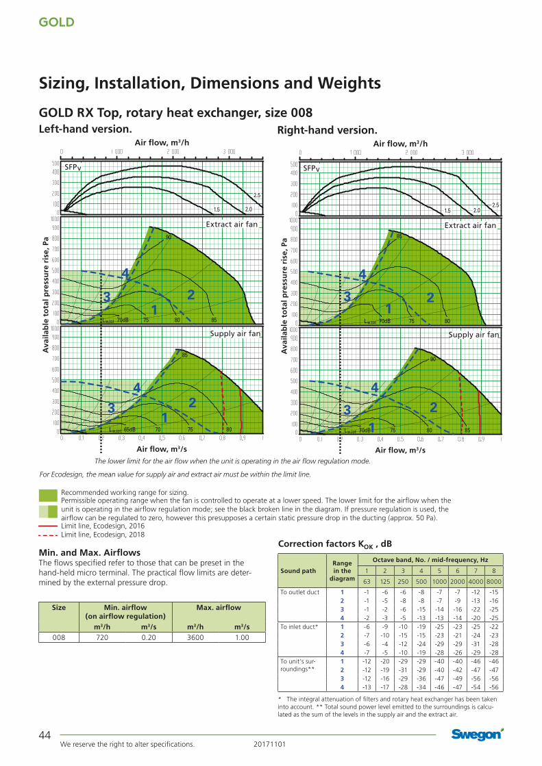
Min. and Max. AirflowsThe flows specified refer to those that can be preset in the hand-held micro terminal. The practical flow limits are deter-mined by the external pressure drop.
GOLD RX Top, rotary heat exchanger, size 008
Sizing, Installation, Dimensions and Weights
Size Min. airflow (on airflow regulation)
Max. airflow
m3/h m3/s m3/h m3/s008 720 0.20 3600 1.00
Left-hand version. Right-hand version.
Correction factors KOK , dB
* The integral attenuation of filters and rotary heat exchanger has been taken into account. ** Total sound power level emitted to the surroundings is calcu-lated as the sum of the levels in the supply air and the extract air.
Range in the
diagram
Octave band, No. / mid-frequency, Hz
Sound path 1 2 3 4 5 6 7 8
63 125 250 500 1000 2000 4000 8000
To outlet duct 1 -1 -6 -6 -8 -7 -7 -12 -152 -1 -5 -8 -8 -7 -9 -13 -163 -1 -2 -6 -15 -14 -16 -22 -254 -2 -3 -5 -13 -13 -14 -20 -25
To inlet duct* 1 -6 -9 -10 -19 -25 -23 -25 -222 -7 -10 -15 -15 -23 -21 -24 -233 -6 -4 -12 -24 -29 -29 -31 -284 -7 -5 -10 -19 -28 -26 -29 -28
To unit’s sur-roundings**
1 -12 -20 -29 -29 -40 -40 -46 -462 -12 -19 -31 -29 -40 -42 -47 -473 -12 -16 -29 -36 -47 -49 -56 -564 -13 -17 -28 -34 -46 -47 -54 -56
Recommended working range for sizing.Permissible operating range when the fan is controlled to operate at a lower speed. The lower limit for the airflow when the unit is operating in the airflow regulation mode; see the black broken line in the diagram. If pressure regulation is used, the airflow can be regulated to zero, however this presupposes a certain static pressure drop in the ducting (approx. 50 Pa).Limit line, Ecodesign, 2016 Limit line, Ecodesign, 2018
2.5
2.01.5
123
4
123
4
70dB 75 80 85Lw,tot
90
65dB 70 75 80
85
Lw,tot
Supply air fan
Extract air fan
SFPv
Air flow, m3/s
Ava
ilab
le t
ota
l pre
ssu
re r
ise,
Pa
Air flow, m3/h
The lower limit for the air flow when the unit is operating in the air flow regulation mode.
2.52.01.5
123
4
123
4
70dB 8075
85
Lw,tot
70dB 75 80 85Lw,tot
90
Supply air fan
Extract air fan
SFPv
Air flow, m3/s
Ava
ilab
le t
ota
l pre
ssu
re r
ise,
Pa
Air flow, m3/h
For Ecodesign, the mean value for supply air and extract air must be within the limit line.

20171101 We reserve the right to alter specifications.
GOLD
45
GOLD RX Top, rotary heat exchanger, size 008
Sizing, Installation, Dimensions and Weights
Power connection1-phase, 3-wire, 230 V -10/+15%, 50 Hz, 16 A or 3-phase, 5-wire, 400 V -10/+15%, 50 Hz, 10 A
Rated data per fanMotor shaft power 1.15 kW motor control system, 1 x 230 V, 50 Hz
Clear Space for InspectionA clear space of 900 mm must be provided in front of the unit and at least 200 mm must be provided above the junction hood.
Delivery and Transport within the SiteThe GOLD RX Top 008 unit is produced in one variant in which all the components are arranged at their given physical location inside the unit. The GOLD RX Top 008 is always supplied as one unit. The air handling unit is supplied on a wooden pallet.
Prefitted base beams are obtainable as optional equipment; a separately supplied stand is available as an accessory.
Duct connection optionsA: All the duct connections are arranged from the top of the air handling unit (the unit must not be installed outdoors).
B: The air handling unit is supplied in the right-hand version. The unit can be changed to the left-hand version at the building site by selecting the appropriate version in the hand-held micro terminal.
Outside air Supply air Extract air Exhaust air
Left-hand version Right-hand version
Base beams are optional.
Size A B C D F G H J L Ø Weight, kg
008 805 995 285,5 1048 280 435 1085 749 1619 400 326
45 45J5252
380 18
7616
Power connection

GOLD
We reserve the right to alter specifications. 2017110146
Recommended working range for sizing.
Permissible operating range when the fan is controlled to operate at a lower speed. The lower limit for the airflow when the unit is operating in the airflow regulation mode; see the black broken line in the diagram. If pressure regulation is used, the airflow can be regulated to zero, however this presupposes a certain static pressure drop in the ducting (approx. 50 Pa).
Min. and max. airflowsThe flows specified refer to those that can be preset in the hand-held micro terminal. The practical flow limits are deter-mined by the external pressure drop.
Correction factors, KOK , dB
GOLD RX, rotary heat exchanger, size 011
Sizing, installation, dimensions and weights
Size Min. airflow (for airflow regulation)
Max. airflow
m3/h m3/s m3/h m3/s011 720 0,20 3960 1,10
Range in the
diagram
Octave band, no./mid-frequency, Hz
Sound path 1 2 3 4 5 6 7 8
63 125 250 500 1000 2000 4000 8000
To outlet duct 1 -1 -6 -6 -8 -7 -7 -12 -152 -1 -5 -8 -8 -7 -9 -13 -163 -1 -2 -6 -15 -14 -16 -22 -254 -2 -3 -5 -13 -13 -14 -20 -25
To inlet duct* 1 -6 -9 -12 -22 -31 -33 -38 -372 -7 -10 -17 -18 -29 -31 -37 -383 -6 -4 -14 -27 -35 -39 -44 -434 -7 -5 -12 -22 -34 -36 -42 -43
To air handling unit surroun-dings**
1 -12 -20 -29 -29 -40 -40 -46 -462 -12 -19 -31 -29 -40 -42 -47 -473 -12 -16 -29 -36 -47 -49 -56 -564 -13 -17 -28 -34 -46 -47 -54 -56
* The integral attenuation of filters and rotary heat exchanger has been taken into account. ** Total sound power level emitted to the surroundings is calcu-lated as the sum of the levels in the supply air and the extract air.
2.5
2.0
1.5
7odB 75 85Lw,tot
70dB 75 80 85
90
Lw,tot
123
4
1
23
4
80
Supply air fan
Extract air fan
SFPv
Air flow, m3/s
Ava
ilab
le t
ota
l pre
ssu
re r
ise,
Pa
Air flow, m3/h
The lower limit for the air flow when the unit is operating in the air flow regulation mode.
Cap. var. 1
Cap. var. 2
Cap. var. 1
Cap. var. 2
The air handling unit complies with requirements to Ecodesign 2016/2018.

20171101 We reserve the right to alter specifications.
GOLD
47
GOLD RX, rotary heat exchanger, size 011
Sizing, installation, dimensions and weights
Power connectionCapacity variant 1: 1-phase, 3-wire cable, 230 V -10/+15%, 50 Hz, 16 A or 3-phase, 5-wire cable, 400 V -10/+15%, 50 Hz, 10 A Capacity variant 2: 3-phase, 5-wire cable, 400 V -10/+15%, 50 Hz, 10 A
Rated data per fanCapacity variant 1: Motor shaft power: 1.15 kW, motor control system: 1 x 230 V, 50 Hz Capacity variant 2: Motor shaft power: 1.6 kW, motor control system: 3 x 400 V, 50 Hz
The unit can be divided into three sections at the building site.Dimensions: See A and D in the table above.Weight: A = 135-175 kg, D = 158-160 kg.
Division into sections for transport
Clear space for inspectionA clear space of 800 mm should be provided in front of the unit and at least 200 mm should be provided above the junction hood.
45 45J
K K76
5252
16 380 18
45 45J
= = 76ø ø
350 350
Delivery and transport within the siteThe GOLD RX 011 can be supplied as one single unit, or in a num-ber of different combinations of unit sections from the factory, see the section: Description of the Air Handling Unit/Delivery Configu-ration RX/PX/CX, sizes 011-080. The unit sections are jointed together/split by means of bolts. The electrical and control cables between the unit sections have quick-fit connectors.The air handling unit/unit sections is/are delivered on wooden beams.
Duct connection optionsA: Specify right-hand or left-hand version when ordering. If the air handling unit is supplied with all the end connection panels, the version can be changed at the building site using the hand-held terminal.B: The arrangement of the functional sections can be vertically reversed. To be specified when placing an order, see the illustration to the right.C: Specify upper fan outlet for upward air discharge when placing orders (Does not apply to units installed outdoors). D: Specify whether the unit shall have an air intake from above for outdoor air or extract air when placing orders (Does not apply to units installed outdoors).
Power connection
Size A B C D F G H J K L Ø Weight, kg
011 647 1199 324 565 324 647 1295 953 551 1859 500 428-510
Right-hand version
Left-hand version
Supply air fan, right, lower level
Supply air fan, right, upper level
Supply air fan, left, upper level
Supply air fan, left, lower level
Outdoor air Supply air Extract air Exhaust air
The illustration shows the connections for supply air fan, right-hand/lower level and left-hand/upper level. For supply air fan, right-hand/upper level and left-hand/lower level, the connections are mirror-inverted.* The air handling unit is supplied without end connection panel if a duct accessory housed in an insulated casing will be connected. The AHU can also be supplied with full face end connection panel (accessory).
A AD
GOLD
We reserve the right to alter specifications. 2017110148
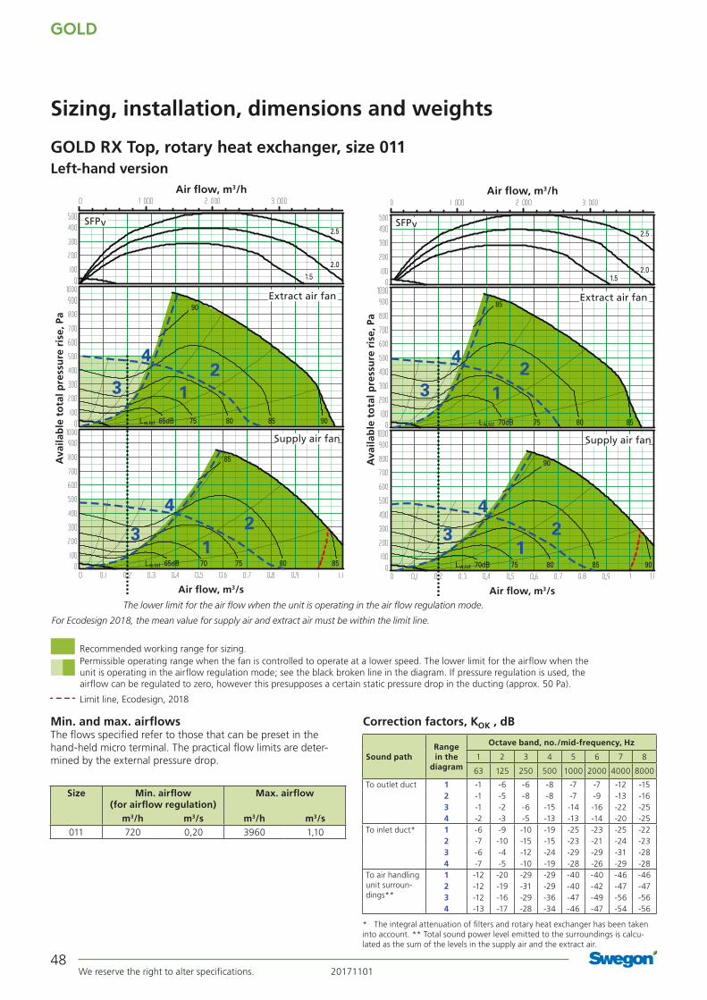
Recommended working range for sizing.Permissible operating range when the fan is controlled to operate at a lower speed. The lower limit for the airflow when the unit is operating in the airflow regulation mode; see the black broken line in the diagram. If pressure regulation is used, the airflow can be regulated to zero, however this presupposes a certain static pressure drop in the ducting (approx. 50 Pa).
Limit line, Ecodesign, 2018
Min. and max. airflowsThe flows specified refer to those that can be preset in the hand-held micro terminal. The practical flow limits are deter-mined by the external pressure drop.
GOLD RX Top, rotary heat exchanger, size 011
Sizing, installation, dimensions and weights
Size Min. airflow (for airflow regulation)
Max. airflow
m3/h m3/s m3/h m3/s011 720 0,20 3960 1,10
Left-hand version
Correction factors, KOK , dB
Range in the
diagram
Octave band, no./mid-frequency, Hz
Sound path 1 2 3 4 5 6 7 8
63 125 250 500 1000 2000 4000 8000
To outlet duct 1 -1 -6 -6 -8 -7 -7 -12 -152 -1 -5 -8 -8 -7 -9 -13 -163 -1 -2 -6 -15 -14 -16 -22 -254 -2 -3 -5 -13 -13 -14 -20 -25
To inlet duct* 1 -6 -9 -10 -19 -25 -23 -25 -222 -7 -10 -15 -15 -23 -21 -24 -233 -6 -4 -12 -24 -29 -29 -31 -284 -7 -5 -10 -19 -28 -26 -29 -28
To air handling unit surroun-dings**
1 -12 -20 -29 -29 -40 -40 -46 -462 -12 -19 -31 -29 -40 -42 -47 -473 -12 -16 -29 -36 -47 -49 -56 -564 -13 -17 -28 -34 -46 -47 -54 -56
* The integral attenuation of filters and rotary heat exchanger has been taken into account. ** Total sound power level emitted to the surroundings is calcu-lated as the sum of the levels in the supply air and the extract air.
2.5
2.0
1.5
12
3
4
12
3
4
65dB 75 80 90
90
85Lw,tot
65dB 70 75 8580Lw,tot
85
Supply air fan
Extract air fan
SFPv
Air flow, m3/s
Ava
ilab
le t
ota
l pre
ssu
re r
ise,
Pa
Air flow, m3/h
The lower limit for the air flow when the unit is operating in the air flow regulation mode.
2.5
2.01.5
12
3
4
123
4
70dB 75 80 85
85
Lw,tot
70dB 75 80 85 90Lw,tot
90
Supply air fan
Extract air fan
SFPv
Air flow, m3/s
Ava
ilab
le t
ota
l pre
ssu
re r
ise,
Pa
Air flow, m3/h
For Ecodesign 2018, the mean value for supply air and extract air must be within the limit line.

20171101 We reserve the right to alter specifications.
GOLD
49
16380 18
5252
76
45 45J
C K C
GOLD RX Top, rotary heat exchanger, size 011
Sizing, installation, dimensions and weights
Clear space for inspectionA clear space of 800 mm should be provided in front of the unit and at least 200 mm should be provided above the junction hood.
Power connection1-phase, 3-wire cable, 230 V -10/+15%, 50 Hz, 16 A or 3-phase, 5-wire cable, 400 V -10/+15%, 50 Hz, 10 A
Rated data per fanMotor shaft power: 1.15 kW, motor control system: 1 x 230 V, 50 Hz
The unit can be divided into three sections at the building site.Dimensions: See A and D in the table above.Weight: A = 160 kg, D = 159 kg.
Division into sections for transport
Delivery and transport within the siteThe GOLD RX Top 011 unit is produced in one variant in which all the components are arranged at their given physical location inside the unit. The GOLD RX Top 011 can be supplied as one single unit, or in a number of different combinations of unit sections from the factory, see the section: Description of the Air Handling Unit/Delivery Configuration RX/PX/CX, sizes 011-080. The unit sections are jointed together/split by means of bolts. The electrical and control cables between the unit sections have quick-fit connectors.The air handling unit/unit sections is/are delivered on wooden beams.
Duct connection optionsA: All the duct connections are arranged from the top of the air handling unit (the unit must not be installed outdoors). B: The air handling unit is supplied in the right-hand version. The unit can be changed to the left-hand version at the building site using the hand-held terminal.
Left-hand version Right-hand version
Outdoor air Supply air Extract air Exhaust air
Size A B C D F G H J K L Ø Weight, kg
011 647 1199 335 565 333 533 1295 953 1189 1859 500 479
Power connection
A AD

GOLD
We reserve the right to alter specifications. 2017110150
Recommended working range for sizing.Permissible operating range when the fan is controlled to operate at a lower speed. The lower limit for the airflow when the unit is operating in the airflow regulation mode; see the black broken line in the diagram. If pressure regulation is used, the airflow can be regulated to zero, however this presupposes a certain static pressure drop in the ducting (approx. 50 Pa).
Limit line, Ecodesign, 2018
Min. and Max. AirflowsThe flows specified refer to those that can be preset in the hand-held micro terminal. The practical flow limits are deter-mined by the external pressure drop.
Correction factors KOK , dB
GOLD RX, rotary heat exchanger, size 012
Sizing, Installation, Dimensions and Weights
Size Min. airflow (on airflow regulation)
Max. airflow
m3/h m3/s m3/h m3/s012 720 0.20 5040 1.40
* The integral attenuation of filters and rotary heat exchanger has been taken into account. ** Total sound power level emitted to the surroundings is calcu-lated as the sum of the levels in the supply air and the extract air.
Range in the
diagram
Octave band, No. / mid-frequency, Hz
Sound path 1 2 3 4 5 6 7 8
63 125 250 500 1000 2000 4000 8000
To outlet duct 1 -1 -6 -6 -8 -7 -7 -12 -152 -1 -5 -8 -8 -7 -9 -13 -163 -1 -2 -6 -15 -14 -16 -22 -25
To inlet duct* 1 -6 -9 -12 -22 -31 -33 -38 -372 -7 -10 -17 -18 -29 -31 -37 -383 -6 -4 -14 -27 -35 -39 -44 -43
To air handling unit surroun-dings**
1 -12 -20 -29 -29 -40 -40 -46 -462 -12 -19 -31 -29 -40 -42 -47 -473 -12 -16 -29 -36 -47 -49 -56 -56
2.5
2.0
1.5
70dB 8075 85
90
Lw,tot
123
123
70dB 80 8575Lw,tot
90
Supply air fan
Extract air fan
SFPv
Air flow, m3/s
Ava
ilab
le t
ota
l pre
ssu
re r
ise,
Pa
Air flow, m3/h
The lower limit for the air flow when the unit is operating in the air flow regulation mode.
Cap. var. 1
Cap. var. 2
Cap. var. 1
Cap. var. 2
The limit line for Ecodesign 2018 is calculated with capacity variant 2. The mean value for supply air and extract air must be within the limit line. The air handling unit complies with requirements to Ecodesign 2016.

20171101 We reserve the right to alter specifications.
GOLD
51
GOLD RX, rotary heat exchanger, size 012
Sizing, Installation, Dimensions and Weights
The unit can be divided into three sections at the building site.Dimensions: See A and D in the table above.Weight: A = 146-189 kg, D = 159 kg.
Division into sections for transport Clear space for inspectionA clear space of 800 mm should be provided in front of the unit and at least 200 mm should be provided above the junction hood.
Power connection3-phase, 5-wire, 400 V -10/+15%, 50 Hz, 10 A
Rated data per fanMotor shaft power: 1.6 kW alt. 2.4 kW, motor control system: 3 x 400 V, 50 Hz
Delivery and transport within the siteThe GOLD RX 012 can be supplied as one single unit, or in a number of different combinations of unit sections from the factory, see the section: Description of the Air Handling Unit/Delivery Configuration RX/PX/CX, sizes 011-080. The unit sections are jointed together/split by means of bolts. The electrical and control cables between the unit sections have quick-fit connectors.The air handling unit/unit sections is/are delivered on wooden beams.
Duct connection optionsA: Specify right-hand or left-hand version when ordering. If the air handling unit is supplied with all the end connection panels, the version can be changed at the building site using the hand-held terminal.B: The arrangement of the functional sections can be vertically reversed. To be specified when placing an order, see the illustra-tion to the right.C: Specify upper fan outlet for upward air discharge when plac-ing orders (Does not apply to units installed outdoors). D: Specify whether the unit shall have an air intake from above for outdoor air or extract air when placing orders (Does not apply to units installed outdoors).
Size A B C D F G H J K L Ø Weight, kg
012 647 1199 324 565 324 647 1295 953 551 1859 500 451-537
A AD
Right-hand version
Left-hand version
Supply air fan, right, lower level
Supply air fan, right, upper level
Supply air fan, left, upper level
Supply air fan, left, lower level
Outdoor air Supply air Extract air Exhaust air
45 45J
K K76
5252
16 380 18
45 45J
= = 76ø ø
350 350
Power connection
The illustration shows the connections for supply air fan, right-hand/lower level and left-hand/upper level. For supply air fan, right-hand/upper level and left-hand/lower level, the connections are mirror-inverted.* The air handling unit is supplied without end connection panel if a duct accessory housed in an insulated casing will be connected. The AHU can also be supplied with full face end connection panel (accessory).

GOLD
We reserve the right to alter specifications. 2017110152
Min. and Max. AirflowsThe flows specified refer to those that can be preset in the hand-held micro terminal. The practical flow limits are deter-mined by the external pressure drop.
GOLD RX Top, rotary heat exchanger, size 012
Sizing, Installation, Dimensions and Weights
Size Min. airflow (on airflow regulation)
Max. airflow
m3/h m3/s m3/h m3/s012 720 0,20 5040 1,40
Left-hand version. Right-hand version.
Correction factors KOK , dB
* The integral attenuation of filters and rotary heat exchanger has been taken into account. ** Total sound power level emitted to the surroundings is calcu-lated as the sum of the levels in the supply air and the extract air.
Range in the
diagram
Octave band, No. / mid-frequency, Hz
Sound path 1 2 3 4 5 6 7 8
63 125 250 500 1000 2000 4000 8000
To outlet duct 1 -1 -6 -6 -8 -7 -7 -12 -152 -1 -5 -8 -8 -7 -9 -13 -163 -1 -2 -6 -15 -14 -16 -22 -25
To inlet duct* 1 -6 -9 -10 -19 -25 -23 -25 -222 -7 -10 -15 -15 -23 -21 -24 -233 -6 -4 -12 -24 -29 -29 -31 -28
To air handling unit surroun-dings**
1 -12 -20 -29 -29 -40 -40 -46 -462 -12 -19 -31 -29 -40 -42 -47 -473 -12 -16 -29 -36 -47 -49 -56 -56
Recommended working range for sizing.Permissible operating range when the fan is controlled to operate at a lower speed. The lower limit for the airflow when the unit is operating in the airflow regulation mode; see the black broken line in the diagram. If pressure regulation is used, the airflow can be regulated to zero, however this presupposes a certain static pressure drop in the ducting (approx. 50 Pa).Limit line, Ecodesign, 2016 Limit line, Ecodesign, 2018
2.5
2.01.5
75dBLw,tot
1
23
1
23
80 85
90
65dB 70 75 80 85Lw,tot
85
Supply air fan
Extract air fan
SFPv
Air flow, m3/s
Ava
ilab
le t
ota
l pre
ssu
re r
ise,
Pa
Air flow, m3/h
The lower limit for the air flow when the unit is operating in the air flow regulation mode.
2.52.01.5
123
123
70dB 75 80
85
Lw,tot
75dB 80 85 90Lw,tot
90
Supply air fan
Extract air fan
SFPv
Air flow, m3/s
Ava
ilab
le t
ota
l pre
ssu
re r
ise,
Pa
Air flow, m3/h
For Ecodesign, the mean value for supply air and extract air must be within the limit line.

20171101 We reserve the right to alter specifications.
GOLD
53
GOLD RX Top, rotary heat exchanger, size 012
Sizing, Installation, Dimensions and Weights
Clear Space for InspectionA clear space of 800 mm must be provided in front of the unit and at least 200 mm must be provided above the junction hood.
Power connection3-phase, 5-wire, 400 V -10/+15%, 50 Hz, 10 A
Rated data per fanMotor shaft power: 1.6 kW, motor control system, 3 x 400 V, 50 Hz
The unit can be divided into three sections at the building site.Dimensions: See A and D in the table above.Weight: A = 171 kg, D = 159 kg.
Division into sections for transport
16380 18
5252
76
45 45J
C K C
Delivery and transport within the siteThe GOLD RX Top 012 unit is produced in one variant in which all the components are arranged at their given physical location inside the unit. The GOLD RX Top 012 can be supplied as one single unit, or in a number of different combinations of unit sections from the factory, see the section: Description of the Air Handling Unit/Delivery Configuration RX/PX/CX, sizes 011-080.
The unit sections are jointed together/split by means of bolts. The electrical and control cables between the unit sections have quick-fit connectors.
The air handling unit/unit sections is/are delivered on wooden beams.
Duct connection optionsA: All the duct connections are arranged from the top of the air handling unit (the unit must not be installed outdoors).
B: The air handling unit is supplied in the right-hand version. The unit can be changed to the left-hand version at the building site using the hand-held terminal.
Left-hand version Right-hand version
Outdoor air Supply air Extract air Exhaust air
Size A B C D F G H J K L Ø Weight, kg
012 647 1199 335 565 333 533 1295 953 1189 1859 500 501
Power connection
A AD
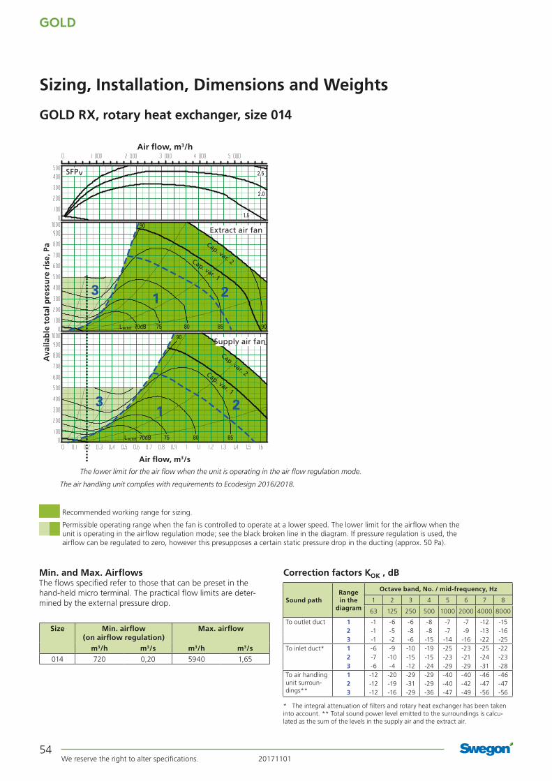
GOLD
We reserve the right to alter specifications. 2017110154
Recommended working range for sizing.
Permissible operating range when the fan is controlled to operate at a lower speed. The lower limit for the airflow when the unit is operating in the airflow regulation mode; see the black broken line in the diagram. If pressure regulation is used, the airflow can be regulated to zero, however this presupposes a certain static pressure drop in the ducting (approx. 50 Pa).
GOLD RX, rotary heat exchanger, size 014
Sizing, Installation, Dimensions and Weights
Min. and Max. AirflowsThe flows specified refer to those that can be preset in the hand-held micro terminal. The practical flow limits are deter-mined by the external pressure drop.
Correction factors KOK , dB
Size Min. airflow (on airflow regulation)
Max. airflow
m3/h m3/s m3/h m3/s014 720 0,20 5940 1,65
* The integral attenuation of filters and rotary heat exchanger has been taken into account. ** Total sound power level emitted to the surroundings is calcu-lated as the sum of the levels in the supply air and the extract air.
Range in the
diagram
Octave band, No. / mid-frequency, Hz
Sound path 1 2 3 4 5 6 7 8
63 125 250 500 1000 2000 4000 8000
To outlet duct 1 -1 -6 -6 -8 -7 -7 -12 -152 -1 -5 -8 -8 -7 -9 -13 -163 -1 -2 -6 -15 -14 -16 -22 -25
To inlet duct* 1 -6 -9 -10 -19 -25 -23 -25 -222 -7 -10 -15 -15 -23 -21 -24 -233 -6 -4 -12 -24 -29 -29 -31 -28
To air handling unit surroun-dings**
1 -12 -20 -29 -29 -40 -40 -46 -462 -12 -19 -31 -29 -40 -42 -47 -473 -12 -16 -29 -36 -47 -49 -56 -56
2.5
2.0
1.5
1 23
1 23
70dB 8075 85 90
90
Lw,tot
70dB 8075 85
90
Lw,tot
Supply air fan
Extract air fan
SFPv
Air flow, m3/s
Ava
ilab
le t
ota
l pre
ssu
re r
ise,
Pa
Air flow, m3/h
The lower limit for the air flow when the unit is operating in the air flow regulation mode.
Cap. var. 1
Cap. var. 2
Cap. var. 1
Cap. var. 2
The air handling unit complies with requirements to Ecodesign 2016/2018.
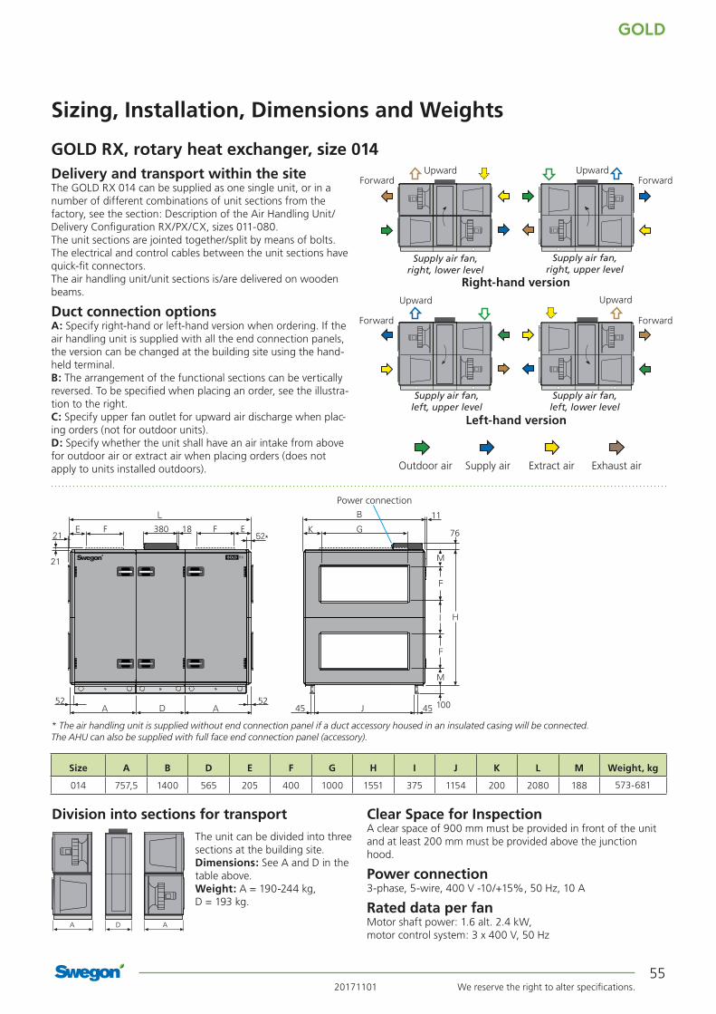
20171101 We reserve the right to alter specifications.
GOLD
55
GOLD RX, rotary heat exchanger, size 014
Sizing, Installation, Dimensions and Weights
Clear Space for InspectionA clear space of 900 mm must be provided in front of the unit and at least 200 mm must be provided above the junction hood.
Power connection3-phase, 5-wire, 400 V -10/+15%, 50 Hz, 10 A
Rated data per fanMotor shaft power: 1.6 alt. 2.4 kW, motor control system: 3 x 400 V, 50 Hz
The unit can be divided into three sections at the building site.Dimensions: See A and D in the table above.Weight: A = 190-244 kg, D = 193 kg.
Division into sections for transport
Delivery and transport within the siteThe GOLD RX 014 can be supplied as one single unit, or in a number of different combinations of unit sections from the factory, see the section: Description of the Air Handling Unit/Delivery Configuration RX/PX/CX, sizes 011-080. The unit sections are jointed together/split by means of bolts. The electrical and control cables between the unit sections have quick-fit connectors.The air handling unit/unit sections is/are delivered on wooden beams.
Duct connection optionsA: Specify right-hand or left-hand version when ordering. If the air handling unit is supplied with all the end connection panels, the version can be changed at the building site using the hand-held terminal.B: The arrangement of the functional sections can be vertically reversed. To be specified when placing an order, see the illustra-tion to the right.C: Specify upper fan outlet for upward air discharge when plac-ing orders (not for outdoor units).D: Specify whether the unit shall have an air intake from above for outdoor air or extract air when placing orders (does not apply to units installed outdoors).
Right-hand version
Left-hand version
Upward UpwardForwardForward
Upward Upward
ForwardForward
Outdoor air Supply air Extract air Exhaust air
Size A B D E F G H I J K L M Weight, kg
014 757,5 1400 565 205 400 1000 1551 375 1154 200 2080 188 573-681
EF380 18F
5252
11
M
M
76
45 45J
Power connection
* The air handling unit is supplied without end connection panel if a duct accessory housed in an insulated casing will be connected. The AHU can also be supplied with full face end connection panel (accessory).
Supply air fan, right, lower level
Supply air fan, right, upper level
Supply air fan, left, upper level
Supply air fan, left, lower level
A AD
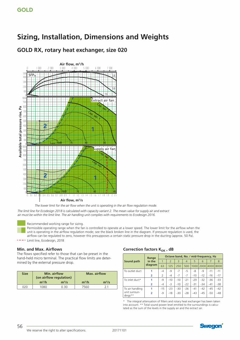
GOLD
We reserve the right to alter specifications. 2017110156
Recommended working range for sizing.Permissible operating range when the fan is controlled to operate at a lower speed. The lower limit for the airflow when the unit is operating in the airflow regulation mode; see the black broken line in the diagram. If pressure regulation is used, the airflow can be regulated to zero, however this presupposes a certain static pressure drop in the ducting (approx. 50 Pa).
Limit line, Ecodesign, 2018
GOLD RX, rotary heat exchanger, size 020
Sizing, Installation, Dimensions and Weights
Min. and Max. AirflowsThe flows specified refer to those that can be preset in the hand-held micro terminal. The practical flow limits are deter-mined by the external pressure drop.
Correction factors KOK , dB
Size Min. airflow (on airflow regulation)
Max. airflow
m3/h m3/s m3/h m3/s020 1080 0.30 7560 2.1
* The integral attenuation of filters and rotary heat exchanger has been taken into account. ** Total sound power level emitted to the surroundings is calcu-lated as the sum of the levels in the supply air and the extract air.
Range in the
diagram
Octave band, No. / mid-frequency, Hz
Sound path 1 2 3 4 5 6 7 8
63 125 250 500 1000 2000 4000 8000
To outlet duct 1 -4 -9 -7 -5 -8 -9 -11 -11
2 2 -4 -7 -7 -10 -12 -16 -17
To inlet duct* 1 -9 -10 -10 -21 -29 -32 -36 -33
2 -4 -3 -10 -22 -31 -34 -41 -38
To air handling unit surroun-dings**
1 -15 -23 -30 -26 -41 -42 -45 -42
2 -9 -18 -30 -28 -43 -45 -50 -48
2.5
2.0
1.5
70dB 75 80 85Lw,tot
70dB 75 80 85Lw,tot
1
1
2
2
Supply air fan
Extract air fan
SFPv
Air flow, m3/s
Ava
ilab
le t
ota
l pre
ssu
re r
ise,
Pa
Air flow, m3/h
The lower limit for the air flow when the unit is operating in the air flow regulation mode.
Cap. var. 1
Cap. var. 2
Cap. var. 1
Cap. var. 2
The limit line for Ecodesign 2018 is calculated with capacity variant 2. The mean value for supply air and extract air must be within the limit line. The air handling unit complies with requirements to Ecodesign 2016.

20171101 We reserve the right to alter specifications.
GOLD
57
GOLD RX, rotary heat exchanger, size 020
Sizing, Installation, Dimensions and Weights
The unit can be divided into three sections at the building site.Dimensions: See A and D in the table above.Weight: A = 200-264 kg, D = 193 kg.
Division into sections for transport Clear space for inspectionA clear space of 900 mm should be provided in front of the unit and at least 200 mm should be provided above the junction hood.
Power connection3-phase, 5-wire, 400 V -10/+15%, 50 Hz, 10 A (capacity variant 1) alt. 16 A (capacity variant 2)
Rated data per fanMotor shaft power: 2.4 kW alt. 3.4 kW, motor control system: 3 x 400 V, 50 Hz
EF380 18F
5252
11
M
M
76
45 45J
Delivery and transport within the siteThe GOLD RX 020 can be supplied as one single unit, or in a number of different combinations of unit sections from the factory, see the section: Description of the Air Handling Unit/Delivery Configuration RX/PX/CX, sizes 011-080. The unit sections are jointed together/split by means of bolts. The electrical and control cables between the unit sections have quick-fit connectors.The air handling unit/unit sections is/are delivered on wooden beams.
Duct connection optionsA: Specify right-hand or left-hand version when ordering. If the air handling unit is supplied with all the end connection panels, the version can be changed at the building site using the hand-held terminal.B: The arrangement of the functional sections can be vertically reversed. To be specified when placing an order, see the illustra-tion to the right.C: Specify upper fan outlet for upward air discharge when plac-ing orders (not for outdoor units).D: Specify whether the unit shall have an air intake from above for outdoor air or extract air when placing orders (does not apply to units installed outdoors).
Power connection
Size A B D E F G H I J K L M Weight, kg
020 757,5 1400 565 205 400 1000 1551 375 1154 200 2080 188 593-721
Right-hand version
Left-hand version
Upward UpwardForwardForward
Upward Upward
ForwardForward
Outdoor air Supply air Extract air Exhaust air
* The air handling unit is supplied without end connection panel if a duct accessory housed in an insulated casing will be connected. The AHU can also be supplied with full face end connection panel (accessory).
Supply air fan, right, lower level
Supply air fan, right, upper level
Supply air fan, left, upper level
Supply air fan, left, lower level
A AD

GOLD
We reserve the right to alter specifications. 2017110158
Recommended working range for sizing.Permissible operating range when the fan is controlled to operate at a lower speed. The lower limit for the airflow when the unit is operating in the airflow regulation mode; see the black broken line in the diagram. If pressure regulation is used, the airflow can be regulated to zero, however this presupposes a certain static pressure drop in the ducting (approx. 50 Pa).Limit line, Ecodesign, 2018
GOLD RX, rotary heat exchanger, size 025
Sizing, Installation, Dimensions and Weights
Min. and Max. AirflowsThe flows specified refer to those that can be preset in the hand-held micro terminal. The practical flow limits are deter-mined by the external pressure drop.
Correction factors KOK , dB
Size Min. airflow (on airflow regulation)
Max. airflow
m3/h m3/s m3/h m3/s025 1080 0,30 9000 2.50
* The integral attenuation of filters and rotary heat exchanger has been taken into account. ** Total sound power level emitted to the surroundings is calcu-lated as the sum of the levels in the supply air and the extract air.
Range in the
diagram
Octave band, No. / mid-frequency, Hz
Sound path 1 2 3 4 5 6 7 8
63 125 250 500 1000 2000 4000 8000
To outlet duct 1 -4 -9 -7 -5 -8 -9 -11 -11
2 2 -4 -7 -7 -10 -12 -16 -17
To inlet duct* 1 -9 -10 -10 -21 -29 -32 -36 -33
2 -4 -3 -10 -22 -31 -34 -41 -38
To air handling unit surroun-dings**
1 -15 -23 -30 -26 -41 -42 -45 -42
2 -9 -18 -30 -28 -43 -45 -50 -48
2.5
2.01.5
70dB 75 80 85
90
Lw,tot
70dB 75 80 85Lw,tot
12
12
Supply air fan
Extract air fan
SFPv
Air flow, m3/s
Ava
ilab
le t
ota
l pre
ssu
re r
ise,
Pa
Air flow, m3/h
The lower limit for the air flow when the unit is operating in the air flow regulation mode.
Cap. var. 1
Cap. var. 2
Cap. var. 1
Cap. var. 2
The limit line for Ecodesign 2018 is calculated with capacity variant 2. The mean value for supply air and extract air must be within the limit line. The air handling unit complies with requirements to Ecodesign 2016.

20171101 We reserve the right to alter specifications.
GOLD
59
GOLD RX, rotary heat exchanger, size 025
Sizing, Installation, Dimensions and Weights
Clear space for inspectionA clear space of 900 mm should be provided in front of the unit.
Power connection3-phase, 5-wire cable, 400 V -10/+15%, 50 Hz, 10 A (capacity variant 1) alt. 16 A (capacity variant 2)
Rated data per fanMotor shaft power: 2.4 kW alt. 3.4 kW, motor control system: 3 x 400 V, 50 H
The unit can be divided into three sections at the building site.Dimensions: See A and D in the table above.Weight: A = 249-333 kg, D = 248 kg.
Division into sections for transport
Size A B D E F G H I J K L M Weight, kg
025 848 1600 565 200 500 1200 1811 405 1354 200 2261 203 746-914
Delivery and transport within the siteThe GOLD RX 025 can be supplied as one single unit, or in a number of different combinations of unit sections from the factory, see the section: Description of the Air Handling Unit/Delivery Configuration RX/PX/CX, sizes 011-080. The unit sections are jointed together/split by means of bolts. The electrical and control cables between the unit sections have quick-fit connectors.The air handling unit/unit sections is/are delivered on wooden beams.
Duct connection optionsA: Specify right-hand or left-hand version when ordering. If the air handling unit is supplied with all the end connection panels, the version can be changed at the building site using the hand-held terminal.B: The arrangement of the functional sections can be vertically reversed. To be specified when placing an order, see the illustra-tion to the right.C: Specify upper fan outlet for upward air discharge when plac-ing orders (not for outdoor units).D: Specify whether the unit shall have an air intake from above for outdoor air or extract air when placing orders (does not apply to units installed outdoors).
Right-hand version
Left-hand version
Upward UpwardForwardForward
Upward Upward
ForwardForward
Outdoor air Supply air Extract air Exhaust air
Power connection
* The air handling unit is supplied without end connection panel if a duct accessory housed in an insulated casing will be connected. The AHU can also be supplied with full face end connection panel (accessory).
E
M
35
M
525245 45J
Supply air fan, right, lower level
Supply air fan, right, upper level
Supply air fan, left, upper level
Supply air fan, left, lower level
A AD

GOLD
We reserve the right to alter specifications. 2017110160
GOLD RX, rotary heat exchanger, size 030
Sizing, Installation, Dimensions and Weights
Min. and Max. AirflowsThe flows specified refer to those that can be preset in the hand-held micro terminal. The practical flow limits are deter-mined by the external pressure drop.
Correction factors KOK , dB
Size Min. airflow (on airflow regulation)
Max. airflow
m3/h m3/s m3/h m3/s030 1800 0.50 11520 3.20
* The integral attenuation of filters and rotary heat exchanger has been taken into account. ** Total sound power level emitted to the surroundings is calcu-lated as the sum of the levels in the supply air and the extract air.
Range in the
diagram
Octave band, No. / mid-frequency, Hz
Sound path 1 2 3 4 5 6 7 8
63 125 250 500 1000 2000 4000 8000
To outlet duct 1 -4 -9 -7 -5 -8 -9 -11 -11
2 2 -4 -7 -7 -10 -12 -16 -17
To inlet duct* 1 -9 -10 -10 -21 -29 -32 -36 -33
2 -4 -3 -10 -22 -31 -34 -41 -38
To air handling unit surroun-dings**
1 -15 -23 -30 -26 -41 -42 -45 -42
2 -9 -18 -30 -28 -43 -45 -50 -48
Recommended working range for sizing.Permissible operating range when the fan is controlled to operate at a lower speed. The lower limit for the airflow when the unit is operating in the airflow regulation mode; see the black broken line in the diagram. If pressure regulation is used, the airflow can be regulated to zero, however this presupposes a certain static pressure drop in the ducting (approx. 50 Pa).Limit line, Ecodesign, 2016 Limit line, Ecodesign, 2018
2.5
2.01.5
70dB 75 80 8590
Lw,tot
70dB 75 80 85
90
Lw,tot
1
2
1
2
Supply air fan
Extract air fan
SFPv
Air flow, m3/s
Ava
ilab
le t
ota
l pre
ssu
re r
ise,
Pa
Air flow, m3/h
The lower limit for the air flow when the unit is operating in the air flow regulation mode.
Cap. var. 1
Cap. var. 2
Cap. var. 1
Cap. var. 2
The limit line for Ecodesign is calculated with capacity variant 2. The mean value for supply air and extract air must be within the limit line.

20171101 We reserve the right to alter specifications.
GOLD
61
GOLD RX, rotary heat exchanger, size 030
Sizing, Installation, Dimensions and Weights
The unit can be divided into three sections at the building site.Dimensions: See A and D in the table above.Weight: A = 275-345 kg, D = 248 kg.
Division into sections for transport Clear space for inspectionA clear space of 900 mm should be provided in front of the unit.
Power connection3-phase, 5-wire, 400 V -10/+15%, 50 Hz, 20 A
Rated data per fanMotor shaft power: 4.0 kW alt. 5.0 kW, motor control system: 3 x 400 V, 50 Hz
Power connection
Size A B D E F G H I J K L M Weight, kg
030 848 1600 565 200 500 1200 1811 405 1354 200 2261 203 798-938
Delivery and transport within the siteThe GOLD RX 030 can be supplied as one single unit, or in a number of different combinations of unit sections from the factory, see the section: Description of the Air Handling Unit/Delivery Configuration RX/PX/CX, sizes 011-080. The unit sections are jointed together/split by means of bolts. The electrical and control cables between the unit sections have quick-fit connectors.The air handling unit/unit sections is/are delivered on wooden beams.
Duct connection optionsA: Specify right-hand or left-hand version when ordering. If the air handling unit is supplied with all the end connection panels, the version can be changed at the building site using the hand-held terminal.B: The arrangement of the functional sections can be vertically reversed. To be specified when placing an order, see the illustra-tion to the right.C: Specify upper fan outlet for upward air discharge when plac-ing orders (not for outdoor units).D: Specify whether the unit shall have an air intake from above for outdoor air or extract air when placing orders (does not apply to units installed outdoors).
Right-hand version
Left-hand version
Upward UpwardForwardForward
Upward Upward
ForwardForward
Outdoor air Supply air Extract air Exhaust air
* The air handling unit is supplied without end connection panel if a duct accessory housed in an insulated casing will be connected. The AHU can also be supplied with full face end connection panel (accessory).
E
M
35
M
525245 45J
Supply air fan, right, lower level
Supply air fan, right, upper level
Supply air fan, left, upper level
Supply air fan, left, lower level
A AD

GOLD
We reserve the right to alter specifications. 2017110162
GOLD RX, rotary heat exchanger, size 035
Sizing, Installation, Dimensions and Weights
Min. and max. airflowsThe flows specified refer to those that can be preset in the hand-held terminal. The practical flow limits are determined by the external pressure drop.
Correction factors, KOK , dB
Size Min. airflow (on airflow regulation)
Max. airflow
m3/h m3/s m3/h m3/s035 1800 0,50 14040 3,90
* The integral attenuation of filters and rotary heat exchanger has been taken into account.** Total sound power level emitted to the surroundings is calculated as the sum of the levels in the supply air and the extract air.
Range in the
diagram
Octave band, no./mid-frequency, Hz
Sound path 1 2 3 4 5 6 7 8
63 125 250 500 1000 2000 4000 8000
To the outlet duct
1 -4 -9 -7 -5 -8 -9 -11 -11
2 2 -4 -7 -7 -10 -12 -16 -17
To the inlet duct*
1 -9 -10 -10 -21 -29 -32 -36 -33
2 -4 -3 -10 -22 -31 -34 -41 -38
To air handling unit surround-ings**
1 -15 -23 -30 -26 -41 -42 -45 -42
2 -9 -18 -30 -28 -43 -45 -50 -48
2.5
2.0
1.5
75dB 80 85 90L w,tot
75dB 80 85 90L w,tot
12
12
Supply air fan
Extract air fan
SFPv
Air flow, m3/s
Ava
ilab
le t
ota
l pre
ssu
re r
ise,
Pa
Air flow, m3/h
The lower limit for the air flow when the unit is operating in the air flow regulation mode.
Cap. var. 1
Cap. var. 2
Cap. var. 1
Cap. var. 2
Recommended working range for sizing.Permissible operating range when the fan is controlled to operate at a lower speed. The lower limit for the air flow when the unit is operating in the air flow regulation mode; see the black broken line in the diagram. If pressure regulation is used, the air flow can be regulated to zero, however this presupposes a certain static pressure drop in the ducting (approx. 50 Pa).
The limit line for Ecodesign 2018 is calculated with capacity variant 2 and full face end connection panels (accessories). The mean value for supply air and extract air must be within the limit line. The air handling unit complies with requirements to Ecodesign 2016. Other values in diagrams are calculated for air handling units with standard end connection panels.
Limit line, Ecodesign, 2018

20171101 We reserve the right to alter specifications.
GOLD
63
GOLD RX, rotary heat exchanger, size 035
Sizing, Installation, Dimensions and Weights
M
39
M
52 5245 45J
Delivery and transport within the siteThe GOLD RX 035 can be supplied as one single unit, or in a number of different combinations of unit sections from the factory, see the section: Description of the Air Handling Unit/Delivery Configuration RX/PX/CX, sizes 011-080. The unit sections are jointed together/split by means of bolts. The electrical and control cables between the unit sections have quick-fit connectors.The air handling unit/unit sections is/are delivered on wooden beams.
Duct connection optionsA: Specify right-hand or left-hand version when ordering. If the air handling unit is supplied with all the end connection panels, the version can be changed at the building site using the hand-held terminal.B: The arrangement of the functional sections can be vertically reversed. To be specified when placing an order, see the illustra-tion to the right.C: Specify upper fan outlet for upward air discharge when plac-ing orders (not for outdoor units).D: Specify whether the unit shall have an air intake from above for outdoor air or extract air when placing orders (Does not apply to units installed outdoors).
Clear space for inspectionA clear space of 1,100 mm should be provided in front of the unit.
Power connection3-phase, 5-wire, 400 V -10/+15%, 50 Hz, 20 A
Rated data per fanMotor shaft power: 4.0 kW alt. 5.0 kW, motor control system, 3 x 400 V, 50 Hz
The unit can be divided into three sections at the building site.Dimensions: See A and D in the table above.Weight: A = 377-482 kg, D = 345 kg.
Division into sections for transport
Power connection
Size A B D E F G H I J K L M Weight, kg
035 1038.5 1990 565 245 600 1400 2159 479 1744 295 2642 240 1099-1309
Outdoor air Supply air Extract air Exhaust air
Upward Upward
ForwardForward
Upward Upward
ForwardForward
Right-hand version
Left-hand version
* The air handling unit is supplied without end connection panel if a duct accessory housed in an insulated casing will be connected. The AHU can also be supplied with full face end connection panel (accessory).
A AD
Supply air fan, right, lower level
Supply air fan, right, upper level
Supply air fan, left, upper level
Supply air fan, left, lower level

GOLD
We reserve the right to alter specifications. 2017110164
GOLD RX, rotary heat exchanger, size 040
Sizing, Installation, Dimensions and Weights
Min. and max. airflowsThe flows specified refer to those that can be preset in the hand-held terminal. The practical flow limits are determined by the external pressure drop.
Correction factors, KOK , dB
Size Min. airflow (on airflow regulation)
Max. airflow
m3/h m3/s m3/h m3/s040 2700 0,75 18000 5,00
* The integral attenuation of filters and rotary heat exchanger has been taken into account.** Total sound power level emitted to the surroundings is calculated as the sum of the levels in the supply air and the extract air.
Range in the
diagram
Octave band, no./mid-frequency, Hz
Sound path 1 2 3 4 5 6 7 8
63 125 250 500 1000 2000 4000 8000
To the outlet duct
1 -4 -9 -7 -5 -8 -9 -11 -11
2 2 -4 -7 -7 -10 -12 -16 -17
To the inlet duct*
1 -9 -10 -10 -21 -29 -32 -36 -33
2 -4 -3 -10 -22 -31 -34 -41 -38
To air handling unit surround-ings**
1 -15 -23 -30 -26 -41 -42 -45 -42
2 -9 -18 -30 -28 -43 -45 -50 -48
2.5
2.01.5
75dB 80 85 90L w,tot
75dB 80 85 90L w,tot
12
12
Supply air fan
Extract air fan
SFPv
Air flow, m3/s
Ava
ilab
le t
ota
l pre
ssu
re r
ise,
Pa
Air flow, m3/h
The lower limit for the air flow when the unit is operating in the air flow regulation mode.
Recommended working range for sizing.Permissible operating range when the fan is controlled to operate at a lower speed. The lower limit for the air flow when the unit is operating in the air flow regulation mode; see the black broken line in the diagram. If pressure regulation is used, the air flow can be regulated to zero, however this presupposes a certain static pressure drop in the ducting (approx. 50 Pa).
The limit line for Ecodesign is calculated with full face end connection panels (accessories). The mean value for supply air and extract air must be within the limit line. Other values in diagrams are calculated for air handling units with standard end connection panels.
Limit line, Ecodesign, 2016 Limit line, Ecodesign, 2018

20171101 We reserve the right to alter specifications.
GOLD
65
GOLD RX, rotary heat exchanger, size 040
Sizing, Installation, Dimensions and Weights
M
39
M
52 5245 45J
Delivery and transport within the siteThe GOLD RX 040 can be supplied as one single unit, or in a number of different combinations of unit sections from the factory, see the section: Description of the Air Handling Unit/Delivery Configuration RX/PX/CX, sizes 011-080. The unit sections are jointed together/split by means of bolts. The electrical and control cables between the unit sections have quick-fit connectors.The air handling unit/unit sections is/are delivered on wooden beams.
Duct connection optionsA: Specify right-hand or left-hand version when ordering. If the air handling unit is supplied with all the end connection panels, the version can be changed at the building site using the hand-held terminal.B: The arrangement of the functional sections can be vertically reversed. To be specified when placing an order, see the illustra-tion to the right.C: Specify upper fan outlet for upward air discharge when plac-ing orders (not for outdoor units).D: Specify whether the unit shall have an air intake from above for outdoor air or extract air when placing orders (Does not apply to units installed outdoors).
The unit can be divided into three sections at the building site.Dimensions: See A and D in the table above.Weight: A = 390-482 kg, D = 345 kg.
Division into sections for transport
Power connection
Size A B D E F G H I J K L M Weight, kg
040 1038.5 1990 565 245 600 1400 2159 479 1744 295 2642 240 1125-1335
* The air handling unit is supplied without end connection panel if a duct accessory housed in an insulated casing will be connected. The AHU can also be supplied with full face end connection panel (accessory).
A AD
Outdoor air Supply air Extract air Exhaust air
Upward Upward
ForwardForward
Upward Upward
ForwardForward
Right-hand version
Left-hand version
Supply air fan, right, lower level
Supply air fan, right, upper level
Supply air fan, left, upper level
Supply air fan, left, lower level
Clear space for inspectionA clear space of 1,100 mm should be provided in front of the unit.
Power connection3-phase, 5-wire, 400 V -10/+15%, 50 Hz, 25 A
Rated data per fanMotor shaft power: 6.5 kW, motor control system: 3 x 400 V, 50 Hz

GOLD
We reserve the right to alter specifications. 2017110166
GOLD RX, rotary heat exchanger, size 050
Sizing, Installation, Dimensions and Weights
Min. and max. airflowsThe flows specified refer to those that can be preset in the hand-held terminal. The practical flow limits are determined by the external pressure drop.
* The integral attenuation of filters and rotary heat exchanger has been taken into account.** Total sound power level emitted to the surroundings is calculated as the sum of the levels in the supply air and the extract air.
Correction factors, KOK , dB
Rangein
diagram
Octave band, no./mid-frequency, Hz
Sound path 1 2 3 4 5 6 7 8
63 125 250 500 1000 2000 4000 8000
To the outletduct
1 -4 -9 -7 -5 -8 -9 -11 -11
2 2 -4 -7 -7 -10 -12 -16 -17
To the inletduct*
1 -9 -10 -10 -21 -29 -32 -36 -33
2 -4 -3 -10 -22 -31 -34 -41 -38
To unit’s surroundings**
1 -15 -23 -30 -26 -41 -42 -45 -42
2 -9 -18 -30 -28 -43 -45 -50 -48
Recommended working range for sizing.Permissible operating range when the fan is controlled to operate at a lower speed. The lower limit for the air flow when the unit is operating in the air flow regulation mode; see the black broken line in the diagram. If pressure regulation is used, the air flow can be regulated to zero, however this presupposes a certain static pressure drop in the ducting (approx. 50 Pa).
Size Min. airflow (on airflow regulation)
Max. airflow
m3/h m3/s m3/h m3/s050 2160 0,6 18000 5,00
2.5
2.0
1.5
75dB 80 85 90L w,tot
75dB 80 85 90L w,tot
12
12
Supply air fan
Extract air fan
SFPv
Air flow, m3/s
Ava
ilab
le t
ota
l pre
ssu
re r
ise,
Pa
Air flow, m3/h
The lower limit for the air flow when the unit is operating in the air flow regulation mode.
The diagram shows air handling units including standard the end connection panels. The air handling unit complies with requirements to Ecodesign 2016/2018.

20171101 We reserve the right to alter specifications.
GOLD
67
J
39
J
52 52
78123 835 835402
782162
45
M N O
GOLD RX, rotary heat exchanger, size 050
Sizing, Installation, Dimensions and Weights
Delivery and transport within the siteThe GOLD RX 050 can be supplied as one single unit, or in a number of different combinations of unit sections from the factory, see the section: Description of the Air Handling Unit/Delivery Configuration RX/PX/CX, sizes 011-080.
The unit sections are jointed together/split by means of bolts. The electrical and control cables between the unit sections have quick-fit connectors.
The unit is supplied on 100 mm high support feet made of steel.
Duct connection optionsA: Specify right-hand or left-hand version when ordering.
B: The arrangement of the functional sections can be vertically reversed. To be specified when placing an order, see the illustra-tion to the right.
C: Specify upper fan outlet for upward air discharge when plac-ing orders (not for outdoor units).
D: Specify whether the unit shall have an air intake from above for outdoor air or extract air when placing orders (Does not apply to units installed outdoors). N.B.! Duct connection size: 2,000 x 600 mm.
The unit can be divided into three sections at the building site.Dimensions: See A and D in the table above.Weight: A = 444-563 kg, D = 414-425 kg.
Clear space for inspectionA clear space of 1,100 mm should be provided in front of the unit.
Power connection3-phase, 5-wire, 400 V -10/+15%, 50 Hz, 25 A
Rated data per fanMotor shaft power: 6.5 kW, motor control system, 3 x 400 V, 50 Hz
Division into sections for transport
Power connection
* The air handling unit is supplied without end connection panel if a duct accessory housed in an insulated casing will be con-nected. The AHU can also be supplied with full face end connection panel (accessory).
A AD
Outdoor air Supply air Extract air Exhaust air
Upward Upward
ForwardForward
Upward Upward
ForwardForward
Right-hand version
Left-hand version
Supply air fan, right, lower level
Supply air fan, right, upper level
Supply air fan, left, upper level
Supply air fan, left, lower level
Supplied on 100 mm high support feet. They can be removed or kept as they are when the unit is in place. The unit has provision for fitting the adjustable support feet.
Size A B D E F G H I J K L M N O Weight, kg
050 1038,5 2318 565 145 800 1600 2288 344 172 359 2642 600 159 2000 1302-1551

GOLD
We reserve the right to alter specifications. 2017110168
GOLD RX, rotary heat exchanger, size 060
Sizing, Installation, Dimensions and Weights
Min. and max. airflowsThe flows specified refer to those that can be preset in the hand-held terminal. The practical flow limits are determined by the external pressure drop.
Correction factors, KOK , dB
Size Min. airflow (on airflow regulation)
Max. airflow
m3/h m3/s m3/h m3/s060 3600 1,00 23400 6,50
* The integral attenuation of filters and rotary heat exchanger has been taken into account.** Total sound power level emitted to the surroundings is calculated as the sum of the levels in the supply air and the extract air.
Rangein
diagram
Octave band, no./mid-frequency, Hz
Sound path 1 2 3 4 5 6 7 8
63 125 250 500 1000 2000 4000 8000
To the outletduct
1 -4 -9 -7 -5 -8 -9 -11 -11
2 2 -4 -7 -7 -10 -12 -16 -17
To the inletduct*
1 -9 -10 -10 -21 -29 -32 -36 -33
2 -4 -3 -10 -22 -31 -34 -41 -38
To unit’s surroundings**
1 -15 -23 -30 -26 -41 -42 -45 -42
2 -9 -18 -30 -28 -43 -45 -50 -48
2.5
2.01.5
75dB 80 85 90L w,tot
12
12
75dB 80 85 90L w,tot
Supply air fan
Extract air fan
SFPv
Air flow, m3/s
Ava
ilab
le t
ota
l pre
ssu
re r
ise,
Pa
Air flow, m3/h
The lower limit for the air flow when the unit is operating in the air flow regulation mode.
Cap. var. 1
Cap. var. 2
Cap. var. 1
Cap. var. 2
Recommended working range for sizing.Permissible operating range when the fan is controlled to operate at a lower speed. The lower limit for the air flow when the unit is operating in the air flow regulation mode; see the black broken line in the diagram. If pressure regulation is used, the air flow can be regulated to zero, however this presupposes a certain static pressure drop in the ducting (approx. 50 Pa).
The limit line for Ecodesign is calculated with capacity variant 2 and full face end connection panels (accessories). The mean value for supply air and extract air must be within the limit line. Other values in diagrams are calculated for air handling units with standard end connection panels.
Limit line, Ecodesign, 2016 Limit line, Ecodesign, 2018

20171101 We reserve the right to alter specifications.
GOLD
69
J
39
J
52 52
78123 835 835402
782162
45
M N O
GOLD RX, rotary heat exchanger, size 060
Sizing, Installation, Dimensions and Weights
Delivery and transport within the siteThe GOLD RX 060 can be supplied as one single unit, or in a number of different combinations of unit sections from the factory, see the section: Description of the Air Handling Unit/Delivery Configuration RX/PX/CX, sizes 011-080.
The unit sections are jointed together/split by means of bolts. The electrical and control cables between the unit sections have quick-fit connectors.
The unit is supplied on 100 mm high support feet made of steel.
Duct connection optionsA: Specify right-hand or left-hand version when ordering.
B: The arrangement of the functional sections can be vertically reversed. To be specified when placing an order, see the illustra-tion to the right.
C: Specify upper fan outlet for upward air discharge when plac-ing orders (not for outdoor units).
D: Specify whether the unit shall have an air intake from above for outdoor air or extract air when placing orders (Does not apply to units installed outdoors). N.B.! Duct connection size: 2,000 x 600 mm.
The unit can be divided into three sections at the building site.Dimensions: See A and D in the table above.Weight: A = 511-630 kg, D = 414-425 kg.
Clear space for inspectionA clear space of 1,100 mm should be provided in front of the unit.
Power connection3-phase, 5-wire, 400 V -10/+15%, 50 Hz, 32 A (capacity variant 1) or 50 A (capacity variant 2)
Rated data per fanMotor shaft power: 2 x 4.0 kW alt. 2 x 6.5 kW, motor control system, 3 x 400 V, 50 Hz
Division into sections for transport
A AD
Power connection
Outdoor air Supply air Extract air Exhaust air
Upward Upward
ForwardForward
Upward Upward
ForwardForward
Right-hand version
Left-hand version
Supply air fan, right, lower level
Supply air fan, right, upper level
Supply air fan, left, upper level
Supply air fan, left, lower level
* The air handling unit is supplied without end connection panel if a duct accessory housed in an insulated casing will be con-nected. The AHU can also be supplied with full face end connection panel (accessory).
Supplied on 100 mm high support feet. They can be removed or kept as they are when the unit is in place. The unit has provision for fitting the adjustable support feet.
Size A B D E F G H I J K L M N O Weight, kg
060 1038,5 2318 565 145 800 1600 2288 344 172 359 2642 600 159 2000 1436-1685

GOLD
We reserve the right to alter specifications. 2017110170
GOLD RX, rotary heat exchanger, size 070
Sizing, Installation, Dimensions and Weights
Min. and max. airflowsThe flows specified refer to those that can be preset in the hand-held terminal. The practical flow limits are determined by the external pressure drop.
Correction factors, KOK , dB
Size Min. airflow (on airflow regulation)
Max. airflow
m3/h m3/s m3/h m3/s070 3600 1,00 27000 7,50
* The integral attenuation of filters and rotary heat exchanger has been taken into account.** Total sound power level emitted to the surroundings is calculated as the sum of the levels in the supply air and the extract air.
Rangein
diagram
Octave band, no./mid-frequency, Hz
Sound path 1 2 3 4 5 6 7 8
63 125 250 500 1000 2000 4000 8000
To the outletduct
1 -4 -9 -7 -5 -8 -9 -11 -11
2 2 -4 -7 -7 -10 -12 -16 -17
To the inletduct*
1 -9 -10 -10 -21 -29 -32 -36 -33
2 -4 -3 -10 -22 -31 -34 -41 -38
To unit’s surroundings**
1 -15 -23 -30 -26 -41 -42 -45 -42
2 -9 -18 -30 -28 -43 -45 -50 -48
2.5
2.0
1.5
12
12
75dB 80 85 90 95
95
L w,tot
75dB 80 85 90L w,tot
Supply air fan
Extract air fan
SFPv
Air flow, m3/s
Ava
ilab
le t
ota
l pre
ssu
re r
ise,
Pa
Air flow, m3/h
The lower limit for the air flow when the unit is operating in the air flow regulation mode.
Cap. var. 1
Cap. var. 2
Cap. var. 1
Cap. var. 2
Recommended working range for sizing.Permissible operating range when the fan is controlled to operate at a lower speed. The lower limit for the air flow when the unit is operating in the air flow regulation mode; see the black broken line in the diagram. If pressure regulation is used, the air flow can be regulated to zero, however this presupposes a certain static pressure drop in the ducting (approx. 50 Pa).
The limit line for Ecodesign 2018 is calculated with capacity variant 2 and full face end connection panels (accessories). The mean value for supply air and extract air must be within the limit line. The air handling unit complies with requirements to Ecodesign 2016. Other values in diagrams are calculated for air handling units with standard end connection panels.
Limit line, Ecodesign, 2018
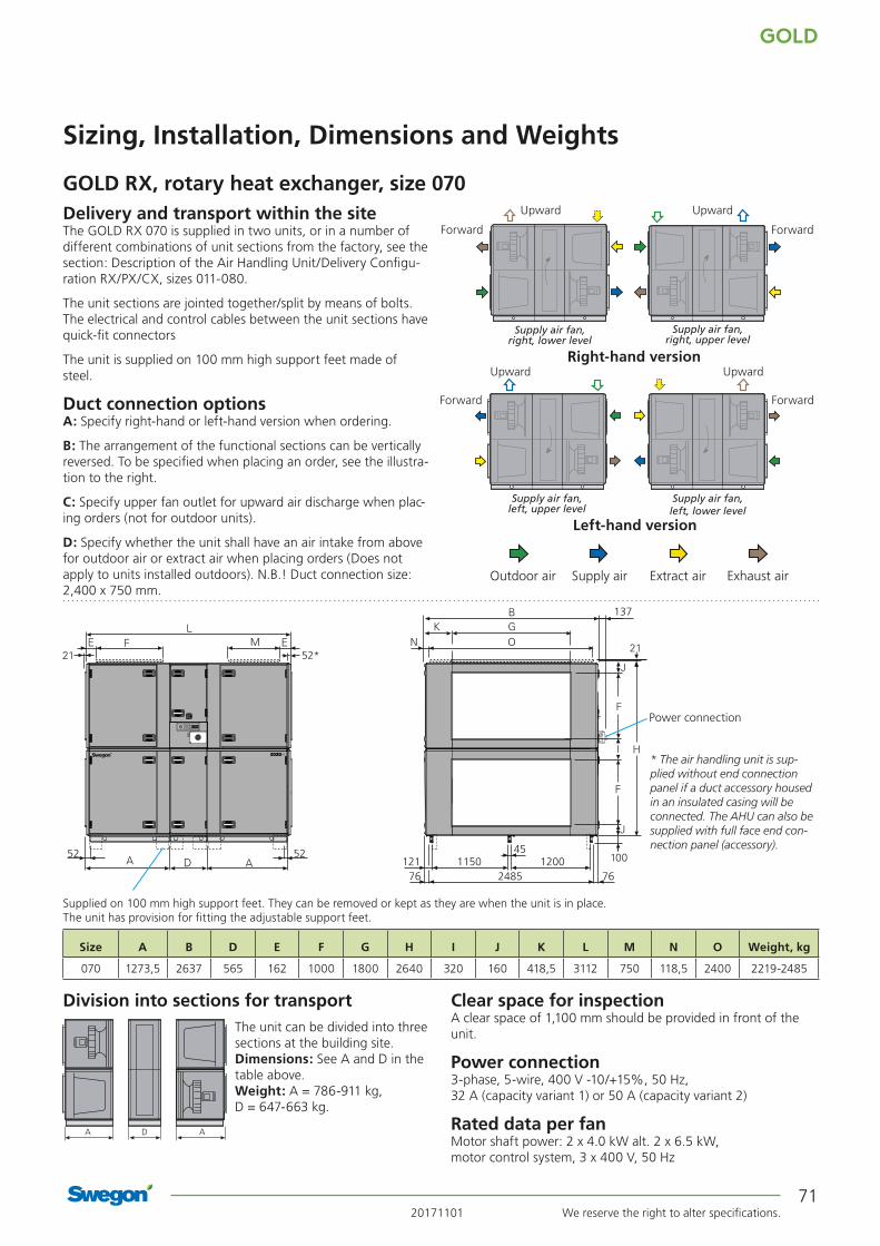
20171101 We reserve the right to alter specifications.
GOLD
71
137
52*
52 52
76121 1150 1200
45
762485
NM O
GOLD RX, rotary heat exchanger, size 070
Sizing, Installation, Dimensions and Weights
Delivery and transport within the siteThe GOLD RX 070 is supplied in two units, or in a number of different combinations of unit sections from the factory, see the section: Description of the Air Handling Unit/Delivery Configu-ration RX/PX/CX, sizes 011-080.
The unit sections are jointed together/split by means of bolts. The electrical and control cables between the unit sections have quick-fit connectors
The unit is supplied on 100 mm high support feet made of steel.
Duct connection optionsA: Specify right-hand or left-hand version when ordering.
B: The arrangement of the functional sections can be vertically reversed. To be specified when placing an order, see the illustra-tion to the right.
C: Specify upper fan outlet for upward air discharge when plac-ing orders (not for outdoor units).
D: Specify whether the unit shall have an air intake from above for outdoor air or extract air when placing orders (Does not apply to units installed outdoors). N.B.! Duct connection size: 2,400 x 750 mm.
The unit can be divided into three sections at the building site.Dimensions: See A and D in the table above.Weight: A = 786-911 kg, D = 647-663 kg.
Clear space for inspectionA clear space of 1,100 mm should be provided in front of the unit.
Power connection3-phase, 5-wire, 400 V -10/+15%, 50 Hz, 32 A (capacity variant 1) or 50 A (capacity variant 2)
Rated data per fanMotor shaft power: 2 x 4.0 kW alt. 2 x 6.5 kW, motor control system, 3 x 400 V, 50 Hz
Power connection
Division into sections for transport
A AD
Outdoor air Supply air Extract air Exhaust air
Upward Upward
ForwardForward
Upward Upward
ForwardForward
Right-hand version
Left-hand version
Supply air fan, right, lower level
Supply air fan, right, upper level
Supply air fan, left, upper level
Supply air fan, left, lower level
* The air handling unit is sup-plied without end connection panel if a duct accessory housed in an insulated casing will be connected. The AHU can also be supplied with full face end con-nection panel (accessory).
Supplied on 100 mm high support feet. They can be removed or kept as they are when the unit is in place. The unit has provision for fitting the adjustable support feet.
Size A B D E F G H I J K L M N O Weight, kg
070 1273,5 2637 565 162 1000 1800 2640 320 160 418,5 3112 750 118,5 2400 2219-2485

GOLD
We reserve the right to alter specifications. 2017110172
GOLD RX, rotary heat exchanger, size 080
Sizing, Installation, Dimensions and Weights
Min. and max. airflowsThe flows specified refer to those that can be preset in the hand-held terminal. The practical flow limits are determined by the external pressure drop.
Correction factors, KOK , dB
Size Min. airflow (on airflow regulation)
Max. airflow
m3/h m3/s m3/h m3/s080 5400 1,50 34200 9,50
* The integral attenuation of filters and rotary heat exchanger has been taken into account.** Total sound power level emitted to the surroundings is calculated as the sum of the levels in the supply air and the extract air.
Rangein
diagram
Octave band, no./mid-frequency, Hz
Sound path 1 2 3 4 5 6 7 8
63 125 250 500 1000 2000 4000 8000
To the outletduct
1 -4 -9 -7 -5 -8 -9 -11 -11
2 2 -4 -7 -7 -10 -12 -16 -17
To the inletduct*
1 -9 -10 -10 -21 -29 -32 -36 -33
2 -4 -3 -10 -22 -31 -34 -41 -38
To unit’s surroundings**
1 -15 -23 -30 -26 -41 -42 -45 -42
2 -9 -18 -30 -28 -43 -45 -50 -48
2.5
2.01.5
80dB 85 90 95L w,tot
80dB 85 90
95
L w,tot
12
12
Supply air fan
Extract air fan
SFPv
Air flow, m3/s
Ava
ilab
le t
ota
l pre
ssu
re r
ise,
Pa
Air flow, m3/h
The lower limit for the air flow when the unit is operating in the air flow regulation mode.
Cap. var. 1
Cap. var. 2
Cap. var. 1
Cap. var. 2
Recommended working range for sizing.Permissible operating range when the fan is controlled to operate at a lower speed. The lower limit for the air flow when the unit is operating in the air flow regulation mode; see the black broken line in the diagram. If pressure regulation is used, the air flow can be regulated to zero, however this presupposes a certain static pressure drop in the ducting (approx. 50 Pa).
The limit line for Ecodesign is calculated with capacity variant 2 and full face end connection panels (accessories). The mean value for supply air and extract air must be within the limit line. Other values in diagrams are calculated for air handling units with standard end connection panels.
Limit line, Ecodesign, 2016 Limit line, Ecodesign, 2018

20171101 We reserve the right to alter specifications.
GOLD
73
GOLD RX, rotary heat exchanger, size 080
Sizing, Installation, Dimensions and Weights
Delivery and transport within the siteThe GOLD RX 080 is supplied in two units, or in a number of different combinations of unit sections from the factory, see the section: Description of the Air Handling Unit/Delivery Configu-ration RX/PX/CX, sizes 011-080.
The unit sections are jointed together/split by means of bolts. The electrical and control cables between the unit sections have quick-fit connectors
The unit is supplied on 100 mm high support feet made of steel.
Duct connection optionsA: Specify right-hand or left-hand version when ordering.
B: The arrangement of the functional sections can be vertically reversed. To be specified when placing an order, see the illustra-tion to the right.
C: Specify upper fan outlet for upward air discharge when plac-ing orders (not for outdoor units).
D: Specify whether the unit shall have an air intake from above for outdoor air or extract air when placing orders (Does not apply to units installed outdoors). N.B.! Duct connection size: 2,400 x 750 mm.
The unit can be divided into three sections at the building site.Dimensions: See A and D in the table above.Weight: A = 813-1010 kg, D = 647-663 kg.
Clear space for inspectionA clear space of 1,100 mm should be provided in front of the unit.
Power connection3-phase, 5-wire, 400 V -10/+15%, 50 Hz, 50 A (capacity variant 1) or 80 A (capacity variant 2)
Rated data per fanMotor shaft power: 2 x 6.5 kW alt. 2 x 10 kW, motor control system: 3 x 400 V, 50 Hz
Power connection
Division into sections for transport
A AD
Outdoor air Supply air Extract air Exhaust air
Upward Upward
ForwardForward
Upward Upward
ForwardForward
Right-hand version
Left-hand version
Supply air fan, right, lower level
Supply air fan, right, upper level
Supply air fan, left, upper level
Supply air fan, left, lower level
* The air handling unit is sup-plied without end connection panel if a duct accessory housed in an insulated casing will be connected. The AHU can also be supplied with full face end con-nection panel (accessory).
Supplied on 100 mm high support feet. They can be removed or kept as they are when the unit is in place. The unit has provision for fitting the adjustable support feet.
137
52*
52 52
76121 1150 1200
45
762485
NM O
Size A B D E F G H I J K L M N O Weight, kg
080 1273,5 2637 565 162 1000 1800 2640 320 160 418,5 3112 750 118,5 2400 2273-2683

GOLD
We reserve the right to alter specifications. 2017110174
Sizing, Installation, Dimensions and Weights
GOLD RX, rotary heat exchanger, size 100
Min. and max. airflowsThe flows specified refer to those that can be preset in the hand-held terminal. The practical flow limits are determined by the external pressure drop.
Size Min. airflow (on airflow regulation)
Max. airflow
m3/h m3/s m3/h m3/s100 5400 1,50 39 600 11,0
Correction factors, KOK , dB
* The integral attenuation of filters and rotary heat exchanger has been taken into account.
** Total sound power level emitted to the surroundings is calculated as the sum of the levels in the supply air and the extract air.
Range in the
diagram
Octave band, no./mid-frequency, Hz
Sound path 1 2 3 4 5 6 7 8
63 125 250 500 1000 2000 4000 8000
To the outlet duct
1 -4 -9 -7 -5 -8 -9 -11 -11
2 2 -4 -7 -7 -10 -12 -16 -17
To the inlet duct*
1 -9 -10 -10 -21 -29 -32 -36 -33
2 -4 -3 -10 -22 -31 -34 -41 -38
To air handling unit surround-ings**
1 -15 -23 -30 -26 -41 -42 -45 -42
2 -9 -18 -30 -28 -43 -45 -50 -48
2.5
2.01.5
80dB 85 90 95L w,tot
80dB 85 9095
L w,tot
12
12
Supply air fan
Extract air fan
SFPv
Air flow, m3/s
Ava
ilab
le t
ota
l pre
ssu
re r
ise,
Pa
Air flow, m3/h
The lower limit for the air flow when the unit is operating in the air flow regulation mode.
Cap. var. 1
Cap. var. 2
Cap. var. 1
Cap. var. 2
Recommended working range for sizing.Permissible operating range when the fan is controlled to operate at a lower speed. The lower limit for the air flow when the unit is operating in the air flow regulation mode; see the black broken line in the diagram. If pressure regulation is used, the air flow can be regulated to zero, however this presupposes a certain static pressure drop in the ducting (approx. 50 Pa).
The limit line for Ecodesign 2018 is calculated with capacity variant 2 and full face end connection panels (accessories). The mean value for supply air and extract air must be within the limit line. The air handling unit complies with requirements to Ecodesign 2016. Other values in diagrams are calculated for air handling units with standard end connection panels.
Limit line, Ecodesign, 2018
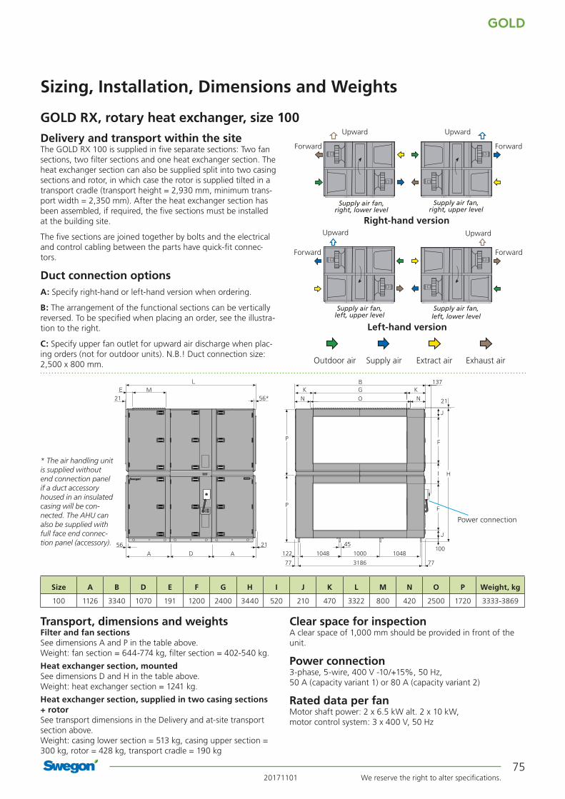
20171101 We reserve the right to alter specifications.
GOLD
75
Sizing, Installation, Dimensions and Weights
GOLD RX, rotary heat exchanger, size 100
N O N
P
P
137
56*
56
M
77 3186 77
1048 1000 1048122
45
Delivery and transport within the siteThe GOLD RX 100 is supplied in five separate sections: Two fan sections, two filter sections and one heat exchanger section. The heat exchanger section can also be supplied split into two casing sections and rotor, in which case the rotor is supplied tilted in a transport cradle (transport height = 2,930 mm, minimum trans-port width = 2,350 mm). After the heat exchanger section has been assembled, if required, the five sections must be installed at the building site.
The five sections are joined together by bolts and the electrical and control cabling between the parts have quick-fit connec-tors.
Duct connection optionsA: Specify right-hand or left-hand version when ordering.
B: The arrangement of the functional sections can be vertically reversed. To be specified when placing an order, see the illustra-tion to the right.
C: Specify upper fan outlet for upward air discharge when plac-ing orders (not for outdoor units). N.B.! Duct connection size: 2,500 x 800 mm.
Filter and fan sections See dimensions A and P in the table above. Weight: fan section = 644-774 kg, filter section = 402-540 kg.
Heat exchanger section, mountedSee dimensions D and H in the table above. Weight: heat exchanger section = 1241 kg.
Heat exchanger section, supplied in two casing sections + rotorSee transport dimensions in the Delivery and at-site transport section above. Weight: casing lower section = 513 kg, casing upper section = 300 kg, rotor = 428 kg, transport cradle = 190 kg
Clear space for inspectionA clear space of 1,000 mm should be provided in front of the unit.
Power connection3-phase, 5-wire, 400 V -10/+15%, 50 Hz, 50 A (capacity variant 1) or 80 A (capacity variant 2)
Rated data per fanMotor shaft power: 2 x 6.5 kW alt. 2 x 10 kW, motor control system: 3 x 400 V, 50 Hz
Transport, dimensions and weights
Size A B D E F G H I J K L M N O P Weight, kg
100 1126 3340 1070 191 1200 2400 3440 520 210 470 3322 800 420 2500 1720 3333-3869
Power connection
* The air handling unit is supplied without end connection panel if a duct accessory housed in an insulated casing will be con-nected. The AHU can also be supplied with full face end connec-tion panel (accessory).
Upward Upward
ForwardForward
Upward Upward
ForwardForward
Right-hand version
Left-hand version
Outdoor air Supply air Extract air Exhaust air
Supply air fan, right, lower level
Supply air fan, right, upper level
Supply air fan, left, upper level
Supply air fan, left, lower level
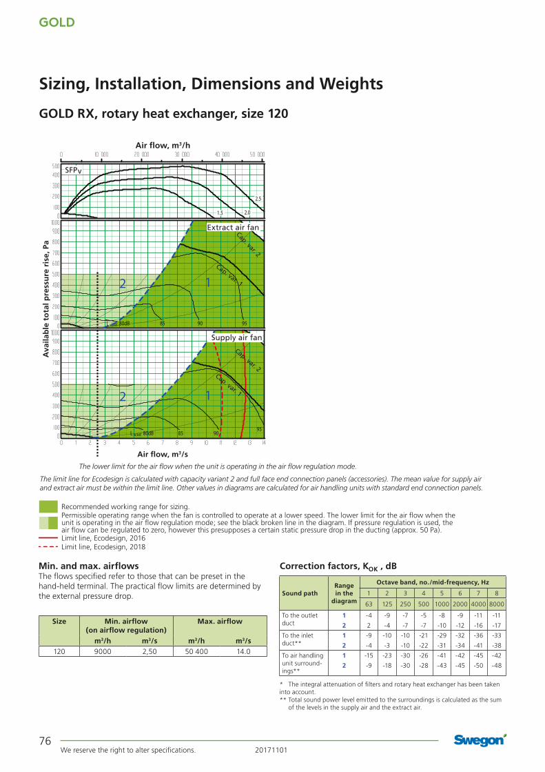
GOLD
We reserve the right to alter specifications. 2017110176
Sizing, Installation, Dimensions and Weights
GOLD RX, rotary heat exchanger, size 120
Min. and max. airflowsThe flows specified refer to those that can be preset in the hand-held terminal. The practical flow limits are determined by the external pressure drop.
Size Min. airflow (on airflow regulation)
Max. airflow
m3/h m3/s m3/h m3/s120 9000 2,50 50 400 14.0
Correction factors, KOK , dB
* The integral attenuation of filters and rotary heat exchanger has been taken into account.** Total sound power level emitted to the surroundings is calculated as the sum
of the levels in the supply air and the extract air.
Range in the
diagram
Octave band, no./mid-frequency, Hz
Sound path 1 2 3 4 5 6 7 8
63 125 250 500 1000 2000 4000 8000
To the outlet duct
1 -4 -9 -7 -5 -8 -9 -11 -11
2 2 -4 -7 -7 -10 -12 -16 -17
To the inlet duct**
1 -9 -10 -10 -21 -29 -32 -36 -33
2 -4 -3 -10 -22 -31 -34 -41 -38
To air handling unit surround-ings**
1 -15 -23 -30 -26 -41 -42 -45 -42
2 -9 -18 -30 -28 -43 -45 -50 -48
2.5
2.01.5
80dB 85 90 95
80dB 85 9095
L w,tot
12
12
L w,tot
SFPv
Air flow, m3/s
Ava
ilab
le t
ota
l pre
ssu
re r
ise,
Pa
Air flow, m3/h
The lower limit for the air flow when the unit is operating in the air flow regulation mode.
Cap. var. 1
Cap. var. 2
Cap. var. 1
Cap. var. 2
Recommended working range for sizing.Permissible operating range when the fan is controlled to operate at a lower speed. The lower limit for the air flow when the unit is operating in the air flow regulation mode; see the black broken line in the diagram. If pressure regulation is used, the air flow can be regulated to zero, however this presupposes a certain static pressure drop in the ducting (approx. 50 Pa).
The limit line for Ecodesign is calculated with capacity variant 2 and full face end connection panels (accessories). The mean value for supply air and extract air must be within the limit line. Other values in diagrams are calculated for air handling units with standard end connection panels.
Limit line, Ecodesign, 2016 Limit line, Ecodesign, 2018
Supply air fan
Extract air fan

20171101 We reserve the right to alter specifications.
GOLD
77
Sizing, Installation, Dimensions and Weights
GOLD RX, rotary heat exchanger, size 120
N O N
P
P
137
56*
56
M
77 3186 77
1048 1000 1048122
45
Delivery and transport within the siteThe GOLD RX 120 is supplied in five separate sections: Two fan sections, two filter sections and one heat exchanger section. The heat exchanger section can also be supplied split into two casing sections and rotor, in which case the rotor is supplied tilted in a transport cradle (transport height = 2,930 mm, minimum trans-port width = 2,350 mm). After the heat exchanger section has been assembled, if required, the five sections must be installed at the building site.
The five sections are joined together by bolts and the electrical and control cabling between the parts have quick-fit connec-tors.
Duct connection optionsA: Specify right-hand or left-hand version when ordering.
B: The arrangement of the functional sections can be vertically reversed. To be specified when placing an order, see the illustra-tion to the right.
C: Specify upper fan outlet for upward air discharge when plac-ing orders (not for outdoor units). N.B.! Duct connection size: 2,500 x 800 mm.
Filter and fan sections See dimensions A and P in the table above. Weight: fan section = 744-910 kg, filter section = 402-540 kg.
Heat exchanger section, mountedSee dimensions D and H in the table above. Weight: heat exchanger section = 1241 kg.
Heat exchanger section, supplied in two casing sections + rotorSee transport dimensions in the Delivery and at-site transport section above. Weight: casing lower section = 513 kg, casing upper section = 300 kg, rotor = 428 kg, transport cradle = 190 kg
Clear space for inspectionA clear space of 1,000 mm should be provided in front of the unit.
Power connection3-phase, 5-wire, 400 V -10/+15%, 50 Hz, 80 A (capacity variant 1) or 125 A (capacity variant 2)
Rated data per fanMotor shaft power: 3 x 6.5 kW alt. 3 x 10 kW, motor control system: 3 x 400 V, 50 Hz
Transport, dimensions and weights
Size A B D E F G H I J K L M N O P Weight, kg
120 1126 3340 1070 191 1200 2400 3440 520 210 470 3322 800 420 2500 1720 3533-4141
Power connection
* The air handling unit is supplied without end connection panel if a duct accessory housed in an insulated casing will be con-nected. The AHU can also be supplied with full face end connec-tion panel (accessory).
Upward Upward
ForwardForward
Upward Upward
ForwardForward
Right-hand version
Left-hand version
Outdoor air Supply air Extract air Exhaust air
Supply air fan, right, lower level
Supply air fan, right, upper level
Supply air fan, left, upper level
Supply air fan, left, lower level