SIWAREX FTC Weighing Module for Loss-in-Weight ...€¦ · SEN+ Sensor line + 36 SEN- Sensor line...
47
©Siemens AG 1 SIWAREX_FTC_L_Quick Guide _V3.1.doc; 09/2009 SIWAREX FTC Weighing Module for Loss-in-Weight Applications Set-up of SIWAREX FTC with SIWATOOL FTC_L Quick Guide For modules with order number 7MH4900-3AA01 Contents 1 HARDWARE AND SOFTWARE REQUIREMENTS.......................................................................... 3 2 COMMISSIONING .................................................................................................................................. 7 2.1 STEPS OF COMMISSIONING .................................................................................................... 7 2.2 START SIWATOOL FTC_L ................................................................................................... 8 2.3 PARAMETERIZATION AND ADJUSTMENT OF SCALES (DS3) ........................................................ 9 2.4 PARAMETERIZATION OF LOSS-IN-WEIGHT PARAMETERS 1 (DR6) ............................................ 16 2.5 PARAMETERIZATION OF INTERFACE PARAMETERS (DR7) ....................................................... 17 2.6 PARAMETERIZATION OF AUTOMATIC PARAMETERS (DR19) ..................................................... 19 2.7 DETERMINATION OF DEVICE CHARACTERISTIC CURVE (DR11) ................................................ 22 2.8 DETERMINATION OF PID PARAMETERS (DR12) ..................................................................... 27 2.9 DETERMINATION OF MATERIAL CHARACTERISTIC CURVE (DR13) ............................................ 32 2.10 FLOW RATE SET-VALUE (DR20) ............................................................................................ 36 2.11 SAVE THE CALIBRATION DATA’S INTO A FILE ........................................................................... 38 3 SWITCHING TO VOLUMETRIC OPERATION MODE UPON FLOW RATE FAULT................. 39 3.1 VOLUMETRIC MODE OF OPERATION DUE TO VIOLATION OF STABILITY CRITERIA......................... 39 3.2 CROSS-CHECK OF THE ACTUAL FLOW RATE ........................................................................... 42 4 OPTIMIZING THE SYSTEM PARAMETERS USING THE TRACE FUNCTION ........................ 44
Transcript of SIWAREX FTC Weighing Module for Loss-in-Weight ...€¦ · SEN+ Sensor line + 36 SEN- Sensor line...
©Siemens AG 1 SIWAREX_FTC_L_Quick Guide _V3.1.doc; 09/2009
SIWAREX FTC Weighing Module for Loss-in-Weight Applications Set-up of SIWAREX FTC with SIWATOOL FTC_L Quick Guide For modules with order number 7MH4900-3AA01
Contents 1 HARDWARE AND SOFTWARE REQUIREMENTS.......................................................................... 3 2 COMMISSIONING .................................................................................................................................. 7
2.1 STEPS OF COMMISSIONING .................................................................................................... 7 2.2 START SIWATOOL FTC_L ................................................................................................... 8 2.3 PARAMETERIZATION AND ADJUSTMENT OF SCALES (DS3) ........................................................ 9 2.4 PARAMETERIZATION OF LOSS-IN-WEIGHT PARAMETERS 1 (DR6) ............................................ 16 2.5 PARAMETERIZATION OF INTERFACE PARAMETERS (DR7)....................................................... 17 2.6 PARAMETERIZATION OF AUTOMATIC PARAMETERS (DR19)..................................................... 19 2.7 DETERMINATION OF DEVICE CHARACTERISTIC CURVE (DR11) ................................................ 22 2.8 DETERMINATION OF PID PARAMETERS (DR12) ..................................................................... 27 2.9 DETERMINATION OF MATERIAL CHARACTERISTIC CURVE (DR13) ............................................ 32 2.10 FLOW RATE SET-VALUE (DR20)............................................................................................ 36 2.11 SAVE THE CALIBRATION DATA’S INTO A FILE ........................................................................... 38
3 SWITCHING TO VOLUMETRIC OPERATION MODE UPON FLOW RATE FAULT................. 39 3.1 VOLUMETRIC MODE OF OPERATION DUE TO VIOLATION OF STABILITY CRITERIA......................... 39 3.2 CROSS-CHECK OF THE ACTUAL FLOW RATE ........................................................................... 42
4 OPTIMIZING THE SYSTEM PARAMETERS USING THE TRACE FUNCTION ........................ 44

©Siemens AG 2 SIWAREX_FTC_L_Quick Guide _V3.1.doc; 09/2009
Introduction SIWAREX FTC (Flexible Technology for Continuous Weighing) is a versatile and flexible weighing module for conveyor scales, loss-in-weigh scales and bulk flow meters. It can also be used to record weights and measure force. The SIWAREX FTC function module is integrated in SIMATIC S7/PCS7, and uses the features of this modern automation system, such as integral communication, diagnostics and configuration tools.
Purpose of this document for functional safety This programming manual contains all information that you will require to commission and use the device. It is aimed at persons who install the device mechanically, connect it electrically, parameterize and commission it, as well as at service and maintenance engineers.
Notes on warranty The contents of this programming manual shall not become part of or modify any prior or existing agreement, commitment or legal relationship. All obligations on the part of Siemens AG are contained in the respective sales contract, which also contains the complete and solely applicable warranty conditions. Any statements on the device versions described in the programming manual do not create new warranties or modify the existing warranty. The content reflects the technical status at the time of printing. We reserve the right to make technical changes in the course of further development.
Validation of this document This documentation is only valid in conjunction with the manual SIWAREX FTC. This manual is available on the Siemens homepage. http://support.automation.siemens.com/WW/view/en/20072536/133300

©Siemens AG 3 SIWAREX_FTC_L_Quick Guide _V3.1.doc; 09/2009
1 Hardware and software requirements The following hardware parts and software are required to integrate a scale in SIMATIC: 24V Power supply, S7-300 CPU or ET200M Station, memory card for CPU, SIWAREX FTC front connector for SIWAREX FTC, shield contact element, shield connection terminal, SIWATOOL FTC software, RS232 cable, computer with Windows XP or higher and a calibration weight bigger than 5% of the sum of the nominal value of all load cells. Requested parts: 24V PS S7-3xx PLC or ET 200M
SIWAREX FTC 7MH4900-3AA01
SIWATOOL RS232 Cable 7MH4702-8CA
Configuration Package for SIWAREX FTC Loss in weight dosing system 7MH4900-3AK02

©Siemens AG 4 SIWAREX_FTC_L_Quick Guide _V3.1.doc; 09/2009
Loss in weight, continuous dosing system Adjustment weight The operating environment shown below includes the following: PS207 2A power supply, ET200M Station or CPU3xx, SIWAREX FTC weighing module, SIWATOOL cable
SIWAREX FTC module
Load cell cable

©Siemens AG 5 SIWAREX_FTC_L_Quick Guide _V3.1.doc; 09/2009
SVPS 307 2A
6ES7 307-1BA00-
SIMATIC S7-300
SIWAREXCPU 312
6ES7 2
1 3X
SIEMEN
SIMATIS7-
S7-CPU
21 3X
EXC
WEIGHING SIWAREX
7MH 4900 -
X 12 31
S
MM
SEN
P
E
OOF
Operation via
SIEMENS Panel
MPI - Bus 0-20 mA 0 – 100
FU / Speed control
Configuration via
Siwatool

©Siemens AG 6 SIWAREX_FTC_L_Quick Guide _V3.1.doc; 09/2009
Load Cell Connection:
Connection in terminal block Signal Comment
29
IOUT+ Analogue line +
30
IOUT - Analogue line -
35
SEN+ Sensor line +
36
SEN- Sensor line –
37
SIG+ Measurement line +
38
SIG- Measurement line –
39
EXC+ Load cell supply +
40
EXC- Load cell supply –
RS232 interface24V Power supply Connection terminal of the load cells

©Siemens AG 7 SIWAREX_FTC_L_Quick Guide _V3.1.doc; 09/2009
2 Commissioning
2.1 Steps of Commissioning
A set-up of various parameters has been installed in the factory. Not all parameters have to be defined during the first commissioning. Only those parameters which have to be defined are mentioned below:
• Parameters in DR3 can only be changed when service mode is activated. • The Send button is used to transfer parameters that have been changed in Siwatool to
Siwarex. • The Send and Receive buttons refer to the entire data record and not to a single parameter.
Parameterization and adjustment of scales (DR3)
Parameterization of interface parameters (DR7)
Parameterization of loss-in-weight parameters 1 (DR6)
Parameterization of automatic parameters (DR19)
Determination of device characteristic curve (DR11)
Determination of: - PID parameters (DR12) - loss-in-weight parameters 2 (DR10) - loss in weight parameters 1 (DR6)
Determination of material characteristic curve filling columns compensation (DR13)
Definition of the flow rate set-value (DR20)

©Siemens AG 8 SIWAREX_FTC_L_Quick Guide _V3.1.doc; 09/2009
2.2 Start SIWATOOL FTC_L
On the SIWATOOL FTC_L interface, select the desired interface, which should be the COM used on your computer.
Click Online.
When the communication is established, Online turns grey.

©Siemens AG 9 SIWAREX_FTC_L_Quick Guide _V3.1.doc; 09/2009
2.3 Parameterization and adjustment of scales (DS3) Siwarex FTC has to be calibrated to show the right weight value and to calculate the actual flow value. The corresponding parameters are part of DR3.
Setting: Loss-in-weight
All other settings of this register are not relevant!
All other settings of this register are not relevant!
Weighing range: max. weighing range or mass of filling, e.g. 2.0 kg Setting the resolution range of the scales' display; e.g. 0.01 kg = 10 g

©Siemens AG 10 SIWAREX_FTC_L_Quick Guide _V3.1.doc; 09/2009
"Resolution range 1": It is the minimum change of the displayed weight. The unit is the same as the “Weight unit” selected under the "Calibration param. 3" tab. Example:
"Resolution range 1" is set to 0.05 kg, so the minimum change is 0.05 kg.
"Resolution range 1" is set to 1.0 kg, so the minimum change is 1 kg.
Note that resolution is related to weight display and is different from precision.

©Siemens AG 11 SIWAREX_FTC_L_Quick Guide _V3.1.doc; 09/2009
Weight unit and large weight unit are usually “kg and t” or “lbs and t”
Weight factor:Large weight unit= weight unit x weight factor
Enter the adjustment weight (e.g. "150.0") as “Reference 1”
Set the Characteristic value range.Indicated on sensor. Default value is 2mV/V
©Siemens AG 12 SIWAREX_FTC_L_Quick Guide _V3.1.doc; 09/2009
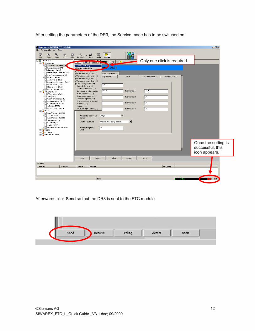
After setting the parameters of the DR3, the Service mode has to be switched on.
Afterwards click Send so that the DR3 is sent to the FTC module.
Once the setting is successful, this icon appears.
Only one click is required.
©Siemens AG 13 SIWAREX_FTC_L_Quick Guide _V3.1.doc; 09/2009
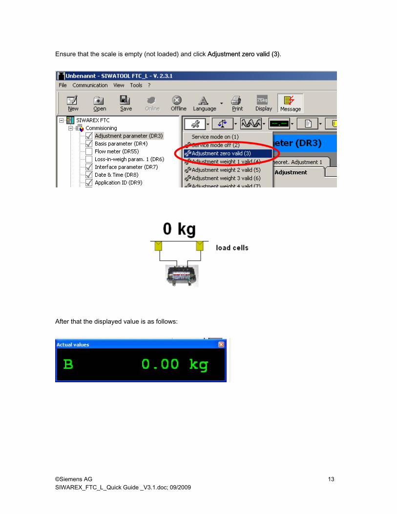
Ensure that the scale is empty (not loaded) and click Adjustment zero valid (3).
After that the displayed value is as follows:

©Siemens AG 14 SIWAREX_FTC_L_Quick Guide _V3.1.doc; 09/2009
Add the adjustment weight on the scale and then click Adjustment weight 1 valid (4).
The weight becomes the adjustment weight (e.g. 150kg) and the adjustment is complete.
If the corresponding weight is now changed it will be equal to the actual weight and exact accuracy will be achieved.

©Siemens AG 15 SIWAREX_FTC_L_Quick Guide _V3.1.doc; 09/2009
The Service mode can be switched off.

©Siemens AG 16 SIWAREX_FTC_L_Quick Guide _V3.1.doc; 09/2009
2.4 Parameterization of loss-in-weight parameters 1 (DR6)
All other settings of this register are not relevant! Click Send so that the DR6 is sent to the FTC module.
The time unit for the flow calculation normally is set to „h“ like hour. It is also possible to type in „s“ like second.
The standard filling weight has to be adapted to the actual net weight of the hopper.

©Siemens AG 17 SIWAREX_FTC_L_Quick Guide _V3.1.doc; 09/2009
2.5 Parameterization of interface parameters (DR7) This set of parameters defines various interfaces of Siwarex FTC. The analogue output e.g. for the frequency converter or the digital outputs (dosing active; filling active) has to be defined. The parameters for the analogue output have to be defined as defined in the following picture. This set up has to be done in the same way, if the set point for the frequency converter will be sent via Profibus
Parameter has to be „0.0“(= 0.0% of the flow rate)
Parameter has to be „100.0“(= 100% flow rate)
The source for the analogue output has to be selected like „PID-control output“
The current range for the frequency converter has to be selected. - „0 .. 20mA“ or - „4 .. 20mA“

©Siemens AG 18 SIWAREX_FTC_L_Quick Guide _V3.1.doc; 09/2009
This digital output can be defined as „Dosing on“
All other settings of this register are not relevant! Click Send, so that the DR7 is sent to the FTC module.
This output is set when the dosing (vol. or grav.) is active.
This digital output is set when the filling mode is active.

©Siemens AG 19 SIWAREX_FTC_L_Quick Guide _V3.1.doc; 09/2009
2.6 Parameterization of automatic parameters (DR19) This set of parameters defines autostart parameters for the execution of the automatic set-up procedure like calculation of the device characteristic curve or the determination of the PID parameters. Both parameters will be explained in a separate chapter. 1. Definition of operating points: Four operating points (control values) can be used in DR19 to define four different set points for the analogue output of the Siwarex weighing module. • Output 1 for automat. set up (0.01%) • Output 2 for automat. set up (0.01%) • Output 3 for automat. set up (0.01%) • Output 4 for automat. set up (0.01%) Note: • The values of the operating points have to increase • The values should be as close as possible to the nominal values the system will later have to operate with. • The first value has to be at least 3%. ( = 300) • The interval between the values has to be at least 1% 2. Start up time for an analogue output value: The parameter time for start-up (ms) defines the time period for a definite analogue output value during the automatic start-up phase.

©Siemens AG 20 SIWAREX_FTC_L_Quick Guide _V3.1.doc; 09/2009
In the following the parameters of data DR19 will be explained. In DR19 some default parameters are pre-defined (refer to illustration): • time for start-up (ms) = 20000 • Output 1 for automat. set up (0.01%) = 2000 • Output 2 for automat. set up (0.01%) = 6000 • Output 3 for automat. set up (0.01%) = 0 • Output 4 for automat. set up (0.01%) = 0
In case of command Automat. Startup1 (165) or Autoparameter start (164) the following control values will be set at the analogue output: 1. The first value Output 1 for autom. set up (0,01%) will be set for 20 sec: Parameter DS7: „current range
for the analogue output“
current range
Output value in %, Parameter DR19:
„Output 1 for autom. set up
(0,01%)“
Act. current (Range x
output value in %)
Start-up current for the current
range
Current at analogue output
0 .. 20 mA 20 mA 20% 4 mA 0 mA 4 mA
4 .. 20 mA 16 mA 20% 3.2 mA 4 mA 7.2 mA
Start up time
4 output values (0.01%) can be defined (increasing)

©Siemens AG 21 SIWAREX_FTC_L_Quick Guide _V3.1.doc; 09/2009
2. The second value Output 2 for automat. set up (0,01%) will be set for 20 sec: Parameter DS7: „current range
for the analogue output“
current range
Output value in %,
Parameter DR19: „Output 1 for autom. set up
(0,01%)“
Act. current (range x
output value in %)
Start-up current for the current range
Current at analogue output
0 .. 20 mA 20 mA 60% 12 mA 0 mA 12 mA
4 .. 20 mA 16 mA 60% 9.6 mA 4 mA 13.6 mA 3. The output values Output 3 for automat. set up (0,01%) and Output 4 for autom. set up (0,01%) will not be used: Both parameters are equal zero.

©Siemens AG 22 SIWAREX_FTC_L_Quick Guide _V3.1.doc; 09/2009
2.7 Determination of device characteristic curve (DR11) The characteristic curve of the dosing device defines the relation between a certain material flow and an analogue control value (current value). The general purpose of the device characteristic curve is the following: In case of switching from the gravimetric to the volumetric dosing mode the system selects those analogue control values from the characteristic curve that correspond to the flow rate set-value. Those pairs of values (max. 4) are stored in a DR 11.
Using the command Automat. Startup1 (165) the device characteristic curve will be automatically calculated. During the execution of that command the analogue control values will be set like they have been defined in DR 19 (eg.20% und 60%).
Pairs of values

©Siemens AG 23 SIWAREX_FTC_L_Quick Guide _V3.1.doc; 09/2009
In the following the device characteristic curve will be defined using command Automat. Startup1 (165):
1. The hopper should be filled to more than 90%. 2. The filling level has to be above the limit value
for refill ( start refiiling in DR 6)
Monitoring of the actual filling level

©Siemens AG 24 SIWAREX_FTC_L_Quick Guide _V3.1.doc; 09/2009
2. The screw device is filled with material.
3. The command Automat. Startup1 (165) will be executed:

©Siemens AG 25 SIWAREX_FTC_L_Quick Guide _V3.1.doc; 09/2009
4. While running the batch the bit auto startup in DR32 is actice.

©Siemens AG 26 SIWAREX_FTC_L_Quick Guide _V3.1.doc; 09/2009
After 20 sec. of startup time, the first pair of values (output value/flow rate) is added to the device characteristic curve and can be monitored by SIWATOOL after pushing the “Receive” button.

©Siemens AG 27 SIWAREX_FTC_L_Quick Guide _V3.1.doc; 09/2009
2.8 Determination of PID parameters (DR12) During the execution of command Autoparameter start (164) the following parameters will be automatically calculated: • PID-parameters (DS12) • Flow rate parameters (DS10) • Criteria for stability (DS6) Using the command Autoparameter start (164) the system defines those PID parameters running with various analogue control values defined in the device characteristic curve table DR 19 (eg.20% und 60%). The duration for each output value is corresponding to the start-up time (e.g. 20sec)

©Siemens AG 28 SIWAREX_FTC_L_Quick Guide _V3.1.doc; 09/2009
While running the batch the status flag auto startup in DR32 is actice.

©Siemens AG 29 SIWAREX_FTC_L_Quick Guide _V3.1.doc; 09/2009
After finishing the autostart procedure all these automatically calculated parameters can be monitored in DR 12, DR10 and DR6: DR6:

©Siemens AG 30 SIWAREX_FTC_L_Quick Guide _V3.1.doc; 09/2009
DR10:
DR12:
©Siemens AG 31 SIWAREX_FTC_L_Quick Guide _V3.1.doc; 09/2009
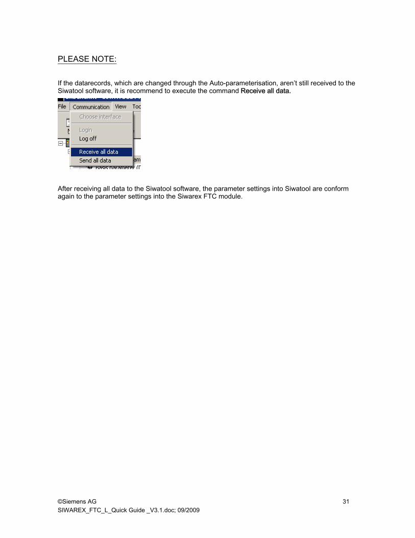
PLEASE NOTE: If the datarecords, which are changed through the Auto-parameterisation, aren’t still received to the Siwatool software, it is recommend to execute the command Receive all data.
After receiving all data to the Siwatool software, the parameter settings into Siwatool are conform again to the parameter settings into the Siwarex FTC module.
©Siemens AG 32 SIWAREX_FTC_L_Quick Guide _V3.1.doc; 09/2009
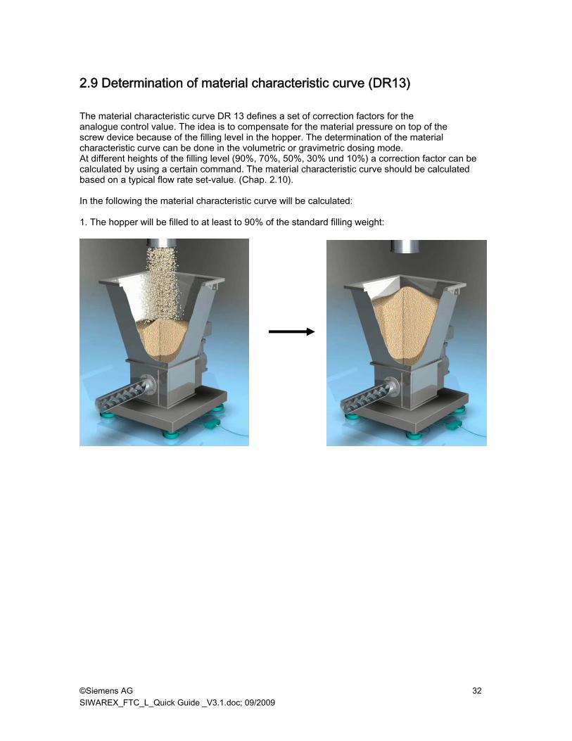
2.9 Determination of material characteristic curve (DR13) The material characteristic curve DR 13 defines a set of correction factors for the analogue control value. The idea is to compensate for the material pressure on top of the screw device because of the filling level in the hopper. The determination of the material characteristic curve can be done in the volumetric or gravimetric dosing mode. At different heights of the filling level (90%, 70%, 50%, 30% und 10%) a correction factor can be calculated by using a certain command. The material characteristic curve should be calculated based on a typical flow rate set-value. (Chap. 2.10). In the following the material characteristic curve will be calculated: 1. The hopper will be filled to at least to 90% of the standard filling weight:

©Siemens AG 33 SIWAREX_FTC_L_Quick Guide _V3.1.doc; 09/2009
2. Start dosing Dosing (auto/vol.) on (157) or Dosing (auto/grav.) on (158):
Monitoring of the hopper filling level.
Start of dosing:volumetric or gravimetric

©Siemens AG 34 SIWAREX_FTC_L_Quick Guide _V3.1.doc; 09/2009
3. Reaching the 90%-filling level the command Factor 90% (180) will be executed.
4. Reaching the 70%-filling level the command Factor 70% (179) will be executed. 5. Reaching the 50%-filling level the command Factor 50% (178) will be executed. 6. Reaching the 30%-filling level the command Factor 30% (177) will be executed. 7. Reaching the 10%-filling level the command Factor 10% (176) will be executed.
At 90%-filling level the command Factor 90% (180) will be executed.

©Siemens AG 35 SIWAREX_FTC_L_Quick Guide _V3.1.doc; 09/2009
By pushing the “Receive” button in DR 13 the calculated correction parameters can be monitored.

©Siemens AG 36 SIWAREX_FTC_L_Quick Guide _V3.1.doc; 09/2009
2.10 Flow rate set-value (DR20) In DR 20 the Flow rate set-value for the Loss-in-weight scale has to be defined. The set-value can be defined in two ways: • Quantity per time unit or: • %- value of the nominal flow rate One of the two parameters always has to be set to “0“. If the change of the flow rate set-value is more than the set-value treshold (0.01%) the system switches to the volumetric mode for a certain time period Time for volm. mode (ms). If the set-value threshold is equal „0“ there will be no change of the operating mode. DR20: Definition of the flow rate set-value: Push the button Send, to send the parameters of DR20 to the SIWAREX FTC weighing module.
Setpoint: Quantity / time unit
Setpoint as a %- value of the nominal flow rate (Nominal flow rate: Def. im DR6)

©Siemens AG 37 SIWAREX_FTC_L_Quick Guide _V3.1.doc; 09/2009
DR6: Definition of time unit and nominal flow rate:
Time unit
Nominal flow rate

©Siemens AG 38 SIWAREX_FTC_L_Quick Guide _V3.1.doc; 09/2009
2.11 Save the calibration data’s into a file Transfer all data from the SIWAREX FTC to the PC.
During the transmission from the Siwarex FTC module to the PC, the following message window appears:
Save the data as a SIWATOOL FTC File:

©Siemens AG 39 SIWAREX_FTC_L_Quick Guide _V3.1.doc; 09/2009
3 Switching to volumetric operation mode upon flow rate fault After the detection of a disturbance (like a vibration) during the gravimetric dosing the Siwarex FTC module switches to the volumetric mode. A disturbance might be detected because of:
1) Instability of weight (violation of the stability criteria) or: 2) Actual flow rate (violation of the Min/Max- Limit-value or max. change of the flow rate)
3.1 Volumetric mode of operation due to violation of stability criteria In case of violation of the stability criteria over a certain time period the Siwarex FTC module switches to the volumetric mode. The monitoring of the stability criteria is done as described below: The decreasing weight value is monitored by a „stability window“. The weight value (filtered according to parameters in DR6) is checked for a certain time period (time of stability flow in DR 6) against a maximum change of weight (Stability weight in DR 6). This means the systems monitors if the weight stays within the stability window. If the maximum weight related to the stability window is exceeded for a certain time period the actual analogue output value will be frozen and the status bit (Flow stable, DR 32) will be reset.

©Siemens AG 40 SIWAREX_FTC_L_Quick Guide _V3.1.doc; 09/2009
The following diagram illustrates the principle:
In case of violation of the stability criteria over a certain time period the status flag flow stable switches back to DR32.
Stability status in DR32

©Siemens AG 41 SIWAREX_FTC_L_Quick Guide _V3.1.doc; 09/2009
If the status bit (Flow stable) stays in status “ not true “ for a longer period than the pre-defined tolerance limit (Fault tolerance time DR10) the system will switch to the volumetric operation mode leaving the actual analogue output value unchanged. The monitoring of the stability criteria is always active. The relevant parameters for the monitoring of the stability criteria are the following ones: • Stability time flow rate DR6 • Stability weight DR6 • Fault tolerance time DR10 These parameters will automatically be calculated with the command: “Autoparameter start (164)“

©Siemens AG 42 SIWAREX_FTC_L_Quick Guide _V3.1.doc; 09/2009
3.2 Cross-check of the actual flow rate
Beside the monitoring of the stability criteria there is also the option to switch to the volumetric mode of operation by cross-checking the actual flow rate with Min/Max flow rate limits. The conditions for these cross checks can be defined by the operator in DR 12. 1. If the actual flow rate falls below the limit flow rate min. (0.01% in DR6) or exceeds the limit flow
rate max. (0.01% in DR6) related to the nominal flow rate nominal flow rate (GE/s o. GE/h in DR6), the operator can specify that the system will switch to the volumetric operation mode.
2. If the actual flow rate falls below the limit flow rate min. (0.01% in DR10) or exceeds the limit flow rate max. (0,01% in DR10) related to the actual flow rate set point defined in DR 10 flow rate set point (GE/s o. GE/h ) the operator can specify that the system will switch to the volumetric operation mode.
3. If the flow rate change exceeds the Max. flow rate change +/- (0,01%/s in DR10) related to the nominal flow rate nominal flow rate (GE/s o. GE/h in DR6), the operator can specify that the system will switch to the volumetric operation mode.
The limits are related to the nominal flow rate or to the actual set value. They define a tolerance band around the nominal flow rate or the actual set value. • Flow rate min. (0,01%) related the nominal flow rate • Flow rate max. (0,01%) related the nominal flow rate • Flow rate min. (0,01%) related to the actual set point • Flow rate max. (0,01%) related to the actual set point • Max. change of flow rate +/- (0,01%/s)
Example: flow rate set value = 200,0
Flow limit max. (0,01%) of the set value = 1000 Flow limit min. (0,01%) ort he set value = 2000
Tolerance band flow rate max. = 10% from set value
Tolerance band flow rate min. = 20% from set value
Flow rate max. = 220,0
Flow rate min. = 160,0
Set value = 200,0

©Siemens AG 43 SIWAREX_FTC_L_Quick Guide _V3.1.doc; 09/2009
Switching to the volumetric operation mode can be done in two ways: 1. Freezing the actual analogue output (continuing operation with the actual analogue
output value). 2. Picking up the analogue output value related the flow rate set point derived from a
combination of the device - and the material characteristic curve table.
Switching condition related to the nominal flow rate DR6
Switching condition related to the actual flow rate set point in DR10
Switching condition related to the nominal flow rate in DR10

©Siemens AG 44 SIWAREX_FTC_L_Quick Guide _V3.1.doc; 09/2009
4 Optimizing the system parameters using the trace function To optimize the parameter set up of the loss-in-weight system, the operator can use the trace–function. In a pre-defined recording cycle this recording function stores the most important weighing and process data inside the internal RAM of the Siwarex module. In a second step, these data can be exported to Excel. Preparation of a trace: Using the Button “Receive” data (DR 7) will be read from the weighing module.
The following parameters can be changed: - Memory for trace - Trace function recording cycle
Using the button “Send” the data can be sent to the Siwarex module:
Value 10ms x n meanse.g.: 10ms x 10 = 100ms each 100ms a Trace-ID will be recorded.

©Siemens AG 45 SIWAREX_FTC_L_Quick Guide _V3.1.doc; 09/2009
Running the trace: The Command Start recording/trace (70) starts the recording of data . The command End recording/trace (71) stops the recording of data.
Export of data to Excel (or *.csv-file) : Pushing the button “Receive” in DR123 the recorded Trace-ID-numbers can be read. In the following example there are traces with the ID-numbers „0“ to „548“:
Starts the recording
Stops the recording
oldest Trace-ID-number
youngest Trace-ID-number

©Siemens AG 46 SIWAREX_FTC_L_Quick Guide _V3.1.doc; 09/2009
Via DR121 the recorded Trace-data can be exported into Excel (or in a *.csv-file). Before pushing the Buttons “Export to Excel” (or “Export to File”) the Trace-ID numbers have to be entered (in the example „0“ and „548“. Afterwards the button “Start export” has to be pushed.
Then all data can be analyzed with Excel:
Starting point for the Trace
Final Trace-ID-number
1.
2.
3.

©Siemens AG 47 SIWAREX_FTC_L_Quick Guide _V3.1.doc; 09/2009
If you have any issues or suggestions regarding the related products or documents, please feel free to contact:
Technical support for SIWAREX:
Siemens AG Industry Automation (IA) Sensors and Communication Process Instrumentation D-76181 Karlsruhe Germany Tel: +49 721 595 2811 Fax: +49 721 595 2901 E-mail: [email protected] Website: www.semens.com/siwarex
Copyright Statement
All rights reserved by Siemens AG This document is subject to change without notice. Under no circumstances shall the content of this document be construed as an express or implied promise, guarantee (for any method, product or equipment) or implication by or from Siemens AG. Partial or full replication or translation of this document without written permission from Siemens AG is illegal.