
SISTEME DE PROCESARE A IMAGINII SIMATIC MV.pdf
17
Siemens FS 10 · 2009 3 3 / / 2 2 I I n n t t r r o o d d u u c c t t i i o o n n 3 3 / / 4 4 S S I I M M A A T T I I C C M M V V 2 2 2 2 0 0 3 3 / / 7 7 S S I I M M A A T T I I C C M M V V 2 2 3 3 0 0 3 3 / / 1 1 0 0 S S I I M M A A T T I I C C V V S S 1 1 2 2 0 0 3 3 / / 1 1 3 3 L L e e n n s s e e s s V V i i s s i i o o n n S S e e n n s s o o r r s s © Siemens AG 2008
-
Upload
serdar-aksoy -
Category
Documents
-
view
220 -
download
0
Transcript of SISTEME DE PROCESARE A IMAGINII SIMATIC MV.pdf

8/21/2019 SISTEME DE PROCESARE A IMAGINII SIMATIC MV.pdf
http://slidepdf.com/reader/full/sisteme-de-procesare-a-imaginii-simatic-mvpdf 1/16
Siemens FS 10 · 2009
33/ / 22 I Innttrroodduuccttiioonn
3
3
/
/
4
4
S
S
I
I
M
M
A
A
T
T
I
I
C
C
M
M
V
V
2
2
2
2
0
0
3
3
/
/
7
7
S
S
I
I
M
M
A
A
T
T
I
I
C
C
M
M
V
V
2
2
3
3
0
0
3
3
/
/
1
1
0
0
S
S
I
I
M
M
A
A
T
T
I
I
C
C
V
V
S
S
1
1
2
2
0
0
3
3
/
/
1
1
3
3
L
L
e
e
n
n
s
s
e
e
s
s
VViissiio
onn SSeennssoorrss
© Siemens AG 2008
8/21/2019 SISTEME DE PROCESARE A IMAGINII SIMATIC MV.pdf
http://slidepdf.com/reader/full/sisteme-de-procesare-a-imaginii-simatic-mvpdf 2/16
Vision SensorsIntroduction
3 / 2 Siemens FS 10 · 2009
3
V
V
i
i
s
s
i
i
o
o
n
n
s
s
e
e
n
n
s
s
o
o
r
r
s
s
–
–
S
S
i
i
m
m
p
p
l
l
e
e
a
a
n
n
d
d
i
i
n
n
t
t
e
e
l
l
l
l
i
i
g
g
e
e
n
n
t
t
SS II MM AATT II CC MM VV 22 22 00 cc oo ll oo rr mm aa rr kk ss ee nn ss oo rr
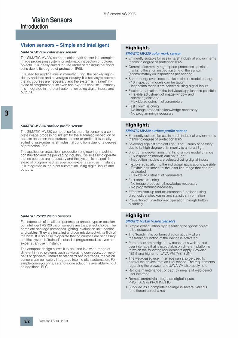
The SIMATIC MV220 compact color mark sensor is a completeimage processing system for automatic inspection of coloredobjects. It is ideally suited for use under harsh industrial condi-tions due to its degree of protection IP65.
It is used for applications in manufacturing, the packaging in-dustry and food and beverages industry. It is so easy to operatethat no courses are necessary and the system is "trained" in-stead of programmed, so even non-experts can use it instantly.It is integrated in the plant automation using digital inputs andoutputs.
S
S
I
I
M
M
A
A
T
T
I
I
C
C
M
M
V
V
2
2
3
3
0
0
s
s
u
u
r
r
f
f
a
a
c
c
e
e
p
p
r
r
o
o
f
f
i
i
l
l
e
e
s
s
e
e
n
n
s
s
o
o
r
r
The SIMATIC MV230 compact surface profile sensor is a com-plete image processing system for the automatic inspection ofobjects based on their surface contour or profile. It is ideallysuited for use under harsh industrial conditions due to its degreeof protection IP65.
The application areas lie in production engineering, machineconstruction and the packaging industry. It is so easy to operatethat no courses are necessary and the system is "trained" in-stead of programmed, so even non-experts can use it instantly.It is integrated in the plant automation using digital inputs andoutputs.
SS II MM AATT II CC VV SS 1122 00 VV ii ss ii oo nn SS ee nn ss oo rr ss
For inspection of small components for shape, type or position,our intelligent VS120 vision sensors are the perfect choice. Thecomplete package comprises lighting, evaluation unit, sensorand cables. They are installed and commissioned with a flick of
the wrist. It is so easy to operate that no courses are necessaryand the system is "trained" instead of programmed, so even non-experts can use it instantly.
The compact design allows it to be used in a wide range ofdifferent infeed systems such as vibrating conveyors, conveyorbelts or grippers. Thanks to standardized interfaces, the visionsensors can be flexibly integrated into the plant automation. Forsimple conveyor units, a stand-alone solution is available withoutan additional PLC.
HighlightsSS II MM AATT II CC MM VV 22 22 00 cc oo ll oo rr mm aa rr kk ss ee nn ss oo rr
• Eminently suitable for use in harsh industrial environmentsthanks to degree of protection IP65
• Control of extremely high-speed processes possiblethanks to the short inspection time of the sensor(approximately 30 inspections per second)
• Short changeover times thanks to simple model change- 16 inspection models can be taught- Inspection models are selected using digital inputs
• Flexible adaptation to the individual applications possible- Flexible adjustment of image window and
operating distance- Flexible adjustment of parameters
• Fast commissioning- No image processing knowledge necessary- No programming necessary
Highlights
S
S
I
I
M
M
A
A
T
T
I
I
C
C
M
M
V
V
2
2
3
3
0
0
s
s
u
u
r
r
f
f
a
a
c
c
e
e
p
p
r
r
o
o
f
f
i
i
l
l
e
e
s
s
e
e
n
n
s
s
o
o
r
r
• Eminently suitable for use in harsh industrial environmentsthanks to degree of protection IP65
• Shielding against ambient light is not usually necessarydue to its high degree of immunity to ambient light
• Short changeover times thanks to simple model change- 16 inspection models can be taught- Inspection models are selected using digital inputs
• Flexible adaptation to the individual applications possible- Flexible adjustment of the laser line range that can be
evaluated- Flexible adjustment of parameters
• Fast commissioning- No image processing knowledge necessary- No programming necessary
• Effective start-up and maintenance functions usingdiagnostics, checksums and statistical information
• Prevention of unauthorized operation through buttondisabling
HighlightsSS II MM AATT II CC VV SS 1122 00 VV ii ss ii oo nn SS ee nn ss oo rr ss
• Simple configuration by presenting the "good" objectto be detected.
• The "teach-in" is performed automatically whenthe training function of the device is activated.
• Parameters are assigned by means of a web-baseduser interface that is executable on different platformsto which the following requirements apply: Browser(IE5.5 and higher) or JAVA-VM (MS, SUN).
• The web-based user interface can also be used tocontrol the device from an HMI device. The requirementsregarding the browser and JAVA VM also apply here.
• Remote maintenance concept by means of web-baseduser interface.
• Remote control via integrated digital inputs,PROFIBUS or PROFINET IO.
• Supplied as a complete package in several variantsfor different object sizes
© Siemens AG 2008

8/21/2019 SISTEME DE PROCESARE A IMAGINII SIMATIC MV.pdf
http://slidepdf.com/reader/full/sisteme-de-procesare-a-imaginii-simatic-mvpdf 3/16
Vision SensorsIntroduction
3 / 3Siemens FS 10 · 2009
3
AApppplliiccaattiioonn
T
T
e
e
c
c
h
h
n
n
i
i
c
c
a
a
l
l
s
s
p
p
e
e
c
c
i
i
f
f
i
i
c
c
a
a
t
t
i
i
o
o
n
n
s
s
FFi
ieel
ldds
s
o
of
f
a
appppl
li
ic
ca
at
ti
io
onn
f
f o
or
r
t
thhee
vvi
is
si
io
onn
s
seenns
so
or
rs
s
O
Obbj
jeec
ct
t
i
inns
sp
peec
ct
ti
io
onn
wwi
it
thh
S
SIIMMAATTIICC
MMVV22220
0
Inspection task Color inspection tasks in manufacturing and assembly systems
Applications Manufacturing, packaging industry and food and beverages industry
Type of parts to be inspected e.g. completeness of colored parts, blister packs, cups, bott les, labels and covers
O
O
b
b
j
je
e
c
c
t
t
i
in
n
s
s
p
p
e
e
c
c
t
t
i
io
o
n
n
w
w
i
it
t
h
h
S
S
I
I
M
M
A
A
T
T
I
I
C
C
M
M
V
V
2
2
3
3
0
0
Inspection task Inspection of surface contours and profiles in production engineering and assembly
Applications Production engineering, the packaging industry and machine construction
Type of parts to be inspected Inspection, parts recognition and position checking of partsbased on their geometric surface contour or profile
OObbj jeecctt iinnssppeeccttiioonn wwiitthh SSIIMMAATTIICC VVSS112200
Inspection task Correctness, lack of damage and position of a part or pattern;position of the part with x/y coordinate and angle of rotation in degrees
Applications Conveyor belts, workholder carousels, gripper units, production machines
Type of parts to be inspected e.g. screws, bolts, molded parts, pharmaceutical products, confectionery, logos, patterns ...
T
T
y
y
p
p
e
e
M
M
V
V
2
2
2
2
0
0
M
M
V
V
2
2
3
3
0
0
V
V
S
S
1
1
2
2
0
0
Main task Object inspection (color) Object inspection Object inspection
Sensor type CMOS sensor (color),640 x 480 pixels
CMOS sensor, 750x 480 pixels CCD chip,640 x 480 quadratic pixels
Image capture Digital, max. 33 frames/second Digital, 20 frames/second Triggered frame transfer
Sensor head type Variable display field size Fixed display field size 2 x fixed focus with fixeddisplay field size, 1 x C/CS-Mountwith variable display field size
• Available versions Complete system
• Enclosure see below see below Extruded aluminum enclosure
• Degree of protection IP65 IP65 IP65Parts size (W x H) Display field size (infinitely)
adjustable
• For object distance of 50 mm:Display field size 40 x 30 mm
• For object distance of 250 mm:Display field size 200 x 150 mm
• For object distance of 310 mm:Display field size 75 x 100 mm
• Objects up to 60 x 40 mm,inspection window: 70 x 50 mm
• Objects up to 34 x 24 mm,inspection window: 40 x 30 mm
• Variable size of objectwith C/CS-Mount
Ambient temperature 0 … 45 °C, no condensation 0 … 45 °C, no condensation 0 … 50 °C, without fans
Lighting
• Illuminant Integrated white LEDs Laser diode, red light Red LEDs
• Enclosure see below see below Plastic ring light withplastic diffusing panel
• Degree of protection IP65 IP65 IP65
Evaluation unit
• Operator controls 4-character text displaywith 4 operator buttons
4-character text displaywith 4 operator buttons
LCD display panel (4 lines with10 characters each) and 6 operatorbuttons for menu operation
• Number of types to be saved up to 16 up to 16 up to 64
• Triggering inspection External External or internal freewheelingtrigger
External
• Permissible parts rate 33 inspections/s 20 inspections/s 20 items/s (object-dependent)
Infeed direction
- For external triggering Any Any Any
- For automatic triggering - Any -
Enclosure (degree of protection) Plastic, aluminum (IP65) Plastic, aluminum (IP65) Plastic, suitable for cabinetlessinstallation (IP40)
Interfaces on evaluation unit
• Digital inputs for 24 V DC 6 (including 1 trigger input) 6 (including 1 trigger input) 8 (including 1 trigger input)
• Digital outputs for 24 V DC 5 4 6
• Integrated interface - - PROFIBUS DP/Ethernet/PROFINET IO
• Sensor head interface - - Digital interface
• Supply voltage 24 V DC 24 V DC 24 V DC
Current consumption, max. 2 A 2 A 4 A
© Siemens AG 2008

8/21/2019 SISTEME DE PROCESARE A IMAGINII SIMATIC MV.pdf
http://slidepdf.com/reader/full/sisteme-de-procesare-a-imaginii-simatic-mvpdf 4/16
Vision SensorsSIMATIC MV220
3 / 4 Siemens FS 10 · 2009
3
OOvveerrvviieeww
• Compact image processing sensor for automatic inspection ofcolored objects
• A synthesis of high-performance image processing technol-ogy with simple, compact sensors
• For applications in manufacturing, the packaging industry andfood and beverages industry
• Process-oriented implementation thanks to degree of protec-tion IP65
• Integration in plant automation using digital inputs and outputs
• Quick familiarization with task thanks to the teach-in function
B
B
e
e
n
n
e
e
f
f
i
i
t
t
s
s
• Eminently suitable for use in harsh industrial environmentsthanks to degree of protection IP65
• Control of extremely high-speed processes possible thanksto the short inspection time of the sensor (approximately30 inspections per second)
• Short changeover times thanks to simple model change- 16 inspection models can be taught- Inspection models are selected using digital inputs
• Flexible adaptation to the individual applications possible- Flexible adjustment of image window and operating
distance- Flexible adjustment of parameters
• Fast commissioning- No image processing knowledge necessary- No programming necessary
A
A
p
p
p
p
l
l
i
i
c
c
a
a
t
t
i
i
o
o
n
n
The SIMATIC MV220 image processing sensor is a complete im-age processing system for automatic inspection of color objects.It completes the product portfolio in the low-end image process-ing segment and high-end segment of conventional sensors.
Due to its high performance and simplicity, simple color inspec-tion tasks are accessible that are too complex for the otherimage processing systems and which exclude themselves ongrounds of cost.
The module is used in:
• Manufacturing and assembly systems for automobile industrysuppliers and electronics;
• Checking the presence of colored components
• Packaging machines for blister packs and combined packs
• Checking for presence, part recognition and checking thelocation of colored objects
• Cup and bottle filling in the food & beverages industry
• Print inspection and parts identification for labels and covers
D
D
e
e
s
s
i
i
g
g
n
n
The SIMATIC MV220 image processing sensor combines all thecomponents required for the test in a compact housing:
• Rugged plastic/metal housing with degree of protection IP65
• Digital camera for evaluation of color pictures:- CMOS chip- Resolution of 640 x 480 pixels
• Continuously adjustable lens:- Variable image field from 40 x 30 mm to 200 x 150 mm- Variable object distance from 50 mm to 250 mm
• Integrated white lighting
• Laser-based alignment tool
• Operator controls and displays:- Input keys- Display- LEDs
• M12 plug and socket with connections for:- Power supply- Digital inputs and outputs
• M4 fastening holes for mechanical fixing system for industrialsensors
FFuunnccttiioonn
The following functions are available:
• Teaching in the models using one or more good parts
• Inspecting an object using the features extracted during
teach-in• Inspection can be performed on stationary and moving
objects
• Inspection of the object supplies a good/bad statement inaccordance with the set threshold values
• The results are output on two digital outputs:- OK: Compliance of the object with the saved model is better
or equal to the set threshold value- N_OK: Compliance of the object with the saved model is
worse than or equal to the set threshold value
MM oo dd ee oo ff oo pp ee rr aa tt ii oo nn
Manual alignment of the sensor is supported by a laser-basedalignment tool. Two laser beams project two light spots into theimage window of the sensor.
The sensor is calibrated to the ambient conditions, menu-driven,based on the templates supplied.
The inspection tasks are taught by presenting one or more goodobjects. The result of teach-in can be saved in one of 16 datarecords. The learned inspection task can then be tested imme-diately in test mode.
To start the evaluation mode you have to select a trained objectdata record and switch to "RUN" mode. The sensor starts theevaluation after triggering.
Depending on the trained threshold values and the actualevaluated values, the result is output to the OK or N_OK digitaloutputs for a good or bad result respectively.
The inspection task can be changed by selecting a differentdata record (model) in "RUN" mode.
Any sensor faults or errors in operating the sensor are reportedin the diagnostics. Evaluation mode continues or is terminateddepending on the type of error.
© Siemens AG 2008
8/21/2019 SISTEME DE PROCESARE A IMAGINII SIMATIC MV.pdf
http://slidepdf.com/reader/full/sisteme-de-procesare-a-imaginii-simatic-mvpdf 5/16
Vision SensorsSIMATIC MV220
3 / 5Siemens FS 10 · 2009
3
TTeecchhnniiccaall ssppeecciiff iiccaattiioonnss
S
S
e
e
l
l
e
e
c
c
t
t
i
i
o
o
n
n
a
a
n
n
d
d
O
O
r
r
d
d
e
e
r
r
i
i
n
n
g
g
d
d
a
a
t
t
a
a Order No.
} Preferred type, available from stock.
MMVV222200 VViissiioonn SSeennssoorr
IImmaaggee sseennssoorr
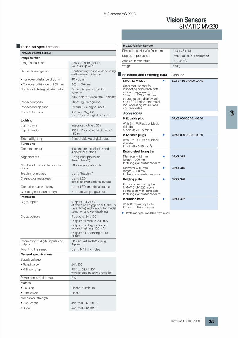
Image acquisition CMOS sensor (color);640 x 480 pixels
Size of the image field Continuously variable; dependingon the object distance
• For object distance of 50 mm 40 x 30 mm
• For object distance of 250 mm 200 x 150 mm
Number of distinguishable colors Depending on inspectionseverity;
2048 colors / 64 colors / 16 colors
Inspection types Matching, recognition
Inspection triggering External; via digital input
Output of results "OK" and "N_OK";via LEDs and digital outputs
L
L
i
i
g
g
h
h
t
t
i
i
n
n
g
g
Light source Integrated white LEDs
Light intensity 800 LUX for object distance of150 mm
External lighting Controllable via digital output
FFuunnccttiioonnss
Operator control 4-character text display and4 operator buttons
Alignment tool Using laser projection(laser class 2)
Number of models that can bestored
16; using digital inputs
Teach-in of models Using "Teach-in"
Diagnostics messages Using LED,text display and digital output
Operating status display Using LED and digital output
Disabling operation of keys Possible using digital input
I
In
nt
te
e
r
r
f
f a
a
c
c
e
e
s
s
Digital inputs 6 inputs, 24 V DCof which one trigger input (100 µsdelay time) and 5 inputs for modelselection and key disabling
Digital outputs 5 outputs; 24 V DC
Outputs for results, 500 mA
Outputs for diagnostics andexternal lighting, 100 mA
Outputs for operating status,
20mAConnection of digital inputs andoutputs
M12 socket and M12 plug,8-pole
Mounting the sensor Using M4 fixing holes
G
G
e
e
n
n
e
e
r
r
a
a
l
l
s
s
p
p
e
e
c
c
i
i
f
f
i
i
c
c
a
a
t
t
i
i
o
o
n
n
s
s
Supply voltage
• Rated value 24 V DC
• Voltage range 20.4 … 28.8 V DC;with reverse polarity protection
Power consumption max. 2 A
Material
• Housing Plastic, aluminum
• Lens cover Plastic
Mechanical strength
• Oscillations acc. to IEC61131-2
• Shock acc. to IEC61131-2
Dimensions (H x W x D) in mm 113 x 35 x 90
Degree of protection IP65 acc. to DIN EN 60529
Ambient temperature 0 … 45 °C
Weight 430 g
SSIIMMAATTIICC MMVV222200 } 6 6GGFF55 111100--00AAAA0000--00AAAA00
Color mark sensor forinspecting colored objects;size of image field 40 x30 mm … 200 x 150 mm;operating unit, display unitand LED lighting integrated;incl. operating instructionsand templates
A
Ac
c c
c e
e s
s s
s o
o r
r i
i e
e s
s
M
M
1
1
2
2
c
c
a
a
b
b
l
l
e
e
p
p
l
l
u
u
g
g
3
3
R
R
X
X
8
8
0
0
0
0
0
0
-
-
0
0
C
C
B
B
8
8
1
1
-
-
1
1
G
G
F
F
0
0
With 5 m PUR cable, black,shielded,8-pole (8 x 0.25 mm2)
M
M
1
1
2
2
c
c
a
a
b
b
l
l
e
e
p
p
l
l
u
u
g
g
s
s }
3
3
R
R
X
X
8
8
0
0
0
0
0
0
-
-
0
0
C
C
D
D
8
8
1
1
-
-
1
1
G
G
F
F
0
0
With 5 m PUR cable, black,shielded,8-pole (8 x 0.25 mm2)
RRoouunndd--sstteeeell ff iixxiinngg bbaarr
Diameter = 12 mm,length = 200 mm,for fixing system for sensors
} 3 3RRXX77 331155
Diameter = 12 mm,length = 300 mm,for fixing system for sensors
} 3 3RRXX77 331166
H
H
o
o
l
l
d
d
i
i
n
n
g
g
p
p
l
l
a
a
t
t
e
e }
3
3
R
R
X
X
7
7
3
3
2
2
6
6
For accommodating theSIMATIC MV 220, use inconnection with fixing bar;for fixing system for sensors
M
Mo
ou
un
nt
ti
in
ng
g
b
ba
as
se
e }3
3R
RX
X7
7
3
32
22
2
With 12 mm receptaclefor sensor fixing system
MMVV222200 VViissiioonn SSeennssoorr
© Siemens AG 2008

8/21/2019 SISTEME DE PROCESARE A IMAGINII SIMATIC MV.pdf
http://slidepdf.com/reader/full/sisteme-de-procesare-a-imaginii-simatic-mvpdf 6/16
Vision SensorsSIMATIC MV220
3 / 6 Siemens FS 10 · 2009
3
DDiimmeennssiioonnss
SScchheemmaattiiccss
MV220 Vision Sensor, X1 interface
MV220 Vision Sensor, X2 interface
MV220 Vision Sensor, socket pin assignment
MV220 Vision Sensor, plug pin assignment
7 5
3 5
9 0
98
87,4
100
6 2
7 , 5
113,4
6
40
FS10_00158
M4FS10_00163
3GN (M)
WH (L+)1
8RD (RDY)
7BU (TRG)
6PK (DIAG)
5 GR (TRG OUT)
4 YE (OK)
2 BN (N_OK)
FS10_00164
8RD
WH1
7BU
6 PK (DISA)
5GR (SEL3)
4YE (SEL2)
3 GN (SEL1)
2 BN (SEL0)
FS10_00165
4
21
6
7
8
3
5
FS10_00166
6
12
4
3
8
7
5
© Siemens AG 2008

8/21/2019 SISTEME DE PROCESARE A IMAGINII SIMATIC MV.pdf
http://slidepdf.com/reader/full/sisteme-de-procesare-a-imaginii-simatic-mvpdf 7/16
Vision SensorsSIMATIC MV230
3 / 7Siemens FS 10 · 2009
3
OOvveerrvviieeww
• Compact image processing sensor for the automatic testing ofobjects based on the specific surface contour or profile.
• A synthesis of high-performance image processing technol-ogy with simple, compact sensors
• High stability against ambient light
• For applications in manufacturing, the packaging industry andin the construction of special machines and serial machines
• Process-oriented implementation thanks to degree of protec-tion IP65
• Integration in plant automation using digital inputs and outputs
• Quick familiarization with task thanks to the teach-in function
BBeenneeff iittss
• Degree of protection IP65 makes use in harsh industrialenvironments possible
• Costs for shielding against ambient light can normally besaved due to their high stability against ambient light
• Short changeover times thanks to simple model change- 16 inspection models can be taught- inspection models are selected using digital inputs
• Rapid startup thanks to Teach In- no image processing knowledge necessary- effective start-up and maintenance functions using diagnos-
tics, checksums and statistical information
• Prevention of unauthorized operation through button disabling
AApppplliiccaattiioonn
The SIMATIC MV230 height profile sensor is a complete imageprocessing system for the automatic inspection of objects basedon the specific height contour or profile. The split-beam methodand laser projection on which it is based supports extremely rug-ged and reliable inspection.It completes the product portfolio in the low-end image process-ing segment and high-end segment of conventional sensors.
Its performance capability, simplicity and in particular the rug-gedness of the test procedures can be used for inspection tasksthat are too complex for other image processing systems andthat must be disregarded for cost reasons.
The module is used in:
• Production and assembly systems for automotive suppliersand electrical engineering;checking, parts recognition and position inspection during
assembly
• Packaging machinesChecking for presence, parts recognition and checking thelocation of objects
• General machine constructionChecking for presence, parts recognition and checking thelocation of objects
D
D
e
e
s
s
i
i
g
g
n
n
The SIMATIC MV230 height profile sensor combines all thecomponents required for the test in a compact enclosure:
• Rugged plastic/metal enclosure with degree of protectionIP65
• Digital camera:- CMOS chip- Resolution of 750 x 480 pixels
• Integrated laser line of up to 75 mm in length
• Operator controls and displays:- Input keys
- Display- LED displays
• M12 plug and socket with connections for:- Power supply- Digital inputs and outputs
• M4 fastening holes for mechanical fixing system for industrialsensors
FFuunnccttiioonn
The following functions are available:
• Training of models based on a Good object
• Inspecting an object using the features extracted duringteach-in
• Inspection of the object supplies a good/bad statement inaccordance with the set threshold values (Q-LIMIT)
• Inspection results are output on two digital outputs:- OK: Compatibility of the object with the saved model is
greater than or equal to the set threshold value- N_OK: Compatibility of the object with the saved model is
less than the set threshold value
O
O p
p e
e r
r a
a t
t i
i n
n g
g
p
p r
r i
i n
n c
c i
i p
p l
l e
e
Manual alignment of the sensor is supported by the visible laserline.
The inspection task is trained by presenting a Good object. Theobject to be inspected or the object area to be inspected ispositioned under the laser line.
For smaller objects, the length of the laser line range that can be
evaluated can be reduced. The teach-in result is saved underone of 16 data records (model number).
The learned inspection task can then be tested immediately intest mode.
To start the evaluation mode you have to select a trained objectdata record and switch to "RUN" mode.
After triggering, the sensor starts evaluation.On the basis of the learned threshold values and the actual val-ues of the evaluation, a result is output on the OK digital outputs(Good) or N_OK (Bad).
The inspection task can be changed by selecting a differentdata record (model) in "RUN" mode.
Any sensor faults or errors in operating the sensor are reportedin the diagnostics. Evaluation mode continues or is terminated
depending on the type of error.
© Siemens AG 2008

8/21/2019 SISTEME DE PROCESARE A IMAGINII SIMATIC MV.pdf
http://slidepdf.com/reader/full/sisteme-de-procesare-a-imaginii-simatic-mvpdf 8/16
Vision SensorsSIMATIC MV230
3 / 8 Siemens FS 10 · 2009
3
TTeecchhnniiccaall ssppeecciiff iiccaattiioonnss
MMVV223300 VViissiioonn SSeennssoorr
IImmaag
ge
e c
ca
ap
pt
tu
urree a
anndd e
evvaal
lu
ua
at
ti
io
onn
Image sensor CMOS sensor; 750 x 480 pixels
Operating distance 210 … 310 mm
Size of the image field 75 x 100 mm(for 310 mm operating distance)
Measuring principle Split-beam(laser-based triangulation)
Test type Profile evaluation
Accuracy/physical resolution Height accuracy: 0.5 mm;
Width accuracy: 0.2 mm
Triggering for image capture Internal, freewheeling trigger;external trigger through digitalinput TRG
Max. cycle time 50 ms
Response time 16 ms
Output of results "OK" and "N_OK";via LEDs and digital outputs
L
L
i
i
g
g
h
h
t
t
i
i
n
n
g
g
Light source Laser diode, red light
Laser protection class 2M (IEC 825-1, EN 60825-1)
Length of laser line 50 … 75 mm
FFuunnccttiioonnss
Operation 4-character text display and4 operator buttons
Number of models that can betaught
16
Teach-in of models "Teach-in" on the sensor
Diagnostic messages available;using LED, text display anddigital output
Operating status display available;using LED and digital output
Disabling operation of keys possible;using digital input
Checking the set values possible using global andmodel-specific checksums
Statistics function available
IInntteerrff aacceess
Digital inputs 6 inputs;for trigger (TRG), model selection(SEL0-3) and button disable
(DISA)Rated voltage 24 V DC
Input current typ. 7 mA
Voltage range Signal 1: 15 ... 30 V
Signal 0: -3 ...5 V
Input delay 3 ms typical (input TRG 0.1 ms)
Input characteristics curve IEC1131, Type 1
Digital outputs 4 outputs;for result output (OK, N_OK),diagnostics (DIAG) and readystatus (RDY)
Output voltage for "1" signal L+ (-0.8 V)
Output current for "1" signal 500 mA (outputs OK, N_OK)
100 mA (DIAG)20 mA (RDY)
Short-circuit protectionat the outputs
Yes, electronic
G
Ge
enneerraal
l d
da
at
ta
a
Supply voltage L+
• Nominal value 24 V DC
• Voltage range 20.4 … 28.8 V DC,with reverse polarity protection
Power consumption max. 2 A
Mechanical strength
• Vibration acc. to IEC61131-2
• Shock acc. to IEC61131-2
Material
• Enclosure Plastic, aluminum
• Lens cover plastic
Dimensions (H x W x D) in mm 161 x 35 x 112Degree of protection IP65 to DIN EN 60529
Ambient temperature 0 … 45 °C,no moisture condensation
Weight 450 g
MMVV223300 VViissiioonn SSeennssoorr
© Siemens AG 2008

8/21/2019 SISTEME DE PROCESARE A IMAGINII SIMATIC MV.pdf
http://slidepdf.com/reader/full/sisteme-de-procesare-a-imaginii-simatic-mvpdf 9/16
Vision SensorsSIMATIC MV230
3 / 9Siemens FS 10 · 2009
3
SSeelleeccttiioonn
aanndd
OOrrddeerriinngg
ddaattaa Order No.
} Preferred type, available from stock.
DDiimmeennssiioonnss
S
S
c
c
h
h
e
e
m
m
a
a
t
t
i
i
c
c
s
s
Plug connection for interface X1 and core color for M12 cable socket,8-pin, length 5 m (Order No.: 3RX8 000-0CB81-1GF0)
Plug connection for interface X2 and core color for M12 cable plug,8-pin, length 5 m (Order No.: 3RX8 000-0CD81-1GF0)
Pin assignment X1, M8 connection for cable sockets
Pin assignment X2, M8 connection for cable plug
S
SIIMMAATTIICC
MMVV223
30
0 }6
6G
GFF22 11110
0-
-0
0BBAA0
00
0-
-0
0AAAA0
0
Image processing sensorfor the automatic inspectionof objects and their positionbased on the specific sur-face contour and profile
A
A
c
c
c
c
e
e
s
s
s
s
o
o
r
r
i
i
e
e
s
s
MM1
122
c
ca
abbl
lee
ppl
lu
ugg }
3
3RRXX8
8
0
00
00
0-
-0
0CCBB8
81
1-
-1
1G
GFF0
0
With 5 m PUR cable, black,shielded,8-pole (8 x 0.25 mm2)
MM1122 ccaabbllee pplluuggss } 3 3RRXX88 000000--00CCDD8811--11GGFF00
With 5 m PUR cable, black,shielded,8-pole (8 x 0.25 mm2)
RRo
ou
unndd-
-s
st
teeeel
l
f
f i
ixxi
inngg
bba
ar
r
Diameter = 12 mm,length = 200 mm,for fixing system for sensors
}
3
3
R
R
X
X
7
7
3
3
1
1
5
5
Diameter = 12 mm,length = 300 mm,for fixing system for sensors
}
3
3
R
R
X
X
7
7
3
3
1
1
6
6
HHo
ollddiinngg
pplla
at
tee } 3
3RRXX77
3
32266
For accommodating theSIMATIC MV230, use inconnection with fixing bar;for fixing system for sensors
MMo
ou
unnt
ti
inngg
bba
as
see }
3
3RRXX77
3
32222
With 12 mm receptacle forsensor fixing system
SIMATIC
MV230
s
112,5
1 5 2
4 0
1 3 6
62
M4
6 7
F S 1 0_
0 0 2 3 6
9035,376 7
FS10_00240
3GN (M)
WH (L+)1
8RD (RDY)
7BU (TRG)
6PK (DIAG)
5 GR
4 YE (OK)
2 BN (N_OK)
FS10_00164
8RD
WH1
7BU
6PK (DISA)
5GR (SEL3)
4YE (SEL2)
3 GN (SEL1)
2 BN (SEL0)
FS10_00166
6
12
4
3
8
7
5
FS10_00165
4
21
6
7
8
3
5
© Siemens AG 2008

8/21/2019 SISTEME DE PROCESARE A IMAGINII SIMATIC MV.pdf
http://slidepdf.com/reader/full/sisteme-de-procesare-a-imaginii-simatic-mvpdf 10/16
Vision SensorsSIMATIC VS120
3 / 10 Siemens FS 10 · 2009
3
OOvveerrvviieeww
• Vision sensor for object finding and object size testing inreflected light
• VS120 finds and checks different objects and / or patterns,e.g.:- printed symbols (product markings on labels, packaging,
etc. )- injection-molded parts,- ceramic elements,- ...
• Can be used in principle for the following applications:- position detection for Pick&Place applications,- checking the presence and position of objects in production,
- checking the orientation of objects in infeed systems• Easy configuration through presentation of the good object to
be recognized. "Training" is done automatically by activatingthe training function of the unit.
• Parameter definition is done using the web-based operatinginterface and can be run on various platforms with the follow-ing requirements:- Browser (IE5.5 or higher),- JAVA-VM (MS, SUN).
• The web-based operator interface is also used for controllingthe device from an HMI device. The same prerequisites applyhere concerning the Browser and JAVA VM.
• Remote maintenance concept using web-based operatorinterface.
• Remote controlled with integrated digital inputs, PROFIBUS or
PROFINET IO.• Can be supplied as a complete package in several variations
for different object sizes
A
A
p
p
p
p
l
l
i
i
c
c
a
a
t
t
i
i
o
o
n
n
The intelligent vision sensor can be used for the followingapplications:
• Determining the position for Pick & Place applications
• Checking the presence and position of objects in production
• Checking the orientation of objects in infeed systems
Examples of possible inspection tasks and inspection objects:
• Checking the presence and position of symbols (warnings)and logos (corporate logos) on print media and packaging
• Checking the presence and position of objects in productionfor the quality assurance of assembly steps
• Checking the orientation of assembly items in infeed systems
DDeessiiggnn
The SIMATIC VS 120 vision sensor offers the following imagefield sizes:
• 70 x 50 mm fixed-focus sensor head
• 40 x 30 mm fixed-focus sensor head
• Variable field of view with C/CS-Mount sensor head
The following components are required for use of the fixed-focusversion of the SIMATIC VS120 vision sensor and are included inthe scope of delivery:
• Sensor head
• Front lighting in the form of a ring light matched to the applica-tion and sensor head
• Evaluation unit
• Connecting cables
• CD with configuration software and assembly/operatinginstructions
To start up the fixed focus version you also need the followingitems (not included in the scope of delivery):
• Ethernet cable (see "Accessories") for connecting the evalua-tor to any web client. The web client, e.g. a PC with webbrowser installed, is used to adjust the sensor head and thelighting.
The following components are required for use of the C/CSmount version of the SIMATIC VS120 vision sensor and areincluded in the scope of delivery:
• Sensor head (without lens!)
• Evaluation unit
• Connecting cables (no connecting cable for lighting!)
• CD with configuration software and assembly/operatinginstructions
To start up the C/CS-Mount version you also need the followingitems (not included in the scope of delivery):
• C/CS-Mount lens with the required imaging properties
• Suitable light source and suitable connecting cable(see accessories)
• Ethernet cable (see "Accessories") for connecting the evalua-tor to any web client. The web client, e.g. a PC with webbrowser installed, is used to adjust the sensor head and thelighting.
SS ee nn ss oo rr hh ee aa dd
The sensor head is equipped with:
• Extruded aluminium housing to degree of protection IP65(fixed-focus version)
• CCD chip (640 x 480 quadratic pixels)• Lens, permanently installed and non-adjustable
(fixed focus version)
• Interface for digital transmission of image data to theevaluation unit
A sensor head for C/CS-Mount lenses is additionally available.
EE vv aa ll uu aa tt ii oo nn uu nn ii tt
The evaluation unit has:
• Plastic housing, designed for cabinetless construction (IP40)
• Connections for- Supply voltage 24 V DC- Lighting- Sensor head
- Digital inputs and outputs- Ethernet interface (DHCP-Client, DHCP-Server,fixed IP address)
- PROFIBUS DP
• 4-line text display for operator prompting
© Siemens AG 2008

8/21/2019 SISTEME DE PROCESARE A IMAGINII SIMATIC MV.pdf
http://slidepdf.com/reader/full/sisteme-de-procesare-a-imaginii-simatic-mvpdf 11/16
Vision SensorsSIMATIC VS120
3 / 11Siemens FS 10 · 2009
3
• 6 keys for operating the unit
• User guidance with web-based operator interface(HTML, JAVA VM)
• Access protection by means of password.The following communication services are included:
• PROFINET IO (slave)
• PROFIBUS DP V0 (slave),
• TCP/IP native
The analysis is carried out by a powerful digital signal processor.
FF rr oo nn tt ll ii gg hh tt ii nn gg
• Designed as ring light pushed onto sensor head
• Can be dismounted, and secured with different orientation onthe machine
• Housing with degree of protection IP65
• Equipped with red LEDs
• Operation in flash mode• Power control for the flash integrated in the light
F
F
u
u
n
n
c
c
t
t
i
i
o
o
n
n
• Training the object test parameters using one or more goodobjects
• Testing an object and/or pattern with the features taken fromthe training
• Testing can be performed on stationary and moving objects
• Checking for a match with the reference provides a good/poorindication after comparison with set-value criteria
• Test results output to three control outputs:- OK:
trained object and/or pattern found based on features;
degree of match greater than set value- N_OK:trained object and/or pattern NOT found based on features;degree of match NOT greater than set value
• Position information output via PROFIBUS DP, PROFINET IO,Ethernet or with converter to RS 232 interface
• Integrated DI/O enables "stand-alone" operation withoutadditional controller.
• Remote control via PROFIBUS DP, PROFINET IO, DI/O orEthernet
• Remote maintenance via web-based operator interfaceIntranet or Internet:- monitoring (live image in read mode)- diagnostics (fault image, log information, ...)- system administration (software update, ...)- error analysis for troubleshooting for faulty readings
• Actuation of ring lighting
M
M
o
o
d
d
e
e
o
o
f
f
o
o
p
p
e
e
r
r
a
a
t
t
i
i
o
o
n
n
The following steps are required for using the SIMATIC VS120:
• Mount the vision sensor and lighting.
• Manual alignment of the camera, lighting check:This is handled with the web-server integrated in the unit andthe web-based operator interface contained within. The oper-ator interface displays the camera image. In the setup phase,the sensor head can be aligned with reference to the live im-age in the user interface. The user interface executes on anyPC with Microsoft Internet Explorer and JAVA VM installation.If the sensor head adjustment is complete, the vision sensorautomatically takes over the following procedures:- optimization of lighting control.
- "Training" the image processing parameters by applying areference object
- the result of the training is stored under one of the 64 datarecords
• Starting the evaluation operation requires loading a trainedobject record and changing into the "RUN" operating mode.The VS120 starts the evaluation after triggering.
• Depending on the trained set values and the actual values ofthe evaluation, one of the digital control outputs OK (goodresult) or N_OK (poor result) is set.
The position information is output via the PROFIBUS DP,PROFINET IO or Ethernet interface.
P
P
r
r
o
o
g
g
r
r
a
a
m
m
m
m
i
i
n
n
g
g
SIMATIC VS120 is not programmed and parameters are notdefined as on standard image processing systems. It is trainedfor its special task, finding and testing a special object. TheSIMATIC VS120 is shown a good object and the device is"trained" to this object.
The training procedure can be performed while a conveyorsystem is running.
Up to 64 different data records can be stored in the device and
can be called up at any time by the operator or can also becalled up through an external controller.
T
T
e
e
c
c
h
h
n
n
i
i
c
c
a
a
l
l
s
s
p
p
e
e
c
c
i
i
f
f
i
i
c
c
a
a
t
t
i
i
o
o
n
n
s
s
S
S
I
I
M
M
A
A
T
T
I
I
C
C
V
V
S
S
1
1
2
2
0
0
V
V
i
i
s
s
i
i
o
o
n
n
S
S
e
e
n
n
s
s
o
o
r
r
S
Seenns
so
or
r
hheea
add
Image capture CCD chip ¼", 640 x 480 squarepixels; full frame shutter with auto-matic exposure time
Image data transfer Triggered frame transfer
Available versions • Fixed lens system for twodifferent field of view sizes andmounting positions
• One C/CS-mount versionwithout lens.
• Large field of view Size of field of view:70 x 50 mmfor object sizes up to approx.:60 x 40 mmOperating distance: 120 mm
• Small field of view Size of field of view:40 x 30 mmfor object sizes up to approx.:34 x 24 mmOperating distance: 85 mm
• Variable field of view Lens can be selected by the user;hence freely selectable field ofview size and object sizeOperating distance: dependenton the lens
Enclosure Aluminum profile casing,
anodized black
Dimensions (W x H x D) in mm 42 x 42 x 100
Degree of protection IP65 according toDIN EN 60529 / VDE 0470-1
Ambient temperature 0 … 50 °C
Mechanical strength
• Vibrations 1 g (60 … 500 Hz)
• Shock 70 g (6 ms, 3 shocks)
© Siemens AG 2008
8/21/2019 SISTEME DE PROCESARE A IMAGINII SIMATIC MV.pdf
http://slidepdf.com/reader/full/sisteme-de-procesare-a-imaginii-simatic-mvpdf 12/16
Vision SensorsSIMATIC VS120
3 / 12 Siemens FS 10 · 2009
3 SSeelleeccttiioonn
aanndd
OOrrddeerriinngg
ddaattaa Order No.
} Preferred type, available from stock.
B: Subject to export regulations AL = N and ECCN = EAR99S
AAcccceessssoorriieess
Accessories for SIMATIC VS120 can be found startingwith page 6/14.
S
SIIMMAATTIICC VVS
S11220
0 VViissiioonn S
Seennsso
or
r
LLiigghht
tiinngg
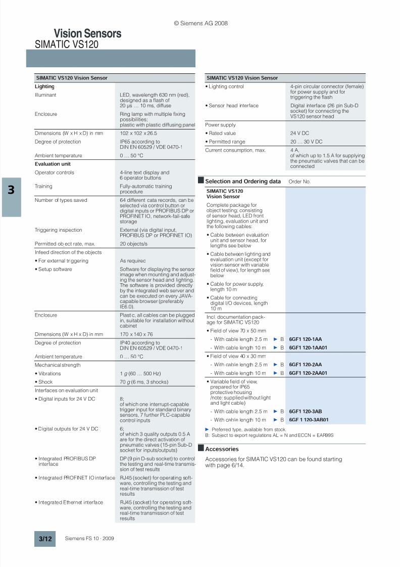
Illuminant LED, wavelength 630 nm (red),
designed as a flash of20 µs … 10 ms, diffuse
Enclosure Ring lamp with multiple fixingpossibilities;plastic with plastic diffusing panel
Dimensions (W x H x D) in mm 102 x 102 x 26.5
Degree of protection IP65 according toDIN EN 60529 / VDE 0470-1
Ambient temperature 0 … 50 °C
EEvvaalluuaattiioonn uunniitt
Operator controls 4-line text display and6 operator buttons
Training Fully-automatic trainingprocedure
Number of types saved 64 different data records, can beselected via control button ordigital inputs or PROFIBUS DP orPROFINET IO, network-fail-safestorage
Triggering inspection External (via digital input,PROFIBUS DP or PROFINET IO)
Permitted object rate, max. 20 objects/s
Infeed direction of the objects
• For external triggering As required
• Setup software Software for displaying the sensorimage when mounting and adjust-ing the sensor head and lighting.The software is provided directlyby the integrated web server and
can be executed on every JAVA-capable browser (preferablyIE6.0).
Enclosure Plastic, all cables can be pluggedin, suitable for installation withoutcabinet
Dimensions (W x H x D) in mm 170 x 140 x 76
Degree of protection IP40 according toDIN EN 60529 / VDE 0470-1
Ambient temperature 0 … 50 °C
Mechanical strength
• Vibrations 1 g (60 … 500 Hz)
• Shock 70 g (6 ms, 3 shocks)
Interfaces on evaluation unit
• Digital inputs for 24 V DC 8;of which one interrupt-capabletrigger input for standard binarysensors, 7 further PLC-capablecontrol inputs
• Digital outputs for 24 V DC 6;of which 3 quality outputs 0.5 Aare for the direct activation ofpneumatic valves (15-pin Sub-Dsocket for inputs/outputs)
• Integrated PROFIBUS DPinterface
DP (9 pin D-sub socket) to controlthe testing and real-time transmis-sion of test results
• Integrated PROFINET IO interface RJ45 (socket) for operating soft-ware, controlling the testing andreal-time transmission of testresults
• Integrated Ethernet interface RJ45 (socket) for operating soft-ware, controlling the testing andreal-time transmission of testresults
S
SIIMMAATTIICC VVS
S11220
0 VViissiioonn S
Seennsso
or
r
• Lighting control 4-pin circular connector (female)for power supply and for
triggering the flash• Sensor head interface Digital interface (26 pin Sub-D
socket) for connecting theVS120 sensor head
Power supply
• Rated value 24 V DC
• Permitted range 20 … 30 V DC
Current consumption, max. 4 A,of which up to 1.5 A for supplyingthe pneumatic valves that can beconnected
S
SIIMMAATTIICC
VVS
S11220
0
VVi
issi
ioonn SSeennssoorr
Complete package forobject testing; consistingof sensor head, LED frontlighting, evaluation unit andthe following cables:
• Cable between evaluationunit and sensor head, forlengths see below
• Cable between lighting andevaluation unit (except forvision sensor with variablefield of view), for length seebelow
• Cable for power supply,length 10 m
• Cable for connectingdigital I/O devices, length10 m
Incl. documentation pack-age for SIMATIC VS120
• Field of view 70 x 50 mm
- With cable length 2.5 m } B 6 6G
GFF11
11220
0-
-11AAAA
- With cable length 10 m } B 6
6G
GFF1
1
1
1220
0-
-1
1AAAA0
01
1
• Field of view 40 x 30 mm
- With cable length 2.5 m } B 6 6GGFF11 112200--22AAAA
- With cable length 10 m } B 6 6GGFF11 112200--22AAAA0011
• Variable field of view,prepared for IP65protective housing
/note: supplied without lightand light cable)
- With cable length 2.5 m } B
6
6
G
G
F
F
1
1
1
1
2
2
0
0
-
-
3
3
A
A
B
B
- With cable length 10 m } B
6
6
G
G
F
F
1
1
1
1
2
2
0
0
-
-
3
3
A
A
B
B
0
0
1
1
© Siemens AG 2008

8/21/2019 SISTEME DE PROCESARE A IMAGINII SIMATIC MV.pdf
http://slidepdf.com/reader/full/sisteme-de-procesare-a-imaginii-simatic-mvpdf 13/16
Vision SensorsLenses
3 / 13Siemens FS 10 · 2009
3
OOvveerrvviieeww
Using a lens appropriate to the respective image evaluationtask, the size of the image field at a desired working distance isdetermined for the camera image. In order to achieve reproduc-ible statements from the image evaluation concerning the posi-tion, measurement or quality, the geometry and light intensity forthe image must be kept constant within the permissible toler-ances. For this reason, only lenses with a fixed focal length,aperture and focus are usually used. Motorized zoom, automaticaperture or autofocus are more detrimental than helpful.
AApppplliiccaattiioonn
• Measuring tasks and form recognitionFor high-precision, reproducible measurement of geometricvariables, a full-format image is necessary to satisfy resolution
requirements. Lenses must therefore be selected that havelow distortion, high modulation depth and a small angle ofview. Telecentric lenses are recommended for objects thathave protrusions in the direction of the lens.
• Quality control and parts recognitionFor recognition or inspection of the features of an object on thesurface, the quality of the results depends on contrast andlack of distortion of the image. Macro lenses are often used atclose range.
• Code and text readingThe recognition algorithms are tolerant to variations in formand size of the patterns. The requirements on quality of theoptics are not very high. Low-cost lenses contribute towardsthe cost-effectiveness of image evaluation systems especiallywhen they are used in more than one reading station.
• Check for completeness and handling
For localization and pattern recognition, the same criteriaapply as for measurement tasks or parts recognition.
FFuunnccttiioonn
II mm aa gg ee tt y y pp ee ss
The optical path of the lens is defined by its construction.For
s
s
p
p
h
h
e
e
r
r
i
i
c
c
a
a
l
l
l
l
e
e
n
n
s
s
e
e
s
s the solid angle depends on the focallength, focus adjustment and aperture; all rays run through thefocal point of the lens (central projection). Objects that are fur-ther away from the lens are depicted smaller; objects that arecloser to the lens are depicted larger:
The required image field size (height and width of the image),the size of the sensor chip and the focal length of the lens deter-mine the operating distance:
dd
==
((ff xx
IISS)) / / bb
d = Operating distance (distance from lens to test object) in mm
f = Focal length of the lens in mm
IS = Size of image in the plane of the test object in mmb = effective dimensions of the sensor in mm
In the case of lenses used in image processing systems, the fo-cal length is fixed, the aperture and focus settings can be fixed.The focal length, the maximum focal aperture and the focusingrange are normally specified on the lenses.
F
F o
o c
c a
a l
l
d
d i
i s
s t
t a
a n
n c
c e
e
The focal length makes a statement about the angle of the imagefield or magnification of the lens.
The focal length of the lens is determined by the size of therequired image field and the size of the camera chip when aspecific distance has to be maintained. The most common chipsizes in cameras today are ", " and ". If the distance to theobject lies below the adjustable focusing range of the lens, i.e.at close range, the focus can be adjusted using intermediaterings.
If the seating dimensions are designed for CS-Mount lenses inthis camera, as for VS 100, a 5 mm intermediate ring can beused to adjust a C-Mount lens.
A
A
p
p
e
e
r
r
t
t
u
u
r
r
e
e
Reduction of the light intensity by interrupting the optical path.
FF oo cc uu ss
Setting the focus of the lens to a specific distance.
DD ee pp tt hh oo ff ff ii ee ll dd
Depth of field is the area within which (in front of and behind theobject) that is displayed with sufficient sharpness of focus. The
larger the aperture (the smaller the aperture number), thesmaller the depth of field.
Lenses with a larger focal length have a smaller depth of field,the effect is considerable for images at close range.
12 / 1
3 / 14 /
© Siemens AG 2008

8/21/2019 SISTEME DE PROCESARE A IMAGINII SIMATIC MV.pdf
http://slidepdf.com/reader/full/sisteme-de-procesare-a-imaginii-simatic-mvpdf 14/16
Vision SensorsLenses
3 / 14 Siemens FS 10 · 2009
3
LLee nn ss tt y y pp ee ss
Lenses with smaller focal length are called wide-angle lenses,they can also be used at short operating distances, but produce
intense distortion of the image. At a suitable distance, they havea large image field.
Lenses with a long focal length are called telephoto lenses; theyhave a large magnification but cannot be focused at closerange, so macro lenses are used that can be focused by meansof large telescopic extensions or intermediate rings. At a suitabledistance, they have a small image field.
In the case of telecentric lenses, at least the optical path at theobject end is almost parallel (parallel projection). This means
that objects at different distances are depicted in the same size.Objects can, however, only be displayed that are smaller than
the diameter of the lens. It is not possible to adjust the range offocus with these lenses.
The optical characteristics can be restricted by means of opticalfilter glasses to counteract distortion in the image. Colored filterslimit the spectral range, gray filters limit the light intensity and po-larization filters restrict the transmission plane. Filters of this typecan be attached either by using the internal thread or the flangeon the front of the lens. The holder for the filter glass is designedto fit the lens.
SSeelleeccttiioonn
aanndd
OOrrddeerriinngg
ddaattaa Order No. Order No.
} Preferred type, available from stock.
K: Subject to export regulations AL = 9I999 and ECCN = EAR99H
M: Subject to export regulations AL = 9I999 and ECCN = N
LLeennsseess ff oorr rreeaaddiinngg ccooddee
a
anndd
ppllaaiinn
t
teexxt
t
a
anndd
ppaarrttss rreeccooggnniittiioonn
with fixed focal length, adjust-able aperture and focus, withlocking screw
• Mini lens 8.5 mm, 1:1.5D = 42 mm, L = 47 mm;successor type for
6GF9001-1BE
} K 6 6G
GFF9
90
00
011--11BBEE0
011
• Mini lens 12 mm, 1:1.4D = 29.5 mm, L = 35.7 mm
} K
6
6
G
G
F
F
9
9
0
0
0
0
1
1
-
-
1
1
B
B
L
L
0
0
1
1
• Mini lens 16 mm, 1:1.4D = 29.5 mm, L = 37.2 mm;successor type for6GF9001-1BF
} K
6
6
G
G
F
F
9
9
0
0
0
0
1
1
-
-
1
1
B
B
F
F
0
0
1
1
• Mini lens 25 mm, 1:1.4D = 29.5 mm, L = 38.9 mm;Successor type for6GF9001-1BG
} K 6 6GGFF99000011--11BBGG0011
• Mini lens 35 mm, 1:1.6D = 29.5 mm, L = 41.4 mm
} K 6 6G
GFF9
90
00
011--11BBHH0
011
• Mini lens 50 mm, 1:2.8D = 29.5 mm, L = 38.0 mm;successor type for
6GF9001-1AH
} K 6 6G
GFF9
90
00
011-
-11BBJJ0
011
• Mini lens 75 mm, 1:2.8D = 34.0 mm, L = 63.6 mm
} K
6
6
G
G
F
F
9
9
0
0
0
0
1
1
-
-
1
1
B
B
K
K
0
0
1
1
CCSS--MMoou
unntt ff oorr CC--MMoou
unntt
a
adda
appt
teer
r
r
riinngg
55
m
mm
m
} K 6 6G
GFF990
00
011--11AAPP0
022
AAc
cc
cees
ss
so
or
riiees
s
f
f o
or
r
u
ut
tiilliizziinngg
t
thhee
mmiinnii lleennsseess aatt cclloossee rraannggee::
• Set of intermediate ringswith 0.5 mm, 1.0 mm,5.0 mm, 10.0 mm, 20.0 mm,40 mm rings with 31 mmdiameter C thread, attachedbetween the lens and thecamera body for shots in themacro range
} K
6
6
G
G
F
F
9
9
0
0
0
0
1
1
-
-
1
1
B
B
U
U
AAc
cc
cees
ss
so
or
ri
iees
s
f
f o
or
r
u
ut
ti
il
li
izzi
inngg
tthhee mmiinnii lleennsseess iinn tteelleepphhoottoo
rraannggee::
• Focal length extender,D = 30.5 mm, L = 17.9 mmwith C thread, attachedbetween the lens and thecamera body for extendingthe focal length by a factorof 2
} K 6 6G
GFF9
90
00
011-
-11BBVV
• Lens intermediate ring15 mm
M
6
6
G
G
F
F
9
9
0
0
0
0
1
1
-
-
1
1
A
A
P
P
0
0
1
1
F
F
i
i
l
l
t
t
e
e
r
r
f
f
o
o
r
r
u
u
t
t
i
i
l
l
i
i
z
z
a
a
t
t
i
i
o
o
n
n
o
o
f
f
t
t
h
h
e
e
m
m
i
in
n
i
i
l
le
e
n
n
s
s
e
e
s
s
i
in
n
t
t
h
h
e
e
l
li
im
m
i
it
t
e
e
d
d
f
f i
ie
el
ld
d
o
of
f
v
vi
ie
ew
w:
:
• Infrared filter for lenses6GF9001-1BF01, -1BG01,-1BH01, -1BJ01, -1BL01
} M 6 6GGFF99000011--22AADD
• Blue filter for lenses6GF9001-1BF01, -1BG01,-1BH01, -1BJ01, -1BL01
} M 6 6G
GFF9
90
00
011-
-22AAEE
• Polarization filter for lenses6GF9001-1BF01, -1BG01,-1BH01, -1BJ01, -1BL01
} M 6 6G
GFF9
90
00
011-
-22AAFF
© Siemens AG 2008

8/21/2019 SISTEME DE PROCESARE A IMAGINII SIMATIC MV.pdf
http://slidepdf.com/reader/full/sisteme-de-procesare-a-imaginii-simatic-mvpdf 15/16

8/21/2019 SISTEME DE PROCESARE A IMAGINII SIMATIC MV.pdf
http://slidepdf.com/reader/full/sisteme-de-procesare-a-imaginii-simatic-mvpdf 16/16
Vision SensorsLenses
3/16 Si FS 10 2009
3
NNootteess
© Siemens AG 2008


