SIPART DR21 6DR 210*--* - vision-solutions.ca · SIPART DR21 C73000-B7476-C143-08 1 SIPART DR21 6DR...
242
SIPART DR21 C73000-B7476-C143-08 1 SIPART DR21 6DR 210*--* Edition 08/2010 Manual
Transcript of SIPART DR21 6DR 210*--* - vision-solutions.ca · SIPART DR21 C73000-B7476-C143-08 1 SIPART DR21 6DR...

SIPART DR21C73000-B7476-C143-08
1
SIPART DR216DR 210*--*
Edition 08/2010
Manual

SIPART DR21C73000-B7476-C143-08
2
SIPART DR21C73000-B7476-C143-08
3
Classification of safety--related notices
Thismanual contains notices which you should observe to ensure your own personal safety, aswellas to protect the product and connected equipment. These notices are highlighted in the manualby a warning triangle and are marked as follows according to the level of danger:
!DANGERindicates an immenently hazardous situation which, if not avoided, will result indeath or serious inury.
!Warnungindicates a potentially hazardous situation which, if not avoided, could result indeath or serious injury.
!CAUTIONusedwith the safety alert symbol indicates a potentially hazardous situationwhich,if not avoided, may result in minor or moderate injury.
CAUTIONused without the safety alert symbol indicates a potentially hazardous situationwhich, if not avoided, may result in property damage.
NOTICEindicates a potential situation which, if not avoided, may result in an undesirableresult or state.
. NOTEhighlights important information on the product, using the product, or part of thedocumentation that is of particular importance and that will be of benefit to theuser.
Copyright e Siemens AG 1999 All rights reserved
The reproduction, transmission or use of this docu-ment or its contents is not permitted without ex-press written authority. Offenders will be liable fordamages. All rights, including rights created by pa-tent grant or registration of a utility model or design,are reserved.
Siemens AGBereich Automatisierungs-- und AntriebstechnikGeschäftsgebiet Prozessinstrumentierung-- undAnalytikD--76181 Karlsruhe
Disclaimer of Liability
We have checked the contents of this manual foragreement with the hardware and software descri-bed. Since deviations cannot be precluded entirely,we cannot guarantee full agreement. However, thedata in this manual are reviewed regularly and anynecessary corrections included in subsequent edi-tions. Suggestions for improvement are welcomed.
e Siemens AG 1999Technical data subject to change.

SIPART DR21C73000-B7476-C143-08
4
Trademarks
SIMATICR, SIPARTR, SIRECR, SITRANSR registered trademarks of Siemens AG.
Third parties using for their own purposes any other names in this document which refer to trade-marks might infringe upon the rights of the trademark owners.
Controls and displays
1
2
3456
7 89
10
11
1312
14
15
16
1718
19
20
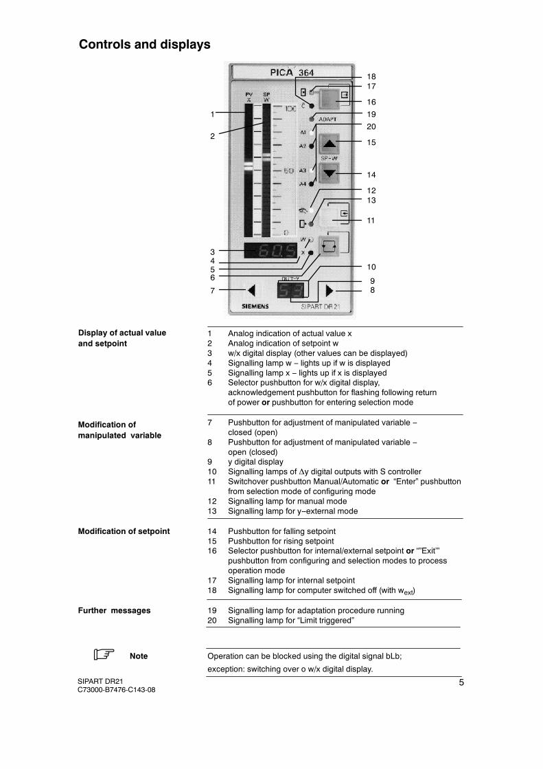
1 Analog indication of actual value x2 Analog indication of setpoint w3 w/x digital display (other values can be displayed)4 Signalling lamp w -- lights up if w is displayed5 Signalling lamp x -- lights up if x is displayed6 Selector pushbutton for w/x digital display,
acknowledgement pushbutton for flashing following returnof power or pushbutton for entering selection mode
7 Pushbutton for adjustment of manipulated variable --closed (open)
8 Pushbutton for adjustment of manipulated variable --open (closed)
9 y digital display10 Signalling lamps of Δy digital outputs with S controller11 Switchover pushbutton Manual/Automatic or “Enter” pushbutton
from selection mode of configuring mode12 Signalling lamp for manual mode13 Signalling lamp for y--external mode
Modification of setpoint 14 Pushbutton for falling setpoint15 Pushbutton for rising setpoint16 Selector pushbutton for internal/external setpoint or “”Exit’”
pushbutton from configuring and selection modes to processoperation mode
17 Signalling lamp for internal setpoint18 Signalling lamp for computer switched off (with wext)
Further messages 19 Signalling lamp for adaptation procedure running20 Signalling lamp for “Limit triggered”
. Note Operation can be blocked using the digital signal bLb;
exception: switching over o w/x digital display.
Display of actual valueand setpoint
Modification ofmanipulated variable
SIPART DR21C73000-B7476-C143-08
5
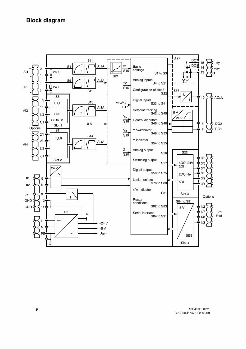
Block diagram
10
AI4A
S13
AI3A
t
S11
AI1A
S6
2
1
4
3
t
AI3
Slot 1
S7
Slot 2
I,U,R
I,U,R
AI4
Options0 %
YNS18
DI1
DI2
24 V
5 V
L+
GND
GND
N
L
M
+24 V
+5 VUREF
S14
t
S21
S57 DO7
DO8
24 V
5 VI
U
I
S56
151413
8
7
S22ZS20
YRS19
wEA/x3S17
x2S16
x1S15
4DO 24V2DI
2DO Rel
5DI
Slot 3
S84 to S91
4/2
4/7
4/8
4/3
Slot 4
SES
5 V
DO2
DO1
+Δy
--Δy
AO/Jy
I Options
TxdRxd
S3
=
1/4
1/3
1/2
1/1
2/4
2/3
2/2
2/1
5
6
12
11
9
PE
3/6
3/5
3/43/3
3/2
3/1
∽
AI1--
+
AI2
UNI
S8 to S10
t
S12
AI2A
S4
S5
249
249
--
+
Basicsettings
S1 to S3
Analog inputsS4 to S21
Configuration of slot 3S22
Digital inputsS23 to S41
Setpoint trackingS42 to S45
Control algorithmS46 to S48
Y switchoverS49 to S53
Y indicatorS54 to S55
Analog outputS56
Switching outputS57
Digital outputsS58 to S75
Limit monitorsS76 to S80
x/w indicatorS81
Restartconditions
S82 to S83
Serial interfaceS84 to S91
L
SIPART DR21C73000-B7476-C143-08
6
Manual Contents
SIPART DR21C73000-B7476-C143-08
7
Contentspage
1 General Part -- Fundamental control technology terms 9. . . . . . . . . . . . . . . . . . . .
2 Technical Description 17. . . . . . . . . . . . . . . . . . . . . . . . . . . . . . . . . . . . . . . . . . . . . . . . . . .2.1 Safety notes and scope of delivery 17. . . . . . . . . . . . . . . . . . . . . . . . . . . . . . . . . . . . . . . . . . . . . . . . . .2.2 Range of Application 18. . . . . . . . . . . . . . . . . . . . . . . . . . . . . . . . . . . . . . . . . . . . . . . . . . . . . . . . . . . . . .2.3 Features 19. . . . . . . . . . . . . . . . . . . . . . . . . . . . . . . . . . . . . . . . . . . . . . . . . . . . . . . . . . . . . . . . . . . . . . . .2.4 Design 24. . . . . . . . . . . . . . . . . . . . . . . . . . . . . . . . . . . . . . . . . . . . . . . . . . . . . . . . . . . . . . . . . . . . . . . . . .2.5 Function principle 26. . . . . . . . . . . . . . . . . . . . . . . . . . . . . . . . . . . . . . . . . . . . . . . . . . . . . . . . . . . . . . . .
2.5.1 Standard controller 26. . . . . . . . . . . . . . . . . . . . . . . . . . . . . . . . . . . . . . . . . . . . . . . . . . . . . . . . . . . . . . . . .2.5.2 Option module 28. . . . . . . . . . . . . . . . . . . . . . . . . . . . . . . . . . . . . . . . . . . . . . . . . . . . . . . . . . . . . . . . . . . .
2.6 Technical Data 34. . . . . . . . . . . . . . . . . . . . . . . . . . . . . . . . . . . . . . . . . . . . . . . . . . . . . . . . . . . . . . . . . . .2.6.1 General data 34. . . . . . . . . . . . . . . . . . . . . . . . . . . . . . . . . . . . . . . . . . . . . . . . . . . . . . . . . . . . . . . . . . . . . .2.6.2 Standard controller 36. . . . . . . . . . . . . . . . . . . . . . . . . . . . . . . . . . . . . . . . . . . . . . . . . . . . . . . . . . . . . . . . .2.6.3 Option module 40. . . . . . . . . . . . . . . . . . . . . . . . . . . . . . . . . . . . . . . . . . . . . . . . . . . . . . . . . . . . . . . . . . . .
3 Functional description of the structure switches 47. . . . . . . . . . . . . . . . . . . . . . . . . .3.1 General 47. . . . . . . . . . . . . . . . . . . . . . . . . . . . . . . . . . . . . . . . . . . . . . . . . . . . . . . . . . . . . . . . . . . . . . . . .3.2 Analog input signal processing (S3 to S21) 47. . . . . . . . . . . . . . . . . . . . . . . . . . . . . . . . . . . . . . . . . .3.3 Digital input signal processing (S23 to S41) 50. . . . . . . . . . . . . . . . . . . . . . . . . . . . . . . . . . . . . . . . . .3.4 Controller types (S1, S42 to S45) 55. . . . . . . . . . . . . . . . . . . . . . . . . . . . . . . . . . . . . . . . . . . . . . . . . . .
3.4.1 General, recurrent functions 55. . . . . . . . . . . . . . . . . . . . . . . . . . . . . . . . . . . . . . . . . . . . . . . . . . . . . . . . .3.4.2 Fixed setpoint controller with 2 independent setpoints (S1 = 0) 59. . . . . . . . . . . . . . . . . . . . . . . . . . . .3.4.3 Slave controller, synchronized controller, SPC-controller 62. . . . . . . . . . . . . . . . . . . . . . . . . . . . . . . . .3.4.4 DDC-Fixed setpoint controller (S1 = 2) 68. . . . . . . . . . . . . . . . . . . . . . . . . . . . . . . . . . . . . . . . . . . . . . . .3.4.5 Controlled ratio controller (S1 = 3) 75. . . . . . . . . . . . . . . . . . . . . . . . . . . . . . . . . . . . . . . . . . . . . . . . . . . .3.4.6 Control unit/process display (S1 = 4) 80. . . . . . . . . . . . . . . . . . . . . . . . . . . . . . . . . . . . . . . . . . . . . . . . . .3.4.7 Fixed setpoint controller with one setpoint (control system coupling) 89. . . . . . . . . . . . . . . . . . . . . . .3.4.8 Slave controller without Int/Ext -switching (control system coupling) 90. . . . . . . . . . . . . . . . . . . . . . . .
3.5 Control algorithm 91. . . . . . . . . . . . . . . . . . . . . . . . . . . . . . . . . . . . . . . . . . . . . . . . . . . . . . . . . . . . . . . . .3.6 Controller output structures (S2, S49 to S55) 94. . . . . . . . . . . . . . . . . . . . . . . . . . . . . . . . . . . . . . . . .3.7 Analog output signal processing (S56) 110. . . . . . . . . . . . . . . . . . . . . . . . . . . . . . . . . . . . . . . . . . . . . . .3.8 Digital output signal processing (S57 to S75) 111. . . . . . . . . . . . . . . . . . . . . . . . . . . . . . . . . . . . . . . . .3.9 Adaptation (S48) 113. . . . . . . . . . . . . . . . . . . . . . . . . . . . . . . . . . . . . . . . . . . . . . . . . . . . . . . . . . . . . . . . .3.10 Other functions of the standard controller 115. . . . . . . . . . . . . . . . . . . . . . . . . . . . . . . . . . . . . . . . . . . .
3.10.1 Adaptive filter 115. . . . . . . . . . . . . . . . . . . . . . . . . . . . . . . . . . . . . . . . . . . . . . . . . . . . . . . . . . . . . . . . . . . . .3.10.2 Response threshold AH 116. . . . . . . . . . . . . . . . . . . . . . . . . . . . . . . . . . . . . . . . . . . . . . . . . . . . . . . . . . . .3.10.3 Limit value alarm (S76 to S80) 117. . . . . . . . . . . . . . . . . . . . . . . . . . . . . . . . . . . . . . . . . . . . . . . . . . . . . . .3.10.4 Linearizer (S21, oFPA) 118. . . . . . . . . . . . . . . . . . . . . . . . . . . . . . . . . . . . . . . . . . . . . . . . . . . . . . . . . . . . .3.10.5 Restart conditions (S82, S83) 120. . . . . . . . . . . . . . . . . . . . . . . . . . . . . . . . . . . . . . . . . . . . . . . . . . . . . . . .3.10.6 Serial interface and PROFIBUS-DP (S84 to S91) 120. . . . . . . . . . . . . . . . . . . . . . . . . . . . . . . . . . . . . . .
4 Installation 121. . . . . . . . . . . . . . . . . . . . . . . . . . . . . . . . . . . . . . . . . . . . . . . . . . . . . . . . . . . . .4.1 Mechanical Installation 121. . . . . . . . . . . . . . . . . . . . . . . . . . . . . . . . . . . . . . . . . . . . . . . . . . . . . . . . . . . .
4.1.1 Work prior to installation 121. . . . . . . . . . . . . . . . . . . . . . . . . . . . . . . . . . . . . . . . . . . . . . . . . . . . . . . . . . . .4.1.2 Installing the controller 124. . . . . . . . . . . . . . . . . . . . . . . . . . . . . . . . . . . . . . . . . . . . . . . . . . . . . . . . . . . . . .4.1.3 Installation of the options modules 125. . . . . . . . . . . . . . . . . . . . . . . . . . . . . . . . . . . . . . . . . . . . . . . . . . . .
4.2 Electrical Connection 126. . . . . . . . . . . . . . . . . . . . . . . . . . . . . . . . . . . . . . . . . . . . . . . . . . . . . . . . . . . . .4.2.1 Warnings and block diagram 126. . . . . . . . . . . . . . . . . . . . . . . . . . . . . . . . . . . . . . . . . . . . . . . . . . . . . . . . .4.2.2 Connection standard controller 130. . . . . . . . . . . . . . . . . . . . . . . . . . . . . . . . . . . . . . . . . . . . . . . . . . . . . . .4.2.3 Connection of the options modules 133. . . . . . . . . . . . . . . . . . . . . . . . . . . . . . . . . . . . . . . . . . . . . . . . . . .4.2.3.1 Modules for analog measuring inputs 133. . . . . . . . . . . . . . . . . . . . . . . . . . . . . . . . . . . . . . . . . . . . . . . . .4.2.3.2 Connection examples for analog measuring inputs with the module 6DR2800-8J 137. . . . . . . . . . . . .4.2.3.3 Modules for expanding the digital inputs and digital outputs 142. . . . . . . . . . . . . . . . . . . . . . . . . . . . . . .4.2.4 Connection of the interface module 6DR2803-8C 144. . . . . . . . . . . . . . . . . . . . . . . . . . . . . . . . . . . . . . .4.2.4.1 RS 232 point-to-point (END/END) 144. . . . . . . . . . . . . . . . . . . . . . . . . . . . . . . . . . . . . . . . . . . . . . . . . . . .4.2.4.2 RS 485 bus 145. . . . . . . . . . . . . . . . . . . . . . . . . . . . . . . . . . . . . . . . . . . . . . . . . . . . . . . . . . . . . . . . . . . . . . .4.2.4.3 PROFIBUS-DP, 6DR2803-8P 146. . . . . . . . . . . . . . . . . . . . . . . . . . . . . . . . . . . . . . . . . . . . . . . . . . . . . . . .
ManualContents
8 SIPART DR21C73000-B7476-C143-08
5 Operation 149. . . . . . . . . . . . . . . . . . . . . . . . . . . . . . . . . . . . . . . . . . . . . . . . . . . . . . . . . . . . . .5.1 General 149. . . . . . . . . . . . . . . . . . . . . . . . . . . . . . . . . . . . . . . . . . . . . . . . . . . . . . . . . . . . . . . . . . . . . . . . .5.2 Process operation mode 150. . . . . . . . . . . . . . . . . . . . . . . . . . . . . . . . . . . . . . . . . . . . . . . . . . . . . . . . . .5.3 Selection mode 152. . . . . . . . . . . . . . . . . . . . . . . . . . . . . . . . . . . . . . . . . . . . . . . . . . . . . . . . . . . . . . . . . .5.4 Configuration modes 154. . . . . . . . . . . . . . . . . . . . . . . . . . . . . . . . . . . . . . . . . . . . . . . . . . . . . . . . . . . . . .
5.4.1 General, Online and Offline modes 154. . . . . . . . . . . . . . . . . . . . . . . . . . . . . . . . . . . . . . . . . . . . . . . . . . .5.4.2 Configuration mode online-parameters onPA 155. . . . . . . . . . . . . . . . . . . . . . . . . . . . . . . . . . . . . . . . . .5.4.3 Configuration mode adaptation AdAP 156. . . . . . . . . . . . . . . . . . . . . . . . . . . . . . . . . . . . . . . . . . . . . . . .5.4.4 Configuration level offline parameters oFPA 163. . . . . . . . . . . . . . . . . . . . . . . . . . . . . . . . . . . . . . . . . . .5.4.5 Configuration mode structure switch StrS 165. . . . . . . . . . . . . . . . . . . . . . . . . . . . . . . . . . . . . . . . . . . . .5.4.6 Set UNI-module CAE3 173. . . . . . . . . . . . . . . . . . . . . . . . . . . . . . . . . . . . . . . . . . . . . . . . . . . . . . . . . . . .5.4.6.1 Measuring range for mV (S8 = 0) 175. . . . . . . . . . . . . . . . . . . . . . . . . . . . . . . . . . . . . . . . . . . . . . . . . . . . .5.4.6.2 Measuring range for U, I (S8 = 0) 175. . . . . . . . . . . . . . . . . . . . . . . . . . . . . . . . . . . . . . . . . . . . . . . . . . . . .5.4.6.3 Measuring range for thermocouple with internal reference point (S8 = 1) 175. . . . . . . . . . . . . . . . . . . .5.4.6.4 Measuring range for thermocouple with external reference point (S8 = 2) 176. . . . . . . . . . . . . . . . . . . .5.4.6.5 Measuring range for PT100 four-wire and three-wire connection (S8 = 3,4) 176. . . . . . . . . . . . . . . . . .5.4.6.6 Measuring range for PT100 two-wire connection (S8 = 5) 177. . . . . . . . . . . . . . . . . . . . . . . . . . . . . . . . .5.4.6.7 Measuring range for resistance potentiometer (S8 = 6, 7) 177. . . . . . . . . . . . . . . . . . . . . . . . . . . . . . . . .5.4.7 APSt (All Preset) Reset to factory setting 178. . . . . . . . . . . . . . . . . . . . . . . . . . . . . . . . . . . . . . . . . . . . . .
5.5 CPU self-diagnostics 179. . . . . . . . . . . . . . . . . . . . . . . . . . . . . . . . . . . . . . . . . . . . . . . . . . . . . . . . . . . . . .
6 Commissioning 181. . . . . . . . . . . . . . . . . . . . . . . . . . . . . . . . . . . . . . . . . . . . . . . . . . . . . . . .6.1 Adapting the direction of control action to the controlled system 181. . . . . . . . . . . . . . . . . . . . . . . . .6.2 Setting of actuating time in K-controllers (S2 = 0) 183. . . . . . . . . . . . . . . . . . . . . . . . . . . . . . . . . . . . . .6.3 Adaptation of the S-controller to the actuating drive 183. . . . . . . . . . . . . . . . . . . . . . . . . . . . . . . . . . . .6.4 Setting the filter and the response threshold 185. . . . . . . . . . . . . . . . . . . . . . . . . . . . . . . . . . . . . . . . . .6.5 Automatic setting of control parameters by the adaptation method 186. . . . . . . . . . . . . . . . . . . . . . .6.6 Manual setting of the control parameters without knowledge of the plant behavior 189. . . . . . . . . .6.7 Manual setting of the control parameters after the transient function 191. . . . . . . . . . . . . . . . . . . . . .
7 Application examples for configuring the controller 193. . . . . . . . . . . . . . . . . . . . . . .7.1 General 193. . . . . . . . . . . . . . . . . . . . . . . . . . . . . . . . . . . . . . . . . . . . . . . . . . . . . . . . . . . . . . . . . . . . . . . . .7.2 Working with different setpoints 195. . . . . . . . . . . . . . . . . . . . . . . . . . . . . . . . . . . . . . . . . . . . . . . . . . . . .7.3 Configuration examples 199. . . . . . . . . . . . . . . . . . . . . . . . . . . . . . . . . . . . . . . . . . . . . . . . . . . . . . . . . . .7.4 Configuring tool, forms 216. . . . . . . . . . . . . . . . . . . . . . . . . . . . . . . . . . . . . . . . . . . . . . . . . . . . . . . . . . . .
8 Maintenance 223. . . . . . . . . . . . . . . . . . . . . . . . . . . . . . . . . . . . . . . . . . . . . . . . . . . . . . . . . . .8.1 General information and handling 223. . . . . . . . . . . . . . . . . . . . . . . . . . . . . . . . . . . . . . . . . . . . . . . . . . .8.2 Exchanging components 224. . . . . . . . . . . . . . . . . . . . . . . . . . . . . . . . . . . . . . . . . . . . . . . . . . . . . . . . . .8.3 LED-test and software version 226. . . . . . . . . . . . . . . . . . . . . . . . . . . . . . . . . . . . . . . . . . . . . . . . . . . . . .8.4 Spare parts list 227. . . . . . . . . . . . . . . . . . . . . . . . . . . . . . . . . . . . . . . . . . . . . . . . . . . . . . . . . . . . . . . . . . .8.5 Ordering data 228. . . . . . . . . . . . . . . . . . . . . . . . . . . . . . . . . . . . . . . . . . . . . . . . . . . . . . . . . . . . . . . . . . . .
9 General explanation of abbreviations for SIPART DR 229. . . . . . . . . . . . . . . . . . . . . .
Index 235. . . . . . . . . . . . . . . . . . . . . . . . . . . . . . . . . . . . . . . . . . . . . . . . . . . . . . . . . . . . . . . . . . . . . . . .

1 HL1Manual
SIPART DR21C73000-B7476-C143-08
9
1 General Part -- Fundamental control technology terms
D Control loop
The function of a closed-loop control is to bring the output variable x of a controlled systemto a predefined value and to retain this value even under the influence of disturbancevariables z. The controlled variable x is compared with the command variable w. Theresulting system deviation xd = w -- x is processed in the controller to the manipulatedvariable y which acts on the controlled system.
The controlled variable x is measured cyclically in a digital control.
w Command variablex Controlled variablexd System deviationy Manipulated variablez Disturbance variable
1 Controlled system2 Control equipment
z1 z2 z3
1
2yx
xdw -
+
Figure 1-1 Function diagram of control loop
D Sensors and transmitters
The controlled variable can be any physical variable. Frequently controlled variables in pro-cess engineering are pressure, temperature, level and flow.
In most process engineering applications, the process variables are measured using sensorsand transmitters with a standardized signal output (0 to 20 mA or 4 to 20 mA). The standard-ized signal can be connected to several process process devices (loop between e.g. re-corder/indicator/controller). Temperature sensors such as resistance thermometers or ther-mocouples, as well as resistance transmitters, can be connected directly to the controllerusing appropriate input cards (options).
D Final control elements and actuators
In process engineering applications, the manipulated variale y primarily acts on the con-trolled system via a valve, a butterfly valve or another mechanical means of adjustment.Three types of drive are possible for actuating such final control elements:
- Pneumatic actuators with compressed air as the auxiliary energy and electropneumaticsignal converters or electropneumatic positioners. These have a proportional action andare driven by continuous controllers.
- Electric actuators, consisting of an electric motor and gear unit. These have an integralaction and are driven by three-position step controllers. Electric actuators are also poss-ible with an integrated (series-connected) positioner and then have a proportional actionand can be driven by continuous controllers.
1 General Part -- Fundamental control technology terms Manual
10 SIPART DR21C73000-B7476-C143-08
- Hydraulic actuators with electric oil pump and electrohydraulic positioner. These have aproportional action and are also driven by continuous controllers.These types of actuators can be used to implement continuous controls.
- Temperature control loops with diret electric or gas heating and/or cooling systems aredriven by two-postion controllers (on/off controllers). The two-position controllers with theheating or cooling medium via relays, external contactors or thyristor controllers. The ma-nipulated variable y is the on/off ratio. These are referred to as discontinuous controls.
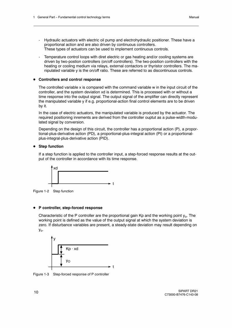
D Controllers and control response
The controlled variable x is compared with the command variable w in the input circuit of thecontroller, and the system deviation xd is determined. This is processed with or without atime response into the output signal. The output signal of the amplifier can directly representthe manipulated variable y if e.g. proportional-action final control elements are to be drivenby it.
In the case of electric actuators, the manipulated variable is produced by the actuator. Therequired positioning inrements are derived from the controller ouptut as a pulse-width-modu-lated signal by conversion.
Depending on the design of this circuit, the controller has a proportional action (P), a propor-tional-plus-derivative action (PD), a proportional-plus-integral action (PI) or a proportional-plus-integral-plus-derivative action (PID).
D Step function
If a step function is applied to the controller input, a step-forced response results at the out-put of the controller in accordance with its time response.
xd
t
Figure 1-2 Step function
D P controller, step-forced response
Characteristic of the P controller are the proportional gain Kp and the working point yo. Theworking point is defined as the value of the output signal at which the system deviation iszero. If disturbance variables are present, a steady-state deviation may result depending onyo.
y
t
Kp · xd
yO
Figure 1-3 Step-forced response of P controller
1 General Part -- Fundamental control technology termsManual
SIPART DR21C73000-B7476-C143-08
11
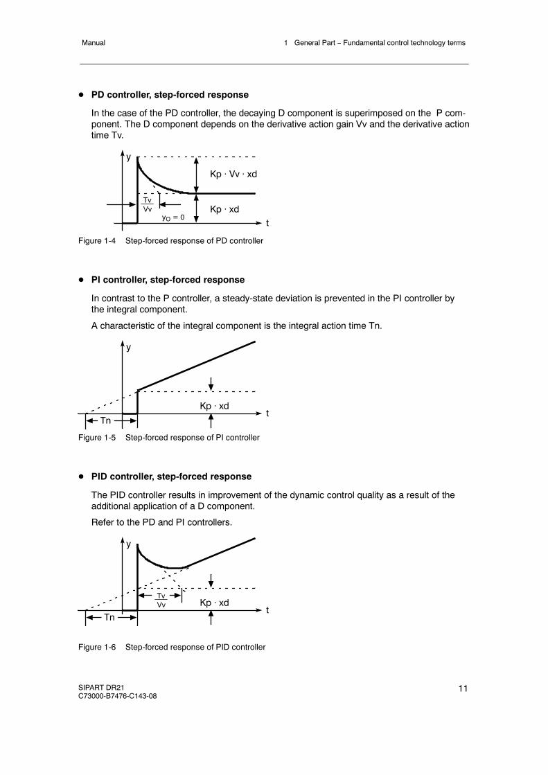
D PD controller, step-forced response
In the case of the PD controller, the decaying D component is superimposed on the P com-ponent. The D component depends on the derivative action gain Vv and the derivative actiontime Tv.
y
t
TvVv
Kp · Vv · xd
Kp · xdyO = 0
Figure 1-4 Step-forced response of PD controller
D PI controller, step-forced response
In contrast to the P controller, a steady-state deviation is prevented in the PI controller bythe integral component.
A characteristic of the integral component is the integral action time Tn.
y
tKp · xd
Tn
Figure 1-5 Step-forced response of PI controller
D PID controller, step-forced response
The PID controller results in improvement of the dynamic control quality as a result of theadditional application of a D component.
Refer to the PD and PI controllers.
y
tKp · xd
Tn
TvVv
Figure 1-6 Step-forced response of PID controller

1 General Part -- Fundamental control technology terms Manual
12 SIPART DR21C73000-B7476-C143-08
D Controller output signal
The controller ouptut signal must be adapted to the final control element. The following mustbe used according to the type of drive/final control element:
Type of drive/actuator Controller output signal
Electric actuators Three-position step controllers
Pneumatic and hydraulic actuators Continuous controllers
Direct heaters/coolers Two-position controllers
D Three-position step controller with internal feedback
The three-position step controller switches the electric motor of the actuator to clockwise,stop or counterclockwise by means of relays or semiconductor switches. The rate of adjust-ment of the actuator can be influenced using different switch-on/pause ratios.
w Command variablex Controlled variablexd System deviationy Manipulated variable
1 Transmitter2 Stepoint adjuster3 Three-position switch4 Feedback with time
response5 Control amplifier6 Actuator
2M
wxd
53
4
L1
N
1x
6
y
0 to 20mA(4 to 20mA)
Figure 1-7 Function diagram of three-position step controller
The output response to the three-position amplifier in conjunction with the integral-actionactuator permits a “continuous” manipulated variable taking into account the responsethreshold.
1 General Part -- Fundamental control technology termsManual
SIPART DR21C73000-B7476-C143-08
13
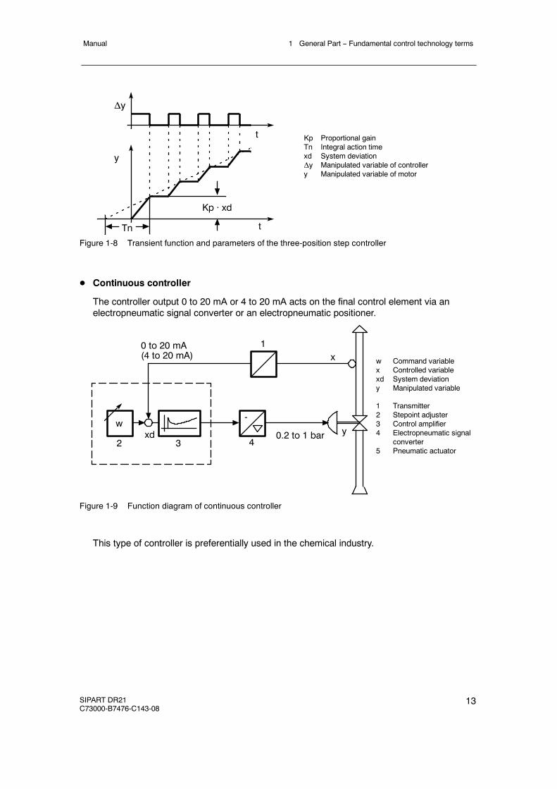
Kp Proportional gainTn Integral action timexd System deviationΔy Manipulated variable of controllery Manipulated variable of motor
Tn
Kp · xd
y
Δy
t
t
Figure 1-8 Transient function and parameters of the three-position step controller
D Continuous controller
The controller output 0 to 20 mA or 4 to 20 mA acts on the final control element via anelectropneumatic signal converter or an electropneumatic positioner.
2
wxd
3
1x
y-
4
0 to 20 mA(4 to 20 mA)
0.2 to 1 bar
w Command variablex Controlled variablexd System deviationy Manipulated variable
1 Transmitter2 Stepoint adjuster3 Control amplifier4 Electropneumatic signal
converter5 Pneumatic actuator
Figure 1-9 Function diagram of continuous controller
This type of controller is preferentially used in the chemical industry.
1 General Part -- Fundamental control technology terms Manual
14 SIPART DR21C73000-B7476-C143-08
D Two-position controller
The two-position controller (or three-position controller for heating/cooling) is used to activaterelays, contactors or thyristor switches for electric heating or cooling.
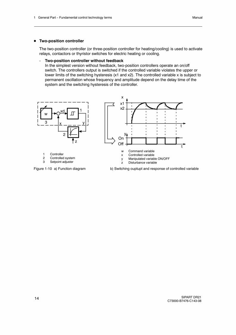
- Two-position controller without feedbackIn the simplest version without feedback, two-position controllers operate an on/offswitch. The controllers output is switched if the controlled variable violates the upper orlower limits of the switching hysteresis (x1 and x2). The controlled variable x is subject topermanent oscillation whose frequency and amplitude depend on the delay time of thesystem and the switching hysteresis of the controller.
1 Controller2 Controlled system3 Setpoint adjuster
3
wxd 1
y
2
x
zt
t
x
y
x1x2
w Command variablex Controlled variabley Manipulated variable ON/OFFz Disturbance variable
OnOff
Figure 1-10 a) Function diagram b) Switching ouptupt and response of controlled variable
1 General Part -- Fundamental control technology termsManual
SIPART DR21C73000-B7476-C143-08
15
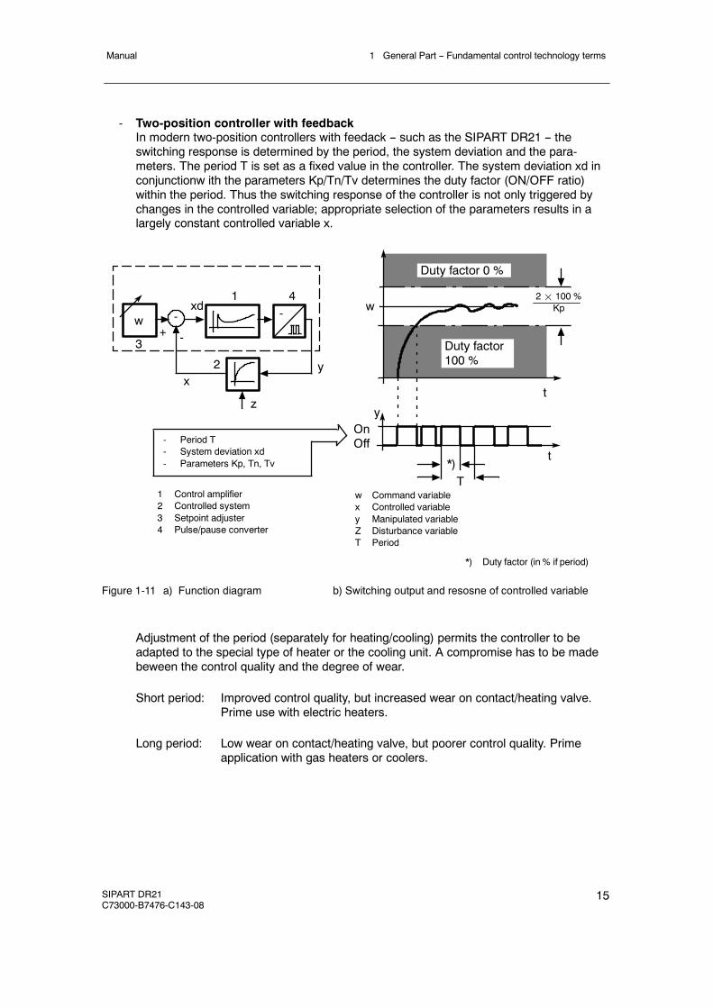
- Two-position controller with feedbackIn modern two-position controllers with feedack -- such as the SIPART DR21 -- theswitching response is determined by the period, the system deviation and the para-meters. The period T is set as a fixed value in the controller. The system deviation xd inconjunctionw ith the parameters Kp/Tn/Tv determines the duty factor (ON/OFF ratio)within the period. Thus the switching response of the controller is not only triggered bychanges in the controlled variable; appropriate selection of the parameters results in alargely constant controlled variable x.
1 Control amplifier2 Controlled system3 Setpoint adjuster4 Pulse/pause converter
3
wxd
1
y2x
z
t
t
yOnOff
-
-+-
4
*)T
w
Duty factor 0 %
Duty factor100 %
2¢ 100 %Kp
- Period T- System deviation xd- Parameters Kp, Tn, Tv
w Command variablex Controlled variabley Manipulated variableZ Disturbance variableT Period
*) Duty factor (in % if period)
Figure 1-11 a) Function diagram b) Switching output and resosne of controlled variable
Adjustment of the period (separately for heating/cooling) permits the controller to beadapted to the special type of heater or the cooling unit. A compromise has to be madebeween the control quality and the degree of wear.
Short period: Improved control quality, but increased wear on contact/heating valve.Prime use with electric heaters.
Long period: Low wear on contact/heating valve, but poorer control quality. Primeapplication with gas heaters or coolers.

1 General Part -- Fundamental control technology terms Manual
16 SIPART DR21C73000-B7476-C143-08
2 Technical Description2.1 Safety notes and scope of delivery
Manual
SIPART DR21C73000-B7476-C143-08
17
2 Technical Description
2.1 Safety notes and scope of delivery
! WARNING
When operating electrical equipment, certain parts of this equipment automati-cally carry dangerous voltages. Failure to observe these instructions couldtherefore lead to serious injury or material damage. Only properly trained andqualified personnel are allowed towork on this equipment. This personnelmustbe fully conversant with all the warnings and commissioning measures as de-scribed in this user’s guide.The perfect and safe operation of this equipment is conditional upon propertransport, proper storage, installation and assembly as well as on careful oper-ation and commissioning.
D Scope of delivery
When the controller is delivered the box also contains:
1 Controller as ordered1 three-pin plug at 115/230 V AC or special plug at 24 V UC2 Clamps, pluggable2 Adhesive labels ”Power supply 115 V” (for 115/230 V-version).1 CD ROM with documentation
D Standard controllers
The following variants of the SIPART DR21 are available:
Order number: Output stage Power Supply
6DR2100-4 K/S-output 24 V UC6DR2100-5 K/S-output 115/230 V AC, switchable
D Options modules (signal converters)
Signal converters have separate ordering- and delivery items.For handling reasons standard controllers and signal converters which were ordered at thesame time may be delivered by separate mail.
D Documentation
This user’s guide is available in the following languages:English C73000-B7476-C143German C73000-B7400-C143
2 Technical Description2.2 Range of Application
Manual
18 SIPART DR21C73000-B7476-C143-08
D Subject to modifications
The user’s guide has been compiled with great care. However, it may be necessary, withinthe scope of product care, to make changes to the product and its operation without priornotice which are not contained in this user’s guide. We are not liable for any costs ensuingfor this reason.
2.2 Range of Application
D Application
The SIPART DR21 process controller is a digital instrument of the mid to upper performanceclass. It is used in control systems in process engineering for instance in the chemical andpetrochemical industries, control- and power station engineering and in other fields of in-dustry such as the food- and drink and tobacco industries.
The controller’s great flexibility makes it suitable for use in simple or intermeshed control cir-cuits. The wide setting range of the control parameters allow the SIPART DR21 to be usedin process engineering both for fast (e.g. flow) and slow controlled systems (e.g. tempera-ture). The controller determines the optimum control parameters independently on requestwithout the user being expected to have any prior knowledge of how the control loop mayrespond. The applied adaptation procedure is suitable for systems with compensation andaperiodic transient behavior; Even greater dead times are taken into account. (Systems with-out compensation cannot be adapted by this method.)
D Controlling tasks
The input structure of the SIPART DR21 controller can be changed by configuring in such away that the following controlling tasks can be solved.
- Fixed value controls, even with disturbance variables applied at the input- Three-component controls- Control circuits with up to two internal setpoints- Follow-up-/synchronization controls- Disturbance variables applied at the output- Computer-controlled circuits in SPC- or DDC-operation- Ratio controls with fixed or manipulated variables
SIPART DR21 can also be configured as a control unit, manual control unit, process displayor resolver transmitter.
The SIPART DR21 controller can be used as a continuous controller with output 0/4 to20 mA, as a stepper controller with a built-in relay for controlling motorized drives or as atwo-position controller for heating/cooling systems.
Overlaid control functions or status- and alarm messages are possible through digital inputs-and outputs.

2 Technical Description2.3 Features
Manual
SIPART DR21C73000-B7476-C143-08
19
2.3 Features
D General
Up to four signal converters can be added to the already generously andextensively equipped, fullyfunctional standard controller to expand the range of application by plugging them into the slots atthe back of the closed device.
SIPART DR21 offers the following features:
D Analog inputs
Two analog inputs for current 0/4 to 20 mA, without potential isolation
The SIPART DR21 controller can be expanded to a total of 4 analog inputs with signalconverters.
The following signal converters are available:
Use as (on) Possible signal generators
UNI-module
AI3 (slot 1) TC/RTD/R/mV, with adapter plug also mA or V, electri-cally isolated, permissible common mode voltage 50 V.
U/I-module
AI3 (slot 1)AI4 (slot 2)
0/4 to 20 mA, 0/2 to 10 V, 0/0.2 V to 1 VElectronic potential isolation, permissible commonmode voltage 10 V.
R-module
AI3 (slot 1)AI4 (slot 2)
Resistance potentiometer
In addition, the modules from the previous program (thermocouple/mV and Pt100) can beused (see SIPART DR20 user’s guide for wiring).
D Output structure
The SIPART DR21 controller has a y-analog output (manipulated variable) with a currentsignal of 0/4 to 20 mA and a switching output with two built-in relays which are interlocked.The relay lock can be released for a universal digital output. The relays are designed for AC250 V, a spark quenching combination for wiring with contactors is provided.
The SIPART DR21 can be configured to operate as a continuous controller, a stepper con-troller for motorized drives or as a two-position controller.
When used as S-controllers, the analog output can be used for outputting x, w or xd forexample.
2 Technical Description2.3 Features
Manual
20 SIPART DR21C73000-B7476-C143-08
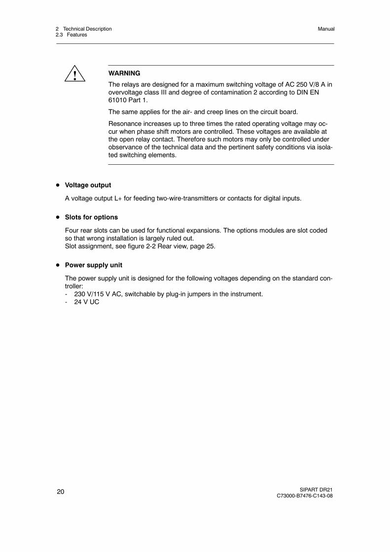
! WARNING
The relays are designed for a maximum switching voltage of AC 250 V/8 A inovervoltage class III and degree of contamination 2 according to DIN EN61010 Part 1.
The same applies for the air- and creep lines on the circuit board.
Resonance increases up to three times the rated operating voltage may oc-cur when phase shift motors are controlled. These voltages are available atthe open relay contact. Therefore such motors may only be controlled underobservance of the technical data and the pertinent safety conditions via isola-ted switching elements.
D Voltage output
A voltage output L+ for feeding two-wire-transmitters or contacts for digital inputs.
D Slots for options
Four rear slots can be used for functional expansions. The options modules are slot codedso that wrong installation is largely ruled out.Slot assignment, see figure 2-2 Rear view, page 25.
D Power supply unit
The power supply unit is designed for the following voltages depending on the standard con-troller:- 230 V/115 V AC, switchable by plug-in jumpers in the instrument.- 24 V UC
2 Technical Description2.3 Features
Manual
SIPART DR21C73000-B7476-C143-08
21
D Digital inputs
Two digital inputs, potential-boundIt can be upgraded to four or seven potential-bound digital inputs with signal converters.The digital inputs can be assigned to the following controller-internal switching signals.
bLb Blocking operationBlocking the entire instrument operation and configuring.Exception: Switching the w/x-digital display
bLS Blocking structuringWith this signal the controller only allows switching to theonline-parameterization levels outside process operation. In this way theparameters for adapting the instrument to the process and the necessarysettings for adaptation can be selected. Structuring is blocked.
bLPS Blocking parameterization and structuringThe entire configuring of the instrument is blocked, this means theparameterization as well. Only the normal process operation according to thepreselected controller type is permitted.
CB Computer-standbyDepending on the controller type, this digital signal together with theInternal/External key causes either switching in the setpoint range. InDDC-controllers, DDC-operation begins.
He Manual externalThis signal blocks the output of the controller and enables direct manualadjustment of the manipulated variable on the front control panel.
N TrackingWith this signal the output of the K-controller and the three-position-stepcontroller with external position feedback is tracked to the tracking signal y N.
Si Safety operationThe output of the K-controller or the three-position-stepper controller withexternal position feedback accepts the parameterized safety value. Inthree-position-stepper controllers with internal position feedback, themanipulated variable runs defined to 0 or 100 %.
P P-operationSwitching from PI (PID) to P (PD)-controller (i.e. switch off the I-part)This function simplifies automatic start-up of control circuits.
tS Switching off the setpoint ramp time
tSH Hold on setpoint change (setpoint ramp)
+yBL / --yBLDirection-dependent blocking of the manipulated variableDirection-dependent limiting of the manipulated variable by external signals,e.g. from the limit switches of the actuating drives. This limiting is effective inevery operating mode.

2 Technical Description2.3 Features
Manual
22 SIPART DR21C73000-B7476-C143-08
D Digital outputs
Two digital outputs, active, potential-bound.It can be upgraded to four or six digital outputs with signal converters.The digital outputs are loadable up to 30 mA per output for direct tripping of relays.The digital outputs can also be used for the variable output, the relay outputs are then freefor any digital signal output.The following controller-internal switching signals can be assigned to the digital outputs orrelays.
RB Computer standbyMessage that the controller can be switched to the external setpoint by theCB-signal.
RC Computer operationMessage that the controller is presently in computer operation or that it hasbeen switched over to the external setpoint by the CB-signal.
H Manual modeMessage that the controller has been switched over to manual mode with theManual/Automatic key.
Nw Tracking operation activeMessage that the controller is in tracking operation.
A1 bis A4 Alarm output Alarm 1 to Alarm 4
MUF group alarm transmitter faultThe instruments’s analog input signals can be monitored for exceeding of themeasuring-range. This signal gives a group alarm if an error is detected.
Δw Output of switching signals for setpoint adjustmentThis function is only active when the controller is structured as a control unit(S1=4).
Δy Output of the incremental y-adjustmentAssignment is only possible on DO1, 2, 7 or 8 (S57).
The following signal converters are available for extending the digital inputs and outputs:
Use on Description
4 x DO/2 x DI Slot 3 4 binary outputs 24 V2 binary inputs 24 V
5 x DI Slot 3 5 binary inputs 24 V
2 x relays Slot 3 2 relay outputs 35 V
D Serial interface
An interface can be retrofitted with signal converters for RS 232/RS 485 or PROFIBUS DP.
2 Technical Description2.3 Features
Manual
SIPART DR21C73000-B7476-C143-08
23
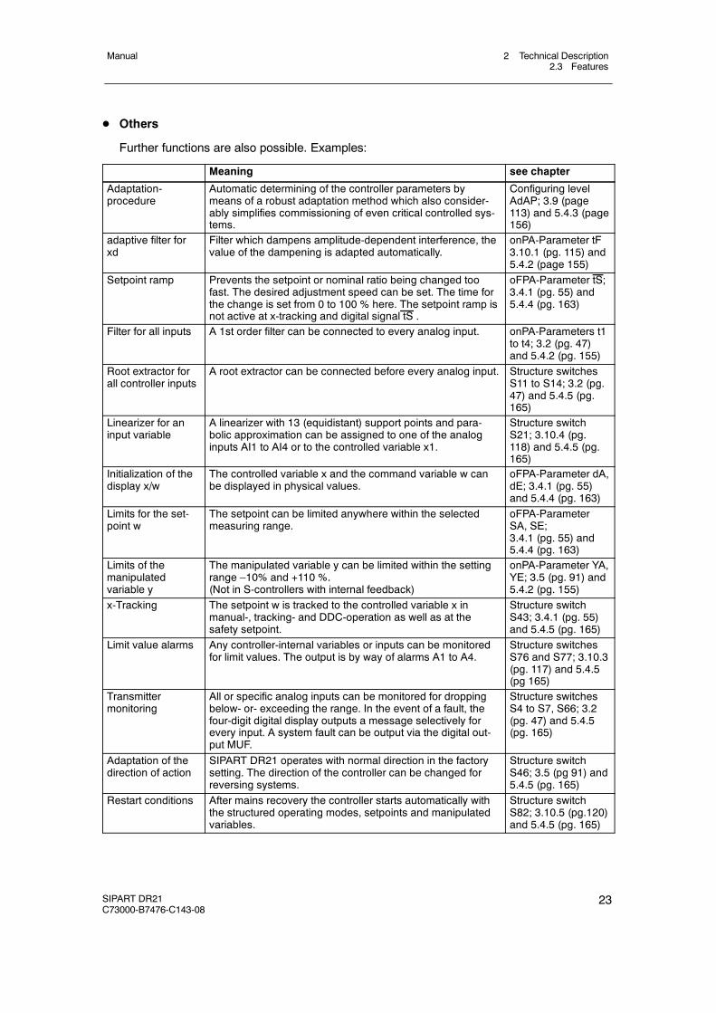
D Others
Further functions are also possible. Examples:
Meaning see chapter
Adaptation-procedure
Automatic determining of the controller parameters bymeans of a robust adaptation method which also consider-ably simplifies commissioning of even critical controlled sys-tems.
Configuring levelAdAP; 3.9 (page113) and 5.4.3 (page156)
adaptive filter forxd
Filter which dampens amplitude-dependent interference, thevalue of the dampening is adapted automatically.
onPA-Parameter tF3.10.1 (pg. 115) and5.4.2 (page 155)
Setpoint ramp Prevents the setpoint or nominal ratio being changed toofast. The desired adjustment speed can be set. The time forthe change is set from 0 to 100 % here. The setpoint ramp isnot active at x-tracking and digital signal tS .
oFPA-Parameter tS;3.4.1 (pg. 55) and5.4.4 (pg. 163)
Filter for all inputs A 1st order filter can be connected to every analog input. onPA-Parameters t1to t4; 3.2 (pg. 47)and 5.4.2 (pg. 155)
Root extractor forall controller inputs
A root extractor can be connected before every analog input. Structure switchesS11 to S14; 3.2 (pg.47) and 5.4.5 (pg.165)
Linearizer for aninput variable
A linearizer with 13 (equidistant) support points and para-bolic approximation can be assigned to one of the analoginputs AI1 to AI4 or to the controlled variable x1.
Structure switchS21; 3.10.4 (pg.118) and 5.4.5 (pg.165)
Initialization of thedisplay x/w
The controlled variable x and the command variable w canbe displayed in physical values.
oFPA-Parameter dA,dE; 3.4.1 (pg. 55)and 5.4.4 (pg. 163)
Limits for the set-point w
The setpoint can be limited anywhere within the selectedmeasuring range.
oFPA-ParameterSA, SE;3.4.1 (pg. 55) and5.4.4 (pg. 163)
Limits of themanipulatedvariable y
The manipulated variable y can be limited within the settingrange –10% and +110 %.(Not in S-controllers with internal feedback)
onPA-Parameter YA,YE; 3.5 (pg. 91) and5.4.2 (pg. 155)
x-Tracking The setpoint w is tracked to the controlled variable x inmanual-, tracking- and DDC-operation as well as at thesafety setpoint.
Structure switchS43; 3.4.1 (pg. 55)and 5.4.5 (pg. 165)
Limit value alarms Any controller-internal variables or inputs can be monitoredfor limit values. The output is by way of alarms A1 to A4.
Structure switchesS76 and S77; 3.10.3(pg. 117) and 5.4.5(pg 165)
Transmittermonitoring
All or specific analog inputs can be monitored for droppingbelow- or- exceeding the range. In the event of a fault, thefour-digit digital display outputs a message selectively forevery input. A system fault can be output via the digital out-put MUF.
Structure switchesS4 to S7, S66; 3.2(pg. 47) and 5.4.5(pg. 165)
Adaptation of thedirection of action
SIPART DR21 operates with normal direction in the factorysetting. The direction of the controller can be changed forreversing systems.
Structure switchS46; 3.5 (pg 91) and5.4.5 (pg. 165)
Restart conditions After mains recovery the controller starts automatically withthe structured operating modes, setpoints and manipulatedvariables.
Structure switchS82; 3.10.5 (pg.120)and 5.4.5 (pg. 165)
2 Technical Description2.4 Design
Manual
24 SIPART DR21C73000-B7476-C143-08
2.4 Design
D Standard controller
The process controller has a modular structure and is therefore maintenance friendly andeasy to convert- and retrofit.The standard controller consists of- the front module with the control- and display elements- the backplane module with the power supply unit- the plastic housing with four slots for optional modules
D Front module
The front module accommodates the control- and display elements, the CPU (Central Pro-cessing Unit) and the connectors for the backplane- and options modules.
It is operated by a membrane keyboard with IP64 degree of protection. The front design isbased directly on the SIPART DR 20/22/24-controller-family with color coded assignment ofthe display- and control elements.
For better monitoring of the process, SIPART DR21 has user-friendly analog displays for thesetpoint- and actual value display, a four-digit digital display which can be set for setpoint,actual value and alarms (depending on the controller setting), a two-digit digital display forthe manipulated variable y, numerous control keys and indicator diodes for various statussignals.
The tag plate and the scales for the analog displays are replaceable.
D Backplane module with power supply unit
The following signal connections are accessible through the backplane.- 2 analog inputs AI1, AI2, potential-bound to GND, 0/4 to 20 mA- 1 analog output AO, potential-bound to GND, 0/4 to 20 mA- 2 digital outputs + Δ y,- Δ y, potential-free via relay contacts- 2 digital inputs DI1, DI2, for 24V-logic, function can be set- 2 digital outputs DO1, DO2, for 24V- logic, function and direction can be set- 1 Voltage output L+ to the transmitter supply
The power supply is located in a die-cast housing on the backplane module. The heat loss istransferred to the back of the controller by cooling fins.
A DIN rail can be mounted for connecting a powerful coupling relay module.
The power supply unit is high powered and offers a total 200 mA current for:- supplying the analog output (0/4 to 20 mA)- Active digital outputs (up to 6 digital outputs)- L+-output for supplying two-wire-transmitters- supplying the interface module
2 Technical Description2.4 Design
Manual
SIPART DR21C73000-B7476-C143-08
25
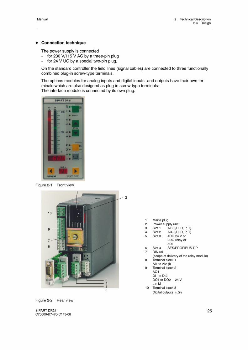
D Connection technique
The power supply is connected- for 230 V/115 V AC by a three-pin plug- for 24 V UC by a special two-pin plug.
On the standard controller the field lines (signal cables) are connected to three functionallycombined plug-in screw-type terminals.
The options modules for analog inputs and digital inputs- and outputs have their own ter-minals which are also designed as plug-in screw-type terminals.The interface module is connected by its own plug.
Figure 2-1 Front view
1 Mains plug2 Power supply unit3 Slot 1 AI3 (I/U, R, P, T)4 Slot 2 AI4 (I/U, R, P, T)5 Slot 3 4DO,24 V or
2DO relay or5DI
6 Slot 4 SES/PROFIBUS-DP7 DIN rail
(scope of delivery of the relay module)8 Terminal block 1
AI1 to AI2 (I)9 Terminal block 2
AO1DI1 to DI2DO1 to DO2 24 VL+; M
10 Terminal block 3Digital outputs±Δy
3456
2
1
10
9
7
8
Figure 2-2 Rear view
2 Technical Description2.5 Function principle
Manual
26 SIPART DR21C73000-B7476-C143-08
2.5 Function principle
2.5.1 Standard controller
D General
The SIPART DR21 controller operates on the basis of a modern, highly-integrated microcon-troller in C-MOS-technology. A large number of functions for controlling processing plantsare stored in the instrument’s ROM. The user can adapt the controller to the task himself byconfiguring it.
D Analog inputs AI1 and AI2.
The analog inputs of the SIPART DR21 are designed for 0/4 to 20 mA input signals. The in-puts have an input load resistance of 248 Ω and are potential-bound. The start value 0 mAor 4 mA is determined by the structure switches S4 and S5.
D Outputs for the manipulated variable Y
The standard controller has the following outputs
K-output: switchable between 0 or 4 to 20 mA, potential-bound (S56)
S-output: two relays, NOC, interlocked in factory setting, built-in spark quenching de-signed for wiring with medium contactors. Other functions can be assignedto the relay outputs by configuration (structure switches S57 to S68), e.g.manipulated variable output±Δy in S-controllers.
D Digital outputs DO1 and DO2
The digital outputs are short-circuit-proof and can drive commercially available relays or theinterface relays 6DR2804-8A/8B directly. Different functions can be assigned to the digitaloutputs by configuration (structure switches S57 to S68).
D Digital inputs DI1 and DI2
The inputs are designed in 24-V-logic and are potential-bound. The function is assigned tothe input by configuration of the controller (structure switches S23 to S33).
D CPU
The microcontroller used has integrated AD- and DA-converters and watchdog-circuits forcycle monitoring. The processor operates with a 64k EPROM (on a socket and thereforereplaceable) and a 1k RAM.
The SIPART DR21 program runs with a fixed cycle time of 100 ms. A process image is gen-erated at the start of every routine. The analog- and digital inputs, the operation of the frontkeyboard and the process variables received by the serial interface are acquired oraccepted. All calculations are made according to the stored functions with these input sig-nals. Then output to the display elements, the analog outputs and the digital outputs and
2 Technical Description2.5 Function principle
Manual
SIPART DR21C73000-B7476-C143-08
27
storage of the calculated variables for transmission mode of the serial interface take place.In S-controllers, the program run is interrupted every 5 ms to be able to switch off the S-out-puts for better resolution. The interface communication also runs in interrupt mode.
D Power supply unit
A cast, overload-protected mains transformer for 115 V or 230 V AC built into a heat sink ora primary clocked plug-in type power supply unit for 24 V UC built into a heat sink generatesthe secondary internal supply voltages +24 V, +5 V and U ref from the power supply. Themetal body rests on protective conductors (protection class I).The power supply and internal supply voltages are isolated from each other by safeseparation.The internal supply voltages are function low voltages.Since no other voltages are generated in the instrument, these statements apply to all fieldsignal lines with the exception of relay connection lines (used standards see chapter 2.6Technical data, page 34).
D Configuring
The controller has a large number of prepared functions for controlling processing plants.The user programs the instrument himself by selecting the desired functions or setting para-meters by setting structure switches. The total functioning of the instrument is given by thecombination of the individual structure switches or parameter settings. No programmingknowledge is necessary (see Operation, chapter 5, page 149).
All settings are made without exception on the front operating panel of the SIPART DR21 orthe serial interface.
The job-specific program written in this way is saved in the non-volatile user program mem-ory.
The instrument is configured as a fixed value controller in the factory setting. This settingcan be restored with the ”APSt”-function at any time.
The following parameterization- and structuring modes are available for configuring theSIPART DR21 controller.
onPA The transmission properties of the controller and with these the process courseare determined with the online-parameters. They can be changed during controloperation (online)
oFPA The offline-parameters determine the basic functions such as display elements,limit values, safety values. The controller is blocked (offline) while they are beingset, the last value of the manipulated variable is held.
StrS The instrument structure, e.g. fixed value controller or follow-up controller is de-termined with the structure switches. The controller is blocked (offline) whilethey are being set, the last value of the manipulated variable is held.
APSt The all preset-function restores the factory setting.
2 Technical Description2.5 Function principle
Manual
28 SIPART DR21C73000-B7476-C143-08
(AdAP) In the adaptation level the output conditions for automatic adaptation of the con-troller parameters to the process is preset and adaptation started.
(CAE3) The measuring range is set and fine adjustment made if necessary here for theUNI-module.The CAE3-menu is only displayed if it has been released in the structuring level(structure switch S6>3).
2.5.2 Option module
The following option modules are described in this chapter
6DR2800-8J I/U-module6DR2800-8R R-module6DR2800-8V UNI-module6DR2805-8A reference point6DR2805-8J measuring range plug6DR2801-8D module with 2 DO (relay)6DR2801-8E module with 2 DI and 4 DO6DR2801-8C module with 5 DI6DR2803-8P serial interface PROFIBUS-DP6DR2803-8C serial interface RS 232/RS 4856DR2804-8A module with 4 DO relays6DR2804-8B module with 2 DO relays
6DR2800-8J I/U-module
D Input variables current 0/4 to 20 mA or voltage 0/0.2 to 1 V or 0/2 to 10 V
The module’s input amplifier is designed as a differentiating amplifier with shuntable gain for0 to 1 V or 0 to 10 V input signal. For current input signals the 49.9 Ω 0.1 % impedance isswitched on by plug-in bridges on the module. The start value 0 mA or 4 mA or 0 V or 0.2 V(2 V) is defined by configuration in the standard controller. The differentiating amplifier is de-signed for common mode voltages up to 10 V and has a high common mode suppression.As a result it is possible to connect the current inputs in series as for electrical isolation whenthey have common ground. For voltage inputs this circuit technique makes it possible to sup-press the voltage drops on the ground conductor by two-pole wiring on potential-bound volt-age sources. We refer to an electronic potential isolation.
6DR2800-8R R-module
D Input for resistance- or current potentiometer
Potentiometers with rated values of 80 Ω to 1200 Ω can be connected as resistance trans-mitters. A constant current of Is = 5 mA is fed to the potentiometer wiper. The wiper resis-tance is therefore not included in the measurement. Resistors are switched parallel to thepotentiometer by settings on the module and a rough range selection made. Start of scaleand -- full scale are set with the two adjusting pots on the back of the module.
2 Technical Description2.5 Function principle
Manual
SIPART DR21C73000-B7476-C143-08
29
This fine adjustment can be made on the displays on the front module (if structured appropri-ately). For adjustment with a remote measuring instrument, the analog output can beassigned to the appropriate input.
The external wiring must be changed for resistance transmitters which cannot withstand the5 mA wiper current or which have a rated resistance >1 kΩ. The constant current is then notfed through the wiper but through the whole resistance network of the potentiometer. A volt-age divider measurement is now made through the wiper. Coarse adjustment is made by aremote parallel resistor to the resistance potentiometer.
This module can also be used as a current input with adjustable range start and full scale.The load is 49.9 Ω and is referenced to ground.
6DR2800-8V UNI-module
D Direct connection of thermocouple- or Pt100-sensors, resistance- or mV-transmitters
Measured value sensors such as thermocouples (TC), resistance thermometers Pt100(RTD), resistance potentiometers (R) or voltage transmitters in the mV-range can be con-nected directly. The measuring variable is selected by configuring the controller in theStrS-level (structure switches S6, S8, S9 and S10), the measuring range and the other para-meters are set in the CAE3-menu. The sensor-specific characteristics (linearization) for ther-mocouples and Pt100-resistance thermometers are stored in the contoller’s program mem-ory and are automatically taken into account. No settings need to be made on the moduleitself.
The signal lines are connected by a plug terminal block with screw-type terminals. Whenusing thermocouples with internal reference point, this terminal block must be replaced bythe terminal 6DR2805-8A. With the measuring range plug 6DR2805-8J in place of the ter-minal block, the measuring range of the direct input (0/20 to 100 mV) can be extended to 0/2up to 10 V or 0/4 up to 20 mA.
The UNI-module operates with an AD-converter with 18 bit resolution. The measuring inputsand ground of the standard controller are electrically isolated with a permissible commonmode voltage of 50 V UC.
The UNI-module can only be used at slot 1 (AI3).
6DR2805-8A Reference point
D Terminal with internal reference point for thermocouples
This terminal is used in connection with the UNI-module for temperature measuring withthermocouples at an internal reference point. It consists of a temperature sensor which ispre-assembled on a terminal block and plated to avoid mechanical damage.
2 Technical Description2.5 Function principle
Manual
30 SIPART DR21C73000-B7476-C143-08
6DR2805-8J Measuring range plug
D Measuring range plug for current 0/4 to 20 mA or voltage 0/2 to 10 V
The measuring range plug is used in connection with the UNI-module to measure current- orvoltage. The input variable is reduced to a signal range of 0/20 to 100 mV by a voltage di-vider or shunt resistors in the measuring range plug.
Wiper resistors with 250 Ω or 50 Ω are available optionally at 2 different terminals for 0/4 to20 mA-signals.
The electrical isolation of the UNI-module is retained even when the measuring range plug isused.
6DR2801-8D 2 DO relays
D Digital output module with 2 relay contacts
To convert 2 digital outputs to relay contacts up to 35 V UC.
This module is equipped with 2 relays whose switching contacts have potential free outputs.The RC-combinations of the spark quenching elements are respectively parallel to the rest-and working contacts.
In AC-consumers with low power the current flowing through the capacitor of the sparkquenching element when the contact is open may interfere (e.g. the hold current of someswitching elements is not exceeded). In this case the capacitors (1 μF) must be removedand replaced with low capacitance capacitors.
The 68 V suppressor diodes parallel to the capacitors act additionally to reduce the inducedvoltage.
CAUTION
The relays used on the digital output module are designed for a maximumrating up to UC 35 V. The same applies for the air- and creep lines on thecircuit board. Higher voltages may therefore only be switched through appro-priately approved series connected circuit elements under observance of thetechnical data and the pertinent safety regulations.
6DR2801-8E 2 DI and 4 DO
D Digital signal module with two digital inputs and 4 digital outputs
The module serves to extend the digital inputs and digital outputs already existing in thestandard controller.
The inputs are designed in 24-V-logic and are potential-bound. The functions are assigned tothe inputs- and outputs by configuration of the controller. (Structure switches S23 to S33,S58 to S68).
The digital outputs are short-circuit-proof and can drive commercially available relays or theinterface relays 6DR2804-8A/8B directly.

2 Technical Description2.5 Function principle
Manual
SIPART DR21C73000-B7476-C143-08
31
6DR2801-8C 5 DI
D Digital input module with 5 digital inputs
The module serves to extend the digital inputs already existing in the standard controller.
The inputs are designed in 24-V-logic and are potential-bound. The function is assigned tothe input by configuration of the controller (structure switches S23 to S33).
6DR2803-8P serial interface PROFIBUS-DP
The 6DR2803-8P module is a PROFIBUS-DP-interface module with RS-485-driver and electri-cal isolation from the instrument. It operates as an intelligent converter module and adapts theprivate SIPART- to the open PROFIBUS-DP-protocol.
This options card can be used in all SIPART-DR-instruments in slot 4. The following settingsmust be made with the appropriate structure switches for the serial interfaces.
- Interface on- Even parity- LRC without- Baud rate 9600- Parameters/process values writable (as desired)- Station number of choice 0 to 125
Make sure that the station number is not assigned double on the bus. The PROFIBUS-moduleserves to connect the SIPART-controllers to a master system for control and monitoring. Inaddition the parameters and structure switches of the controller can be read and written.Up to 32 process variables can be selected and read out cyclically by configuration of thePROFIBUS-module.
The process data are read out of the controller in a polling procedure with an update time<300 ms. If the master write process data to the slave, these become active after a maximumof one controller cycle.
A technical description including the controller-base-file (*.GSD) is available in Internet for creat-ing a master-slave-linking software for interpreting the identifications and useful data from andto the SIPART-controller.Internet address: www.fielddevices.com [Edition: 05.2000])
The SIPART S5 DP and SIPART S7 DP programs are offered for DP-masters SIMATIC S5 andS7.

2 Technical Description2.5 Function principle
Manual
32 SIPART DR21C73000-B7476-C143-08
6DR2803-8C Serial interface RS 232/RS 485
D Serial interface for RS 232 or RS 485 with electrical isolation
Can be used in slot 4, the structure switches S84 to S91 must be set for the transmissionprocedure.
For connecting the controller SIPART DR21 to a master system for control and monitoring.All process variables can be sent, the external setpoint, tracking variable, operating states,parameters and structurings sent and received via the interface.
Interface communication can take place:
RS 232 as a point-to-point connection
SIPART Bus The SIPART bus driver is no longer available.Therefore, please realize multi--couplings via RS 485 or PROFIBUS DP.
RS 485 As a serial data bus with up to 32 users.
The interface module 6DR2803-8C offers electrical isolation between Rxd/Txd and the con-troller. Switching can be performed between RS 232 and RS 485 with a plug-in bridge.
A detailed technical description of the data communication for creating a linking software isavailable in Internet under www.fielddevices.com [Edition 05.2000].
Rxd/Txd B
Rxd/Txd A
24 V
0 V
Txd
Rxd-1
+1
+7.5 V
-7.5 V
+7.5V
-7.5 V
-7.5V
Rxd
Txd2
3
7
8
Other connections: NC
24 V
0 V
Txd
Rxd
Other connections: NC
Rxd/Txd
3
NC2, 7
8
+7.5 V
+7.5 V
+7.5V
SIPARTbus
RS 485
RS 485+150R
RS 232
Figure 2-3 Block diagram serial interface inRS 232/SIPART BUS
Figure 2-4 Block diagram serial interface atInterface RS 485
2 Technical Description2.5 Function principle
Manual
SIPART DR21C73000-B7476-C143-08
33
6DR2804-8A module with 4 DO-relays6DR2804-8B module with 2 DO-relays
D Coupling relay module with 2 or 4 relays
To convert 2 or 4 binary outputs to relay contacts up to 230 V UC.
The relays can be snapped onto a mounting rail on the back of the controller. The mountingrail is delivered with the coupling relay module.
One or two relay modules are installed per version. Each of these modules consists of tworelays with quench diodes parallel to the control winding. Every relay has a switching contactwith spark quenching in both switching branches. In AC-consumers with a very low power,the current flowing (e.g. hold current in contactors) through the spark quenching capacitor(33nF) when the contact is open interferes. In this case they should be replaced by capaci-tors of the same construction type, voltage strength and lower value.
The switching contact is fed to the plug terminals with 3 poles so that the rest and workingcircuits can be switched. The relays can be controlled directly from the controller’s digitaloutputs by external wiring.
!CAUTION
The relays used on the interface relay module are designed for a maximumrating of AC 250 V in overvoltage class III and contamination factor 2 accordingto DIN EN 61010 Part 1.
The same applies for the air- and creep lines on the circuit board.
Resonance increases up to double the rated operating voltage may occur whenphase shift motors are controlled. These voltages are available at the open re-lay contact. Therefore such motors may only be controlled under observance ofthe technical data and the pertinent safety conditions via approved switchingelements.
2 Technical Description2.6 Technical Data
Manual
34 SIPART DR21C73000-B7476-C143-08
2.6 Technical Data
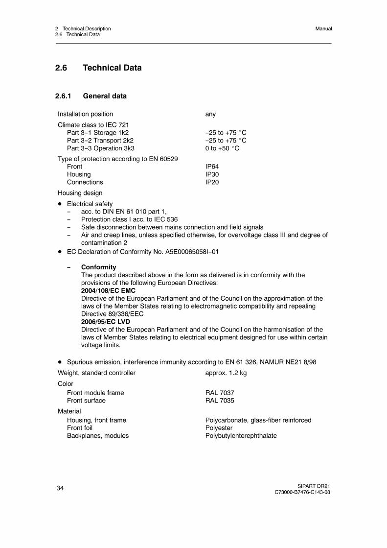
2.6.1 General data
Installation position any
Climate class to IEC 721Part 3--1 Storage 1k2Part 3--2 Transport 2k2Part 3--3 Operation 3k3
--25 to +75 _C--25 to +75 _C0 to +50 _C
Type of protection according to EN 60529FrontHousingConnections
IP64IP30IP20
Housing design
D Electrical safety-- acc. to DIN EN 61 010 part 1,-- Protection class I acc. to IEC 536-- Safe disconnection between mains connection and field signals-- Air and creep lines, unless specified otherwise, for overvoltage class III and degree of
contamination 2D EC Declaration of Conformity No. A5E00065058I--01
-- ConformityThe product described above in the form as delivered is in conformity with theprovisions of the following European Directives:2004/108/EC EMCDirective of the European Parliament and of the Council on the approximation of thelaws of the Member States relating to electromagnetic compatibility and repealingDirective 89/336/EEC2006/95/EC LVDDirective of the European Parliament and of the Council on the harmonisation of thelaws of Member States relating to electrical equipment designed for use within certainvoltage limits.
D Spurious emission, interference immunity according to EN 61 326, NAMUR NE21 8/98
Weight, standard controller approx. 1.2 kg
ColorFront module frameFront surface
RAL 7037RAL 7035
MaterialHousing, front frameFront foilBackplanes, modules
Polycarbonate, glass-fiber reinforcedPolyesterPolybutylenterephthalate
2 Technical Description2.6 Technical Data
Manual
SIPART DR21C73000-B7476-C143-08
35
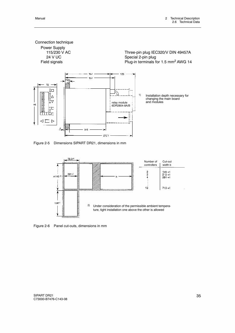
Connection techniquePower Supply
115/230 V AC24 V UC
Field signals
Three-pin plug IEC320/V DIN 49457ASpecial 2-pin plugPlug-in terminals for 1.5 mm2 AWG 14
1) Installation depth necessary forchanging the main boardand modulesrelay module
6DR2804-8A/B
Figure 2-5 Dimensions SIPART DR21, dimensions in mm
Number of Cut-outcontrollers width b
2) Under consideration of the permissible ambient tempera-ture, tight installation one above the other is allowed
Figure 2-6 Panel cut-outs, dimensions in mm
2 Technical Description2.6 Technical Data
Manual
36 SIPART DR21C73000-B7476-C143-08
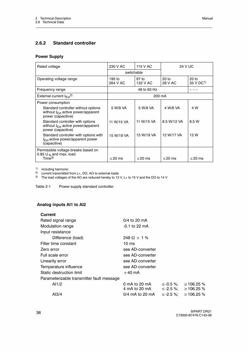
2.6.2 Standard controller
Power Supply
Rated voltage 230 V AC 115 V AC 24 V UCg
switchable
Operating voltage range 195 to264 V AC
97 to132 V AC
20 to28 V AC
20 to35 V DC1)
Frequency range 48 to 63 Hz -- -- --
External current IExt2) 200 mA
Power consumptionStandard controller without optionswithout IExt active power/apparentpower (capacitive)Standard controller with optionswithout IExt active power/apparentpower (capacitive)Standard controller with options withIExt active power/apparent power(capacitive)
5 W/9 VA
11 W/15 VA
15 W/19 VA
5 W/9 VA
11 W/15 VA
15 W/19 VA
4 W/6 VA
8.5 W/12 VA
12 W/17 VA
4 W
8.5 W
12 W
Permissible voltage breaks based on0.85 U N and max. load
Time3) ≤20 ms ≤20 ms ≤20 ms ≤20 ms
1) including harmonic2) current transmitted from L+, DO, AO to external loads3) The load voltages of the AO are reduced hereby to 13 V, L+ to 15 V and the DO to 14 V
Table 2-1 Power supply standard controller
Analog inputs AI1 to AI2
CurrentRated signal range 0/4 to 20 mAModulation range -0.1 to 22 mAInput resistance
Difference (load) 248 Ω± 1 %Filter time constant 10 msZero error see AD-converterFull scale error see AD-converterLinearity error see AD-converterTemperature influence see AD-converterStatic destruction limit ±40 mAParameterizable transmitter fault message
AI1/2 0 mA to 20 mA4 mA to 20 mA
≤-0.5 %;≤-2.5 %;
≥106.25 %≥106.25 %
AI3/4 0/4 mA to 20 mA ≤-2.5 %; ≥106.25 %
2 Technical Description2.6 Technical Data
Manual
SIPART DR21C73000-B7476-C143-08
37
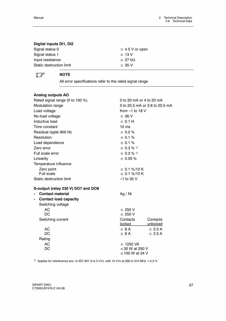
Digital inputs DI1, DI2Signal status 0 ≤ 4.5 V or openSignal status 1 ≥ 13 VInput resistance ≥ 27 kΩStatic destruction limit 35 V
. NOTE
All error specifications refer to the rated signal range
Analog outputs AORated signal range (0 to 100 %) 0 to 20 mA or 4 to 20 mAModulation range 0 to 20.5 mA or 3.8 to 20.5 mALoad voltage from --1 to 18 VNo-load voltage ≤ 26 VInductive load ≤ 0.1 HTime constant 10 msResidual ripple 900 Hz ≤ 0.2 %Resolution ≤ 0.1 %Load dependence ≤ 0.1 %Zero error ≤ 0.3 % 1)
Full scale error ≤ 0.3 % 1)
Linearity ≤ 0.05 %Temperature influence
Zero pointFull scale
≤ 0.1 %/10 K≤ 0.1 %/10 K
Static destruction limit --1 to 35 V
S-output (relay 230 V) DO7 and DO8- Contact material Ag / Ni- Contact load capacity
Switching voltageACDC
≤ 250 V≤ 250 V
Switching current Contacts Contactslocked unlocked
ACDC
≤ 8 A ≤ 2.5 A≤ 8 A ≤ 2.5 A
RatingACDC
≤ 1250 VA≤30 W at 250 V≤100 W at 24 V
1) Applies for interference acc. to IEC 801-3 to 3 V/m, with 10 V/m at 290 to 310 MHz≤4.3 %
2 Technical Description2.6 Technical Data
Manual
38 SIPART DR21C73000-B7476-C143-08
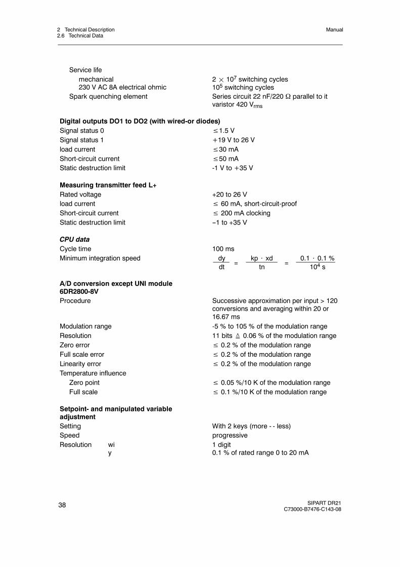
Service lifemechanical230 V AC 8A electrical ohmic
2¢ 107 switching cycles105 switching cycles
Spark quenching element Series circuit 22 nF/220 Ω parallel to itvaristor 420 Vrms
Digital outputs DO1 to DO2 (with wired-or diodes)Signal status 0 ≤1.5 VSignal status 1 +19 V to 26 Vload current ≤30 mAShort-circuit current ≤50 mAStatic destruction limit -1 V to +35 V
Measuring transmitter feed L+Rated voltage +20 to 26 Vload current ≤ 60 mA, short-circuit-proofShort-circuit current ≤ 200 mA clockingStatic destruction limit --1 to +35 V
CPU dataCycle time 100 msMinimum integration speed dy
dtkp ⋅ xd
tn0.1 ⋅ 0.1 %
104 s= =
A/D conversion except UNI module6DR2800-8VProcedure Successive approximation per input > 120
conversions and averaging within 20 or16.67 ms
Modulation range -5 % to 105 % of the modulation rangeResolution 11 bits≙ 0.06 % of the modulation rangeZero error ≤ 0.2 % of the modulation rangeFull scale error ≤ 0.2 % of the modulation rangeLinearity error ≤ 0.2 % of the modulation rangeTemperature influence
Zero point ≤ 0.05 %/10 K of the modulation rangeFull scale ≤ 0.1 %/10 K of the modulation range
Setpoint- and manipulated variableadjustmentSetting With 2 keys (more - - less)Speed progressiveResolution wi
y1 digit0.1 % of rated range 0 to 20 mA
2 Technical Description2.6 Technical Data
Manual
SIPART DR21C73000-B7476-C143-08
39
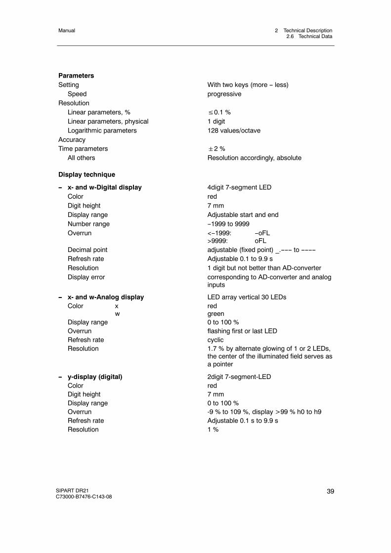
ParametersSetting With two keys (more -- less)
Speed progressiveResolution
Linear parameters, % ≤0.1 %Linear parameters, physical 1 digitLogarithmic parameters 128 values/octave
AccuracyTime parameters 2 %
All others Resolution accordingly, absolute
Display technique
-- x- and w-Digital display 4digit 7-segment LEDColor redDigit height 7 mmDisplay range Adjustable start and endNumber range --1999 to 9999Overrun <--1999: --oFL
>9999: oFLDecimal point adjustable (fixed point) _.------ to --------Refresh rate Adjustable 0.1 to 9.9 sResolution 1 digit but not better than AD-converterDisplay error corresponding to AD-converter and analog
inputs
-- x- and w-Analog display LED array vertical 30 LEDsColor x
wredgreen
Display range 0 to 100 %Overrun flashing first or last LEDRefresh rate cyclicResolution 1.7 % by alternate glowing of 1 or 2 LEDs,
the center of the illuminated field serves asa pointer
-- y-display (digital) 2digit 7-segment-LEDColor redDigit height 7 mmDisplay range 0 to 100 %Overrun -9 % to 109 %, display >99 % h0 to h9Refresh rate Adjustable 0.1 s to 9.9 sResolution 1 %

2 Technical Description2.6 Technical Data
Manual
40 SIPART DR21C73000-B7476-C143-08
2.6.3 Option module
6DR2800-8J/R Analog inputs AI3 (slot 1), AI4 (slot 2)
Signal converter for
Order number:
Current
6DR2800-8J
Voltage
6DR2800-8J
Resistancepotentiometer6DR2800-8R
Range start
Min. span (100 %)Max. zero point suppressionRange full scaleDynamic range
0 or 4 mA 1)
20 mA--4 to 115 %
0 V or 2 V1)
or 199.6 mV 1)
10 V, 998 mV--4 to 115 %
0 Ω
ΔR≥ 0.3 R 3)
RA≤ 0.2 R 3)
1.1 R 3)
--4 to 115 %
Transmitter fault message MUF --2,5 %≥ MUF≥ 106.25 %
Input resistanceDifferenceCommon mode
Permissible common mode voltageSupply currentLine resistance
Three-wire-circuit
49.9 Ω0.1 %500 kΩ0 to +10 V
200 kΩ≥ 200 kΩ0 to +10 V
5 mA5%
per< 10 Ω
Filter time constant 20 % 50 ms 50 ms 50 ms
Error 2)
Zero pointGainLinearityCommon mode
≤ 0.3 %≤ 0.5 %≤ 0.05 %≤ 0.07 %/V
≤ 0.2 %≤ 0.2 %≤ 0.05 %≤ 0.02 %/V
≤ 0.2 %≤ 0.2 %≤ 0.2 %--
Influence of temperature 2)
Zero pointGain
≤ 0.05 %/10 K≤ 0.1 %/10 K
≤ 0.02 %/10 K≤ 0.1 %/10 K
≤ 0.1 %/10 K≤ 0.3 %/10 K
Static destruction limitbetween the inp.referenced to M
40 mA 35 V 500 V
35 V 35 V 500 V
35 V 35 V 500 V
1) Start of measuring by structuring2) Without errors of A/D-converter3) with R = RA +ΔR + RE adjustable in three ranges: R = 200 Ω, R = 500 Ω, R = 1000 Ω
Table 2-2 Technical data for module 6DR2800-8J/R

2 Technical Description2.6 Technical Data
Manual
SIPART DR21C73000-B7476-C143-08
41
6DR2800-8V UNI-module Analog input AI3 (slot 1)
Analog input AI3 mV 1) TC 2) Pt100 R R
Slot 1 C R≤ 600 Ω R≤ 2.8 kΩ
Start of scale MA
Full scale ME
≥-175 mV≤+175 mV
≥-175 mV≤+175 mV
≥-200 C
≤+850 C
≥0 Ω≤600 Ω
≥0 Ω≤2.8 kΩ
Span Δ = ME -- MA parameterizable 0 to Δmax
Min. recommended span 5 mV 5 mV 10 K 30 Ω 70 Ω
Transmitter fault message MUF -2.5 %≥ MUF≥ 106.25 % 3)
Input current ≤1 μA ≤1 μA -- -- --
Supply current -- -- 400 μA 400 μA 140 μA
Potential isolation
Test voltage 500 V AC
Perm. common mode voltage ≤50 V UC ≤50 V UC -- -- --
Line resistance
2L: RL1+RL4 ≤1 kΩ ≤300 Ω ≤50 Ω -- --
3L: (RL1) = RL2 = RL4 -- -- ≤50 Ω -- --
4L: RL1 to RL4 -- -- ≤100 Ω -- --
Open loop signaling without ≥500 to550 Ω
allterminals
Open loop betweenTerminal 2--3
Error
Transmission ±10 μV ±10 μV ±0.2 K ±60 mΩ ±200 mΩ
Linearity ±10 μV ±10 μV ±0.2 K ±60 mΩ ±200 mΩ
Resolution/noise ±5 μV ±2 μV ±0.1 K ±30 mΩ ±70 mΩ
Common mode ±1 μV/10 V ±1 μV/10 V -- -- --
Internal reference point -- ±0.5 K -- -- --
Temperature error
Transmission ±0.05 %/10 K 3)
Internal reference point -- ±0.1 K/10 K -- -- --
Static destruction limit ±35 V ±35 V -- -- --
Cycle time 100 ms 200 ms 300 ms 200 ms 200 ms
Filter time constant adaptive 4) <1.5 s <2 s <2 s <1.5 s <1.5 s
1) 20 mA, 10 V with measuring range plug 6DR2805-8J2) Types, see structure switches, internal reference point (plug-in terminal block) 6DR2805-8A3) Reference to parameterizable span Δ= ME -- MA4) In series with adaptive filter changeable by time constant t3 (onPA)
Table 2-3 Technical data for UNI-module 6DR2800-8V
2 Technical Description2.6 Technical Data
Manual
42 SIPART DR21C73000-B7476-C143-08
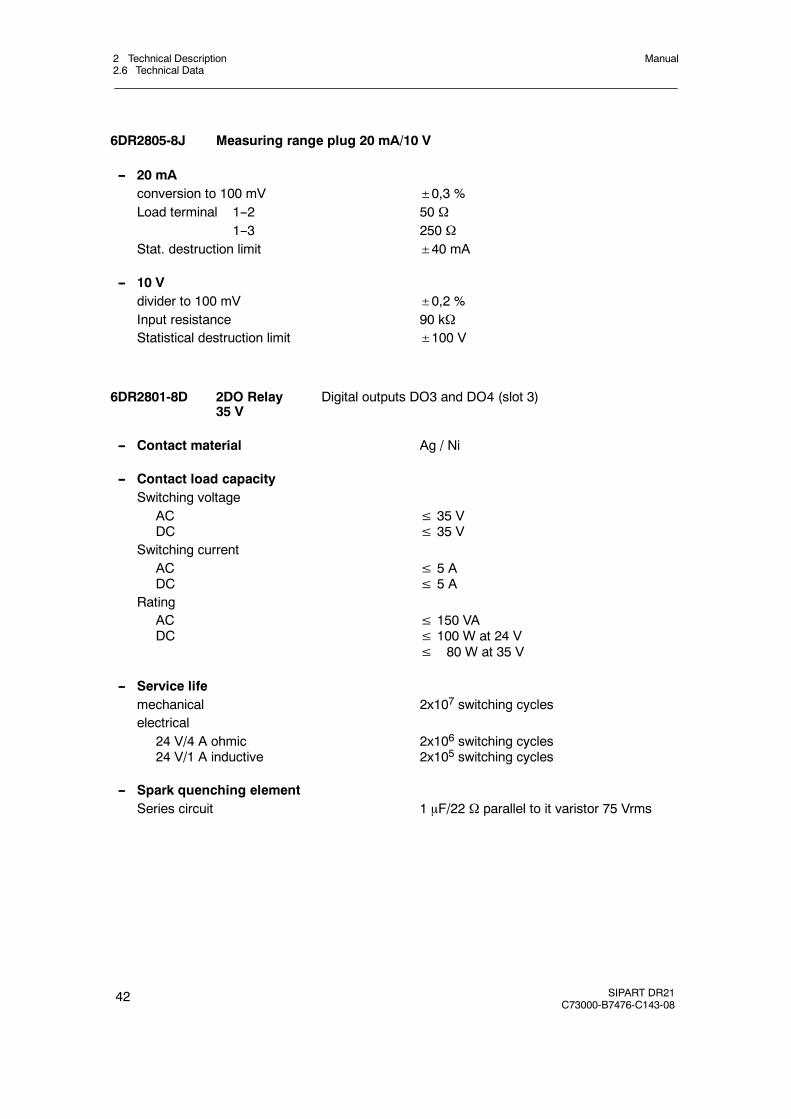
6DR2805-8J Measuring range plug 20 mA/10 V
-- 20 mAconversion to 100 mV ±0,3 %Load terminal 1--2 50 Ω
1--3 250 ΩStat. destruction limit ±40 mA
-- 10 Vdivider to 100 mV ±0,2 %Input resistance 90 kΩStatistical destruction limit ±100 V
6DR2801-8D 2DO Relay35 V
Digital outputs DO3 and DO4 (slot 3)
-- Contact material Ag / Ni
-- Contact load capacitySwitching voltage
ACDC
≤ 35 V≤ 35 V
Switching currentACDC
≤ 5 A≤ 5 A
RatingACDC
≤ 150 VA≤ 100 W at 24 V≤ 80 W at 35 V
-- Service lifemechanical 2x10⁷ switching cycleselectrical
24 V/4 A ohmic24 V/1 A inductive
2x10⁶ switching cycles2x105 switching cycles
-- Spark quenching elementSeries circuit 1 μF/22 Ω parallel to it varistor 75 Vrms

2 Technical Description2.6 Technical Data
Manual
SIPART DR21C73000-B7476-C143-08
43
6DR2801-8E 4DO 24 V, 2DI Digital outputs DO3 to DO6 and DI3 to DI4 (slot 3)
-- Digital outputsSignal status 0 ≤ 1.5 V or open, residual current≤ 50 μASignal status 1 19 to 26 Vload current ≤ 30 mAShort-circuit current ≤ 50 mA, clockingStatic destruction limit --1 V to +35 V
-- Digital inputsSignal status 0 ≤ 4.5 V or openSignal status 1 ≥ 13 VInput resistance ≥ 27 kΩStatic destruction limit 35 V
6DR2801-8C 5DI 24 V Digital inputs DI3 to DI7 (slot 3)
Signal status 0 ≤ 4.5 V or openSignal status 1 ≥ 13 VInput resistance ≥27 kΩStatistical destruction limit ±35 V
6DR2803-8P PROFIBUS-DP
Transmittable signals RS 485, PROFIBUS-DP-protocolTransmittable data Operating state, process variables, para-
meters and structure switchesTransmission procedure PROFIBUS-/DP-protocol
According to DIN 19245, Part 1 and Part 3(EN 50170)
Data rate 9.6 kbit/s to 1.5 Mbit/sexcept 45.45 kBit/s
Station number 0 to 125Time monitoring of the data communication structurable on the controller in connection
with DP-watchdogElectrical isolation between Rxd/Txd-P/-N andthe controller 50 V UC common mode voltageTest voltage 500 V ACRepeater-control signal CNTR-P TTL-level with 1 TTL-load
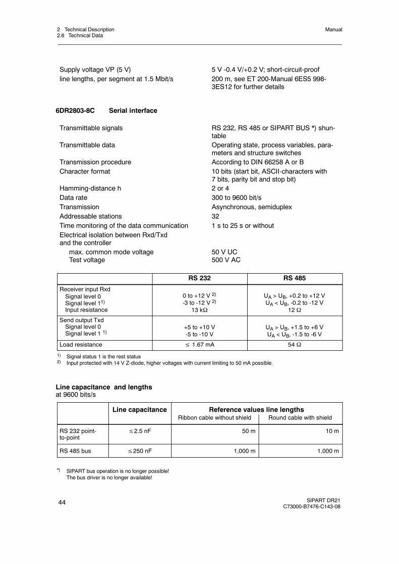
2 Technical Description2.6 Technical Data
Manual
44 SIPART DR21C73000-B7476-C143-08
Supply voltage VP (5 V) 5 V -0.4 V/+0.2 V; short-circuit-proofline lengths, per segment at 1.5 Mbit/s 200 m, see ET 200-Manual 6ES5 998-
3ES12 for further details
6DR2803-8C Serial interface
Transmittable signals RS 232, RS 485 or SIPART BUS *) shun-table
Transmittable data Operating state, process variables, para-meters and structure switches
Transmission procedure According to DIN 66258 A or BCharacter format 10 bits (start bit, ASCII-characters with
7 bits, parity bit and stop bit)Hamming-distance h 2 or 4Data rate 300 to 9600 bit/sTransmission Asynchronous, semiduplexAddressable stations 32Time monitoring of the data communication 1 s to 25 s or withoutElectrical isolation between Rxd/Txdand the controller
max. common mode voltageTest voltage
50 V UC500 V AC
RS 232 RS 485
Receiver input RxdSignal level 0Signal level 11)Input resistance
0 to +12 V 2)
-3 to -12 V 2)
13 kΩ
UA > UB, +0.2 to +12 VUA < UB, -0.2 to -12 V
12 Ω
Send output TxdSignal level 0Signal level 1 1)
+5 to +10 V-5 to -10 V
UA > UB, +1.5 to +6 VUA < UB, -1.5 to -6 V
Load resistance ≤ 1.67 mA 54 Ω
1) Signal status 1 is the rest status2) Input protected with 14 V Z-diode, higher voltages with current limiting to 50 mA possible.
Line capacitance and lengthsat 9600 bits/s
Line capacitance Reference values line lengthspRibbon cable without shield Round cable with shield
RS 232 point-to-point
≤2.5 nF 50 m 10 m
RS 485 bus ≤250 nF 1,000 m 1,000 m
*) SIPART bus operation is no longer possible!The bus driver is no longer available!

2 Technical Description2.6 Technical Data
Manual
SIPART DR21C73000-B7476-C143-08
45
6DR2804-8A/B Coupling relay 230 V
1 relay module 6DR2804-8B2 relay modules 6DR2804-8Aper relay module 2 relays with 1 switching contact each with
spark quenching element
- Contact material Silver-cadmium oxideSwitching voltage
AC ≤ 250 VDC ≤ 250 V
Switching currentAC ≤ 8 ADC ≤ 8 A
RatingAC ≤ 1250 VADC ≤30 W at 250 V
≤100 W at 24 V
- Service lifemechanical 2×10⁷ switching cycleselectrical AC 220 V, ohmic 2×10⁶/I(A) switching cycles
- Spark quenching element Series circuit 22 nF/220 Ω parallelplus varistor 420 V rms
- Exciter windingVoltage +19 to +30 Vresistance 1.2 kΩ180 Ω
- Electrical isolation betweenExciter winding -- contactsRelay module – relay module(6DR2805-8A)
Safe isolation 1) by reinforced isolation, air-and creep lines for overvoltage class III 1)
and degree of contamination 2 1)
contact -- contactof a relay module
Safe isolation 1) by reinforced insulation,air- and creep lines for overvoltage class II1) and degree of contamination 2 1)
1) according to DIN EN 61010 Part 1
- Type of protectionHousing IP50 according to DIN 40050Connections (in plugged state) IP20 according to DIN 40050
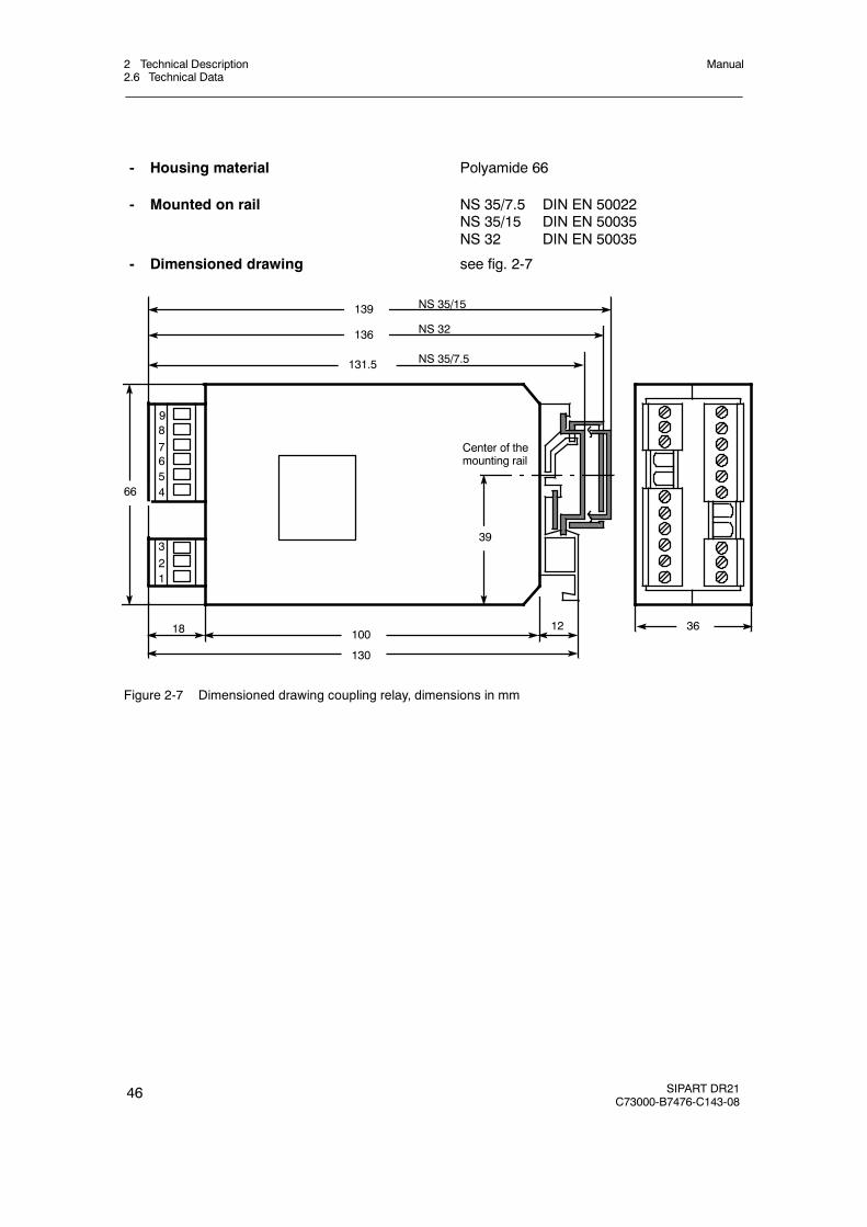
2 Technical Description2.6 Technical Data
Manual
46 SIPART DR21C73000-B7476-C143-08
- Housing material Polyamide 66
- Mounted on rail NS 35/7.5 DIN EN 50022NS 35/15 DIN EN 50035NS 32 DIN EN 50035
- Dimensioned drawing see fig. 2-7
321
87
NS 35/15
Center of themounting rail
1218
9
139
136
100
130
36
131.5
39
66
NS 32
NS 35/7.5
654
Figure 2-7 Dimensioned drawing coupling relay, dimensions in mm

3 Functional description of the structure switches3.1 General
Manual
SIPART DR21C73000-B7476-C143-08
47
3 Functional description of the structure switches
3.1 General
The controller is adapted to the respective job by structure switches. The factory setting corre-sponds to the most usual setting of the individual functions so that only few structure switchesusually need to be set selectively during commissioning. However, it is recommendable to com-pare the compatibility of the individual structure switch settings with the task in any case.
The structure switches S1 and S2 are fundamentally important. With S1 the controller type isset and thus the processing of command variable, main controlled variable and auxiliary con-trolled variables up to control difference generation determined. With S2 the controller outputstructure is set and thus the processing of the automatic-manual-, safety- and tracking variablesas well as the manipulated variable output determined as a K- or S-output.
The functions of structure switches S3 to S81 correspond to the logical order of signal proces-sing. S82 and S83 describe the restart conditions, S84 to S91 the transmission procedure ofthe serial interface.
The structure switches are described in this order in the following description.
. NOTE
The control elements on the front are shown on page 5 and specified by thedigits in the text in brackets. The structure switches are designated by S**.
3.2 Analog input signal processing (S3 to S21)
see fig. 3-1, page 49
Each of the maximum 4 analog inputs is fed through an AD-converter which performs the 50 or60 Hz interference suppression (S3) by averaging over 20 or 16 2/3 ms. Then standardizationto 0 to 100% calculated value takes place per channel of the signal range 0 to 20 mA or 4 to20 mA. The UNI-module is structured with S6> 3 and S8 determines its input signal. S9 deter-mines the thermocouple type when a thermocouple input is chosen. The temperature unit forPT100- or thermocouple signals is determined with S10.
At the same time S4 to S7 decide whether operation is to take place with or without range moni-toring (transmitter fault). A separate AD-converter routine without averaging is responsible formonitoring so that the manual mode which is possible with S50 comes into action bumplessly inthe event of a transmitter fault. The monitor signals per channel on dropping below -2.5% orexceeding +106.25 % with a hysteresis of 0.25 % on the digital x/w-display. By an OR link of allsingle messages the group transmitter fault MUF is formed which can be assigned to the digitaloutputs and negated optionally (see figure 3-1, page 49 and chapter 3.8, page 111). Only theanalog inputs selected with the transmitter fault monitor are monitored, displayed on the frontpanel (the appropriate position stays dark in the case of analog inputs not selected with trans-mitter fault) and signaled with the OR link. The error message is acknowledged with the Shiftkey (12). The fault message signal via the OR link is available until the selected analog inputsare back in the working range.

3 Functional description of the structure switches3.2 Analog input signal processing (S3 to S21)
Manual
48 SIPART DR21C73000-B7476-C143-08
After range monitoring, the 4 analog inputs are each fed through a 1st order filter (parameterst1 to t4 can be set in the parameterization mode onPA). The factory setting is 1 s.
Now the root of every channel can be extracted with S11 to S14 and they can be linearized withS21. This allows non-linear process variables to be represented physically correctly as well (seechapter3.10.4 (page 118 for function principle) setting of the 13 vertex values, see fig. 3-35, page119).
The controllers-, manipulated- or disturbance variables to be processed for the controller types(S1) can be acquired with S15 to S20 from the 4 analog inputs.
The disturbance variable z is connected either by the D-element or directly to the controller out-put (S47). yN serves as a tracking input for the manipulated variable in K-controllers (S2=0) orS-controllers with external feedback (S2=3) and yR as a manipulated variable feedback inS-controllers with internal feedback (S2=2) or as a position feedback in S-controllers with exter-nal feedback (S2=3).
The controllers- or process variables are available for assignment to the analog output (S6) andthe limit value signal (S76 to S80) and can be read in via the SES. With this input structuremost control tasks can be solved in connection with the different controller types and controlleroutput structures.

3 Functional description of the structure switches3.2 Analog input signal processing (S3 to S21)
Manual
SIPART DR21C73000-B7476-C143-08
49
Slot1
S6<
4
4to20
mA
0,1 2,3S4
+ --U
AD
0 1S11
tF1
AI1 I
+1/2
--1/1
AI2 I
+1/4
--1/3
I
S21
1
4to20
mA
0,1 2,3S5
+ --U
AD
0 1S12
tF2
I
S21
2
4to20
mA0,
1
2,3
S6
U
AD
0
S13
tF3
S21
3orA D
+ I
S6≥
4
MA
ME
S8,S9
4
Slot2
U
AD
4to20
mA
0,1 2,
3S7
S3
10
50Hz
60Hz
S21
0 1S14
S21
4
tF4
to 7
50%
S7
0,2
1,3
S6
4,5
6,7
S5
0,2
1,3
S4
0,2
1,3
1,3
--3106
--3106
--3106
--3106
x/wdisplay
Transm
itterfault-
signaling
12
34
S21
0/1/2/3/4
5x1
1 2 3 4S15
0
12
3
4
x2
0 S16
12
3 4
0 S17
x3/w
EA/
wv E
A
12
3 4
0 S18
YN
12
3 4
0 S19
12
3 4
0
S20
YR
Z
0%
0%
0%
0%
0%
0%
MUF
AI3
I,U,R
AI4
I,U,R
0/2/3/4/5
0/1/3/4/5
0/1/2/4/5
0/1/2/3/5
0,2
1UNI
AI1
AI2
AI3 AI4
AI
AI2A
AI1A
AI3A
AI4A
Figure 3-1 Analog input signal processing
3 Functional description of the structure switches3.3 Digital input signal processing (S23 to S41)
Manual
50 SIPART DR21C73000-B7476-C143-08
3.3 Digital input signal processing (S23 to S41)
D Assignment and direction of effect of the digital inputs (S23 to S40)
see figure 3-2, page 52
The control signals CB, He ...bLS, bLPS, tSH are assigned by the structure switches S23 toS33, S92 to the digital inputs DI1 to DI7 or the Lo status. The High status is also possiblewhen assigning CB (S23) and P (S27). The control signals can be negated optionally by thestructure switches S34 to S40.
The digital inputs DI1 and DI2 of the standard controller can be extended by DI3 to DI7 forexample with the option module 5DI (6DR2801-8C) in slot 3 (S22 = 2).
When using the module 4DO 24 V + 2DI (6DR2801-8E) it is possible to extend by two (DI3,DI4) inputs (S22=1).
When using option modules in slot 3, structure switch S22 must be set according to the as-signment, otherwise there will be an error message (see chapter 5.5, page 179 ).
All digital inputs can be read by the SES.
D Linking the digital inputs DI1 to DI7 with the control signals via the SES.(S41, S42, S51 and S85)
see figure 3-3, page 53
The control signal CB (S23) may be available at the digital input (S41) either as a static sig-nal or as a pulse (key operation on control desk). Every positive edge trips the flip-flop whenselecting the pulse input. In the following descriptions the output status of the flip-flop is as-sumed as CB.
All control signals (bLb as of software --B3, tSH as of software --B5) can also be specified inS85 = 2, 3, (4, 5)1) via the SES and or-linked with the corresponding control signals by thedigital inputs. Since the top operation hierarchy in a computer link should be with the autar-chic single controller, the control signals can be switched off by the SES by rounding withRC = Int∧ CB via the Internal/External key (16) of the controller or via CB ES (optionallytime-monitored) or via CBDI (central Computer Fail line) .
In addition the internal flip-flop can be activated at S85 = 2 to 5 parallel to pressing the keysvia IntES.
The CB-signal is formed at S85 = 2, (4)1) as an OR-function of CB ES via the serial interfaceand CB DI via a digital input so that operation can take place optionally with one signal.
1) as of software version --A5
3 Functional description of the structure switches3.3 Digital input signal processing (S23 to S41)
Manual
SIPART DR21C73000-B7476-C143-08
51
At S85 = 3, (5)1) the OR-function is replaced by an AND-function so that the CB set by theSES can be reset via a central Computer Fail line.
At the same time, S85 switches over the sources for the external setpoint wES or wEA andfor the tracking manipulated variable yES or yN. The depth of intervention is determined addi-tionally by the serial interface. This makes it possible to specify the process variables ana-logly for example and the corresponding status signals via the SES.
The function RC = Int∧CB (computer operation) also controls the command variable switch-ing in the controller types S1 = 0 to 4, i.e. also in SPC-operation or the disturbance variableswitching in DDC-operation (see chapter 3.4, page 55).
The two controller types S1 = 5/6 operate without command variable switching. The Internalkey and the control signal CB are available with the link RC = Int∨ CB for locking operationthrough the serial interface (e. g. when linking to control systems).
At S41 = 0 a static switchover by the logic function RC = Int∧CB takes place. In the case ofthe preset to Int (Internal LED (17) off) you can switch statically with CB between controllervalues and computer values (command- and manipulated variables). The computerstandby CB is displayed negated by the C-LED (18) (C = CB, CB = 1≙ C LED off). Thecomputer standby of the controller is signaled negated as a message signal RB = Int. Com-puter operation RC is also signalled negated as a message signal RC = Int∧CB .
At S41 = 1 static switching with acknowledgement takes place. Every time the computer isrecovered (CB from 0! 1) If the internal flip-flop is set to 1 (internal LED on, C LED off), sothat computer operation RC = Int∧CB only becomes effective after pressing the internal key(Int = 0).
With S42 = 0/2 the internal/external key is set out of order and only internal- or externaloperation is pre-selected.
The control signal H is generated as an OR-function by the Manual-/Automatic key (11) withsubsequent flip-flop (Hi) and the control signal He whereby He can be preset by the SES orthe digital inputs in the way described above.
With the structure switch S51 Automatic-/Manual switching can be blocked at the controllerfront (S51 =1 only Automatic or S51 = 2 only Manual. It is still possible to switch to manualoperation by He in the ”Only Automatic” position. The Manual LED (12) always indicates theactive status (see also chapter 3.6, page 94).
At S51 = 0 to 2, He is connected statically by both the SES and the digital inputs. At S51 =3/4 the connection is made dynamically, i.e. every positive edge causes manual-automa-tic-manual operation switching. In addition, with structure switch S51 = 4 the locking of HeESwith RC = Int∨CB is released.
1) as of software version --A5
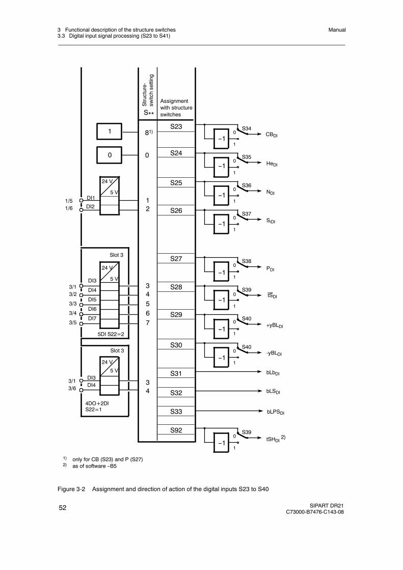
3 Functional description of the structure switches3.3 Digital input signal processing (S23 to S41)
Manual
52 SIPART DR21C73000-B7476-C143-08
3/13/2
3/3
3/4
3/5
1/51/6
3/13/6
DI1
DI3
DI4
DI5
DI6
DI7
DI3DI4
Assignmentwith structureswitches
81)
0
12
34567
34
5DI S22=2
4DO+2DIS22=1
Slot 3
Slot 3
S**
S24
S25
S26
S27
S29
S30
S31
S32
S33
S23CBDI
SiDI
PDI
-yBLDI
+yBLDI
HeDI
NDI
0
1
S341
0
1
S35
0
1
S36
0
1
S37
0
1
S38
0
1
S39
0
1
S40
0
1
S40
S28
bLbDI
bLSDI
bLPSDI
1) only for CB (S23) and P (S27)2) as of software --B5
tSDI
0
24 V
5 V
DI2
24 V
5 V
24 V
5 V
Structure-
switchsetting
S92tSHDI
2)0
1
S39
--1
--1
--1
--1
--1
--1
--1
--1
--1
Figure 3-2 Assignment and direction of action of the digital inputs S23 to S40
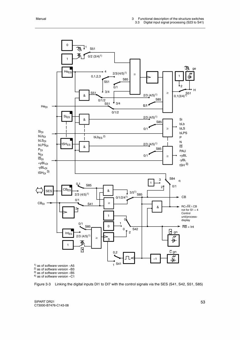
3 Functional description of the structure switches3.3 Digital input signal processing (S23 to S41)
Manual
SIPART DR21C73000-B7476-C143-08
53
0/2 (3/4)1)
S51
4
0/1
CBDI
0,1,2,3
S51
2/3/(4/5)1)
S51 3/4
0/1/2S51 3/4
0/1/2
2/3 (4/5)1)
S85
0,1
0,1
2/3 (4/5)1)
0/1
S85
S41
3/51)S85
CB
02S42
0/1
2/3 (4/5)1)
S85
0,2
S411
1
HeES ≥
&
&
&
SiES
≥ S51
ge
0,1(3/4)1)
2
tSHES
≥
SibLbbLSbLPSPNtSPAU+yBL-yBL
tSH 3)
0/1
01
≥
&
2/3 (4/5)1)
S85
0/1
≥
2/3 (4/5)1)
S85
0/1
H
SES
SiDIbLbDIbLSDIbLPSDIPDINDItSDI+yBLDI-yBLDItSHDI
3)
HeDI
CBES
RC=Int∧CBnot for S1 = 4Controlunit/process-display
&
≥
0/1/2/41)
1
1
0
S≥
RB = Int
--1
1) as of software version --A52) as of software version --B33) as of software version --B54) as of software version --C1
&
bLbES 2)
IntES
S85
2
1
0
C gn
gn
1
1S84
0/1
4)3
2
Figure 3-3 Linking the digital inputs DI1 to DI7 with the control signals via the SES (S41, S42, S51, S85)
3 Functional description of the structure switches3.3 Digital input signal processing (S23 to S41)
Manual
54 SIPART DR21C73000-B7476-C143-08
D Functional explanation of the control signals
CB Computer-standbyDepending on the controller type this digital signal together with theInternal/External key effects either switching in the setpoint range orDDC-operation begins. Central computer-fail-line in SPC and DDC-operation.
He Manual externalThis signal blocks the output of the controller and enables direct manualadjustment of the manipulated variable on the front control panel.
N TrackingWith this signal the output of the K-controller and the three-position-steppercontroller with external position feedback is tracked to the tracking signal y N.
Si Safety operationIn K-controllers and three-position-stepper controllers with external positionfeedback, the manipulated variable adopts the parameterized safety value. Inthree-position-stepper controllers with internal feedback the manipulatedvariable runs independently of the safety setting value to a defined limitposition.
bLS Blocking structuringThe whole configuration is blocked with the exception of the onlineparameterization level.
bLPS Blocking parameterization and structuringThe entire configuring of the instrument is blocked, this means theparameterization as well. Only the normal process operation according to thepreselected controller type is permitted.
bLb Blocking operationThis signal blocks the entire front panel operation of the instrument.
P P-Operation controllerWith this signal the controller is switched to P-operation.
tS setpoint rampThe set setpoint ramp time can be made ineffective with this signal(tS = High≙ ramp switched off).
tSH setpoint hold (setpoint ramp)The setpoint change is stopped with this signal. The setpoint change continueswhen the signal is reset.
yBL Direction-dependent blocking of the manipulated variableDirection-dependent limiting of the manipulated variable by external signals,e.g. from the limit switches of the actuating drives. This limiting is effective inevery operating mode.
3 Functional description of the structure switches3.4 Controller types (S1, S42 to S45)
Manual
SIPART DR21C73000-B7476-C143-08
55
3.4 Controller types (S1, S42 to S45)
3.4.1 General, recurrent functions
D Manual setpoint preset wi or nominal ratio preset wvi on the control front panel.
The internal setpoint can always be adjusted with the±Δw-keys (14, 15) when the greeninternal-LED (1) lights up. The adjusting facility is marked by↗ in the tables. Exceptions tothis rule are expressly mentioned in the individual controller types. The adjustment operatesincrementally, in the first step with a resolution of 1 digit and then an adjustment progressionso that major changes can also be performed quickly. After every interruption in the adjust-ment by releasing the keys, the progression starts again with the smallest adjustment step.
D Setpoint preset wi or nominal ratio preset wvi by the SES
Every time the internal setpoint can be adjusted by the keys (7, 8) on the control front panel,it is also possible to make a preset with the SES. Since only absolute and not incrementaladjustment is possible with the SES, it is advisable to use the setpoint ramp tS to avoidsteps.
In addition, the control signal Int, the automatic-manual switching and the manual manipu-lated variable adjustment can be set via the SES. This makes a complete, parallel processoperation via the SES possible (see also chapter 3.6, page 94 ).
D Source for the external setpoint (S85)
The external setpoint w E may come from two different sources depending on the controllertype.
External setpoint as an absolute value via the analog inputs (wEA) S85 =0, 1, (4, 5)1) orexternal setpoint as an absolute value via the SES (wES) S85 = 2, 3
D Setpoint ramp tS
With the parameter tS (oFPA), the adjustment speed of the active setpoint w (in the ratiocontroller S1 = 3 the active nominal ratio) can be set over 0 to 100 %. At tS = oFF the ad-justment speed moves towards1. With the control signal tS = 1 the set setpoint ramp isswitched off (the setpoint then changes suddenly).
With the setpoint ramp, sudden setpoint switchings to the untracked variables SH, wi, wES atS45 = 1 and wEA, can be avoided.
1) as of software version –A5

3 Functional description of the structure switches3.4 Controller types (S1, S42 to S45)
Manual
56 SIPART DR21C73000-B7476-C143-08
safeSetpoint
externalSetpoint
wE
Δw
ttw
αSH
w
tw =
tan α = 100 %tS
Δwtw
Δw · tS100 %
=
Figure 3-4 Setpoint switching with ramp
The setpoint change/setpoint ramp can be stopped with the control signal tSH. The setpointchange continues when the signal is reset.
D Setpoint limits SA, SE
With the parameters SA and SE (oFPA) the effective setpoint w can be limited to minimumvalue (SA) and maximum value (SE) in the range from -10 to 110 %.
Exception: Ratio controller (S1 = 3)
D Tracking of the ineffective setpoint to the active setpoint (S45)
Normally the ineffective setpoint is tracked to the effective setpoint so that the setpointswitching is bumpless. The internal setpoint (wi) and the external setpoint can be tracked viathe SES (wES). The safety setpoint SH cannot be tracked.
The external setpoint wEA through the analog inputs is only indirectly trackable by trackingthe feeding instrument to the internal setpoint.
At S45 = 1 the tracking is suppressed. This switch setting is always required especially infollow-up controllers if the internal setpoint represents a kind of safety function or if multiplesetpoint operation is to be run in the fixed setpoint controller (S1 = 0).
D x-tracking (S43)
With the structure switch S43 = 1, x-tracking (ratio controller xv-tracking) can be switchedon. This means that the setpoint is tracked to the actual value or the nominal ratio is trackedto the actual ratio and therefore a control difference xd is reset to 0. The tracking alwaystakes place when there is no automatic operation (A). This is the case in manual mode (H),tracking mode (N), DDC-mode and in operation with safety manipulated variable (Si):A = H∨N∨Si
x-tracking in direction-dependent blocking operation is not possible because the P-step pro-duced by resetting the driving control error to blocking direction would immediately cancelthe blocking.
x-tracking takes place without the set setpoint ramp tS. By tracking the setpoint to the actualvalue (nominal ratio to actual ratio), the control difference xd = 0 and automatic operationstarts absolutely bumplessly. Since it can normally be assumed that, especially in manualoperation and in DDC-operation, the actual value has been driven to the desired value dur-ing manual- or DDC-operation, the tracked setpoint then corresponds to the rated value.
3 Functional description of the structure switches3.4 Controller types (S1, S42 to S45)
Manual
SIPART DR21C73000-B7476-C143-08
57
x-tracking only takes full effect if the tracking of the inactive setpoint is locked onto the activesetpoint (S45 = 0) so that not only the active setpoint w but also the setpoint source which issupplying after switching to automatic operation is tracked.
At S45 = 1 (without tracking) the control difference during the A-operation is 0 but the old,untracked setpoint becomes effective again after switching to automatic operation. With thesetpoint ramp tS this step-shaped setpoint change takes place via a time ramp.
This combination is always useful when it is not guaranteed during A-operation (especiallyin safety mode) that the actual value will be driven to the desired rated value by the actuat-ing manipulation and the tracking variable would not be correct in full x-tracking.
D Constants c1 to c7
Linking of the process variables with the constants is possible depending on the controllertype, whereby the constants c1 to c3 are used for the control variable links, the constants c4and c5 for the command variable links.
The constants are set in the parameterization mode onPA.
The constant c6 serves for proportioning the disturbance variable connection z to the con-troller output ya (see figure 3-7, page 62). It can be set in the parameterization mode onPA.
The constant c7 is used in P-controller operation as a factor for increasing the Kp-value.(P/PI-switchover, see figure 3-21, page 92).
D Control signals for the setpoint switching
If available in the single controller types, the setpoint switching takes place depending on thecontrol signals Int (Internal/External key) and CB (Computer standby) as an AND-functionRC = Int∧ CB and its negation. The status of the control signal CB and the Internal key (16)is indicated by the C LED (18) and the Internal LED (17).
With S42 the Internal/External key (16) can be set out of function and can block in the posi-tions Internal or External (see figure 3-3, page 53 ). The factory setting is S42 = 0 (only In-ternal).
With S23, the CB-signal can be set to Low or High or assigned to a digital input, (see fig-ure 3-2, page 52). The factory setting is S23 = 8, CB = High.
The setpoint switching can be varied freely with these structuring possibilities.
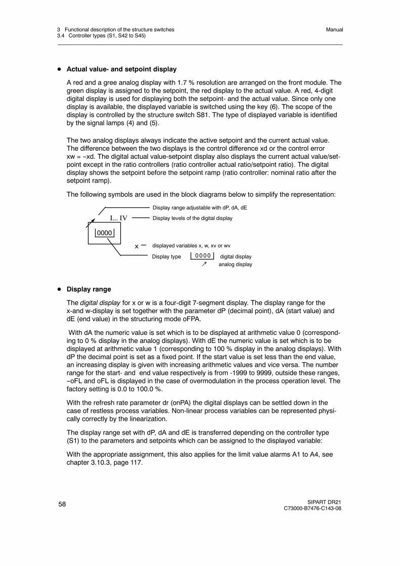
3 Functional description of the structure switches3.4 Controller types (S1, S42 to S45)
Manual
58 SIPART DR21C73000-B7476-C143-08
D Actual value- and setpoint display
A red and a gree analog display with 1.7 % resolution are arranged on the front module. Thegreen display is assigned to the setpoint, the red display to the actual value. A red, 4-digitdigital display is used for displaying both the setpoint- and the actual value. Since only onedisplay is available, the displayed variable is switched using the key (6). The scope of thedisplay is controlled by the structure switch S81. The type of displayed variable is identifiedby the signal lamps (4) and (5).
The two analog displays always indicate the active setpoint and the current actual value.The difference between the two displays is the control difference xd or the control errorxw = --xd. The digital actual value-setpoint display also displays the current actual value/set-point except in the ratio controllers (ratio controller actual ratio/setpoint ratio). The digitaldisplay shows the setpoint before the setpoint ramp (ratio controller: nominal ratio after thesetpoint ramp).
The following symbols are used in the block diagrams below to simplify the representation:
Display type digital display↗ analog display
0000
I... IV
x0000
Display range adjustable with dP, dA, dE
Display levels of the digital display
displayed variables x, w, xv or wv
D Display range
The digital display for x or w is a four-digit 7-segment display. The display range for thex-and w-display is set together with the parameter dP (decimal point), dA (start value) anddE (end value) in the structuring mode oFPA.
With dA the numeric value is set which is to be displayed at arithmetic value 0 (correspond-ing to 0 % display in the analog displays). With dE the numeric value is set which is to bedisplayed at arithmetic value 1 (corresponding to 100 % display in the analog displays). WithdP the decimal point is set as a fixed point. If the start value is set less than the end value,an increasing display is given with increasing arithmetic values and vice versa. The numberrange for the start- and end value respectively is from -1999 to 9999, outside these ranges,--oFL and oFL is displayed in the case of overmodulation in the process operation level. Thefactory setting is 0.0 to 100.0 %.
With the refresh rate parameter dr (onPA) the digital displays can be settled down in thecase of restless process variables. Non-linear process variables can be represented physi-cally correctly by the linearization.
The display range set with dP, dA and dE is transferred depending on the controller type(S1) to the parameters and setpoints which can be assigned to the displayed variable:
With the appropriate assignment, this also applies for the limit value alarms A1 to A4, seechapter 3.10.3, page 117.
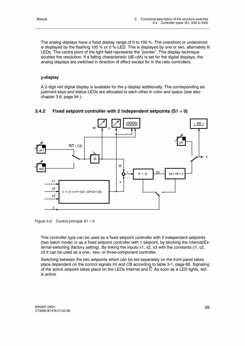
3 Functional description of the structure switches3.4 Controller types (S1, S42 to S45)
Manual
SIPART DR21C73000-B7476-C143-08
59
The analog displays have a fixed display range of 0 to 100 %. The overshoot or undershootis displayed by the flashing 100 % or 0 %-LED. This is displayed by one or two, alternately litLEDs. The centre point of the light field represents the ”pointer”. This display techniquedoubles the resolution. If a falling characteristic (dE<dA) is set for the digital displays, theanalog displays are switched in direction of effect except for in the ratio controllers.
y-display
A 2-digit red digital display is available for the y-display additionally. The corresponding ad-justment keys and status-LEDs are allocated to each other in color and space (see alsochapter 3.6, page 94 ).
3.4.2 Fixed setpoint controller with 2 independent setpoints (S1 = 0)
ya
W
z
x3
x1
x2
ya+c6 S zP I D
W
+
-
wi2
wi1INT∧CB
x = x1+c1S (x2 -c2Sx3+c3)
x
0000
tS
00
yH
y
x
Figure 3-5 Control principle S1 = 0
This controller type can be used as a fixed setpoint controller with 2 independent setpoints(two batch mode) or as a fixed setpoint controller with 1 setpoint, by blocking the Internal/Ex-ternal-switching (factory setting). By linking the inputs x1, x2, x3 with the constants c1, c2,c3 it can be used as a one-, two- or three-component controller.
Switching between the two setpoints which can be set separately on the front panel takesplace dependent on the control signals Int and CB according to table 3-1, page 60. Signalingof the active setpoint takes place on the LEDs Internal and C. As soon as a LED lights, wi2is active.
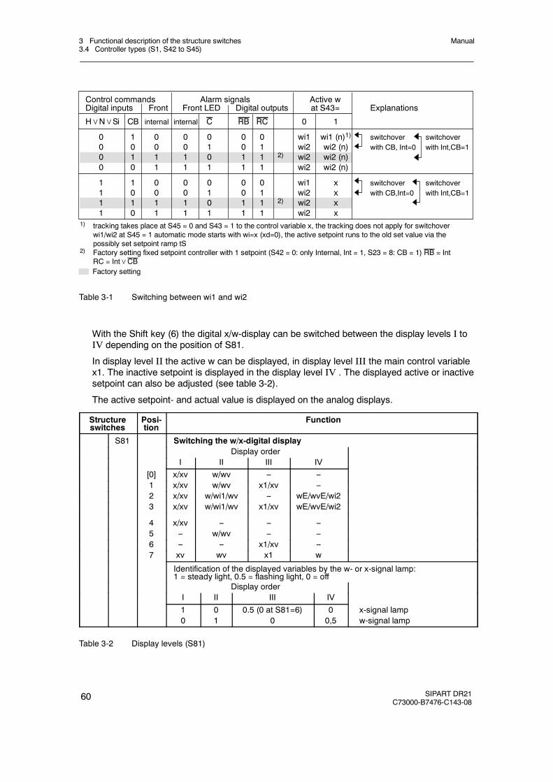
3 Functional description of the structure switches3.4 Controller types (S1, S42 to S45)
Manual
60 SIPART DR21C73000-B7476-C143-08
Control commands Alarm signals Active wDigital inputs Front Front LED Digital outputs at S43= Explanations
H∨N∨Si CB internal internal C RB RC 0 1
0 1 0 0 0 0 0 wi1 wi1 (n)1) switchover switchover0 0 0 0 1 0 1 wi2 wi2 (n) with CB, Int=0 with Int,CB=10 1 1 1 0 1 1 2) wi2 wi2 (n)0 0 1 1 1 1 1 wi2 wi2 (n)
1 1 0 0 0 0 0 wi1 x switchover switchover1 0 0 0 1 0 1 wi2 x with CB,Int=0 with Int,CB=11 1 1 1 0 1 1 2) wi2 x1 0 1 1 1 1 1 wi2 x
1) tracking takes place at S45 = 0 and S43 = 1 to the control variable x, the tracking does not apply for switchoverwi1/wi2 at S45 = 1 automatic mode starts with wi=x (xd=0), the active setpoint runs to the old set value via thepossibly set setpoint ramp tS
2) Factory setting fixed setpoint controller with 1 setpoint (S42 = 0: only Internal, Int = 1, S23 = 8: CB = 1) RB = IntRC = Int∨CBFactory setting
Table 3-1 Switching between wi1 and wi2
With the Shift key (6) the digital x/w-display can be switched between the display levels I toIV depending on the position of S81.
In display level II the active w can be displayed, in display level III the main control variablex1. The inactive setpoint is displayed in the display level IV . The displayed active or inactivesetpoint can also be adjusted (see table 3-2).
The active setpoint- and actual value is displayed on the analog displays.
Structureswitches
Posi-tion
Function
S81 Switching the w/x-digital displayDisplay order
I II III IV[0] x/xv w/wv -- --1 x/xv w/wv x1/xv --2 x/xv w/wi1/wv -- wE/wvE/wi23 x/xv w/wi1/wv x1/xv wE/wvE/wi2
4 x/xv -- -- --5 -- w/wv -- --6 -- -- x1/xv --7 xv wv x1 w
Identification of the displayed variables by the w- or x-signal lamp:1 = steady light, 0.5 = flashing light, 0 = off
Display orderI II III IV
1 0 0.5 (0 at S81=6) 0 x-signal lamp0 1 0 0,5 w-signal lamp
Table 3-2 Display levels (S81)
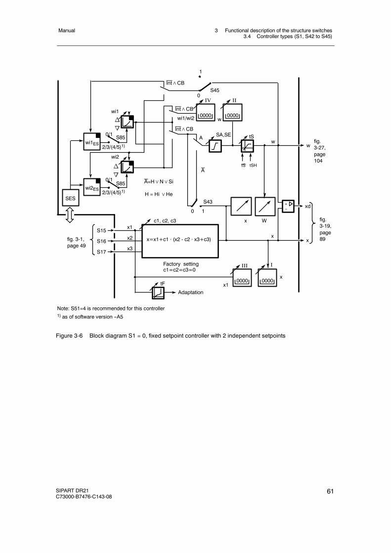
3 Functional description of the structure switches3.4 Controller types (S1, S42 to S45)
Manual
SIPART DR21C73000-B7476-C143-08
61
0S45
Int∧CB
xd
S85
2/3/(4/5)1)
0/1
0
c1, c2, c3
x
x
w
W
S15
S16
S17
Factory settingc1=c2=c3=0
x=x1+c1 · (x2 - c2 · x3+c3)x2
x1
x3
tF
tSSA,SE
wi1
n
o
1
S43
Adaptation
SES
wi1ES
Int∧CB
Int∧CB
A
A
x1
x
A=H∨N∨Si
IV II
I
x
0000 0000w
H = Hi∨He
III
0000 0000
+--
wi1/wi2
S85
2/3/(4/5)1)
0/1
wi2
wi2ES
n
o
wfig.3-27,page104
Note: S51=4 is recommended for this controller1) as of software version --A5
fig. 3-1,page 49
fig.3-19,page89
1
tS tSH
Figure 3-6 Block diagram S1 = 0, fixed setpoint controller with 2 independent setpoints
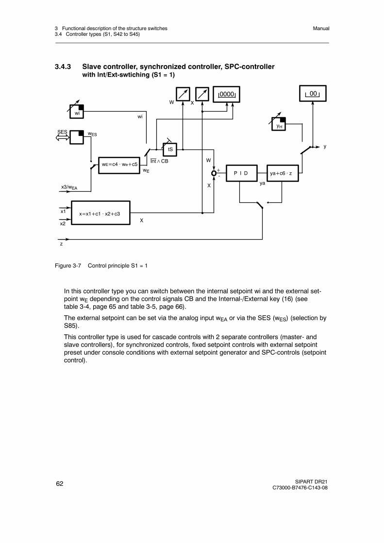
3 Functional description of the structure switches3.4 Controller types (S1, S42 to S45)
Manual
62 SIPART DR21C73000-B7476-C143-08
3.4.3 Slave controller, synchronized controller, SPC-controllerwith Int/Ext-swtiching (S1 = 1)
SES
wE=c4 · we+c5wE
wi
wES
x3/wEAya
W X
W
+-
X
P I D ya+c6 · z
0000
z
x1 x=x1+c1 · x2+c3Xx2
tSy
yH
00
wi
Int∧CB
Figure 3-7 Control principle S1 = 1
In this controller type you can switch between the internal setpoint wi and the external set-point wE depending on the control signals CB and the Internal-/External key (16) (seetable 3-4, page 65 and table 3-5, page 66).
The external setpoint can be set via the analog input wEA or via the SES (wES) (selection byS85).
This controller type is used for cascade controls with 2 separate controllers (master- andslave controllers), for synchronized controls, fixed setpoint controls with external setpointpreset under console conditions with external setpoint generator and SPC-controls (setpointcontrol).

3 Functional description of the structure switches3.4 Controller types (S1, S42 to S45)
Manual
SIPART DR21C73000-B7476-C143-08
63
D SPC-controls
Here a process computer takes over command of the setpoint during computer operationRC = Int∧CB = 1. In the case of computer failure (CB from 1! 0) the controller takes overeither the last computer setpoint (tracked wi) or the safety setpoint SH (selection via S44).
D Cascade controls
A command controller, e.g. a fixed setpoint controller (with the main controlled variable)feeds the external setpoint of a slave controller with its manipulated variable (with the auxili-ary controlled variable) and this the final control element. This gives faster control of themain controlled variable in the event of changes in the auxiliary controlled variable, e.g. fur-nace temperature control (furnace temperature, main controlled variable) with different flowof the medium to be heated (auxiliary controlled variable).
D Slave controls
A command controller feeds several synchronized controllers simultaneously whose individ-ual setpoints can be set in a ratio to each other by the constants c4 and c5 and then dragthe controlled variables accordingly (controlled variable synchronization).
D Control signals for the setpoint switching
The setpoint switching takes place via the logic link RC = Int∧CB and its negation (see table3-4, page 65 and table 3-5, page 66). Both control signals can be set statically to 1 or 0 (intvia S49, CB via S24) in addition to their normal functions as Shift key or control signal withthe states 1 and 0, see fig. 3-2, page 52 and fig. 3-3, page 53.
The factory setting is Int = 1 (S42 = 0) and CB=1 (S23 = 8), so that the internal setpointwi is always active and cannot be switched in the factory setting
With this setting option it is possible to make the setting only dependent on Int (S42=2,S23= 8) or only dependent on CB (S42=1, S23=1 to 7) as a slave controller with Internal/Exter-nal-switching. If the switching option is blocked in External position (S42=1, S23=8), the con-troller operates as a slave controller without Internal/External-switching.

3 Functional description of the structure switches3.4 Controller types (S1, S42 to S45)
Manual
64 SIPART DR21C73000-B7476-C143-08
D Display of the external setpoint wE
With the Shift key (6) the digital x/w-display can be switched between the display levels I toIV depending on the position of S81.
In display level II the active w can be displayed, in display level III the main control variablex1. The external setpoint wE is displayed in display level IV. The displayed active or inactivesetpoint can also be adjusted (see table 3-3).
The active setpoint- and actual value are displayed on the analog displays.
Structureswitches
Posi-tion
Function
S81 Switching the w/x-digital displayDisplay order
I II III IV[0] x/xv w/wv -- --1 x/xv w/wv x1/xv --2 x/xv w/wi1/wv -- wE/wvE/wi23 x/xv w/wi1/wv x1/xv wE/wvE/wi2
4 x/xv -- -- --5 -- w/wv -- --6 -- -- x1/xv --7 xv wv x1 w
Identification of the displayed variables by the w- or x-signal lamp:1 = steady light, 0.5 = flashing light, 0 = off
Display orderI II III IV1 0 0.5 (0 at S81=6) 0 x-signal lamp0 1 0 0,5 w-signal lamp
Table 3-3 Display levels (S81)
D Operation with 2 or 3 setpoints
If tracking of the inactive setpoint to the active setpoint is blocked with S45 = 1, a multiplesetpoint operation (switching between wi, wE and SH is achieved (see table 3-4, page 65)and table 3-5, page 66.
D Controlled variable processing
A 2-component control is implemented (disturbance variable connection). With factors c1and c3 the main controlled variable x1 can connect the auxiliary controlled variable x2 withweighting.
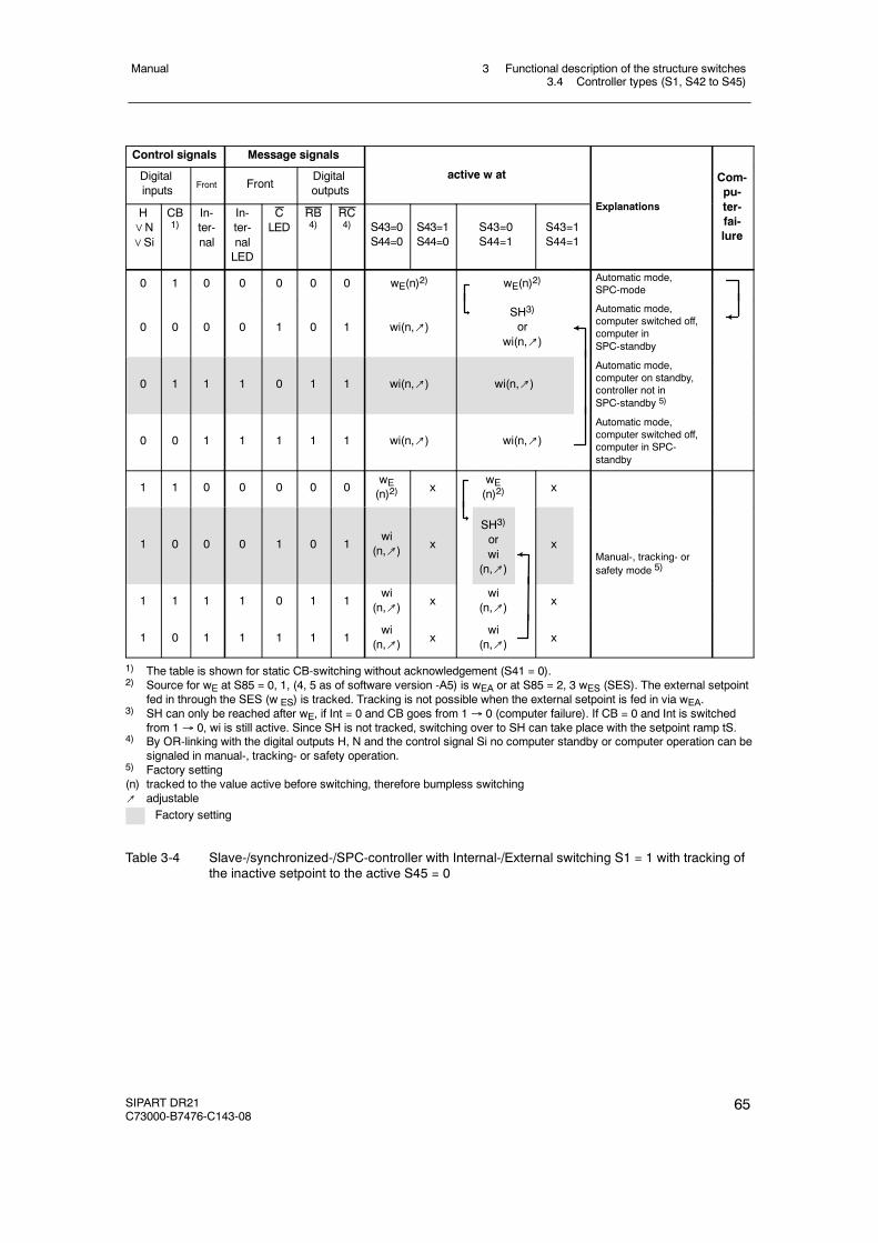
3 Functional description of the structure switches3.4 Controller types (S1, S42 to S45)
Manual
SIPART DR21C73000-B7476-C143-08
65
Control signals Message signals
Digitalinputs Front Front
Digitaloutputs
active w at
E l ti
Com-pu-tH
∨N∨Si
CB1)
In-ter-nal
In-ter-nalLED
CLED
RB4)
RC4) S43=0
S44=0S43=1S44=0
S43=0S44=1
S43=1S44=1
Explanations ter-fai-lure
0 1 0 0 0 0 0 wE(n)2) wE(n)2)Automatic mode,SPC-mode
0 0 0 0 1 0 1 wi(n,↗)SH3)
orwi(n,↗)
Automatic mode,computer switched off,computer inSPC-standby
0 1 1 1 0 1 1 wi(n,↗) wi(n,↗)
Automatic mode,computer on standby,controller not inSPC-standby 5)
0 0 1 1 1 1 1 wi(n,↗) wi(n,↗)
Automatic mode,computer switched off,computer in SPC-standby
1 1 0 0 0 0 0wE(n)2) x
wE(n)2) x
1 0 0 0 1 0 1wi
(n,↗) x
SH3)
orwi
(n,↗)
xManual-, tracking- orsafety mode 5)
1 1 1 1 0 1 1wi
(n,↗) xwi
(n,↗) x
1 0 1 1 1 1 1wi
(n,↗) xwi
(n,↗) x
1) The table is shown for static CB-switching without acknowledgement (S41 = 0).2) Source for wE at S85 = 0, 1, (4, 5 as of software version -A5) is wEA or at S85 = 2, 3 wES (SES). The external setpoint
fed in through the SES (w ES) is tracked. Tracking is not possible when the external setpoint is fed in via wEA.3) SH can only be reached after wE, if Int = 0 and CB goes from 1→ 0 (computer failure). If CB = 0 and Int is switched
from 1→ 0, wi is still active. Since SH is not tracked, switching over to SH can take place with the setpoint ramp tS.4) By OR-linking with the digital outputs H, N and the control signal Si no computer standby or computer operation can be
signaled in manual-, tracking- or safety operation.5) Factory setting(n) tracked to the value active before switching, therefore bumpless switching↗ adjustable
Factory setting
Table 3-4 Slave-/synchronized-/SPC-controller with Internal-/External switching S1 = 1 with tracking ofthe inactive setpoint to the active S45 = 0

3 Functional description of the structure switches3.4 Controller types (S1, S42 to S45)
Manual
66 SIPART DR21C73000-B7476-C143-08
Control signals Message signals
Digitalinputs Front Front
Digitaloutputs
active w at
E l tiH∨N∨Si
CB1)
Inter-nal
In-ter-nalLED
CLED
RB4)
RC4) S43=0
S44=0S43=1S44=0
S43=0S44=1
S43=1S44=1
Explanations
0 1 0 0 0 0 0 wE2) wE2)
0 0 0 0 1 0 1 wi(↗)SH3)
orwi(↗) Automatic mode 5)
0 1 1 1 0 1 1 wi(↗) wi(↗)
0 0 1 1 1 1 1 wi(↗) wi,↗)
1 1 0 0 0 0 0 wE2) x wE2) x
1 0 0 0 1 0 1 wi(↗) x
SH3)
orwi(↗)
x Manual-, tracking- or safetymode 5)
1 1 1 1 0 1 1 wi(↗) x wi(↗) x
1 0 1 1 1 1 1 wi(↗) x wi(↗) x
1) The table is shown for static computer switching without acknowledgement (S41 = 0).2) Source for wE at S85 = 1, 2, (4, 5 as of software version -A5) is wEA or at S85 = 3, 4 wES. Switching between the set-
points can take place with the setpoint ramp tS.3) SH can only be reached after wE, if Int = 0 and CB goes from 1→ 0 (computer failure). If CB = 0 and Int is switched
from 1→ 0, wi is still active. Since SH is not tracked, switching over to SH can take place with the setpoint ramp tS.4) By OR-linking with the digital outputs H, N and the control signal Si no computer standby or computer operation can be
signaled in manual-, tracking- or safety operation.5) Factory setting↗ adjustable
Factory setting
Table 3-5 Slave-/synchronized-/SPC controller with Internal-/External switching (SPC-controller), S1 =1 without tracking of the active setpoint to the active setpoint S45 = 1, 2 or 3 setpoint oper-ation

3 Functional description of the structure switches3.4 Controller types (S1, S42 to S45)
Manual
SIPART DR21C73000-B7476-C143-08
67
Factorysetting
c1=c3=0
S85
tS
wES
xxdwE
A
0
2/3
1
11
0
0
CB
CB
AIntInt
wi
wE
X
X
W
W
SA,SE
c1,c3
tFI
x1 x2
x3/w
EA
S43
S44S45
Adaptation
x=x1+c1·x2+c3
wES
w-c3
c4SH w
E=c4·wE+c5
wE
c4,c5
Factorysetting
c4=1,c5
=0
wn owi1
S85
wi1ES
SES
2/3/(4/5)1)
0/1
1)
S17,
S15,
S16,
w
0/1/(4/5)1)
0000
I
0000III
xx1
--+
0000
II
0000IV
A=H∨N∨Si
H=Hi∨
He
Note:S51
=4isrecommendedforthiscontroller
1)as
ofsoftw
areversion-A5
Figure
3-27,
page
104
Figure3-1,
page
49
Figure
3-19,
page
89
tStSH
Figure 3-8 Block diagram S1 = 1 slave controller, synchronized controller, SPC-controller
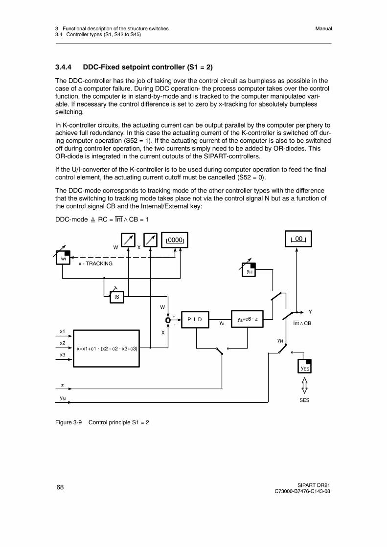
3 Functional description of the structure switches3.4 Controller types (S1, S42 to S45)
Manual
68 SIPART DR21C73000-B7476-C143-08
3.4.4 DDC-Fixed setpoint controller (S1 = 2)
The DDC-controller has the job of taking over the control circuit as bumpless as possible in thecase of a computer failure. During DDC operation- the process computer takes over the controlfunction, the computer is in stand-by-mode and is tracked to the computer manipulated vari-able. If necessary the control difference is set to zero by x-tracking for absolutely bumplessswitching.
In K-controller circuits, the actuating current can be output parallel by the computer periphery toachieve full redundancy. In this case the actuating current of the K-controller is switched off dur-ing computer operation (S52 = 1). If the actuating current of the computer is also to be switchedoff during controller operation, the two currents simply need to be added by OR-diodes. ThisOR-diode is integrated in the current outputs of the SIPART-controllers.
If the U/I-converter of the K-controller is to be used during computer operation to feed the finalcontrol element, the actuating current cutoff must be cancelled (S52 = 0).
The DDC-mode corresponds to tracking mode of the other controller types with the differencethat the switching to tracking mode takes place not via the control signal N but as a function ofthe control signal CB and the Internal/External key:
DDC-mode≙ RC = Int∧CB = 1
YW
x3
x1
x2
P I D
W
+
-
X
wi
x=x1+c1 · (x2 - c2 · x3+c3)
X
0000
ya+c6 · z
z
yH
ya
yN
00
x - TRACKING
yN
yES
SES
Int∧CB
tS
Figure 3-9 Control principle S1 = 2
3 Functional description of the structure switches3.4 Controller types (S1, S42 to S45)
Manual
SIPART DR21C73000-B7476-C143-08
69
The DDC-mode is signaled like the tracking mode in the other controller types by the lit y-Exter-nal-LED. The status of the control signal CB and the Internal/External key is displayed by theLEDs C and Internal. During the DDC-mode the setpoint is prepared by tracking to the com-puter failure. The setpoint is always displayed which would become active after the computerfailure.
With S50 a choice is made between x-tracking and wi, with S44 the safety setpoint is preset.
With S49 the priority between DDC-mode and manual mode is determined. If DDC-mode haspriority over manual mode, you can select with the manual-automatic switching whetheroperation is to continue after a computer failure in automatic- or manual mode. If you need tointervene manually in computer operation, you have to switch to Internal-mode in addition toswitching over to manual mode, then the LEDs Internal (17) and Manual (12) light up, the LEDy-External (13) goes out, the non-lit LED C (18) still indicates computer standby.
If manual mode has priority over DDC-mode you can switch directly from computer operation tomanual operation. Then the Manual LED (12) lights, the y-External LED (13) goes out, the darkLEDs Internal (17) and C (18) still indicate computer standby of the controller or computerstandby.
Automatic mode is always switched to here in the event of a computer failure.
D DDC-control unit
The DDC-control unit function is obtained with S49 = 0 and with S51 = 2 (manual modeonly). In computer operation the manipulated variable is fed through y N, manual operation isalways active after a computer failure. If you want to switch over to manual operation duringcomputer operation, the computer operation must be switched off with the Internal key (16).
The actual value can be indicated on the actual value display.
SH as a flag pointer or wi can be indicated on the setpoint display.

3 Functional description of the structure switches3.4 Controller types (S1, S42 to S45)
Manual
70 SIPART DR21C73000-B7476-C143-08
Footnote explanation, see page 72
Table 3-6 DDC controller, S1 = 2, manual operation has priority over DDC operation S49 = 1
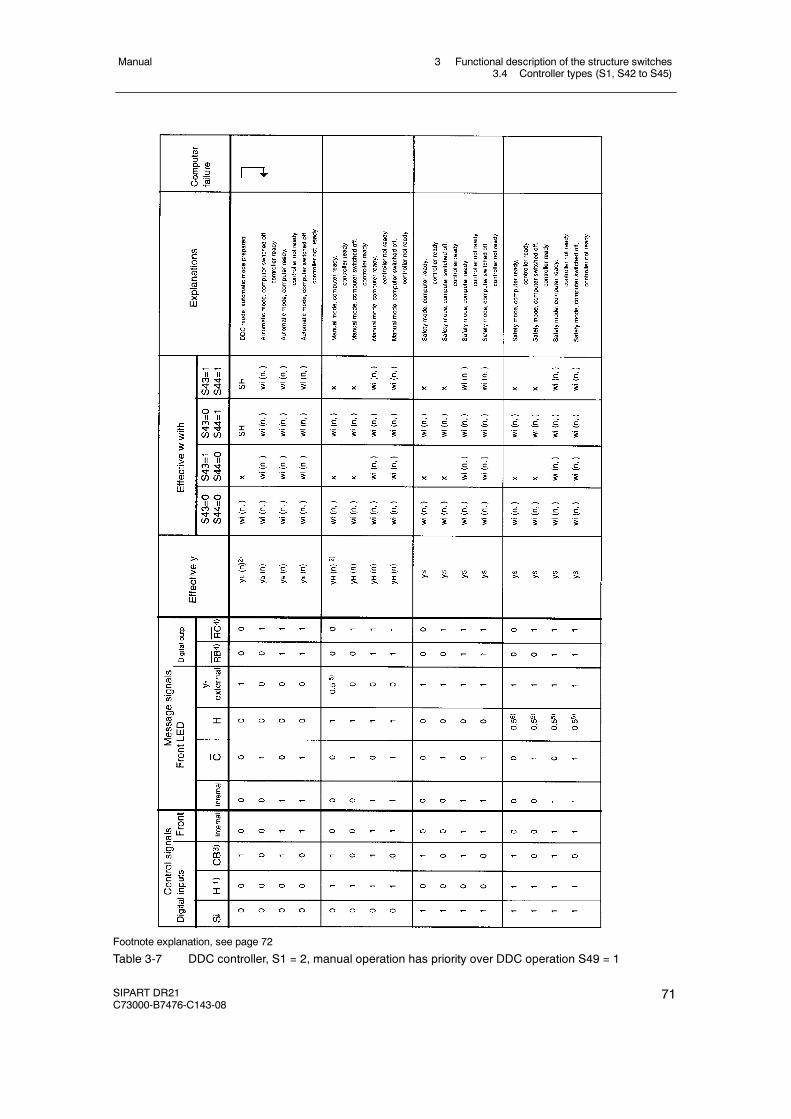
3 Functional description of the structure switches3.4 Controller types (S1, S42 to S45)
Manual
SIPART DR21C73000-B7476-C143-08
71
Footnote explanation, see page 72
Table 3-7 DDC controller, S1 = 2, manual operation has priority over DDC operation S49 = 1
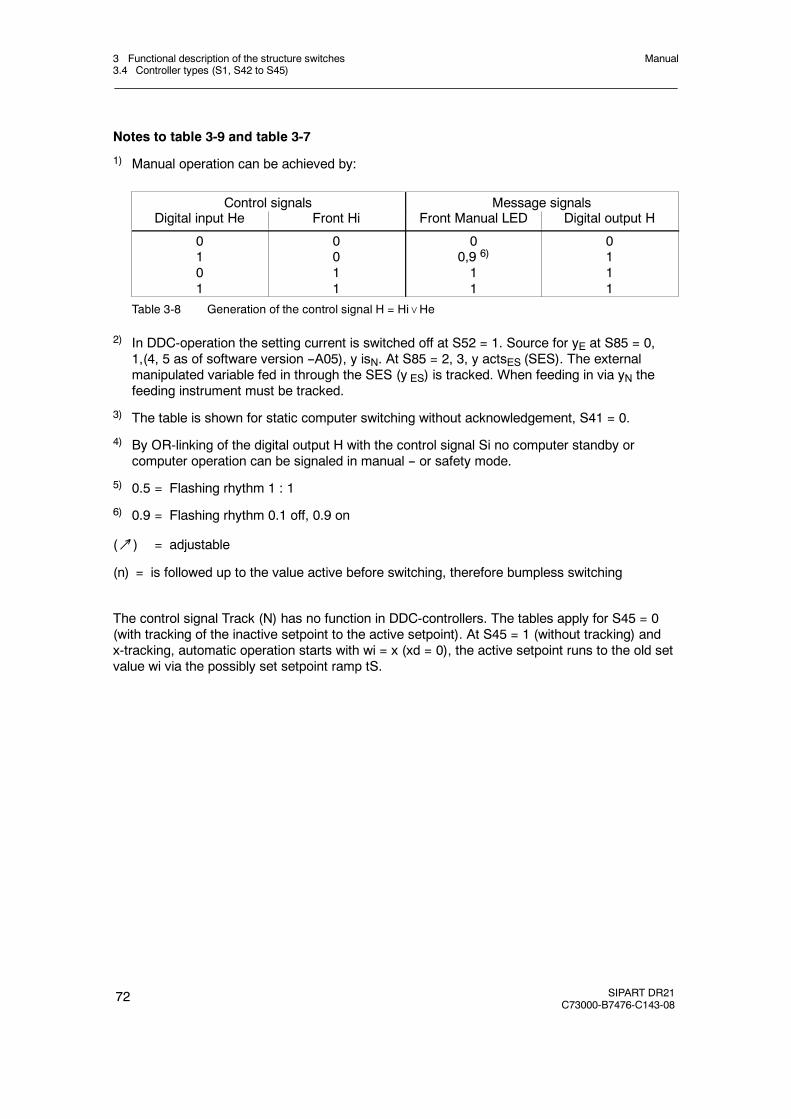
3 Functional description of the structure switches3.4 Controller types (S1, S42 to S45)
Manual
72 SIPART DR21C73000-B7476-C143-08
Notes to table 3-9 and table 3-7
1) Manual operation can be achieved by:
Control signals Message signalsDigital input He Front Hi Front Manual LED Digital output H
0101
0011
00,9 6)
11
0111
Table 3-8 Generation of the control signal H = Hi∨He
2) In DDC-operation the setting current is switched off at S52 = 1. Source for yE at S85 = 0,1,(4, 5 as of software version --A05), y isN. At S85 = 2, 3, y actsES (SES). The externalmanipulated variable fed in through the SES (y ES) is tracked. When feeding in via yN thefeeding instrument must be tracked.
3) The table is shown for static computer switching without acknowledgement, S41 = 0.
4) By OR-linking of the digital output H with the control signal Si no computer standby orcomputer operation can be signaled in manual -- or safety mode.
5) 0.5 = Flashing rhythm 1 : 1
6) 0.9 = Flashing rhythm 0.1 off, 0.9 on
(↗) = adjustable
(n) = is followed up to the value active before switching, therefore bumpless switching
The control signal Track (N) has no function in DDC-controllers. The tables apply for S45 = 0(with tracking of the inactive setpoint to the active setpoint). At S45 = 1 (without tracking) andx-tracking, automatic operation starts with wi = x (xd = 0), the active setpoint runs to the old setvalue wi via the possibly set setpoint ramp tS.
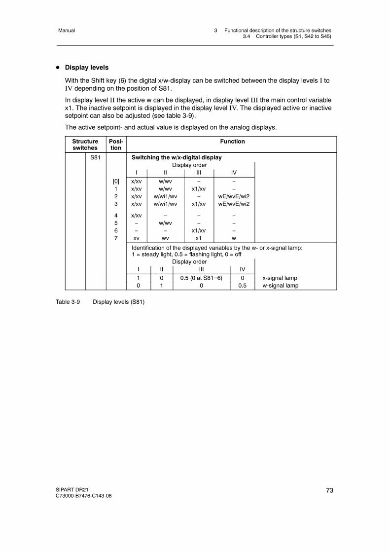
3 Functional description of the structure switches3.4 Controller types (S1, S42 to S45)
Manual
SIPART DR21C73000-B7476-C143-08
73
D Display levels
With the Shift key (6) the digital x/w-display can be switched between the display levels I toIV depending on the position of S81.
In display level II the active w can be displayed, in display level III the main control variablex1. The inactive setpoint is displayed in the display level IV. The displayed active or inactivesetpoint can also be adjusted (see table 3-9).
The active setpoint- and actual value is displayed on the analog displays.
Structureswitches
Posi-tion
Function
S81 Switching the w/x-digital displayDisplay order
I II III IV[0] x/xv w/wv -- --1 x/xv w/wv x1/xv --2 x/xv w/wi1/wv -- wE/wvE/wi23 x/xv w/wi1/wv x1/xv wE/wvE/wi2
4 x/xv -- -- --5 -- w/wv -- --6 -- -- x1/xv --7 xv wv x1 w
Identification of the displayed variables by the w- or x-signal lamp:1 = steady light, 0.5 = flashing light, 0 = off
Display orderI II III IV1 0 0.5 (0 at S81=6) 0 x-signal lamp0 1 0 0,5 w-signal lamp
Table 3-9 Display levels (S81)
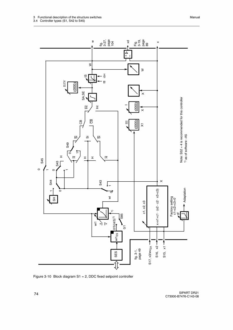
3 Functional description of the structure switches3.4 Controller types (S1, S42 to S45)
Manual
74 SIPART DR21C73000-B7476-C143-08
I
X1
X
0
wi
CB
0
S44
1
0 1
S45
S43
0
H
1
S43
1
Si
H H
Int
W
W
X
tFc1,c2,c3
1
Factorysetting
c1=c2=c3=0
x=x1+c1·(x2
-c2
·x3+c3)
Adaptation
x
X
CB
SA,SE
tS
0S49
SH
III
w
n owi1
S85
wi1ES
SES
2/3/(4/5)1)
0/1
1)
Note:S52
=4isrecommendedforthiscontroller
1)as
ofsoftw
are--A
5
S17,x3/wv E
A
S16,x2
S15,x1
Int
--+
0000
0000
0000II/IV
fig.
3-27,
page
104
fig.3-1,
page
49Fig.
3-19,
page
89
HHSi
Si
xd
tStSH
Figure 3-10 Block diagram S1 = 2, DDC fixed setpoint controller
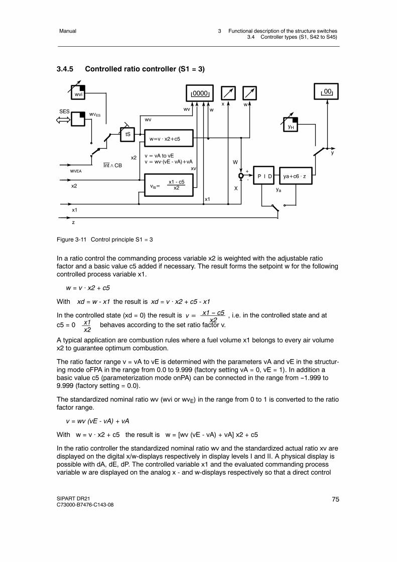
3 Functional description of the structure switches3.4 Controller types (S1, S42 to S45)
Manual
SIPART DR21C73000-B7476-C143-08
75
3.4.5 Controlled ratio controller (S1 = 3)
wVES
x wwv
x2
wv
x1
x2
wVEA
vis=x1 - c5x2 ya
W
+
-
X
P I D ya+c6 · z
y
yH
z
0000
w=v · x2+c5tS
wvi
SES
00
v = vA to vEv = wv·(vE - vA)+vA
xv
x1
w
Int∧CB
Figure 3-11 Control principle S1 = 3
In a ratio control the commanding process variable x2 is weighted with the adjustable ratiofactor and a basic value c5 added if necessary. The result forms the setpoint w for the followingcontrolled process variable x1.
w = v · x2 + c5
With xd = w - x1 the result is xd = v · x2 + c5 - x1
In the controlled state (xd = 0) the result is v = x1 -- c5x2
, i.e. in the controlled state and atc5 = 0 x1
x2behaves according to the set ratio factor v.
A typical application are combustion rules where a fuel volume x1 belongs to every air volumex2 to guarantee optimum combustion.
The ratio factor range v = vA to vE is determined with the parameters vA and vE in the structur-ing mode oFPA in the range from 0.0 to 9.999 (factory setting vA = 0, vE = 1). In addition abasic value c5 (parameterization mode onPA) can be connected in the range from --1.999 to9.999 (factory setting = 0.0).
The standardized nominal ratio wv (wvi or wvE) in the range from 0 to 1 is converted to the ratiofactor range.
v = wv (vE - vA) + vA
With w = v · x2 + c5 the result is w = [wv (vE - vA) + vA] x2 + c5
In the ratio controller the standardized nominal ratio wv and the standardized actual ratio xv aredisplayed on the digital x/w-displays respectively in display levels I and II. A physical display ispossible with dA, dE, dP. The controlled variable x1 and the evaluated commanding processvariable w are displayed on the analog x - and w-displays respectively so that a direct control

3 Functional description of the structure switches3.4 Controller types (S1, S42 to S45)
Manual
76 SIPART DR21C73000-B7476-C143-08
difference monitoring is possible at all times. At S81 = 7, x1 and w can be displayed on thedigital x/w-display in the levels III and IV. A physical display is possible with Pd, Ad, Ed.
At S81 = 2 or 3, the digital x/w-display can be switched to the external nominal ratio wvE(display level IV). The digital x/w-display indicates the actual ratio xy in display levels I and III.Switching between wvi and wvE takes place in the same way as in the slave controllerS1 = 1.
The actual ratio is gained by back calculating the ratio formula with the current process vari-ables x1, x2:
vis = x1-c5x2
with vist = xv (vE -- vA) + vA the result is for xv = vis-vAvE-vA or xv = vE-vA
x1-c5x2
- vA
xv is displayed and is required for x-tracking-mode. For the xv-display, x1 and x2 are limited to+0.5 % so that the display does not become too restless for small x1 and x2 or flip from positiveto negative in the case of negative x2. The linearization of the commanding process variable x2or the following process variable x1 is possible (S21).The linearization then acts on the analog displays and the ratio formation and therefore in-directly on the digital displays for nominal- and actual ratio. The ratio controller has no nominalratio limiting because the ratio factor range already marks the limit.
With the Shift key (6) the digital x/w-display can be switched between the display levels I to IVdepending on the position of S81.
In display level II the active nominal ratio wy can be displayed, in dispaly level I/III the actualratio xy. The external setpoint wyE is displayed in display level IV. The displayed active or exter-nal nominal ratio can also be adjusted.The active setpoint- and actual value is displayed on the analog displays (see table 3-10).
Structureswitches
Posi-tion
Function
S81 Switching the w/x-digital displayDisplay order
I II III IV[0] x/xv w/wv -- --1 x/xv w/wv x1/xv --2 x/xv w/wi1/wv -- wE/wvE/wi23 x/xv w/wi1/wv x1/xv wE/wvE/wi2
4 x/xv -- -- --5 -- w/wv -- --6 -- -- x1/xv --7 xv wv x1 w
Identification of the displayed variables by the w- or x-signal lamp:1 = steady light, 0.5 = flashing light, 0 = off
Display orderI II III IV1 0 0.5 (0 at S81=6) 0 x-signal lamp0 1 0 0,5 w-signal lamp
Table 3-10 Display levels (S81)
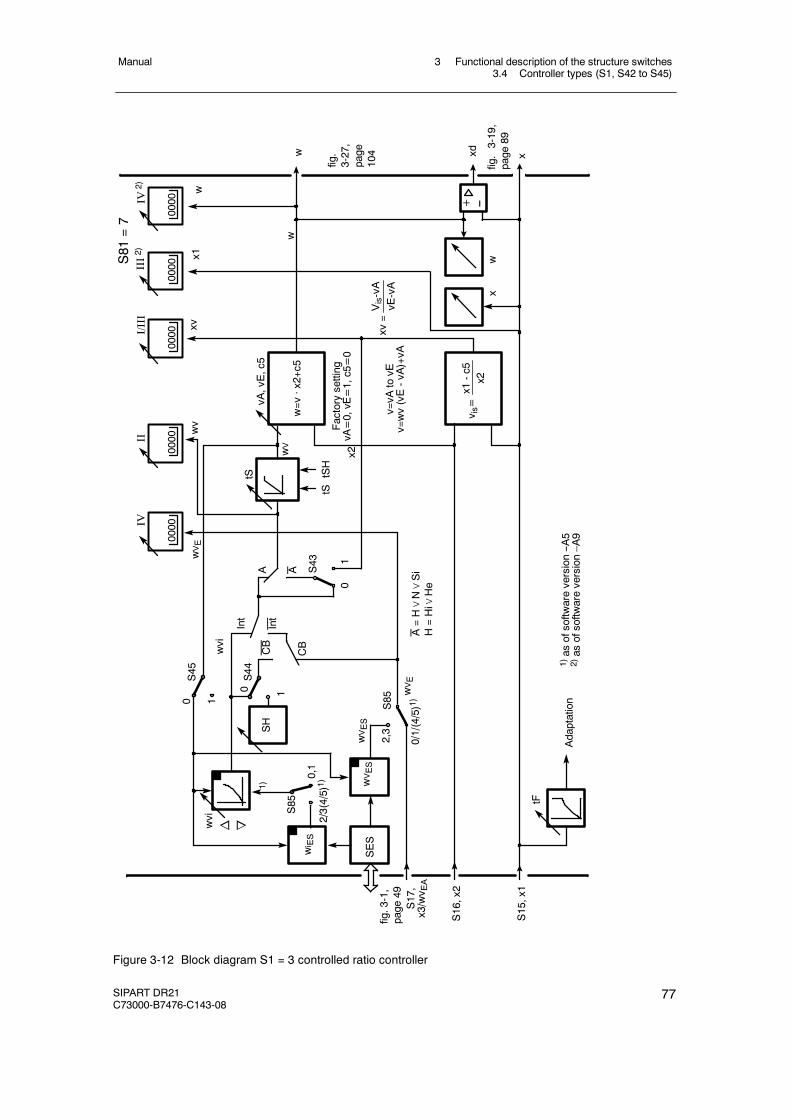
3 Functional description of the structure switches3.4 Controller types (S1, S42 to S45)
Manual
SIPART DR21C73000-B7476-C143-08
77
CBwvi
0
AA
1
10
0
wV
Adaptation
xw
CB
S85
w
xv=
tF
x2
S43
S45
S44
Int
wv
xv
Factorysetting
vA=0,vE=1,c5=0
SH
vA,vE,c5
tS
IVII
I/III
w=v
·x2+c5
v is=x1-c5
x2
v=vA
tovE
v=wv(vE-vA)+vA
xd x
2,3
Vis-vA
vE-vA
1
w
S17,
x3/wv E
A
S16,x2
S15,x1
1)as
ofsoftw
areversion--A
52)as
ofsoftw
areversion–A
9
SES
n owvi
0/1/(4/5)1)
wVES
wi ES
S85
0,1
2/3(4/5)1)1)
IV2) w
III2) x1S81
=7
wVES
A=H∨N∨Si
H=Hi∨
He
0000
0000
0000
0000
0000
wVE
wVE
fig.
3-27,
page
104
fig.3-1,
page
49
fig.3-19,
page
89
Int
--+
tStSH
Figure 3-12 Block diagram S1 = 3 controlled ratio controller

3 Functional description of the structure switches3.4 Controller types (S1, S42 to S45)
Manual
78 SIPART DR21C73000-B7476-C143-08
The ratio controller behaves like the slave controller S1 = 1 with respect to switching of the set-point ratio wv so that the information and tables there apply accordingly. The variables wi andwE must be replaced by wvi and wvE. This controller type can also be used as a ratio controllerwith fixed ratio (manually adjustable) or with commanded ratio factor.
A fixed ratio factor is used for example in simple combustion rules, (see example) where theratio factor is reset manually if necessary for varying fuels. If it is possible to measure theeffects of the ratio factor (combustion quality, pollutants in the flue gas) a commanded ratiocontroller is used. Here a master controller adjusts the ratio factor (ratio cascade) with thecombustion quality as a control variable.
Another application for ratio cascades are concentration controls, e.g. pH-value-controls. ThepH-value is the controlled variable of the command controller, the flow of alkali and acid thecommanded process variable and the following (controlled) process variable of the ratiocontroller.
D Example of a ratio control
+
+
x1
GASQGQL
KGKL
x2
v
xy
xd- -
w
c
+
AIR
Figure 3-13 Control diagram ratio control
In a combustion control the air-/gas flow should be in a constant ratio. The command vari-able (commanding process variable) is the air flow QL which is preset in the range 0 to12000 m3/h as a signal 4 to 20 mA. The controlled variable (following process variable) isthe gas flow QG with a measuring range 0 to 3000 m3/h which is also available as a 4 to20 mA signal. In an ideal combustion the air-/gas ratio is
L ideal = = 4.QLQG
= L ⋅ λQLQG The air factor λ is then 1 and should be adjustable in the range from
0.75 to 1.25 on the controller.
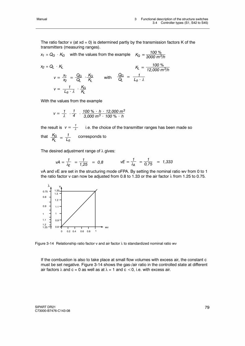
3 Functional description of the structure switches3.4 Controller types (S1, S42 to S45)
Manual
SIPART DR21C73000-B7476-C143-08
79
The ratio factor v (at xd = 0) is determined partly by the transmission factors K of thetransmitters (measuring ranges).
x1 = QG ⋅ KG with the values from the example 100 %3000 m3/hKG =
x2 = QL ⋅ KL 100 %12,000 m3/hKL =
v = = QGQL
x1x2
⋅ withQGQL
1L ⋅ λ
=
v = 1L ⋅ λ
KGKL
KGKL
⋅
With the values from the example
v = 1λ ⋅
14
100 % ⋅ h ⋅ 12,000 m33,000 m3 ⋅ 100 % ⋅ h⋅
the result is v = 1λ i.e. the choice of the transmitter ranges has been made so
that KGKL =
1L
corresponds to
The desired adjustment range of λ gives:
vA = =1λE
11,25 = 0,8 vE = =1
λA10,75 = 1,333
vA and vE are set in the structuring mode oFPA. By setting the nominal ratio wv from 0 to 1the ratio factor v can now be adjusted from 0.8 to 1.33 or the air factor λ from 1.25 to 0.75.
0.75
1.21.25 0.8
0.9
1
1.1
1.2
0.2 0.6
1.331.3
10.80.40
0.8
1.1
0.9
1
wv
vλ
Figure 3-14 Relationship ratio factor v and air factor λ to standardized nominal ratio wv
If the combustion is also to take place at small flow volumes with excess air, the constant cmust be set negative. Figure 3-14 shows the gas-/air ratio in the controlled state at differentair factors λ and c = 0 as well as at λ = 1 and c<0, i.e. with excess air.
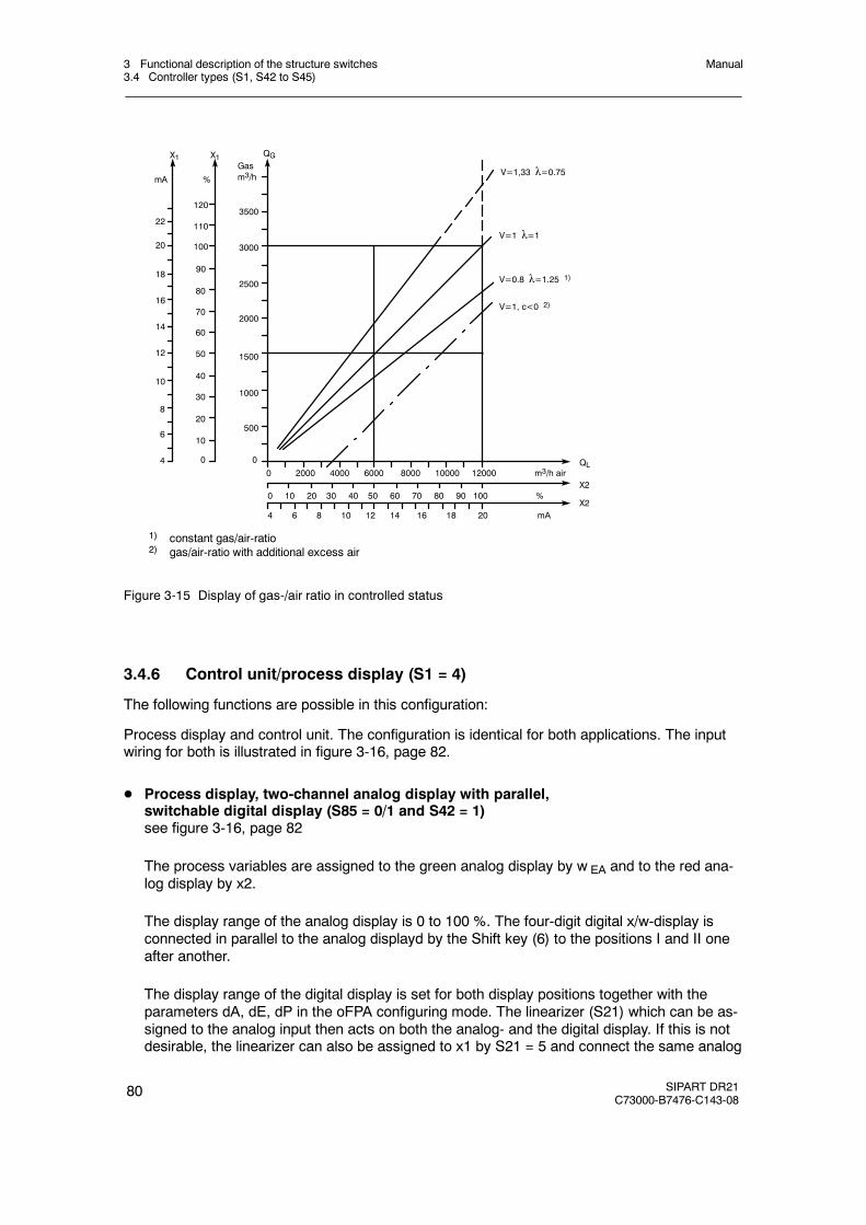
3 Functional description of the structure switches3.4 Controller types (S1, S42 to S45)
Manual
80 SIPART DR21C73000-B7476-C143-08
1) constant gas/air-ratio2) gas/air-ratio with additional excess air
%mAGasm3/h V=1,33 λ=0.75
0 2000 4000 6000 8000 10000 12000 m3/h airQL
V=1 λ=1
V=0.8 λ=1.25 1)
V=1, c<0 2)
X24 6 8 10 12 14 16 18 20 mA
X20 10 20 30 40 50 60 70 80 90 100 %
22
20
18
16
14
12
10
8
6
4
120
110
100
90
80
70
60
50
40
30
20
10
0
3500
3000
2500
2000
1500
1000
500
X1 X1 QG
0
Figure 3-15 Display of gas-/air ratio in controlled status
3.4.6 Control unit/process display (S1 = 4)
The following functions are possible in this configuration:
Process display and control unit. The configuration is identical for both applications. The inputwiring for both is illustrated in figure 3-16, page 82.
D Process display, two-channel analog display with parallel,switchable digital display (S85 = 0/1 and S42 = 1)see figure 3-16, page 82
The process variables are assigned to the green analog display by w EA and to the red ana-log display by x2.
The display range of the analog display is 0 to 100 %. The four-digit digital x/w-display isconnected in parallel to the analog displayd by the Shift key (6) to the positions I and II oneafter another.
The display range of the digital display is set for both display positions together with theparameters dA, dE, dP in the oFPA configuring mode. The linearizer (S21) which can be as-signed to the analog input then acts on both the analog- and the digital display. If this is notdesirable, the linearizer can also be assigned to x1 by S21 = 5 and connect the same analog
3 Functional description of the structure switches3.4 Controller types (S1, S42 to S45)
Manual
SIPART DR21C73000-B7476-C143-08
81
input (AI1 to AI4) by S15 (x1) and S16 (x2). In this case the unlinearized process variable isdisplayed in display order position II and the linearized process variable in position III.
Of course it is also possible to use the x1-display channel separately from the two analogdisplays as a third display channel.
Another display channel is available with the two-digit y-display via Y R.
D Process display, one-channel analog display with parallel,digital display and displayed limit valuessee fig. 3-16, page 82
The red analog display is fed via x2, a parallel physical digitual display is possible by assign-ing x1 via S15 to the same analog input if the linearizer is assigned to x1 by S21 = 5 and thedisplay range is set by dA, dE to oFPA-mode.
Of course it is also possible to use the x1-display channel separately from the two analogdisplays as a second display channel.
A third display channel is available with the two-digit y-display via yR.
Via S80 = 5/6 the limit values A1, A2 or A1 to A4 can be displayed on the green analog dis-play with a resultion of 3 %. When assigning the limit values to the displayed process vari-able in the red analog display, the position of the process variable to the limit values can beread. If a limit value responds, this is signaled by the corresponding alarm lamp (20) and theflashing alarm-LED on the green bargraph. The alarms can be labeled on the replaceablescale (21).
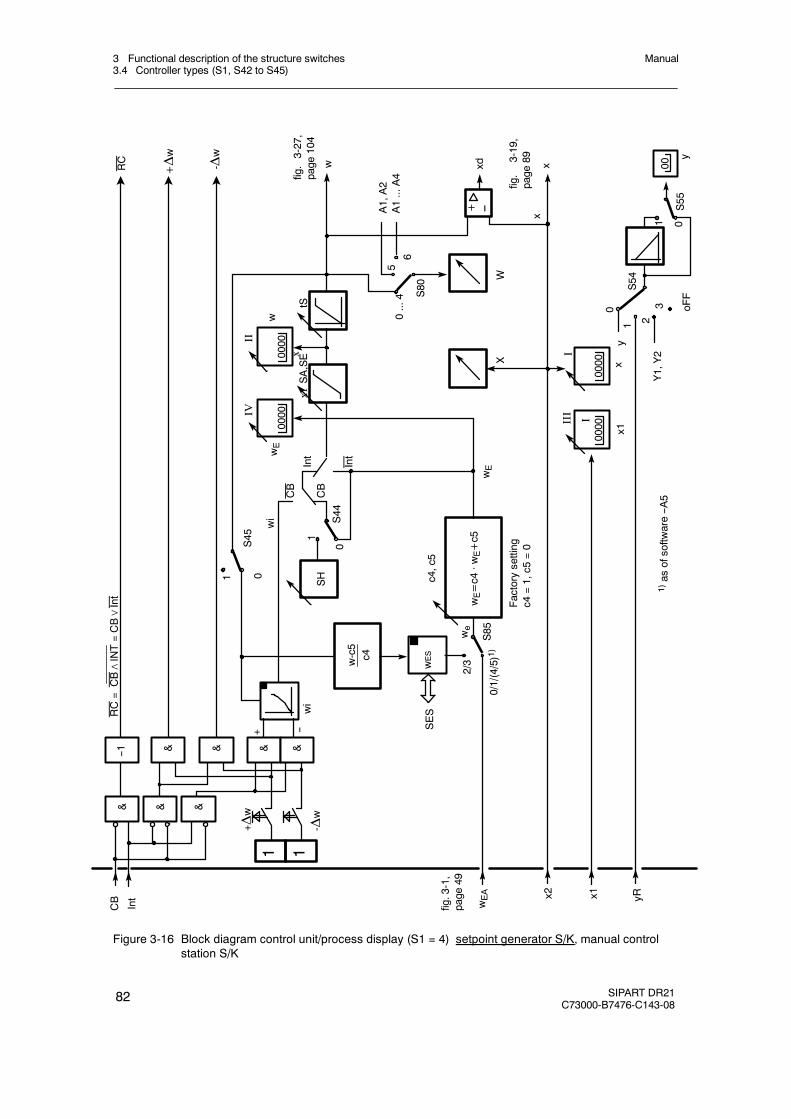
3 Functional description of the structure switches3.4 Controller types (S1, S42 to S45)
Manual
82 SIPART DR21C73000-B7476-C143-08
wEA
0
x2 yR
XW
wSH
w-c5
c4
xd
+ --
01
S45
wES
SES
2/3
c4,c5
wE=c4
·wE+c5
SA,SE
tS
x1
RC
+Δw
-Δw
x
1 0S55
0
1 23 oFF
Y1,Y2
x
wEInt
Int
CB
CB
S44
1
wE
0/1/(4/5)1)S85we
Factorysetting
c4=1,c5
=0
S54
RC=CB∧INT=CB∨Int
CB
Int
1 1-Δ
w
+ Δw
wi
wi
A1,A2
A1...A4
56
0...4 S80
y
w
1)as
ofsoftw
are--A
5
--+
&--1
& &
& & & &
0000
I0000III
I
x1x
0000
0000IV
II
x1x
00
y
fig.3-27,
page
104
fig.3-1,
page
49
fig.
3-19,
page
89
Figure 3-16 Block diagram control unit/process display (S1 = 4) setpoint generator S/K, manual controlstation S/K
3 Functional description of the structure switches3.4 Controller types (S1, S42 to S45)
Manual
SIPART DR21C73000-B7476-C143-08
83
D Control units
The integrated control unit function always includes a setpoint generator and a manualcontrol station in the following versions:
-- trackable K-setpoint generator-- S-setpoint generator-- trackable K-manual control station (S2 = 0)-- S-two-position control unit with 2 outputs (heating/cooling) (S2 = 1)-- S-three-position manual control unit internal feedback (S2 =2)-- S-three-position manual control unit external feedback (S2 =3)
The ability to combine setpoint generator- and manual control station type depends on theapplication. Either the setpoint generator or the manual control station can use the K-output,the remaining function must have an S-output.
- Setpoint generator see figure 3-16, page 82
S- and K-setpoint generators are installed parallel. In the S-setpoint generator, theswitching outputs±Δw can be locked depending on the Internal key (16) and the controlsignal CB, the status message is output by the signal lamps Int and C, see table 3-7,page 71. The feedback of the setpoint adjusted incrementally by the switching outputstakes place via the w-display (input w EA, the switching is blocked in position Ext, S42 =1).
In the K-setpoint generator the tracking of the internal setpoint is controlled dependent onthe Internal key (16) and the control signal CB, see table 3-7, page71. The tracking vari-able is fed in via w EA. The active setpoint is output by assignment of w to the analog out-put AO (S56 = 2/3).
With the Shift key (6) the digital x/w-display can be switched between the display levels Ito IV depending on the position of S81. The controlled variable is displayed in the displaylevel I. In display level II the active w can be displayed, in display level III the controlledvariable x1. The inactive setpoint is displayed in the display level IV. The displayed activeor external setpoint can also be adjusted (see table 3-11, page 84).
The active setpoint- and actual value is displayed on the analog displays.

3 Functional description of the structure switches3.4 Controller types (S1, S42 to S45)
Manual
84 SIPART DR21C73000-B7476-C143-08
Structureswitches
Posi-tion
Function
S81 Switching the w/x-digital displayDisplay order
I II III IV[0] x/xv w/wv -- --1 x/xv w/wv x1/xv --2 x/xv w/wi1/wv -- wE/wvE/wi23 x/xv w/wi1/wv x1/xv wE/wvE/wi2
4 x/xv -- -- --5 -- w/wv -- --6 -- -- x1/xv --7 xv wv x1 w
Identification of the displayed variables by the w- or x-signal lamp:1 = steady light, 0.5 = flashing light, 0 = off
Display orderI II III IV
1 0 0.5 (0 at S81=6) 0 x-signal lamp0 1 0 0,5 w-signal lamp
Table 3-11 Display levels (S81)
Control signals Message signalsEffect of the wired or
Digitalin-puts Front Front Digital outputs
active w atEffect of the±Δw-keys on
wired orInt∨CB
CB1) Inter-nal
Inter-nalLED
CLED
RB RC5)
S44=0 S44=1 wi ±Δw/BA
0 0 0 1 0 1 3) we(n)2) 3) we(n)2) no yes 07)
1 0 0 0 0 1 3) we(n)2) 3) we(n)2) no no 1
0 1 1 1 1 0 3) wi(n,↗) 3) wi(n,↗) yes no 1
16) 16) 16) 06) 16) 16) 3) we(n)2)6) SH4)6) no6) no6) 16)
1) The table is shown for static CB-switching without acknowledgement (S41 = 0).2) Source for wE at S85 = 0, 1, (4, 5 as of software version -A5), is wEA, which is assigned by S17 or at S85 = 2, 3 wES,
which is fed in via the SES.3) Tracking only takes place at S45=0 and only wES and wi to the active setpoint. When feeding in via wEA the feeding
instrument must be tracked.4) Only to be used as a flag pointer when no analog feedback is possible from the fed instrument.5) RC = no K-setpoint generator operation, wi not adjustable.6) Factory setting7) wired-or-connection of Int = RB and CB supplies Int∨CB
No S-setpoint optentiometer operation, Δw-keys not active(n) tracked to the value active before switching, therefore bumpless switching↗ adjustable
Table 3-12 Setpoint switching setpoint generator S/K, S1 = 4 process display/control unit
3 Functional description of the structure switches3.4 Controller types (S1, S42 to S45)
Manual
SIPART DR21C73000-B7476-C143-08
85
D Manual control station (S2 = 0, 1, 2, 3)
see figure 3-17, page 86 and figure 3-18, page 87
The controller output structures which can be configured by S2 are used for the manual con-trol station function whereby automatic operation is replaced by the ”Hold manipulated vari-able” mode. All other operating modes are identical with the controller functions. The lastmanipulated variable before switching to this operating mode is transferred to this hold oper-ation and theΔy-keys are inactive. If, in this operating mode, the manipulated variableoutput is to be tracked e.g. in 2-wait operation, the tracking operation must be activated bythe control signal N and the input yN.
If only manual control function without switching is desired, the instrument must be blockedin manual mode with S51 = 2.
The following figures only show 2 examples. For the other variations, see the block diagramsof the controller-output structures (fig. 3-22, page 96, figure 3-23, page 97 and figure 3-25,page 100 to figure 3-28, page 105).

3 Functional description of the structure switches3.4 Controller types (S1, S42 to S45)
Manual
86 SIPART DR21C73000-B7476-C143-08
-Δy
y R0 1
+Δy
02,3
S54
1
S55
0 2S51
1
H
0
2S51
1
H
+Δy H
-Δy H
NSi
Si
y S>50
+yBL
-yBL
+y BL
-yBL
N+Δy
- Δy
S19
S57
S57
S29
S30
αE
yGND
y S≤50
rt 00 y An
0 0
00
11
01
0
0
0
Block diagrams for S49 = 0 and manual control station S with ext. feedback (S2=3) see controller output structuresfigure 3-27, page 104
Figure 3-17 Block diagram control unit/process display (S1 = 4) manual control station S with internalfeedback S2 = 2 (manual operation has priority over tracking S49 = 1)

3 Functional description of the structure switches3.4 Controller types (S1, S42 to S45)
Manual
SIPART DR21C73000-B7476-C143-08
87
S51
S54
21
S85
Y1 Y2N
+yBL
-yBL
oFF
2/3
0
2
0/1/(4/5)1)
1
1
0
0
0
0
S55
S52
N
Si
yn
A
ya
tP,tM(S2=0)
YA YE
YS
y S56
- Δy
S57
<>
S53
1/3
0/2
YA
YE
30 1
S2
tM,tA
tP,tE
+Δy
S57
1/3
0/2
S53
S18
S29
S30
S19
YAn
H
0/1 tM
2/3/(4/5)1)
S85
1)as
ofsoftw
areversion--A
52)as
ofsoftw
areversion--B
2
1
y R
y H
y N
y ES
y ES
y E y HES
SES
00
12/13
10/11
0/1
S56
2)
Block diagram for S49 = 0, see controller output structures figure 3-28, page 105
Figure 3-18 Block diagram control unit/process display (S1 = 4) manual control station with K-outputS2 = 0/two-position output S2 = 1 (manual operation has priority over tracking S49 = 1)
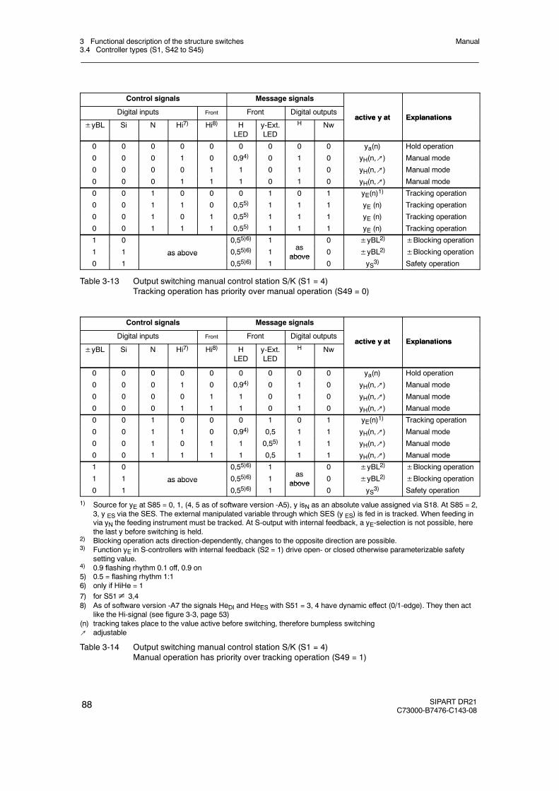
3 Functional description of the structure switches3.4 Controller types (S1, S42 to S45)
Manual
88 SIPART DR21C73000-B7476-C143-08
Control signals Message signals
Digital inputs Front Front Digital outputsactive y at Explanations
±yBL Si N Hi7) Hi8) HLED
y-Ext.LED
H Nwactive y at Explanations
0 0 0 0 0 0 0 0 0 ya(n) Hold operation
0 0 0 1 0 0,94) 0 1 0 yH(n,↗) Manual mode
0 0 0 0 1 1 0 1 0 yH(n,↗) Manual mode
0 0 0 1 1 1 0 1 0 yH(n,↗) Manual mode
0 0 1 0 0 0 1 0 1 yE(n)1) Tracking operation
0 0 1 1 0 0,55) 1 1 1 yE (n) Tracking operation
0 0 1 0 1 0,55) 1 1 1 yE (n) Tracking operation
0 0 1 1 1 0,55) 1 1 1 yE (n) Tracking operation
1 0 0,55)6) 1 0 ±yBL2) ±Blocking operation1 1 as above 0,55)6) 1
asabove
0 ±yBL2) ±Blocking operation0 1
as above0,55)6) 1
above0 yS3) Safety operation
Table 3-13 Output switching manual control station S/K (S1 = 4)Tracking operation has priority over manual operation (S49 = 0)
Control signals Message signals
Digital inputs Front Front Digital outputsactive y at Explanations
±yBL Si N Hi7) Hi8) HLED
y-Ext.LED
H Nwactive y at Explanations
0 0 0 0 0 0 0 0 0 ya(n) Hold operation
0 0 0 1 0 0,94) 0 1 0 yH(n,↗) Manual mode
0 0 0 0 1 1 0 1 0 yH(n,↗) Manual mode
0 0 0 1 1 1 0 1 0 yH(n,↗) Manual mode
0 0 1 0 0 0 1 0 1 yE(n)1) Tracking operation
0 0 1 1 0 0,94) 0,5 1 1 yH(n,↗) Manual mode
0 0 1 0 1 1 0,55) 1 1 yH(n,↗) Manual mode
0 0 1 1 1 1 0,5 1 1 yH(n,↗) Manual mode
1 0 0,55)6) 1 0 ±yBL2) ±Blocking operation1 1 as above 0,55)6) 1
asabove
0 ±yBL2) ±Blocking operation0 1
as above0,55)6) 1
above0 yS3) Safety operation
1) Source for yE at S85 = 0, 1, (4, 5 as of software version -A5), y isN as an absolute value assigned via S18. At S85 = 2,3, y ES via the SES. The external manipulated variable through which SES (y ES) is fed in is tracked. When feeding invia yN the feeding instrument must be tracked. At S-output with internal feedback, a yE-selection is not possible, herethe last y before switching is held.
2) Blocking operation acts direction-dependently, changes to the opposite direction are possible.3) Function yE in S-controllers with internal feedback (S2 = 1) drive open- or closed otherwise parameterizable safety
setting value.4) 0.9 flashing rhythm 0.1 off, 0.9 on5) 0.5 = flashing rhythm 1:16) only if HiHe = 17) for S51≠ 3,48) As of software version -A7 the signals HeDI and HeES with S51 = 3, 4 have dynamic effect (0/1-edge). They then act
like the Hi-signal (see figure 3-3, page 53)(n) tracking takes place to the value active before switching, therefore bumpless switching↗ adjustable
Table 3-14 Output switching manual control station S/K (S1 = 4)Manual operation has priority over tracking operation (S49 = 1)
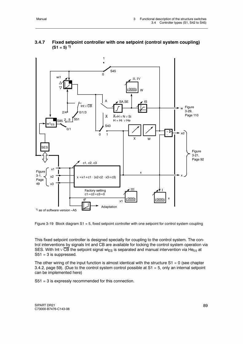
3 Functional description of the structure switches3.4 Controller types (S1, S42 to S45)
Manual
SIPART DR21C73000-B7476-C143-08
89
3.4.7 Fixed setpoint controller with one setpoint (control system coupling)(S1 = 5) 1)
tF
0
0
c1, c2, c3
x
1
S45
SA,SE
1
S43
Factory settingc1=c2=c3=0
x =x1+c1 · (x2-c2 · x3+c3)x2
x1
x3
xd
x
II, IV
W
A
Adaptation
tS
wi1
no
x1
w
0/1
2...5
2/4 0/1/3
S51
1) as of software version --A5
I
w1ES
SES
S85
Int∨CB
A A=H∨N∨SiH = Hi∨He
0000
X W
+--
x
III
0000 0000
Figure3-29,Page 110
Figure3-21,Page 92
Figure3-1,Page49
Figure 3-19 Block diagram S1 = 5, fixed setpoint controller with one setpoint for control system coupling
This fixed setpoint controller is designed specially for coupling to the control system. The con-trol interventions by signals Int and CB are available for locking the control system operation viaSES. With Int∨CB the setpoint signal wiES is separated and manual intervention via HeES atS51 = 3 is suppressed.
The other wiring of the input function is almost identical with the structure S1 = 0 (see chapter3.4.2, page 59). (Due to the control system control possible at S1 = 5, only an internal setpointcan be implemented here)
S51 = 3 is expressly recommended for this connection.
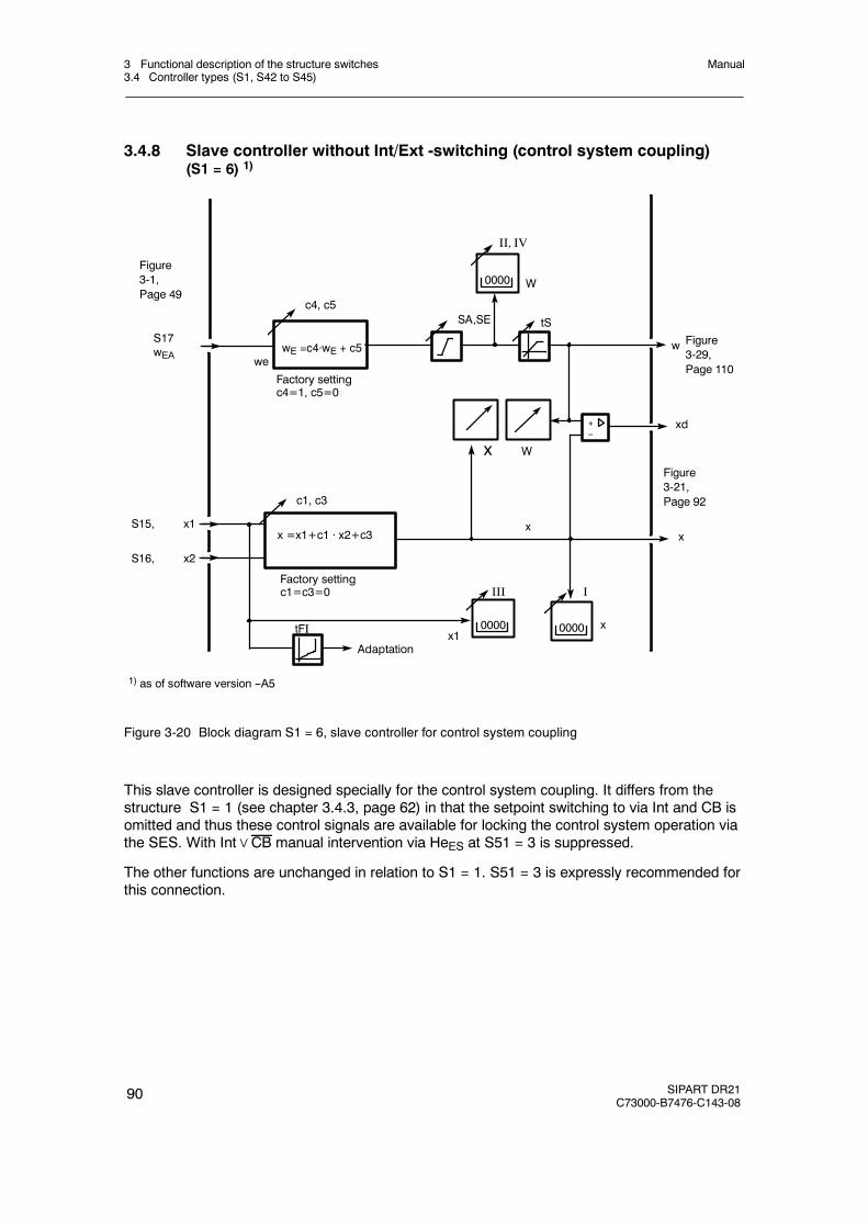
3 Functional description of the structure switches3.4 Controller types (S1, S42 to S45)
Manual
90 SIPART DR21C73000-B7476-C143-08
3.4.8 Slave controller without Int/Ext -switching (control system coupling)(S1 = 6) 1)
tFI
c1, c3
x
SA,SE
Factory settingc1=c3=0
x =x1+c1 · x2+c3S15, x1
xd
x
Adaptation
tS
x1
w
c4, c5
Factory settingc4=1, c5=0
wE =c4·wE + c5we
1) as of software version --A5
S16, x2
II, IV
W0000
Wx
+--
S17wEA
III
0000 0000
I
x
Figure3-29,Page 110
Figure3-21,Page 92
Figure3-1,Page 49
Figure 3-20 Block diagram S1 = 6, slave controller for control system coupling
This slave controller is designed specially for the control system coupling. It differs from thestructure S1 = 1 (see chapter 3.4.3, page 62) in that the setpoint switching to via Int and CB isomitted and thus these control signals are available for locking the control system operation viathe SES. With Int∨CB manual intervention via HeES at S51 = 3 is suppressed.
The other functions are unchanged in relation to S1 = 1. S51 = 3 is expressly recommended forthis connection.
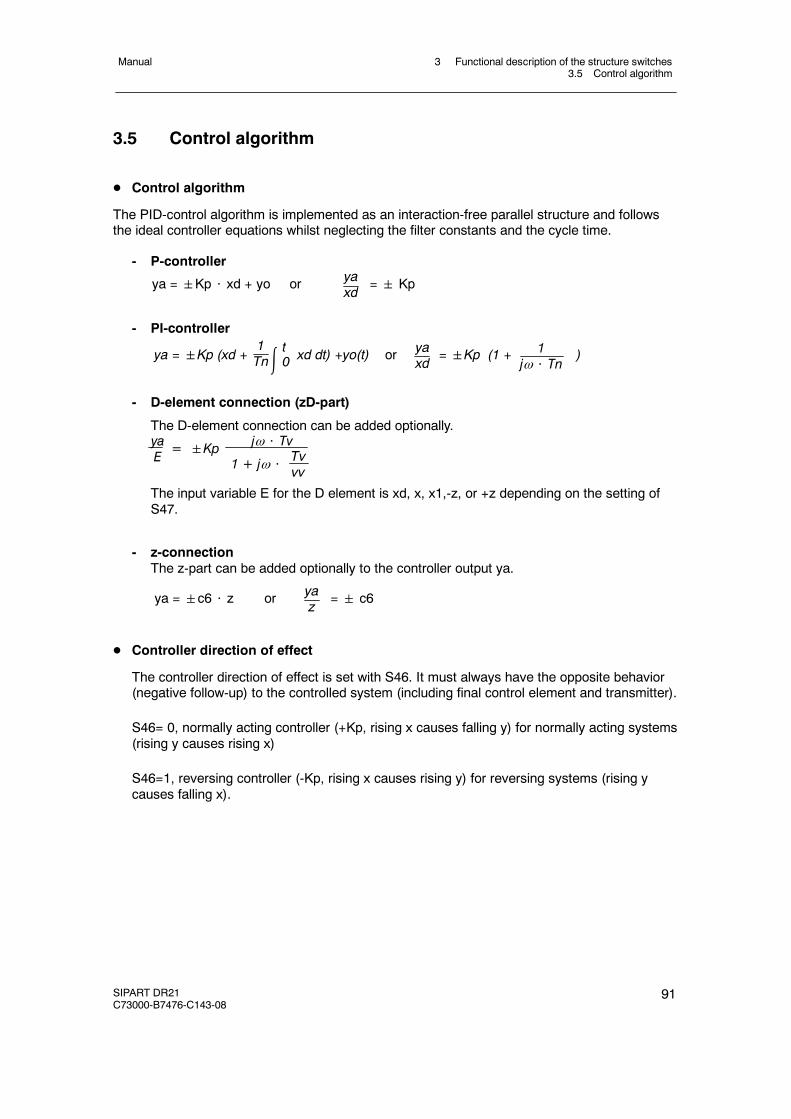
3 Functional description of the structure switches3.5 Control algorithm
Manual
SIPART DR21C73000-B7476-C143-08
91
3.5 Control algorithm
D Control algorithm
The PID-control algorithm is implemented as an interaction-free parallel structure and followsthe ideal controller equations whilst neglecting the filter constants and the cycle time.
- P-controller
ya =Kp ⋅ xd + yo or yaxd
= Kp
- PI-controller
ya =Kp (xd + xd dt) +yo(t) or =Kp (1 + )1Tn t0 ya
xd1
j ⋅ Tn
- D-element connection (zD-part)
The D-element connection can be added optionally.yaE Tv
vv
= Kp j ⋅ Tv
1 + j ⋅
The input variable E for the D element is xd, x, x1,-z, or +z depending on the setting ofS47.
- z-connectionThe z-part can be added optionally to the controller output ya.
ya =c6 ⋅ z or yaz
= c6
D Controller direction of effect
The controller direction of effect is set with S46. It must always have the opposite behavior(negative follow-up) to the controlled system (including final control element and transmitter).
S46= 0, normally acting controller (+Kp, rising x causes falling y) for normally acting systems(rising y causes rising x)
S46=1, reversing controller (-Kp, rising x causes rising y) for reversing systems (rising ycauses falling x).
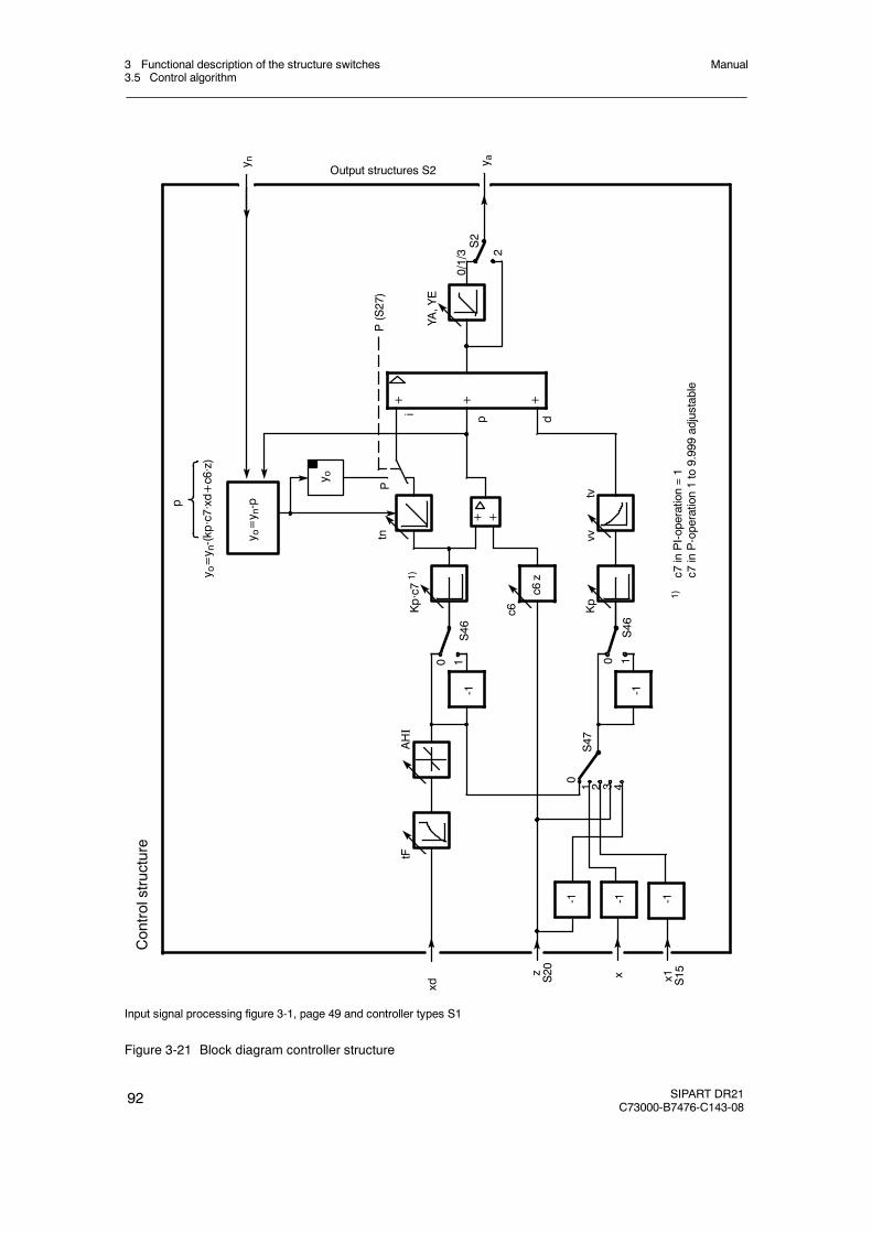
3 Functional description of the structure switches3.5 Control algorithm
Manual
92 SIPART DR21C73000-B7476-C143-08
z S20 x1 S15x
2
y n y a
S47
c6Kp·c71)
i
Ptn
S2
P(S27)
Kp
S46
S46
0
AHI
tF
0/1/3
0 10 1
+ + +
-1
c6z
y o
YA,YE
y o=y n-(kp·c7·xd+c6·z)
Controlstructure
1 2 3 4
xd
p
1)c7
inPI-operation=1
c7inP-operation1to9.999adjustable
-1 -1 -1
-1
vvtv
+
Output structures S2
+p d
y o=y n-p
Input signal processing figure 3-1, page 49 and controller types S1
Figure 3-21 Block diagram controller structure
3 Functional description of the structure switches3.5 Control algorithm
Manual
SIPART DR21C73000-B7476-C143-08
93
D Operating point yo for P-controllers
The operating point yo of the P-controller can be set either automatically or as a parameter(onPA).
Automatic working point (Yo = Auto)
Whenever there is no automatic operation (manual-, tracking-, safety- or blocking operation)the operating point yo is tracked so that switching to automatic operation is bumpless.This gives an automatic setting of the operating point yo in manual mode:
yo = yH - (Kp · c7 · (w - xH) + c6 · z)
If the actual value in manual mode (xH) is driven to the desired setpoint w by the appropriatemanual manipulated variable yH, the operating point yo is identical to the manual manipu-lated variable yH.
yo = yH or yo = yH + c6 · z.
Fixed working point (Yo = 0 to 100 %)
The controller operates in all operating modes with the working point set as a permanentparameter.
D manipulated variable limit YA, YE
The manipulated variable limit with the parameters YA and YE is only active in automaticoperation or in all operating modes depending on the switch position of S53. The limits ofthese parameters are at -10 and +110 %. However, it should be taken into account that thecontroller neither outputs negative actuating currents nor detects any negative position feed-back signals.
If the manipulated variable ya reaches one of the limits YA or YE in the limited operatingmode, further integration is aborted to avoid integral saturation. This ensures that themanipulated variable can be changed immediately after reversing the polarity.
In manual-, tracking-(DDC) or safety operation, the manipulated variable y at S53 = 0 (limit-ing only in automatic operation) can be driven out of the limiting range. When switching toautomatic operation the last manipulated variable is then transferred bumplessly but onlychanges in the manipulated variable in the direction of the YA to YE range are subsequentlyexecuted.
The manipulated variable limiting is possible at K-, two-position-and three-position-stepper-controllers with external position feedback (S2 = 0, 1, 3).
3 Functional description of the structure switches3.6 Controller output structures (S2, S49 to S55)
Manual
94 SIPART DR21C73000-B7476-C143-08
D Bumpless switching to automatic mode
If there is no automatic operation (manual-, tracking, safety- or active blocking operation) theI-part or the operating point yo (only at Yo = Auto) is tracked so that the switching to auto-matic operation is bumpless. Any still active D-part is set to zero.
D P-PI-switching
With the control signal P = 1, the controller is switched from PI-to P-behavior, at Yo = Auto,the switching is bumpless.
3.6 Controller output structures (S2, S49 to S55)
The controller structures follow four different controller output structures depending on structureswitch S2.
S2=0 K-controllerS2=1 Two-position controller with 2 S-outputs heating/cooling, optionally one K-outputS2=2 S-controller with internal feedbackS2=3 S-controller with external feedback
D S2=0: continuous (K) controller (figure 3-22, page 96 and figure 3-23, page 97)
To control proportional active actuators (e.g. pneumatic actuators or I/P-transformers) or ascommand controllers in cascades.
actuating time tP,tM (onPA)
The setting speed of the automatic manipulated variable is set with the parameters tP andtM. In the oFF position, no limiting takes place, in positions 1 to 1000 s the minimumactuating time for 0 to 100 % manipulated variable is preset. Whereby tP acts during in-crease and tM during decrease of the manipulated variable. The P-, I- and D-part as well asthe disturbance variable z is limited in the rise speed.This setting speed limit is used:
- to avoid integral saturations in the actuating times of the following actuator>1 s- to avoid hard output surges of the P-, D- and z-part.
In this case it must be taken into account that the control time is greater.

3 Functional description of the structure switches3.6 Controller output structures (S2, S49 to S55)
Manual
SIPART DR21C73000-B7476-C143-08
95
D S2 = 1: two-position controller, with 2 S-outputs heating/cooling;optionally one K-output
This output structure is identical to the K-output structure in its switching options (see figure3-22, page96 and figure 3-23, page97).
The controller can be operated exclusively as a two-position controller (both outputs asswitching outputs) or as a controller with one K-output and one switching output.
The output variable can only adopt two states for every switching output + Δy, -Δy. Switchingon or switching off. The relationship between switching on- and switching off is defined as
setting ratio =switch-on duration
switch-on duration + switch-off duration
Switch on duration and switch off duration together give the period duration.
The setting range y from 0 to 100 % can be divided into two sub-ranges. The range Y1 witha falling characteristic for cooling, the range 100% Y2 with rising characteristic for heating.Two pulse stages are connected in series which transform the two sub manipulated vari-ables into pulse-pause ratio. It is possible to use the manipulated variable limiting of y withthe parameters yA and yE, the setting ratio 1 is then not reached. Since the minimum pulseduration or -pause can be set by tA or tE, further limiting is not normally necessary. A deadzone can bset between these two sub manipulated variables. By changing Y1 or Y2 (oFPA)the dead zone is preset and the slope adapted to the cooling- or heating aggregate.
Factory setting Y1 = Y2 = 50 % corresponds to dead zone = 0 %.
Every sub manipulated variable can be assigned a different period duration tP and tM(onPA). In every chapter the setting ratio 0 to 1 is run through, whereby the shortest switchon- or switch off duration is set with tE and tA (onPA). The period duration must be set sothat the respective best compromise between the minimum permissible switch on duration ofthe actuator (e.g. contactor, solenoid valve, fan, cooling compressor), the switching fre-quency and the resulting curve of the controller variable is found.
With structure switch S56 one of the outputs Y1 and Y2 can be switched to the analogoutput (as of software version --B2).
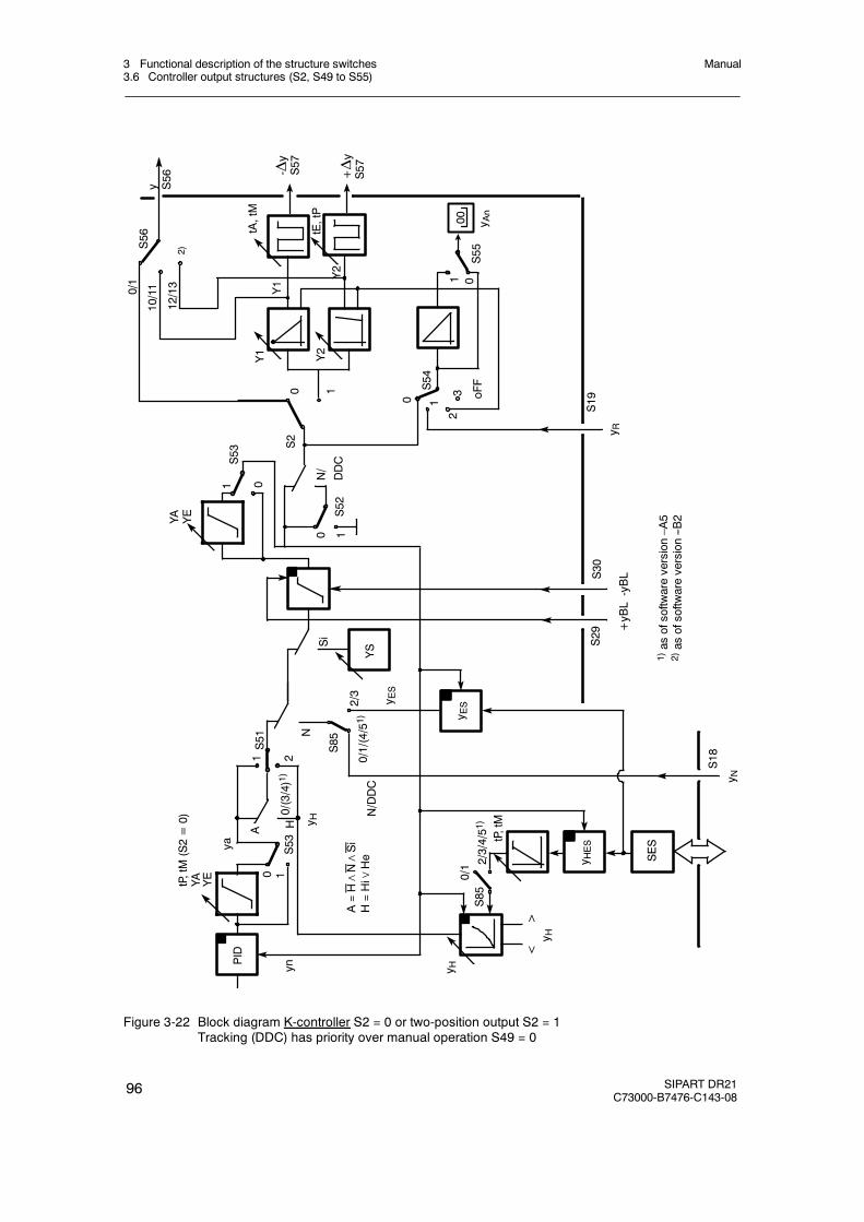
3 Functional description of the structure switches3.6 Controller output structures (S2, S49 to S55)
Manual
96 SIPART DR21C73000-B7476-C143-08
N/DDC
tE,tP
tA,tM
S51
S54
2
1
S85
Y1 Y2
+yBL-yBL
oFF
2/3
2 0/1/(4/51)
1
1
1
0
0
0
S55
S52
NSi
yn
A
ya
tP,tM(S2=0)
YA YE
H
YS
-Δy
S57
S53
10
YA YE
30 1
S2
+Δy
S57
1 0
S53
S29
S30
S19
PID
0/(3/4)1)
<>
S18
SES
0/1 2/3/4/51
)S85
tP,tM
1)as
ofsoftw
areversion–A
52)as
ofsoftw
areversion--B
2
N/DDC
y R
y N
y H
y H
A=H∧N∧Si
H=Hi∨
He
y H
y ES
y HES
00 y An
y ES
y S56
12/13
10/110/1
S56
Y1
Y2
2)
Figure 3-22 Block diagram K-controller S2 = 0 or two-position output S2 = 1Tracking (DDC) has priority over manual operation S49 = 0
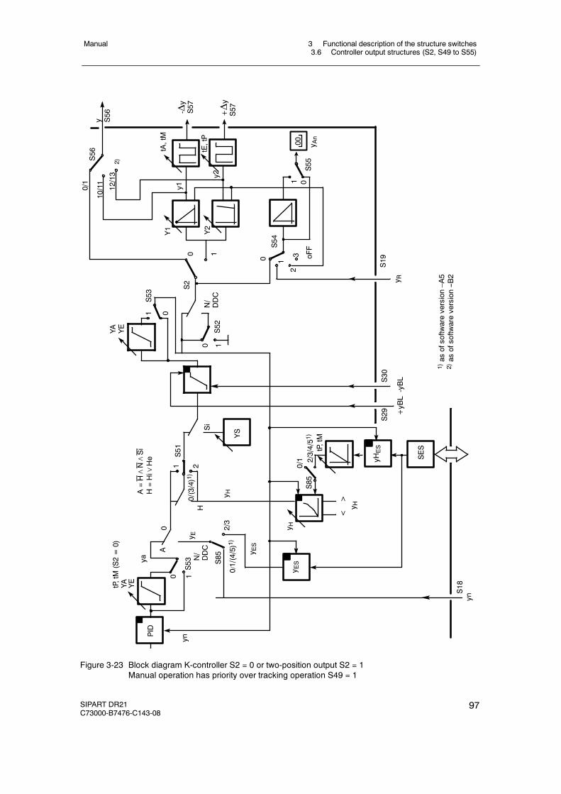
3 Functional description of the structure switches3.6 Controller output structures (S2, S49 to S55)
Manual
SIPART DR21C73000-B7476-C143-08
97
N/DDC
N/DDC
S29
S51
S85
+yBL-yBL
2/3
0
2
0/1/(4/5)1)
1
1
0
S52
Si
yn
A
ya
tP,tM(S2=0)
YA YE
YS
S53
10
YA YE
1 0
S53
S30
0/(3/4)1)
<>
SES
0/1 2/3/4/51
)S85
tP,tM
S18
HtE,tP
tA,tM
S54
2
1
Y1 Y2
oFF
1 0
0
S55
-Δy
S57
30 1+Δy
S57
S19
y1
y2
y R
00 y An
yHES
PID
y H
y H
y E
y ES
y HA=H∧N∧Si
H=Hi∨
He
y ES
yn
y S56
12/13
10/11
0/1
S56
S2
1)as
ofsoftw
areversion–A
52)as
ofsoftw
areversion--B
2
2)
Figure 3-23 Block diagram K-controller S2 = 0 or two-position output S2 = 1Manual operation has priority over tracking operation S49 = 1
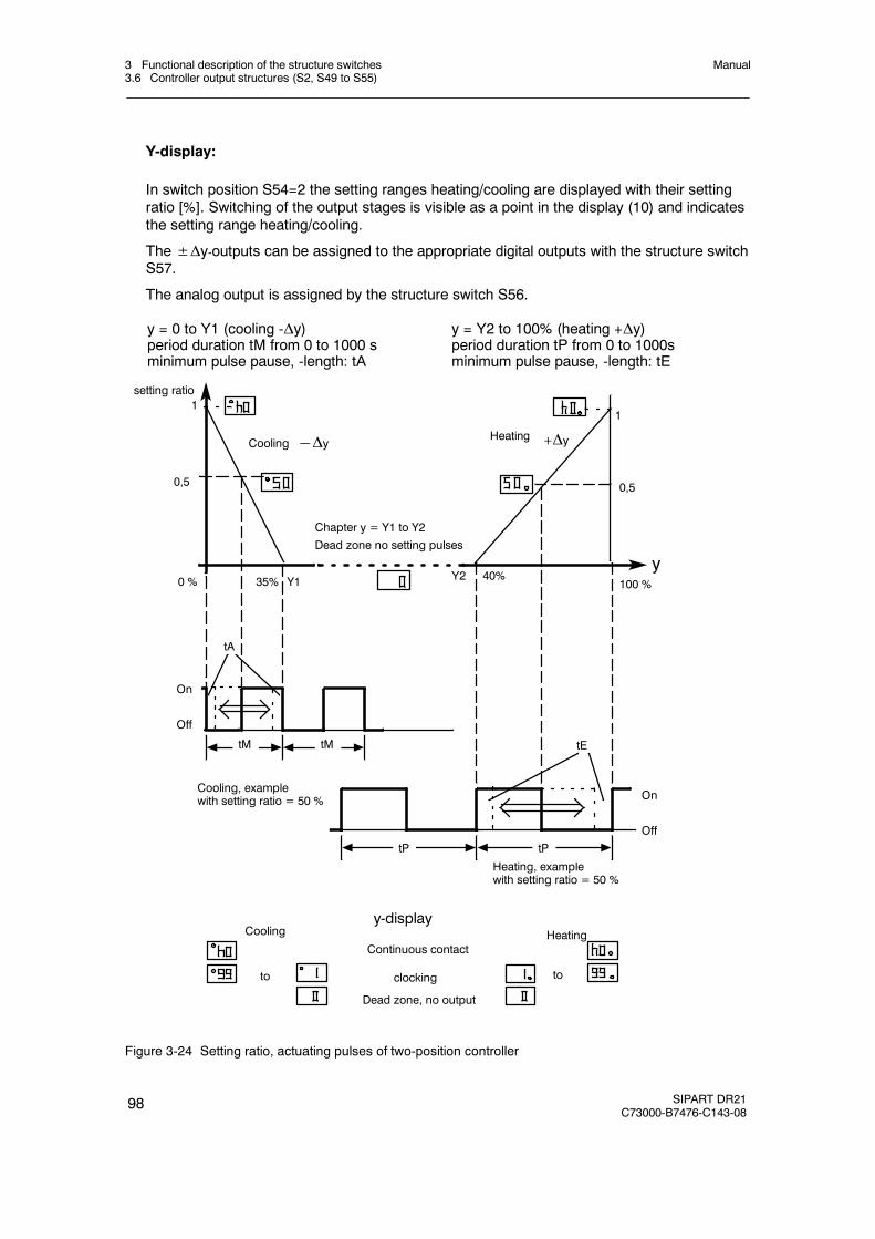
3 Functional description of the structure switches3.6 Controller output structures (S2, S49 to S55)
Manual
98 SIPART DR21C73000-B7476-C143-08
Y-display:
In switch position S54=2 the setting ranges heating/cooling are displayed with their settingratio [%]. Switching of the output stages is visible as a point in the display (10) and indicatesthe setting range heating/cooling.
The±Δy-outputs can be assigned to the appropriate digital outputs with the structure switchS57.
The analog output is assigned by the structure switch S56.
y = 0 to Y1 (cooling -Δy)period duration tM from 0 to 1000 sminimum pulse pause, -length: tA
y = Y2 to 100% (heating +Δy)period duration tP from 0 to 1000sminimum pulse pause, -length: tE
setting ratio
y
11
0,5 0,5
100 %40%0 %
+Δy―Δy
Y1
Heating
35% Y2
Chapter y = Y1 to Y2Dead zone no setting pulses
tA
tE
On
Off
On
Off
tM tM
tP tP
Cooling, examplewith setting ratio = 50 %
Heating, examplewith setting ratio = 50 %
Cooling
y-display
Continuous contact
clocking
Dead zone, no output
Cooling Heating
to to
Figure 3-24 Setting ratio, actuating pulses of two-position controller
3 Functional description of the structure switches3.6 Controller output structures (S2, S49 to S55)
Manual
SIPART DR21C73000-B7476-C143-08
99
D S2 = 2: Three-position step controller (S) with internal feedback
see figure 3-25, page 100 and figure 3-26, page 101
To control I-acting motorized actuating drives.
In S-controllers with internal feedback the K-controller is followed by an internal position con-troller. The positioning control circuit consists of a comparator with following three-positionswitch with hysteresis and an integrator in the feedback. The I-function of the actuator issimulated by the integrator with adjustable actuating time tY (parameterization mode onPA)which replaces the position feedback. To ensure the internal integrator and the K-controlleroutput do not drift apart or into saturation in time, both are set back rhythmically by the sameamount (synchronized). The y-output is only a relative manipulated variable. It is thereforenot possible to perform a manipulated variable limiting of YA and an absolute value preset ofYE und YS. The safety manipulated variable YS is specified as a direction-dependent con-tinuous contact. At YS≤50 % (oFPA) -Δy switches, at YS > 50 %, +Δy switches to continu-ous contact so that the end positions of the actuator represent the safety position. The posi-tion controller has an adjustable minimum pulse length (tE) and-pause (tA) with which theresponse threshold of the position controller is set indirectly:
- Switching on Aee = 2 100 % ⋅ tEtY
- Switching off Aea = 100 % ⋅ tEtY
- Hysteresis Aee -- Aea = 100 % ⋅ tEtY
- Pause Aa = 100 % ⋅ tAtY
- tY = tP, tM set actuating time (parameterization mode onPA)
Aee must be set up after a pulse pause at least as a deviation until an actuating pulse withlength tE is output. Aea can remain as a constant control error of the position control circuit.
Aa can be set up after an actuating pulse as a deviation until an actuating pulse is output inthe same or opposite direction. When time tA has expired, the position controller reactsaccordingly to the set tE.
Setting criteria of tA and tE, see chapter 6.3, page 183.
The position feedback yR is only used to display the manipulated variable in S-controllerswith internal feedback. If it is not connected, S54 is set to 3, the y-display (9) is then dark.

3 Functional description of the structure switches3.6 Controller output structures (S2, S49 to S55)
Manual
100 SIPART DR21C73000-B7476-C143-08
1
02,3
S54
1
S55
2
S51
1
H
2S51
1
H
+Δy H
-Δy H
N
N
Si
Siy S>50
+yBL
-yBL
+ -PID
+ -
tP,tM
tA,tE
internalpositioncontrolcircuit
+ΔY a
yn
ya
0/(3/4)*
S30
S29
*asofsoftwareversion–A5
0/(3/4)*
y S≤50
- Δy
y R+Δy
S19
S57
S57
μE
yGND
0
YAn
00
A=H∧N∧Si
H=Hi∨
He
11
10
00
0
0
Figure 3-25 Block diagramS-controller with internal feedback S2 =2Tracking (DDC) has priority over manual operation S49 = 0
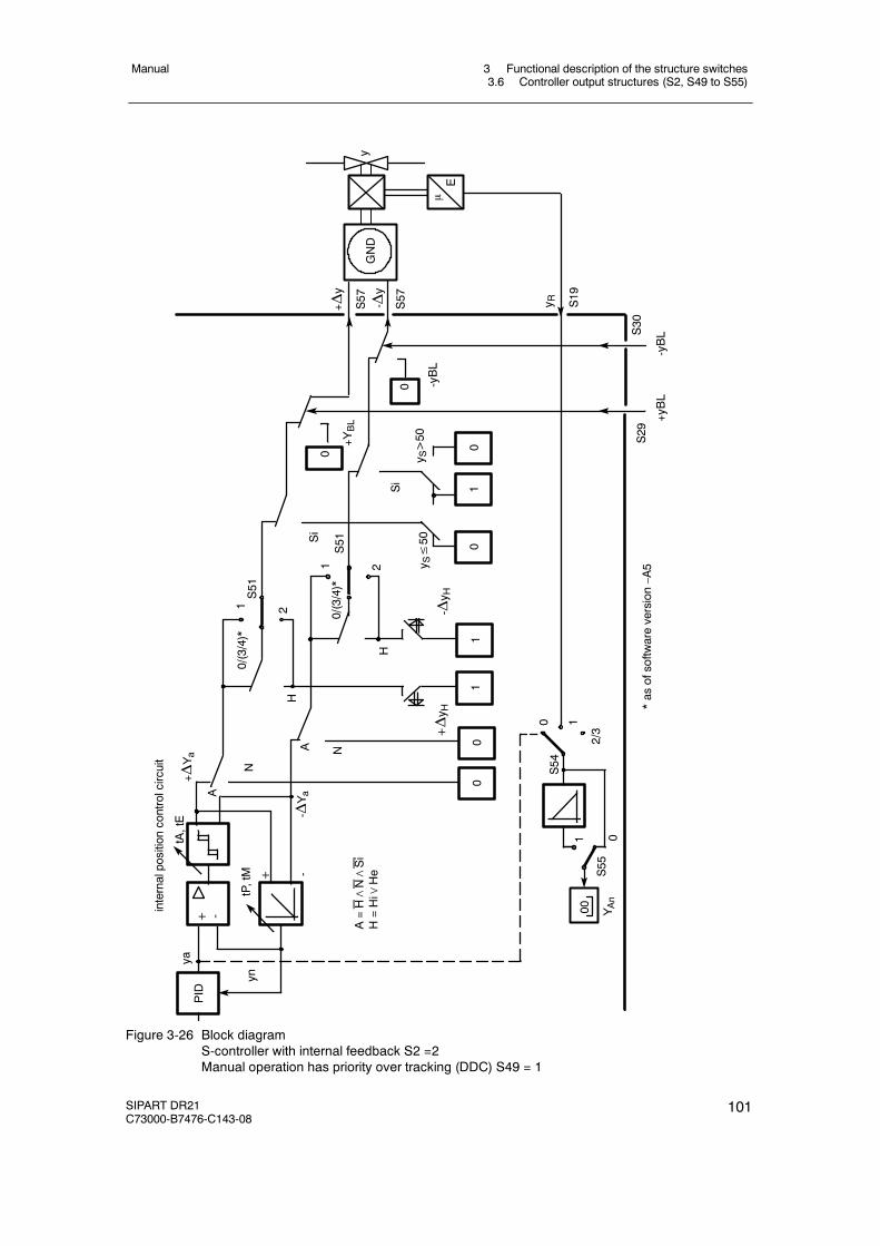
3 Functional description of the structure switches3.6 Controller output structures (S2, S49 to S55)
Manual
SIPART DR21C73000-B7476-C143-08
101
0 1
02/3
S54
1
S55
2
S51
0
00
0
1
A
2
S51
1
H
+Δy H
-Δy H
N
N
Si
Si
+ -
+ -
tP,tM
tA,tE
internalpositioncontrolcircuit
+ ΔYa
A- Δ
Ya
H
+YBL
yn
ya
0/(3/4)*
S29
*asofsoftwareversion–A5
0/(3/4)*
0
S30
-Δy
y R+Δy
S19
S57
S57
μE
yGND
PID
00 YAn
y S>50
y S≤50
A=H∧N∧Si
H=Hi∨
He
+yBL
-yBL
01
11
-yBL
Figure 3-26 Block diagramS-controller with internal feedback S2 =2Manual operation has priority over tracking (DDC) S49 = 1
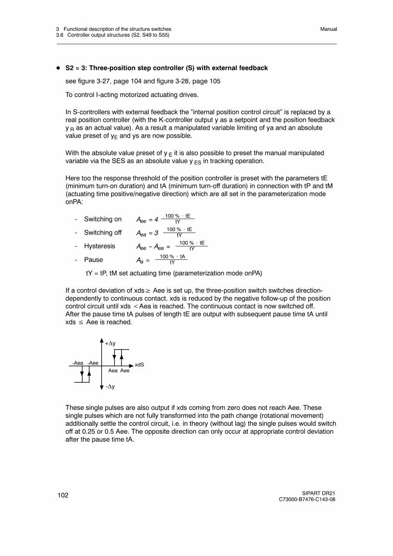
3 Functional description of the structure switches3.6 Controller output structures (S2, S49 to S55)
Manual
102 SIPART DR21C73000-B7476-C143-08
D S2 = 3: Three-position step controller (S) with external feedback
see figure 3-27, page 104 and figure 3-28, page 105
To control I-acting motorized actuating drives.
In S-controllers with external feedback the ”internal position control circuit” is replaced by areal position controller (with the K-controller output y as a setpoint and the position feedbacky R as an actual value). As a result a manipulated variable limiting of ya and an absolutevalue preset of yE and ys are now possible.
With the absolute value preset of y E it is also possible to preset the manual manipulatedvariable via the SES as an absolute value y ES in tracking operation.
Here too the response threshold of the position controller is preset with the parameters tE(minimum turn-on duration) and tA (minimum turn-off duration) in connection with tP and tM(actuating time positive/negative direction) which are all set in the parameterization modeonPA:
- Switching on Aee = 4100 % ⋅ tE
tY
- Switching off Aea = 3100 % ⋅ tE
tY
- Hysteresis Aee -- Aea =100 % ⋅ tE
tY
- Pause Aa =100 % ⋅ tA
tY
tY = tP, tM set actuating time (parameterization mode onPA)
If a control deviation of xds≥ Aee is set up, the three-position switch switches direction-dependently to continuous contact. xds is reduced by the negative follow-up of the positioncontrol circuit until xds<Aea is reached. The continuous contact is now switched off.After the pause time tA pulses of length tE are output with subsequent pause time tA untilxds≤ Aee is reached.
-Aea -AeeAea Aee
-Δy
+Δy
xdS
These single pulses are also output if xds coming from zero does not reach Aee. Thesesingle pulses which are not fully transformed into the path change (rotational movement)additionally settle the control circuit, i.e. in theory (without lag) the single pulses would switchoff at 0.25 or 0.5 Aee. The opposite direction can only occur at appropriate control deviationafter the pause time tA.
3 Functional description of the structure switches3.6 Controller output structures (S2, S49 to S55)
Manual
SIPART DR21C73000-B7476-C143-08
103
The manual adjustment is made as an incremental adjustment by far overranging of thethree-position switch so that manual adjustment is also possible when the position feedbackis interrupted. (Only at S54=1 or 3)
To simplify commissioning of the position control circuit, the manual manipulated variable ispreset absolutely at S54=0 (manipulated variable of the K-controller) so that the setpoint ofthe position control circuit is changed continuously by the manual manipulated variable inthis structure switch position to enable optimization (see chapter 6.2, page 183 ). It shouldbe taken into account here that the manual manipulated variable which is also displayed ischanged faster by the actuating time tY than the active manipulated variable on the actuatorand a lag therefore takes place. The controlling status can be monitored on the Δy-LEDs (9)in the y-display. After optimization, S54 should be set to 1 to display the active manipulatedvariable via the position feedback yR.

3 Functional description of the structure switches3.6 Controller output structures (S2, S49 to S55)
Manual
104 SIPART DR21C73000-B7476-C143-08
Si
0/1
2/3
YA
0,1
tP,tM
SES
<
YE
PID
12
S51
H
ya
yS
y ESy E
S
y EN/DDC
yHES
y H
& &
S57
--yBL
+yBL
μE
--Δy
+Δy
y
S19
y R
2,3,4,5
S85
y H
y Ny H
y
2,31
0S54
01
S55
00 y AN
externalpositioncontrolcircuit
y
--+
y N
S18
0
S53
0/(3/4)*
1
(4/5)*
S85
y N
1 0S53
YA YE
S29
S30
S57
GND
tP,tM
tA tE
*as
ofsoftw
areversion-A5
Figure 3-27 Block diagram S-controller with external feedback S2 =3Tracking (DDC) has priority over manual operation S49 = 0
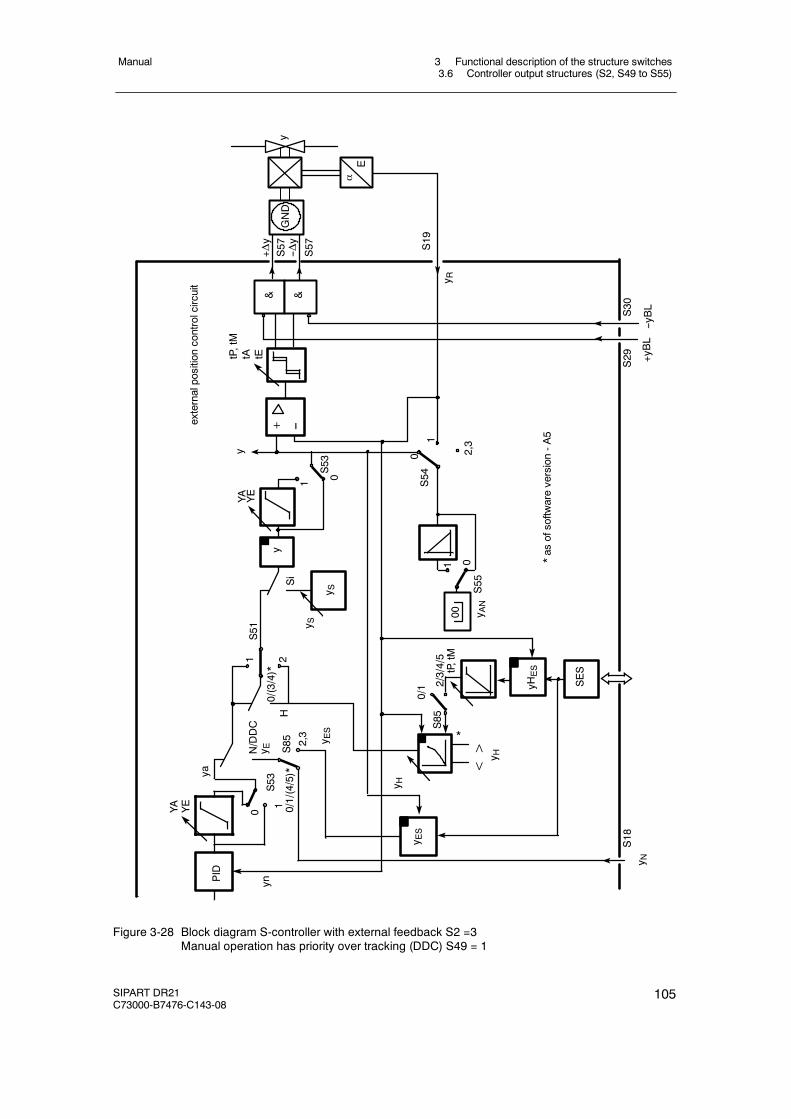
3 Functional description of the structure switches3.6 Controller output structures (S2, S49 to S55)
Manual
SIPART DR21C73000-B7476-C143-08
105
N/DDC
y ES51
0/(3/4)*
1
0 0/1/(4/5)*
2,3
yn1 2
ya
YA YE
PID
0/1 2/3/4/5
S85
S53
HSi
y S
& &
S57
--yBL
+yBL
αE
--Δy
+Δy
y
S19
y R
y
2,31
0S54
01
S55
00 y AN
externalpositioncontrolcircuit
y
--+
1 0S53
YA YE
S29
S30
S57
SES
yHES
<> y H
y ES
y H
y ES
tP,tM
tA tE
*as
ofsoftw
areversion-A5
y NS18
*
y S
S85
tP,tM
GND
Figure 3-28 Block diagram S-controller with external feedback S2 =3Manual operation has priority over tracking (DDC) S49 = 1
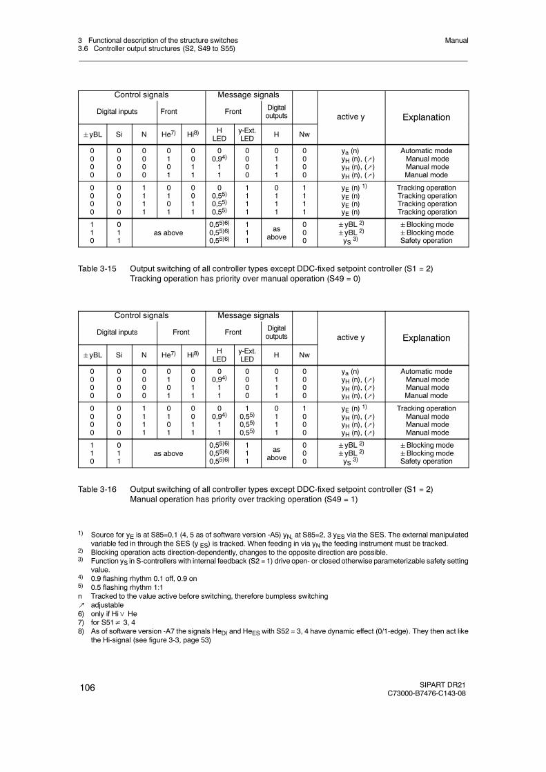
3 Functional description of the structure switches3.6 Controller output structures (S2, S49 to S55)
Manual
106 SIPART DR21C73000-B7476-C143-08
Control signals Message signals
Digital inputs Front Front Digitaloutputs active y Explanation
yBL Si N He7) Hi8) HLED
y-Ext.LED H Nw
y p
0000
0000
0000
0101
0011
00,94)11
0000
0111
0000
ya (n)yH (n), (↗)yH (n), (↗)yH (n), (↗)
Automatic modeManual modeManual modeManual mode
0000
0000
1111
0101
0011
00,55)0,55)0,55)
1111
0111
1111
yE (n) 1)yE (n)yE (n)yE (n)
Tracking operationTracking operationTracking operationTracking operation
110
011
as above0,55)6)0,55)6)0,55)6)
111
asabove
000
yBL 2)
yBL 2)
yS 3)
Blocking modeBlocking modeSafety operation
Table 3-15 Output switching of all controller types except DDC-fixed setpoint controller (S1 = 2)Tracking operation has priority over manual operation (S49 = 0)
Control signals Message signals
Digital inputs Front Front Digitaloutputs active y Explanation
yBL Si N He7) Hi8) HLED
y-Ext.LED H Nw
y p
0000
0000
0000
0101
0011
00,94)11
0000
0111
0000
ya (n)yH (n), (↗)yH (n), (↗)yH (n), (↗)
Automatic modeManual modeManual modeManual mode
0000
0000
1111
0101
0011
00,94)11
10,55)0,55)0,55)
0111
1000
yE (n) 1)yH (n), (↗)yH (n), (↗)yH (n), (↗)
Tracking operationManual modeManual modeManual mode
110
011
as above0,55)6)0,55)6)0,55)6)
111
asabove
000
yBL 2)
yBL 2)
yS 3)
Blocking modeBlocking modeSafety operation
Table 3-16 Output switching of all controller types except DDC-fixed setpoint controller (S1 = 2)Manual operation has priority over tracking operation (S49 = 1)
1) Source for yE is at S85=0,1 (4, 5 as of software version -A5) yN, at S85=2, 3 yES via the SES. The external manipulatedvariable fed in through the SES (y ES) is tracked. When feeding in via yN the feeding instrument must be tracked.
2) Blocking operation acts direction-dependently, changes to the opposite direction are possible.3) Function yS in S-controllers with internal feedback (S2 = 1) drive open- or closed otherwise parameterizable safety setting
value.4) 0.9 flashing rhythm 0.1 off, 0.9 on5) 0.5 flashing rhythm 1:1n Tracked to the value active before switching, therefore bumpless switching↗ adjustable6) only if Hi∨ He7) for S51≠ 3, 48) As of software version -A7 the signals HeDI and HeES with S52 = 3, 4 have dynamic effect (0/1-edge). They then act like
the Hi-signal (see figure 3-3, page 53)
3 Functional description of the structure switches3.6 Controller output structures (S2, S49 to S55)
Manual
SIPART DR21C73000-B7476-C143-08
107
D Automatic mode (y = ya)
The automatic mode is switched on with the Automatic/Manual key or in the case of dynamicswitching (S51= 3,4) 1) via He (yellow manual LED (8) off). All other control signals He, N(DDC), Si and±yBL must be 0. The automatic manipulated variable is connected through tothe controller output.
D Manual mode (y = yH)
Manual operation is switched on by the Automatic/Manual key (yellow manual LED(12) on)or the control signal He as an OR function. The control signal He acts statically in thestructure switch positions S51 = 0,1 static. At S51 = 3,4 it is dynamic, i.e. every positiveedge causes a switching process. The control signals Si and±yBL must be 0. If trackingoperation has priority over manual operation (S49=0), the control signal N (DDC) must alsobe 0. Otherwise tracking operation or safety- or blocking operation become active, themanual-LED then flashes in 0.5 rhythm as an identification. The manual manipulatedvariable is switched through to the controller output. The manual manipulated variable ispreset in K-controllers as an absolute value, in S-controllers as a positioning increment.
D Tracking-(DDC)-operation (y = yE)
The tracking operation is switched on by the control signal N (in DDC-mode by the controlsignal CB and the Internal/External, see chapter 3.4.4, page 68). The control signals Si and±yBL must be 0. If manual mode has priority over tracking mode (S49 = 1) the control sig-nal H = Hi∨He must be 0.
The external manipulated variable yE is connected through to the controller output. Thesource for yE at S85 = 0, 1,(4, 5 as of software version --A05), is preset as an absolutevalue y N. With S85 = 2, 3 the absolute value becomes active as an external manipulatedvariable via the SES (yES).
In S-controllers with internal feedback (S2 = 2), absolute value presets of the manipulatedvariable and thus the tracking operation are not possible.
D Safety operation (y = YS)
The safety operation is switched on by the control signal Si. The control signal±yBL mustbe 0. The safety manipulated variable YS is through connected which can be set as a para-meter in the structuring mode oFPA in the range from -10 to 110 %. In S-controllers with in-ternal feedback (S2 = 2) absolute value preset of the manipulated variable is not possible.When safety operation is active, at YS≤50 % -Δy continuous contact and at YS > 50 % +Δycontinous contact is output so that the actuator drives to the end positions.
1) as of software version - A05
3 Functional description of the structure switches3.6 Controller output structures (S2, S49 to S55)
Manual
108 SIPART DR21C73000-B7476-C143-08
D Direction-dependent blocking operation
Blocking operation is controlled by the control signals±yBL. All other control signals haveno function. If a control signal is applied the manipulated variable output is blocked direction-dependently, i.e. only changes in the opposite direction are allowed. If both control signalsare applied simultaneously, the output is blocked absolutely. The direction-dependent block-ing is necessary especially in S-controllers with internal feedback and actuators with limitstop switches to avoid integral saturation. If the control circuit is opened on reaching the endposition of the actuator, further integration of the controller must be prevented in order to beable to react immediately in the event of control difference reversal.
As described above, the control signals±yBL have priority over Si and H or N. Priority of Hor N can be selected via S49. All these operating modes have priority over automatic oper-ation.
Signaling of the switching states is made by the LEDs Manual (12) and y-external (13).When manual mode is active or preselected (if the priority opeating modes are active), themanual LED lights up. He = 1 is signaled by a flashing rhythm of 0.9 (control signal) if Hi =0 (i.e. is in automatic mode by the manual/automatic switching). When switching the controlsignal He from 1! 0 the automatic mode becomes active.
Tracking-(DDC), safety-and blocking operation is signaled by the y-External LED. Flashingrhythm 0.5 indicates that in ”manual operation priority over tracking operation”, manual oper-ation is active but tracking operation is prepared and after switching to automatic operationalso becomes active.
D Blocking of the manual/automatic switching (S51)
With S51 the manual/automatic switching can be blocked in the operating mode Automaticmode only or Manual mode only. The other operating modes are still possible. Then, trackingmode is only possible if tracking has priority over manual mode (see figure 3-22, page 96).
D Manual mode in the case of a transmitter fault (S50)
With S50 manual mode can be switched to when the transmitter group fault message occurs(see chapter 3.2, page 47). Manual operation starts at S50=1 with the last y or at S50 = 2with the parameterized YS. In both cases the manual manipulated variable can be adjustedwith the± Δy keys after switching.
D Source and direction of effect of the y-display (S54, S55)
With S54 the y-display is switched to the different display sources or switched off. The abso-lute manipulated variable y or the split range-manipulated variables y1 and y2 in two-positioncontrollers heating/cooling or the position feedback-signal yR in three-position-S-controllerscan be displayed.
With S55 the display direction rising/falling can be selected (see chapter 6.1), page 181.
3 Functional description of the structure switches3.6 Controller output structures (S2, S49 to S55)
Manual
SIPART DR21C73000-B7476-C143-08
109
D Control system coupling via the serial interface
As of software version A5 in addition to the DDC controller (S1 = 2) the SPC controller(S1 = 1) a parallel process operation is possible in all controller types via the serial interface.The control signals Int and Hi (via HeES at S51 = 3/4, see chapter 3.3, page 50) and the pro-cess variables wi and y H can be written at S85≥ 2 via the serial interface so that switchingfrom internal to external setpoint and Automatic/Manual switching is possible in all controllertypes. If the internal setpoint wi or the manual manipulated variable yH is active it can alsobe changed by the SES or the adjusting keys on the front panel. Since the SES can onlyadjust absolutely and not incrementally, it is advisable to use the setpoint ramp (tS) or thedynamic manipulated variable with tP and tM to avoid steps.
This parallel operation using the serial interface can be locked at S51 = 3 by RC = Int∨CB(see figure 3-3, page 53). This locking facility for the operation via SES on the controllerfront is only useful in the controller types fixed setpoint controller with a setpoint (S1 = 5) andfollow-up controller without Internal/External switching (S1 = 6) because in all other controllertypes both the Internal key and the control signal CB have other additional functions.
At S51 = 4 this locking facility is omitted and operation is always parallel to the front keys.
To avoid simultaneous actuation by the controller front and the SES the last switching actioncan be read on the process control system. For this, a status bit is set when writing IntESand HeES which is only reset when the front keys Int or Hi are actuated. By requesting thestatus bit, the process control system can issue a warning when the last operation tookplace via the front.
If the last operation took place via the SES the warning SES flashes for 3 s in the x/w dis-play when the Internal key or the Manual key is pressed. This initial pressing of the keysdoes not activate a switching function, only when the keys are pressed again is the desiredswitching function triggered.
At S84 = 1 writing of status signals SiES... to ...tSHES is locked by /RC.
If the last operation took place via the serial interface the warning SES flashes for 3 s in thex/w display when the internal key or the manual key is pressed. This initial pressing of thekeys does not activate a switching function, only when the keys are pressed again is the de-sired switching function triggered.
At S84 = 2 writing of status signals SiES... to ...tSHES is locked by CB.
At S84 = 3*) the status signals SiES... to ...tSHES are always available via the serial interface(siehe figure 3-3, page 53).
*) as of software version C1
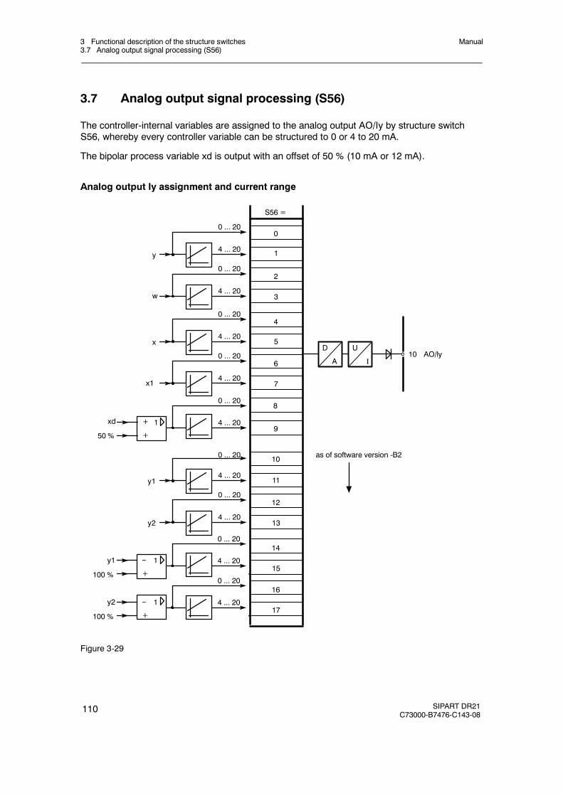
3 Functional description of the structure switches3.7 Analog output signal processing (S56)
Manual
110 SIPART DR21C73000-B7476-C143-08
3.7 Analog output signal processing (S56)
The controller-internal variables are assigned to the analog output AO/Iy by structure switchS56, whereby every controller variable can be structured to 0 or 4 to 20 mA.
The bipolar process variable xd is output with an offset of 50 % (10 mA or 12 mA).
Analog output Iy assignment and current range
0
S56 =
1
8
9
0 ... 20
0 ... 20
4 ... 20
4 ... 20
U
I
D
A10 AO/ly
+xd
50 %
1
+
0 ... 20
4 ... 20--y1
100 %
1
+
2
3
0 ... 20
4 ... 20
4
5
0 ... 20
4 ... 20
6
7
0 ... 20
4 ... 20
10
11
0 ... 20
4 ... 20
12
13
0 ... 20
4 ... 20y2
y1
y
w
x
x1
14
15
0 ... 20
4 ... 20--y2
100 %
1
+
16
17
as of software version -B2
Figure 3-29
3 Functional description of the structure switches3.8 Digital output signal processing (S57 to S75)
Manual
SIPART DR21C73000-B7476-C143-08
111
3.8 Digital output signal processing (S57 to S75)
The message signals RB, RC ... MUF, +Δw and -Δw are assigned to the digital outputs DO1 toDO8 by the structure switches S58 to S68 and can be negated optionally with the structureswitches S69 to S75 (except +Δw and -Δw) (see figure 3-30, page 112).
The digital outputs DO1, DO2 and DO7, DO8 of the standard controller can be extended withthe options modules 4DO 24 V +2DI (6DR2801-8E) or 2DO-relay 35 V (6DR2801-8A) in slot 3to a maximum 6 or 8 digital outputs respectively. When using 4DO 24 V +2DI in slot 3 by DO3to DO6, when using 2DO-relay 35 V in slot 3 by DO3 and DO4.
When using options modules in slot 3, structure switch S22 must be set according to the as-signment, otherwise there will be error messages (see chapter 5.5, page 179 ).
The control signals± Δ y (positioning increments of the S-controllers) are not negatable butthey can be assigned to one of the binary outputs DO1, DO2, DO7 or DO8. The setting of S57has priority over assignments with S58 to S68. The assigned digital outputs for±Δy are notstored in “ST5” and “BABE” (refresh-time approx. 20 ms). Decription of ST5 and BABE: seeoperating instructions “Serial SIPART 6DR190x Bus Interface”.
On assigning different control signals to the same digital output an OR-function of the controlsignals is produced (exception at±Δy).
Unassigned digital outputs (switch position 0) are low and can be set by SES at S85 = 2. Alldigital outputs have wired-or-diodes.
D Functional explanation of the digital message signals.
RB No computer standby of the controllerThis signal indicates that the controller is in internal operation, i.e. not in computerstandby.
RC Computer operationThis signal indicates the negated computer operation RC = Int∧CB and controls thesetpoint switching or DDC-operation.
H Manual modeThe controller is in manual mode, triggered either by manual/automatic-switching on thefront of the controller (Hi) or by the digital input signal He if the control signals Si,±yBLand N (with tracking over manual operation priority) are Low.
Nw Tracking operationThe controller is in tracking mode when the control signals Si,±yBL and H (in manualover tracking operation priority) are Low and the conmtrol signal N is High.
A1/A2 Alarm 1 and 2 indicate response of the limit value alarms A1 and A2.
A3/A4 Alarm 3 and 4 indicates response of the limit value alarms A3 and A4.
MUF Transmitter faultThe instruments’s analog input signals can be monitored for exceeding of the measuringrange. This signal gives a group alarm if an error is detected.
Δy positioning increments for the Δy-adjustment in S-controllers
Δw positioning increments for the Δw-adjustment, only for control unit/process display(S1 = 4)
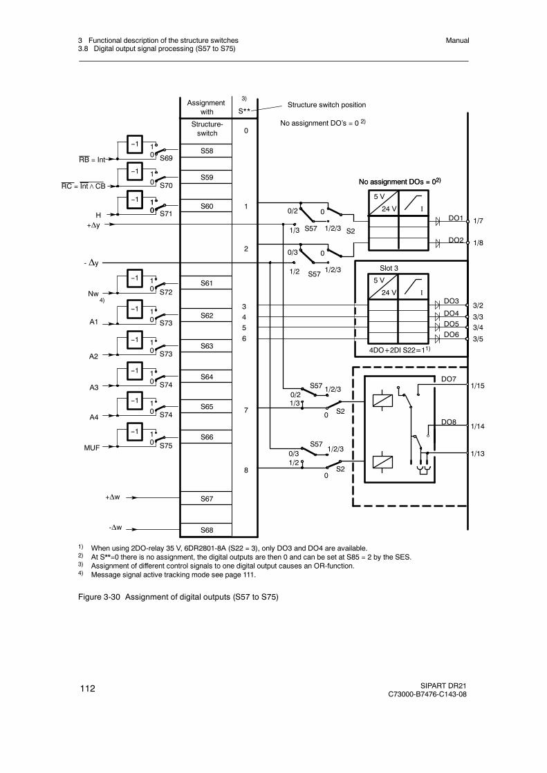
3 Functional description of the structure switches3.8 Digital output signal processing (S57 to S75)
Manual
112 SIPART DR21C73000-B7476-C143-08
No assignment DO’s = 0 2)
3)
S**Assignment
with
S58
S59
S60
S61
S62
S63
S64
S65
S66
S67
- Δy
Nw
A1
A2
A3
A4
MUF
Structure-switch
S68
+Δw
-Δw
Structure switch position
DO7
DO8
4)
0/2
1/3
0
1/2/3S57 S2
0/3
1/2
0
1/2/3S57
0/21/3
S57 1/2/3
0 S2
0/31/2
S571/2/3
0S2
S69
10
--1
S70
10
--1
S71
10
--1
RB = Int
RC = Int∧CB
H+Δy
10
--1
DO1
DO2
1/7
1/8
5 V
24 V I
No assignment DOs = 02)No assignment DOs = 02)
S72
10
--1
S73
10
--1
S73
10
--1
S74
10
--1
S74
10
--1
S75
10
--1
1
2
3/33/43/5
3/2
5 V
24 V I
Slot 3
DO3
DO4DO5DO6
4DO+2DI S22=11)
3456
1/15
1/14
1/13
7
8
0
1) When using 2DO-relay 35 V, 6DR2801-8A (S22 = 3), only DO3 and DO4 are available.2) At S**=0 there is no assignment, the digital outputs are then 0 and can be set at S85 = 2 by the SES.3) Assignment of different control signals to one digital output causes an OR-function.4) Message signal active tracking mode see page 111.
Figure 3-30 Assignment of digital outputs (S57 to S75)
3 Functional description of the structure switches3.9 Adaptation (S48)
Manual
SIPART DR21C73000-B7476-C143-08
113
3.9 Adaptation (S48)
The adaptation procedure represents a reliable and easy to operate commissioning tool. Theadaptation procedure is far superior to manual optimization especially in slow controlled sys-tems and in PID controller types. It is activated by the operator and can be aborted at any timein the event of danger. The parameters determined by the adaptation can be changed and ac-cepted specifically by the user.
In the parameterization mode AdAP which is only accessible at S48¸ 0, the following preset-tings are made for the adaptation procedure:
tU Monitoring timePv Direction of step commanddY Amplitude of step command
With the structure switch S48 the choice of the control behavior (with or without overshoot) ismade.
The adaptation principle is divided into system identification and controller design.
D System identification
The controller is driven to the desired operating point manually. By pressing the Enter keythe set manual manipulated variable is changed by a step adjustable in the direction (dPv)and amplitude (dY). The y-step is output at the end of 10 % of the set monitoring time (tU) ifthere was a fixed state of the controlled variable during this time. Otherwise there is an errormessage with abortion of the identification (see table 5-3, page 162 ).
The step response of the controlled system is then accepted with a max. 84 value pairs(time and amplitude). The respective main controlled variable of the different control types isfiltered adaptively -- (see figures 3-6, page 61 to figure 3-7, page 62) and provided for sav-ing. The storage procedure operates with cyclic data reduction and subsequent refilling sothat slow controlled systems can be entered.
After the start ID has been run through (the controlled variable x must have left the start IDband within 50% of the set monitoring time tU), 95% of the full range must have been re-ached at the latest at 2/3 of tU. The set monitoring time (tU) must be≥ 2 * T95 of the con-trolled system with safety reserve. The remaining time is required for the full scale identifica-tion. The end value identification can also take place immediately after the startidentification, but 1/3 of the performed measurements are always required for the end valueidentification. Recording of the measured value pairs is ended on identifying the full scale.
A comparison with the recorded transient function is now made based on the storedPtn-models with n = 1 to 8 and equal time constants T by variation of n and T. Thedetermined line gain ks is transfered to the line models. The comparison is made over theminimum error area F (n, T)
Additionally a special entry of real dead times is made which then shifts the identified controlline to higher orders.
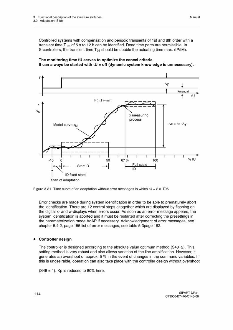
3 Functional description of the structure switches3.9 Adaptation (S48)
Manual
114 SIPART DR21C73000-B7476-C143-08
Controlled systems with compensation and periodic transients of 1st and 8th order with atransient time T 95 of 5 s to 12 h can be identified. Dead time parts are permissible. InS-controllers, the transient time T95 should be double the actuating time max. (tP/tM).
The monitoring time tU serves to optimize the cancel criteria.It can always be started with tU = off (dynamic system knowledge is unnecessary).
x
x measuringprocess
xM
Model curve xM
y
100500-10
F(n,T)=mintU
ymanual
Δy
Δx = ks⋅Δy
% tU
Full scaleID
67 %
Start ID
ID fixed state
Start of adaptation
Figure 3-31 Time curve of an adaptation without error messages in which tU = 2× T95
Error checks are made during system identification in order to be able to prematurely abortthe identification. There are 12 control steps altogether which are displayed by flashing onthe digital x- and w-displays when errors occur. As soon as an error message appears, thesystem identification is aborted and it must be restarted after correcting the presettings inthe parameterization mode AdAP if necessary. Acknowledgement of error messages, seechapter 5.4.2, page 155 list of error messages, see table 5-3page 162.
D Controller design
The controller is designed according to the absolute value optimum method (S48=2). Thissetting method is very robust and also allows variation of the line amplification. However, itgenerates an overshoot of approx. 5 % in the event of changes in the command variables. Ifthis is undesirable, operation can also take place with the controller design without overshoot
(S48 = 1). Kp is reduced to 80% here.
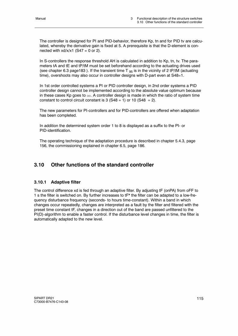
3 Functional description of the structure switches3.10 Other functions of the standard controller
Manual
SIPART DR21C73000-B7476-C143-08
115
The controller is designed for PI and PID-behavior, therefore Kp, tn and for PID tv are calcu-lated, whereby the derivative gain is fixed at 5. A prerequisite is that the D-element is con-nected with xd/x/x1 (S47 = 0 or 2).
In S-controllers the response threshold AH is calculated in addition to Kp, tn, tv. The para-meters tA and tE and tP/tM must be set beforehand according to the actuating drives used(see chapter 6.3 page183 ). If the transient time T 95 is in the vicinity of 2 tP/tM (actuatingtime), overshoots may also occur in controller designs with D-part even at S48=1.
In 1st order controlled systems a PI or PID controller design, in 2nd order systems a PIDcontroller design cannot be implemented according to the absolute value optimum becausein these cases Kp goes to1. A controller design is made in which the ratio of system timeconstant to control circuit constant is 3 (S48 = 1) or 10 (S48 = 2).
The new parameters for PI-controllers and for PID-controllers are offered when adaptationhas been completed.
In addition the determined system order 1 to 8 is displayed as a suffix to the PI- orPID-identification.
The operating technique of the adaptation procedure is described in chapter 5.4.3, page156, the commissioning explained in chapter 6.5, page 186.
3.10 Other functions of the standard controller
3.10.1 Adaptive filter
The control difference xd is fed through an adaptive filter. By adjusting tF (onPA) from oFF to1 s the filter is switched on. By further increases to tF* the filter can be adapted to a low-fre-quency disturbance frequency (seconds- to hours time-constant). Within a band in whichchanges occur repeatedly, changes are interpreted as a fault by the filter and filtered with thepreset time constant tF, changes in a direction out of the band are passed unfiltered to thePI(D)-algorithm to enable a faster control. If the disturbance level changes in time, the filter isautomatically adapted to the new level.
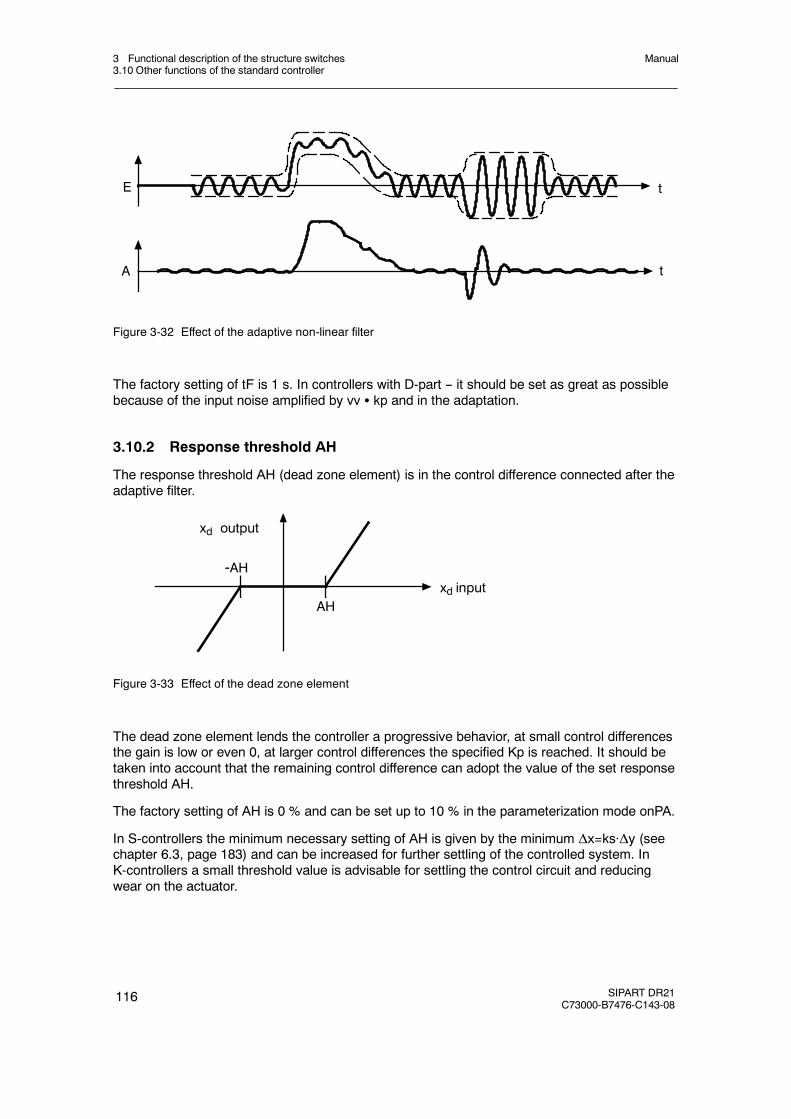
3 Functional description of the structure switches3.10 Other functions of the standard controller
Manual
116 SIPART DR21C73000-B7476-C143-08
E
A t
t
Figure 3-32 Effect of the adaptive non-linear filter
The factory setting of tF is 1 s. In controllers with D-part -- it should be set as great as possiblebecause of the input noise amplified by vv S kp and in the adaptation.
3.10.2 Response threshold AH
The response threshold AH (dead zone element) is in the control difference connected after theadaptive filter.
-AH
AH
xd output
xd input
Figure 3-33 Effect of the dead zone element
The dead zone element lends the controller a progressive behavior, at small control differencesthe gain is low or even 0, at larger control differences the specified Kp is reached. It should betaken into account that the remaining control difference can adopt the value of the set responsethreshold AH.
The factory setting of AH is 0 % and can be set up to 10 % in the parameterization mode onPA.
In S-controllers the minimum necessary setting of AH is given by the minimum Δx=ks·Δy (seechapter 6.3, page 183) and can be increased for further settling of the controlled system. InK-controllers a small threshold value is advisable for settling the control circuit and reducingwear on the actuator.
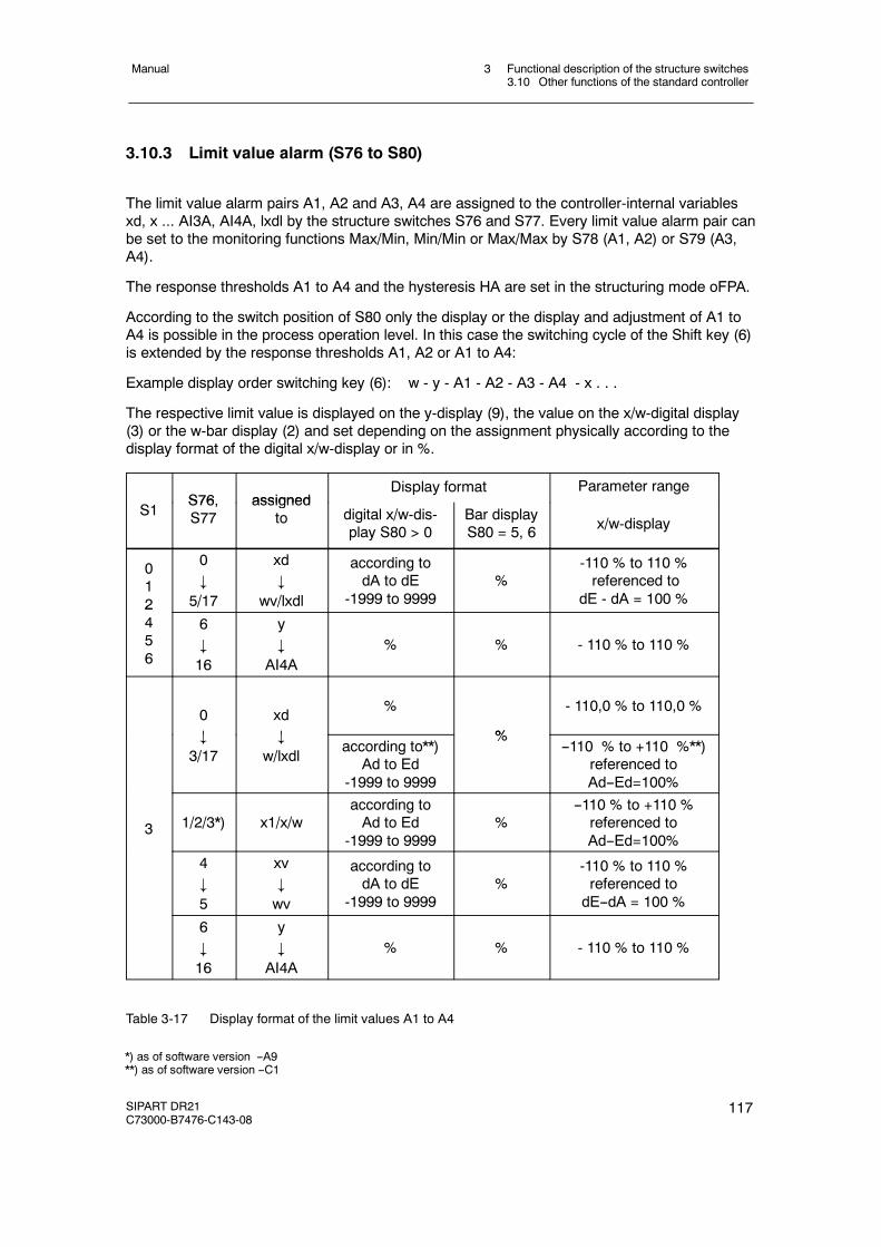
3 Functional description of the structure switches3.10 Other functions of the standard controller
Manual
SIPART DR21C73000-B7476-C143-08
117
3.10.3 Limit value alarm (S76 to S80)
The limit value alarm pairs A1, A2 and A3, A4 are assigned to the controller-internal variablesxd, x ... AI3A, AI4A, lxdl by the structure switches S76 and S77. Every limit value alarm pair canbe set to the monitoring functions Max/Min, Min/Min or Max/Max by S78 (A1, A2) or S79 (A3,A4).
The response thresholds A1 to A4 and the hysteresis HA are set in the structuring mode oFPA.
According to the switch position of S80 only the display or the display and adjustment of A1 toA4 is possible in the process operation level. In this case the switching cycle of the Shift key (6)is extended by the response thresholds A1, A2 or A1 to A4:
Example display order switching key (6): w - y - A1 - A2 - A3 - A4 - x . . .
The respective limit value is displayed on the y-display (9), the value on the x/w-digital display(3) or the w-bar display (2) and set depending on the assignment physically according to thedisplay format of the digital x/w-display or in %.
S76 assignedDisplay format Parameter range
S1S76,S77
assignedto digital x/w-dis-
play S80 > 0Bar displayS80 = 5, 6 x/w-display
012
0#
5/17
xd#
wv/lxdl
according todA to dE
-1999 to 9999%
-110 % to 110 %referenced to
dE - dA = 100 %2456
6#
16
y#
AI4A% % - 110 % to 110 %
0#
xd#
%
%
- 110,0 % to 110,0 %
#
3/17#
w/lxdlaccording to**)
Ad to Ed-1999 to 9999
%--110 % to +110 %**)
referenced toAd--Ed=100%
3 1/2/3*) x1/x/waccording toAd to Ed
-1999 to 9999%
--110 % to +110 %referenced toAd--Ed=100%
4#
5
xv#
wv
according todA to dE
-1999 to 9999%
-110 % to 110 %referenced todE--dA = 100 %
6#
16
y#
AI4A% % - 110 % to 110 %
Table 3-17 Display format of the limit values A1 to A4
*) as of software version --A9**) as of software version --C1

3 Functional description of the structure switches3.10 Other functions of the standard controller
Manual
118 SIPART DR21C73000-B7476-C143-08
A2 cannot be set greater than A1 and A4 not greater than A3.
The hysteresis HA is set in % in the range from 0.1 to 10 % and applies for all 4 limit values.
The function of the limit values (Min oder Max) always relates to the display, i.e. in the case of afalling characteristic (dE< dA) the direction of effect is reversed. The set Min-function forexample becomes a Max-function related to the field signal.
S77
S76
Assignmentwith
S**
xd
x1
x
w
xv
wv
y
y1
y2
AI1
AI2
AI3
AI4
AI1A
AI2A
AI3A
AI4A
lxdl
0
1
2
3
4
5
6
7
8
9
10
11
12
13
14
15
16
17
A1 +--
Min.
+--
Max
S78
0
HA
A1
2
0
1
+--+-- 0
HA
A2
A2
A1≥A2
Min.
Max
S78
2
0
1
A3 +--
Min.
+--
Max
S79
0
HA
A3
2
0
1
+--+-- 0
HA
A4
A4
A3≥A4
Min.
Max
S79
2
0
1
Figure 3-34 Assignment and function of the limit value alarms (S76 to S79)
3.10.4 Linearizer (S21, oFPA)
The linearizer is freely assignable to an input AI1 to AI4 or the main controlled variable x1. If themain controlled variable is linearized, the range dA to dE is decisive, otherwise there is a per-centage reference to the measuring range. The curve is rounded at the support points.
Example:Thermocouple 300 to 1000 C with transmitter without linearizer
Set start of scale and full scale dA and dE and the decimal point dP in the structuring modeoFPA for the display. Divide measuring range UA to UE including± 10 % overflow in 10 % sec-tions and determine partial voltages. L -1 to L11 are equidistant support points with 10 %-steps.
Un = n + UA with n = --1 to 11UE-UA10
UA = 4.31 mVUE = 48.33 mV

3 Functional description of the structure switches3.10 Other functions of the standard controller
Manual
SIPART DR21C73000-B7476-C143-08
119
Determine the respective physical value from the appropriate function tables for every Un orgraphically from the corresponding curve (interpolate if necessary) and enter the value for therespective vertex value (L-1 to L11 ) in physical variables in the structuring mode oFPA.
UE
8 39.526 ! L8 900
7 35.124 ! L7 846
6 30.722 ! L6 790
5 26.32 ! L5 729
4 21.918 ! L4 664
3 17.516 ! L3 593
2 13.114 ! L2 514
1 8.712 ! L1 420
0 4.31 ! L0 300
-1 -0.092 ! L-1 0tA tE
UE=48.33 mV
60
50
40
30
20
10
0
0 100 200 300 400 500 600 700 800 900 1000 1200
110
100
90
80
70
60
50
40
30
20
10
0
-10
UA=4.31 mV
UE
dA dE
t [˚C]
%n Un [mV] vertex- t [˚C]
value
11 52.732 ! L11 1048
10 48,33 ! L10 1000
9 43.928 ! L9 951
[mV]
Figure 3-35 Example of linearization of a thermocouple type B Pt30Rh/Pt6, measuring range dA to dEfrom 300 to 1000 C
3 Functional description of the structure switches3.10 Other functions of the standard controller
Manual
120 SIPART DR21C73000-B7476-C143-08
3.10.5 Restart conditions (S82, S83)
The restart conditions after mains recovery are determined with S82. With S82 = 0 the con-troller starts after mains recovery and after a watch-dog-reset with the operating mode and withthe y which was active before the power failure. This variation must be used when temporarymains failures are to be expected in slow control circuits.
With S82 = 1 starting after mains recovery takes place in manual- and in internal operation withys in the K-controller (S2 = 0) and two-position controller (S2 = 1) or with the last y in the three-position controller (S2 = 2, 3). If only external operating mode or only automatic operation wasselected by S42 = 1 or S51 = 1 respectively, the restart takes place in these operating modes.
With S83 the optical signaling of mains voltage recovery and reset is determined by flashing ofthe digital x-display. The flashing is acknowledged by pressing the Shift key (6) or by an alarmrequest via SES.
3.10.6 Serial interface and PROFIBUS-DP (S84 to S91)
The structure switch determines whether operation is with SES (S84 = 1/2/3*)) or without SES(S84 = 0) (see also “Control system coupling via the serial interface”, page 109).
With S85 the depth of the SES-interventions is preset. Generally all available set data are read.In position 0 no transmission and reception of data to the controller is possible. In position 1only parameters and structures can be transmitted. In positions 2 to 5 the process variableswES (external setpoint via the SES), wiES (internal setpoint via the SES), yES (external manipu-lated variable via the SES), yHES (manual manipulated variable via the SES) and all control sig-nals can be sent additionally via the SES. At the same time, S85 switches over the sources forthe external setpoint wES or wEA and for the tracking manipulated variable y ES or yN. Thismakes it possible to preset the process variables and the control signals only via the SES or theprocess variables analogly and only the control signals via the SES.
With S84 = 1/2 writing of status signal SiES to tSHES can be locked via /RC or CB.
The structure switches S86 to S91 determine the transmission procedure through the serialinterface. See the user guide “Serial SIPART DR21 Bus Interface” for explanations; Internetaddress: www.fielddevices.com [Edition 05.2000].
Settings for PROFIBUS-DP see table 5-5, page 172 (structure switch list).
*) as of software version C1
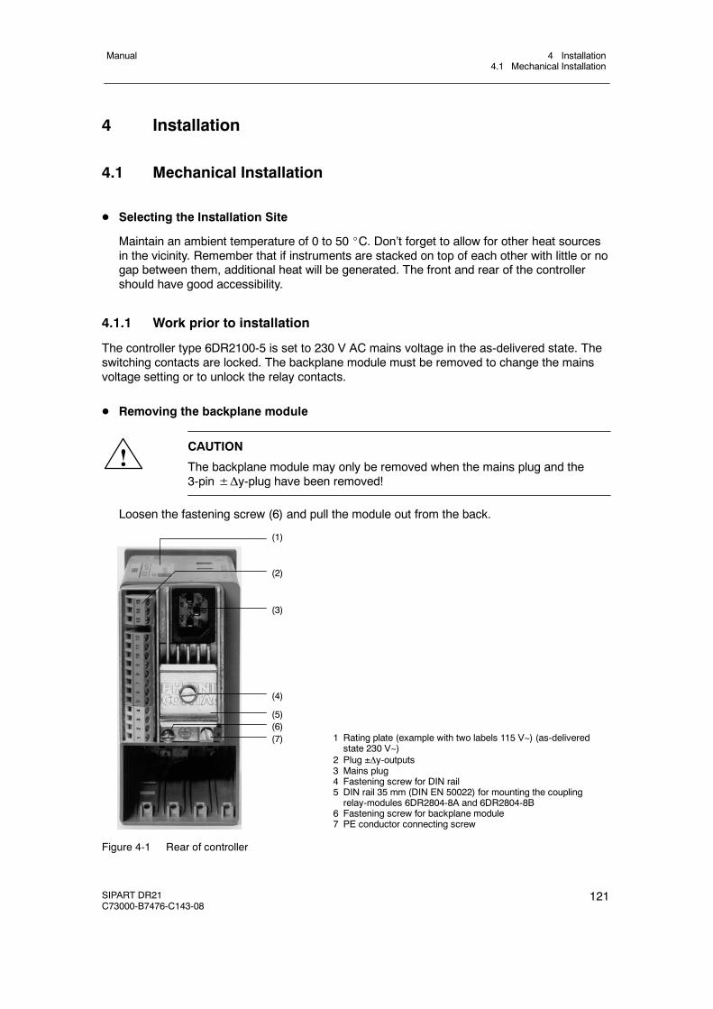
4 Installation4.1 Mechanical Installation
Manual
SIPART DR21C73000-B7476-C143-08
121
4 Installation
4.1 Mechanical Installation
D Selecting the Installation Site
Maintain an ambient temperature of 0 to 50 _C. Don’t forget to allow for other heat sourcesin the vicinity. Remember that if instruments are stacked on top of each other with little or nogap between them, additional heat will be generated. The front and rear of the controllershould have good accessibility.
4.1.1 Work prior to installation
The controller type 6DR2100-5 is set to 230 V AC mains voltage in the as-delivered state. Theswitching contacts are locked. The backplane module must be removed to change the mainsvoltage setting or to unlock the relay contacts.
D Removing the backplane module
!CAUTION
The backplane module may only be removed when the mains plug and the3-pin±Δy-plug have been removed!
Loosen the fastening screw (6) and pull the module out from the back.
(1)
(2)
(7)
(4)
(5)(6)
(3)
1 Rating plate (example with two labels 115 V~) (as-deliveredstate 230 V~)
2 Plug y-outputs3 Mains plug4 Fastening screw for DIN rail5 DIN rail 35 mm (DIN EN 50022) for mounting the couplingrelay-modules 6DR2804-8A and 6DR2804-8B
6 Fastening screw for backplane module7 PE conductor connecting screw
Figure 4-1 Rear of controller

4 Installation4.1 Mechanical Installation
Manual
122 SIPART DR21C73000-B7476-C143-08
D Switching mains 230 V to 115 V
Fastening screw
Plug-in jumpers(in the as-delivered state 230 V)
Figure 4-2 Setting the mains voltage
Re-plug jumpers as shown in the diagram in figure 4-2.Stick the two labels provided (115 V power supply) to the rating plate in the field 230 V ACand on the housing to the right of the mains plug vertically to the rear of the housing (seefigure4-1). Re-install the backplane accordingly.
D Unlock the relay contacts
Re-plug the plug-in jumper (figure 4-4, page 123) to unlock.
Labeling according to DIN 45100Labeling on theterminal block
15 47
14 49
13 48
3-pin+/--y-plug
Relay contacts
DO7 (+y)
DO8 (--y)
locked (as-delivered state)
unlocked
Figure 4-3 Circuit
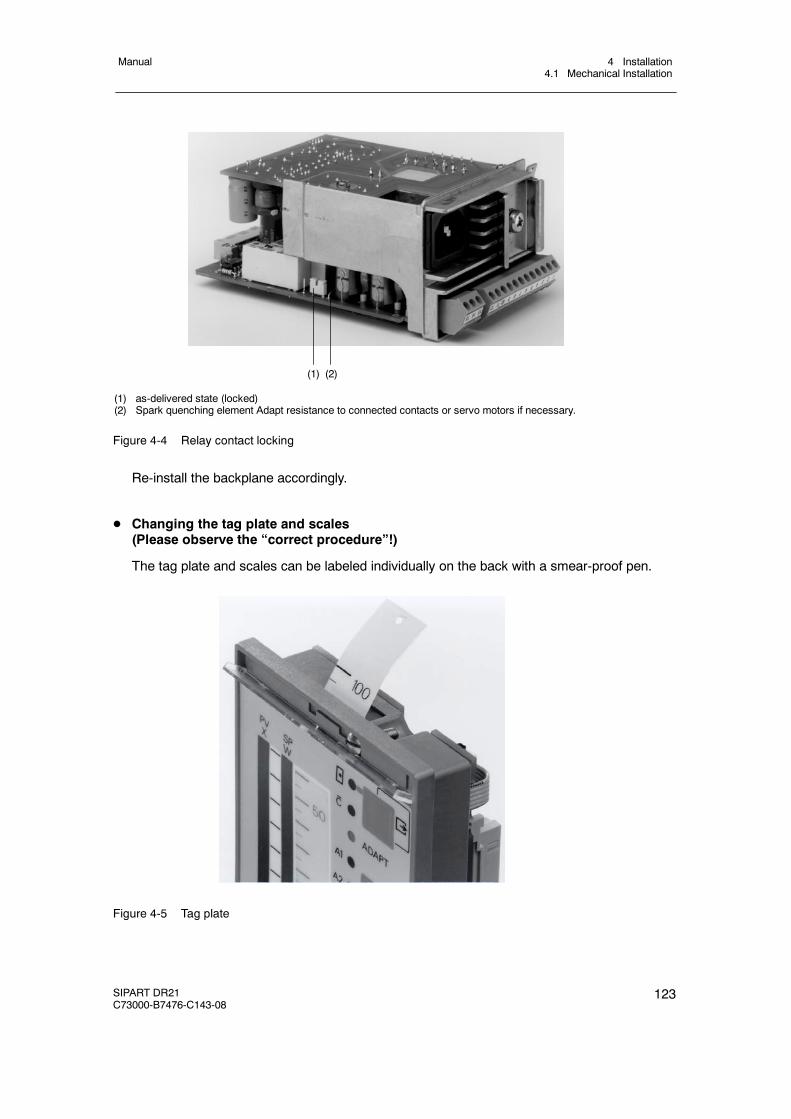
4 Installation4.1 Mechanical Installation
Manual
SIPART DR21C73000-B7476-C143-08
123
(1) as-delivered state (locked)(2) Spark quenching element Adapt resistance to connected contacts or servo motors if necessary.
(1) (2)
Figure 4-4 Relay contact locking
Re-install the backplane accordingly.
D Changing the tag plate and scales(Please observe the “correct procedure”!)
The tag plate and scales can be labeled individually on the back with a smear-proof pen.
Figure 4-5 Tag plate
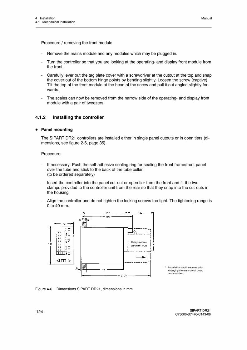
4 Installation4.1 Mechanical Installation
Manual
124 SIPART DR21C73000-B7476-C143-08
Procedure / removing the front module
- Remove the mains module and any modules which may be plugged in.
- Turn the controller so that you are looking at the operating- and display front module fromthe front.
- Carefully lever out the tag plate cover with a screwdriver at the cutout at the top and snapthe cover out of the bottom hinge points by bending slightly. Loosen the screw (captive)Tilt the top of the front module at the head of the screw and pull it out angled slightly for-wards.
- The scales can now be removed from the narrow side of the operating- and display frontmodule with a pair of tweezers.
4.1.2 Installing the controller
D Panel mounting
The SIPART DR21 controllers are installed either in single panel cutouts or in open tiers (di-mensions, see figure 2-6, page 35).
Procedure:
- If necessary: Push the self-adhesive sealing ring for sealing the front frame/front panelover the tube and stick to the back of the tube collar.(to be ordered separately)
- Insert the controller into the panel cut-out or open tier from the front and fit the twoclamps provided to the controller unit from the rear so that they snap into the cut-outs inthe housing.
- Align the controller and do not tighten the locking screws too tight. The tightening range is0 to 40 mm.
* Installation depth necessary forchanging the main circuit boardand modules
Relay module
Figure 4-6 Dimensions SIPART DR21, dimensions in mm
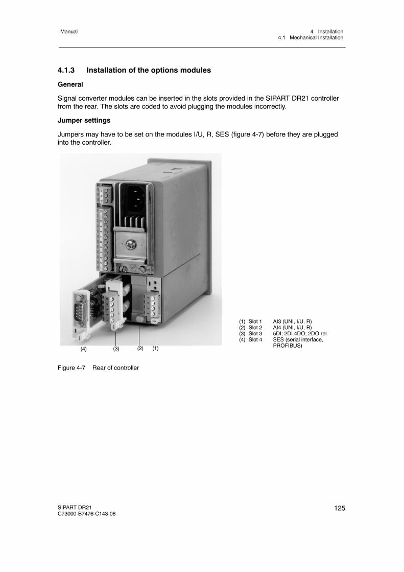
4 Installation4.1 Mechanical Installation
Manual
SIPART DR21C73000-B7476-C143-08
125
4.1.3 Installation of the options modules
General
Signal converter modules can be inserted in the slots provided in the SIPART DR21 controllerfrom the rear. The slots are coded to avoid plugging the modules incorrectly.
Jumper settings
Jumpers may have to be set on the modules I/U, R, SES (figure 4-7) before they are pluggedinto the controller.
(1) Slot 1 AI3 (UNI, I/U, R)(2) Slot 2 AI4 (UNI, I/U, R)(3) Slot 3 5DI; 2DI 4DO; 2DO rel.(4) Slot 4 SES (serial interface,
PROFIBUS)(1)(2)(3)(4)
Figure 4-7 Rear of controller
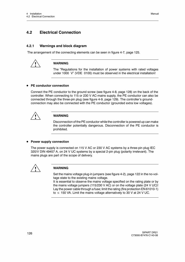
4 Installation4.2 Electrical Connection
Manual
126 SIPART DR21C73000-B7476-C143-08
4.2 Electrical Connection
4.2.1 Warnings and block diagram
The arrangement of the connecting elements can be seen in figure 4-7, page 125.
! WARNING
The ”Regulations for the installation of power systems with rated voltagesunder 1000 V” (VDE 0100) must be observed in the electrical installation!
D PE conductor connection
Connect the PE conductor to the ground screw (see figure 4-8, page 128) on the back of thecontroller. When connecting to 115 or 230 V AC-mains supply, the PE conductor can also beconnected through the three-pin plug (see figure 4-9, page 129). The controller’s ground-connection may also be connected with the PE conductor (grounded extra low voltages).
! WARNING
Disconnection of thePEconductor while the controller is poweredup canmakethe controller potentially dangerous. Disconnection of the PE conductor isprohibited.
D Power supply connection
The power supply is connected on 115 V AC or 230 V AC systems by a three-pin plug IEC320/V DIN 49457 A, on 24 V UC systems by a special 2-pin plug (polarity irrelevant). Themains plugs are part of the scope of delivery.
! WARNING
Set the mains voltage plug-in jumpers (see figure 4-2), page 122 in the no-vol-tage state to the existing mains voltage.It is essential to observe the mains voltage specified on the rating plate or bythe mains voltage jumpers (115/230 V AC) or on the voltage plate (24 V UC)!Lay the power cable through a fuse; limit the rating (fire protection EN61010-1)to≤ 150 VA. Limit the mains voltage alternatively to 30 V at 24 V UC.
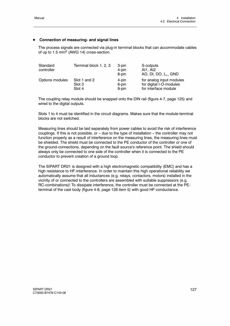
4 Installation4.2 Electrical Connection
Manual
SIPART DR21C73000-B7476-C143-08
127
D Connection of measuring- and signal lines
The process signals are connected via plug-in terminal blocks that can accommodate cablesof up to 1.5 mm2 (AWG 14) cross-section.
Standardcontroller
Terminal block 1, 2, 3 3-pin4-pin8-pin
S-outputsAI1, AI2AO, DI, DO, L+, GND
Options modules Slot 1 and 2Slot 3Slot 4
4-pin6-pin9-pin
for analog input modulesfor digital I-O-modulesfor interface module
The coupling relay module should be snapped onto the DIN rail (figure 4-7, page 125) andwired to the digital outputs.
Slots 1 to 4 must be identified in the circuit diagrams. Makes sure that the module-terminalblocks are not switched.
Measuring lines should be laid separately from power cables to avoid the risk of interferencecouplings. If this is not possible, or -- due to the type of installation -- the controller may notfunction properly as a result of interference on the measuring lines, the measuring lines mustbe shielded. The shield must be connected to the PE conductor of the controller or one ofthe ground-connections, depending on the fault source’s reference point. The shield shouldalways only be connected to one side of the controller when it is connected to the PEconductor to prevent creation of a ground loop.
The SIPART DR21 is designed with a high electromagnetic compatibility (EMC) and has ahigh resistance to HF-interference. In order to maintain this high operational reliability weautomatically assume that all inductances (e.g. relays, contactors, motors) installed in thevicinity of or connected to the controllers are assembled with suitable suppressors (e.g.RC-combinations)! To dissipate interference, the controller must be connected at the PE-terminal of the cast body (figure 4-8, page 128 item 5) with good HF-conductance.
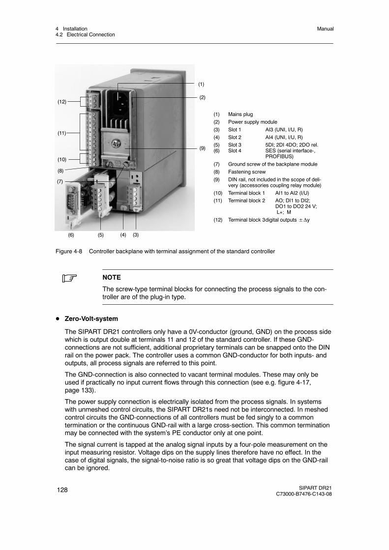
4 Installation4.2 Electrical Connection
Manual
128 SIPART DR21C73000-B7476-C143-08
(1) Mains plug(2) Power supply module(3) Slot 1 AI3 (UNI, I/U, R)(4) Slot 2 AI4 (UNI, I/U, R)(5) Slot 3 5DI; 2DI 4DO; 2DO rel.(6) Slot 4 SES (serial interface-,
PROFIBUS)(7) Ground screw of the backplane module(8) Fastening screw(9) DIN rail, not included in the scope of deli-
very (accessories coupling relay module)(10) Terminal block 1 AI1 to AI2 (I/U)(11) Terminal block 2 AO; DI1 to DI2;
DO1 to DO2 24 V;L+; M
(12) Terminal block 3digital outputs±Δy
(6) (5) (4) (3)
(7)
(8)
(10)
(9)
(11)
(12)(2)
(1)
Figure 4-8 Controller backplane with terminal assignment of the standard controller
. NOTE
The screw-type terminal blocks for connecting the process signals to the con-troller are of the plug-in type.
D Zero-Volt-system
The SIPART DR21 controllers only have a 0V-conductor (ground, GND) on the process sidewhich is output double at terminals 11 and 12 of the standard controller. If these GND-connections are not sufficient, additional proprietary terminals can be snapped onto the DINrail on the power pack. The controller uses a common GND-conductor for both inputs- andoutputs, all process signals are referred to this point.
The GND-connection is also connected to vacant terminal modules. These may only beused if practically no input current flows through this connection (see e.g. figure 4-17,page 133).
The power supply connection is electrically isolated from the process signals. In systemswith unmeshed control circuits, the SIPART DR21s need not be interconnected. In meshedcontrol circuits the GND-connections of all controllers must be fed singly to a commontermination or the continuous GND-rail with a large cross-section. This common terminationmay be connected with the system’s PE conductor only at one point.
The signal current is tapped at the analog signal inputs by a four-pole measurement on theinput measuring resistor. Voltage dips on the supply lines therefore have no effect. In thecase of digital signals, the signal-to-noise ratio is so great that voltage dips on the GND-railcan be ignored.
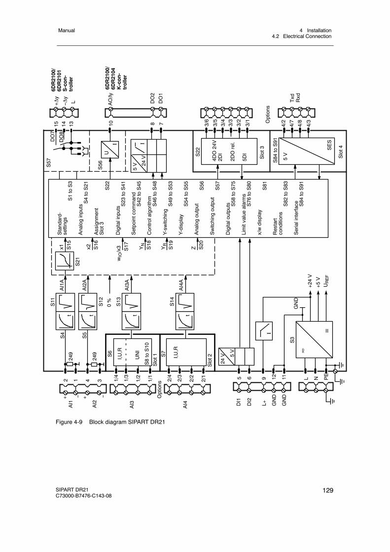
4 Installation4.2 Electrical Connection
Manual
SIPART DR21C73000-B7476-C143-08
129
10
AI4A
S13
AI3A
S11
AI1A
S6
2 1 4 3
t
AI3
Slot1 S7
Slot2I,U
,R
I,U,R
AI4
Options
0%
YN
S18
DI1
DI2
24V 5V
L+ GND
GND
NL
GND
+24V
+5V
UREF
S14
t
S21
S57
DO7
DO8
24V
5V
I
U
I
S56
15 14 13 8 7
S22
Z S20
YR
S19
wIO/x3 S17x2 S16
x1 S15
4DO24V
2DI
2DOrel.
5DI
Slot3
S84
toS91
4/2
4/7
4/8
4/3
Slot4SES
5V
DO2
DO1
+Δy
--Δy
AO/ly
IOptions
Standard-
settings
S1toS3
AnaloginputsS4toS21
Assignm
ent
Slot3
S22
Digitalinputs S23
toS41
Setpointcom
mand
S42
toS45
Controlalgorithm
S46
toS48
Y-sw
itching
S49
toS53
Y-display
S54
toS55
Analogoutput
S56
Switching
output
S57
Digitaloutputs S58
toS75
Limitvaluealarms
S76
toS80
x/wdisplay
S81
Restart
conditions
S82
toS83
Serialinterface S84
toS91
Txd
Rxd
S3
=
1/4
1/3
1/2
1/1
2/4
2/3
2/2
2/1 5 6 12 119 PE
3/6
3/5
3/4
3/3
3/2
3/1
AI1
--+
AI2
UNI
S8toS10
t
S12
AI2A
S4
S5
249
249
--+
6DR2100/
6DR2101
S-con-
troller
L
6DR2100/
6DR2104
K-con-
troller
t t
Figure 4-9 Block diagram SIPART DR21

4 Installation4.2 Electrical Connection
Manual
130 SIPART DR21C73000-B7476-C143-08
4.2.2 Connection standard controller
D Power supply connection
!CAUTION
Pay attention to mains jumpering (see figure 4-2, page 122)!
- 6DR210x-5 (115/230 V AC)
=
+24 V+5 VUREF
0.63 A slow-blow at 115 V0.315 A slow-blow at 230 V
per controller
1)
L
N
Three-pin plug IEC 320 IV DIN 49457A
230 V115 V
PE
L N PE115 or 230 V AC
DR216DR210x-5
Fusing of the supply lineto VDE 0411 part 1EN61 010, part 1 max. 150 VA
Other loads on the samecontrol loop
Figure 4-10 Connection 115/230 V AC power supply
- 6DR210x-4 (24 V UC)
=
1.6A, slow-blow
per controller
1)
L
N
Special 2-pin plug, any polarity
UL = 24 V UC
+24 V+5 VUREF
Fusing of the supply lineto VDE 0411 part 1EN61 010, part 1 max. 150 VAor UL≤30 V
Other loads on the samecontrol loop
DR216DR210x-4
Figure 4-11 Connection 24 V UC power supply
1) The connection between the PE conductor screw (figure4-8, item 5, page128) to ground must be established addition-ally for high electromagnetic compatibility (EMC) in 115/230 V-controllers.This connection must also be low resistive for high frequencies (Cu-band or Hf-strand). Alternatively at least 2.5 mm2
flexible should be used.

4 Installation4.2 Electrical Connection
Manual
SIPART DR21C73000-B7476-C143-08
131
D Connection of measuring- and signal lines AI1 and AI2
11/12
3
2 4
1
9
AI2AI1
I
+
UH +UH4L2L
-
L+
AI+
AI-
L+
AI+
AI-
++
IAI+
GND
AI+
AI--
GND
--
GND GND
I
I
1)
1) The series circuiting of several inputs is not possible because AI1/2 is connected internally to GND.
Set 0/4 to 20 mA with S4 to S5
AI--
Figure 4-12 Wiring AI1 to AI2, current inputs
D DI1 to DI2
<4.5 V
>13 V or
9
5
6
11/12
DI1
DI2
L+
GND
Set function with S23 to S33/S92Set direction of effect with S34 to S40
Figure 4-13 Connection DI1 to DI2
D AO
≤ 900 Ω
0/4 ... 20 mA10
11/12GND
Function: 0/4 to 20 mASet with S56
AO
Figure 4-14 Connection AO
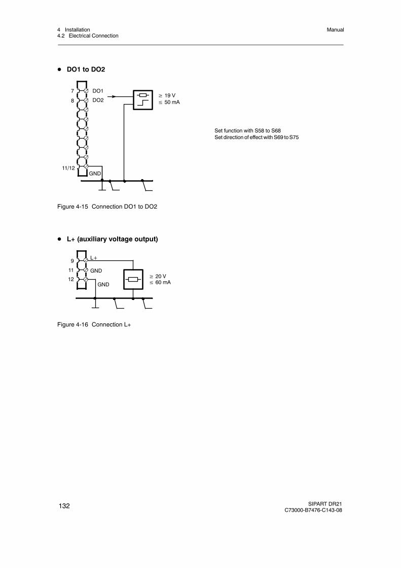
4 Installation4.2 Electrical Connection
Manual
132 SIPART DR21C73000-B7476-C143-08
D DO1 to DO2
DO1
DO2
7
8≥ 19 V≤ 50 mA
GND
Set function with S58 to S68Set direction of effect with S69 toS75
11/12
Figure 4-15 Connection DO1 to DO2
D L+ (auxiliary voltage output)
≥ 20 V≤ 60 mA
L+
GND
GND
9
11
12
Figure 4-16 Connection L+

4 Installation4.2 Electrical Connection
Manual
SIPART DR21C73000-B7476-C143-08
133
4.2.3 Connection of the options modules
4.2.3.1 Modules for analog measuring inputs
D 6DR2800-8J (U or I-input)
+
GNDGND
UH
I 4L+UH
U
+
0/2 ... 10 V 0/0.2 ... 1 V
x5=x6/10 V x4=x5/1 V(x8=x9) (x7=x8)
I
0/4 ... 20 mA
x4=x5/1 V(x7=x8)
U
factory setting 1 V, x4=x5 (and x7=x8)
Set AI3 in slot 1 with S6 measuring range 0 to 1 V, 10 V, 20 mA orAI4 in slot 2 with S7 0.2 V, 2 V, 4 mA to 1 V, 10 V, 20 mA
3114
3923
3122
1
12
3114
3923
3122
1
12
--
+
GND
I
1) possible load resistances of other controllers2) x7, x8, x9 omitted from the circuit board
C73451--A3000-L106
3114
3923
3122
1
12
--
L+9
1)0 to
500 Ω
1 V/10 V
49,9Ω
GND
+
--
x4 x5 x6
x7 x8 x9 2)1 V 10 V
6DR2800-8J
I 2L
Figure 4-17 Connection U/I-module 6DR2800-8J
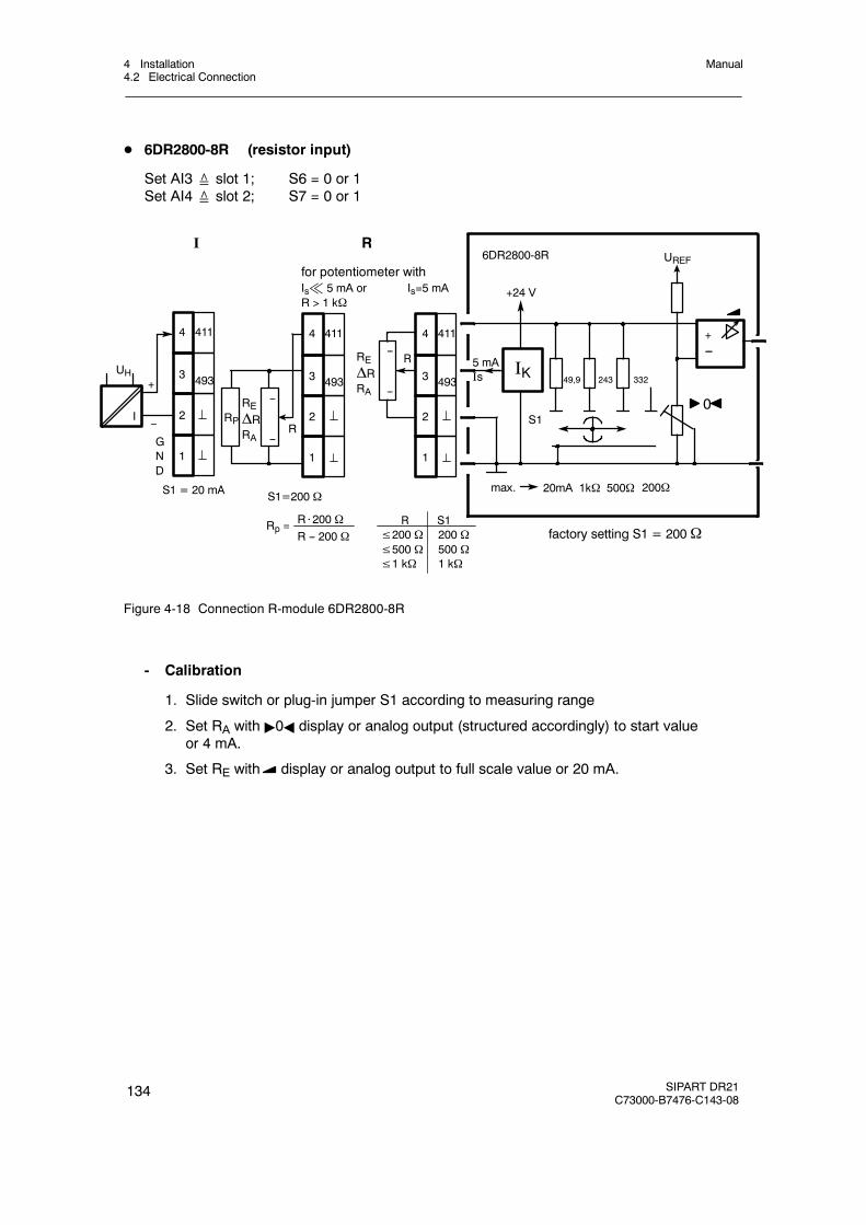
4 Installation4.2 Electrical Connection
Manual
134 SIPART DR21C73000-B7476-C143-08
D 6DR2800-8R (resistor input)
Set AI3≙ slot 1; S6 = 0 or 1Set AI4≙ slot 2; S7 = 0 or 1
R S1≤200 Ω 200 Ω≤500 Ω 500 Ω≤1 kΩ 1 kΩ
max.
UREF
20mA 1kΩ 500Ω
49,9 243 332
5 mAIs IK
R
0
+24 V
S1R
REΔRRA
+
GND
6DR2800-8Rfor potentiometer withIs% 5 mA or Is=5 mAR > 1 kΩ
I R
factory setting S1 = 200Ω
S1 = 20 mA
R⋅200 ΩR -- 200 Ω
Rp =
4114
4933
2
1
4114
4933
2
1
S1=200 Ω
I
REΔRRA
4114
4933
2
1
+--
UH
RP--
--
--
--
--
200Ω
Figure 4-18 Connection R-module 6DR2800-8R
- Calibration
1. Slide switch or plug-in jumper S1 according to measuring range
2. Set RA with "0A display or analog output (structured accordingly) to start valueor 4 mA.
3. Set RE with display or analog output to full scale value or 20 mA.
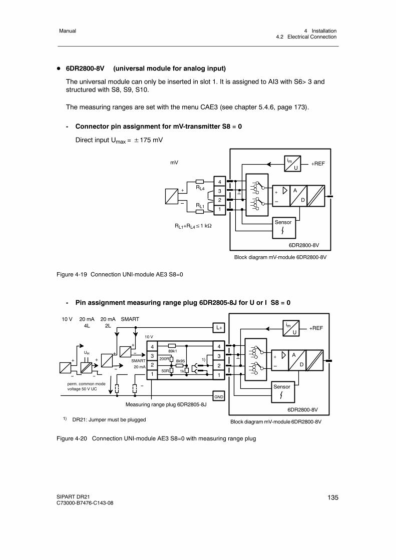
4 Installation4.2 Electrical Connection
Manual
SIPART DR21C73000-B7476-C143-08
135
D 6DR2800-8V (universal module for analog input)
The universal module can only be inserted in slot 1. It is assigned to AI3 with S6> 3 andstructured with S8, S9, S10.
The measuring ranges are set with the menu CAE3 (see chapter 5.4.6, page 173).
- Connector pin assignment for mV-transmitter S8 = 0
Direct input Umax =±175 mV
RL4
RL1
RL1+RL4≤1 kΩ
+
--
mV
Block diagram mV-module 6DR2800-8V
imU
+REF
+
--
A
D
Sensor
6DR2800-8V
4
3
2
1
Figure 4-19 Connection UNI-module AE3 S8=0
- Pin assignment measuring range plug 6DR2805-8J for U or I S8 = 0
4
3
2
1
89k1
200R 8k95
50R 1k
10 V
+
--SMART
20 mA
+
--perm. common modevoltage 50 V UC
UH
+
--
Measuring range plug 6DR2805-8J
Block diagrammV-module 6DR2800-8V
imU
+REF
+
--
A
D
Sensor
6DR2800-8V
4
3
2
1
+
--
10 V 20 mA4L
20 mA2L
SMART
--
L+
GND
1) DR21: Jumper must be plugged
1)
--
Figure 4-20 Connection UNI-module AE3 S8=0 with measuring range plug
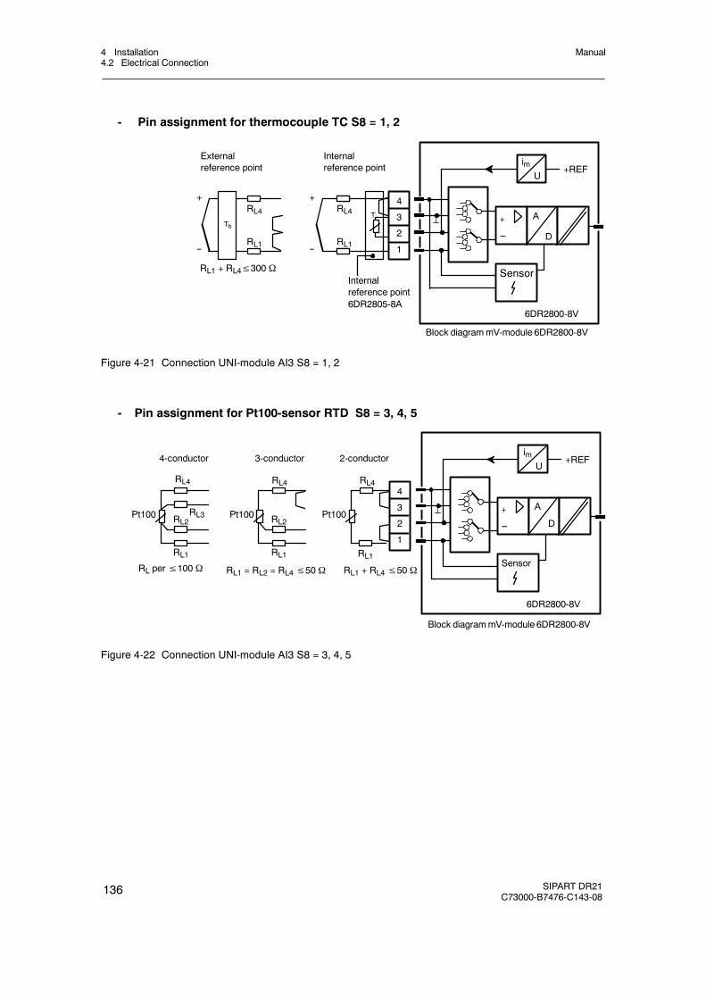
4 Installation4.2 Electrical Connection
Manual
136 SIPART DR21C73000-B7476-C143-08
- Pin assignment for thermocouple TC S8 = 1, 2
imU
+REF
+
--
A
D
Sensor
6DR2800-8V
4
3
2
1
RL4
RL1 + RL4≤300 Ω
T
RL1
Internalreference point6DR2805-8A
Internalreference point
+
--
RL4
RL1
+
--
Tb
Externalreference point
Block diagrammV-module 6DR2800-8V
Figure 4-21 Connection UNI-module AI3 S8 = 1, 2
- Pin assignment for Pt100-sensor RTD S8 = 3, 4, 5
RL per≤100 Ω
RL4
Pt100
4-conductor
RL1
2-conductor
RL4
Pt100
RL1
RL2
3-conductor
RL4
Pt100
RL1
RL2RL3
RL1 = RL2 = RL4≤50 Ω RL1 + RL4≤50 Ω
Block diagrammV-module 6DR2800-8V
imU
+REF
+
--
A
D
Sensor
6DR2800-8V
4
3
2
1
Figure 4-22 Connection UNI-module AI3 S8 = 3, 4, 5

4 Installation4.2 Electrical Connection
Manual
SIPART DR21C73000-B7476-C143-08
137
- Pin assignment for resistance potentiometer R S8 = 6, 7
2-Conductor terminal3-Conductor terminal
Block diagramof UNI-module 6DR2800-8V
RL4
Rp
RL1
RL4
Rp
RL1
RL21)
Rs
RL4≤50 Ω RL1 + RL4≤50 Ω
1) Rs Shunt impedance only necessary if 2.8 kΩ < R≤ 5 kΩ
RS⋅RpRS + Rp
≤2,8 k, Rp > 5 KΩ not recommended
imU
+REF
+
--
A
D
Sensor
6DR2800-8V
4
3
2
1
4
3
2
1
Figure 4-23 Connection UNI-module AI3 S8 = 6, 7
4.2.3.2 Connection examples for analog measuring inputs with the module6DR2800-8J
In current inputs the input load resistance is between AI+ and AI--.
If the signal is still required during service work in which the terminal is disconnected, the inputload resistance must be connected to the terminal between AI+ and AI--. The internal 49.9 Ωresistance must then be disconnected in 6DR2800-8J by appropriate rewiring.
AI+
AI -
20 mA
49.9 Ω
1 V/10 V
--
+49.9 Ω
optionally 6DR2800-8J
AI+
AI -
20 mA 4
3
2
1
set 1 V jumper
Figure 4-24 Current input via options modules, internal or external 49.9 Ω resistance
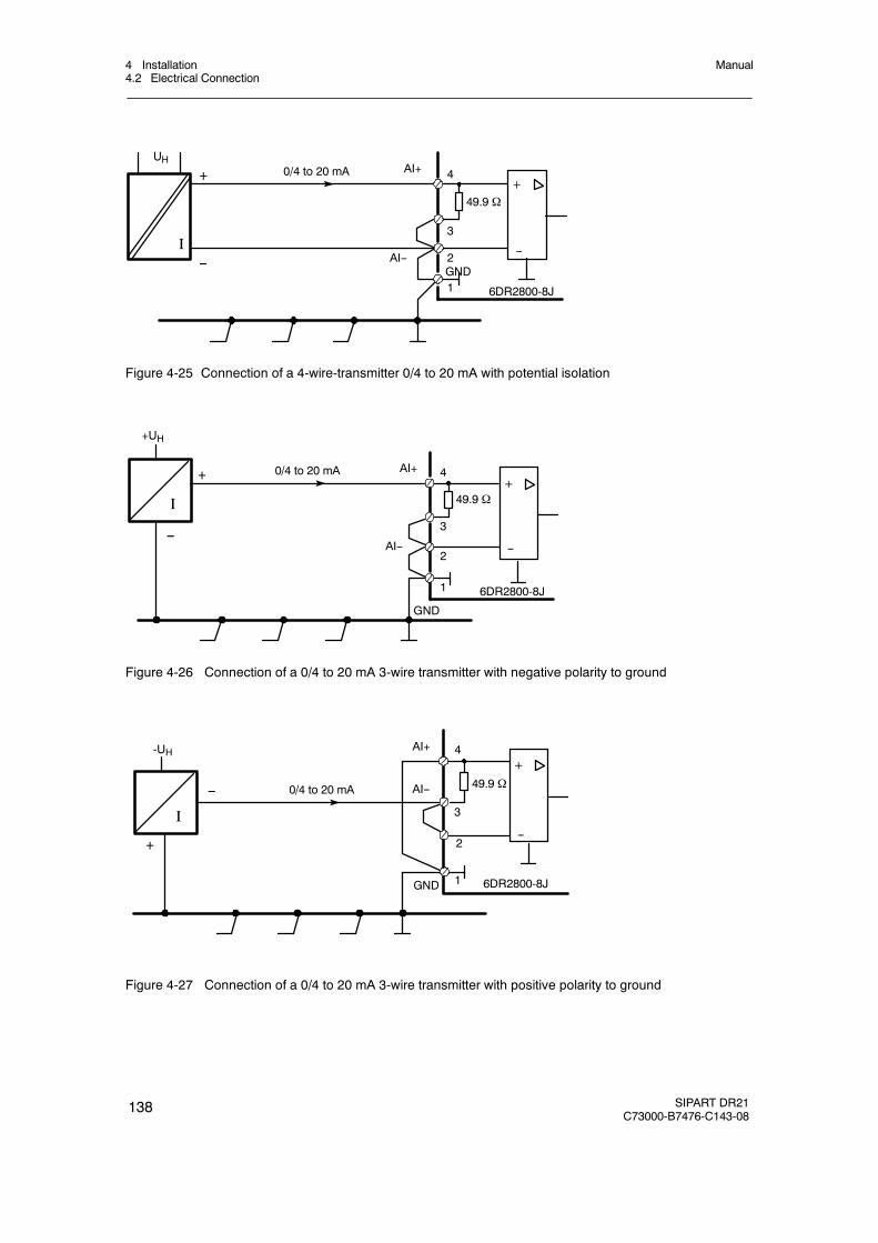
4 Installation4.2 Electrical Connection
Manual
138 SIPART DR21C73000-B7476-C143-08
I
0/4 to 20 mA+
UHAI+
AI--GND
--
49.9 Ω
6DR2800-8J1
2
3
4
--
+
Figure 4-25 Connection of a 4-wire-transmitter 0/4 to 20 mA with potential isolation
0/4 to 20 mA
+UH
AI+
AI--
GND
6DR2800-8J1
2
3
4+
--
49.9 ΩI
--
+
Figure 4-26 Connection of a 0/4 to 20 mA 3-wire transmitter with negative polarity to ground
0/4 to 20 mA
-UH AI+
AI--
GND 1
2
4+
--
49.9 Ω
3
6DR2800-8J
I
--
+
Figure 4-27 Connection of a 0/4 to 20 mA 3-wire transmitter with positive polarity to ground
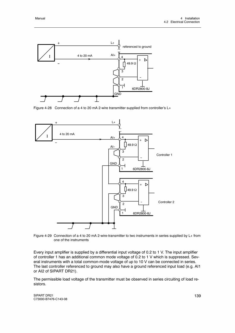
4 Installation4.2 Electrical Connection
Manual
SIPART DR21C73000-B7476-C143-08
139
4 to 20 mA AI+
L+
--
referenced to ground~~
49.9 Ω
6DR2800-8J
3
+
--
GND
2
1
4I
+
Figure 4-28 Connection of a 4 to 20 mA 2-wire transmitter supplied from controller’s L+
49.9 Ω
6DR2800-8J
3
+
--
GND2
44 to 20 mA
Controller 1
AI+
AI--
L+
~~
Controller 2
1
49.9 Ω
6DR2800-8J
3
+
--2
4
1
GND
+
--
I
Figure 4-29 Connection of a 4 to 20 mA 2-wire-transmitter to two instruments in series supplied by L+ fromone of the instruments
Every input amplifier is supplied by a differential input voltage of 0.2 to 1 V. The input amplifierof controller 1 has an additional common mode voltage of 0.2 to 1 V which is suppressed. Sev-eral instruments with a total common-mode voltage of up to 10 V can be connected in series.The last controller referenced to ground may also have a ground referenced input load (e.g. AI1or AI2 of SIPART DR21).
The permissible load voltage of the transmitter must be observed in series circuiting of load re-sistors.
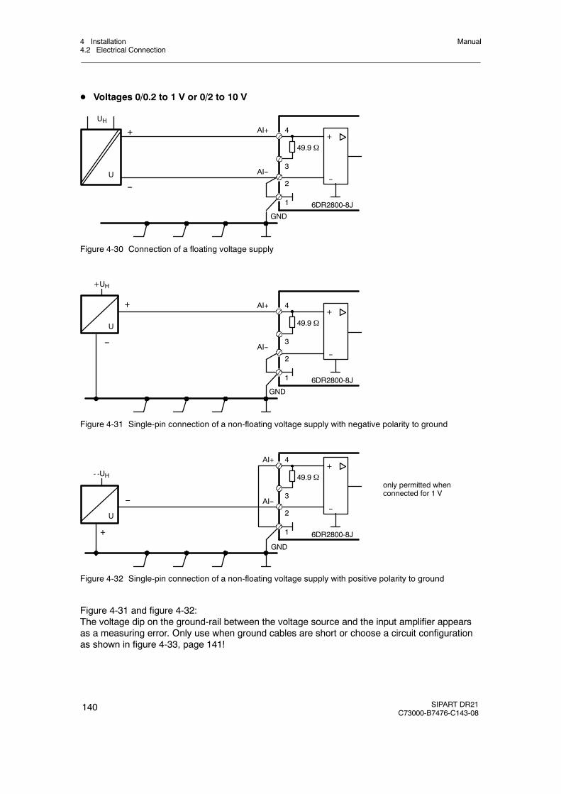
4 Installation4.2 Electrical Connection
Manual
140 SIPART DR21C73000-B7476-C143-08
D Voltages 0/0.2 to 1 V or 0/2 to 10 V
+
UHAI+
AI--
GND
--
49.9 Ω
6DR2800-8J1
2
3
4
U
--
+
Figure 4-30 Connection of a floating voltage supply
+
+UH
AI+
AI--
GND
--
49.9 Ω
6DR2800-8J1
2
3
4
U
--
+
Figure 4-31 Single-pin connection of a non-floating voltage supply with negative polarity to ground
+- -UH
AI+
AI--
GND
--
49.9 Ω
6DR2800-8J1
2
3
4
U
only permitted whenconnected for 1 V
--
+
Figure 4-32 Single-pin connection of a non-floating voltage supply with positive polarity to ground
Figure 4-31 and figure 4-32:The voltage dip on the ground-rail between the voltage source and the input amplifier appearsas a measuring error. Only use when ground cables are short or choose a circuit configurationas shown in figure 4-33, page 141!
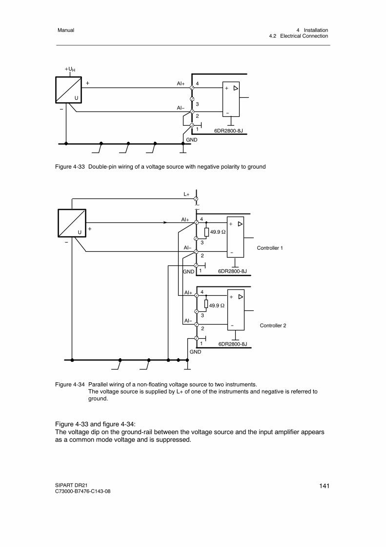
4 Installation4.2 Electrical Connection
Manual
SIPART DR21C73000-B7476-C143-08
141
+
+UH
AI+
AI--
GND
--
6DR2800-8J1
2
3
4
U
--
+
Figure 4-33 Double-pin wiring of a voltage source with negative polarity to ground
6DR2800-8J
3
+
--
GND
2
4
Controller 1
AI+
AI--
L+
~~
Controller 2
1
49.9 Ω
6DR2800-8J
3
+
--2
4
1
GND
+
--
AI--
U 49.9 Ω
AI+
Figure 4-34 Parallel wiring of a non-floating voltage source to two instruments.The voltage source is supplied by L+ of one of the instruments and negative is referred toground.
Figure 4-33 and figure 4-34:The voltage dip on the ground-rail between the voltage source and the input amplifier appearsas a common mode voltage and is suppressed.
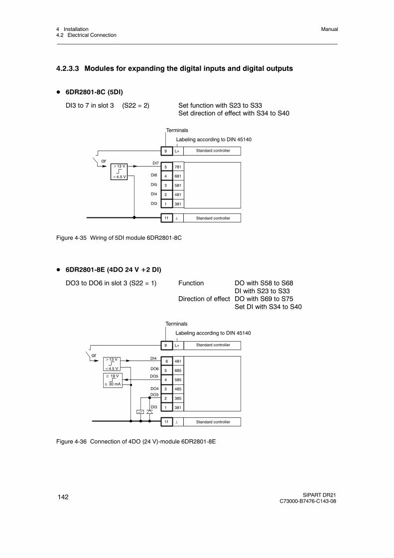
4 Installation4.2 Electrical Connection
Manual
142 SIPART DR21C73000-B7476-C143-08
4.2.3.3 Modules for expanding the digital inputs and digital outputs
D 6DR2801-8C (5DI)
DI3 to 7 in slot 3 (S22 = 2) Set function with S23 to S33Set direction of effect with S34 to S40
5 781
4 681
3 581
2 481
1 381
9 L+ Standard controller
11 ⊥ Standard controller
>13 V
<4.5 V
or
DI6
DI5
DI4
DI3
DI7
Terminals
Labeling according to DIN 45140
Figure 4-35 Wiring of 5DI module 6DR2801-8C
D 6DR2801-8E (4DO 24 V +2 DI)
DO3 to DO6 in slot 3 (S22 = 1) Function DO with S58 to S68DI with S23 to S33
Direction of effect DO with S69 to S75Set DI with S34 to S40
6 481
5 685
4 585
3 485
2 385
1 381
9 L+ Standard controller
11 ⊥ Standard controller
>13 V
<4.5 V
or
≥ 19 V
≤ 30 mA
DI4
DO6
DO5
DO4
DO3
DI3
Terminals
Labeling according to DIN 45140
Figure 4-36 Connection of 4DO (24 V)-module 6DR2801-8E
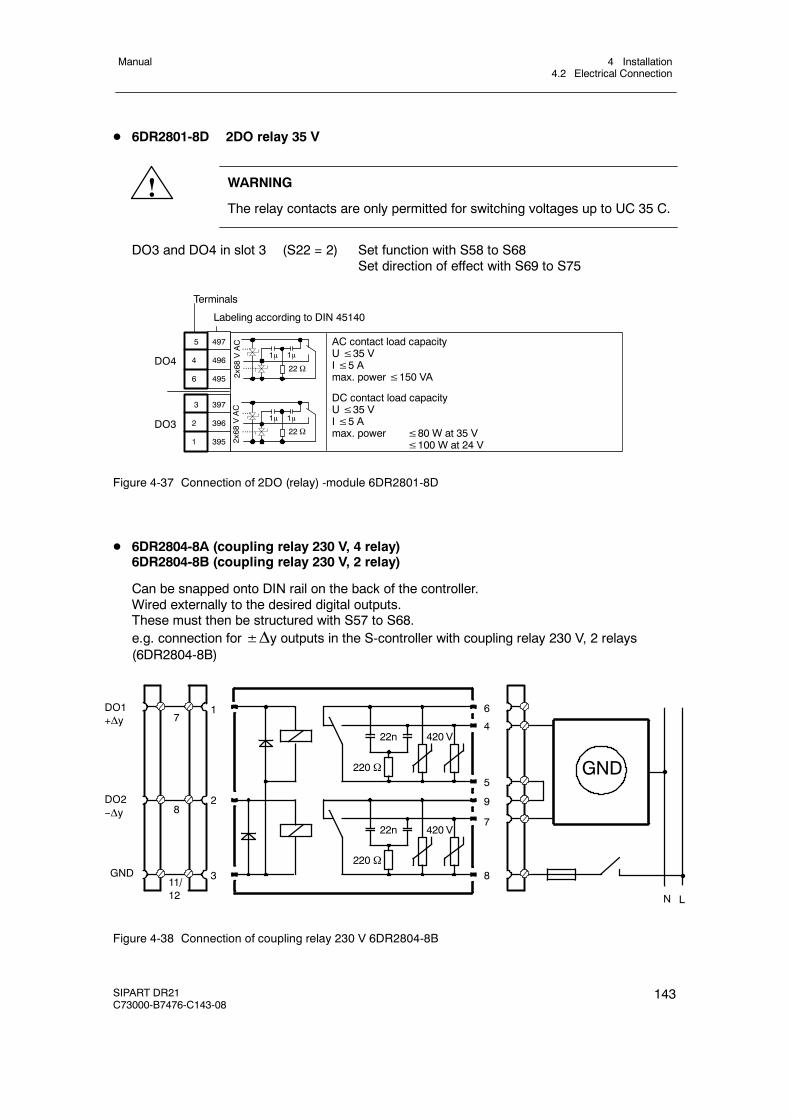
4 Installation4.2 Electrical Connection
Manual
SIPART DR21C73000-B7476-C143-08
143
D 6DR2801-8D 2DO relay 35 V
! WARNING
The relay contacts are only permitted for switching voltages up to UC 35 C.
DO3 and DO4 in slot 3 (S22 = 2) Set function with S58 to S68Set direction of effect with S69 to S75
5 497
4 496
6 495
Terminals
Labeling according to DIN 45140
DO4
2x68
VAC
1μ 1μ
22 Ω
3 397
2 396
1 395
DO31μ 1μ
22 Ω
....
......
AC contact load capacityU≤35 VI≤5 Amax. power≤150 VA
DC contact load capacityU≤35 VI≤5 Amax. power ≤80 W at 35 V
≤100 W at 24 V2x68
VAC ....
......
Figure 4-37 Connection of 2DO (relay) -module 6DR2801-8D
D 6DR2804-8A (coupling relay 230 V, 4 relay)6DR2804-8B (coupling relay 230 V, 2 relay)
Can be snapped onto DIN rail on the back of the controller.Wired externally to the desired digital outputs.These must then be structured with S57 to S68.e.g. connection for±Δy outputs in the S-controller with coupling relay 230 V, 2 relays(6DR2804-8B)
420 V
420 V
GND
DO1+Δy
DO2--Δy
220 Ω
22n
11/12
220 Ω
22n
N L
1
2
3
6
4
5
9
7
8GND
8
7
Figure 4-38 Connection of coupling relay 230 V 6DR2804-8B
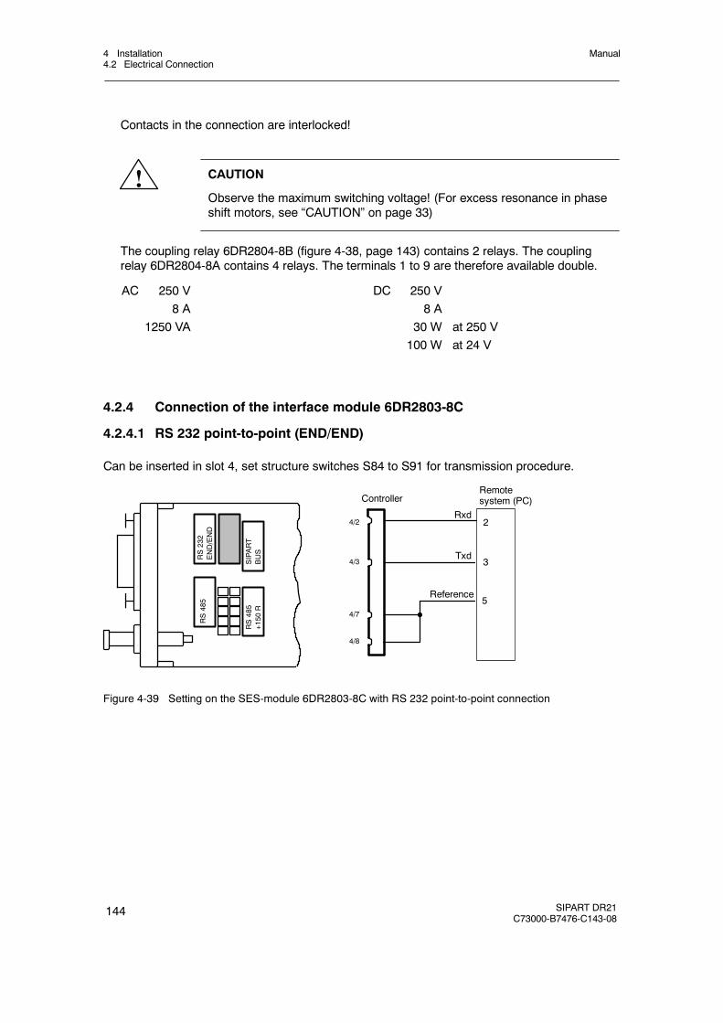
4 Installation4.2 Electrical Connection
Manual
144 SIPART DR21C73000-B7476-C143-08
Contacts in the connection are interlocked!
! CAUTION
Observe the maximum switching voltage! (For excess resonance in phaseshift motors, see “CAUTION” on page 33)
The coupling relay 6DR2804-8B (figure 4-38, page 143) contains 2 relays. The couplingrelay 6DR2804-8A contains 4 relays. The terminals 1 to 9 are therefore available double.
AC 250 V8 A
1250 VA
DC 250 V8 A
30 W at 250 V100 W at 24 V
4.2.4 Connection of the interface module 6DR2803-8C
4.2.4.1 RS 232 point-to-point (END/END)
Can be inserted in slot 4, set structure switches S84 to S91 for transmission procedure.
RS485
Rxd
ControllerRemotesystem (PC)
4/2
4/3
4/7
4/8
Txd
Reference
2
3
5
RS232
END/END
SIPART
BUS
RS485
+150
R
Figure 4-39 Setting on the SES-module 6DR2803-8C with RS 232 point-to-point connection

4 Installation4.2 Electrical Connection
Manual
SIPART DR21C73000-B7476-C143-08
145
4.2.4.2 RS 485 bus
Can be inserted in slot 4, set structure switches S84 to S91 for transmission procedure.
RS232
END/END
SIPART-
BUS
RS485
RS485
+150
R
Figure 4-40 Jumper settings SES-module 6DR2803-8C in RS 485 bus
Controller 32
RS 485 bus≤1200 mSES
Remote system
Controller 1
Controller 2
to
Rxd/Txd-B
Rxd/Txd-A
9-pin bus-plug for round cable: C73451-A347-D39
8 Rxd/Txd-A
8 Rxd/Txd-A
8 Rxd/Txd-A
3 Rxd/Txd-B
3 Rxd/Txd-B
3 Rxd/Txd-B
SES
SES
Jumper setting RS 485
Jumper setting RS 485 + 150R
Note line termination:
TheRS 485-busmust be terminatedwithits characteristic impedance. To do this,the terminating resistor in the ”last” bususer is switched by plugging the codingbridge appropriately.
.
Figure 4-41 RS 485-bus connection

4 Installation4.2 Electrical Connection
Manual
146 SIPART DR21C73000-B7476-C143-08
4.2.4.3 PROFIBUS-DP, 6DR2803-8P
Technical Data
Transmittable signals RS 485, PROFIBUS-DP-protocolTransmittable data Operating state, process variables, parameters and
structure switchesTransmission procedurePROFIBUS-/-DP-protocol.
According to DIN 19245, Part 1 and Part 3(EN 50 170)
Transmission speed 9.6 kbit/s to 1.5 Mbit/sStation number 0 to 125 (note software version)Time monitoring of the data communi-cation
Can be structured on the controller in connectionwith DP watchdog
Electrical isolation betweenRxd/Txd-P/-N and the controller
50 V UC common mode voltage
Test voltage 500 V ACRepeater-control signal CNTR-P TTL-level with 1 TTL loadSupply voltage VP (5 V) 5 V --0.4 V/+0.2 V; short-circuit-proofLine lengths, per segment at1.5 MBit/s
200 m; for other data see manual “ET 200 Distribu-ted I/O System”, order no. 6ES5 998-3ES22.
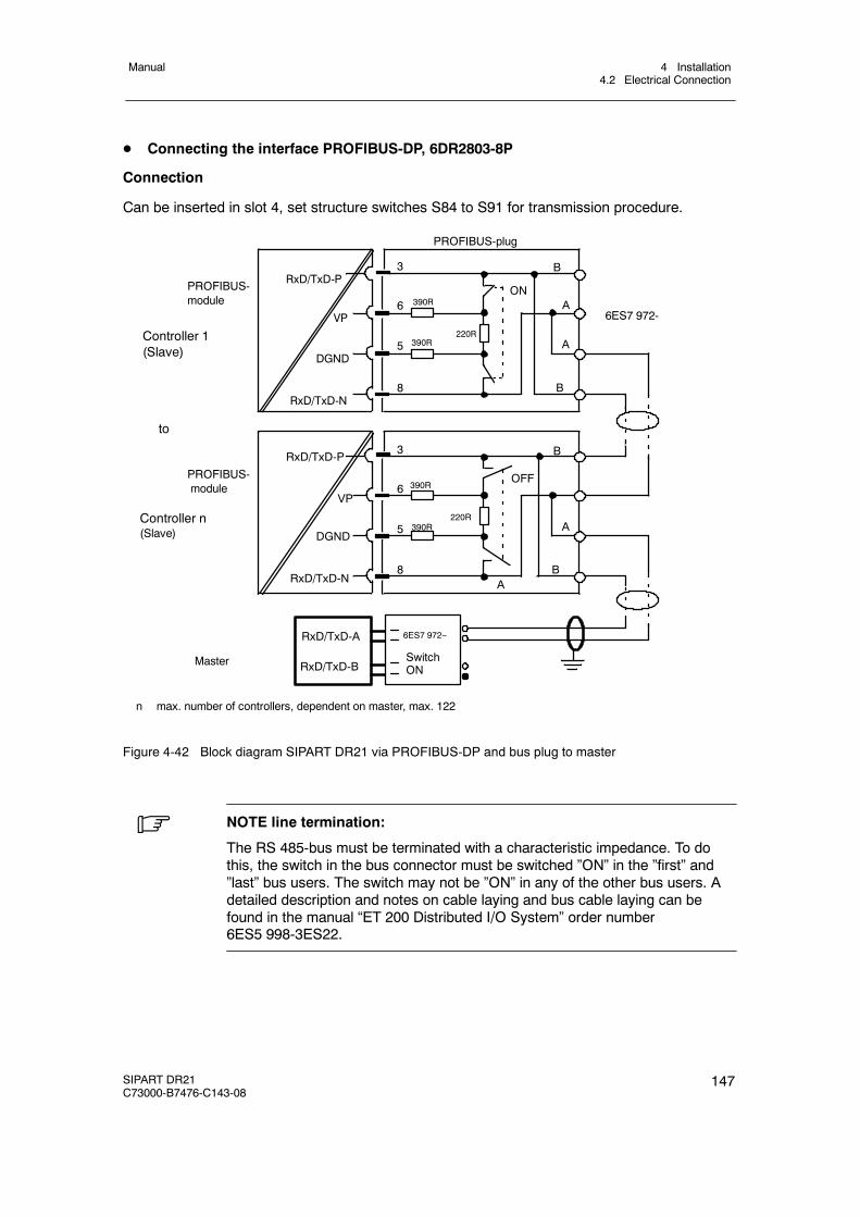
4 Installation4.2 Electrical Connection
Manual
SIPART DR21C73000-B7476-C143-08
147
D Connecting the interface PROFIBUS-DP, 6DR2803-8P
Connection
Can be inserted in slot 4, set structure switches S84 to S91 for transmission procedure.
B
A
A
RxD/TxD-P
VP390R
3
6ON
DGND5
220R390R
PROFIBUS-module
PROFIBUS-plug
Controller 1(Slave)
RxD/TxD-N8
B
Controller n(Slave)
to
RxD/TxD-P
VP390R
3
6OFF
DGND5
220R390R
RxD/TxD-N8
B
A
A
B
PROFIBUS-module
RxD/TxD-A
RxD/TxD-BMaster
n max. number of controllers, dependent on master, max. 122
6ES7 972-
6ES7 972--
SwitchON
Figure 4-42 Block diagram SIPART DR21 via PROFIBUS-DP and bus plug to master
. NOTE line termination:
The RS 485-bus must be terminated with a characteristic impedance. To dothis, the switch in the bus connector must be switched ”ON” in the ”first” and”last” bus users. The switch may not be ”ON” in any of the other bus users. Adetailed description and notes on cable laying and bus cable laying can befound in the manual “ET 200 Distributed I/O System” order number6ES5 998-3ES22.

4 Installation4.2 Electrical Connection
Manual
148 SIPART DR21C73000-B7476-C143-08

5 Operation5.1 General
Manual
SIPART DR21C73000-B7476-C143-08
149
5 Operation
5.1 General
D Operating modes
The SIPART DR21 is operated exclusively and fully with the operating keys on the frontmodule. The function of the operating panel can be switched between three main levels:
Process operationmode
The process values x, w, y and the controller status are displayed,the process operation mode can be controlled by the operating keys.
Selection level Here the list is selected which can be changed or activated in theconfiguration mode. These are the following lists:
onPA Online parameters(AdAP) Start adaptationoFPA Offline parametersStrS Structure switches(CAE3) Set UNI-moduleAPSt all preset
The lists for onPA, oFPA, StrS and APST are always displayed inthe selection mode.The lists for AdAP and CAE3 only appear in the display when theyhave been selected by structure switches.
Configurationmodes
Settings are made in the selected list or functions are activated.
Some of the keys and displays on the front module are assigned different control and displayfunctions when the operating mode is changed. See the description of the respective mainlevel for details.
D Operating locks
Operation of the controller or access to the selection or configuration modes can be lockedby digital signals. The following blocking steps are possible:
bLb Blocking, OperationThe complete operation of the controller is blocked. Exception: Switching over thew/x digital display. ”bLb” appears in the display on pressing the operating keys.
bLS Blocking, StructuringBlocking the lists AdAP, oFPA, StrS, CAE3 and APSt.Only the list for onPA is accessible. ”bLS” appears in the display when the blockedmode is called
bLPS Blocking, Parameterization and StructuringThe complete selection and configuration mode is blocked. The process operationmode is free. ”bLPS” appears in the display when the blocked mode is called

5 Operation5.2 Process operation mode
Manual
150 SIPART DR21C73000-B7476-C143-08
D Behavior of the controller in the factory setting
SIPART DR21 operates as a fixed value controller in the factory setting.For safety reasons the online parameters, “proportional action factor Kp” and the “integralaction time Tn” are preset to uncritical values.
It is absolutely essential that these parameters be set to suit the requirements of yourcontrolled system.
5.2 Process operation mode
D Control elements
See page 5 for the control and display elements.
The operation of the SIPART DR21 in process mode requires no detailed explanation due tothe design and color scheme of the operating panel, the control elements and the labeling.
D Actual value
The red vertical LED bargraph (1) and -- with the red x LED (5) -- of the four-digit digitaldisplay (3) lit steadily indicate the actual value.
D Setpoint
The green vertical LED bargraph (2) and -- with the green w LED (4) -- of the four-digit digitaldisplay (3) lit steadily indicate the setpoint. The green Internal/External key (16) switchesbetween the internal and external setpoint. The internal setpoint is set with the green± Δ wadjusting keys (14), (15). The green internal LED (17) signals operation with the internal set-point, C LED (18) also lights green when there is no CB control signal.
However, a change in the setpoint setting is only possible when the green LEDs (4 and 17)signal that the four-digit display shows the setpoint and Internal operation is active.
D Manipulated variable
In the y display (9) the manipulated variable y or, according to the position of the structureswitch S54, the position feedback y R or split range y1/y2 is always displayed independentlyof the variable output at the analog output AO.
The yellow H/A-key (11) is used to switch between manual and automatic operation. Theyellow manual LED (12) signals by lighting steadily or flashing that manual operation hasbeen activated. Lighting up of the yellow y external LED (13) signals an external interventionin the manipulated variable, i.e. a tracking (DDC) , safety or blocking operation. The manipu-lated variable generally displayed in the y digital display (9) can be adjusted with the yellow±Δy keys (7), (8) in manual operation. The±Δy LEDs (10) indicate the output of the posi-tioning increments in all operating modes of the S-controller.
The alarm LEDs (20) and signal exceeding or dropping below the limit values.
5 Operation5.2 Process operation mode
Manual
SIPART DR21C73000-B7476-C143-08
151
The adaptation LED (19) signals the progress of the parameter optimization during theadaptation process by lighting steadily or flashing.
D Adaptation
The adaptation LED (19) signals the active adaptation procedure by flashing.
D Lamp test
If the button (6) is kept pressed for longer than 5 s, all LEDs on the front of the controller aredriven independently of the respective display until the button is released again. The originaldisplay position is restored after checking the lamp function.
D Display of the software version
The software for the SIPART DR21 controller will be improved based on new knowledge ifrequired. The respective version of the software is stored in the EPROM with identificationand can be called as follows:
" Run the lamp test with the button (6),
" Then press the button (16) additionally. On the digital displays (3) and (9) theidentification can now be read off for the controller software version.
D Alarms
The red alarm LEDs (20) signal exceeding or dropping below the limit values which can beset with the offline parameters A1 to A4. The assignment to the variables to be monitored ismade with the structure switches S76, S77, their display with S80.
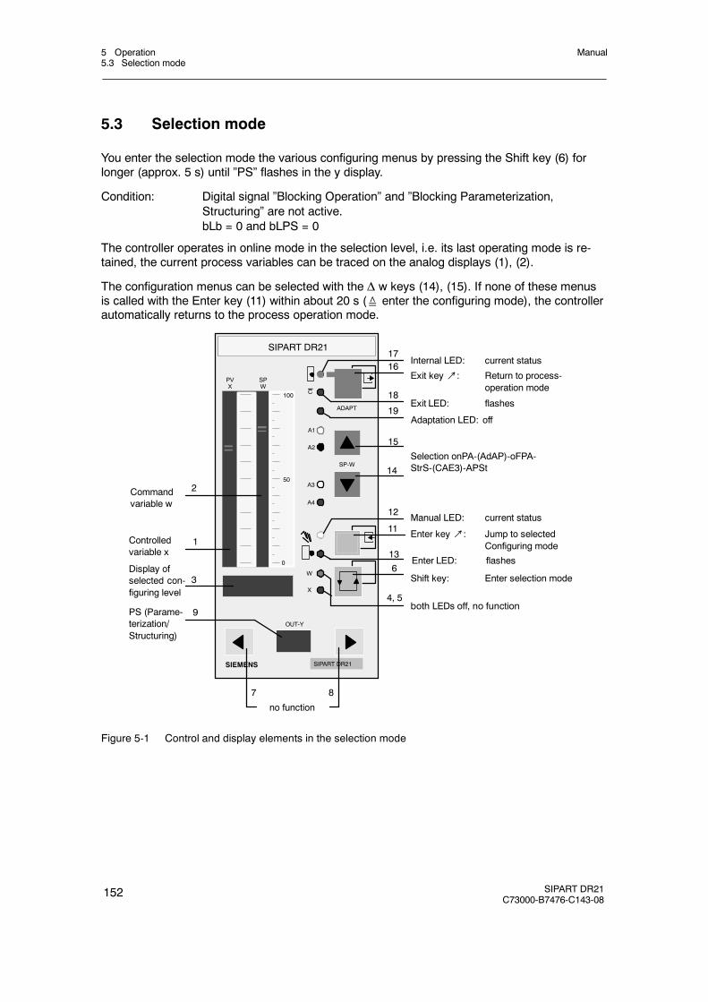
5 Operation5.3 Selection mode
Manual
152 SIPART DR21C73000-B7476-C143-08
5.3 Selection mode
You enter the selection mode the various configuring menus by pressing the Shift key (6) forlonger (approx. 5 s) until ”PS” flashes in the y display.
Condition: Digital signal ”Blocking Operation” and ”Blocking Parameterization,Structuring” are not active.bLb = 0 and bLPS = 0
The controller operates in online mode in the selection level, i.e. its last operating mode is re-tained, the current process variables can be traced on the analog displays (1), (2).
The configuration menus can be selected with the Δ w keys (14), (15). If none of these menusis called with the Enter key (11) within about 20 s (≙ enter the configuring mode), the controllerautomatically returns to the process operation mode.
SIPART DR21
SIPART DR21SIEMENS
SP-W
OUT-Y
C
PVX
A1
A2
A3
A4
ADAPT
100
50
0
W
X
SPW
no function
3
1
2
7 8
9
14
15
Selection onPA-(AdAP)-oFPA-StrS-(CAE3)-APSt
Commandvariable w
Controlledvariable x
Adaptation LED: off
Shift key: Enter selection mode
PS (Parame-terization/Structuring)
Display ofselected con-figuring level
Exit key↗: Return to process-operation mode
Exit LED: flashes
Internal LED: current status
Manual LED: current status
Enter key↗: Jump to selectedConfiguring mode
both LEDs off, no function4, 5
6
19
11
12
13
1617
18
Enter LED: flashes
Figure 5-1 Control and display elements in the selection mode

5 Operation5.3 Selection mode
Manual
SIPART DR21C73000-B7476-C143-08
153
Exit key (16)
1)bLb = 1 or bLPS = 1bLPS = 0
Enter key (11)
Shift key (6)up to approx. 5 s
Process operation mode
Operating and MonitoringbLb = 0
onPA
Exit-key (16)
PS in they display flashes
Online-parameterssee chapter 5.4.2, page 155
Adaptationsee chapter 5.4.3, page 156
Parameterization mode (online)
AdAP, only appearsat S48 > 0
bLb or bLPS in the w/x-display,PS in the y display flashes
At bLb = 1 no operationat all is possible.
oFPA
BLS = 1
BLS = 0
StrS
CAE3, only appearsat S6 > 3
APSt
Δw key (14, 15)
Δw key (14, 15)
Δw key (14, 15)
Δw key (14, 15)
Selection mode
Offine parameterssee
chapter 5.4.4, page 163
Structure switchessee chapter 5.4.5, page 165
CAE-menusee chapter 5.4.6, page 173
All Preset (sets controller tofactory setting)
see chapter 5.4.7, page 178
Enter key (11)
Exit key (16)
Exit key (16)
Exit key (16)
Exit key (16)
Exit key (16)
Structuring modes (offline)
Release of theShift key (6)
Enter key (11)up to (approx. 3 s)
Enter key (11)up to (approx. 3s)
Enter key (11)up to (approx. 3 s)
Enter key (11)up to (approx. 3 s)
Δw key (14, 15)
Δw key (14, 15)
1) automatic return if there is no Enter function to a parameterization- or structuring mode within 20 s.
Figure 5-2 Overview selection mode

5 Operation5.4 Configuration modes
Manual
154 SIPART DR21C73000-B7476-C143-08
5.4 Configuration modes
5.4.1 General, Online and Offline modes
The settings in the configuration modes onPA and AdAP and the selection in the selectionmode (see fig. 5-2, page 153 takes place in online mode, i.e. the controller continues operatingin its last mode. The onPA and AdAP modes are entered directly from the selection modes bypressing the Enter key (11). The analog x display (1) and w display (2) still display the processimage so that the reaction of the controlled system to parameter changes can be read off di-rectly. The Internal LED (17) and Manual LED (12) and the Alarm LEDs A1 to A4 indicate thecurrent operating state. The Internal/External key (16) becomes the Exit key, the correspondingCLED (18) indicates ready to exit, i.e. every time the LED flashes, pressing the Exit key jumpsfrom the selected mode to the next level up in the hierarchy.
The Automatic /Manual key (11) becomes the Enter key, the corresponding y external LED (13)indicates ready to enter, i.e. whenever the LED flashes, pressing the Enter key jumps to thenext level down in the hierarchy.
Press the Enter key (11) for 3 s to go from the preselection mode to the offline mode with theoFPA, StrS, APSt and CAE3 menus The user stays offline when returning (from offline menu)to the preselection mode. When subsequently jumping to another off line mode the three-sec-ond time condition is irrelevant. The three-second time condition for entering an offline menu isonly valid again after exiting the offline mode by selecting an online mode with the onPA andAdap menus or exiting the preselection mode. The controller switches into the absolutemanual mode (offline mode), i.e. the last manipulated variable of the online mode is retained(in K-controllers the last manipulated variable, in S-controllers no positioning increments areoutput). A change in the manipulated variable using the±Δy-keys (7), (8) is not possible, thecontrol signals N (DDC), Si and±yBL are not effective. The analog output, the digital outputsand the alarm LEDs A1 to A4 are held at the last value or status. To identify the offline mode,the analog w display shows a striped pattern and the manual LED (12) lights up. The absolutemanual mode is retained when returning to the parameterization preselection mode (onlinemode) or the process operation mode from the structuring preselection mode with the Exit key(16). This also applies if only automatic operation has been preselected with S51 = 1. The con-troller must also be reactivated in the process operation mode for safety reasons by switchingto automatic operation.The analog x display (1) continues to display the controlled variable x during offline mode, theInternal LED (17) the current status. The control elements keys (11), (16) and the LEDs (12),(13), (17), (18) have the same function as in the online configuration modes.
If the control signal bLPS = 1, parameterization and structuring is blocked, no PS (w/x and ydisplays) appears when you press the Shift key.
If the control signal bLS = 1, structuring is blocked. Only onPA and AdAP appear in the selec-tion mode.
. NOTE
Please note that changed parameters and structure switch settings are onlytransferred to the failsafe EEPROM after returning to the process operationmode.

5 Operation5.4 Configuration modes
Manual
SIPART DR21C73000-B7476-C143-08
155
5.4.2 Configuration mode online-parameters onPA
The parameters for which the effect on the process when they are adjusted must be observeddirectly are arranged in the parameterization mode onPA. The other parameters are arranged inthe structuring mode oFPA. After pressing the Enter key (11) in the onPA configuration mode,the first parameter of table 5-1 Filter time constant tF in the y display (9) appears with its cur-rent value in the w/x display (3) the first time the mains is switched on. Otherwise the parameterselected last the last time the onPA mode was exited appears. With the Δy keys (7), (8) the pa-rameters are selected, with keys Δw (14), (15) the value is set. The parameters with a largenumber range can be adjusted in fast mode.
First select the adjustment direction with one Δw key and then switch on the rapid action bysimultaneously pressing the other Δw key.
onPA Online Parameter list
parameters y Num. w/x display Unit
Parametername Min. Max.
Factorysetting
Filter time constantfor filter xd (adaptive)Derivative-action gain VvProportional gain factor KpIntegral-action time TnDerivative-action time TvResponse thresholdOperating point
tF
uucPtntvAHY0
off/1.000
0.1000.1001.000
off/1.0000.0
Auto/0.0
1000
10.00100.09984299210.0100.0
1.000
5.0000.1009984off0.0
Auto
s
11ss%%
Output start (YA≤YE)Output endy actuating time open/period heatingy actuating time closed/period cooling
YAYEtPtM
-10.0-10.0
off/0.100off/0.100
110.0110.010001000
-5.0105.01.0001.000
%%ss
Actuating pulse pauseActuating pulse length
tA 2)
tE 2)2020
1) 6001) 600
200200
msms
Filter time AI1Filter time AI2Filter time AI3Filter time AI4
t1t2t3t4
off/0.100off/0.100off/0.100off/0.100
1000100010001000
1.0001.0001.0001.000
ssss
Constant c1Constant c2Constant c3Constant c4Constant c5Constant c6Constant c7
c1c2c3c4c5c6c7
-1.999-1.999-1.999-1.999-1.999-9.99
+1.000
9.9999.9999.9999.9999.9999.999.999
0.0000.0000.0001.0000.0000.001.000
Display refresh rate dr 0.100 9.900 1.000 s1) In two-position controller S2 = 1 up to 9980 ms2) In two-position controllers: tA = shortest turn-on pulse and shortest pulse pause in the cooling branch
tE = shortest turn-on pulse and shortest pulse duration in the heating branch
Table 5-1 Online selection list
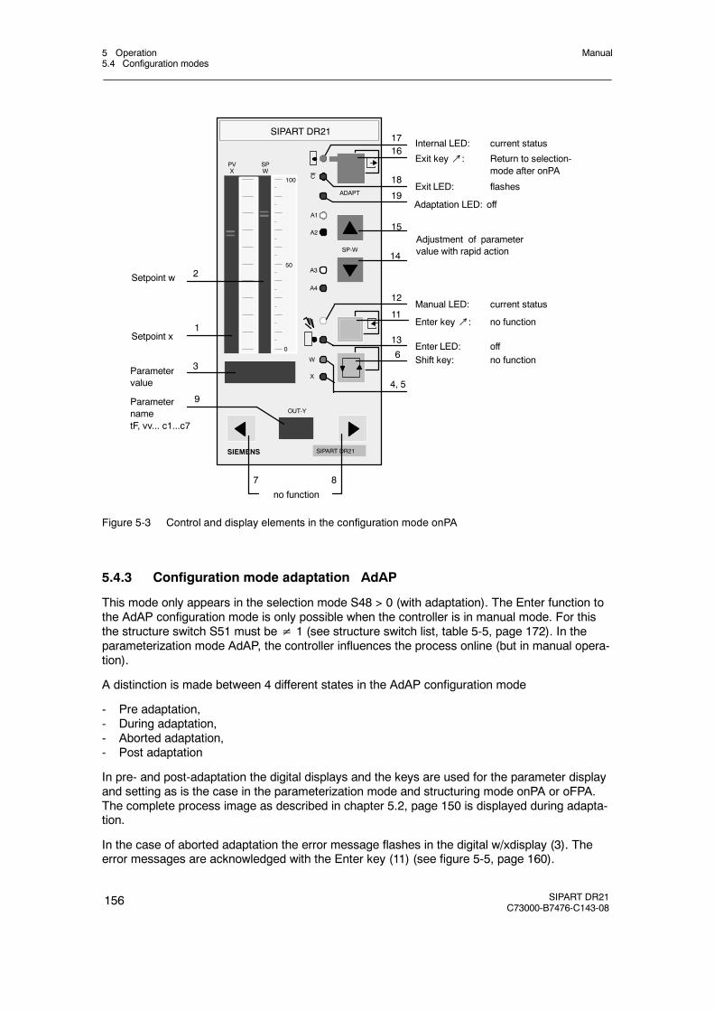
5 Operation5.4 Configuration modes
Manual
156 SIPART DR21C73000-B7476-C143-08
SIPART DR21
SIPART DR21SIEMENS
SP-W
OUT-Y
C
PVX
A1
A2
A3
A4
ADAPT
100
50
0
W
X
SPW
no function
3
1
2
7 8
9
14
15
4, 5
6
19
11
12
13
1617
18
Adjustment of parametervalue with rapid action
Setpoint w
Setpoint x
Adaptation LED: off
Shift key: no function
ParameternametF, vv... c1...c7
Parametervalue
Exit key↗: Return to selection-mode after onPA
Exit LED: flashes
Internal LED: current status
Manual LED: current status
Enter key↗: no function
Enter LED: off
Figure 5-3 Control and display elements in the configuration mode onPA
5.4.3 Configuration mode adaptation AdAP
This mode only appears in the selection mode S48 > 0 (with adaptation). The Enter function tothe AdAP configuration mode is only possible when the controller is in manual mode. For thisthe structure switch S51 must be≠ 1 (see structure switch list, table 5-5, page 172). In theparameterization mode AdAP, the controller influences the process online (but in manual opera-tion).
A distinction is made between 4 different states in the AdAP configuration mode
- Pre adaptation,- During adaptation,- Aborted adaptation,- Post adaptation
In pre- and post-adaptation the digital displays and the keys are used for the parameter displayand setting as is the case in the parameterization mode and structuring mode onPA or oFPA.The complete process image as described in chapter 5.2, page 150 is displayed during adapta-tion.
In the case of aborted adaptation the error message flashes in the digital w/xdisplay (3). Theerror messages are acknowledged with the Enter key (11) (see figure 5-5, page 160).
5 Operation5.4 Configuration modes
Manual
SIPART DR21C73000-B7476-C143-08
157
D Conditions for adaptation
- The controller must be in a stationary condition, i.e. the controlled variable x must beconstant.
- The system to be adapted must be a system with compensation, i.e. the manipulatedvariable step in the adaptation must lead to a constant controlled variable x.
- No adaptation can be performed in stepper controllers with S2 = 2 and firmware versionA04 or earlier. Adaptation here is only possible in connection with the external feedback(jumper setting via S19 to yR). As of firmware A05 or higher the change in the manipu-lated variable required for adaptation is determined from the drive runtime. Accurate set-ting of the parameters tP and tM is presumed.
- It is recommended to start the adaptation from the y value (operating point) usual for thistype of control circuit.
D Pre adaptation
The controller must be switched to manual (key (11)) before entering the selection mode.The ”AdAP” menu can only be selected at S48 > 0. It is called with the Enter key (11). Theadaption LED (19) is off and indicates readiness for adaptation. First the parameters for thepresettings (tU, dPv, dY) are displayed. They must be set according to the desired step com-mand. Then the old online parameters appear on the displays (see table 5-1, page 155) withtheir respective value. This can only be preset in the onPA mode.
NOTICE
Make sure the set step command causes no damage to the process controlsystem. The control loop is not closed during the adaptation. The adaptationprocedure is unsuitable for systems without compensation (systems with inte-gral behaviour).
The selection of the parameters is made with the keys (7), (8), the setting of the values withthe keys (14), (15). The LED (13) flashes when ”Strt” appears in the w/x display (3). Adapta-tion can now be started with Enter (11).
D During adaptation
The adaptation LED (19) flashes indicating that the adaptation is in progress. The processcan be monitored over the whole process display. Keys (7), (8), (14) and (15) have no func-tion. The w/x display (3) can be switched over with the key (6) depending on the position ofS81. The adaptation can be aborted manually with the key (16).
D Aborted adaptation
The current adaptation can be aborted manually or automatically by the error monitor.
The adaptation LED (19) is off indicating readiness for adaptation after error acknowledge-ment. The Enter LED (13) flashes as a request for error acknowledgement.
Manual abortion can be activated in the event of danger by pressing the Exit key (16). Theprogram then jumps to the selection mode after AdAP. From there you can return to the pro-cess operation level by pressing the Exit key (16) again. The controller is in manual oper-ation and the manual manipulated variable can be adjusted.
5 Operation5.4 Configuration modes
Manual
158 SIPART DR21C73000-B7476-C143-08
Automatic abortion is effected by the error monitors (see table 5-3, page 162). The errormessages are displayed on the digital w/xdisplay. The error message is acknowledged bypressing the Enter key (11), the configuration mode AdAP is retained, tU is displayed, thepresettings can be corrected if necessary. The adaptation is aborted by the signals N (DDC),Si and±yBL. Abortion by the SES control signals N ES (DDC), SiES,±yBLES can be pre-vented by Internal operation.
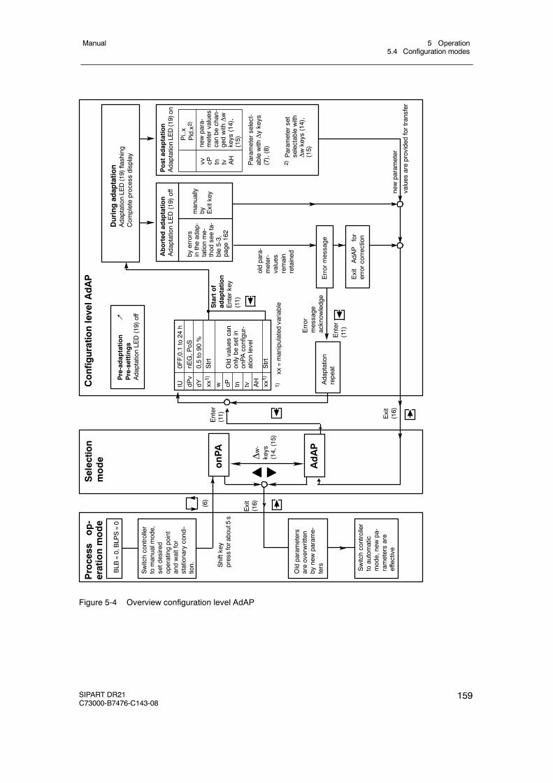
5 Operation5.4 Configuration modes
Manual
SIPART DR21C73000-B7476-C143-08
159
Process
op-
erationmode
BLB
=0,BLP
S=0
Shiftkey
pressforabout5s
Selection
mode
onPA
AdAP
ConfigurationlevelAdAP
Pre-adaptation
↗Pre-settings
AdaptationLE
D(19)off
(6)
Exit
(16)
Enter
(11) Exit
(16)
Δw-
keys
(14,(15)
Duringadaptation
AdaptationLE
D(19)flashing
Com
pleteprocessdisplay
Param
eterselect-
ablewithΔykeys
(7),(8)
2)Param
eterset
selectablewith
Δwkeys
(14),
(15)
Startof
adaptation
Enterkey
(11)
1)xx
=manipulated
variable
oldpara-
meter-
values
remain
retained
Enter
(11)Error
message
acknow
ledge
Adaptation
repeat
Aborted
adaptation
AdaptationLE
D(19)off
byerrors
intheadap-
tationme-
thod
seeta-
ble5-3,
page
162
manually
by Exitkey
Errormessage
ExitAdA
Pfor
errorcorrection
Switchcontroller
toautomatic
mode,newpa-
rametersare
effective
Oldparameters
areoverwritten
bynewparame-
ters
Switchcontroller
tomanualm
ode,
setdesired
operatingpoint
andwaitfor
stationarycondi-
tion.
tU0FF,0.1to24
hdP
vnE
G,P
oSdY
0,5to90
%xx
1)Strt
w cP tn tv AH
xx1)
Strt
Oldvalues
can
onlybe
setin
onPA
configur-
ationlevel
Postadaptation
AdaptationLE
D(19)on
vv cP tn tv AH
newpara-
metervalues
canbe
chan-
gedwithΔw
keys
(14),
(15)Pi..x
Pid.x2)
newparameter
values
areprovided
fortransfer
Figure 5-4 Overview configuration level AdAP
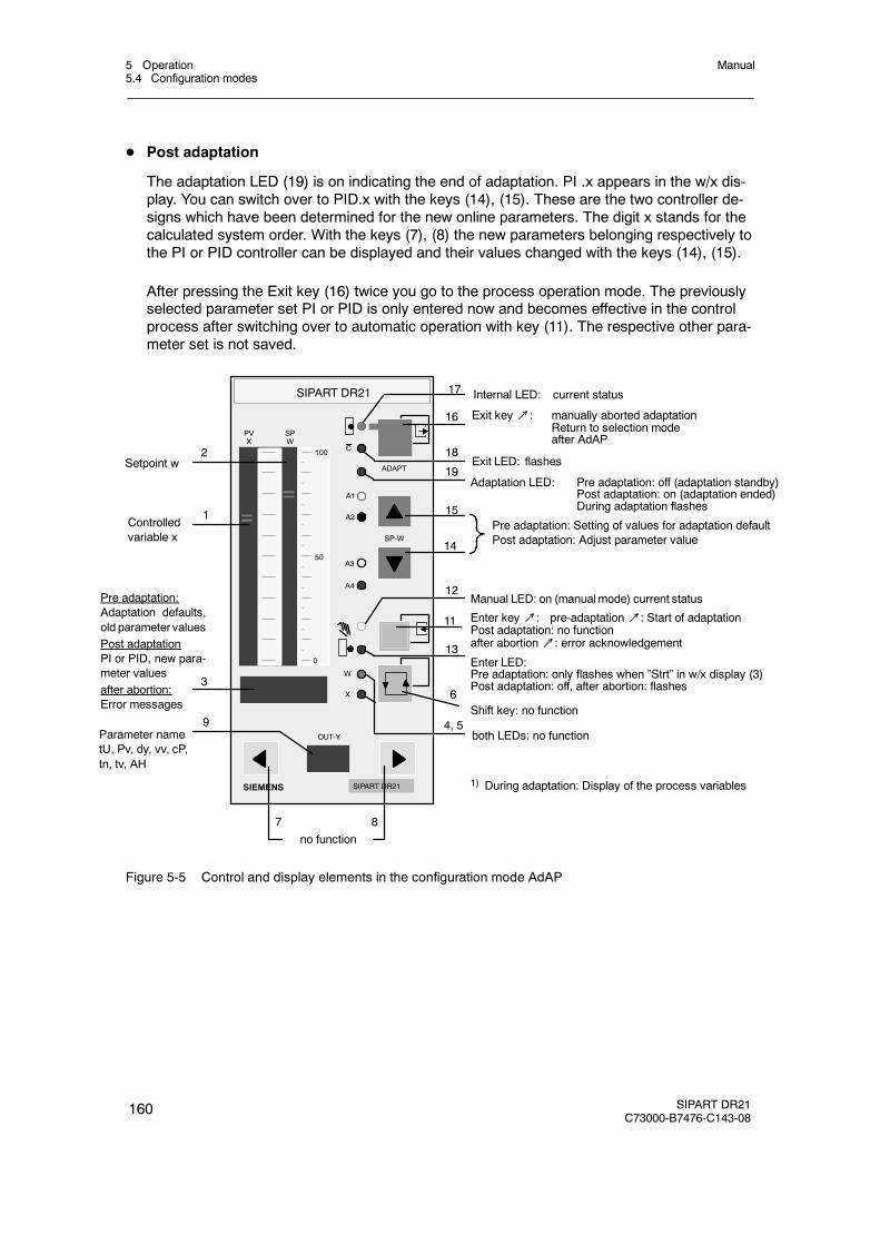
5 Operation5.4 Configuration modes
Manual
160 SIPART DR21C73000-B7476-C143-08
D Post adaptation
The adaptation LED (19) is on indicating the end of adaptation. PI .x appears in the w/x dis-play. You can switch over to PID.x with the keys (14), (15). These are the two controller de-signs which have been determined for the new online parameters. The digit x stands for thecalculated system order. With the keys (7), (8) the new parameters belonging respectively tothe PI or PID controller can be displayed and their values changed with the keys (14), (15).
After pressing the Exit key (16) twice you go to the process operation mode. The previouslyselected parameter set PI or PID is only entered now and becomes effective in the controlprocess after switching over to automatic operation with key (11). The respective other para-meter set is not saved.
SIPART DR21
SIPART DR21SIEMENS
SP-W
OUT-Y
C
PVX
A1
A2
A3
A4
ADAPT
100
50
0
W
X
SPW
no function
3
1
2
7 8
9
14
15
4, 5
6
19
11
12
13
16
17
18Setpoint w
Controlledvariable x
Adaptation LED: Pre adaptation: off (adaptation standby)Post adaptation: on (adaptation ended)During adaptation flashes
Shift key: no function
Exit key↗: manually aborted adaptationReturn to selection modeafter AdAP
Exit LED: flashes
Internal LED: current status
Manual LED: on (manualmode) current status
Enter key↗: pre-adaptation↗: Start of adaptationPost adaptation: no functionafter abortion↗: error acknowledgement
both LEDs: no function
Enter LED:Pre adaptation: only flashes when ”Strt” in w/x display (3)Post adaptation: off, after abortion: flashes
Pre adaptation: Setting of values for adaptation defaultPost adaptation: Adjust parameter value
Parameter nametU, Pv, dy, vv, cP,tn, tv, AH
Pre adaptation:Adaptation defaults,old parameter valuesPost adaptationPI or PID, new para-meter valuesafter abortion:Error messages
1) During adaptation: Display of the process variables
Figure 5-5 Control and display elements in the configuration mode AdAP
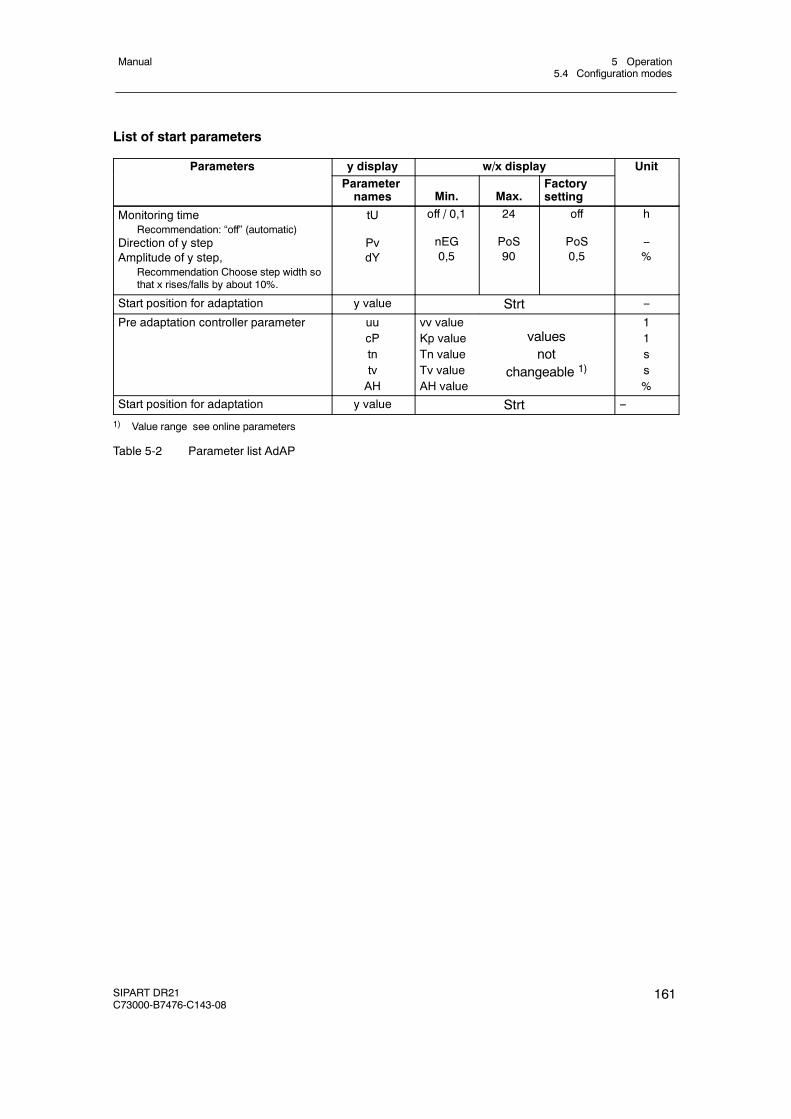
5 Operation5.4 Configuration modes
Manual
SIPART DR21C73000-B7476-C143-08
161
List of start parameters
Parameters y display w/x display UnitParameternames Min. Max.
Factorysetting
Monitoring timeRecommendation: “off” (automatic)
Direction of y stepAmplitude of y step,
Recommendation Choose step width sothat x rises/falls by about 10%.
tU
PvdY
off / 0,1
nEG0,5
24
PoS90
off
PoS0,5
h
--%
Start position for adaptation y value Strt --
Pre adaptation controller parameter uucPtntvAH
vv valueKp valueTn valueTv valueAH value
valuesnot
changeable 1)
11ss%
Start position for adaptation y value Strt --
1) Value range see online parameters
Table 5-2 Parameter list AdAP
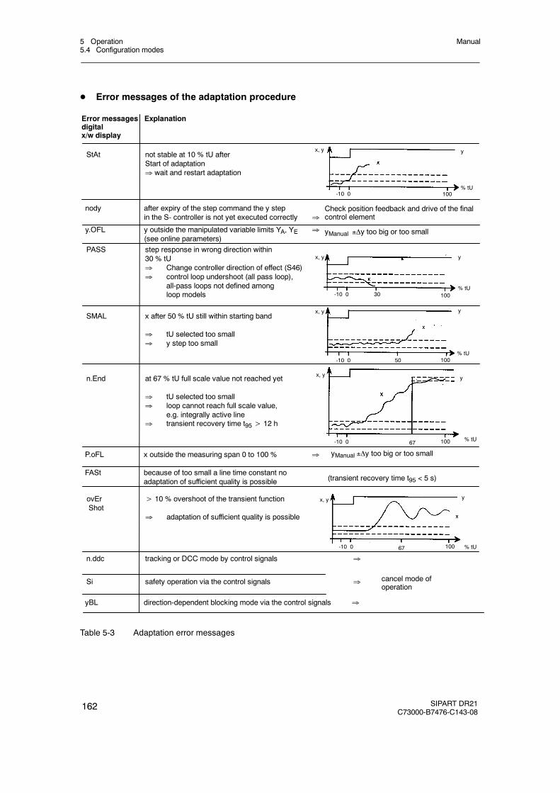
5 Operation5.4 Configuration modes
Manual
162 SIPART DR21C73000-B7476-C143-08
D Error messages of the adaptation procedure
yBL direction-dependent blocking mode via the control signals ⇒
n.ddc tracking or DCC mode by control signals ⇒
ovEr > 10 % overshoot of the transient functionShot
⇒ adaptation of sufficient quality is possible
FASt because of too small a line time constant noadaptation of sufficient quality is possible
P.oFL x outside the measuring span 0 to 100 % ⇒
n.End at 67 % tU full scale value not reached yet
⇒ tU selected too small⇒ loop cannot reach full scale value,
e.g. integrally active line⇒ transient recovery time t95> 12 h
SMAL x after 50 % tU still within starting band
⇒ tU selected too small⇒ y step too small
PASS step response in wrong direction within30 % tU⇒ Change controller direction of effect (S46)⇒ control loop undershoot (all pass loop),
all-pass loops not defined amongloop models
y.OFL y outside the manipulated variable limits YA, YE ⇒(see online parameters)
nody after expiry of the step command the y stepin the S- controller is not yet executed correctly ⇒
Error messages Explanationdigitalx/w display
yManual y too big or too small
Check position feedback and drive of the finalcontrol element
yManual y too big or too small
(transient recovery time t95 < 5 s)
cancel mode ofoperation
-10 0
y
% tU
StAt not stable at 10 % tU afterStart of adaptation⇒ wait and restart adaptation
-10 0
y
% tU30 100
x, y
x, y
100
-10 0
y
% tU50 100
x, y
-10 0
y
% tU67 100
x, y
-10 0
y
% tU67 100
x, y
Si safety operation via the control signals ⇒
Table 5-3 Adaptation error messages
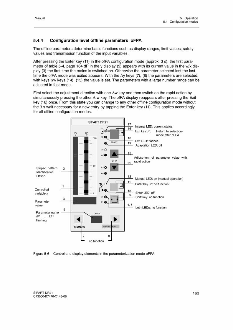
5 Operation5.4 Configuration modes
Manual
SIPART DR21C73000-B7476-C143-08
163
5.4.4 Configuration level offline parameters oFPA
The offline parameters determine basic functions such as display ranges, limit values, safetyvalues and transmission function of the input variables.
After pressing the Enter key (11) in the ofPA configuration mode (approx. 3 s), the first para-meter of table 5-4, page 164 dP in the y display (9) appears with its current value in the w/x dis-play (3) the first time the mains is switched on. Otherwise the parameter selected last the lasttime the ofPA mode was exited appears. With the Δy keys (7), (8) the parameters are selected,with keys Δw keys (14), (15) the value is set. The parameters with a large number range can beadjusted in fast mode.
First select the adjustment direction with one Δw key and then switch on the rapid action bysimultaneously pressing the other Δ w key. The ofPA display reappears after pressing the Exitkey (16) once. From this state you can change to any other offline configuration mode withoutthe 3 s wait necessary for a new entry by tapping the Enter key (11). This applies accordinglyfor all offline configuration modes.
SIPART DR21
SIPART DR21SIEMENS
SP-W
OUT-Y
C
PVX
A1
A2
A3
A4
ADAPT
100
50
0
W
X
SPW
no function
3
1
2
7 8
9
14
15
4, 5
6
19
11
12
13
1617
18
Adjustment of parameter value withrapid action
Controlledvariable x
Adaptation LED: off
Shift key: no function
Parameter namedP . . . L11flashing
Parametervalue
Exit key↗: Return to selection-mode after oFPA
Exit LED: flashes
Internal LED: current status
Manual LED: on (manual operation)
Enter key↗: no function
Enter LED: off
Striped patternIdentificationOffline
both LEDs: no function
Figure 5-6 Control and display elements in the parameterization mode oFPA
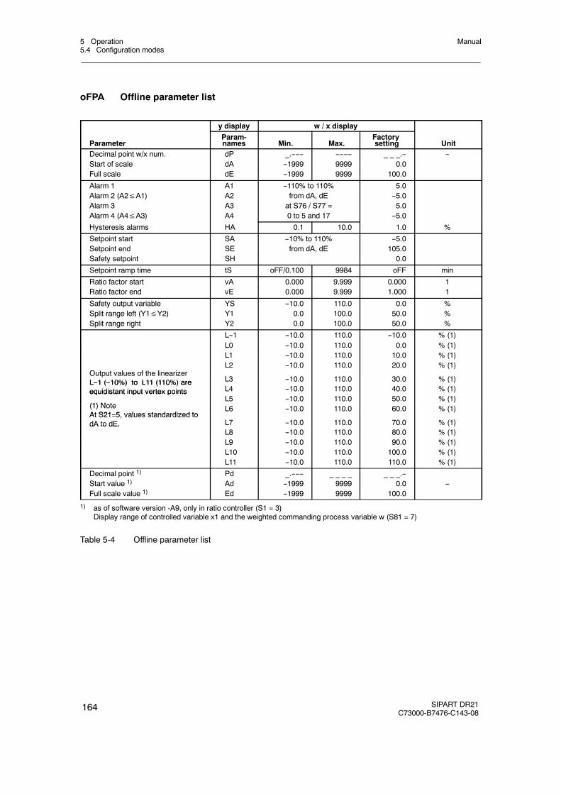
5 Operation5.4 Configuration modes
Manual
164 SIPART DR21C73000-B7476-C143-08
oFPA Offline parameter list
y display w / x display
ParameterParam-names Min. Max.
Factorysetting Unit
Decimal point w/x num. dP _.------ -------- _ _ _.-- --Start of scale dA --1999 9999 0.0Full scale dE --1999 9999 100.0
Alarm 1 A1 --110% to 110% 5.0Alarm 2 (A2≤A1) A2 from dA, dE --5.0Alarm 3 A3 at S76 / S77 = 5.0Alarm 4 (A4≤A3) A4 0 to 5 and 17 --5.0
Hysteresis alarms HA 0.1 10.0 1.0 %
Setpoint start SA --10% to 110% --5.0Setpoint end SE from dA, dE 105.0Safety setpoint SH 0.0
Setpoint ramp time tS oFF/0.100 9984 oFF min
Ratio factor start vA 0.000 9.999 0.000 1Ratio factor end vE 0.000 9.999 1.000 1
Safety output variable YS --10.0 110.0 0.0 %Split range left (Y1≤Y2) Y1 0.0 100.0 50.0 %Split range right Y2 0.0 100.0 50.0 %
L--1 --10.0 110.0 --10.0 % (1)L0 --10.0 110.0 0.0 % (1)L1 --10.0 110.0 10.0 % (1)
O t t l f th li iL2 --10.0 110.0 20.0 % (1)
Output values of the linearizerL--1 (--10%) to L11 (110%) are L3 --10.0 110.0 30.0 % (1)L--1 (--10%) to L11 (110%) areequidistant input vertex points L4 --10.0 110.0 40.0 % (1)equidistant input vertex points
(1) NoteL5 --10.0 110.0 50.0 % (1)
(1) NoteAt S21 5 values standardized to
L6 --10.0 110.0 60.0 % (1)At S21=5, values standardized todA to dE. L7 --10.0 110.0 70.0 % (1)dA to dE.
L8 --10.0 110.0 80.0 % (1)L9 --10.0 110.0 90.0 % (1)L10 --10.0 110.0 100.0 % (1)L11 --10.0 110.0 110.0 % (1)
Decimal point 1) Pd _.------ _ _ _ _ _ _ _.--Start value 1) Ad --1999 9999 0.0 --Full scale value 1) Ed --1999 9999 100.0
1) as of software version -A9, only in ratio controller (S1 = 3)Display range of controlled variable x1 and the weighted commanding process variable w (S81 = 7)
Table 5-4 Offline parameter list
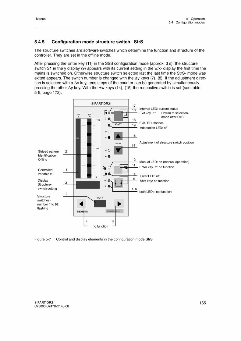
5 Operation5.4 Configuration modes
Manual
SIPART DR21C73000-B7476-C143-08
165
5.4.5 Configuration mode structure switch StrS
The structure switches are software switches which determine the function and structure of thecontroller. They are set in the offline mode.
After pressing the Enter key (11) in the StrS configuration mode (approx. 3 s), the structureswitch S1 in the y display (9) appears with its current setting in the w/x- display the first time themains is switched on. Otherwise structure switch selected last the last time the StrS- mode wasexited appears. The switch number is changed with the Δy keys (7), (8). If the adjustment direc-tion is selected with a Δy key, tens steps of the counter can be generated by simultaneouslypressing the other Δy key. With the Δw keys (14), (15) the respective switch is set (see table5-5, page 172).
SIPART DR21
SIPART DR21SIEMENS
SP-W
OUT-Y
C
PVX
A1
A2
A3
A4
ADAPT
100
50
0
W
X
SPW
no function
3
1
2
7 8
9
14
15
4, 5
6
19
11
12
13
1617
18
Adjustment of structure switch position
Controlledvariable x
Adaptation LED: off
Shift key: no function
Exit LED: flashes
Internal LED: current status
Manual LED: on (manual operation)
Enter key↗: no function
Enter LED: off
Striped patternIdentificationOffline
both LEDs: no function
DisplayStructure-switch setting
Structureswitches-number 1 to 92flashing
Exit key↗: Return to selection-mode after StrS
Figure 5-7 Control and display elements in the configuration mode StrS
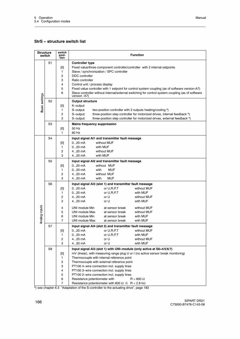
5 Operation5.4 Configuration modes
Manual
166 SIPART DR21C73000-B7476-C143-08
StrS -- structure switch list
Structureswitch
switchposi-tion
Function
S1 Controller type[0] Fixed value/three-component controller/controller with 2 internal setpoints1 Slave / synchronization / SPC controller2 DDC controller3 Ratio controller4 Control unit / process display5 Fixed value controller with 1 setpoint for control system coupling (as of software version-A7)
ngs 6 Slave controller without internal/external switching for control system coupling (as of software
version -A7)
settin
S2 Output structure
sics
[0] K--output
Basi
1 S--output two-position controller with 2 outputs heating/cooling *)B
2 S--output: three-position step controller for motorized drives, internal feedback *)3 S--output: three-position step controller for motorized drives, external feedback *)
S3 Mains frequency suppression[0] 50 Hz1 60 Hz
S4 Input signal AI1 and transmitter fault message[0] 0...20 mA without MUF1 0...20 mA with MUF2 4...20 mA without MUF3 4...20 mA with MUF
S5 Input signal AI2 and transmitter fault message[0] 0...20 mA without MUF1 0...20 mA with MUF2 4...20 mA without MUF3 4...20 mA with MUF
S6 Input signal AI3 (slot 1) and transmitter fault message[0] 0...20 mA or U,R,P,T without MUF1 0...20 mA or U,R,P,T with MUF2 4...20 mA or U without MUF3 4...20 mA or U with MUF
puts 4 UNI module Min at sensor break without MUF
ginpu
5 UNI module Max at sensor break without MUF
alog 6 UNI module Min at sensor break with MUF
Analo
7 UNI module Max at sensor break with MUF
A
S7 Input signal AI4 (slot 2) and transmitter fault message[0] 0...20 mA or U,R,P,T without MUF1 0...20 mA or U,R,P,T with MUF2 4...20 mA or U without MUF3 4...20 mA or U with MUF
S8 Input signal AI3 (slot 1) with UNI--module (only active at S6=4/5/6/7)[0] mV (linear), with measuring range plug U or I (no active sensor break monitoring)1 Thermocouple with internal reference point2 Thermocouple with external reference point3 PT100 4--wire connection incl. supply lines4 PT100 3--wire connection incl. supply lines5 PT100 2--wire connection incl. supply lines6 Resistance potentiometer with R < 600 7 Resistance potentiometer with 600 ≤ R < 2.8 k
*) see chapter 6.3 “Adaptation of the S-controller to the actuating drive”, page 183

5 Operation5.4 Configuration modes
Manual
SIPART DR21C73000-B7476-C143-08
167
Structureswitch
switchposi-tion
Function
S9 Thermocouple type AI3 (slot 1) with UNI--module (only active at S8=1/2)
[0] Type L1 Type J2 Type K3 Type S4 Type B5 Type R6 Type E7 Type N8 Type T9 Type U10 any type (without linearization)
s
S10 Temperature unit AI3 (slot 1) with UNI--module (only active at S8=1/2/3/4/5)
puts [0] Degrees Celsius
inpu 1 Degrees Fahrenheit
login
2 Kelvin
Analo
S11S12S13S14
Root extraction AI1 to AI4no yes
AI1 [0] 1AI2 [0] 1AI3 [0] 1AI4 [0] 1
S15S16S17
S18S19S20
Assignment of x1, x2, x3, yN, yR, z from AI1A to AI4A0 % AI1A AI2A AI3A AI4A
x1 0 [1] 2 3 4x2 0 1 [2] 3 4x3/we 0 1 2 [3] 4
yN 0 1 2 3 [4]yR [0] 1 2 3 4z [0] 1 2 3 4
S21 Assignment of the linearizer (see ofPA) open[0] none
uts 1 AI1
inpu 2 AI2
alog
in
3 AI3
Ana 4 AI4A
5 x1
S22 Assignment slot 3[0] not used
3
1 4 DO / 2 DI (DO3 -- DO6 / DI3, DI4)4 DO / 1 DI (DO3 -- DO6 / DI3, DI4=0)
Slot3 2 5 DI (DI3 -- DI7)
Sl
3 2 relays (DO3, DO4)
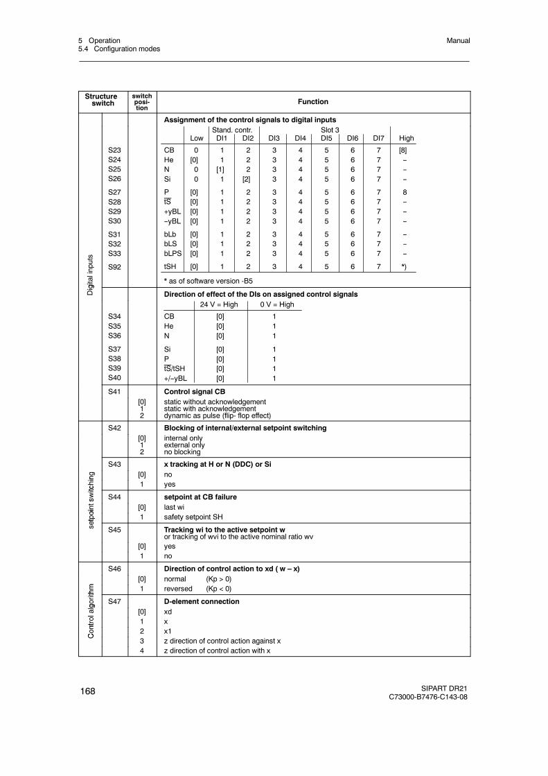
5 Operation5.4 Configuration modes
Manual
168 SIPART DR21C73000-B7476-C143-08
Structureswitch
switchposi-tion
Function
Assignment of the control signals to digital inputs
gitalinputs
S23S24S25S26
S27S28S29S30
S31S32S33
S92
Stand. contr. Slot 3Low DI1 DI2 DI3 DI4 DI5 DI6 DI7 High
CB 0 1 2 3 4 5 6 7 [8]He [0] 1 2 3 4 5 6 7 --N 0 [1] 2 3 4 5 6 7 --Si 0 1 [2] 3 4 5 6 7 --
P [0] 1 2 3 4 5 6 7 8tS [0] 1 2 3 4 5 6 7 --+yBL [0] 1 2 3 4 5 6 7 ----yBL [0] 1 2 3 4 5 6 7 --
bLb [0] 1 2 3 4 5 6 7 --bLS [0] 1 2 3 4 5 6 7 --bLPS [0] 1 2 3 4 5 6 7 --
tSH [0] 1 2 3 4 5 6 7 *)
* as of software version -B5
Digi
Direction of effect of the DIs on assigned control signals
S34S35S36
S37S38S39S40
24 V = High 0 V = High
CB [0] 1He [0] 1N [0] 1
Si [0] 1P [0] 1tS/tSH [0] 1+/--yBL [0] 1
S41 Control signal CB[0]12
static without acknowledgementstatic with acknowledgementdynamic as pulse (flip- flop effect)
S42 Blocking of internal/external setpoint switching[0]12
internal onlyexternal onlyno blocking
S43 x tracking at H or N (DDC) or Si
ing [0] no
tchin
1 yes
switc
S44 setpoint at CB failure
oints
[0] last wi
etpoi
1 safety setpoint SH
set
S45 Tracking wi to the active setpoint wor tracking of wvi to the active nominal ratio wv
[0] yes1 no
S46 Direction of control action to xd ( w – x)
m
[0] normal (Kp > 0)
thm 1 reversed (Kp < 0)
gorith
S47 D-element connection
olalg
[0] xd
ntrol
1 x
Cont
2 x1
C
3 z direction of control action against x4 z direction of control action with x
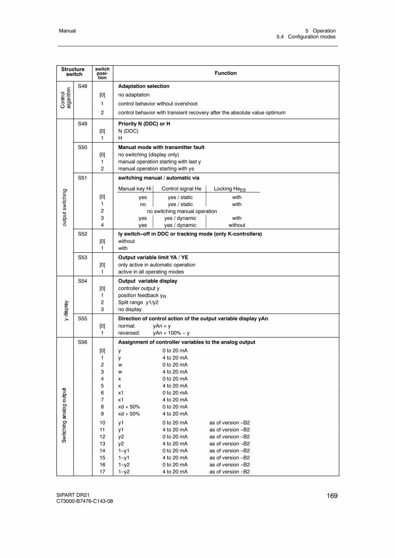
5 Operation5.4 Configuration modes
Manual
SIPART DR21C73000-B7476-C143-08
169
Structureswitch
switchposi-tion
Functionhm
S48 Adaptation selection
ntrol
orithm
[0] no adaptation
Cont
algo 1 control behavior without overshootC a
2 control behavior with transient recovery after the absolute value optimum
S49 Priority N (DDC) or H[0] N (DDC)1 H
S50 Manual mode with transmitter fault[0] no switching (display only)1 manual operation starting with last y2 manual operation starting with ys
S51 switching manual / automatic via
outputsw
itching
[0]1234
Manual key Hi Control signal He Locking HeESyes yes / static withno yes / static with
no switching manual operationyes yes / dynamic withyes yes / dynamic without
S52 Iy switch--off in DDC or tracking mode (only K-controllers)[0] without1 with
S53 Output variable limit YA / YE[0] only active in automatic operation1 active in all operating modes
S54 Output variable display[0] controller output y1 position feedback yR
lay 2 Split range y1/y2
ispla
3 no display
ydis
S55 Direction of control action of the output variable display yAn[0] normal: yAn = y1 reversed: yAn = 100% -- y
S56 Assignment of controller variables to the analog output
[0] y 0 to 20 mA1 y 4 to 20 mA2 w 0 to 20 mA3 w 4 to 20 mA4 x 0 to 20 mA
ut
5 x 4 to 20 mA
tput 6 x1 0 to 20 mA
outp
7 x1 4 to 20 mA
alog
o
8 xd + 50% 0 to 20 mA
analo
9 xd + 50% 4 to 20 mA
ingan
10 y1 0 to 20 mA as of version --B2
tchin
11 y1 4 to 20 mA as of version --B2
Switc 12 y2 0 to 20 mA as of version --B2
Sw
13 y2 4 to 20 mA as of version --B214 1--y1 0 to 20 mA as of version --B215 1--y1 4 to 20 mA as of version --B216 1--y2 0 to 20 mA as of version --B217 1--y2 4 to 20 mA as of version --B2
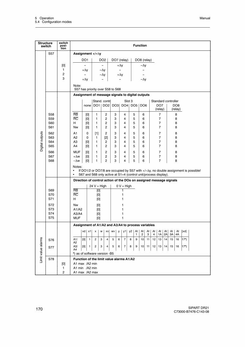
5 Operation5.4 Configuration modes
Manual
170 SIPART DR21C73000-B7476-C143-08
Structureswitch
switchposi-tion
Function
S57 Assignment +/--y
[0]123
DO1 DO2 DO7 (relay) DO8 (relay)
-- -- +Δy --Δy+Δy --Δy -- ---- --Δy +Δy --
+Δy -- -- --Δy
Note:S57 has priority over S58 to S68
Assignment of message signals to digital outputs
Digitaloutputs
S58S59S60S61
S62S63S64S65
S66S67S68
Stand. contr. Slot 3 Standard controllernone DO1 DO2 DO3 DO4 DO5 DO6 DO7 DO8
(relay) (relay)
RB [0] 1 2 3 4 5 6 7 8RC [0] 1 2 3 4 5 6 7 8H [0] 1 2 3 4 5 6 7 8Nw [0] 1 2 3 4 5 6 7 8
A1 0 [1] 2 3 4 5 6 7 8A2 0 1 [2] 3 4 5 6 7 8A3 [0] 1 2 3 4 5 6 7 8A4 [0] 1 2 3 4 5 6 7 8
MUF [0] 1 2 3 4 5 6 7 8+Δw [0] 1 2 3 4 5 6 7 8--Δw [0] 1 2 3 4 5 6 7 8
Notes: If DO1/2 or DO7/8 are occupied by S57 with +/--y, no double assignment is possible! S67 and S68 only active at S1=4 (control unit/process display).
Direction of control action of the DOs on assigned message signals
S69S70S71
S72S73S74S75
24 V = High 0 V = HighRB [0] 1RC [0] 1H [0] 1
Nw [0] 1A1/A2 [0] 1A3/A4 [0] 1MUF [0] 1
Assignment of A1/A2 and A3/A4 to process variables
valuealarms
S76
S77
xd x1 x w xv wv y y1 y2 AI AI AI AI AI AI AI AI |xd|1 2 3 4 1A 2A 3A 4A
A1/ [0] 1 2 3 4 5 6 7 8 9 10 11 12 13 14 15 16 17*)A2A3/ [0] 1 2 3 4 5 6 7 8 9 10 11 12 13 14 15 16 17*)A4*) as of software version -B5
Limitv
S78 Function of the limit value alarms A1/A2
Li [0] A1 max /A2 min1 A1 min /A2 min2 A1 max /A2 max
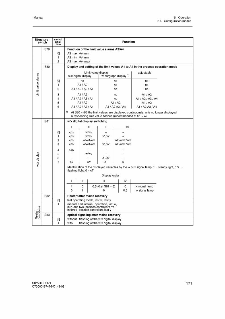
5 Operation5.4 Configuration modes
Manual
SIPART DR21C73000-B7476-C143-08
171
Structureswitch
switchposi-tion
Function
S79 Function of the limit value alarms A3/A4[0] A3 max /A4 min1 A3 min /A4 min2 A3 max /A4 max
S80 Display and setting of the limit values A1 to A4 in the process operation mode
Limitvaluealarms
[0]12
3456
Limit value display adjustablew/x-digital display w bargraph display 1)
no no noA1 / A2 no no
A1 / A2 / A3 / A4 no no
A1 / A2 no A1 / A2A1 / A2 / A3 / A4 no A1 / A2 / A3 / A4
A1 / A2 A1 / A2 A1 / A2A1 / A2 / A3 / A4 A1 / A2 A3 / A4 A1 / A2 A3 / A4
1) At S80 = 5/6 the limit values are displayed continuously, w is no longer displayed,a responding limit value flashes (recommended at S1 = 4).
S81 w/x digital display switching
w/xdisplay
[0]123
4567
I II III IV
x/xv w/wv -- --x/xv w/wv x1/xv --x/xv w/wi1/wv wE/wvE/wi2x/xv w/wi1/wv x1/xv wE/wvE/wi2
x/xv -- -- ---- w/wv -- ---- -- x1/xv --xv wv x1 w
Identification of the displayed variables by the w or x signal lamp: 1 = steady light, 0.5 =flashing light, 0 = off
Display order
I II III IV
1 0 0.5 (0 at S81 = 6) 0 x signal lamp0 1 0 0,5 w signal lamp
S82 Restart after mains recovery[0] last operating mode, last w, last y
art tions
1 manual and internal operation, last w,in K-and two--position controllers Ys,in three--position controllers last y
Restar
onditi
S83 optical signaling after mains recovery
Re
co [0] without flashing of the w/x digital display1 with flashing of the w/x digital display
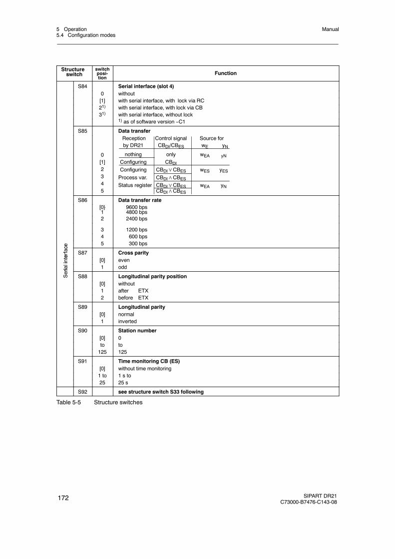
5 Operation5.4 Configuration modes
Manual
172 SIPART DR21C73000-B7476-C143-08
Structureswitch
switchposi-tion
Function
S84 Serial interface (slot 4)0 without[1] with serial interface, with lock via RC21) with serial interface, with lock via CB31) with serial interface, without lock
1) as of software version --C1
S85 Data transfer
0[1]2345
Reception Control signal Source forby DR21 CBDI/CBES wE yN
nothing only wEA yN
Configuring CBDIConfiguring CBDI∨CBES wES yESProcess var. CBDI∧CBESStatus register CBDI∨CBES wEA yN
CBDI∧CBESS86 Data transfer rate
[0}1
9600 bps4800 bps
2 2400 bps
3 1200 bps4 600 bps
ce
5 300 bps
erface
S87 Cross parity
inte [0] even
riali 1 odd
Seri
S88 Longitudinal parity position[0] without1 after ETX2 before ETX
S89 Longitudinal parity[0] normal1 inverted
S90 Station number[0] 0to to125 125
S91 Time monitoring CB (ES)[0] without time monitoring1 to 1 s to25 25 s
S92 see structure switch S33 following
Table 5-5 Structure switches
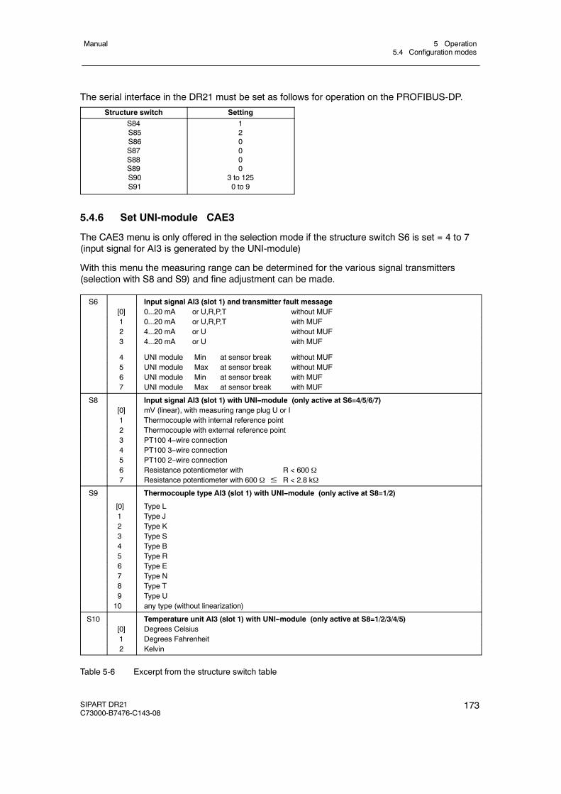
5 Operation5.4 Configuration modes
Manual
SIPART DR21C73000-B7476-C143-08
173
The serial interface in the DR21 must be set as follows for operation on the PROFIBUS-DP.
Structure switch SettingS84S85S86S87S88S89S90S91
120000
3 to 1250 to 9
5.4.6 Set UNI-module CAE3
The CAE3 menu is only offered in the selection mode if the structure switch S6 is set = 4 to 7(input signal for AI3 is generated by the UNI-module)
With this menu the measuring range can be determined for the various signal transmitters(selection with S8 and S9) and fine adjustment can be made.
S6 Input signal AI3 (slot 1) and transmitter fault message[0] 0...20 mA or U,R,P,T without MUF1 0...20 mA or U,R,P,T with MUF2 4...20 mA or U without MUF3 4...20 mA or U with MUF
4 UNI module Min at sensor break without MUF5 UNI module Max at sensor break without MUF6 UNI module Min at sensor break with MUF7 UNI module Max at sensor break with MUF
S8 Input signal AI3 (slot 1) with UNI--module (only active at S6=4/5/6/7)[0] mV (linear), with measuring range plug U or I1 Thermocouple with internal reference point2 Thermocouple with external reference point3 PT100 4--wire connection4 PT100 3--wire connection5 PT100 2--wire connection6 Resistance potentiometer with R < 600 7 Resistance potentiometer with 600 ≤ R < 2.8 k
S9 Thermocouple type AI3 (slot 1) with UNI--module (only active at S8=1/2)
[0] Type L1 Type J2 Type K3 Type S4 Type B5 Type R6 Type E7 Type N8 Type T9 Type U10 any type (without linearization)
S10 Temperature unit AI3 (slot 1) with UNI--module (only active at S8=1/2/3/4/5)[0] Degrees Celsius1 Degrees Fahrenheit2 Kelvin
Table 5-6 Excerpt from the structure switch table
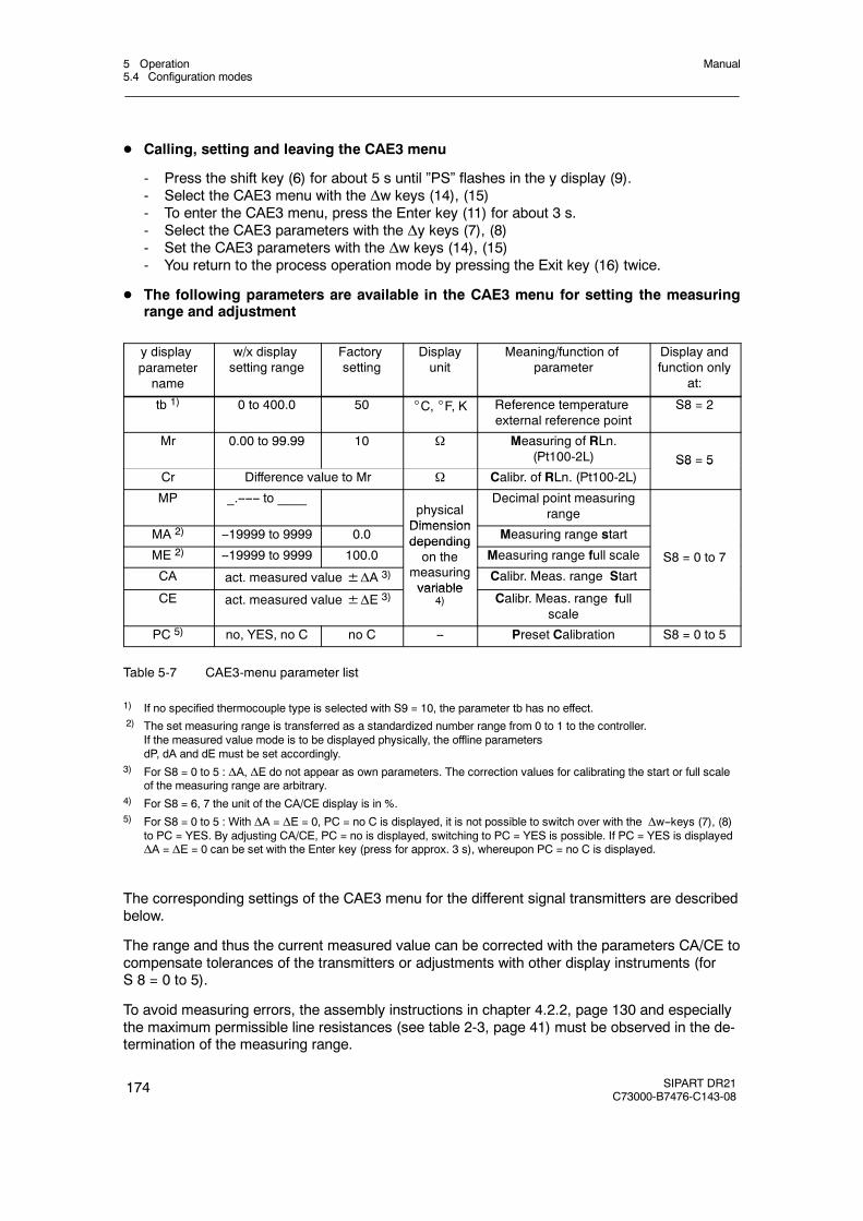
5 Operation5.4 Configuration modes
Manual
174 SIPART DR21C73000-B7476-C143-08
D Calling, setting and leaving the CAE3 menu
- Press the shift key (6) for about 5 s until ”PS” flashes in the y display (9).- Select the CAE3 menu with the Δw keys (14), (15)- To enter the CAE3 menu, press the Enter key (11) for about 3 s.- Select the CAE3 parameters with the Δy keys (7), (8)- Set the CAE3 parameters with the Δw keys (14), (15)- You return to the process operation mode by pressing the Exit key (16) twice.
D The following parameters are available in the CAE3 menu for setting the measuringrange and adjustment
y displayparametername
w/x displaysetting range
Factorysetting
Displayunit
Meaning/function ofparameter
Display andfunction only
at:
tb 1) 0 to 400.0 50 _C, _F, K Reference temperatureexternal reference point
S8 = 2
Mr 0.00 to 99.99 10 Ω Measuring of RLn.(Pt100-2L) S8 = 5
Cr Difference value to Mr Ω Calibr. of RLn. (Pt100-2L)S8 5
MP _.------ to ____physicalDimension
Decimal point measuringrange
MA 2) --19999 to 9999 0.0Dimensiondepending Measuring range start
ME 2) --19999 to 9999 100.0dependingon the Measuring range full scale S8 = 0 to 7
CA act. measured value±ΔA 3) measuringvariable
Calibr. Meas. range Start
CE act. measured value±ΔE 3)variable
4) Calibr. Meas. range fullscale
PC 5) no, YES, no C no C -- Preset Calibration S8 = 0 to 5
Table 5-7 CAE3-menu parameter list
1) If no specified thermocouple type is selected with S9 = 10, the parameter tb has no effect.2) The set measuring range is transferred as a standardized number range from 0 to 1 to the controller.
If the measured value mode is to be displayed physically, the offline parametersdP, dA and dE must be set accordingly.
3) For S8 = 0 to 5 : ΔA, ΔE do not appear as own parameters. The correction values for calibrating the start or full scaleof the measuring range are arbitrary.
4) For S8 = 6, 7 the unit of the CA/CE display is in %.5) For S8 = 0 to 5 : With ΔA = ΔE = 0, PC = no C is displayed, it is not possible to switch over with the Δw--keys (7), (8)
to PC = YES. By adjusting CA/CE, PC = no is displayed, switching to PC = YES is possible. If PC = YES is displayedΔA = ΔE = 0 can be set with the Enter key (press for approx. 3 s), whereupon PC = no C is displayed.
The corresponding settings of the CAE3 menu for the different signal transmitters are describedbelow.
The range and thus the current measured value can be corrected with the parameters CA/CE tocompensate tolerances of the transmitters or adjustments with other display instruments (forS 8 = 0 to 5).
To avoid measuring errors, the assembly instructions in chapter 4.2.2, page 130 and especiallythe maximum permissible line resistances (see table 2-3, page 41) must be observed in the de-termination of the measuring range.
5 Operation5.4 Configuration modes
Manual
SIPART DR21C73000-B7476-C143-08
175
5.4.6.1 Measuring range for mV (S8 = 0)
D MA/ME – set measuring range
Call parameters MA, ME, set range start and full scale:Measuring range limits -175 mV ≤MA≤ME ≤+175 mV
D CA/CE – fine adjustment (only if necessary)
Call parameter CA,Set signal to start of scaleCorrect the display with CA if necessary
Call parameter CE,Set signal to full scale,Correct the display with CE if necessary
5.4.6.2 Measuring range for U, I (S8 = 0)only with measuring range plug 6DR2805-8J
D MA/ME – set measuring range
Call parameters MA, ME, set range start and full scale:Measuring range limits -175 mV ≤MA≤ME ≤+175 mV
Initialization in the measuring range plug
0 to 10V or 0 to 20mA signal corresponds to MA = 0mV ME = 100mV2 to 10V or 4 to 20mA signal corresponds to MA = 20mV ME = 100mV
D CA/CE – fine adjustment (only if necessary)
Call parameter CA,Set signal to start of scaleCorrect the display with CA if necessary
Call parameter CE,Set signal to full scale,Correct the display with CE if necessary
5.4.6.3 Measuring range for thermocouple with internal reference point (S8 = 1)
D MA/ME – set measuring range
Call parameters MA, ME, set the start of scale and full scale according to the thermocoupletype (S9) and the temperature unit (S10).
5 Operation5.4 Configuration modes
Manual
176 SIPART DR21C73000-B7476-C143-08
D CA/CE – fine adjustment (only if necessary)
Call parameter CA,Set signal to start of scaleCorrect the display with CA if necessary
Call parameter CE,Set signal to full scale,Correct the display with CE if necessary
5.4.6.4 Measuring range for thermocouple with external reference point (S8 = 2)
D tb – external reference points-temperature
Set the external reference point temperature with tb. Specify temperature unit with S10.Attention: tb has no effect at S9 = 10!
D MA/ME – set measuring range
Call parameters MA, ME, set the start of scale and full scale according to the thermocoupletype (S9) and the temperature unit.
D CA/CE – fine adjustment (only if necessary)
Call parameter CA,Set signal to start of scaleCorrect the display with CA if necessary
Call parameter CE,Set signal to full scale,Correct the display with CE if necessary
5.4.6.5 Measuring range for PT100 four-wire and three-wire connection(S8 = 3,4)
D MA/ME – set measuring range
Call parameters MA, ME, set range start and full scale:Measuring range limits -200 _C ≤MA≤ME≤+850 _C
Specify temperature unit with S10.
D CA/CE – fine adjustment (only if necessary)
Call parameter CA,Set signal to start of scaleCorrect the display with CA if necessary
Call parameter CE,Set signal to full scale,Correct the display with CE if necessary
5 Operation5.4 Configuration modes
Manual
SIPART DR21C73000-B7476-C143-08
177
5.4.6.6 Measuring range for PT100 two-wire connection (S8 = 5)
D MR/CR adjustment of the feed line resistance
Path 1: The feed line resistance is known.
- Enter the known resistance with parameter MR.--- CR is ignored.
Path 2: The feed line resistance is not known.
- Short circuit PT100-sensor at the measuring point.- Call parameter CR and press the Enter key (11) until 0.00 Ω
is displayed.- MR displays the measured resistance value
D MA/ME – set measuring range
Call parameters MA, ME, set range start and full scale:Measuring range limits -200 _C ≤MA≤ME≤+850 _C
Specify temperature unit with S10.
D CA/CE – fine adjustment (only if necessary)
Call parameter CA,Set signal to start of scaleCorrect the display with CA if necessary
Call parameter CE,Set signal to full scale,Correct the display with CE if necessary
5.4.6.7 Measuring range for resistance potentiometer (S8 = 6, 7)
Path 1 : The start and end values of the R- potentiometer are known.
- Call parameter MA, ME, set start of scale and full scale:0 Ω≤MA≤ME≤600 Ω / 2.8 kΩ
- Parameters CA/CE display at R=MA 0%, at R=ME 100 %.The following applies for a 3-wire connection: R = Rp+ RL4The following applies for a 4-wire connection: R = Rp+ RL1 + RL4
Path 2 : The start and end values of the R- potentiometer are not known.
- Call parameter CA ,Move output to position 0 %, press the Enter key (11) until 0.0 %is displayed.
- Call parameter CE,Move output to position 100 %, press the Enter key until 100.0 %is displayed.
- Parameters MA/ME show the appropriate resistance values.- MP must be set so that there is no ’exceeding of the range’ (display (3):
oFL)

5 Operation5.4 Configuration modes
Manual
178 SIPART DR21C73000-B7476-C143-08
5.4.7 APSt (All Preset) Reset to factory setting
APSt serves to reset all controller functions (parameters and structures) to the factory setting.We recommend you to run the APSt function first if major changes are to be made to the con-figuration. The controller is in offline operation in the structuring mode.
NOTICE
The APSt function cannot be canceled.
SIPART DR21
SIPART DR21SIEMENS
SP-W
OUT-Y
C
PVX
A1
A2
A3
A4
ADAPT
100
50
0
W
X
SPW
no function
3
1
2
7 8
9
14
15
4, 5
6
19
11
12
13
1617
18
Adjustment no or YES, set YES
Striped patternID offline
Controlledvariable x
Adaptation LED: off
Shift key: no function
Exit key↗: Return to selection modeafter APSt
Exit LED: flashes
Internal LED: current status
Manual LED: ON (manual operation)
Enter key↗: until configuration modeStrS appears
both LEDs: no function
Enter LED: flashes if YES
Displayno or YES
PS(Parameteriza-tion/structuring)
Figure 5-8 Control and display elements in the structuring mode APSt
No appears after jumping to the structuring mode APSt with the Enter key (11). Set YES with+Δw key (14, 15) and press the Enter key (11) until the configuration mode StrS appears. ThePreset function is run. Select structuring mode Strs by pressing the Enter key and re-structurethe controller.
The offline and online parameters must also be reset.
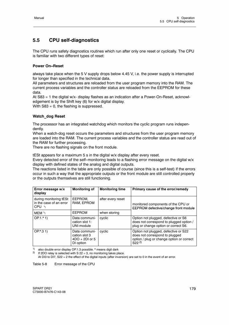
5 Operation5.5 CPU self-diagnostics
Manual
SIPART DR21C73000-B7476-C143-08
179
5.5 CPU self-diagnostics
The CPU runs safety diagnostics routines which run after only one reset or cyclically. The CPUis familiar with two different types of reset:
Power On--Reset
always take place when the 5 V supply drops below 4.45 V, i.e. the power supply is interruptedfor longer than specified in the technical data.All parameters and structures are reloaded from the user program memory into the RAM. Thecurrent process variables and the controller status are reloaded from the EEPROM for thesedata.At S83 = 1 the digital w/x- display flashes as an indication after a Power-On-Reset, acknowl-edgement is by the Shift key (6) for w/x digital display.With S83 = 0, the flashing is suppressed.
Watch_dog Reset
The processor has an integrated watchdog which monitors the cyclic program runs indepen-dently.When a watch-dog reset occurs the parameters and structures from the user program memoryare loaded into the RAM. The current process variables and the controller status are read out ofthe RAM for further processing.There are no flashing signals on the front module.
tESt appears for a maximum 5 s in the digital w/x display after every reset.Every detected error of the self--monitoring leads to a flashing error message on the digital w/xdisplay with defined states of the analog and digital outputs.The reactions listed in the table are only possible of course (since this is a self-test) if the errorsoccur in such a way that the appropriate outputs or the front module are still controlled properlyor the outputs themselves are still functioning.
Error message w/xdisplay
Monitoring of Monitoring time Primary cause of the error/remedy
during monitoring tEStin the case of an errorCPU
EEPROM,RAM, EPROM
after every reset
monitored components of the CPU orEEPROM defective/change front module
MEM EEPROM when storingEEPROM defective/change front module
OP.1.* 1) Data communi-cation slot 1:UNI-module
cyclic Option not plugged, defective or S6does not correspond to plugged option /plug or change option or correct S6.
OP.*.3 1) Data communi-cation slot 34DO + 2DI or 5DI option
cyclic Option not plugged, defective or S22does not correspond to pluggedoption / plug or change option or correctS22 2)
1) also double error display OP.1.3 possible. * means digit dark2) If 2DO relay is selected with S 22 = 3, no monitoring takes place.
At DI3 to DI7, S22 = 2 the effect of the digital inputs (after inversion) are set to 0 in the event of an error.
Table 5-8 Error message of the CPU

5 Operation5.5 CPU self-diagnostics
Manual
180 SIPART DR21C73000-B7476-C143-08
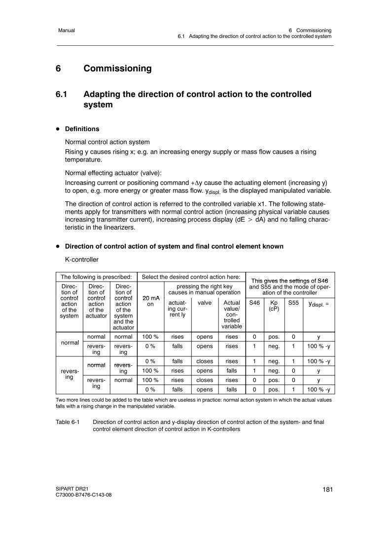
6 Commissioning6.1 Adapting the direction of control action to the controlled system
Manual
SIPART DR21C73000-B7476-C143-08
181
6 Commissioning
6.1 Adapting the direction of control action to the controlledsystem
D Definitions
Normal control action systemRising y causes rising x; e.g. an increasing energy supply or mass flow causes a risingtemperature.
Normal effecting actuator (valve):Increasing current or positioning command +y cause the actuating element (increasing y)to open, e.g. more energy or greater mass flow. ydispl. is the displayed manipulated variable.
The direction of control action is referred to the controlled variable x1. The following state-ments apply for transmitters with normal control action (increasing physical variable causesincreasing transmitter current), increasing process display (dE> dA) and no falling charac-teristic in the linearizers.
D Direction of control action of system and final control element known
K-controller
The following is prescribed: Select the desired control action here:This gives the settings of S46
Direc-tion ofcontrol
Direc-tion ofcontrol
Direc-tion ofcontrol 20 mA
pressing the right keycauses in manual operation
This gives the settings of S46and S55 and the mode of oper-
ation of the controllercontrolactionof thesystem
controlactionof theactuator
controlactionof thesystemand theactuator
20 mAon actuat-
ing cur-rent ly
valve Actualvalue/con-trolledvariable
S46 Kp(cP)
S55 ydispl. =
lnormal normal 100 % rises opens rises 0 pos. 0 y
normal revers-ing
revers-ing
0 % falls opens rises 1 neg. 1 100 % -y
normal revers-0 % falls closes rises 1 neg. 1 100 % -y
revers-i
normal revers-ing 100 % rises opens falls 1 neg. 0 yrevers
ing revers-i
normal 100 % rises closes rises 0 pos. 0 ying 0 % falls opens falls 0 pos. 1 100 % -y
Two more lines could be added to the table which are useless in practice: normal action system in which the actual valuesfalls with a rising change in the manipulated variable.
Table 6-1 Direction of control action and y-display direction of control action of the system- and finalcontrol element direction of control action in K-controllers
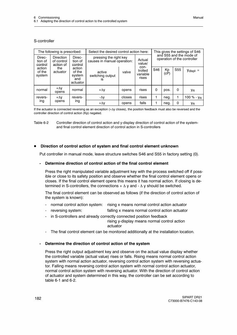
6 Commissioning6.1 Adapting the direction of control action to the controlled system
Manual
182 SIPART DR21C73000-B7476-C143-08
S-controller
The following is prescribed: Select the desired control action here: This gives the settings of S46d S55 d th d fDirec-
tion ofcontrol
Directionof controlaction of
Direc-tion ofcontrol
pressing the right keycauses in manual operation: Actual
value/con
g gand S55 and the mode ofoperation of the controller
controlactionof thesystem
action ofthe
actuator
controlactionof thesystemand
actuator
activeswitching output
is
valvecon-trolledvariablerises
S46 Kp(cP)
S55 ydispl. =
normal +yopens normal +y opens rises 0 pos. 0 yR
revers-i
+y revers-i
-y closes rises 1 neg. 1 100 % - yRing
yopens ing +y opens falls 1 neg. 0 yR
If the actuator is connected reversing as an exception (+y closes), the position feedback must also be reversed and thecontroller direction of control action (Kp) negated.
Table 6-2 Controller direction of control action and y-display direction of control action of the system-and final control element direction of control action in S-controllers
D Direction of control action of system and final control element unknown
Put controller in manual mode, leave structure switches S46 and S55 in factory setting (0).
- Determine direction of control action of the final control element
Press the right manipulated variable adjustment key with the process switched off if poss-ible or close to its safety position and observe whether the final control element opens orcloses. If the final control element opens this means it has normal action. If closing is de-termined in S-controllers, the connections + y and - y should be switched.
The final control element can be observed as follows (if the direction of control action ofthe system is known):
- normal control action system: rising x means normal control action actuator- reversing system: falling x means normal control action actuator- in S-controllers and already correctly connected position feedback
rising y-display means normal control actionactuator
- The final control element can be monitored additionally at the installation location.
- Determine the direction of control action of the system
Press the right output adjustment key and observe on the actual value display whetherthe controlled variable (actual value) rises or falls. Rising means normal control actionsystem with normal action actuator, reversing control action system with reversing actua-tor. Falling means reversing control action system with normal control action actuator,normal control action system with reversing actuator. With the direction of control actionof actuator and system determined in this way, the controller can be set according totable 6-1 and 6-2.
6 Commissioning6.2 Setting of actuating time in K-controllers (S2 = 0)
Manual
SIPART DR21C73000-B7476-C143-08
183
6.2 Setting of actuating time in K-controllers (S2 = 0)
D Actuating time tP, tM
Set the actuating time tP (open) or tM (closed) to the actuating time of the following actuator. Ifthe control circuit is to be settled additionally, e.g. to avoid hard impact on the actuating drive,tP, tM can be further increased in Automatic operation.
The value of tP is usually set identical to the value of tM.
6.3 Adaptation of the S-controller to the actuating drive
D Output Two-position controller for heating/cooling (S2 = 1)
The setting range y can be divided into two sections. The offline-parameters Y1 and Y2 andthe online-parameters YA and YE determine tehse sections(see fig. 3-24, page 98.)
The period duration and the shortest turn-on- and turn-off duration are determined in thecooling branch (section [YA, Y1]) by the online-parameters tM and tA and in the heatingbranch (section [Y2, YE]) by the online parameters tP and tE.
The period durations tP and tM should be chosen as great as possible, whereby the follow-ing should be observed:
- Great values of tP and tM result in low wear of the internal and external switchgear.
- Large values cause a periodic fluctuation of the controlled variable x which is greater thefaster the controlled system is.
D S-controller with internal feedback (S2 = 2)
Set the actuating time of the actuating drive (e.g. 60 s) with the online-parameters tP, tM (0.1to 1000 s).
NOTICE
The factory setting is 1 s!
The online-parameter tE (minimum turn-on duration) should be selected at least greatenough that the actuating drive starts moving reliably under consideration of the powerswitches connected before it. The greater the value of tE, the more resistant to wear andmore gently the switching and drive elements connected after the controller operate. Largevalues of tE require a greater dead band AH in which the controller cannot control definedbecause the resolution of the controlled variable diminishes with increasing turn-on duration.
The factory setting for tE is 200 ms. This corresponds to a y-resolution in a 60-s-actuatingdrive of:
100 % · tEtP (or tM)
=Δy = 100 % · 200 ms60 s
= 0.33 %
6 Commissioning6.3 Adaptation of the S-controller to the actuating drive
Manual
184 SIPART DR21C73000-B7476-C143-08
The minimum possible resolution is transferred with the system gain Ks to the controlledvariable
Δx = Ks · Δy
The parameter tA (minimum turn-off duration) should be chosen at least great enough thatthe actuating drive is safely disconnected under consideration of the power switches con-nected before it before a new pulse appears (especially in the opposite direction). Thegreater the value of tA, the more resistant to wear the switching- and drive elements con-nected after the controller operate and the greater the dead time of the controller undersome circumstances. The value of tA is usually set identical to the value of tE.
tA = tE = 120 to 240 ms are recommended for 60 s actuating drives. The more restless thecontrolled system, the greater the two parameters should be selected if this is reasonablyjustified by the controller result.
The response threshold AH must be set corresponding to the set tE and the resulting Δ y orΔx. The following condition must be satisfied:
AH > Δx2 or AH >
Ks⋅tE⋅100 %2⋅tP (or tM)
Otherwise the controller outputs positioning increments although the control deviation hasreached the smallest possible value due to the finite resolution. For setting AH, see chapter5.4, page 154.
D S-controller with external feedback (S2 = 3)
The position control circuit is optimized with the online-parameters tP/tM. The same relation-ships apply as in the S-controller with internal position feedback whereby the dynamic of theposition control circuit (non-linearities, follow-up) is added to the criteria of the processabilityof the positioning increments by the final control element. It will usually be necessary to se-lect tP/tM and the resulting response threshold smaller than in the S-controller with internalposition feedback for the above mentioned reasons.
The position control circuit is optimized in manual mode. To do this, S54 is set to 0 for theoptimizing phase so that the manual manipulated variable is preset as an absolute value. Itmust be noted that the active manipulated variable trails the manipulated variable displaydue to the actuating time of the actuator.
In the case of non-linearity in the position control circuit, the optimization must take place inthe range of greatest slope.
Procedure for optimization of the position control circuit:
- Set S54 to 0 (position controller also active in manual mode)
- Set tA and tE so that the actuating drive can just process the positioning increments (seeS-controller with internal feedback).
- Set 1st order filter of the y R -input (t1, 2, 3 or 4) to 0.01 TP/TM (real actuating time of thedrive).
- Increase tP/tM until the position control circuit overshoots due to small manual changesin the manipulated variable (observe opposite pulse on the Δ y-LEDs (10) in the y-dis-play).
6 Commissioning6.4 Setting the filter and the response threshold
Manual
SIPART DR21C73000-B7476-C143-08
185
- Reduce tP/tM slightly again until the position control circuit settles.
- Reset S54 to 1 (position controller no longer active in manual mode)
6.4 Setting the filter and the response threshold
Set the structure switch S3 to the mains frequency 50 or 60 Hz existing in the system (factorysetting 50 Hz) to suppress faults due to the mains frequency.
D Filter of first order of analog inputs
The filter time constants (t1 to t4) for the input filters are set in the onPA-parameterizationmode and to the greatest possible value permitted by the control circuit without affecting thecontrollability (t1 to t4 < Tg). When using the adaptation method the appropriate input filtersmust be optimized.
D Adaptive, non-linear filters of the control difference
Since the dead zone sets itself automatically and its size is therefore unknown, the time tF(onPA) can only be selected so great that the control circuit cannot oscillate in the case of alarge dead zone (tF less than Tg). When using the D-part (PD, PID) the use of the adaptive,non-linear filter is strongly recommended because the input noise amplified by Kp·vv can besuppressed.
If filters are required, they must be set before using the adaptation method.
D Optimization of the response threshold AH
If the output of the controller is to additionally settled or the load on the actuator reduced, thenecessary response threshold AH can be increased. The response threshold AH is given inthree-position controllers (S2 = 2, 3) by the setting of tE (see chapter 6.3, page 183) andmust automatically be greater than zero. In K-controllers and two-position controllers(S2 = 0, 1) a response threshold of approx. 0.5 % is recommendable.
It must be taken into account that the remaining control error can assume the value of theset response threshold.
6 Commissioning6.5 Automaticsettingof controlparameters by theadaptationmethod
Manual
186 SIPART DR21C73000-B7476-C143-08
6.5 Automatic setting of control parameters by the adaptationmethodsee chapter 3.9 “Adaptation (S48)”, page 113
The adaptation method should always be preferred to manual settings because the controlresults with the parameters gained from adaptation are better especially in slow controlledsystems and this saves optimization time.
D Presetting
- S48 selecting the control behavior (structuring mode StrS)
No adaptation is possible when S48 = 0. In position 1 a control behavior without over-shoot is offered. In position 2 changes in the command variables can be expected with amaximum 5 % overshoot.
- tU: Monitoring time (parameterization mode AdAP)
tU is only necessary for the error messages and has no influence on the quality ofidentification It can always be started with tU = oFF. Otherwise tU must be set at leasttwice as great as the transient time T 95 of the controlled system. After successfuladaptation tU is automatically set to 2T95. At tU < 0.1 h (6 min), tU = oFF is displayed.
- Pv: Direction of the step command (parameterization mode AdAP)
The direction of the controlled variable change from the set operating point is selectedwith this configuring switch: xmanual±Δx =± ks (ymanual±Δy). In controlled systemswith batches it is recommendable to perform one adaptation with rising x and one withfalling x. The averaged or dynamically more uncritical parameters can then be used forthe control.
- dy: Amplitude of the step command (parameterization mode AdAP)
The step command must be selected so great that the controlled variable changes by atleast 4 % and the controlled variable change must be 5 times the average noise level. Thegreater the controlled variable change, the better the identification quality. Controlled variablechanges of approx. 10 % are recommended.
D Notes on the adaptation results
- D-part
In S-controllers and K-controllers on 1st order controlled systems, the D part brings nonoticeable advantages due to the finite actuating time Ty or for reasons founded in thecontrol theory. The disadvantages in the form of wear on the positioning side dominate.
- Range limits
If one of the determined parameters reaches its range limits, the other parameter shouldbe adjusted slightly in the opposite direction of action.If 8th order systems are identified, the determined kp must be reduced for safetyreasons. The determined Kp must be increased again if the control circuit is too slow(uncritical).
6 Commissioning6.5 Automaticsettingof controlparameters by theadaptationmethod
Manual
SIPART DR21C73000-B7476-C143-08
187
- Kp variation
In the special cases 1st order controlled system in connection with PI and PID controllersand 2nd order controlled systems in connection with PID-controllers, the Kp can be va-ried freely. In controller design according to the absolute value optimum, Kp can be in-creased up to 30 % as a rule without the control behavior becoming critical.

6 Commissioning6.5 Automaticsettingof controlparameters by theadaptationmethod
Manual
188 SIPART DR21C73000-B7476-C143-08
Process
opera-
tion-level
bLb=0,bLPS=0
Shiftkey
pressforabout5s
Selection-
level
+-
onPA
AdAP
Configurationlevel
AdAP
Pre-adaptation↗
Pre-settings
AdaptationLE
D(19)off
(6)
Exit
(16)
Enter
(11) Exit
(16)
Δw-
keys
(14),(15)
Duringadaptation
AdaptationLE
D(19)flashing
Com
pleteprocessdisplay
Startof
adaptation
Enterkey(11)
1)xx
=manipulated
variable
oldpara--
meter-
values
are
retained
newparameter-
values
areprovided
fortransfer
Enter
(11)Error
message
acknow
ledge
Adaptation
repeat
Aborted
adaptation
AdaptationLE
D(19)off
byerrors
intheadap-
tation
methodsee
table5-3,
page
162
manually
by Exitkey
Errormessage
ExitA
dAPfor
errorcorrection
Switchcontroller
toautomatic
mode,new
parametersare
effective
Oldparameters
areoverwritten
bynewparame-
ters
Switchcontroller
tomanualm
ode,
setdesired
operatingpoint
andwaitfor
stationarycondi-
tion.
tU0FF,0.1to24
h
dPv
nEG,P
oSdY
0,5to90
%
xx1)
Strt
w cP tn tv AH
xx1)
Strt
Oldvalues
can
onlybe
setin
onPA
configu-
rationlevel
Postadaptation
AdaptationLE
D(19)on
vv cP tn tv AH
newparame-
tervalues
canbe
chan-
gedwith
Δw-keys
(14),(15)
Pi..x
Pid.x2)
Param
eterselect-
ablewithΔy-keys
(7),(8)
2)Param
eterset
selectablewith
Δw-keys(14),
(15)
Figure 6-1 Overview configuration level AdAP
6 Commissioning6.6 Manual setting of the control parameters
Manual
SIPART DR21C73000-B7476-C143-08
189
6.6 Manual setting of the control parameterswithout knowledge of the plant behavior
The control parameters for optimum control of the system are not yet known in this case. Tokeep the control circuit stable in all cases, the following factory settings must be made:
Proportional action factor Kp = 0.1Integral action time Tn = 9984 sDerivative action time Tv = oFF
D P-controller (control signal P = high)
- Set the desired setpoint and set the control difference to zero in manual operation.
- The operating point necessary for the control difference is set automatically in manualoperation at Yo=AUto (factory setting). The operating point can also be set manually bysetting the online-parameter yo to the desired operating point.
- Switch to automatic operation.
- Increase Kp slowly until the control loop tends to oscillate due to slight setpoint changes.
- Reduce Kp slightly until the oscillations disappear.
D PD-controller (control signal P = high)
- Set the desired setpoint and set the control difference to zero in manual operation.
- The operating point necessary for the control difference is set automatically in manualoperation at Yo = AUto (factory setting). The operating point can also be set manuallyby setting the online-parameter y o to the desired operating point.
- Switch to automatic operation.
- Increase Kp slowly until the control loop tends to oscillate due to slight setpoint changes.
- Switch Tv from oFF to 1 s.
- Increase Tv until the oscillations disappear.
- Increase Kp slowly until oscillations reappear.
- Repeat the setting according to the two previous steps until the oscillations can no longerbe eliminated.
- Reduce Tv and Kp slightly until the oscillations are eliminated.
6 Commissioning6.6 Manual setting of the control parameters
Manual
190 SIPART DR21C73000-B7476-C143-08
D PI-controller (control signal P = Low)
- Set the desired setpoint and set the control difference to zero in manual operation.
- Switch to automatic operation.
- Increase Kp slowly until the control loop tends to oscillate due to slight setpoint changes.
- Reduce Kp slightly until the oscillations disappear.
- Reduce Tn until the control loop tends to oscillate again.
- Increase Tn slightly until the tendency to oscillate disappears.
D PID-controller (control signal P = Low)
- Set the desired setpoint and set the control difference to zero in manual operation.
- Switch to automatic operation.
- Increase Kp slowly until the control loop tends to oscillate due to slight setpoint changes.
- Switch Tv from oFF to 1 s.
- Increase Tv until the oscillations disappear.
- Increase Kp slowly again until the oscillations reappear.
- Repeat the setting according to the previous two steps until the oscillations cannot beeliminated again.
- Reduce Tv and Kp slightly until the oscillations stop.
- Reduce Tn until the control loop tends to oscillate again.
- Increase Tn slightly until the tendency to oscillate disappears

6 Commissioning6.7 Manual setting of the control parameters
Manual
SIPART DR21C73000-B7476-C143-08
191
6.7 Manual setting of the control parametersafter the transient function
If the transient function of the controlled system is active or can be determined, the controlparameters can be set according to the setting guidelines specified in the literature. The transi-ent function can be recorded in the„ Manual operation” position of the controller by a suddenchange in the manipulated variable and the course of the controlled variable registered with arecorder. This will roughly give a transient function corresponding to the one shown infigure 6-2.
Good average values from the setting data of several authors give the following rules of thumb:
P-controller:
Proportional gain factor Kp≈ TgTu · Ks
PI-controller:
Proportional gain factor Kp≈ 0.8 · TgTu · Ks
Integral action time Tn≈ 3 · Tu
PID-controller:
Proportional gain factor Kp≈ 1.2 · TgTu · Ks
Integral action time Tn≈ Tu
Derivative action time Tv≈ 0.4 Tu
y manipulated variablex measured variablet timeTu delay timeTg compensation timeKs transmission factor of the controlled system
y
t
x
t
Tg
x Ks = xy
Tu
y
Figure 6-2 Transient function of a controlled system with compensation

6 Commissioning6.7 Manual setting of the control parameters
Manual
192 SIPART DR21C73000-B7476-C143-08
7 Application examples for configuring the controller7.1 General
Manual
SIPART DR21C73000-B7476-C143-08
193
7 Application examples for configuring the controller
7.1 General
Frequent applications/connections of the SIPART DR21 controllers in the form of configurationexamples are listed below. The circuits are sorted according to their application S-controller,K-controller, control unit/process display or two-position controller. All input and output connec-tions and the order numbers of the respective required controllers or accessory modules arestated. A principle circuit diagram of the control circuit and a short description make compre-hension easier
We have purposely described the simple applications in very great detail to help the technicianabove all who only needs to design these circuits very occasionally.
Mains voltage
As shown, the power supply must be fused and the PE conductor connected. The permissiblepower supply range must be stated respectively with the type number of the controller.Fuses and connecting leads are not supplied with the controllers.
Input circuits
A wide variety of input circuits are shown. Please note that the supply voltage remaining for thetransmitter may only be 15 V DC in the worst case when a two-wire transmitter is fed by theSIPART DR21 and the analog inputs AI1/AI2 are used at the same time.
Output circuits
The outputs are represented uniformly. In S-controllers, the switching outputs are output viarelays which may be loaded with a max. 250 V AC. If the position outputs of the S-controller aredesired with digital signals, the digital outputs DO1 and DO2 must be used.
If inductances (e.g. positioning motors, contactors, etc.) are switched with the plannedrelay outputs, an adequate interference suppression must be provided for on the systemside by wiring with RC-combinations or other suitable means in order to achieve EMCprotection aims.
7 Application examples for configuring the controller7.1 General
Manual
194 SIPART DR21C73000-B7476-C143-08
D Configuring
Structure switches S
All controllers are supplied with the specified factory settings and must be structured to suitthe application during commissioning.
The switch positions for the respective application which deviate from the factorysetting are listed in the examples.
In addition other settings may be necessary due to system-specific criteria.
The following configuration examples have exclusively parallel circuits. Therefore the struc-ture switches which relate to the serial interface are not specified.
Parameters onPA and oFPA
The controllers must be adapted in every case using the system data. The factory setting ofthe control parameters must be selected so that the control loop does not tend to oscillateeven under worst case conditions (Kp = 0, 1, Tn = 9984 s). Kp and Tn or y0 and if necess-ary Tv and AH must be set.
Control algorithm
All configuration examples (except Z1) are shown for PI or PID behavior. Switching to P orPD behavior is possible with a digital input signal (structure switch S27). In the SIPARTDR21 as an S-controller, a P-or PD-controller operation is only possible with external posi-tion feedback (S2=3).
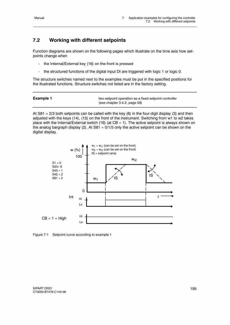
7 Application examples for configuring the controller7.2 Working with different setpoints
Manual
SIPART DR21C73000-B7476-C143-08
195
7.2 Working with different setpoints
Function diagrams are shown on the following pages which illustrate on the time axis how set-points change when
- the Internal/External key (16) on the front is pressed
- the structured functions of the digital input DI are triggered with logic 1 or logic 0.
The structure switches named next to the examples must be put in the specified positions forthe illustrated functions. Structure switches not listed are in the factory setting.
Example 1 two-setpoint operation as a fixed setpoint controller(see chapter 3.4.2, page 59)
At S81 = 2/3 both setpoints can be called with the key (6) in the four-digit display (3) and thenadjusted with the keys (14), (15) on the front of the instrument. Switching from w1 to w2 takesplace with the Internal/External switch (16) (at CB = 1). The active setpoint is always shown onthe analog bargraph display (2). At S81 = 0/1/5 only the active setpoint can be shown on thedigital display.
wi2
wi1
t0
w (%)
100
S1 = 0S23= 8S45 = 1S42 = 2S81 = 2
w1 = wi1 (can be set on the front)w2 = wi2 (can be set on the front)tS = setpoint ramp
Int
CB = 1 = HighLo
Hi
tStS
Lo
Hi
Figure 7-1 Setpoint curve according to example 1
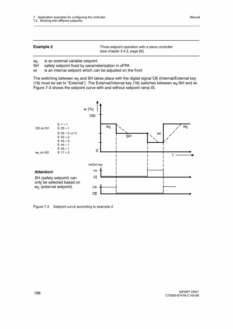
7 Application examples for configuring the controller7.2 Working with different setpoints
Manual
196 SIPART DR21C73000-B7476-C143-08
Example 2 Three-setpoint operation with a slave controller(see chapter 3.4.3, page 62)
wE is an external variable setpointSH safety setpoint fixed by parameterization in oFPAwi is an internal setpoint which can be adjusted on the front
The switching between wE and SH takes place with the digital signal CB (Internal/External key(16) must be set to ”External”). The External/Internal key (16) switches between wE/SH and wi.Figure 7-2 shows the setpoint curve with and without setpoint ramp tS.
SHwi
t0
w (%)
100
Int
wES 1 = 1
CB on DI1 S 23 = 1
S 25 = 0 (¸1)S 42 = 2S 43 = 0S 44 = 1S 45 = 1
wE on AI2 S 17 = 2
Int/Ext key
Int
CB
CB
wE
Attention!SH (safety setpoint) canonly be selected based onwE (external setpoint).
Figure 7-2 Setpoint curve according to example 2

7 Application examples for configuring the controller7.2 Working with different setpoints
Manual
SIPART DR21C73000-B7476-C143-08
197
Example 3 Four-setpoint operation with one slave controller with Internal/External switching and CB signal through the digital input
The analog input AI2/wE is overcontrolled to 0 or 100%:
wi setpoint which can be adjusted on the frontwE setpoint limit fixed by parameterization oFPA (setpoint limit start SA), wE over
controlled to 0 %.SH safety setpoint set by parameterization.wE setpoint limit fixed by parameterization oFPA (setpoint limit end SE)
wE overcontrolled to 100 %.
Switchings take place:
wi= key (16) to InternalwE= key (16) to External (INT), CB signal High (CB). AI2 overcontrolled to 0% (SA)SH= key (16) to External, CB from High to Low (CB)wE= key (16) to External (INT), CB signal High (CB). AI2 overcontrolled to 100% (SE)
Restriction of this circuit wi and SH must be within the limits SA to SE.
Also only the active setpoint can be displayed at S81 = 2/3. SH can only be reached by thetransition INT∧CB to INT∧CB.
wi
wE (SA)
SH
wE (SE)
t0
w (%)
100
S1 = 1wE on AI2 S17 = 2CB on DI1 S23 = 1
S42 = 2S43 = 0S44 = 1S45 = 1
Int/Ext key
100 %
DI1
AI2
Int
Int
CB
CB
0 %
Attention!SH (safety setpoint) can onlybe selected based on wE (ex-ternal setpoint).
Figure 7-3 Setpoint curve according to example 3
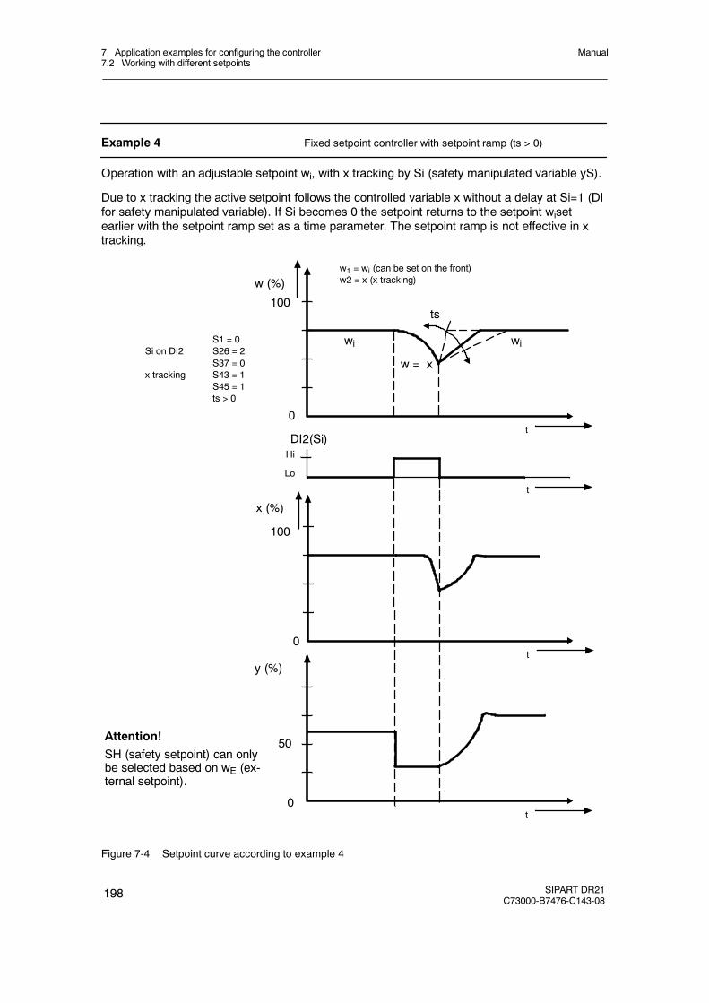
7 Application examples for configuring the controller7.2 Working with different setpoints
Manual
198 SIPART DR21C73000-B7476-C143-08
Example 4 Fixed setpoint controller with setpoint ramp (ts > 0)
Operation with an adjustable setpoint wi, with x tracking by Si (safety manipulated variable yS).
Due to x tracking the active setpoint follows the controlled variable x without a delay at Si=1 (DIfor safety manipulated variable). If Si becomes 0 the setpoint returns to the setpoint wisetearlier with the setpoint ramp set as a time parameter. The setpoint ramp is not effective in xtracking.
wiwi
w = x
t0
w (%)
100
S1 = 0Si on DI2 S26 = 2
S37 = 0x tracking S43 = 1
S45 = 1ts > 0
w1 = wi (can be set on the front)w2 = x (x tracking)
ts
t
Lo
DI2(Si)Hi
t0
x (%)
100
t0
y (%)
50Attention!SH (safety setpoint) can onlybe selected based on wE (ex-ternal setpoint).
Figure 7-4 Setpoint curve according to example 4
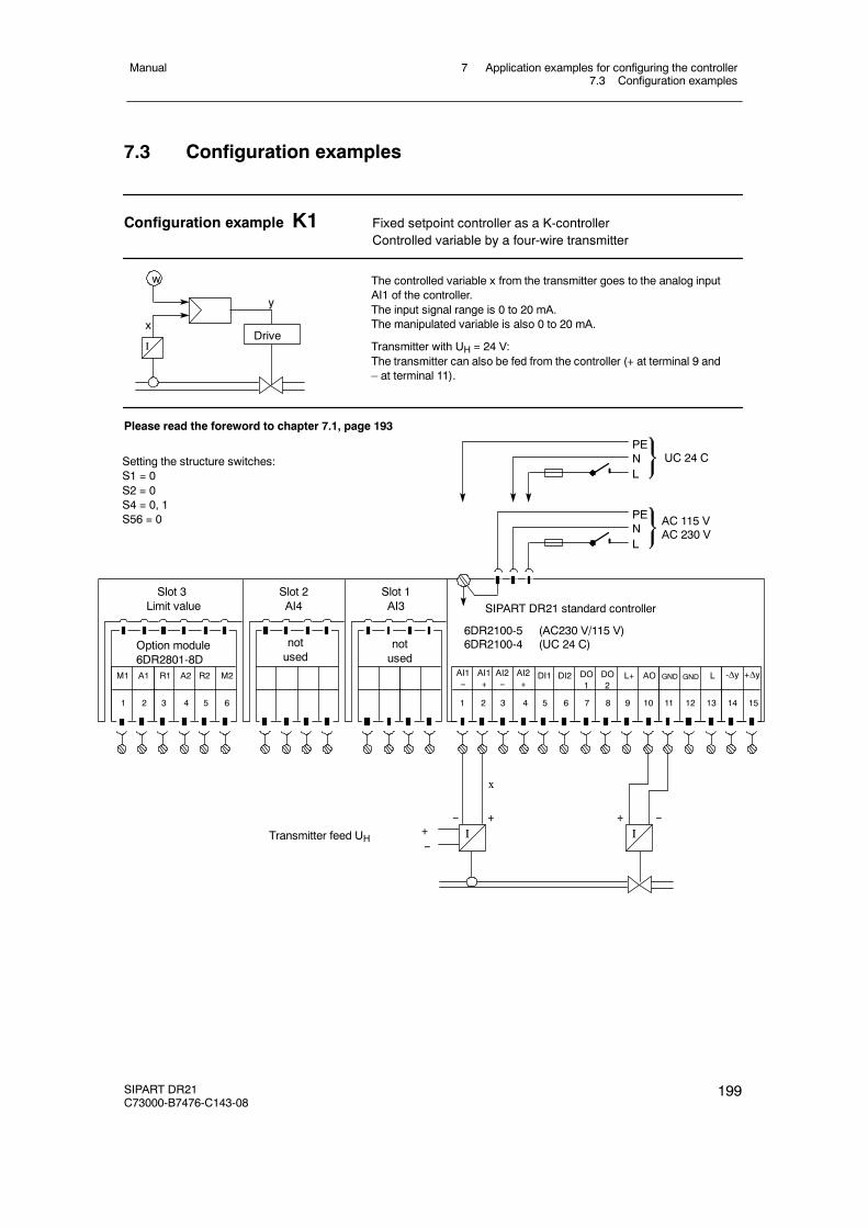
7 Application examples for configuring the controller7.3 Configuration examples
Manual
SIPART DR21C73000-B7476-C143-08
199
7.3 Configuration examples
Configuration example K1 Fixed setpoint controller as a K-controllerControlled variable by a four-wire transmitter
x
w
I
y
Drive
The controlled variable x from the transmitter goes to the analog inputAI1 of the controller.The input signal range is 0 to 20 mA.The manipulated variable is also 0 to 20 mA.
Transmitter with UH = 24 V:The transmitter can also be fed from the controller (+ at terminal 9 and– at terminal 11).
Please read the foreword to chapter 7.1, page 193
AI1--
PENL
SIPART DR21 standard controller
PENL
UC 24 C
AC 115 VAC 230 V
6DR2100-5 (AC230 V/115 V)6DR2100-4 (UC 24 C)
AI1+
AI2--
AI2+
DI1 DI2 DO1
DO2
GNDL+ AO
1 2 3 4 5 6 7 8 9 10 11 12
Setting the structure switches:S1 = 0S2 = 0S4 = 0, 1S56 = 0
Slot 1AI3
notused
Slot 2AI4
notused
Slot 3Limit value
Option module6DR2801-8D
M1 A1 R2 M2R1 A2
1 2 3 4 5 6
Transmitter feed UH
--I
+
x
--I
++--
-ΔyL
13 14 15
+ΔyGND
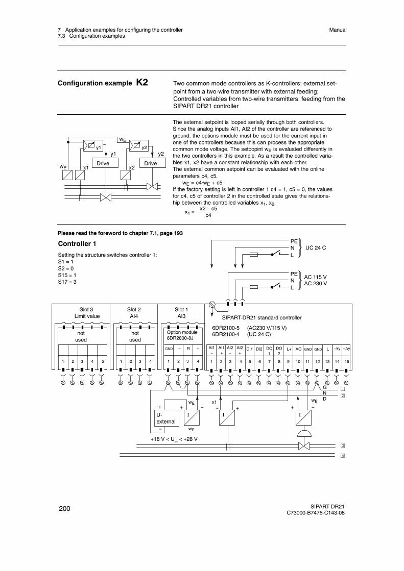
7 Application examples for configuring the controller7.3 Configuration examples
Manual
200 SIPART DR21C73000-B7476-C143-08
Configuration example K2 Two common mode controllers as K-controllers; external set-point from a two-wire transmitter with external feeding;Controlled variables from two-wire transmitters, feeding from theSIPART DR21 controller
x1
y2
Drive
The external setpoint is looped serially through both controllers.Since the analog inputs AI1, AI2 of the controller are referenced toground, the options module must be used for the current input inone of the controllers because this can process the appropriatecommon mode voltage. The setpopint wE is evaluated differently inthe two controllers in this example. As a result the controlled varia-bles x1, x2 have a constant relationship with each other.The external common setpoint can be evaluated with the onlineparameters c4, c5.
wE = c4·wE + c5If the factory setting is left in controller 1 c4 = 1, c5 = 0, the valuesfor c4, c5 of controller 2 in the controlled state gives the relations-hip between the controlled variables x1, x2.
x1 =x2 -- c5c4
wEDrive
x2
y1 y2
wE
y1
Please read the foreword to chapter 7.1, page 193
Controller 1
Setting the structure switches controller 1:S1 = 1S2 = 0S15 = 1S17 = 3
Slot 1AI3
Slot 2AI4
notused
Slot 3Limit value
Option module6DR2800-8J
--I
wE
-- R +
1 2 3 4
GND
+
--
+
U-external
wE
I-- +
x1
I--+wE
+18 V < U_ < +28 V
notused
AI1--
PENL
SIPART-DR21 standard controller
PENL
UC 24 C
AC 115 VAC 230 V
6DR2100-5 (AC230 V/115 V)6DR2100-4 (UC 24 C)
AI1+
AI2--
AI2+
DI1 DI2 DO1
DO2
L+ AO
1 2 3 4 5 6 7 8 9 10 11 12
-ΔyL
13 14 15
+Δy
1 2 3 4 1 2 3 45
¡
©
¢
£
GND GND GND
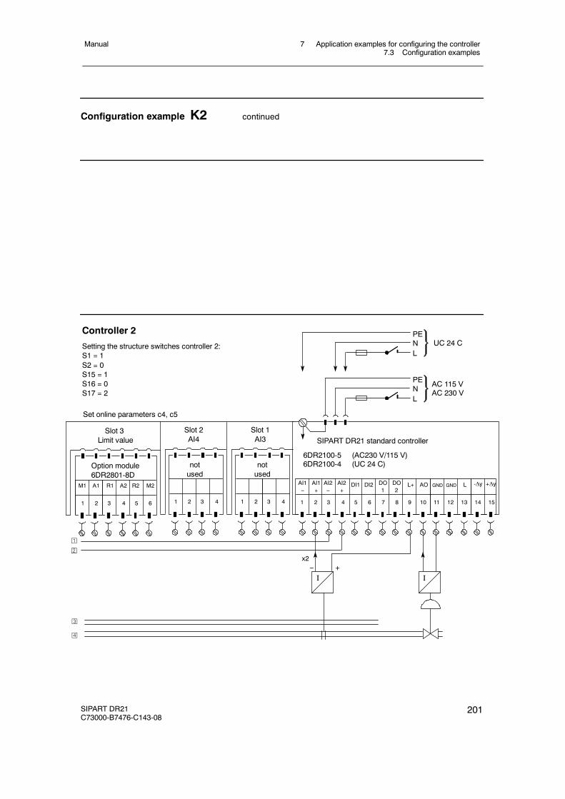
7 Application examples for configuring the controller7.3 Configuration examples
Manual
SIPART DR21C73000-B7476-C143-08
201
Configuration example K2 continued
Controller 2
Setting the structure switches controller 2:S1 = 1S2 = 0S15 = 1S16 = 0S17 = 2
Slot 1AI3
Slot 2AI4
notused
I-- +
x2
I
Slot 3Limit value
Option module6DR2801-8D
M1 A1 R2 M2R1 A2
1 2 3 4 5 6
notused
AI1--
PENL
SIPART DR21 standard controller
PENL
UC 24 C
AC 115 VAC 230 V
6DR2100-5 (AC230 V/115 V)6DR2100-4 (UC 24 C)
AI1+
AI2--
AI2+
DI1 DI2 DO1
DO2
L+ AO
1 2 3 4 5 6 7 8 9 10 11 12
-ΔyL
13 14 15
+Δy
1 2 3 4 1 2 3 4
¡
©
Set online parameters c4, c5
¢
£
GND GND
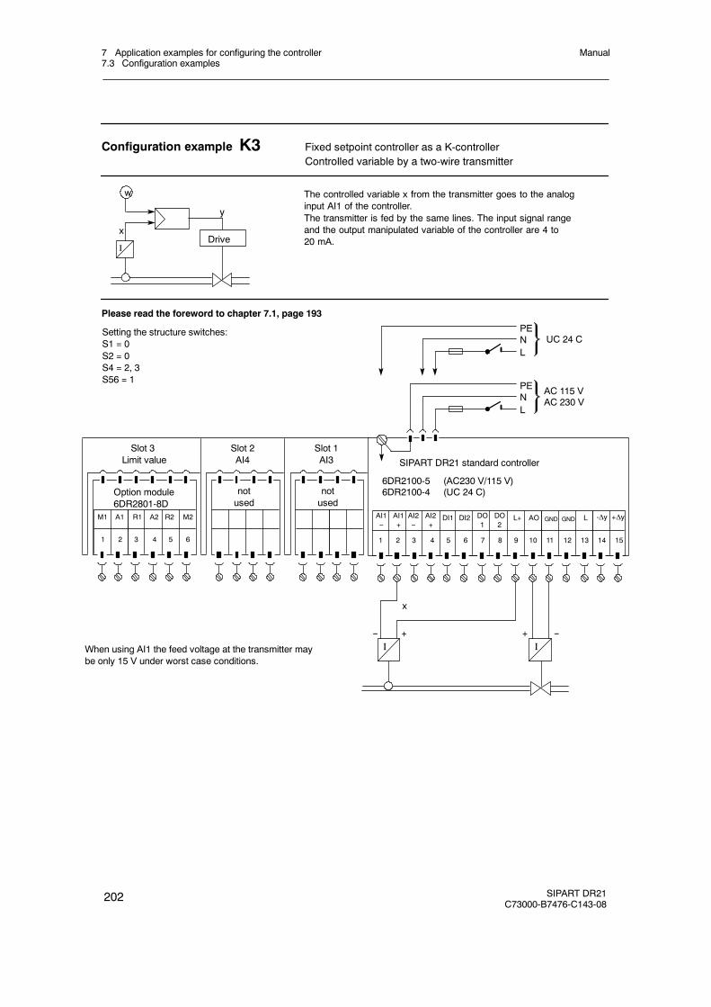
7 Application examples for configuring the controller7.3 Configuration examples
Manual
202 SIPART DR21C73000-B7476-C143-08
Configuration example K3 Fixed setpoint controller as a K-controllerControlled variable by a two-wire transmitter
x
w
I
y
Drive
The controlled variable x from the transmitter goes to the analoginput AI1 of the controller.The transmitter is fed by the same lines. The input signal rangeand the output manipulated variable of the controller are 4 to20 mA.
Please read the foreword to chapter 7.1, page 193
Setting the structure switches:S1 = 0S2 = 0S4 = 2, 3S56 = 1
Slot 1AI3
notused
Slot 2AI4
notused
Slot 3Limit value
Option module6DR2801-8D
M1 A1 R2 M2R1 A2
1 2 3 4 5 6
When using AI1 the feed voltage at the transmitter maybe only 15 V under worst case conditions.
--I
+
x
--I
+
AI1--
PENL
SIPART DR21 standard controller
PENL
UC 24 C
AC 115 VAC 230 V
6DR2100-5 (AC230 V/115 V)6DR2100-4 (UC 24 C)
AI1+
AI2--
AI2+
DI1 DI2 DO1
DO2
L+ AO
1 2 3 4 5 6 7 8 9 10 11 12
-ΔyL
13 14 15
+ΔyGND GND
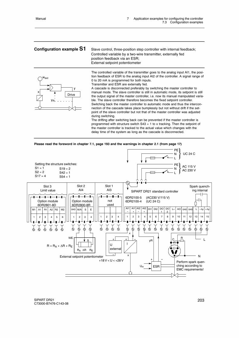
7 Application examples for configuring the controller7.3 Configuration examples
Manual
SIPART DR21C73000-B7476-C143-08
203
Configuration example S1 Slave control, three-position step controller with internal feedback;Controlled variable by a two-wire transmitter, externally fedposition feedback via an ESR;External setpoint potentiometer
The controlled variable of the transmitter goes to the analog input AI1, the posi-tion feedback of ESR to the analog input AI2 of the controller. A signal range of0 to 20 mA is programmed for both inputs.Transmitter and ESR are externally fed.A cascade is disconnected preferably by switching the master controller tomanual mode. The slave controller is still in automatic mode, its setpoint is stillthe output signal of the master controller, i.e. now its manual manipulated varia-ble. The slave controller therefore becomes the fixed setpoint controller.Switching back the master controller to automatic mode and thus the intercon-nection of the cascade takes place bumplessly but not without drift if the set-point of the slave controller but not that of the master controller was adjustedduring switching.The drifting after switching back can be prevented if the master controller isprogrammed with structure switch S43 = 1 to x tracking. Then the setpoint ofthe master controller is tracked to the actual value which changes with thedelay time of the system as long as the cascade is disconnected.
x
wext
y
Drive
yR
RA REΔR
S
AI1--
PENL
PENL
UC 24 C
AC 115 VAC 230 V
AI1+
AI2--
AI2+
DI1 DI2 DO1
DO2
L+ AO
1 2 3 4 5 6 7 8 9 10 11 12
Setting the structure switches:S1 = 1S2 = 2S17 = 4
Slot 1AI3
Slot 2AI4
Spark quench-ing internal
Slot 3Limit value
Option module6DR2801-8D
M1 A1 R2 M2R1 A2
1 2 3 4 5 6
notused
M/A S E
1 2 3 4
Option module6DR2800-8R
L +Δy
13 14 15
--Δy
S19 = 2S42 = 1S54 = 1
Please read the foreword in chapter 7.1, page 193 and the warnings in chapter 2.1 (from page 17)
SIPART DR21 standard controller
6DR2100-5 (AC230 V/115 V)6DR2100-4 (UC 24 C)
External setpoint potentiometer
R = RA + ΔR + RE
WE
Uexternal
I+ + --
-- x
x
ESRUH
+ --
yR LRC
N
Perform spark quen-ching according toEMC requirements!
+18V < U < +28V
1 2 3 4
GND GNDGND
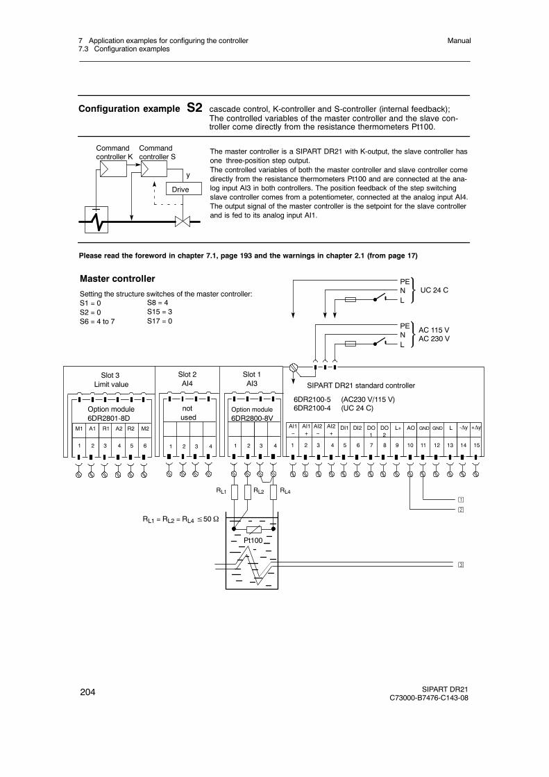
7 Application examples for configuring the controller7.3 Configuration examples
Manual
204 SIPART DR21C73000-B7476-C143-08
Configuration example S2 cascade control, K-controller and S-controller (internal feedback);The controlled variables of the master controller and the slave con-troller come directly from the resistance thermometers Pt100.
The master controller is a SIPART DR21 with K-output, the slave controller hasone three-position step output.The controlled variables of both the master controller and slave controller comedirectly from the resistance thermometers Pt100 and are connected at the ana-log input AI3 in both controllers. The position feedback of the step switchingslave controller comes from a potentiometer, connected at the analog input AI4.The output signal of the master controller is the setpoint for the slave controllerand is fed to its analog input AI1.
y
Drive
Commandcontroller K
Commandcontroller S
Master controller
Setting the structure switches of the master controller:S1 = 0S2 = 0S6 = 4 to 7
Slot 1AI3
Slot 2AI4
notused
Slot 3Limit value
Option module6DR2801-8D
M1 A1 R2 M2R1 A2
1 2 3 4 5 6
S8 = 4S15 = 3S17 = 0
Option module6DR2800-8V
1 2 3 4
Please read the foreword in chapter 7.1, page 193 and the warnings in chapter 2.1 (from page 17)
AI1--
PENL
SIPART DR21 standard controller
PENL
UC 24 C
AC 115 VAC 230 V
6DR2100-5 (AC230 V/115 V)6DR2100-4 (UC 24 C)
AI1+
AI2--
AI2+
DI1 DI2 DO1
DO2
L+ AO
1 2 3 4 5 6 7 8 9 10 11 12
-ΔyL
13 14 15
+Δy
Pt100
RL1 = RL2 = RL4≤50Ω
RL1 RL2 RL4
1 2 3 4
¡
©
¢
GND GND
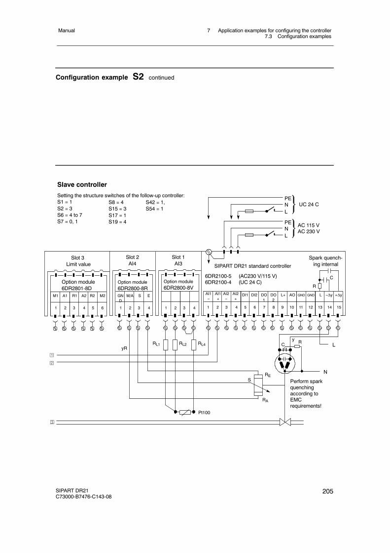
7 Application examples for configuring the controller7.3 Configuration examples
Manual
SIPART DR21C73000-B7476-C143-08
205
Configuration example S2 continued
AI1--
PENL
PENL
UC 24 C
AC 115 VAC 230 V
AI1+
AI2--
AI2+
DI1 DI2 DO1
DO2
L+ AO
1 2 3 4 5 6 7 8 9 10 11 12
Slave controller
Setting the structure switches of the follow-up controller:S1 = 1S2 = 3S6 = 4 to 7S7 = 0, 1
Slot 1AI3
Slot 2AI4
Spark quench-ing internal
Slot 3Limit value
Option module6DR2801-8D
M1 A1 R2 M2R1 A2
1 2 3 4 5 6
GND
M/A S E
1 2 3 4
Option module6DR2800-8R
L +Δy
13 14 15
--Δy
S8 = 4S15 = 3S17 = 1S19 = 4
SIPART DR21 standard controller
6DR2100-5 (AC230 V/115 V)6DR2100-4 (UC 24 C)
LRC
N
Perform sparkquenchingaccording toEMCrequirements!
S42 = 1,S54 = 1
y
RA
RES
Option module6DR2800-8V
1 2 3 4
RL1 RL2 RL4yR
Pt100
R
C
¡
©
¢
GND GND
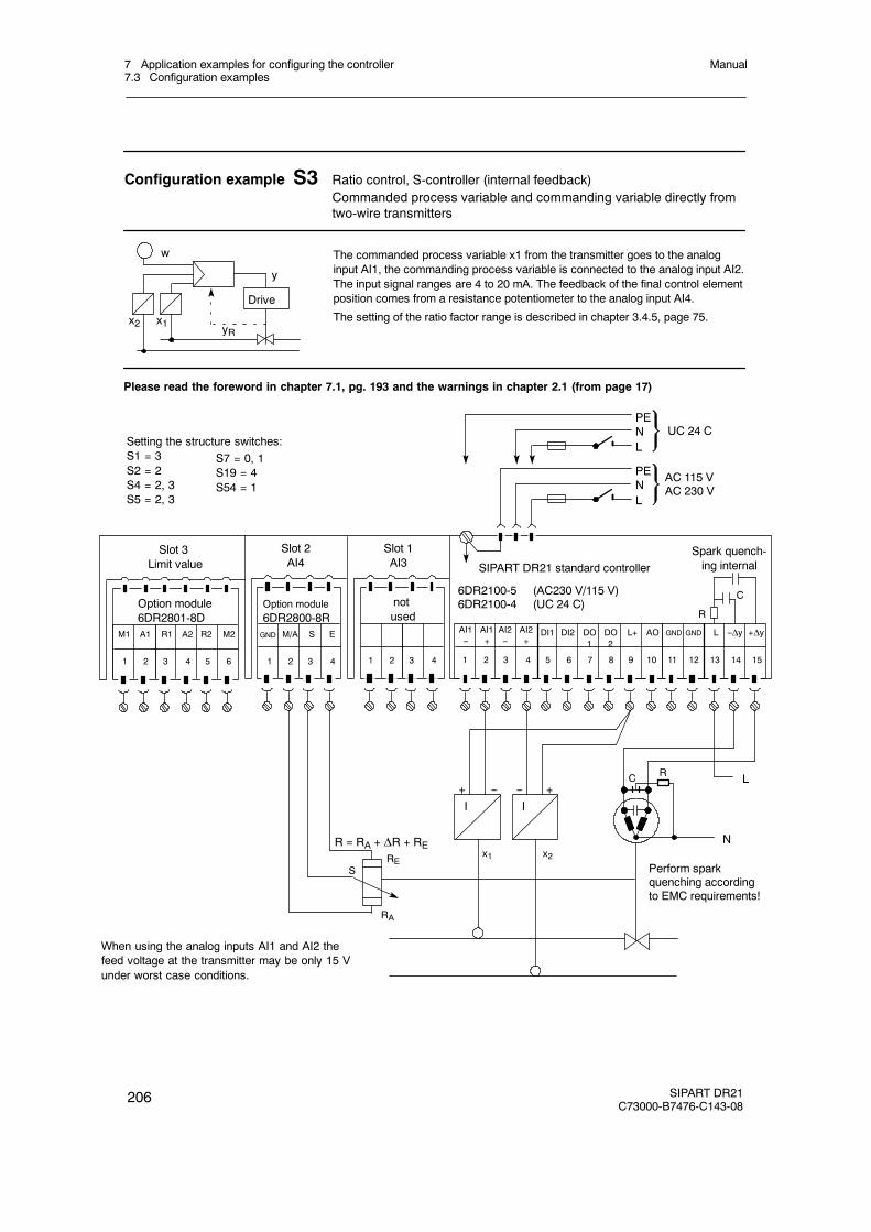
7 Application examples for configuring the controller7.3 Configuration examples
Manual
206 SIPART DR21C73000-B7476-C143-08
Configuration example S3 Ratio control, S-controller (internal feedback)Commanded process variable and commanding variable directly fromtwo-wire transmitters
The commanded process variable x1 from the transmitter goes to the analoginput AI1, the commanding process variable is connected to the analog input AI2.The input signal ranges are 4 to 20 mA. The feedback of the final control elementposition comes from a resistance potentiometer to the analog input AI4.
The setting of the ratio factor range is described in chapter 3.4.5, page 75.x2
w
y
Drive
yRx1
AI1--
PENL
PENL
UC 24 C
AC 115 VAC 230 V
AI1+
AI2--
AI2+
DI1 DI2 DO1
DO2
L+ AO
1 2 3 4 5 6 7 8 9 10 11 12
Setting the structure switches:S1 = 3S2 = 2S4 = 2, 3S5 = 2, 3
Slot 1AI3
Slot 2AI4
Spark quench-ing internal
Slot 3Limit value
Option module6DR2801-8D
M1 A1 R2 M2R1 A2
1 2 3 4 5 6
notused
M/A S E
1 2 3 4
Option module6DR2800-8R
L +Δy
13 14 15
--Δy
S7 = 0, 1S19 = 4S54 = 1
Please read the foreword in chapter 7.1, pg. 193 and the warnings in chapter 2.1 (from page 17)
SIPART DR21 standard controller
6DR2100-5 (AC230 V/115 V)6DR2100-4 (UC 24 C)
R = RA + ΔR + RE
LRC
N
Perform sparkquenching accordingto EMC requirements!
R
C
I+ --
RA
RES
I+--
x2x1
When using the analog inputs AI1 and AI2 thefeed voltage at the transmitter may be only 15 Vunder worst case conditions.
1 2 3 4
GND GND GND

7 Application examples for configuring the controller7.3 Configuration examples
Manual
SIPART DR21C73000-B7476-C143-08
207
Configuration example Z1 Fixed setpoint control with PD two-position controllerThe controlled variable comes from a thermocouple with internal refer-ence point.
The controlled variable of the thermocouple is fed directly to the analog inputAI3. The type of thermocouple is selected with S9. The measuring range mustbe set in the CAE menu (see chapter5.4.5, page 165).
System adaptation with the parameters Y1 and Y2.
Two-position controller structure see chapter 3.6, page 94
w+y / --y
AI1--
PENL
PENL
UC 24 C
AC 115 VAC 230 V
AI1+
AI2--
AI2+
DI1 DI2 DO1
DO2
L+ AO
1 2 3 4 5 6 7 8 9 10 11 12
Setting the structure switches:S2 = 1S6 = 4 to 7S8 = 1
Slot 1AI3
Slot 2AI4
Slot 3Limit value
Option module6DR2801-8D
M1 A1 R2 M2R1 A2
1 2 3 4 5 6
notused
1 2 3 4
Option module6DR2801-8V
L +Δy
13 14 15
--Δy
S15 = 3S27 = 8S54 = 3
Please note the possibilities of setting the operating point in the P-controller (page 93) and the foreword inchapter 7.1, page 193
SIPART DR21 standard controller
6DR2100-5 (AC230 V/115 V)6DR2100-4 (UC 24 C)
L
1 2 3 4
RL
Rcomp
Cooling Heating
N
-- +
ΣRL≤ 300 Ω
-- +IGND GND
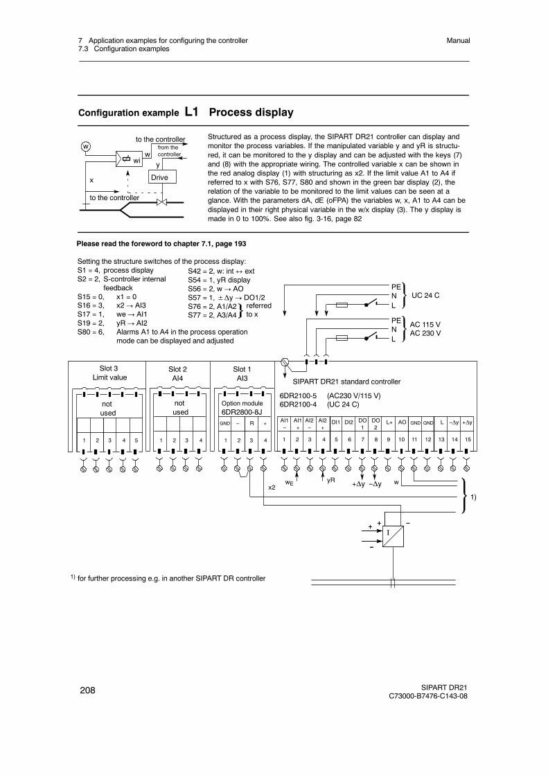
7 Application examples for configuring the controller7.3 Configuration examples
Manual
208 SIPART DR21C73000-B7476-C143-08
Configuration example L1 Process display
Structured as a process display, the SIPART DR21 controller can display andmonitor the process variables. If the manipulated variable y and yR is structu-red, it can be monitored to the y display and can be adjusted with the keys (7)and (8) with the appropriate wiring. The controlled variable x can be shown inthe red analog display (1) with structuring as x2. If the limit value A1 to A4 ifreferred to x with S76, S77, S80 and shown in the green bar display (2), therelation of the variable to be monitored to the limit values can be seen at aglance. With the parameters dA, dE (oFPA) the variables w, x, A1 to A4 can bedisplayed in their right physical variable in the w/x display (3). The y display ismade in 0 to 100%. See also fig. 3-16, page 82
w
y
Drive
wiw
x
to the controller
to the controllerfrom thecontroller
AI1--
PENL
PENL
UC 24 C
AC 115 VAC 230 V
AI1+
AI2--
AI2+
DI1 DI2 DO1
DO2
L+ AO
1 2 3 4 5 6 7 8 9 10 11 12
Setting the structure switches of the process display:S1 = 4, process displayS2 = 2, S-controller internal
feedbackS15 = 0, x1 = 0S16 = 3, x2! AI3S17 = 1, we! AI1S19 = 2, yR! AI2S80 = 6, Alarms A1 to A4 in the process operation
mode can be displayed and adjusted
Slot 1AI3
Slot 2AI4
Slot 3Limit value
1 2 3 4 5
notused
1 2 3 4
Option module6DR2800-8J
L +Δy
13 14 15
--Δy
Please read the foreword to chapter 7.1, page 193
SIPART DR21 standard controller
6DR2100-5 (AC230 V/115 V)6DR2100-4 (UC 24 C)
1 2 3 4
S42 = 2, w: int$ extS54 = 1, yR displayS56 = 2, w! AOS57 = 1,±Δy! DO1/2S76 = 2, A1/A2S77 = 2, A3/A4
referredto x
I--+
x2 +Δy --ΔywE yR
--
+
1)
notused
GND R-- +
1) for further processing e.g. in another SIPART DR controller
w
I--+
--
+
GND GND

7 Application examples for configuring the controller7.3 Configuration examples
Manual
SIPART DR21C73000-B7476-C143-08
209
Configuration example L1 process display (continued)
SIPART DR21
SIPART DR21SIEMENS
SP-W
OUT-Y
C
PVX
A1
A2
A3
A4
ADAPT
100
50
W
X
SPW
Adjusting keys ±Δy
3
1
2
7 8
9
14
15
6
19
11
12
13
16
17
18
Adjustment of setpoint with rapidaction
Controlledvariable x
Adaptation LED: off
Shift key: w/x display
Display CB signal
Internal LED: current status
Manual LED: current status
Shift key Manual/Tracking
Manual Ext/Tracking-LED
Analog displayLimit valuesA1 to A4
w/x displayvalues A1 to A4
yR displayor time valueA1 to A4
Shift key setpoint int$ ext
Limit value A1exceeded! flashes
A3
A1
A2
A4
20 Signal lamps for “limit value A1 to A4activated”
Process operation mode -- control and display elements in the setting as a process display
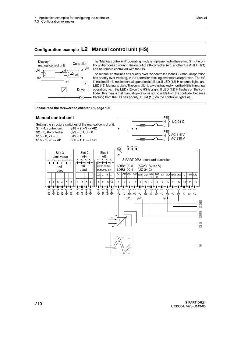
7 Application examples for configuring the controller7.3 Configuration examples
Manual
210 SIPART DR21C73000-B7476-C143-08
Configuration example L2 Manual control unit (HS)
Drive
y
wiyNyN
x2x1
yNController
Display/manual control unit
The “Manual control unit” operatingmode is implemented in thesettingS1= 4 (con-trol unit/process display). The output of a K-controller (e.g. another SIPARTDR21)can be remote controlled with the HS.
Themanual control unit has priority over the controller. In theHSmanual operationhas priority over tracking, in the controller tracking over manual operation. TheHSis tracked if it is not in manual operation itself, i.e. if LED (13) H external lights andLED (12)Manual is dark.The controller is always trackedwhen theHS is inmanualoperation, i.e. if the LED (12) on the HS is alight. If LED (12) H flashes on the con-troller, this means thatmanual operation is not possible fromthe controller becausetracking from the HS has priority. LEDd (13) on the controller lights up.
AI1--
PENL
PENL
UC 24 C
AC 115 VAC 230 V
AI1+
AI2--
AI2+
DI1 DI2 L+ AO
1 2 3 4 5 6 7 8 9 10 11 12
Slot 1AI3
Slot 2AI4
Slot 3Limit value
1 2 3 4 5 6
notused
1 2 3 4
Option module
6DR2800-8J
L +Δy
13 14 15
--Δy
SIPART DR21 standard controller
6DR2100-5 (AC230 V/115 V)6DR2100-4 (UC 24 C)
1 2 3 4
notused
R-- +
x2
I-- +
--
+
yN ly¡©¢
£
¥
¦§
Manual control unit
Setting the structure switches of the manual control unit:S1 = 4, control unit S18 = 2, yN$ AI2S2 = 0, K-controller S23 = 0, CB = 0S15 = 0, x1 = 0 S49 = 1S16 = 1, x2! AI1 S60 = 1, H! DO1
Please read the foreword to chapter 7.1, page 193
¤
¨
GND GND GNDDO1
DO2
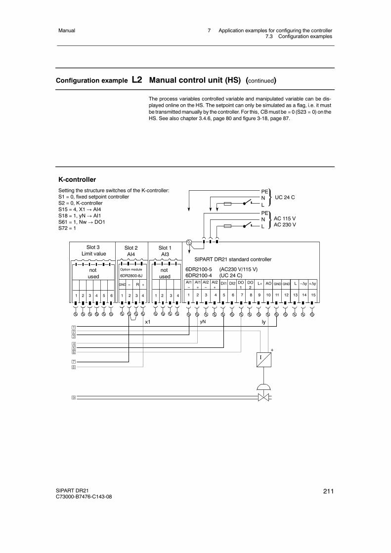
7 Application examples for configuring the controller7.3 Configuration examples
Manual
SIPART DR21C73000-B7476-C143-08
211
Configuration example L2 Manual control unit (HS) (continued)
The process variables controlled variable and manipulated variable can be dis-played online on the HS. The setpoint can only be simulated as a flag, i.e. it mustbe transmittedmanually by the controller. For this, CBmustbe = 0 (S23 = 0) on theHS. See also chapter 3.4.6, page 80 and figure 3-18, page 87.
AI1--
PENL
PENL
UC 24 C
AC 115 VAC 230 V
AI1+
AI2--
AI2+
DI1 DI2 L+ AO
1 2 3 4 5 6 7 8 9 10 11 12
Slot 1AI3
Slot 2AI4
Slot 3Limit value
1 2 3 4 5 6 1 2 3 4
Option module
6DR2800-8J
L +Δy
13 14 15
--Δy
SIPART DR21 standard controller
6DR2100-5 (AC230 V/115 V)6DR2100-4 (UC 24 C)
1 2 3 4
notused
R +
notused
--
I+
x1 lyyN¡©¢
¦§
¨
K-controller
Setting the structure switches of the K-controller:S1 = 0, fixed setpoint controllerS2 = 0, K-controllerS15 = 4, X1! AI4S18 = 1, yN! AI1S61 = 1, Nw! DO1S72 = 1
£
¥¤
GND GND GNDDO1
DO2

7 Application examples for configuring the controller7.3 Configuration examples
Manual
212 SIPART DR21C73000-B7476-C143-08
Configuration example L3 control unit (LG) with slave controller (FR)LG operates as a setpoint transmitter and manual control unitwith S-output.
With the LG the setpoint and theS-output of the slavecontroller canbe remotecon-trolled. The FR has priority with respect to setpoint andmanual operation. The set-point of the FR can only be set with the LG when the LED (17) internal, LED (18)cand LED (4) w display are alight. It is recommended to switch off the setpoint rampon the FR. Before switching over to setpoint presetting from the FR, you have towait for the setpoint set on the LG (max. 6 s).Parallel to the FR, the process variables setpoint, controller variable and positionfeedback can be displayed on the LG. x2 must be structured with S16 on the LGfor the analog x value display.
Drive
±Δy
w
x
F-controllerControl unit
ww±Δy
w
Please read the foreword to chapter 7.1, page 193
Control unit (LG)
Setting the structure switches of the control unit:S1 = 4, control unit S30 = 2, --yBL! DI2S2 = 0, S-controller i.Rf. S42 = 2, wi: int$ extS15 = 0, x1 = 0 S49 = 1S17 = 1, we! AI1 S54 = 1, yR displayS19 = 3, yR! AI3 S56 = 2, w! AOS22 = 1, Opt. Position 3 S57=1,±Δy! DO1/2S23 = 1, CB! DI1 S58 = 3, RB! DO3S25 = 0, N = 0 S60 = 4, H! DO4S26 = 0, Si = 0 S62 = 5, A1! DO5S29 = 2, +yBL! DI2 S63 = 6, A2! DO6
AI1--
PENL
PENL
UC 24 C
AC 115 VAC 230 V
AI1+
AI2--
AI2+
DI1 DI2 L+ AO
1 2 3 4 5 6 7 8 9 10 11 12
Slot 1AI3
Slot 2AI4
Slot 3
DI3DO3
DO6DI4DO
4DO5
1 2 3 4 5 6
notused
1 2 3 4
Option module
6DR2800-8J
L +Δy
13 14 15
--Δy
SIPART DR21 standard controller
6DR2100-5 (AC230 V/115 V)6DR2100-4 (UC 24 C)
1 2 3 4
R-- +
Option module
6DR2801-8E
A1A2
¡
©
¢
£
¥¦
¤
GND GND GNDDO1
DO2
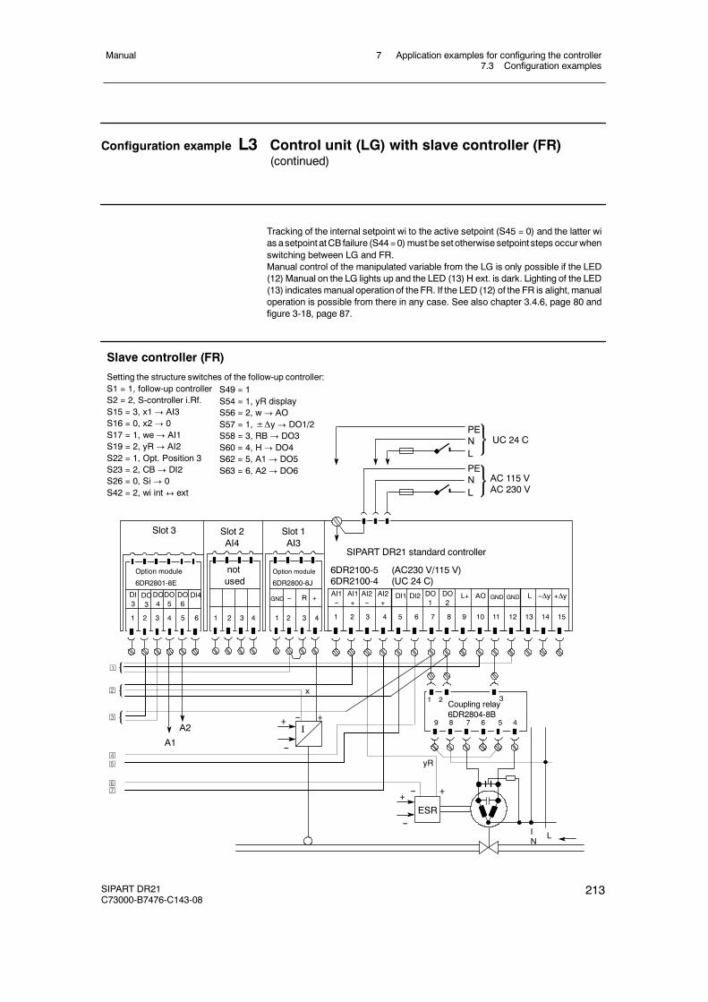
7 Application examples for configuring the controller7.3 Configuration examples
Manual
SIPART DR21C73000-B7476-C143-08
213
Configuration example L3 Control unit (LG) with slave controller (FR)(continued)
Tracking of the internal setpoint wi to the active setpoint (S45 = 0) and the latter wias asetpoint atCB failure (S44=0)must be set otherwise setpoint steps occurwhenswitching between LG and FR.Manual control of the manipulated variable from the LG is only possible if the LED(12) Manual on the LG lights up and the LED (13) H ext. is dark. Lighting of the LED(13) indicatesmanual operation of the FR. If the LED (12) of the FR is alight, manualoperation is possible from there in any case. See also chapter 3.4.6, page 80 andfigure 3-18, page 87.
AI1--
PENL
PENL
UC 24 C
AC 115 VAC 230 V
AI1+
AI2--
AI2+
DI1 DI2 L+ AO
1 2 3 4 5 6 7 8 9 10 11 12
Slot 1AI3
Slot 2AI4
Slot 3
1 2 3 4 5 6 1 2 3 4
Option module
6DR2800-8J
L +Δy
13 14 15
--Δy
SIPART DR21 standard controller
6DR2100-5 (AC230 V/115 V)6DR2100-4 (UC 24 C)
1 2 3 4
R +
notused
--
Option module
6DR2801-8E
DI3
DO3
DO6
DI4DO4DO5
A1
A2 I-- +
--
+
yR
1 2 3Coupling relay6DR2804-8B
9 8 7 6 5 4
-- +
--
+ESR
IN
L
Slave controller (FR)
Setting the structure switches of the follow-up controller:S1 = 1, follow-up controllerS2 = 2, S-controller i.Rf.S15 = 3, x1! AI3S16 = 0, x2! 0S17 = 1, we! AI1S19 = 2, yR! AI2S22 = 1, Opt. Position 3S23 = 2, CB ! DI2S26 = 0, Si ! 0S42 = 2, wi int $ ext
¡
©
¢
£
¥¦
¤
x
S49 = 1S54 = 1, yR displayS56 = 2, w! AOS57 = 1, ±Δy ! DO1/2S58 = 3, RB ! DO3S60 = 4, H! DO4S62 = 5, A1! DO5S63 = 6, A2! DO6
GND GND GNDDO1
DO2
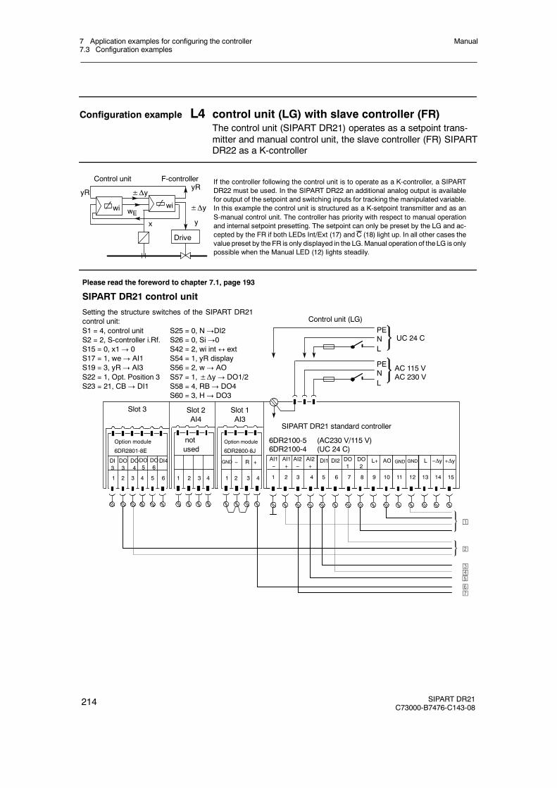
7 Application examples for configuring the controller7.3 Configuration examples
Manual
214 SIPART DR21C73000-B7476-C143-08
Configuration example L4 control unit (LG) with slave controller (FR)The control unit (SIPART DR21) operates as a setpoint trans-mitter and manual control unit, the slave controller (FR) SIPARTDR22 as a K-controller
If the controller following the control unit is to operate as a K-controller, a SIPARTDR22 must be used. In the SIPART DR22 an additional analog output is availablefor output of the setpoint and switching inputs for tracking the manipulated variable.In this example the control unit is structured as a K-setpoint transmitter and as anS-manual control unit. The controller has priority with respect to manual operationand internal setpoint presetting. The setpoint can only be preset by the LG and ac-cepted by the FR if both LEDs Int/Ext (17) and C (18) light up. In all other cases thevalue preset by the FR is only displayed in the LG. Manual operation of theLG is onlypossible when the Manual LED (12) lights steadily.
Drive
±Δy
x
F-controllerControl unit
wi wi
±ΔyyRyR
wEy
SIPART DR21 control unit
Setting the structure switches of the SIPART DR21control unit:S1 = 4, control unit S25 = 0, N!DI2S2 = 2, S-controller i.Rf. S26 = 0, Si!0S15 = 0, x1! 0 S42 = 2, wi int$ extS17 = 1, we! AI1 S54 = 1, yR displayS19 = 3, yR! AI3 S56 = 2, w! AOS22 = 1, Opt. Position 3 S57 = 1,±Δy! DO1/2S23 = 21, CB! DI1 S58 = 4, RB! DO4
S60 = 3, H! DO3
Control unit (LG)
AI1--
PENL
PENL
UC 24 C
AC 115 VAC 230 V
AI1+
AI2--
AI2+
DI1 DI2 L+ AO
1 2 3 4 5 6 7 8 9 10 11 12
Slot 1AI3
Slot 2AI4
Slot 3
DI3
DO3
DO6DI4DO
4DO5
1 2 3 4 5 6
notused
1 2 3 4
Option module
6DR2800-8J
L +Δy
13 14 15
--Δy
SIPART DR21 standard controller
6DR2100-5 (AC230 V/115 V)6DR2100-4 (UC 24 C)
1 2 3 4
R-- +
Option module
6DR2801-8E
Please read the foreword to chapter 7.1, page 193
¡
©
¢£
¥¦
¤
GND GND GNDDO1
DO2
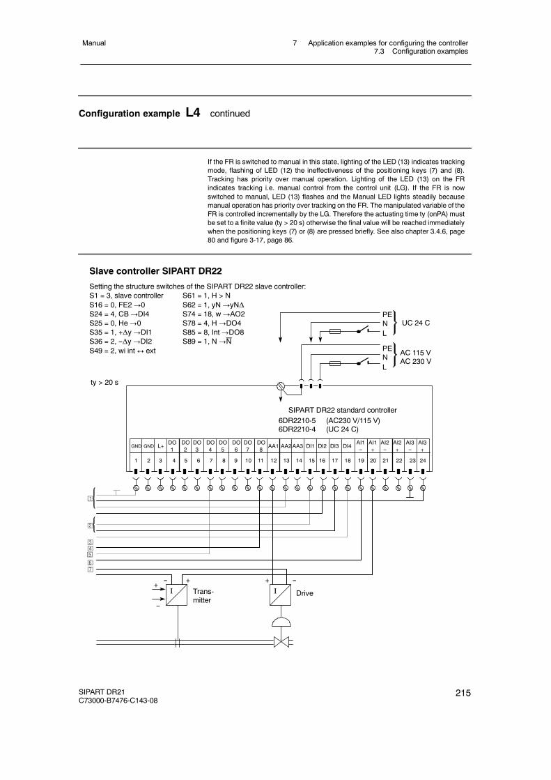
7 Application examples for configuring the controller7.3 Configuration examples
Manual
SIPART DR21C73000-B7476-C143-08
215
Configuration example L4 continued
If the FR is switched to manual in this state, lighting of the LED (13) indicates trackingmode, flashing of LED (12) the ineffectiveness of the positioning keys (7) and (8).Tracking has priority over manual operation. Lighting of the LED (13) on the FRindicates tracking i.e. manual control from the control unit (LG). If the FR is nowswitched to manual, LED (13) flashes and the Manual LED lights steadily becausemanual operation has priority over tracking on the FR. The manipulated variable of theFR is controlled incrementally by the LG. Therefore the actuating time ty (onPA) mustbe set to a finite value (ty > 20 s) otherwise the final value will be reached immediatelywhen the positioning keys (7) or (8) are pressed briefly. See also chapter 3.4.6, page80 and figure 3-17, page 86.
Slave controller SIPART DR22
Setting the structure switches of the SIPART DR22 slave controller:S1 = 3, slave controller S61 = 1, H > NS16 = 0, FE2!0 S62 = 1, yN!yNΔS24 = 4, CB!DI4 S74 = 18, w!AO2S25 = 0, He!0 S78 = 4, H!DO4S35 = 1, +Δy!DI1 S85 = 8, Int!DO8S36 = 2, --Δy!DI2 S89 = 1, N!NS49 = 2, wi int$ ext
AI1--
PENL
PENL
UC 24 C
AC 115 VAC 230 V
AI1+
1 2 3 4 5 6 7 8 9 10 11 12 13 14 15
SIPART DR22 standard controller6DR2210-5 (AC230 V/115 V)6DR2210-4 (UC 24 C)
16 17 18 19 20 21 22 23 24
L+ AA1 AA2AA3 DI1 DI2 DI3 DI4AI2--
AI2+
AI3--
AI3+
ty > 20 s
I-- +
I--+
DriveTrans-mitter
--
+
¡
©
¢£
¥¦
¤
GND GNDDO1
DO2
DO3
DO4
DO5
DO6
DO7
DO8
7 Application examples for configuring the controller7.4 Configuring tool, forms
Manual
216 SIPART DR21C73000-B7476-C143-08
7.4 Configuring tool, forms
We recommend the following procedure for solving your controller problems:
- Determining the assembly of the controller- If necessary: Determining the position of bridges and switches on the backplane module and
signal transformers- Drawing the wiring diagram- Enter settings further down in the onPA, ofPA and Stru list (structuring, parameterizing)- The SIMATIC PDM program is available for PC-supported configurations.
For notes

7 Application examples for configuring the controller7.4 Configuring tool, forms
Manual
SIPART DR21C73000-B7476-C143-08
217
Circuit design K/S-controller 6DR2100-4/-5
Slot 1AI3
Slot 2AI4
notused
Slot 3Limit value
Option module6DR2801-8D
M1 A1 R2 M2R1 A2
1 2 3 4 5 6
notused
AI1--
PENL
SIPART DR21 standard controller
PENL
UC 24 C
AC 115 VAC 230 V
6DR2100-5 (AC230 V/115 V)6DR2100-4 (UC 24 C)
AI1+
AI2--
AI2+
DI1 DI2 DO1
DO2
L+ AO
1 2 3 4 5 6 7 8 9 10 11 12
-ΔyL
13 14 15
+Δy
1 2 3 4 1 2 3 4
R
C
Spark quench-ing internal
GND GND
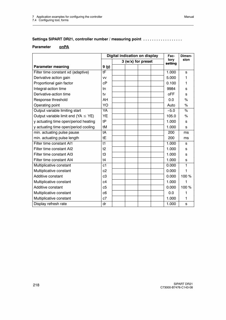
7 Application examples for configuring the controller7.4 Configuring tool, forms
Manual
218 SIPART DR21C73000-B7476-C143-08
Settings SIPART DR21, controller number / measuring point . . . . . . . . . . . . . . . . . .
Parameter onPA
Digital indication on display Fac-t
Dimen-i3 (w/x) for preset tory
settingsion
Parameter meaning 9 (y)setting
Filter time constant xd (adaptive) tF 1.000 s( p )Derivative action gain vv 5.000 1gProportional gain factor cP 0.100 1p gIntegral-action time tn 9984 sgDerivative-action time tv oFF sResponse threshold AH 0.0 %pOperating point YO Auto %Output variable limiting start YA --5.0 %p gOutput variable limit end (YA≤ YE) YE 105.0 %p ( )y actuating time open/period heating tP 1.000 sy g p p gy actuating time open/period cooling tM 1.000 smin. actuating pulse pause tA 200 msg p pmin. actuating pulse length tE 200 msFilter time constant AI1 t1 1.000 sFilter time constant AI2 t2 1.000 sFilter time constant AI3 t3 1.000 sFilter time constant AI4 t4 1.000 sMultiplicative constant c1 0.000 1pMultiplicative constant c2 0.000 1pAdditive constant c3 0.000 100 %Multiplicative constant c4 1.000 1pAdditive constant c5 0.000 100 %Multiplicative constant c6 0.0 1pMultiplicative constant c7 1.000 1Display refresh rate dr 1.000 s

7 Application examples for configuring the controller7.4 Configuring tool, forms
Manual
SIPART DR21C73000-B7476-C143-08
219
Settings SIPART DR21, controller number / measuring point . . . . . . . . . . . . . . . . . .
Parameter oFPA
Digital indication on display Fac-t
Dimen-i3 (w/x) for preset tory
settingsion
Parameter meaning 9 (y)setting
Decimal point w/x display dP --p p yStart of scale dA 0.0 --Full scale dE 100.0 --Alarm 1 A1 5,0 --Alarm 2 (A2≤ A1) A2
,--5,0 --( )
Alarm 3 A3,
5,0 --Alarm 4 (A4≤ A3) A4
,--5,0 --( )
Hysteresis alarms HA,1 %
Setpoint limit start SA --5,0 --pSetpoint limit end SE
,105,0 --p
Safety setpoint SH,
0,0 --Setpoint ramp time tS oFF minRatio factor start vA 0,000 1Ratio factor end vE
,1,000 1
Safety output variable YS 0,0 %y pSplit range left y1 (y1≤ y2) Y1
,50,0 %p g y (y y )
Split range right y2 Y2,
50,0 %Vertex value at --10 %V l 0 %
L--1L0
--100
%%Vertex value at 0 %
Vertex value at 10 %L0L1
010
%%Vertex value at 10 %
Vertex value at 20 %L1L2
1020
%%Vertex value at 20 %
Vertex value at 30 %L2L3
2030
%%Vertex value at 30 %
Vertex value at 40 %L3L4
3040
%%
Vertex value at 50 % L5 50 %Vertex value at 60 %Vertex value at 70 %
L6L7
6070
%%Vertex value at 70 %
Vertex value at 80 %L7L8
7080
%%Vertex value at 80 %
Vertex value at 90 %L8L9
8090
%%Vertex value at 90 %
Vertex value at 100 %L9L10
90100
%%
Vertex value at 110 % L11 110 %
Decimal point Pd --pStart of scale Ad 0,0 --Full scale (only at S1 = 3) Ed
,100,0 --
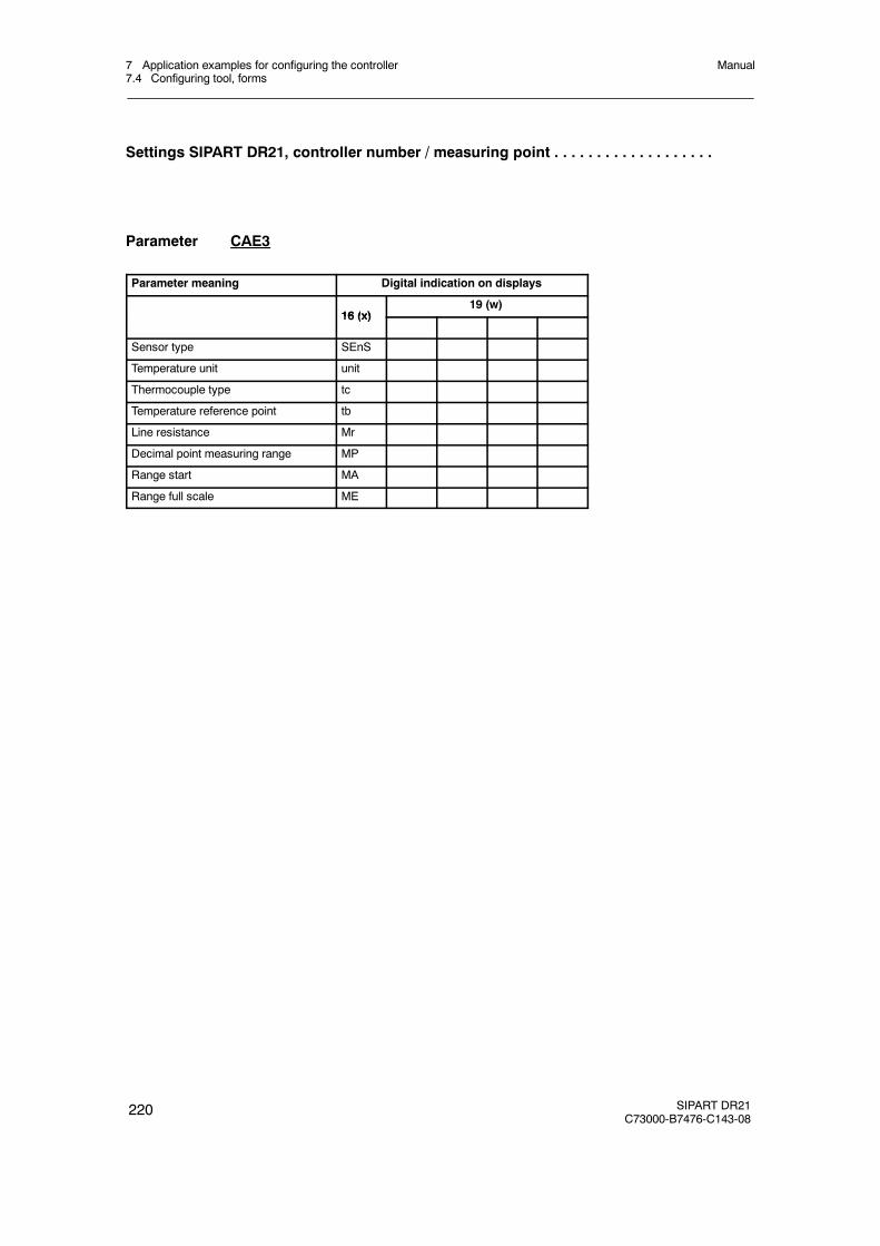
7 Application examples for configuring the controller7.4 Configuring tool, forms
Manual
220 SIPART DR21C73000-B7476-C143-08
Settings SIPART DR21, controller number / measuring point . . . . . . . . . . . . . . . . . . .
Parameter CAE3
Parameter meaning Digital indication on displays
16 (x)19 (w)
16 (x)
Sensor type SEnS
Temperature unit unit
Thermocouple type tc
Temperature reference point tb
Line resistance Mr
Decimal point measuring range MP
Range start MA
Range full scale ME
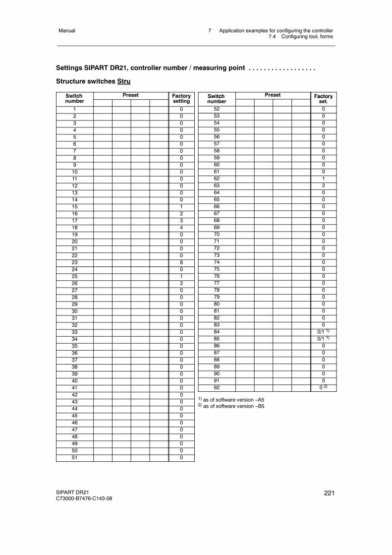
7 Application examples for configuring the controller7.4 Configuring tool, forms
Manual
SIPART DR21C73000-B7476-C143-08
221
Settings SIPART DR21, controller number / measuring point . . . . . . . . . . . . . . . . . .
Structure switches Stru
Switchb
Preset Factoryi
Switchnumber
Factorysetting
1 02 03 04 05 06 07 08 09 010 011 012 013 014 015 116 217 318 419 020 021 022 023 824 025 126 227 028 029 030 031 032 033 034 035 036 037 038 039 040 041 042 043 044 045 046 047 048 049 050 051 0
Switch Preset FactorySwitchnumber
Factoryset.
52 053 054 055 056 057 058 059 060 061 062 163 264 065 066 067 068 069 070 071 072 073 074 075 076 077 078 079 080 081 082 083 084 0/1 1)
85 0/1 1)
86 087 088 089 090 091 092 0 2)
1) as of software version --A52) as of software version --B5

7 Application examples for configuring the controller7.4 Configuring tool, forms
Manual
222 SIPART DR21C73000-B7476-C143-08
8 Maintenance8.1 General information and handling
Manual
SIPART DR21C73000-B7476-C143-08
223
8 Maintenance
8.1 General information and handling
The controller is maintenance-free. White spirit or industrial alcohol is recommended for clean-ing the front foil and the plastic housing if necessary.
be changed freely without readjustment with power supplied. The other modules may also bereplaced without readjustment (procedure as described in chapter 8.2).
CAUTION
All modules contain components which are vulnerable to static. Observe thesafety precautions!
S-actuators on S-controllers remain in their last position.
!WARNING
The backplane module may only be changed after the power supply has beensafely disconnected.
!WARNING
Modules may only be repaired in an authorized workshop. This applies particu-larly to the backplane module because of the safety functions (safe disconnec-tion and safety extra low voltages).
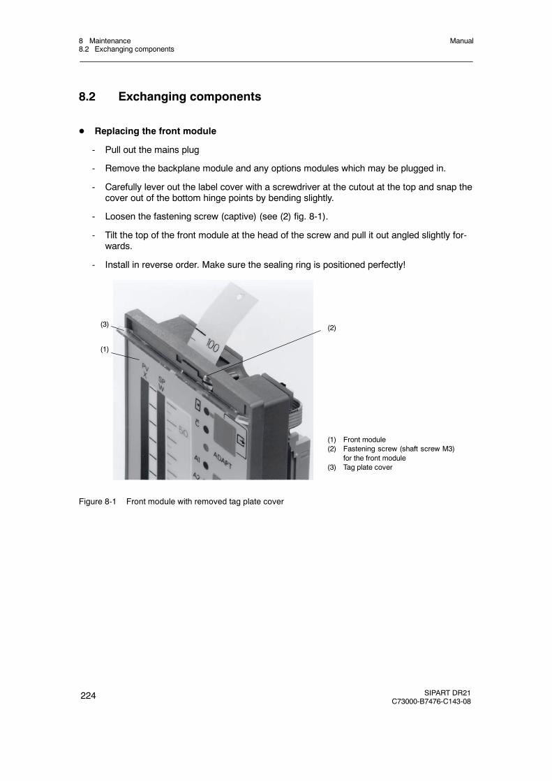
8 Maintenance8.2 Exchanging components
Manual
224 SIPART DR21C73000-B7476-C143-08
8.2 Exchanging components
D Replacing the front module
- Pull out the mains plug
- Remove the backplane module and any options modules which may be plugged in.
- Carefully lever out the label cover with a screwdriver at the cutout at the top and snap thecover out of the bottom hinge points by bending slightly.
- Loosen the fastening screw (captive) (see (2) fig. 8-1).
- Tilt the top of the front module at the head of the screw and pull it out angled slightly for-wards.
- Install in reverse order. Make sure the sealing ring is positioned perfectly!
(1) Front module(2) Fastening screw (shaft screw M3)
for the front module(3) Tag plate cover
(2)
(1)
(3)
Figure 8-1 Front module with removed tag plate cover

8 Maintenance8.2 Exchanging components
Manual
SIPART DR21C73000-B7476-C143-08
225
D Replacing the options modules
- Pull off the plug terminals.
- Release the lock and remove the options module (see (6) figure 8-2).
- Push in the new module to the stop and lock it (the modules are slot coded). Pleasemake sure the right modules are plugged into the slots provided for the different options(see chapter 2.4, page 24).
- Plug in the terminal (pay attention to slot labeling!),
(1) Front module(2) Plastic housing(3) Module locked(4) Dummy cover(5) Terminals(6) Module unlocked(7) Fastening screw for the
backplane-module(8) Terminal 4-pole(9) Terminal 8-pole(10) Terminal 3-pole(6) (5) (3)(4)
(7)
(8)
(9)
(10)
(1)
(2)
Figure 8-2 Controller rear view
D Replacement of the backplane module (power supply unit + basic circuit board)
- Pull out the mains plug!
- Pull off the plug terminals.
- Disconnect the PE conductor
- Loosen the fastening screw of the backplane module (see (2) fig. 8-2) and pull out themodule.
- Install in reverse order.

8 Maintenance8.3 LED-test and software version
Manual
226 SIPART DR21C73000-B7476-C143-08
D Disconnect the power supply unit from the basic circuit board(Components of the backplane module)
- Pull out the backplane module (see replacement of the backplane module)
- Pull out the ribbon cable plug (see (5) figue 8-3)
- Loosen the fastening screw of the basic circuit board (see (7) figure 8-3).
- Separate the basic circuit board and the power supply unit.
- Re-assemble in reverse order.(Pay attention to correct plugging of jumpers (see (3) figure 8-3))
(1) Connecting plug
(2) Fastening screw for thebackplane module
(3) Plug--in jumpers
(4) Power supply unit
(5) Plug ribbon cable
(6) Basic circuit board
(7) Fastening screws for theBasic circuit board
(7)(6)
(5)
(4)(3) (2)
(1)
Figure 8-3 Backplane module
8.3 LED-test and software version
If the Shift key (6) is pressed for about 10 s (“PS” flashes on the manipulated variable displayafter about 5 s), this leads to the LED-test. All LEDs light up, the displays show “8.8.8.8.” or“88.” and a light marker covering 2 LEDs runs from 0 to 100% on both bargraphs (on reaching100% it starts again at 0%).
If the Internal-/External key (16) is additionally pressed permanently during the lamp test, “dr21”appears on the digital x/w-display and the controller software version on the digital y-display.
During the LED-test and display of the software version the controller continues to operate on-line in its last operating mode.
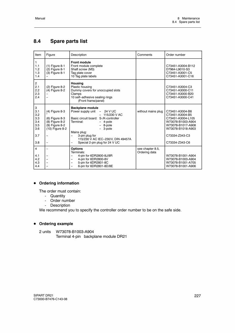
8 Maintenance8.4 Spare parts list
Manual
SIPART DR21C73000-B7476-C143-08
227
8.4 Spare parts list
Item Figure Description Comments Order number
11.11.21.31.4
(1) Figure 8-1(2) Figure 8-1(3) Figure 8-1--
Front moduleFront module completeShaft screw (M3)Tag plate cover10 Tag plate labels
C73451-A3004-B112D7964-L9010-S3C73451-A3001-C5C73451-A3001-C16
22.12.22.32.4
(2) Figure 8-2(4) Figure 8-2----
HousingPlastic housingDummy covers for unoccupied slotsClamps10 self--adhesive sealing rings
(Front frame/panel)
C73451-A3004-C3C73451-A3000-C11C73451-A3000-B20C73451-A3000-C41
33.13.23.33.43.53.6
3.7
3.8
(4) Figure 8-3”(6) Figure 8-3(8) Figure 8-2(9) Figure 8-2(10) Figure 8-2
--
--
Backplane modulePower supply unit -- 24 V UC
-- 115/230 V ACBasic circuit board: S-/K-controllerTerminal: -- 4-pole
-- 8-pole-- 3-pole
Mains plug:-- 3-pin plug for
115/230 V AC IEC--230/V, DIN 49457A-- Special 2-pin plug for 24 V UC
without mains plug C73451-A3004-B8C73451-A3004-B5C73451-A3004-L105W73078-B1003-A904W73078-B1017-A908W73078-B1018-A903
C73334-Z343-C3
C73334-Z343-C6
4
4.14.24.34.4
--
--------
OptionsTerminals:-- 4-pin for 6DR2800-8J/8R-- 4-pin for 6DR2800-8V-- 5-pin for 6DR2801-8C-- 6-pin for 6DR2801-8D/8E
see chapter 8.5,Ordering data
W73078-B1001-A904W73078-B1003-A904W73078-B1001-A705W73078-B1001-A906
D Ordering information
The order must contain:- Quantity- Order number- Description
We recommend you to specify the controller order number to be on the safe side.
D Ordering example
2 units W73078-B1003-A904Terminal 4-pin backplane module DR21
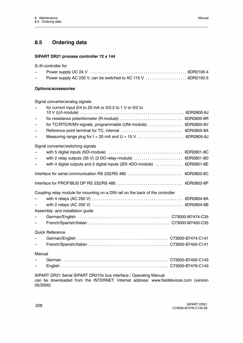
8 Maintenance8.5 Ordering data
Manual
228 SIPART DR21C73000-B7476-C143-08
8.5 Ordering data
SIPART DR21 process controller 72 x 144
S-/K-controller for-- Power supply UC 24 V 6DR2100-4. . . . . . . . . . . . . . . . . . . . . . . . . . . . . . . . . . . . . . . . . . . . . . .-- Power supply AC 230 V, can be switched to AC 115 V 6DR2100-5. . . . . . . . . . . . . . . . . . . .
Options/accessories
Signal converter/analog signals-- for current input 0/4 to 20 mA or 0/0.2 to 1 V or 0/2 to
10 V (U/I-module) 6DR2800-8J. . . . . . . . . . . . . . . . . . . . . . . . . . . . . . . . . . . . . . . . . . . . . . . . . . .-- for resistance potentiometer (R-module) 6DR2800-8R. . . . . . . . . . . . . . . . . . . . . . . . . . . . . .-- for TC/RTD/R/MV-signals, programmable (UNI-module) 6DR2800-8V. . . . . . . . . . . . . . . . .-- Reference point terminal for TC, internal 6DR2805-8A. . . . . . . . . . . . . . . . . . . . . . . . . . . . . .-- Measuring range plug for I = 20 mA and U = 10 V 6DR2805-8J. . . . . . . . . . . . . . . . . . . . . . .
Signal converter/switching signals-- with 5 digital inputs (5DI-module) 6DR2801-8C. . . . . . . . . . . . . . . . . . . . . . . . . . . . . . . . . . . .-- with 2 relay outputs (35 V) (2 DO-relay-module) 6DR2801-8D. . . . . . . . . . . . . . . . . . . . . . . .-- with 4 digital outputs and 2 digital inputs (2DI 4DO-module) 6DR2801-8E. . . . . . . . . . . . .
Interface for serial communication RS 232/RS 485 6DR2803-8C. . . . . . . . . . . . . . . . . . . . . . . . . . .
Interface for PROFIBUS DP RS 232/RS 485 6DR2803-8P. . . . . . . . . . . . . . . . . . . . . . . . . . . . . . . .
Coupling relay module for mounting on a DIN rail on the back of the controller-- with 4 relays (AC 250 V) 6DR2804-8A. . . . . . . . . . . . . . . . . . . . . . . . . . . . . . . . . . . . . . . . . . . .-- with 2 relays (AC 250 V) 6DR2804-8B. . . . . . . . . . . . . . . . . . . . . . . . . . . . . . . . . . . . . . . . . . . .Assembly- and installation guide-- German/English C73000-M7474-C35. . . . . . . . . . . . . . . . . . . . . . . . . . . . . . . . . . . . . . . . . . . . .-- French/Spanish/Italian C73000-M7450-C35. . . . . . . . . . . . . . . . . . . . . . . . . . . . . . . . . . . . . . . .
Quick Reference-- German/English C73000-B7474-C141. . . . . . . . . . . . . . . . . . . . . . . . . . . . . . . . . . . . . . . . . . . .-- French/Spanish/Italian C73000-B7450-C141. . . . . . . . . . . . . . . . . . . . . . . . . . . . . . . . . . . . . . .
Manual-- German C73000-B7400-C143. . . . . . . . . . . . . . . . . . . . . . . . . . . . . . . . . . . . . . . . . . . . . . . . . . .-- English C73000-B7476-C143. . . . . . . . . . . . . . . . . . . . . . . . . . . . . . . . . . . . . . . . . . . . . . . . . . . .
SIPART DR21 Serial SIPART DR210x bus interface / Operating Manualcan be downloaded from the INTERNET. Internet address: www.fielddevices.com (version05/2000)

9 General explanation of abbreviations for SIPART DRManual
SIPART DR21C73000-B7476-C143-08
229
9 General explanation of abbreviations for SIPART DR
A control signal no automatic mode. . . . . . . . . . . . . . . . .A* Parameter Alarms (limit values). . . . . . . . . . . . . . . .Ad . . . . . . . . . . . . . . . . .AdAP Parameterization mode Adaptation. . . . . . . . . . . . .AdAPT LED, adaptation mode. . . . . . . . . . . .AH* Response threshold (dead zone). . . . . . . . . . . . . .AI* Analog inputs. . . . . . . . . . . . . . .AI*A Outputs of the analog inputs. . . . . . . . . . . . . .AO Analog output. . . . . . . . . . . . . . .APSt Structuring mode All Preset (whole controller to factory setting). . . . . . . . . . . . .AUto automatic. . . . . . . . . . . . . .Ar* Function block, Arithmetic. . . . . . . . . . . . . . .
bLb Control signal, Blocking, Operating. . . . . . . . . . . . . . .bLPS Control signal, Blocking, Parameterization/Structuring. . . . . . . . . . . . .bLPSDI Control signal, Blocking, Parameterization/Structuring via digital input. . . . . . . . . . . .bLPSES Control signal, Blocking, Parameterization/Structuring via SES. . . . . . . . . . .bLS Control signal, Blocking, Structuring. . . . . . . . . . . . . .bLSDI Control signal, Blocking, Structuring via digital input. . . . . . . . . . . . .bLSES Control signal, Blocking, Structuring via SES. . . . . . . . . . . .
c* Parameter, Constants. . . . . . . . . . . . . . . .C LED, no computer standby. . . . . . . . . . . . . . . . .CA Calibration, start of range. . . . . . . . . . . . . . .CAE3 Parameterization mode, UNI-module. . . . . . . . . . . . .CB Control signal, Computer operation. . . . . . . . . . . . . . .CBDI Control signal, Computer operation via digital inputs. . . . . . . . . . . . . .CBES Control signal, Computer operation via SES. . . . . . . . . . . . .cP (Kp) Proportional action factor. . . . . . . . . . . . . . . .CPU central processing unit. . . . . . . . . . . . . .Cr Calibration, adjustment of line resistances (RL). . . . . . . . . . . . . . . .
dA Parameter, display range, start. . . . . . . . . . . . . . . .DDC direct digital control. . . . . . . . . . . . . .dE Parameter, display range, end. . . . . . . . . . . . . . . .DI** Digital inputs. . . . . . . . . . . . . .DO** Digital outputs. . . . . . . . . . . . .dP Parameter, display decimal point. . . . . . . . . . . . . . . .dPv Parameter direction of step command. . . . . . . . . . . . . . .dr Parameter, display refresh rate. . . . . . . . . . . . . . . .dY Parameter amplitude of the step command. . . . . . . . . . . . . . . .
Ed . . . . . . . . . . . . . . . . .End Error message end. . . . . . . . . . . . . .
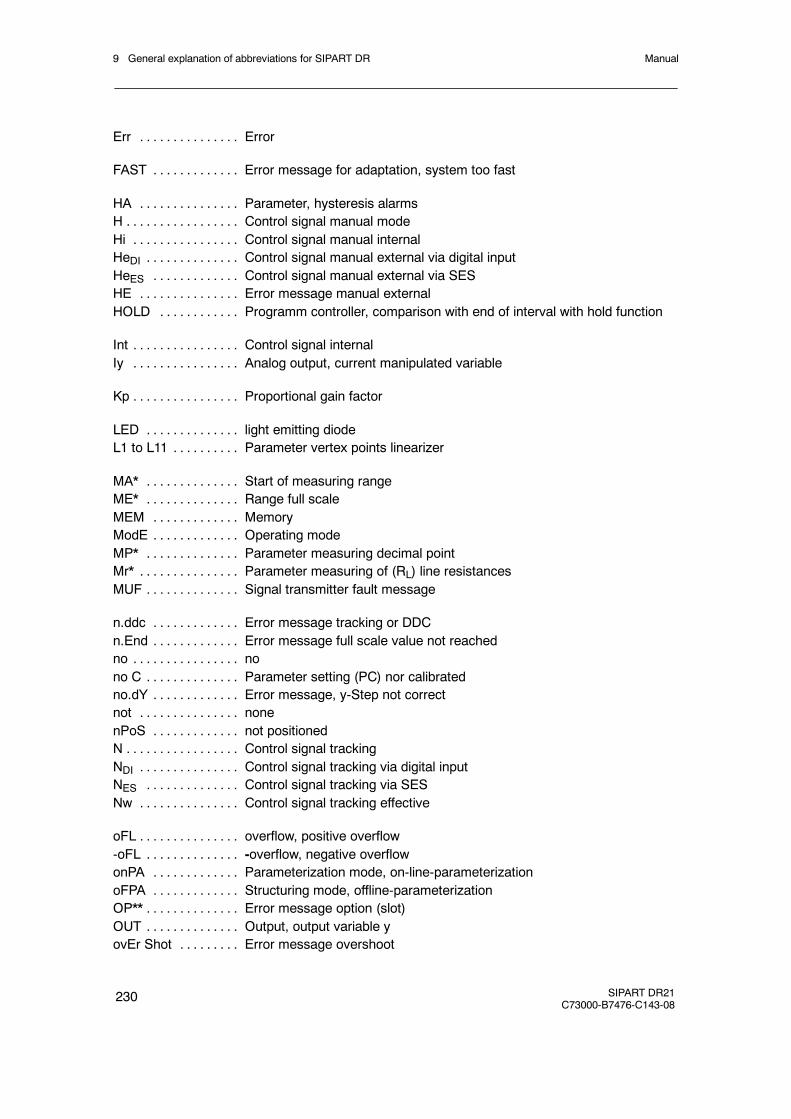
9 General explanation of abbreviations for SIPART DR Manual
230 SIPART DR21C73000-B7476-C143-08
Err Error. . . . . . . . . . . . . . .
FAST Error message for adaptation, system too fast. . . . . . . . . . . . .
HA Parameter, hysteresis alarms. . . . . . . . . . . . . . .H Control signal manual mode. . . . . . . . . . . . . . . . .Hi Control signal manual internal. . . . . . . . . . . . . . . .HeDI Control signal manual external via digital input. . . . . . . . . . . . . .HeES Control signal manual external via SES. . . . . . . . . . . . .HE Error message manual external. . . . . . . . . . . . . . .HOLD Programm controller, comparison with end of interval with hold function. . . . . . . . . . . .
Int Control signal internal. . . . . . . . . . . . . . . .Iy Analog output, current manipulated variable. . . . . . . . . . . . . . . .
Kp Proportional gain factor. . . . . . . . . . . . . . . .
LED light emitting diode. . . . . . . . . . . . . .L1 to L11 Parameter vertex points linearizer. . . . . . . . . .
MA* Start of measuring range. . . . . . . . . . . . . .ME* Range full scale. . . . . . . . . . . . . .MEM Memory. . . . . . . . . . . . .ModE Operating mode. . . . . . . . . . . . .MP* Parameter measuring decimal point. . . . . . . . . . . . . .Mr* Parameter measuring of (RL) line resistances. . . . . . . . . . . . . . .MUF Signal transmitter fault message. . . . . . . . . . . . . .
n.ddc Error message tracking or DDC. . . . . . . . . . . . .n.End Error message full scale value not reached. . . . . . . . . . . . .no no. . . . . . . . . . . . . . . .no C Parameter setting (PC) nor calibrated. . . . . . . . . . . . . .no.dY Error message, y-Step not correct. . . . . . . . . . . . .not none. . . . . . . . . . . . . . .nPoS not positioned. . . . . . . . . . . . .N Control signal tracking. . . . . . . . . . . . . . . . .NDI Control signal tracking via digital input. . . . . . . . . . . . . . .NES Control signal tracking via SES. . . . . . . . . . . . . .Nw Control signal tracking effective. . . . . . . . . . . . . . .
oFL overflow, positive overflow. . . . . . . . . . . . . . .-oFL -overflow, negative overflow. . . . . . . . . . . . . .onPA Parameterization mode, on-line-parameterization. . . . . . . . . . . . .oFPA Structuring mode, offline-parameterization. . . . . . . . . . . . .OP** Error message option (slot). . . . . . . . . . . . . .OUT Output, output variable y. . . . . . . . . . . . . .ovEr Shot Error message overshoot. . . . . . . . .
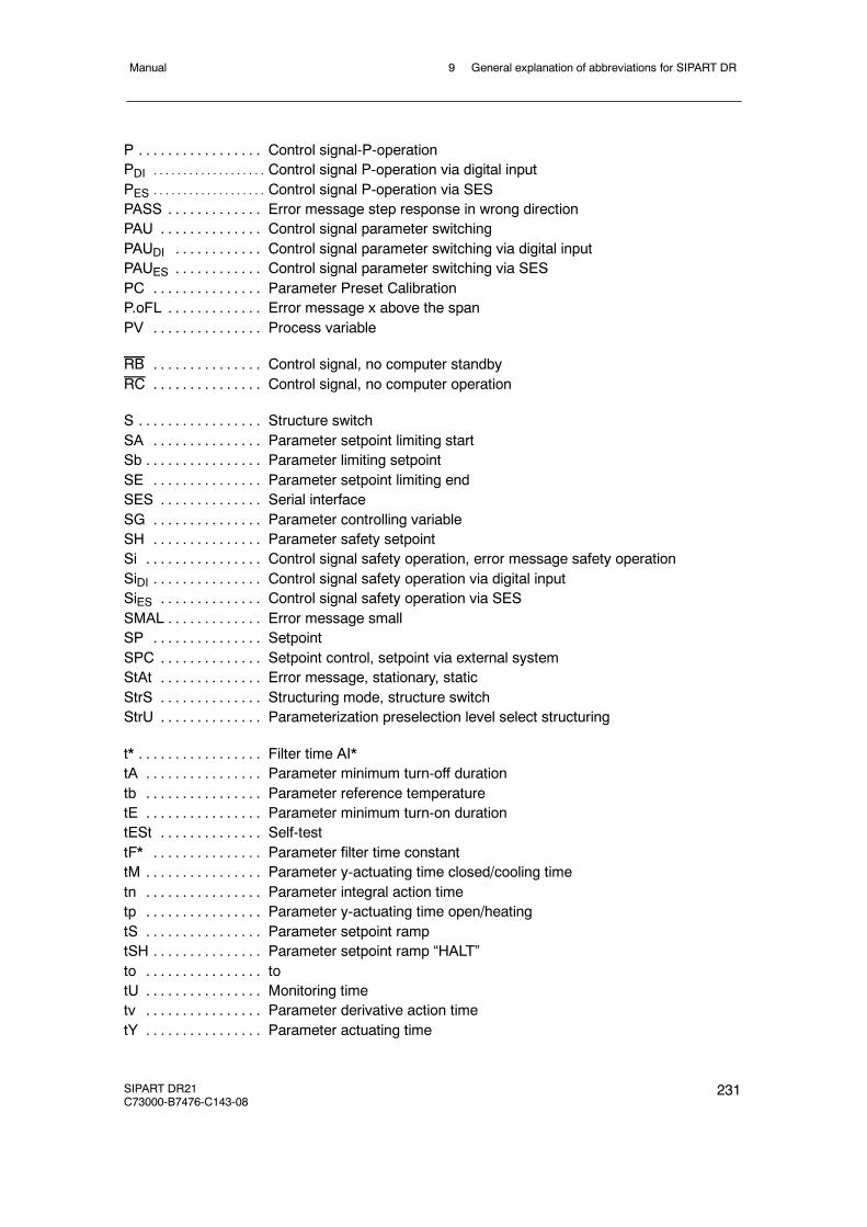
9 General explanation of abbreviations for SIPART DRManual
SIPART DR21C73000-B7476-C143-08
231
P Control signal-P-operation. . . . . . . . . . . . . . . . .PDI Control signal P-operation via digital input. . . . . . . . . . . . . . . . . . .
PES Control signal P-operation via SES. . . . . . . . . . . . . . . . . . .
PASS Error message step response in wrong direction. . . . . . . . . . . . .PAU Control signal parameter switching. . . . . . . . . . . . . .PAUDI Control signal parameter switching via digital input. . . . . . . . . . . .PAUES Control signal parameter switching via SES. . . . . . . . . . . .PC Parameter Preset Calibration. . . . . . . . . . . . . . .P.oFL Error message x above the span. . . . . . . . . . . . .PV Process variable. . . . . . . . . . . . . . .
RB Control signal, no computer standby. . . . . . . . . . . . . . .RC Control signal, no computer operation. . . . . . . . . . . . . . .
S Structure switch. . . . . . . . . . . . . . . . .SA Parameter setpoint limiting start. . . . . . . . . . . . . . .Sb Parameter limiting setpoint. . . . . . . . . . . . . . . .SE Parameter setpoint limiting end. . . . . . . . . . . . . . .SES Serial interface. . . . . . . . . . . . . .SG Parameter controlling variable. . . . . . . . . . . . . . .SH Parameter safety setpoint. . . . . . . . . . . . . . .Si Control signal safety operation, error message safety operation. . . . . . . . . . . . . . . .SiDI Control signal safety operation via digital input. . . . . . . . . . . . . . .SiES Control signal safety operation via SES. . . . . . . . . . . . . .SMAL Error message small. . . . . . . . . . . . .SP Setpoint. . . . . . . . . . . . . . .SPC Setpoint control, setpoint via external system. . . . . . . . . . . . . .StAt Error message, stationary, static. . . . . . . . . . . . . .StrS Structuring mode, structure switch. . . . . . . . . . . . . .StrU Parameterization preselection level select structuring. . . . . . . . . . . . . .
t* Filter time AI*. . . . . . . . . . . . . . . . .tA Parameter minimum turn-off duration. . . . . . . . . . . . . . . .tb Parameter reference temperature. . . . . . . . . . . . . . . .tE Parameter minimum turn-on duration. . . . . . . . . . . . . . . .tESt Self-test. . . . . . . . . . . . . .tF* Parameter filter time constant. . . . . . . . . . . . . . .tM Parameter y-actuating time closed/cooling time. . . . . . . . . . . . . . . .tn Parameter integral action time. . . . . . . . . . . . . . . .tp Parameter y-actuating time open/heating. . . . . . . . . . . . . . . .tS Parameter setpoint ramp. . . . . . . . . . . . . . . .tSH Parameter setpoint ramp “HALT”. . . . . . . . . . . . . . .to to. . . . . . . . . . . . . . . .tU Monitoring time. . . . . . . . . . . . . . . .tv Parameter derivative action time. . . . . . . . . . . . . . . .tY Parameter actuating time. . . . . . . . . . . . . . . .
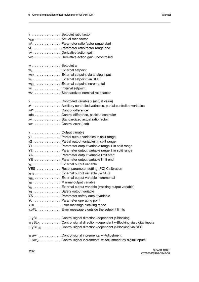
9 General explanation of abbreviations for SIPART DR Manual
232 SIPART DR21C73000-B7476-C143-08
v Setpoint ratio factor. . . . . . . . . . . . . . . . .vact Actual ratio factor. . . . . . . . . . . . . . .vA Parameter ratio factor range start. . . . . . . . . . . . . . . .vE Parameter ratio factor range end. . . . . . . . . . . . . . . .vv Derivative action gain. . . . . . . . . . . . . . . .vvc Derivative action gain uncontrolled. . . . . . . . . . . . . . .
w Setpoint w. . . . . . . . . . . . . . . . .wE External setpoint. . . . . . . . . . . . . . . .wEA External setpoint via analog input. . . . . . . . . . . . . .wES External setpoint via SES. . . . . . . . . . . . . .wEΔ External setpoint incremental. . . . . . . . . . . . . .wi Internal setpoint. . . . . . . . . . . . . . . .wv Standardized nominal ratio factor. . . . . . . . . . . . . . . .
x Controlled variable x (actual value). . . . . . . . . . . . . . . . .x* Auxiliary controlled variables, partial controlled variables. . . . . . . . . . . . . . . .xd* Control difference. . . . . . . . . . . . . . .xds Control difference, position controller. . . . . . . . . . . . . . .xv Standardized actual ratio factor. . . . . . . . . . . . . . . .xw Control error (--xd). . . . . . . . . . . . . . . .
y Output variable. . . . . . . . . . . . . . . . .y1 Partial output variables in split range. . . . . . . . . . . . . . . .y2 Partial output variables in split range. . . . . . . . . . . . . . . .Y1 Parameter output variable range 1 in split range. . . . . . . . . . . . . . . .Y2 Parameter output variable range 2 in split range. . . . . . . . . . . . . . . .YA Parameter output variable limit start. . . . . . . . . . . . . . .YE Parameter output variable limit end. . . . . . . . . . . . . . .yE External output variable. . . . . . . . . . . . . . . .YES Reset parameter setting (PC) Calibration. . . . . . . . . . . . . .yES External output variable via SES. . . . . . . . . . . . . . .yEΔ External output variable incremental. . . . . . . . . . . . . . .yH Manual output variable. . . . . . . . . . . . . . . .yN External output variable (tracking output variable). . . . . . . . . . . . . . . .yS Safety output variable. . . . . . . . . . . . . . . .YS Parameter safety output variable. . . . . . . . . . . . . . .Yo Parameter operating point. . . . . . . . . . . . . . . .YBL Error message blocking mode. . . . . . . . . . . . . .y.oFL Error message y outside the setpoint limits. . . . . . . . . . . . .
yBL Control signal direction--dependent y-Blocking. . . . . . . . . . . . .yBLDI Control signal direction--dependent y-Blocking via digital inputs. . . . . . . . . . .yBLES Control signal direction--dependent y-Blocking via SES. . . . . . . . . .
Δw Control signal incremental w-Adjustment. . . . . . . . . . . . .ΔwDI Control signal incremental w-Adjustment by digital inputs. . . . . . . . . . . .
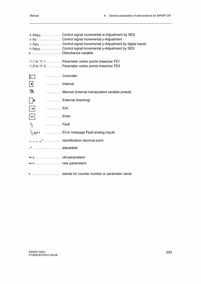
9 General explanation of abbreviations for SIPART DRManual
SIPART DR21C73000-B7476-C143-08
233
ΔwES Control signal incremental w-Adjustment by SES. . . . . . . . . . .Δy Control signal incremental y-Adjustment. . . . . . . . . . . . . .ΔyDI Control signal incremental y-Adjustment by digital inputs. . . . . . . . . . . .ΔyES Control signal incremental y-Adjustment by SES. . . . . . . . . . . .z Disturbance variable. . . . . . . . . . . . . . . . .
-1.1 to 11.1 Parameter vertex points linearizer FE1. . . . . . . .-1.3 to 11.3 Parameter vertex points linearizer FE3. . . . . . . .
Controller. . . . . . . . .
Internal. . . . . . . . .
Manual (internal manipulated variable preset). . . . . . . . .
External (tracking). . . . . . . . .
Exit. . . . . . . . .
Enter. . . . . . . . .
Fault. . . . . . . . .
Error message Fault analog inputs. . . . . . . . .
Identification decimal point. . . . . . . . .
AI**
↗ adjustable. . . . . . . . . . . . . . . .
**.o old parameters. . . . . . . . . . . . . . .
**.n new parameters. . . . . . . . . . . . . . .
* stands for counter number or parameter name. . . . . . . . . . . . . . . . .

9 General explanation of abbreviations for SIPART DR Manual
234 SIPART DR21C73000-B7476-C143-08
Manual
SIPART DR21C73000-B7476-C143-07
235
Index
Numbers
6DR210x--4, Connection, 1306DR210x--5, Connection, 1306DR2800--8J
Connection, 133Connection example, 137Function principle of the option module, 28Technical Data, 40
6DR2800--8RConnection, 134Function principle of the option modules, 28Technical Data, 40
6DR2800--8VConnection, 135Function principle of the option modules, 29Technical Data, 41
6DR2801--8C, 142Function principle of the option modules, 31Technical Data, 43
6DR2801--8D, 143Function principle of the option modules, 30Technical Data, 42
6DR2801--8E, 142Function principle of the option modules, 30Technical Data, 43
6DR2803--8C, 144Function principle of the option modules, 32Technical Data, 44
6DR2803--8P, 146Connection, 147Function principle of the option modules, 31Technical Data, 43
6DR2804--8A, 1436DR2804--8A/B, Technical Data, 456DR2804--8B, 1436DR2805--8A, Function principle of the optionmodules, 296DR2805--8J, 135
Function principle of the option modules, 30Technical Data, 42
A
A/D converter, Technical Data, 38A1 to A4, Digital outputs, Features, 22Actual value, 150Actual value display, Functional explanation,58Actuating time tp and tM, 94AdAP, 186
Configuration mode, 156Parameter list, 161
Adaptation, 113Aborted, 157Condition, 157Error messages, 162
Adaptive filter, 115, 185Alarm LED, 151Amplitude of the step command, 186Analog input, Universal module, 135Analog inputs
Features, 19Functional principle of the standard control-ler, 26Technical Data, 36
Analog output signal processing (S56), 110Analog outputs, Technical Data, 37AO, Connection, 131Application examples, 193APSt, 178
Configuring, 27Automatic mode, Controller output structure,107
B
Backplane moduleRemoval, 121Replacing, 225
Backplane module with power supply unit, De-sign, 24bLb
Digital outputs, Features, 21Functional explanation, 54Operating locks, 149

Manual
236 SIPART DR21C73000-B7476-C143-07
Block diagram, 129bLPS
Digital outputs, Features, 21Functional explanation, 54Operating locks, 149
bLSDigital outputs, Features, 21Functional explanation, 54
bLS, Operating locks, 149
C
CAE3, Set UNI--module, 173Cascade controls, 63CB
Digital outputs, Features, 21Functional explanation, 54
Changing the scales, 123Changing the tag plate, 123Commissioning, 181Configuration examples, 199Configuration mode, 149, 154
AdAP (adaptation), 156oFPA (offline parameters), 163onPA (online parameters), 155StrS (structure switch), 165
Configuring, Functional principle of the stan-dard controller, 27Configuring the controller, Application exam-ples, 193Configuring tool, 216
for structuring, 221to oFPA, 219to onPA, 218
Connecting elements, Arrangement, 126Connection
6DR210x--4, 1306DR210x--5, 1306DR2800--8J, 1336DR2800--8R, 1346DR2800--8V, 135AO, 131Options modules, 133DI1 to DI2, 131DO1 to DO2, 132Electrical, 126Examples, 137
Ground, 128Interface module, 144Measuring lines, 127, 130PE conductor, 126Power Supply, 126, 130PROFIBUS--DP, 147RS 232, 144Signal lines, 127, 130Standard controller, 130
Connection technique, Design, 25Constants c1 to c7, Functional explanation, 57Control algorithm, 91Control parameters
automatic setting, 186Setting by the adaptation method, 189
Control signalsfor setpoint switching, 63Functional explanation, 54, 57
Display range, Functional explanation, 58Control system coupling, 89, 90
via serial interface, 109Control unit, 80, 83
DDC fixed setpoint controller, 69Controlled ratio controller, 75Controlled system with compensation, Trans-ient function, 191Controlled variable processing, 64Controller, installing, 124Controller design, Adaptation, 114Controller direction of control action, Adapta-tion to controlled system, 181Controller direction of effect, 91Controller output structure
S2=0, 94S2=1, 95S2=2, 99S2=3, 102
Controller output structures, 94Controller types, 55Controls
SPC, 63Cascade, 63Synchronized, 63
Coupling relay, Technical Data, 45
Manual
SIPART DR21C73000-B7476-C143-07
237
CPUFunctional principle of the standard control-ler, 26self--diagnostics, 179
D
DDC fixed setpoint controller, 68Control unit, 69
Design, 24DI1 to DI2, Connection, 131Digital inputs
Assignment and direction of effect, 50Features, 21, 22Functional principle of the standard control-ler, 26Linking with the control signals, 50Technical Data, 37
Digital output signal processing (S57 to S75),111Digital outputs
FeaturesA1 to A4, 22bLb, 21bLPS, 21bLS, 21CB, 21H, 22He, 21MUF, 22N, 21Nw, 22P, 21RB, 22RC, 22Si, 21tS, 21tSH, 21w, 22y, 22yBL, 21
Functional principle of the standard control-ler, 26Technical Data, 38
Direction of control action, 181of actuator, 181of system, 181
Direction of effectactuator, 182system, 182
Direction--dependent blocking operation, 108Display, software version, 151Display levels, 73Display technique, Technical Data, 39DO1 to DO2, Connection, 132dy -- amplitude of the step command, Preset-ting, 186
E
Error messages, Adaptation, 162Explanation of abbreviations, 229external setpoint wE, 64
F
Factory setting, 178Behavior of the controller, 150
Features, 19Filter, Setting, 185Fixed setpoint controller
DDC, 68with 2 independent setpoints, 59with one setpoint (control system coupling),89
Front moduleDesign, 24Replacing, 224
Function principle, 26Functional description
Controller types, 55Structure switches, 47
Functional explanation, of the digital messagesignals, 111Fundamental control technology terms, 9
Actuators, 9Controller output signal, 12Continuous controller, 13Control loop, 9control response, 10Three--position step controller with internalfeedback, 12Final control elements, 9P controller, 10PD controller, 11PI controller, 11PID controller, 11
Manual
238 SIPART DR21C73000-B7476-C143-07
Sensor, 9Step function, 10transmitter, 9Two--position controller, 14
H
H, Digital outputs, Features, 22He
Digital outputs, Features, 21Functional explanation, 54
I
I/U module, Function principle of the optionmodules, 28Installation, 121
Selecting the Installation Site, 121Internet address:, 31
K
K controllerDirection of effect, 181Setting the floating time, 183
Kp, 187
L
Lamp test, 151Limit value alarms, 117Line capacitance, Technical Data, 44Linearizer, 118
M
Maintenance, 223Manipulated variable, 150Manipulated variable adjustment, TechnicalData, 38Manipulated variable limit, 93Manual control station, 85Manual mode, 107
absolute ~, 154Measuring inputs, Modules, 133Measuring range
I, 175mV, 175
Pt100, 176Resistance potentiometer, 177Thermocouples, 175U, 175
Measuring range plugFunction principle of the option modules, 30Pin assignment, 135Technical Data, 42
Measuring transmitter feed, Technical Data, 38Mechanical Installation, 121Modules
for analog measuring inputs, 133for expanding the digital inputs, 142for expanding the digital outputs, 142
Monitoring time tU, Presetting, 186MUF, Digital outputs, Features, 22mV transmitter, Pin assignment, 135
N
NDigital outputs, Features, 21Functional explanation, 54
Tracking N, Functional explanation, 56Nw, Digital outputs, Features, 22
O
Offline mode, 154Parameter list, 164
oFPAConfiguration mode, 163Configuring, 27Configuring tool, 219
Online mode, 154Parameter list, 155
onPAConfiguration mode, 155Configuring, 27Configuring tool, 218
Operating locks, 149bLb, 149bLPS, 149bLS, 149
Operating pointautomatic, 93fixed, 93
Manual
SIPART DR21C73000-B7476-C143-07
239
y0 in P--controller, 93Operation, 149Operation mode
Configuration mode, 149Process operation mode, 149Selection level, 149
Operation with 2 or 3 setpoints, 64Option module, Function principle, 28Options modules
Connection, 133Installation, 125Replacing, 225
Ordering data, 228Output signal processing
analog, 110digital, 111
Output structure, Features, 19Outputs for the manipulated variable Y, Func-tional principle of the standard controller, 26
P
PDigital outputs, Features, 21Functional explanation, 54
P--controller, 91Setting, 189
Parameter listAdAP, 161oFPA (offline parameters), 164onPA (online parameters), 155
parameters, Technical Data, 39PD--controller, Setting, 189PI--controller, 91PI--controller, Setting, 190PID controller, Setting, 190Pin assignment
Measuring range plug, 135mV transmitter, 135Pt100 sensor, 136Resistance potentiometer, 137Thermocouples, 136
Power Supply, Standard controller, 36Power supply unit
Features, 20
Functional principle of the standard control-ler, 27
PresettingAmplitude of the step command dy, 186Direction of step command Pv, 186Monitoring time tU, 186
Process display, 80Process operation mode, 149, 150PROFIBUS DP, 120
Technical Data, 43PROFIBUS--DP, 146
Connection, 147Structure switches, 173
PT100, Measuring range, 176Pt100 sensor, Pin assignment, 136Pv -- Direction of step command, Presetting,186
R
R, 137R module, Function principle of the option mo-dules, 28Range of Application, 18Ratio controller
controlled, 75Example, 78
RB, Digital outputs, Features, 22RC, Digital outputs, Features, 22Rear of controller, 121reference point, Function principle of the optionmodules, 29Relay contacts, unlock, 122Replacing
Backplane module, 225Front module, 224Options modules, 225
Resistance potentiometerMeasuring range, 177Pin assignment, 137
Resistor input, 134Response threshold, Setting, 185Response threshold AH, 116Restart conditions, 120

Manual
240 SIPART DR21C73000-B7476-C143-07
RS 485, 145RTD, 136
S
S controllerAdaptation to the actuating drive, 183Direction of effect, 182
S--output, Technical Data, 37S2=0, Controller output structure, 94S2=1, Controller output structure, 95S2=2, Controller output structure, 99S2=3, Controller output structure, 102SA, Functional explanation, 56Safety notes, 17Safety operation, 107Scope of delivery, 17SE, Functional explanation, 56Selecting the control behavior, 186Selection level, 149Selection mode, 152Serial interface, 120
Control system coupling, 109Features, 22PROFIBUS--DP, Function principle of theoption modules, 31RS 232/RS 485, Function principle of theoption modules, 32Technical Data, 44
Setpoint, 150Setpoint change tSH, Functional explanation,54Setpoint display, Functional explanation, 58Setpoint limits SA and SE, Functional explana-tion, 56Setpoint potentiometer, 83Setpoint ramp tS
Functional description, 55Functional explanation, 54
Setpoints, 195Setting
P--controller, 189PD--controller, 189PI--controller, 190PID controller, 190the control parameters automatically, 186
the control parameters manually, 189, 191Si
Digital outputs, Features, 21Functional explanation, 54
Slave controller, 62without Int/Ext switching, 90
software version, Display, 151Spare parts list, 227SPC controls, 63SPC--controller, 62Standard controller
Connection, 130Design, 24Function principle, 26Other functions, 115Power Supply, 36
Start parameters, 161Step command, Presetting, 186StrS
Configuration mode, 165Configuring, 27Structure switches, 166
Stru, Configuring tool, 221Structure switch list, 166Structure switches
Analog input signal processing, 47Configuring tool, 221Digital input signal processing, 50Functional description, 47
SwitchingP--PI, 94to automatic mode, 94
Switching over to manual operation, 47, 108Synchronized controller, 62Synchronized controls, 63System identification, Adaptation, 113
T
TC, 136Technical Data, 34Technical Description, 17Thermocouples
Measuring range, 175Pin assignment, 136
Tracking operation, 107

Manual
SIPART DR21C73000-B7476-C143-07
241
Transient function, of a controlled system withcompensation, 191Transmitter fault, Switching over to manualoperation, 47, 108tS
Digital outputs, Features, 21Functional description, 55Functional explanation, 54
tSHDigital outputs, Features, 21Functional explanation, 54
tU (monitoring time), Presetting, 186
U
UNI module:Function principle of the option modules, 29Technical Data, 41
Universal module for analog input, 135
V
Voltage output, Features, 20
W
w, Digital outputs, Features, 22
wE, 64wi
Functional description, 55Manual setpoint setting, 55
Work prior to installation, 121Working with different setpoints, 195wvi, Nominal ratio setting, 55
X
x--tracking (S43), Functional explanation, 56
Y
y, Digital outputs, Features, 22y display, 59, 98
Source and direction of effect, 108yBL
Digital outputs, Features, 21Functional explanation, 54
Z
zD, 91zy, 91

Manual
242 SIPART DR21C73000-B7476-C143-07