Chassis Design using Composite Materials – MBS … · Chassis Design using Composite Materials ...

© 2016 MITSUBISHI HEAVY INDUSTRIES, LTD. All Rights Reserved. SIP-IMASM 2016
Development of Composite Materials for Aircraft Structures
SIP-IMASM 2016
AIST Tsukuba Center, Japan 27, Sept. 2016
Kiyoka Takagi Mitsubishi Heavy Industries, Ltd.
Integrated Defense & Space Systems Koichi Hasegawa
Mitsubishi Heavy Industries, Ltd. Research & Innovation Center

© 2016 MITSUBISHI HEAVY INDUSTRIES, LTD. All Rights Reserved.
SIP – IMASM 2016
Outline
1
This work was supported by Council for Science, Technology and Innovation (CSTI), Cross-ministerial Strategic Innovation Promotion Program (SIP), “Structural Materials for Innovation” (Funding agency: JST).
Feature of Carbon Fiber Reinforced Plastic (CFRP)
CFRP Application in Aircraft
Static Strength of CFRP
Damage Tolerance of CFRP
Inter-layer Damage Growth Mechanisms
Improving Damage Growth Resistance
Introduction of SIP unit A11

© 2016 MITSUBISHI HEAVY INDUSTRIES, LTD. All Rights Reserved.
SIP – IMASM 2016
Strength of Fiber Reinforced Plastic
2
CFRP(HT): Carbon Fiber Reinforced Plastic
(High Tension Strength Type)
CFRP(HM):Carbon Fiber Reinforced Plastic
(High Modulus Type)
AFRP: Aramid Fiber Reinforced Plastic
GFRP:Glass Fiber Reinforced Plastic
BFRP:Boron Fiber Reinforced Plastic
SiC(CVD):Silicon Carbide Fiber
(Chemical Vapor Deposition)
LAS:Lithium Alumino-Silicate Glass
(Ref. 日本複合材学会Home Page)
Specific Modulus
Spe
cific
Stre
ngth
Fiber Reinforced Plastic
Metal Fiber
Reinforced Metal
Pitch
Pitch
CFRP is high specific strength and high specific modulus
Ref: MICHAEL・C・Y・NIU 「COMPOSITE AIRFRAME STRUCTURES」
FIBER RESIN
© 2016 MITSUBISHI HEAVY INDUSTRIES, LTD. All Rights Reserved.
SIP – IMASM 2016
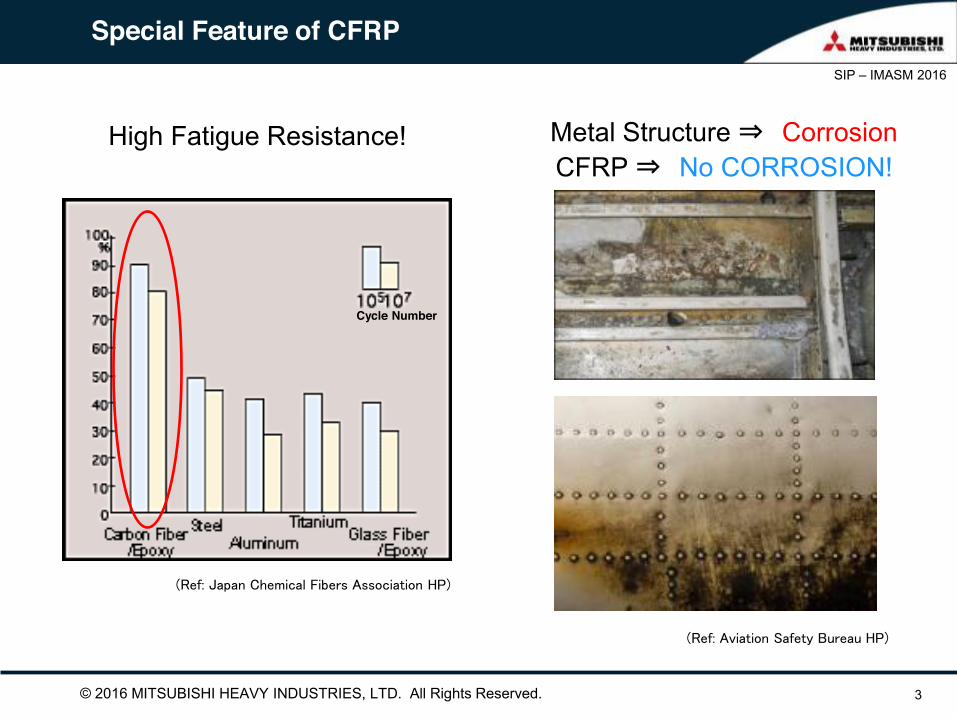
Special Feature of CFRP
3
High Fatigue Resistance!
(Ref: Japan Chemical Fibers Association HP)
Cycle Number
(Ref: Aviation Safety Bureau HP)
Metal Structure ⇒ Corrosion CFRP ⇒ No CORROSION!

© 2016 MITSUBISHI HEAVY INDUSTRIES, LTD. All Rights Reserved.
SIP – IMASM 2016
Out-of-Plane Strength of CFRP
4
Out-of-Plane strength is 1/10 of in-Plane
EXTREMELY WEAK
Ftu
Ftu
1/10×Ftu
The Cause of Problem on Composite Material Structure is Almost Due to Out-of-Plane Force and Weakness
High Out-of-Plane Strength CFRP is Desired Interlaminar Tension Failure
Induced Interlaminar Tension Failure Under compression
Interlaminar Tension Failure
Induced Interlaminar Tension Failure Under compression
Various Interlaminar (Flatwise) Tension Failures
Peal Stress Figure of Spar Structure
Peak Stress
Skin
Spar
Michael C.Y. Niu, Composite Airframe Structure, ISBN 978-962-7128-11-3
© 2016 MITSUBISHI HEAVY INDUSTRIES, LTD. All Rights Reserved.
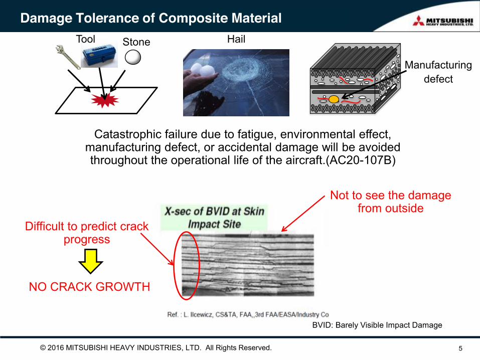
Damage Tolerance of Composite Material
5
Catastrophic failure due to fatigue, environmental effect, manufacturing defect, or accidental damage will be avoided throughout the operational life of the aircraft.(AC20-107B)
BVID: Barely Visible Impact Damage
Tool Stone Hail
Manufacturing defect
Not to see the damage from outside
Difficult to predict crack progress
NO CRACK GROWTH

© 2016 MITSUBISHI HEAVY INDUSTRIES, LTD. All Rights Reserved.
SIP – IMASM 2016
6
Delamination or inter-layer crack is the most critical to strength
Smaller damage tend to work as precursor of delamination
Damage Type and Criticality
http://ams.me.kyoto-u.ac.jp/research2006/tf.htm
(Noh et al., 2003)
Fiber/matrix debond Matrix Crack Delamination
• No harm to strength at this stage
Link-up Create
• No great harm to strength at this stage
• Slight stiffness reduction
• Cause significant strength reduction especially in compression and out-of-plane loading
(Bull, 2014)
1 μm 100 mm 100 μm

© 2016 MITSUBISHI HEAVY INDUSTRIES, LTD. All Rights Reserved.
SIP – IMASM 2016
7
Need more detailed observation of damage in micro scale • Complicated propagating behavior due to the heterogeneity and various constituents
involved
• Damage hard to visually recognize until the last minute unlike metals
Damage modeling to follow the observation • To clarify which mechanism makes the most significant contribution to the growth
• To aid selection of material constituents leading to superior damage growth resistance while reducing try-and-error
Inter-layer Damage Growth Mechanisms

© 2016 MITSUBISHI HEAVY INDUSTRIES, LTD. All Rights Reserved.
SIP – IMASM 2016
Inter-layer Damage Growth Mechanisms
8
Damage observation utilizing X-ray computed tomography (CT) • Powerful for identifying internal micro and macro damage in 3D compared to
conventional techniques
• Combination of a lab CT and synchrotron CT proved to be effective
• In-situ observation of damage growth possible by incorporating a loading unit
(Garcea et al., 2014)
(Shen et al., 2012)
© 2016 MITSUBISHI HEAVY INDUSTRIES, LTD. All Rights Reserved.
SIP – IMASM 2016
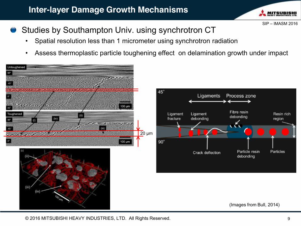
Inter-layer Damage Growth Mechanisms
9
Studies by Southampton Univ. using synchrotron CT • Spatial resolution less than 1 micrometer using synchrotron radiation
• Assess thermoplastic particle toughening effect on delamination growth under impact
(Images from Bull, 2014)
20 μm
© 2016 MITSUBISHI HEAVY INDUSTRIES, LTD. All Rights Reserved.
SIP – IMASM 2016
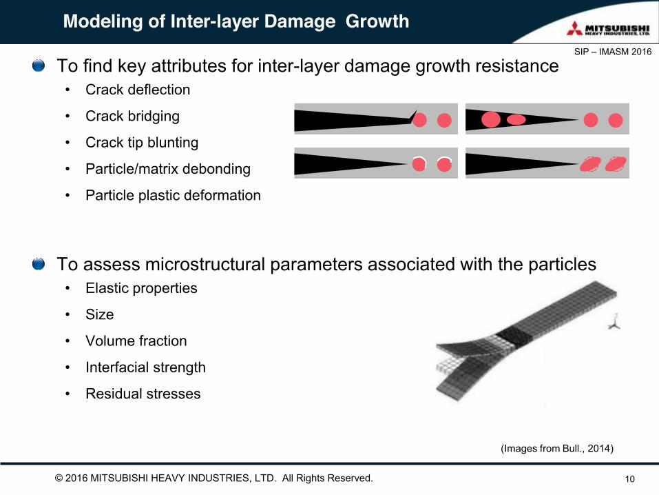
Modeling of Inter-layer Damage Growth
10
To find key attributes for inter-layer damage growth resistance • Crack deflection
• Crack bridging
• Crack tip blunting
• Particle/matrix debonding
• Particle plastic deformation
(Images from Bull., 2014)
To assess microstructural parameters associated with the particles • Elastic properties
• Size
• Volume fraction
• Interfacial strength
• Residual stresses
© 2016 MITSUBISHI HEAVY INDUSTRIES, LTD. All Rights Reserved.
SIP – IMASM 2016
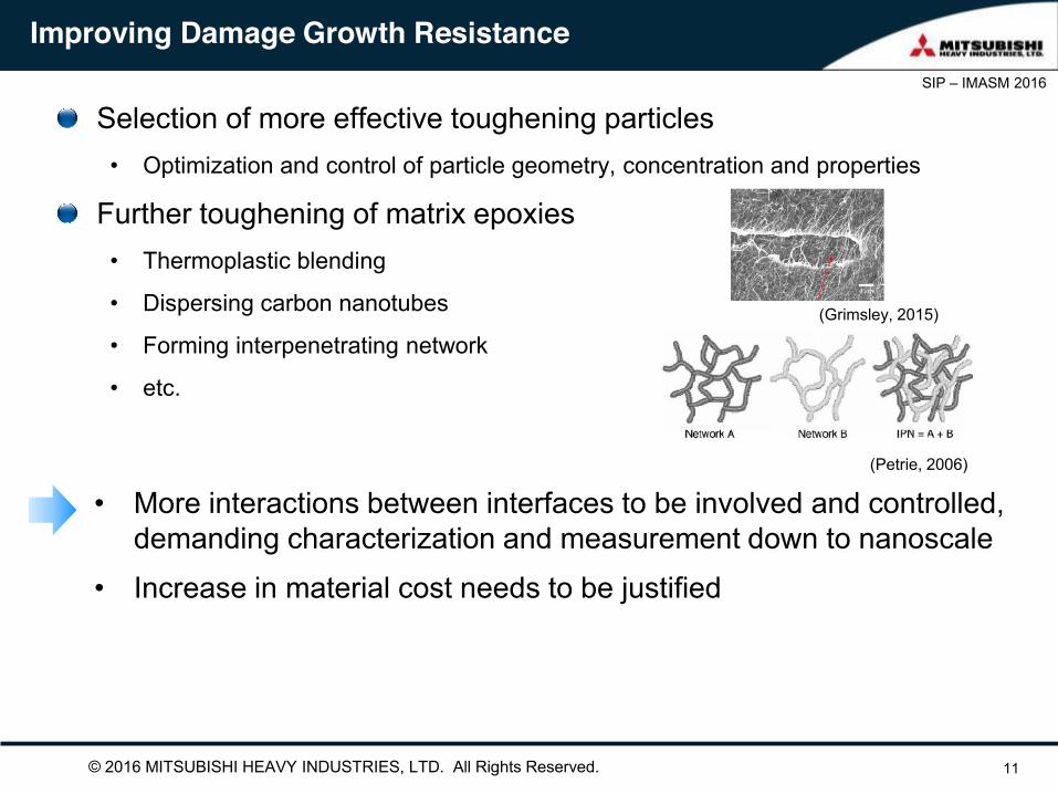
Improving Damage Growth Resistance
11
Selection of more effective toughening particles • Optimization and control of particle geometry, concentration and properties
Further toughening of matrix epoxies • Thermoplastic blending
• Dispersing carbon nanotubes
• Forming interpenetrating network
• etc.
• More interactions between interfaces to be involved and controlled, demanding characterization and measurement down to nanoscale
• Increase in material cost needs to be justified
(Petrie, 2006)
(Grimsley, 2015)

© 2016 MITSUBISHI HEAVY INDUSTRIES, LTD. All Rights Reserved.
SIP – IMASM 2016
12
Interface between carbon fiber and matrix epoxy • Primary (covalent) bond or secondary bond?
• Work by BMW to indirectly prove the presence of covalent bond via sizing agent
?
+
160 C
(Wetjen et al., 2015)
Nanoscale Characterization: Example
OH O
Fiber surface activation and Sizing Solvent wash Detect sizing remained on the fiber
Carbon fiber Sizing
R R’
Epoxy 1 Epoxy 2
© 2016 MITSUBISHI HEAVY INDUSTRIES, LTD. All Rights Reserved.
SIP – IMASM 2016
13
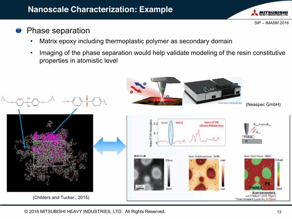
Phase separation • Matrix epoxy including thermoplastic polymer as secondary domain
• Imaging of the phase separation would help validate modeling of the resin constitutive properties in atomistic level
(Childers and Tucker., 2015)
(Neaspec GmbH)
Nanoscale Characterization: Example
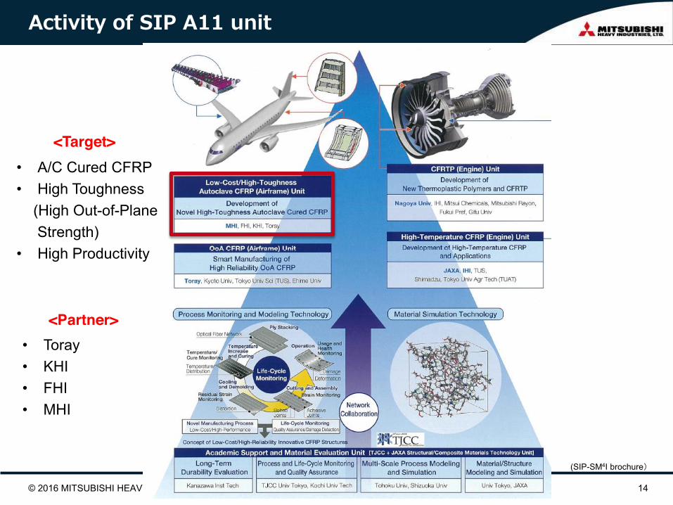
Activity of SIP A11 unit
© 2016 MITSUBISHI HEAVY INDUSTRIES, LTD. All Rights Reserved. 14
• A/C Cured CFRP • High Toughness (High Out-of-Plane Strength) • High Productivity
(SIP-SM4I brochure)
<Target>
<Partner> • Toray • KHI • FHI • MHI

© 2016 MITSUBISHI HEAVY INDUSTRIES, LTD. All Rights Reserved.
SIP – IMASM 2016
Summary
15
Application of composites to aircraft structures has been expanded over the last decades and forecasted to grow owing to their superior strength and durability One of the keys to promote the application to aircraft is to improve resistance to inter-layer damage growth and thereby out-of-plane strength for ensuring weight advantage over current metallic structures Microstructure of composites make the damage growth behavior rather complicated; More accurate observation and understanding of internal microscopic damage is the first step for further improvement of those performances
Combining the observation with a modeling method to assess the most contributing micro-mechanisms, further improvement of CFRP performance is expected
Nanoscale characterization of interfacial properties should be more focused to quantify both physical and chemical interaction
© 2016 MITSUBISHI HEAVY INDUSTRIES, LTD. All Rights Reserved.
SIP – IMASM 2016
16
Thank you for your attention !
This work was supported by Council for Science, Technology and Innovation (CSTI), Cross-ministerial Strategic Innovation Promotion
Program (SIP), “Structural Materials for Innovation” (Funding agency: JST).
Acknowledgments