SINAMICS S110 EPOS via FB283 - Siemens
78
Applications & Tools Answers for industry. Cover sheet SINAMICS S110 EPOS via FB283 Control via PROFINET – Safety via F-DI Application Description February 2012
Transcript of SINAMICS S110 EPOS via FB283 - Siemens

Applications & Tools
Answers for industry.
Cover sheet
SINAMICS S110
EPOS via FB283
Control via PROFINET – Safety via F-DI
Application Description February 2012

2 SINAMICS S110 - EPOS über FB283
1.0, Article ID: 58703073
Co
pyr
igh
t
Sie
me
ns
AG
20
12
All
righ
ts r
ese
rve
d
Siemens Industry Online Support
This article is taken from the Siemens Industry Online Support. The following link takes you directly to the download page of this document:
http://support.automation.siemens.com/WW/view/en/58703073
Caution The functions and solutions described in this article confine themselves to the realization of the automation task predominantly. Please take into account furthermore that corresponding protective measures have to be taken up in the context of Industrial Security when connecting your equipment to other parts of the plant, the enterprise network or the Internet. Further information can be found under the Item-ID 50203404.
http://support.automation.siemens.com/WW/view/en/50203404
If you have any questions concerning this document please e-mail us to the following address:
You can also actively use our Technical Forum from the Siemens Industry Online Support regarding this subject. Add your questions, suggestions and problems and discuss them together in our strong forum community:
http://www.siemens.com/forum-applications

Warranty and liability
SINAMICS S110 - EPOS über FB283 1.0, Article ID: 58703073 3
Co
pyr
igh
t
Sie
me
ns
AG
20
12
All
righ
ts r
ese
rve
d
FE
_F
B28
3_P
rofin
et_
en.d
oc
Warranty and liability Note The application examples are not binding and do not claim to be complete
regarding the configuration and equipping as well as possible eventualities. The application examples do not represent customer-specific solutions. They are only intended to provide support for typical applications. You are responsible in ensuring that the described products are correctly used. These application examples do not relieve you of the responsibility of safely and professionally using, installing, operating and servicing equipment. When using these application examples, you recognize that we cannot be made liable for any damage/claims beyond the liability clause described. We reserve the right to make changes to these application examples at any time without prior notice. If there are any deviations between the recommendations provided in this application example and other Siemens publications - e.g. Catalogs, then the contents of the other documents have priority.
We do not accept any liability for the information contained in this document.
Claims against us – irrespective of the legal grounds – resulting from the use of the examples described in this application example, information, programs, engineering and performance data etc. are excluded. Such an exclusion shall not apply where liability is mandatory, e.g. under the German Product Liability Act involving intent, gross negligence, or injury of life, body or health, guarantee for the quality of a product, fraudulent concealment of a deficiency or non-performance. Claims of the purchaser for compensation relating to non-performance of essential contract obligations shall be limited to foreseeable damages typically covered by a contract unless intent, willful misconduct or gross negligence is involved or injury of life, body or health. The above stipulations shall not change the burden of proof to your detriment.
It is not permissible to transfer or copy these application examples or excerpts of them without first having prior authorization from Siemens Industry Sector in writing.

Table of Contents
4 SINAMICS S110 - EPOS über FB283
1.0, Article ID: 58703073
Co
pyr
igh
t
Sie
me
ns
AG
20
12
All
righ
ts r
ese
rve
d
Table of Contents Warranty and liability................................................................................................... 3 1 Automation function.......................................................................................... 6
1.1 Description of the functionality ............................................................. 6 2 Functionality of the function example............................................................. 7
2.1 Task description ................................................................................... 7 2.2 Solution ................................................................................................ 7 2.3 Structure of the function example ........................................................ 7
3 Components required ....................................................................................... 8 3.1 Hardware components ......................................................................... 8 3.2 Software components........................................................................... 9
4 Structure and wiring........................................................................................ 10 4.1 Connecting-up the hardware components ......................................... 11 4.1.1 Connecting up S7-300 and S110 for PROFINET .............................. 11 4.1.2 F-DI for Safety via terminal ................................................................ 12 4.1.3 PM340 with motor .............................................................................. 12
5 Download.......................................................................................................... 13 5.1 S7 program......................................................................................... 13 5.2 Setting the SINAMICS S110 IP address and device name ............... 13 5.3 SINAMICS S110 configuration........................................................... 18 5.4 Exiting the STARTER parameterizing software ................................. 20
6 Using the application ...................................................................................... 21 6.1 Via digital inputs (additional 16xDI is required).................................. 21 6.1.1 Preparation......................................................................................... 21 6.1.2 Operator control ................................................................................. 21 6.1.3 Example ............................................................................................. 22 6.2 Variables table.................................................................................... 22 6.2.1 Reference – controlling the referencing operating mode................... 22 6.2.2 MDI – control of the direct setpoint input............................................ 24 6.2.3 TVB – controlling traversing blocks.................................................... 26 6.2.4 Acyclic tasks....................................................................................... 28 6.2.5 Parameters – read/write parameters.................................................. 29 6.2.6 Para_1_10- read/write 1-10 parameters ............................................ 30 6.2.7 TVBsingle – changing/reading out a traversing block........................ 32 6.2.8 TVBblock – changing/reading out a traversing block......................... 35 6.2.9 FaultBuffer – Read-out fault memory ................................................. 37 6.3 Function test of the safety functions................................................... 39
7 More detailed information............................................................................... 40 7.1 Configuration of a control ................................................................... 40 7.1.1 Settings in the hardware configuration............................................... 40 7.1.2 S7 program......................................................................................... 43
Call FB283.......................................................................................... 43 7.2 Configuring the SINAMICS S110 ....................................................... 45 7.2.1 SIMATIC Manager, inserting the SINAMICS S110............................ 45 7.2.2 Calling the STARTER parameterizing tool......................................... 46 7.2.3 STARTER, performing quick commissioning..................................... 47 7.2.4 STARTER, performing motor identification........................................ 49 7.2.5 Basic Safety settings via F_DI ........................................................... 51 7.2.6 Overview and settings of the position controller screen forms........... 53
Mechanics .......................................................................................... 54

Table of Contents
SINAMICS S110 - EPOS über FB283 1.0, Article ID: 58703073 5
Co
pyr
igh
t
Sie
me
ns
AG
20
12
All
righ
ts r
ese
rve
d
Position actual value preparation ....................................................... 55 Position controller............................................................................... 56 Monitoring........................................................................................... 58
7.2.7 Overview and settings of the basic positioning screen forms ............ 60 Limitation ............................................................................................ 61 Jogging 64 Homing 67 Traversing blocks ............................................................................... 70 Direct setpoint input MDI .................................................................... 72
7.2.8 Completing commissioning ................................................................ 73 7.3 FB283 error messages....................................................................... 74 7.3.1 single.ErrorNumbr .............................................................................. 74 7.3.2 SINAMICS S110................................................................................. 76 7.4 FAQ on FB283 ................................................................................... 77
8 References ....................................................................................................... 78 8.1 Internet links - data............................................................................. 78
9 Contact.............................................................................................................. 78 10 History............................................................................................................... 78

1 0BAutomation function
6 SINAMICS S110 - EPOS über FB283
1.0, Article ID: 58703073
Co
pyr
igh
t
Sie
me
ns
AG
20
12
All
righ
ts r
ese
rve
d
1 Automation function
1.1 Description of the functionality
The SINAMICS S110 frequency converter is a modular, single-axis drive with the basic positioning function. It comprises the function units Control Unit (CU) and Power Module (PM).
When using the CU305 PN there are two PROFINET interfaces. It is possible to exchange data between the converter and the control system via these interfaces.
The safety-relevant applications can be controlled via fail safe digital inputs (F-DI) or PROFIsafe in this function example the safety-relevant applications are controlled via F-DI.

2 1BFunctionality of the function example
SINAMICS S110 - EPOS über FB283 1.0, Article ID: 58703073 7
Co
pyr
igh
t
Sie
me
ns
AG
20
12
All
righ
ts r
ese
rve
d
2 Functionality of the function example
2.1 Task description
The SINAMICS S110 should be controlled via a fieldbus (PROFINET) from an S7-300 CPU. In this case, it should also be possible to change the traversing blocks from the control system.
Optionally, the safety functions should be used.
2.2 Solution
In this function example, function block FB 283 is used for this purpose. FB 283 controls the cyclic communication, and offers various types of non-cyclic jobs. This also includes a function to read and write traversing blocks, but also a user-friendly option of changing or reading any parameters.
User-specific data types (User Defined Types / UDTs) are used to improve the transparency and increase the flexibility by appropriately structuring large quantities of data.
If the safety functions of the S110 are to be used, then a corresponding chapter is provided in these instructions where it is described as to how the functions are set-up. You can select Safety via F-DI.
In addition, there are extended safety functions, what are known as motion monitoring functions. These require a license and are not discussed in this example.
2.3 Structure of the function example
The function example is sub-divided into various steps. First of all, the technical prerequisites for use are shown and how the components are connected up.
Commissioning and operation then follow, which are shown using the function example provided.
For the case that you wish to create your own project, in Chapter 7, an explanation is provided as to how you can create your own program example.

3 2BComponents required
8 SINAMICS S110 - EPOS über FB283
1.0, Article ID: 58703073
Co
pyr
igh
t
Sie
me
ns
AG
20
12
All
righ
ts r
ese
rve
d
3 Components required This example is intended for the SINAMICS S110 demonstration case (order no 6AG1067-1AA18-0AA0). If instead of this, you wish to use a design with a different configuration, then you can use the following products . It can also be implemented with compatible components. To do this, it may be necessary to change the hardware configuration (HW Config) or in the STARTER parameterizing tool.
3.1 Hardware components
Table 3-1
Component Qty. MLFB/order number Note
Power supply PS307 5A
1 6ES7307-1EA00-0AA0
S7-300-CPU CPU 315-2 PN/DP
1 6ES7315-2EH13-0AB0
Memory Card e.g. MMC 512 kB
1 6ES7953-8LJ11-0AA0
Mounting rail 1 6ES7390-1AE80-0AA0
PROFINET RJ45 connector
2 6GK1901-1BB10-2AA0
PROFINET cable 2 m 6XV1840-2AH10
SINAMICS S110 CU CU305 PN – FW 4.4
1
SINAMICS S110 PM PM340
1 6SL3210-1SB12-3AA0
Motor Synchronous servomotor
1 1FK7022-5AK71-1DA0 For Safety, a sin/cos encoder is required for synchronous motors

3 2BComponents required
SINAMICS S110 - EPOS über FB283 1.0, Article ID: 58703073 9
Co
pyr
igh
t
Sie
me
ns
AG
20
12
All
righ
ts r
ese
rve
d
3.2 Software components
Table 3-2
Component Qty. MLFB/Order No. Note
STARTER V4.2 commissioning tool
1 6SL3072-0AA00-0AG0 Or download from http://support.automation.siemens.com/WW/view/de/26233208
STEP 7 V5.5 1 6ES7822-1AA01-0YA5 Alternatively: 5.4 SP5
Distributed Safety V5.4
1 6ES7833-1FC02-0YA5 min. 5.4 SP5
Example files and projects
The following list includes all files and projects that are used in this example.
Table 3-3
Component Note
S110STD.zip <This zip file includes the STEP 7 project.>
S110STD.pdf This document.
.... ....

4 3BStructure and wiring
10 SINAMICS S110 - EPOS über FB283
1.0, Article ID: 58703073
Co
pyr
igh
t
Sie
me
ns
AG
20
12
All
righ
ts r
ese
rve
d
4 Structure and wiring The chapter describes the hardware design and how to connect up the function example.
Carefully observe the subsequent safety notes regarding the use of SINAMICS S110:
WARNING
The SINAMICS S110 has components at hazardous voltage levels and controls rotating mechanical equipment, which is also hazardous. If this warning is not carefully observed, or if the notes provided in the various SINAMICS S110 instructions are not followed, then this can result in death, severe bodily injury or significant material damage.

4 3BStructure and wiring
SINAMICS S110 - EPOS über FB283 1.0, Article ID: 58703073 11
Co
pyr
igh
t
Sie
me
ns
AG
20
12
All
righ
ts r
ese
rve
d
4.1 Connecting-up the hardware components
4.1.1 Connecting up S7-300 and S110 for PROFINET
Fig. 4-1

4 3BStructure and wiring
12 SINAMICS S110 - EPOS über FB283
1.0, Article ID: 58703073
Co
pyr
igh
t
Sie
me
ns
AG
20
12
All
righ
ts r
ese
rve
d
4.1.2 F-DI for Safety via terminal
Fig. 4-2
4.1.3 PM340 with motor
Fig. 4-3

5 4BDownload
SINAMICS S110 - EPOS über FB283 1.0, Article ID: 58703073 13
Co
pyr
igh
t
Sie
me
ns
AG
20
12
All
righ
ts r
ese
rve
d
5 Download
5.1 S7 program
To download the S7 program, you require a connection between the MPI interface of your PG/PC and the MPI interface of the S7-CPU.
• Start the "SIMATIC Manager".
• De-archive the function example provided.
• Open the "S110_FB283" project.
• Connect the control with your PG/PC via the MPI/PROFIBUS interface.
• Using "Options> Select PG/PC…", select the "AUTO" interface identification of the "MPI/PROFIBUS" interface. And configure the interface based on the results of the automatic identification.
• Select the configuration example “SIMATIC 300_PN”
• Open "HW Config" and download this to the control system. After the download, close "HW Config" again.
• By loading "HW Config", it is possible that the control system interfaces have changed. Therefore, check your "PG/PC interface" and if necessary, reconfigure. To set the device addresses, please observe Chapter 5.2 Setting the SINAMICS S110 IP address and device name.
• In the SIMATIC Manager, select the block folder via "CPU > S7 program > Blocks".
• Download all of the S7 program blocks into the CPU
5.2 Setting the SINAMICS S110 IP address and device name
Different than for PROFIBUS, for PROFINET the node addresses are not set per hardware, but per software. To do this, a connection is required between the PG/PC and the PROFINET interface of the SINAMICS S110 via TCP/IP.
• Connect the PROFINET cable from the SINAMICS S110 interface X01 P2 to the Ethernet interface of your PG/PC (see Chapter 4.1).
• Set the IP address and the subnet mask of the Ethernet card of your PG/PC as follows.

5 4BDownload
14 SINAMICS S110 - EPOS über FB283
1.0, Article ID: 58703073
Co
pyr
igh
t
Sie
me
ns
AG
20
12
All
righ
ts r
ese
rve
d
Fig. 5-1

5 4BDownload
SINAMICS S110 - EPOS über FB283 1.0, Article ID: 58703073 15
Co
pyr
igh
t
Sie
me
ns
AG
20
12
All
righ
ts r
ese
rve
d
• In STARTER via "Options > Set PG/PC interface…", select the TCP/IP interface parameterization. While working through the function example, you can execute all of the additional steps via this interface.
Fig. 5-2
• Then, in STARTER via "Target system > Edit Ethernet node…" open the "Edit Ethernet node" dialog.

5 4BDownload
16 SINAMICS S110 - EPOS über FB283
1.0, Article ID: 58703073
Co
pyr
igh
t
Sie
me
ns
AG
20
12
All
righ
ts r
ese
rve
d
• Press the "Browse…" button
Fig. 5-3
• In the dialog that is then displayed, select the SINAMICS device type nodes and press the "OK" button.
Fig. 5-4
• (1.) Now, under "IP address": enter 192.168.0.2“ and under "Subnet mask:
255.255.255.0". (2.) Then press the "Assign IP Configuration" button.

5 4BDownload
SINAMICS S110 - EPOS über FB283 1.0, Article ID: 58703073 17
Co
pyr
igh
t
Sie
me
ns
AG
20
12
All
righ
ts r
ese
rve
d
Fig. 5-5
• (3.) After completing the IP configuration assignment, enter the device names assigned in HW Config, under "Device name:" (in this function example, "S110"). (4.) By pressing the "Assign Name", this is then assigned to the SINAMICS S110.
• Close the screen form by pressing the "Close" button.

5 4BDownload
18 SINAMICS S110 - EPOS über FB283
1.0, Article ID: 58703073
Co
pyr
igh
t
Sie
me
ns
AG
20
12
All
righ
ts r
ese
rve
d
5.3 SINAMICS S110 configuration
Then download the SINAMICS S110 configuration using the STARTER commissioning tool.
• Starting from the main path of the SIMATIC Manager, start the commissioning tool STARTER by selecting the "SINAMICS_S110" icon and double clicking on the "Commissioning" icon.
Fig. 5-6
• If you have components that deviate from Chapter 3.1, then in the configuration screen form, select "Configure DDS" and follow the Wizard. In so doing, you change the motor and power unit data. (For DRIVE-CLiQ motors, the checkmark "Read out motor again" should be activated)
• In the project navigator of the STARTER commissioning tool, then select object
"S110" (1.) and press the button (2.) to establish the online connection to the frequency converter.
Fig. 5-7
• After the online connection has been established, to download the SINAMICS
S110 drive parameters, select the button .

5 4BDownload
SINAMICS S110 - EPOS über FB283 1.0, Article ID: 58703073 19
Co
pyr
igh
t
Sie
me
ns
AG
20
12
All
righ
ts r
ese
rve
d
It is not necessary to separately activate Safety, as the checksums are not checked at download. For details, see chapter 7.2.5.
• To activate the Safety functions, you must first go to Change settings in the Safety screen form. (2.)
Fig. 5-8:
• After this, you can activate the Safety functions using Copy parameters (1.) and Activate settings (2.).
• More detailed information on the topic of Safety Integrated is provided in the S110 Function Manual.
Fig. 5-9:
• In the subsequent screen forms, first output the checksums and then backup the data of the complete drive unit into the ROM.
• The drive is then ready for operation after a power on reset.

5 4BDownload
20 SINAMICS S110 - EPOS über FB283
1.0, Article ID: 58703073
Co
pyr
igh
t
Sie
me
ns
AG
20
12
All
righ
ts r
ese
rve
d
5.4 Exiting the STARTER parameterizing software
• If you do not wish to make any additional parameter settings, then you can now exit the STARTER parameterizing software.
• In the tree, select the SINAMICS S110 and transfer all parameter changes into
the ROM memory of the SINAMICS S110 by pressing the button.
• Then, transfer all of the parameters into your offline project by pressing the button.
• Disconnect the connection between the PG / PC and the SINAMICS S110 by
pressing the button.
• You can then exit STARTER via "Project > Exit" or by pressing the button.

6 5BUsing the application
SINAMICS S110 - EPOS über FB283 1.0, Article ID: 58703073 21
Co
pyr
igh
t
Sie
me
ns
AG
20
12
All
righ
ts r
ese
rve
d
6 Using the application Two options are available to use the application:
In Chapter 6.1, an S7 block is shown, which can be used in conjunction with a digital input module to control the individual functions of the S110.
How the functions are activated using different variable tables is explained in Chapter 6.2.
6.1 Via digital inputs (additional 16xDI is required)
6.1.1 Preparation
• Deviating from the target hardware, a digital input module for 16 digital inputs is required (alternatively, 2x 8xDI).
• Insert your particular module into HW Config. Ensure that the address range of the module is EW 0.
• Further, FC1 must be called in OB1. For this purpose, remove the comments for:
CALL FC 1
6.1.2 Operator control
Table 6-1
Bit
I 0.0 On/Off 1
I 0.1 Acknowledge
I 0.2 Jogging in the positive direction (jog 2)
I 0.3 Jogging in the negative direction (jog 1)
I 0.4 Start reference point approach
I 0.5 Manually set reference point (home position)
I 0.6 MDI absolute (1) or relative (0)
I 0.7 MDI continuous setpoint transfer (1) or signal edge
I 1.0 Activate MDI
I 1.1 Value transfer
I 1.2 Reject traversing task (0)
I 1.3 Intermediate stop (0)
I 1.4 Traversing block selection, bit 0
I 1.5 Traversing block selection, bit 1
I 1.6 Traversing block selection, bit 2
I 1.7 Traversing block selection, bit 3

6 5BUsing the application
22 SINAMICS S110 - EPOS über FB283
1.0, Article ID: 58703073
Co
pyr
igh
t
Sie
me
ns
AG
20
12
All
righ
ts r
ese
rve
d
(The values for MDI must be set in the control, the traversing blocks in STARTER)
6.1.3 Example
Acknowledge Deactivate continuous setpoint transfer Switch-on (edge) Traverse to the required reference point with jogging Set reference point Deactivate MDI Select traversing block 0 Reject the traversing task and set intermediate stop to 1 Activate value transfer (edge) Drive executes traversing block Set MDI to relative Activate MDI Activate value transfer (edge) Drive traverses by the specified position value Set MDI to absolute Drive traverses to the specified target position. Switching-off with Off1.
6.2 Variables table
6.2.1 Reference – controlling the referencing operating mode
A referenced drive is necessary for absolute positioning. This axis referencing can be performed using the "Reference" variable table.
Table 6-2
Variable Significance Example
DB72.DBW 172 Control word 1
DB72.DBX 173.0 p840[0] On/off1 Switch-on the drive.
0 1 Switch-on
DB72.DBX 213.3 The converter has an active fault message
DB72 DBW 230 Actual fault number
DB72.DBX 173.7 p2103.0 Acknowledge fault Faults are acknowledged for a positive edge.
DB72.DBX 172.0 p2589 EPOS jogging 1 Drive is traversed in jogging mode 1 (standard = negative traversing direction)
1 = traversing in the negative direction of rotation
DB72.DBX 172.1 p2590 EPOS jogging 2 Drive is traversed in jogging mode 2 (standard = positive traversing direction)
1 = traversing in the positive direction of rotation
DB72.DBX 172.3 Starting referencing (active/passive) 0
DB72.DBX 177.1 Manually setting the reference point 0 1 Set reference point
DB72.DBX 176.0 Selecting the referencing type 0 = reference point approach (active) 1 = flying referencing (passive)
DB72.DBX 177.2 Signal for the reference cams (Required for active referencing using the reference cams and encoder zero mark)
DB72.DBX 176.1 Homing start direction (active homing)
DB72.DBD 222 Position actual value
DB72.DBX 212.3 Feedback signal, drive referenced

6 5BUsing the application
SINAMICS S110 - EPOS über FB283 1.0, Article ID: 58703073 23
Co
pyr
igh
t
Sie
me
ns
AG
20
12
All
righ
ts r
ese
rve
d
Control example – manually setting the reference point
Switch-on the drive Traverse to the reference position, jogging Manually set the reference point. For more detailed information on referencing, see Chapter 7.2.7 Overview and settings of the basic positioning screen forms in the Referencing section.
6 5BUsing the application
24 SINAMICS S110 - EPOS über FB283
1.0, Article ID: 58703073
Co
pyr
igh
t
Sie
me
ns
AG
20
12
All
righ
ts r
ese
rve
d
6.2.2 MDI – control of the direct setpoint input
The variable table MDI is used to control the MDI operating mode, which is also called direct setpoint input.
Table 6-3
Variable Significance Example
DB72.DBW 172 Control word 1
DB72.DBX 173.0 p840[0] On/Off1 Switch-on the drive.
0 1 Switching-on
DB72.DBX 173.4 p2641 EPOS reject traversing task Must be "true" for traversing. For "false", the task is rejected.
1 Do not reject task
DB72.DBX 173.5 p2640 EPOS intermediate stop Must be "true" for traversing. For "false", the drive is stopped.
1 No intermediate stop
DB72.DBX 173.6 (p2631 activate traversing task Selected traversing task is activated. If MDI is activated (p2647 = "true"), not relevant) p2650 MDI setpoint transfer Accepts the MDI setpoint for a positive edge. (If p2649 = "false")
0 1 Accepts the MDI setpoint
DB72.DBX 213.3 The converter has an active fault message
DB72 DBW 230 Actual fault number
DB72.DBX 173.7 p2103.0 Acknowledge fault Faults are acknowledged for a positive edge.
DB72.DBX 172.0 p2589 EPOS jogging 1 Drive is traversed in jogging mode 1 (standard = negative traversing direction)
0
DB72.DBX 172.1 p2590 EPOS jogging 2 Drive is traversed in jogging mode 2 (standard = positive traversing direction)
0
DB72.DBX 174.0 p2648 MDI positioning type "true" = absolute positioning (axis must be referenced) "false" = relative positioning
0 Relative positioning

6 5BUsing the application
SINAMICS S110 - EPOS über FB283 1.0, Article ID: 58703073 25
Co
pyr
igh
t
Sie
me
ns
AG
20
12
All
righ
ts r
ese
rve
d
Variable Significance Example
DB72.DBX 174.1 p2651 MDI direction selection, positive *)
DB72.DBX 174.2 p2652 MDI direction selection, negative *)
*) EPOS direction selection when setting up: Preselection, traversing direction The axis remains stationary if both are selected or deselected. EPOS direction selection when positioning and activated modulo correction and absolute positioning: Absolute positioning in the selected direction The axis positions along the shortest path if both are selected or deselected.
DB72.DBX 174.4 p2649 EPOS MDI transfer type, selection. If "false", then the values are only transferred for a positive edge of p2650. If "true", the values are continuously transferred and relative positioning is not permissible.
0 Transfer setpoint for edge
DB72.DBX 174.6 p2653 Setting up MDI. The drive is traversed with the selected velocity and acceleration values for MDI with p2651 (positive direction) and p2652 (negative direction).
0
DB72.DBX 174.7 p2647 MDI selection With "true", positioning is activated via MDI.
1 Positioning via MDI
DB72.DBW 180 p2646 Velocity override Scaling factor for the velocity as a %.
16384 (= 100%)
DB72.DBD 182 p2642 MDI position setpoint Enter the position setpoint.
360000
DB72.DBD 186 p2643 MDI velocity setpoint Enter the velocity setpoint in LU/min.
1440000 (= 4000 rpm)
DB72.DBW 190 p2644 MDI acceleration override Scaling factor for the acceleration as a %.
16384 (= 100%)
DB72.DBW 192 p2645 MDI deceleration override Scaling factor for the deceleration as a %.
16384 (= 100%)
DB72.DBW 212 r0052 Status word 1
DB72.DBX 213.2 r0899.2 Operation enabled
DB72.DBD 222 r2521.0 Position actual value, position controller
DB72.DBD 226 r0063 Speed actual value, smoothed
Control example – relative traversing using MDI
Deselect setting up and jogging (0) Reject traversing task and deactivate intermediate stop (1) Select positioning type Select transfer type Select MDI Enter setpoints Switch-on drive Activate traversing task
For more detailed information on MDI, refer to Chapter 7.2.7 Overview and settings of the basic positioning screen forms in Section, Direct selection/MDI.

6 5BUsing the application
26 SINAMICS S110 - EPOS über FB283
1.0, Article ID: 58703073
Co
pyr
igh
t
Sie
me
ns
AG
20
12
All
righ
ts r
ese
rve
d
6.2.3 TVB – controlling traversing blocks
Traversing blocks can be controlled using the variable table TVB.
Table 6-4
Variable Significance Example
DB72.DBW 172 Control word 1
DB72.DBX 173.0 p840.0 On/off1 Switch-on the drive.
0 1 Switching-on
DB72.DBX 173.4 p2641 EPOS reject traversing task Must be "true" for traversing. For "false", the task is rejected.
1 Do not reject task
DB72.DBX 173.5 p2640 EPOS intermediate stop Must be "true" for traversing. For "false", the drive is stopped.
1 No intermediate stop
DB72.DBX 173.6 (p2631 activate traversing task Selected traversing task is activated. p2650 MDI setpoint transfer Accepts the MDI setpoint for a positive edge. (If p2649 = "false")
0 1 Activate traversing task
DB72.DBX 213.3 The converter has an active fault message
DB72 DBW 230 Actual fault number
DB72.DBX 173.7 p2103.0 Acknowledge fault Faults are acknowledged for a positive edge.
DB72.DBX 172.0 p2589 EPOS jogging 1 Drive is traversed in jogging mode 1 (standard, negative direction)
0
DB72.DBX 172.1 p2590 EPOS jogging 2 Drive is traversed in jogging mode 2 (standard, positive direction)
0
DB72.DBX 174.7 p2647 MDI selection With "false", positioning via MDI, which has priority, is deactivated.
0 Deactivate MDI
DB72.DBB 175 Traversing block number 0 Select traversing block 0
DB72.DBX 175.0 p2625 Traversing block selection, bit 0 Weighting: 20 = 1
DB72.DBX 175.1 p2626 Traversing block selection, bit 1 Weighting: 21 = 2
DB72.DBX 175.2 p2627 Traversing block selection, bit 2 Weighting: 22 = 4
DB72.DBX 175.3 p2628 Traversing block selection, bit 3 Weighting: 23 = 8
DB72.DBX 175.4 p2629 Traversing block selection, bit 4 Weighting: 24 = 16

6 5BUsing the application
SINAMICS S110 - EPOS über FB283 1.0, Article ID: 58703073 27
Co
pyr
igh
t
Sie
me
ns
AG
20
12
All
righ
ts r
ese
rve
d
Variable Significance Example
DB72.DBX 175.5 p2630 Traversing block selection, bit 5 Weighting: 25 = 32
DB72.DBW 212 r52 Status word 1
DB72.DBX 213.2 r899.2 Operation enabled
DB72.DBB 215 Active traversing block
DB72.DBX 215.0 r2670.0 Active traversing block bit 0 Weighting: 20 = 1
DB72.DBX 215.1 r2670.1 Active traversing block bit 1 Weighting: 21 = 2
DB72.DBX 215.2 r2670.2 Active traversing block bit 2 Weighting: 22 = 4
DB72.DBX 215.3 r2670.3 Active traversing block bit 3 Weighting: 23 = 8
DB72.DBX 215.4 r2670.4 Active traversing block bit 4 Weighting: 24 = 16
DB72.DBX 215.5 r2670.5 Active traversing block bit 5 Weighting: 25 = 32
DB72.DBD 222 r2521.0 Position actual value, position controller
Control example – starting traversing block 0
Deselect jogging (0) Reject traversing task and deactivate intermediate stop (1) Deselect MDI (0) Enter traversing the block number Switch-on drive Activate traversing block
For more detailed information on MDI, refer to Chapter 7.2.7 Overview and settings of the basic positioning screen forms in Section, Direct selection/MDI.

6 5BUsing the application
28 SINAMICS S110 - EPOS über FB283
1.0, Article ID: 58703073
Co
pyr
igh
t
Sie
me
ns
AG
20
12
All
righ
ts r
ese
rve
d
6.2.4 Acyclic tasks
Using acyclic tasks, in addition to the cyclic telegrams, data can be sent and received To do this, the cyclic tasks must be individually initiated.
The advantage of acyclic tasks is that also parameters can be addressed, which cannot be addressed using cyclic communication. Further, you can process a larger data quantity.
It should be noted that not just any number of acyclic tasks can be called. The reason for this is that the control system can only simultaneously process a limited number of tasks, and while processing the task, the drive rejects other tasks.
More information on the number of acyclic tasks that can be simultaneously processed is provided under the following link: http://support.automation.siemens.com/WW/view/de/32210587
With the task interface, two types of acyclic tasks can be started:
• Parameter tasks
• Special tasks
Using the parameter tasksi, normally a single parameter task is started. The number that has been entered into tasksi corresponds to the parameters to be processed. However, there is also a reserved area, which is not available for parameter tasks, but instead starts special tasks.
List of special tasks
30000: Read/write individual traversing blocks.
30001: Read/write traversing blocks
30002: Read-out fault memory
30010: Read/write up to 10 parameters
30011: Preassign traversing blocks 0 to 63 (only S120, not possible for S110)

6 5BUsing the application
SINAMICS S110 - EPOS über FB283 1.0, Article ID: 58703073 29
Co
pyr
igh
t
Sie
me
ns
AG
20
12
All
righ
ts r
ese
rve
d
6.2.5 Parameters – read/write parameters
Individual parameters can be accessed using this variable table.
Table 6-5
Variable Significance Example
DB72.DBW 16 tasksi Specification of the parameter number
1135 Parameter for OFF3 ramp-down time
DB72.DBW 18 ind Subparameter number, subindex
0 Index 0
DB72.DBD 20 Data Contains the parameter value to be written to or read out
5.0 Set a down ramp of 5 seconds
DB72.DBX 14.0 RD Starts a read task. The parameter value is saved in "Data".
0 No read task
DB72.DBX 14.1 WR Starts a write task. The value from "Data" is written to the converter.
0 1 Start write task
DB72.DBX 14.3 busy Transfer is active.
DB72.DBX 14.2 Done The task was successfully executed.
DB72.DBX 14.7 Error The task was canceled with an error.
DB72.DBW 24 ErrorNumbr If Error = “true”, contains the error number with which the task was canceled. (see Chapter 7.3.1 single.ErrorNumbr)
Control example – changing the down ramp
Set "tasksi" (1135) Set index (0) Enter the down ramp into Data (5.0) Start write task with positive edge

6 5BUsing the application
30 SINAMICS S110 - EPOS über FB283
1.0, Article ID: 58703073
Co
pyr
igh
t
Sie
me
ns
AG
20
12
All
righ
ts r
ese
rve
d
6.2.6 Para_1_10- read/write 1-10 parameters
The list Para_1_10 is used to simultaneously read/write up to 10 parameters.
Table 6-6
Variable Significance Example
DB72.DBW 16 tasksi Contains the special task number "30010" for simultaneously reading/writing up to 10 parameters.
30010 Special task number
DB72.DBW 18 Ind Specifies the number of the first parameter task to be processed.
1
DB72.DBD 20 Data Specifies the number of the last parameter task to processed.
2
DB72.DBX 14.0 RD Starts the parameter tasks as read tasks.
0 1 Start read task
DB72.DBX 14.1 WR Starts the parameter tasks as write tasks.
0 No write task
DB72.DBX 14.3 busy Transfer is active.
DB72.DBX 14.2 Done The task was successfully executed.
DB72.DBX 14.7 Error The task was canceled with an error.
DB72.DBW 24 ErrorNumbr If Error = “true”, contains the error number with which the task was canceled. (see Chapter 7.3.1 single.ErrorNumbr)
Parameter 1
DB72.DBW 54 PNU_1 Parameter number of parameter task X
2585 Parameter EPOS jogging 1
DB72.DBW 56 Ind_1 Sub parameter number of parameter task X
0
DB72.DBD 58 Data_1 Parameter value of parameter task X, read/to be written
Parameter 2
DB72.DBW 62 PNU_2 Parameter number of parameter task X
2586 Parameter EPOS jogging 2
DB72.DBW 64 Ind_2 Sub parameter number of parameter task X
0
DB72.DBD 68 Data_2 Parameter value of parameter task X, read/to be written

6 5BUsing the application
SINAMICS S110 - EPOS über FB283 1.0, Article ID: 58703073 31
Co
pyr
igh
t
Sie
me
ns
AG
20
12
All
righ
ts r
ese
rve
d
Variable Significance Example
.
.
.
Parameter 10
DB72.DBW 126 PNU_10 Parameter number of parameter task X
DB72.DBW 128 Ind_10 Sub parameter number of parameter task X
DB72.DBD 130 Data_10 Parameter value of parameter task X, read/to be written
Control example – reading out the EPOS jog velocities
Set the particular parameter number (2585 or 2586) Set the particular index (0) Enter the number of the first task (index = 1) Enter the number of the last task (Data = 2) Start read task with positive edge

6 5BUsing the application
32 SINAMICS S110 - EPOS über FB283
1.0, Article ID: 58703073
Co
pyr
igh
t
Sie
me
ns
AG
20
12
All
righ
ts r
ese
rve
d
6.2.7 TVBsingle – changing/reading out a traversing block
Traversing blocks can be individually transferred in this variable table. In so doing, it must be observed that also the values that are not required for the traversing task (with a gray background in STARTER), must have a valid value if they are to be transferred. Otherwise errors will occur at data transfer.
Table 6-7
Variable Significance Example
DB72.DBW 16 tasksi Contains the special task number "30000" for reading and writing a traversing block
30000 Special task number
DB72.DBW 18 Ind Specifies the traversing block position 0 to 15. (Corresponds to the index 1 to 16)
11 Processing the 12th traversing block
DB72.DBD 20 Data No significance
DB72.DBX 14.0 RD Starts to read-out the traversing block
0 No read task
DB72.DBX 14.1 WR Starts to write to the traversing block
0 1 Write traversing block
DB72.DBX 14.3 busy Transfer is active.
DB72.DBX 14.2 Done The task was successfully executed.
DB72.DBX 14.7 Error The task was canceled with an error.
DB72.DBW 24 ErrorNumbr If Error = “true”, contains the error number with which the task was canceled. (see Chapter 7.3.1 single.ErrorNumbr)
DB72.DBB 134 Preselection as to which parameters should be transferred. Bit 0 Block number Bit 1 Position Bit 2 Velocity Bit 3 Acceleration Bit 4 Deceleration Bit 5 Command Bit 6 Command parameter Bit 7 Mode
1011 1111 Transfer everything except the command parameter.
DB72.DBW 136 block_no Specifies the traversing block number (-1 to 63) the number must be unique. The tasks are executed according to the traversing block number. For -1, the traversing block is ignored. (-1 can be used as often as required)
40

6 5BUsing the application
SINAMICS S110 - EPOS über FB283 1.0, Article ID: 58703073 33
Co
pyr
igh
t
Sie
me
ns
AG
20
12
All
righ
ts r
ese
rve
d
Variable Significance Example
DB72.DBD 138 position Specifies the position setpoint.
45000
DB72.DBD 142 velocity Specifies the velocity in [1000 LU/min].
3600
DB72.DBD 146 accel_over Specifies the percentage acceleration value.
50.0
DB72.DBD 150 decel_over Specifies the percentage deceleration value.
50.0
DB72.DBW 154 command Specifies the task type: 1: Positioning 2: Fixed endstop 3: Endless, positive 4: Endless, negative 5: Wait 6: GoTo 7: Set_Output 8: Reset_Output 9: Jerk limiting
1
DB72.DBD 156 command_par Also specifies the task parameter WAIT: Waiting time in [ms] GOTO: Block number which is
jumped to. SET_Output: Setting digital output 1,
2 or both (3) RESET_Output: Resetting digital output
1, 2 or both (3) JERK: "1" activate or "0"
deactivate. FIXED STOP: Enters the clamping
torque in [Nm]

6 5BUsing the application
34 SINAMICS S110 - EPOS über FB283
1.0, Article ID: 58703073
Co
pyr
igh
t
Sie
me
ns
AG
20
12
All
righ
ts r
ese
rve
d
Variable Significance Example
DB72.DBW 160 mode Specifies the traversing block mode. Display traversing block (bit 3-0) xxxx xxxx xxxx xxx0 displays the traversing block xxxx xxxx xxxx xxx1 hides the traversing block Hiding corresponds to -1 traversing block is ignored. Advance (bit 7-4) xxxx xxxx 0000 xxxx End (0) xxxx xxxx 0001 xxxx Continue with stop (1) xxxx xxxx 0010 xxxx Continue flying (2) xxxx xxxx 0011 xxxx Continue external (3) xxxx xxxx 0100 xxxx Continue external wait (4) xxxx xxxx 0101 xxxx Continue external alarm (5) Positioning mode (bit 11-8) xxxx 0000 xxxx xxxx Absolute (0) xxxx 0001 xxxx xxxx Relative (1) xxxx 0010 xxxx xxxx Absolute positive(2)*) xxxx 0011 xxxx xxxx Absolute negative(3)*) *) Only when modulo correction activated
0000 0000 0000 0000 Display traversing block (active) After end of traversing block Absolute positioning

6 5BUsing the application
SINAMICS S110 - EPOS über FB283 1.0, Article ID: 58703073 35
Co
pyr
igh
t
Sie
me
ns
AG
20
12
All
righ
ts r
ese
rve
d
6.2.8 TVBblock – changing/reading out a traversing block
This allows traversing blocks to be transferred. In so doing it should be observed that also the values that are not required for the traversing task (with a gray background in STARTER), must have a valid value if they are to be transferred. Otherwise errors will occur at data transfer.
Table 6-8
Variable Significance Example
DB72.DBW 16 tasksi Contains the special task number "30001" for reading and writing several traversing blocks
30001
DB72.DBW 18 Ind Position of the first data block that is transferred.
0
DB72.DBD 20 Data Position of the last data block that is transferred.
15
DB72.DBX 14.0 RD Starts to read-out the traversing blocks.
0 1 Start read task
DB72.DBX 14.1 WR Starts to write to the traversing blocks.
0 No write task
DB72.DBX 14.3 busy Transfer is active.
DB72.DBX 14.2 Done The task was successfully executed.
DB72.DBX 14.7 Error The task was canceled with an error.
DB72.DBW 24 ErrorNumbr If Error = “true”, contains the error number with which the task was canceled. (see Chapter 7.3.1 single.ErrorNumbr)
DB72.DBB 134 Preselection as to which parameters should be transferred. See Chapter 6.2.7 TVBsingle
1111 1111 Transfer all parameters
//traversing block 0
DB72.DBW 264 Block0 See chapter 6.2.7 TVBsingle Entryblock_no
DB72.DBD 266 Position0 See chapter 6.2.7 TVBsingle Entry position
DB72.DBD 270 Velocity0 See chapter 6.2.7 TVBsingle Entry velocity
DB72.DBD 274 Accel_over0 See chapter 6.2.7 TVBsingle Entry accel_over
DB72.DBD 278 Decel_over0 See chapter 6.2.7 TVBsingle Entry decel_over
DB72.DBW 282 Command0 See chapter 6.2.7 TVBsingle Entry command

6 5BUsing the application
36 SINAMICS S110 - EPOS über FB283
1.0, Article ID: 58703073
Co
pyr
igh
t
Sie
me
ns
AG
20
12
All
righ
ts r
ese
rve
d
Variable Significance Example
DB72.DBD 284 Command parameter0 See 6.2.7 TVBsingle Entry command_par
DB72.DBW 288 Mode0 See 6.2.7 TVBsingle Entry mode
//traversing block 1
DB72.DBW 290 Block1 See 6.2.7 TVBsingle Entry block_no
DB72.DBD 292 Position1 See 6.2.7 TVBsingle Entry position
DB72.DBD 296 Velocity1 See 6.2.7 TVBsingle Entry velocity
DB72.DBD 300 Accel_over1 See 6.2.7 TVBsingle Entry accel_over
DB72.DBD 304 Decel_over1 See 6.2.7 TVBsingle Entry decel_over
DB72.DBW 308 Command1 See 6.2.7 TVBsingle Entry command
DB72.DBD 310 Command parameter1 See 6.2.7 TVBsingle Entry command_par
DB72.DBW 314 Mode1 See 6.2.7 TVBsingle Entry mode
.
.
.
//traversing block 15
DB72.DBW 654 Block15 See 6.2.7 TVBsingle Entry block_no
DB72.DBD 266 Position15 See 6.2.7 TVBsingle Entry position
DB72.DBD 270 Velocity15 See 6.2.7 TVBsingle Entry velocity
DB72.DBD 274 Accel_over15 See 6.2.7 TVBsingle Entry accel_over
DB72.DBD 278 Decel_over15 See 6.2.7 TVBsingle Entry decel_over
DB72.DBW 282 Command15 See 6.2.7 TVBsingle Entry command
DB72.DBD 284 Command parameter15 See 6.2.7 TVBsingle Entry command_par
DB72.DBW 288 Mode15 See 6.2.7 TVBsingle Entry mode

6 5BUsing the application
SINAMICS S110 - EPOS über FB283 1.0, Article ID: 58703073 37
Co
pyr
igh
t
Sie
me
ns
AG
20
12
All
righ
ts r
ese
rve
d
6.2.9 FaultBuffer – Read-out fault memory
Table 6-9
Variable Significance Examples
DB72.DBW 16 tasksi Contains the special task number "30002" for reading out the fault code
30002
DB72.DBW 18 Ind Not used
DB72.DBD 20 Data Not used.
DB72.DBX 14.0 RD Starts to read-out the actual fault messages
0 1 Start read task
DB72.DBX 14.1 WR Not used
DB72.DBX 14.3 busy Transfer is active.
DB72.DBX 14.2 Done The task was successfully executed.
DB72.DBX 14.7 Error The task was canceled with an error.
DB72.DBW 24 ErrorNumbr If Error = “true”, contains the error number with which the task was canceled. (see Chapter 7.3.1 single.ErrorNumbr)
DB72.DBW 1940 Fault entry0.fault code Indicates the fault message number.
DB72.DBW 1942 Fault entry0.fault number Indicates the fault message number.
DB72.DBD 1944 Fault entry0.fault time Indicates the instant in time that the fault has been received. Specified in [ms].
DB72.DBD 1948 Fault entry0.fault value Indicates the fault value that contains supplementary information for the actual fault message.
DB72.DBW 1952 Fault entry1.fault code Indicates the fault message number.
DB72.DBW 1954 Fault entry1.fault number Indicates the fault message number.
DB72.DBD 1956 Fault entry1.fault time Indicates the instant in time that the fault has been received. Specified in [ms].
DB72.DBD 1960 Fault entry1.fault value Indicates the fault value that contains supplementary information for the actual fault message.
.
.
. DB72.DBW 2896 Fault entry63.fault code

6 5BUsing the application
38 SINAMICS S110 - EPOS über FB283
1.0, Article ID: 58703073
Co
pyr
igh
t
Sie
me
ns
AG
20
12
All
righ
ts r
ese
rve
d
Variable Significance Examples
Indicates the fault message number. DB72.DBW 2898 Fault entry63.fault number
Indicates the fault message number.
DB72.DBD 2900 Fault entry63.fault time Indicates the instant in time that the fault has been received. Specified in [ms].
DB72.DBD 2904 Fault entry63.fault value Indicates the fault value that contains supplementary information for the actual fault message.
For the fault message it should be noted that it is always arranged in blocks of 8. As a consequence, the actual fault messages that are entered in fault value 0-7 are obtained.
The last acknowledged fault cases are in fault values 8-15. At each acknowledgment, the fault values are shifted by 8 positions, until they drop out of the list after the 8th acknowledgment!

6 5BUsing the application
SINAMICS S110 - EPOS über FB283 1.0, Article ID: 58703073 39
Co
pyr
igh
t
Sie
me
ns
AG
20
12
All
righ
ts r
ese
rve
d
6.3 Function test of the safety functions
Templates for the acceptance test are available in STARTER. The acceptance document can be generated as follows.
If you are not already online, then go online now. The acceptance test can only be performed online.
Fig. 6-1
• Double-click on "Create acceptance documentation" in order to access the associated window.
Fig. 6-2
• Select the drive unit. In this case, "Servo_02".
• For STARTER Version 4.2, there is still no template for the S110; however, you can use the template for the S120 with the Basic functions. This only differs regarding 2 points:
– p9697 is not available for the S110.
– S110 has no EP terminal (both signals are connected to Control Unit).
• You create the acceptance document by pressing the Create button.
• Perform the acceptance as described in the acceptance document.
7 6BMore detailed information
40 SINAMICS S110 - EPOS über FB283
1.0, Article ID: 58703073
Co
pyr
igh
t
Sie
me
ns
AG
20
12
All
righ
ts r
ese
rve
d
7 More detailed information The individual functions of the code example are explained in the following chapters, so that you are then in a position to implement your own projects.
For this function example, the described settings no longer have to be performed.
Deviations from the configuration example must be taken into account for the following points, and performed at the relevant position.
7.1 Configuration of a control
Create a project and insert a SIMATIC 300 station. Open HW Config.
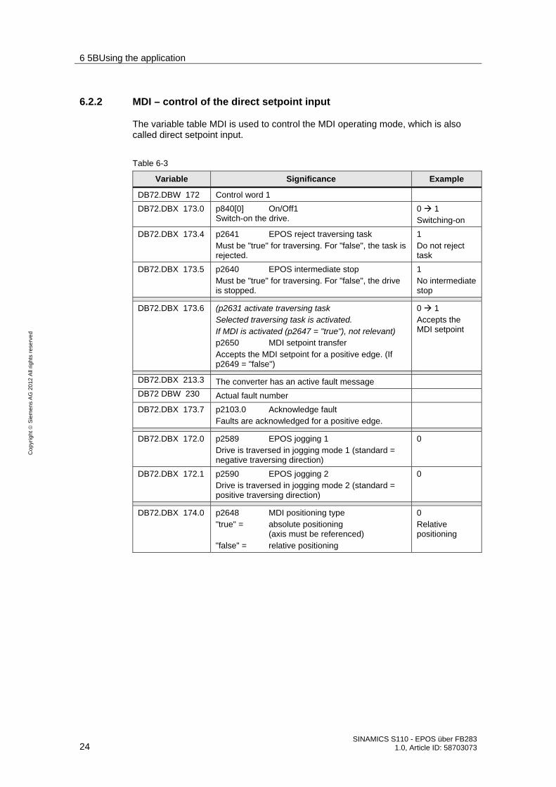
7.1.1 Settings in the hardware configuration
Insert the control and the SINAMICS S110 with the CU305-DP into your project.
Fig. 7-1
You can download the GSD for the SINAMICS S110 under the following link: http://support.automation.siemens.com/WW/view/de/42705323
GSD/GSDML files are required to operate a node/station (e.g. the SINAMICS S110) on the fieldbus (PROFINET (GSDML)) and to register the device with the configuring/engineering tools.

7 6BMore detailed information
SINAMICS S110 - EPOS über FB283 1.0, Article ID: 58703073 41
Co
pyr
igh
t
Sie
me
ns
AG
20
12
All
righ
ts r
ese
rve
d
As telegram, select Siemens telegram 111, after pressing the button. And then drag this and drop it at the first slot of the S110. You can access this list, if you click on the SINAMICS S110 icon on the work area. Also see Fig. 7-3.
Fig. 7-2

7 6BMore detailed information
42 SINAMICS S110 - EPOS über FB283
1.0, Article ID: 58703073
Co
pyr
igh
t
Sie
me
ns
AG
20
12
All
righ
ts r
ese
rve
d
Fig. 7-3
The fieldbus telegram (1.) between the CPU and the SINAMICS S110 comprises a standard telegram, in this particular example Siemens telegram 111. You can also see which I/O devices have been assigned to the device.
Under (2.), you will find the diagnostic address that is required to control acyclic tasks via the FB283.
NOTE FB283 can only operate with the same start addresses for the I/O area.
Load the HW Config into the control system.

7 6BMore detailed information
SINAMICS S110 - EPOS über FB283 1.0, Article ID: 58703073 43
Co
pyr
igh
t
Sie
me
ns
AG
20
12
All
righ
ts r
ese
rve
d
7.1.2 S7 program
Copy the FB283, the UDTs and the variable tables into the block folder. This can either be from the project example or from the library example http://support.automation.siemens.com/WW/view/en/25166781
Call FB283
Create a new FC (e.g. FC72), call this FC in the OB1.
In the FC, call FB283. The call can look like this:
CALL FB283 , DB283
NR_ACHS_DB:=72
LADDR :=256
LADDR_DIAG:=2042
WR_PZD :=P#DB72.DBX172.0 BYTE 24
RD_PZD := P#DB72.DBX212.0 BYTE 24
CONSIST :=TRUE
RESTART :=FALSE
AXIS_NO :=B#16#2
Table 7-1
Signal Comment NR_ACHS_DB Number of the data block for the axis DB.
If there is still no axis DB that can be used (e.g. DB72), then a new one must be created. (see the next page)
LADDR Start of the I/O address of the S110 (cyclic communication PZD)
LADDR_DIAG Diagnostics address of the S110 (acyclic communication), see also HW Config)
WR_PZD Target area for process data, master slave (control words/setpoints) Generally, the axis DB (e.g. DB72) is used here, i.e. in the pointer, the same DB No. must be specified as at the formal parameter "NR_ACHS_DB" The start of the area to be sent is specified in the DB as the start of the area (e.g. DBX172.0) The pointer length depends on the telegram. Standard telegram1: 4 bytes Siemens telegram 111: 24 bytes P#DB72.DBX172.0 BYTE 24 is obtained from this
RD_PZD Target area for process data, master <– slave (status words/actual values) Generally, the axis DB (e.g. DB72) is used here, i.e. in the pointer, the same DB No. must be specified as at the formal parameter "NR_ACHS_DB" The start of the area to be sent is specified in the DB as the start of the area (e.g. DBX212.0) The pointer length depends on the telegram. Standard telegram1: 4 bytes

7 6BMore detailed information
44 SINAMICS S110 - EPOS über FB283
1.0, Article ID: 58703073
Co
pyr
igh
t
Sie
me
ns
AG
20
12
All
righ
ts r
ese
rve
d
Signal Comment Siemens telegram 111: 24 bytes P#DB72.DBX212.0 BYTE 24 is obtained from this
CONSIST Please take the required setting from your hardware configuration. True: The PZD area is "constant over the complete length"; transfer of process data in the area specified under WR_PZD/RD_PZD is realized with SFC 14/15. False: The PZD area is consistent over the unit. Process data is transferred using load/transfer commands.
RESTART Can be used in order to re-initialize/first initialize the block. When powering up, the first initialization is always independent of the value that has been set. As a consequence, in almost all application cases, the parameter is assigned false.
AXIS_NO The axis No. or the DriveObject_ID (DO_ID) of the axis to be addressed should be specified here. As the S110 is a single-axis system, the DO_ID is always 2!
Axis DB
The axis DB contains all of the data that the FB283 requires to execute its functions. The declaration of the axis DB can look like this:
Table 7-2
Address Name Type
0.0 STRUCT
+0.0 Basis UDT30000
+162.0 MDI_Positioning UDT30008
+252.0 Traversing blocks UDT30001
+1928.0 Fault memory UDT30002
2708.0 END_STRUCT
The structure of the axis DB is specified by the UDTs The basis UDT must always be used. As an alternative for the UDT30008 (telegram 111), UDT30010 (telegram 110) or UDT 30009 (closed-loop speed controlled) can be used.
UDTs 30001 and 30002 are optional, and can be removed if they are not required.

7 6BMore detailed information
SINAMICS S110 - EPOS über FB283 1.0, Article ID: 58703073 45
Co
pyr
igh
t
Sie
me
ns
AG
20
12
All
righ
ts r
ese
rve
d
7.2 Configuring the SINAMICS S110
7.2.1 SIMATIC Manager, inserting the SINAMICS S110
• In the SIMATIC Manager tree, select the topmost point and then via "Insert > Program > SINAMICS", select a "SINAMICS S110" type object.
Fig. 7-4
• Select an S110 according to your hardware/firmware version and then press the "OK" button.
Fig. 7-5
7 6BMore detailed information
46 SINAMICS S110 - EPOS über FB283
1.0, Article ID: 58703073
Co
pyr
igh
t
Sie
me
ns
AG
20
12
All
righ
ts r
ese
rve
d
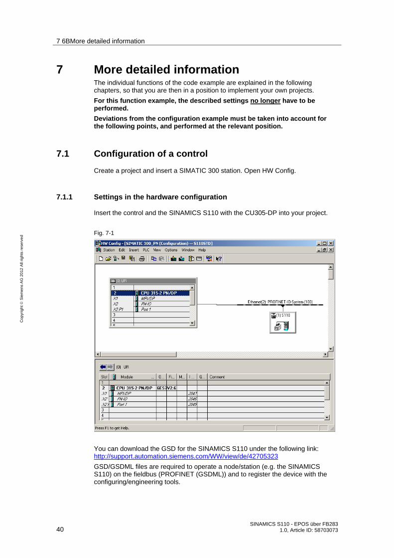
7.2.2 Calling the STARTER parameterizing tool
• Starting from the main path of the SIMATIC Manager, start the parameterizing software STARTER by selecting the "SINAMICS_S110" and double clicking on "Commissioning".
Fig. 7-6
• Then click to the right on the S110 and select "Connect target device".
Fig. 7-7
• The screen form that might open with differences in the online/offline comparison can be closed without having to take any action. A "Load to PG" is manually performed after the factory reset.
• Restore the factory settings by pressing the button. If the button is grayed out, then you must select the S110 in the project tree.

7 6BMore detailed information
SINAMICS S110 - EPOS über FB283 1.0, Article ID: 58703073 47
Co
pyr
igh
t
Sie
me
ns
AG
20
12
All
righ
ts r
ese
rve
d
• After the factory settings have been restored, the data is loaded to the PG by
pressing the button.
7.2.3 STARTER, performing quick commissioning
• Select the "Servo_02 Configuration" menu item and press the
button to start to commission the motor
• The drive must go offline for commissioning. This step is done automatically if you respond to the corresponding message with yes
• In the first screen form, the function module "Basic positioner" must be selected and control mode "[21] closed-loop speed control (with encoder)"
• The point "Power unit" and the points "Motor" to "Measurement system" are correctly preassigned for motors with integrated DRIVE-CLiQ encoder.
Fig. 7-8
• "Mechanics" screen form: In this particular example, a rotary axis is assumed. The position change of the motor shaft through 1° should correspond to 1000 LU (Length Units).
– The gear ratio, load revolutions (1.) / motor revolutions (2.) is 1:1 for this example.

7 6BMore detailed information
48 SINAMICS S110 - EPOS über FB283
1.0, Article ID: 58703073
Co
pyr
igh
t
Sie
me
ns
AG
20
12
All
righ
ts r
ese
rve
d
– One revolution corresponds to 360°, therefore one revolution has 360,000 LU. This value is entered for (3.).
– The modulo correction, which can be activated via (4.), is used to reset the position actual value to 0 after a defined number of LU. In this example, the reset should be after one load revolution, which corresponds to 360,000 LU (5.).
• In the screen form "Process data exchange", select the "PROFIdrive telegram" as the setpoint source, and "[111] SIEMENS telegram 111, PZD-12/12" as telegram type.
• You can then check the values that you have entered in the "Summary" screen form. The configuration is completed by pressing "Finish".
• Go back on line and load the data to the target device. This is either done using the online/offline comparison screen form that then appears, or using the "Load to target device" button in the screen form that subsequently opens. Set the check mark for "After loading, copy RAM to ROM".

7 6BMore detailed information
SINAMICS S110 - EPOS über FB283 1.0, Article ID: 58703073 49
Co
pyr
igh
t
Sie
me
ns
AG
20
12
All
righ
ts r
ese
rve
d
7.2.4 STARTER, performing motor identification
• After quick commissioning has been completed, a stationary measurement can be performed. For DRIVE-CLiQ motors, a rotating (turning) measurement is not required, as very precise motor data have already been stored. For other motors, a rotating (turning) measurement should be performed. This is realized analogous to the subsequently described "Stationary measurement".
• To activate the measurement, via "SERVO_02CommissioningStationary/turning measurement" (1.) open the following screen form.
Fig. 7-9
• For the measuring type, select "Stationary measurement" (2.) and then press on "Activate measurement" (3.).
• To start the motor identification, in the project navigator, select the menu item "Commissioning" and activate by double clicking on the "Control panel".
Fig. 7-10
• Press the "Assume control priority" button and carefully observe the safety notes. Then activate "Enables".
WARNING
Only use the motor identification function if the motor cannot be turned by a connected load.
In order to avoid an external load accelerating the motor, we recommend that the motor is locked for the stationary motor identification routine.

7 6BMore detailed information
50 SINAMICS S110 - EPOS über FB283
1.0, Article ID: 58703073
Co
pyr
igh
t
Sie
me
ns
AG
20
12
All
righ
ts r
ese
rve
d
Fig. 7-11
• 1.) If the control panel on your PG/PC is not completely shown, then press the
button.
• The motor data identification routine is started by pressing the button. Do not change from the STARTER software into another task, as otherwise, the motor data identification routine will be interrupted for safety reasons.
• Please wait until the button changes back to the button.
• By pressing the button, return the control priority to the S7 control.

7 6BMore detailed information
SINAMICS S110 - EPOS über FB283 1.0, Article ID: 58703073 51
Co
pyr
igh
t
Sie
me
ns
AG
20
12
All
righ
ts r
ese
rve
d
7.2.5 Basic Safety settings via F_DI
• Activate the Safety screen form by selecting "SERVO_02FunctionsSafety Integrated" (1.).
• In order to change the settings, you must press "Change settings“ (2.). If you have already assigned a Safety password, you will now be asked to enter this.
Fig. 7-12
For the Basis Safety functions, three functions are available: SS1 (Safe Stop 1), STO (Safe Torque Off) and SBC (Safe Brake Control – external "Safe Brake Module" required). You can connect these via a Safety input.
Fig. 7-13
• In the drop-down menu, select "STO/SBC/SS1 via terminal" (1.). • The "Safe Stop1 delay time" (SS1) (2.) specifies how long the drive should be
braked along the fast stop ramp after pressing the Emergency Stop button before STO is initiated. For SS1 = 0s, STO is immediately initiated.
• The "Safe Brake Control" (SBC) (3.) is not used in this example. However, it can be enabled from the selection menu.
7 6BMore detailed information
52 SINAMICS S110 - EPOS über FB283
1.0, Article ID: 58703073
Co
pyr
igh
t
Sie
me
ns
AG
20
12
All
righ
ts r
ese
rve
d
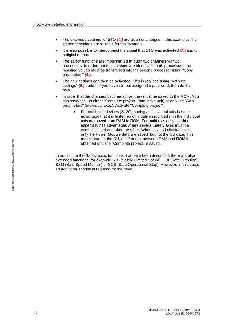
• The extended settings for STO (4.) are also not changed in this example. The standard settings are suitable for this example.
• It is also possible to interconnect the signal that STO was activated (7.) e.g. to a digital output.
• The safety functions are implemented through two channels via two processors. In order that these values are identical in both processors, the modified values must be transferred into the second processor using "Copy parameters" (5.).
• The new settings can then be activated. This is realized using "Activate settings" (6.) button. If you have still not assigned a password, then do this now.
• In order that the changes become active, they must be saved to the ROM. You can save/backup either "Complete project" (total drive unit) or only the "Axis parameters" (individual axes). Activate "Complete project".
• For multi-axis devices (S120), saving as individual axis has the advantage that it is faster, as only data associated with the individual axis are saved from RAM to ROM. For multi-axis devices, this especially has advantages where several Safety axes must be commissioned one after the other. When saving individual axes, only the Power Module data are saved, but not the CU data. This means that on the CU, a difference between RAM and ROM is obtained until the "Complete project" is saved.
In addition to the Safety basic functions that have been described, there are also extended functions, for example SLS (Safely-Limited Speed), SDI (Safe Direction), SSM (Safe Speed Monitor) or SOS (Safe Operational Stop). However, in this case, an additional license is required for the drive.

7 6BMore detailed information
SINAMICS S110 - EPOS über FB283 1.0, Article ID: 58703073 53
Co
pyr
igh
t
Sie
me
ns
AG
20
12
All
righ
ts r
ese
rve
d
7.2.6 Overview and settings of the position controller screen forms
You can find the position controller settings under the main item, Technology. They are subdivided into 4 points.
Fig. 7-14

7 6BMore detailed information
54 SINAMICS S110 - EPOS über FB283
1.0, Article ID: 58703073
Co
pyr
igh
t
Sie
me
ns
AG
20
12
All
righ
ts r
ese
rve
d
Mechanics
The mechanical settings were already made when commissioning. As a consequence, no changes have to be made here.
Fig. 7-15
In addition to the settings already made for quick commissioning, when required, the backlash value can be set (1.), which is then taken into account for the closed-loop position control.
For absolute encoders, position tracking is important (2.); this ensures that encoder overflows are counted, and even if encoder overflows occur, the system can still correctly position.
Detailed information is provided in the S110 Function Manual on both of these topics.

7 6BMore detailed information
SINAMICS S110 - EPOS über FB283 1.0, Article ID: 58703073 55
Co
pyr
igh
t
Sie
me
ns
AG
20
12
All
righ
ts r
ese
rve
d
Position actual value preparation
For position actual value preparation, various settings can be made to adapt the position actual value. However, for this example, no adaptations are required. Generally, when using EPOS, only a few changes are required in the screen form, as EPOS has its own reference system to which it refers.
Fig. 7-16

7 6BMore detailed information
56 SINAMICS S110 - EPOS über FB283
1.0, Article ID: 58703073
Co
pyr
igh
t
Sie
me
ns
AG
20
12
All
righ
ts r
ese
rve
d
Position controller
The position controller comprises two screen forms.
• Setpoint position controller
• Position controller
The setpoint sources and position actual value source can be adapted for the setpoints for the position controller. As we are using EPOS, EPOS already preassigns these values, and they should not be changed.
Fig. 7-17
• The position setpoint is filtered using a PT1 element with the selected time constant via the position setpoint filter (1.). This filtering reduces the pre-control dynamics and jerk limiting.
• With pre-control (2.), a percentage (0 – 200 %) can be entered, with which the position setpoint precontrols a speed/velocity on the speed controller, bypassing the position controller. (0 % = deactivated)
• With pre-control balancing (3.), the position setpoint signal can be filtered again in order to emulate the behavior of the speed control loop. To achieve this, a dead time filter (0.0 – 2.0), which represents the factor of the position controller sampling time (1s), and a PT1 element (0 – 100 ms) are available.

7 6BMore detailed information
SINAMICS S110 - EPOS über FB283 1.0, Article ID: 58703073 57
Co
pyr
igh
t
Sie
me
ns
AG
20
12
All
righ
ts r
ese
rve
d
With the position controller screen form, the settings of the position controller can be adapted, the controller enable assigned, and the outputs of the position controller interconnected.
Fig. 7-18
• The position controller can be optimized using the P gain (1.) and the reset time (2.).
• In addition, the P component can be modified using an adaptation (3.). This can be used to variably scale the P gain. This means that different position controller settings can be set for various situations.
• The maximum permissible traversing velocity is set for limitation active(4.).

7 6BMore detailed information
58 SINAMICS S110 - EPOS über FB283
1.0, Article ID: 58703073
Co
pyr
igh
t
Sie
me
ns
AG
20
12
All
righ
ts r
ese
rve
d
Monitoring
The monitoring function comprises three screen forms:
• Position and standstill (zero speed) monitoring
• Following error monitoring
• Cams
In these screen forms, it is possible to set the position monitoring functions.
NOTE In this case, all values that refer to LU should be increased as a minimum by a factor of 10, as the set value of 360,000 LU is significantly higher than the factory value of 10,000 LU, for which the values have been selected.
Note The various monitoring functions can be deactivated by entering 0.
The corresponding values should be parameterized under "Positioning/standstill monitoring".
Fig. 7-19
7 6BMore detailed information
SINAMICS S110 - EPOS über FB283 1.0, Article ID: 58703073 59
Co
pyr
igh
t
Sie
me
ns
AG
20
12
All
righ
ts r
ese
rve
d
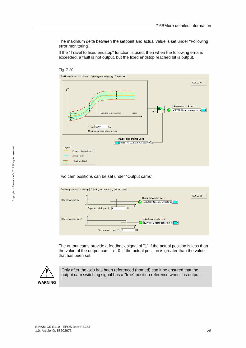
The maximum delta between the setpoint and actual value is set under "Following error monitoring".
If the "Travel to fixed endstop" function is used, then when the following error is exceeded, a fault is not output, but the fixed endstop reached bit is output.
Fig. 7-20
Two cam positions can be set under "Output cams".
The output cams provide a feedback signal of "1" if the actual position is less than the value of the output cam – or 0, if the actual position is greater than the value that has been set.
WARNING
Only after the axis has been referenced (homed) can it be ensured that the output cam switching signal has a "true" position reference when it is output.
7 6BMore detailed information
60 SINAMICS S110 - EPOS über FB283
1.0, Article ID: 58703073
Co
pyr
igh
t
Sie
me
ns
AG
20
12
All
righ
ts r
ese
rve
d
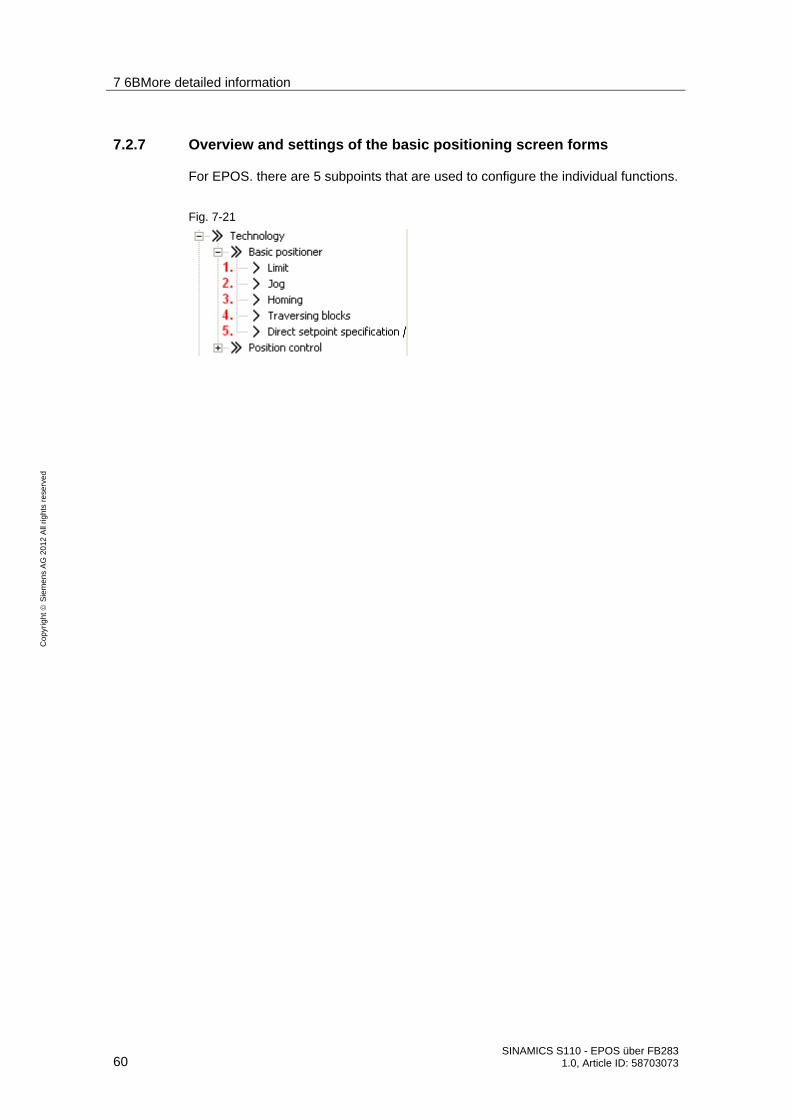
7.2.7 Overview and settings of the basic positioning screen forms
For EPOS. there are 5 subpoints that are used to configure the individual functions.
Fig. 7-21

7 6BMore detailed information
SINAMICS S110 - EPOS über FB283 1.0, Article ID: 58703073 61
Co
pyr
igh
t
Sie
me
ns
AG
20
12
All
righ
ts r
ese
rve
d
Limitation
The limitation comprises two tabs. One for the traversing range limitation and one for the traversing profile limitation.
For the traversing range limitation, the software limit switches and stop output cams are parameterized. This parameterization is only required if you want to use the associated functions.
Fig. 7-22
For the software limit switches (1.), the end positions are specified in LU, which the drive must not pass. Generally, these end positions are located in front of the stop output cams.
The software limit switches output various alarms:
• A7469 or A7470 Target position in a traversing block exceeds the software limit switch range in the negative/positive direction
• A7477 or A7478 The target position when actually traversing is less than/greater than the negative/positive end position
• A7479 or A7480 Axis is located at a negative/positive limit switch position – an active traversing block has been canceled/interrupted.
• F7481 or F7482 Software limit switch, negative/positive activated.
Using "Software limit switch activation" (2.) , the limit switches can be activated; however, only if the modulo correction is not active and the axis has been referenced (homed). When using telegram 111, the software limit switch is activated using bit 14 of positioning control word 2.

7 6BMore detailed information
62 SINAMICS S110 - EPOS über FB283
1.0, Article ID: 58703073
Co
pyr
igh
t
Sie
me
ns
AG
20
12
All
righ
ts r
ese
rve
d
There are also the stop output cams (3.). Generally, these are interconnected with sensors at the digital inputs. A response is initiated if the output stop cam is activated (passed).
NOTE A fault as standard response can be adapted in the expert list using p2117 and p2119 to become an alarm.
The stop output cams can be activated using "Stop output cam activation" (4.). This is realized for a telegram using bit 15 of the positioning control word 2.
The limits for maximum velocity, acceleration, deceleration and jerk can be entered under the traversing profile limitation tab. Just the same as for the monitoring functions, these values can be increased, as it involves a higher resolution than in the basic settings. The mechanical load on a motor operating under no-load conditions is low. This means that the positioning velocity can be set to the maximum velocity without any problem, and the acceleration and deceleration rates can be correspondingly increased. When a mechanical system is connected to the motor, then the load limits of the mechanical system must be taken into consideration.
Fig. 7-23
For the velocity, the maximum velocity can be set in 1000 LU/min. However, this must lie below the maximum motor speed. The value converted into speed is shown in the screen form under Corresponds to speed.
The acceleration rate of the drive can be determined using acceleration. This is comparable with the acceleration time. You must perform the following calculation if you want to convert the acceleration rate into an acceleration time:
[ ]stimeonaccelerati
sLU
onacceleratis
LUvelocity
=
•
2
1000.max
min60
min1000
.max

7 6BMore detailed information
SINAMICS S110 - EPOS über FB283 1.0, Article ID: 58703073 63
Co
pyr
igh
t
Sie
me
ns
AG
20
12
All
righ
ts r
ese
rve
d
Analogous to acceleration, there is also deceleration. Using the same formula, this can be converted into a deceleration time.
The jerk limitation specifies the jerk when the drive accelerates. As standard, this is not active but must be separately activated. If it is active, then it rounds-off the ramps. The rounding-off time can be calculated as follows:
[ ]stimeoffrounding
sLUjerk
sLUonaccelerati
−=
3
2
1000.max
1000.max

7 6BMore detailed information
64 SINAMICS S110 - EPOS über FB283
1.0, Article ID: 58703073
Co
pyr
igh
t
Sie
me
ns
AG
20
12
All
righ
ts r
ese
rve
d
Jogging
Here, there are two screen forms; one for configuring and one for diagnostics.
When configuring, you can toggle between the digital and analog inputs/outputs of the jog function by making the appropriate selection at the top left. All of the settings of this screen form are correctly set when selecting the telegram, and do not have to be changed.
Fig. 7-24
By clicking on the jog block (1.), the box to configure the jog setpoints is opened. Here, you should increase the values, as they are too low for the mechanical settings that have been made.

7 6BMore detailed information
SINAMICS S110 - EPOS über FB283 1.0, Article ID: 58703073 65
Co
pyr
igh
t
Sie
me
ns
AG
20
12
All
righ
ts r
ese
rve
d
Fig. 7-25
The traversing velocity when jogging can be defined using the setpoint velocity values (1.).
The traversing distance settings (2.) specify how far the drive is traversed for incremental jogging. Incremental jogging must be separately activated, and is then controlled using the same inputs as for normal jogging.
In the ramp-function generator, you can set an up ramp, which is only applicable for jogging.

7 6BMore detailed information
66 SINAMICS S110 - EPOS über FB283
1.0, Article ID: 58703073
Co
pyr
igh
t
Sie
me
ns
AG
20
12
All
righ
ts r
ese
rve
d
An overview of the analog and digital inputs and outputs is provided in the diagnostics screen form.
Fig. 7-26
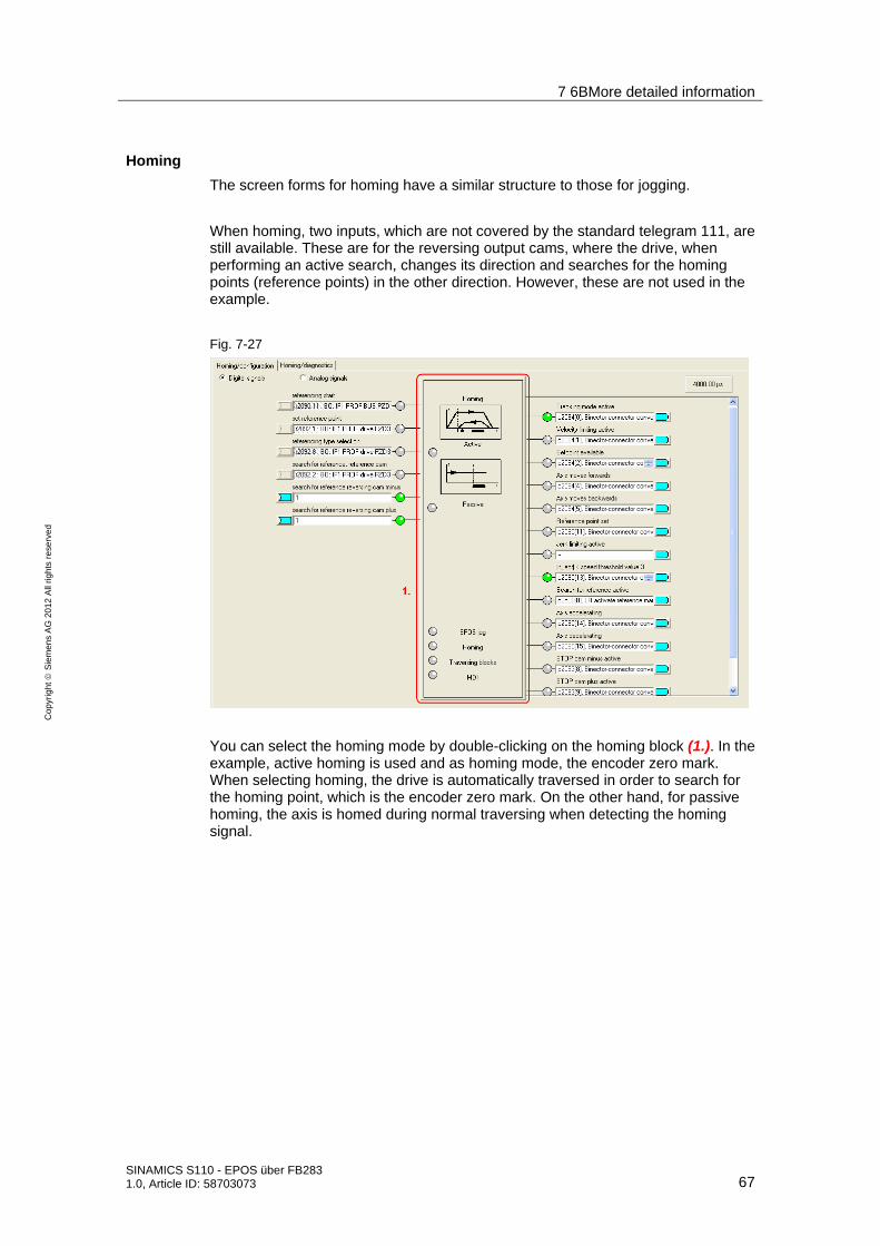
7 6BMore detailed information
SINAMICS S110 - EPOS über FB283 1.0, Article ID: 58703073 67
Co
pyr
igh
t
Sie
me
ns
AG
20
12
All
righ
ts r
ese
rve
d
Homing
The screen forms for homing have a similar structure to those for jogging.
When homing, two inputs, which are not covered by the standard telegram 111, are still available. These are for the reversing output cams, where the drive, when performing an active search, changes its direction and searches for the homing points (reference points) in the other direction. However, these are not used in the example.
Fig. 7-27
You can select the homing mode by double-clicking on the homing block (1.). In the example, active homing is used and as homing mode, the encoder zero mark. When selecting homing, the drive is automatically traversed in order to search for the homing point, which is the encoder zero mark. On the other hand, for passive homing, the axis is homed during normal traversing when detecting the homing signal.

7 6BMore detailed information
68 SINAMICS S110 - EPOS über FB283
1.0, Article ID: 58703073
Co
pyr
igh
t
Sie
me
ns
AG
20
12
All
righ
ts r
ese
rve
d
The following screen form is available for active homing for incremental encoders.
Fig. 7-28
You can select between different homing types(1.) and homing modes (2.).
The possible homing modes are active (specifically requested automatic homing) and passive (the axis is automatically homed during normal traversing)
For the homing mode, the following can be selected for the reference signal:
• Reference cam and encoder zero mark
• Encoder zero mark
• External zero mark
The settings for the approach velocities (3.) should be set corresponding to the mechanical system. In this example, this means that the value should be increased, as we have set a relatively high resolution.
There are two options for correcting the position value to the required value: (4.) 1. Home position/coordinate
The value is entered, which is the position actual value at the zero mark. This means that for active homing, the motor remains stationary at the encoder zero mark, which represents the home position.

7 6BMore detailed information
SINAMICS S110 - EPOS über FB283 1.0, Article ID: 58703073 69
Co
pyr
igh
t
Sie
me
ns
AG
20
12
All
righ
ts r
ese
rve
d
2. Home position offset It is specified as to how many LU the home position should be shifted in the positive direction. This means that for active homing, the motor remains stationary at the home position (0 LU).
For absolute encoders, in the screen form "Active homing", there is just one button "Absolute encoder adjustment" as well as one input field for the home position coordinates. Absolute encoders have the advantage that they do not have to be re-homed each time that the system is switched on.
Passive homing is also possible for absolute encoders.
The screen form for passive homing is the same both for absolute as well as incremental encoders; however, it is not used for the example.
Fig. 7-29
For passive homing, you can parameterize two measuring probes as home position source for passive homing. (1.) For telegram 111, the active measuring probe is selected via fieldbus.
Using the edge evaluation (2.), you can set whether measuring probe high or low active is used.
You can set whether a position actual value correction should be taken into account for relative positioning (3.) or only for absolute positioning.
When entering the inner and outer windows (4.), you can set separate correction values. This means that the measuring probe width can be compensated.

7 6BMore detailed information
70 SINAMICS S110 - EPOS über FB283
1.0, Article ID: 58703073
Co
pyr
igh
t
Sie
me
ns
AG
20
12
All
righ
ts r
ese
rve
d
Otherwise, this would automatically result in different zero positions, dependent on the direction of travel.
Traversing blocks
For the traversing blocks, just as for the previous, there is one screen form for configuring
and one for diagnostics.
All of the settings of this screen form are correctly set when selecting the telegram, and should not be changed.
Fig. 7-30
You can get to the traversing block screen form via the block for the traversing block (1.).

7 6BMore detailed information
SINAMICS S110 - EPOS über FB283 1.0, Article ID: 58703073 71
Co
pyr
igh
t
Sie
me
ns
AG
20
12
All
righ
ts r
ese
rve
d
Fig. 7-31
Here, you can parameterize the traversing blocks. Parameters that are not required are grayed out. The sequence is defined by the block number and not by the sequence of the list; this means that when making subsequent changes, a new line can be simply attached with the corresponding number.
This example is only intended to show what traversing blocks can look like.
More detailed information on setting traversing programs is provided in the S110 Function Manual.

7 6BMore detailed information
72 SINAMICS S110 - EPOS über FB283
1.0, Article ID: 58703073
Co
pyr
igh
t
Sie
me
ns
AG
20
12
All
righ
ts r
ese
rve
d
Direct setpoint input MDI
The direct setpoint input / MDI, just like the previous points, is subdivided into 2 tab sheets for configuration and diagnostics.
All of the settings of this screen form are correctly set when selecting the telegram, and should not be changed.
You can assign the input signals for MDI here. As standard, all of the inputs are already preassigned via fieldbus. By selecting the "Positioning MDI" block (1.), you can set 4 fixed setpoints, which are active if a setpoint has not been specified via the bus.
Fig. 7-32
Fig. 7-33
In this screen form, you can set the setpoints that are used as long as they are not externally entered. As in this example the setpoints are received via the control (telegram 111), changes in this screen form have no effect for this example.

7 6BMore detailed information
SINAMICS S110 - EPOS über FB283 1.0, Article ID: 58703073 73
Co
pyr
igh
t
Sie
me
ns
AG
20
12
All
righ
ts r
ese
rve
d
7.2.8 Completing commissioning
• To complete, you only have to backup the SINAMICS S110 configuration in the ROM memory of the converter. To do this, in the project navigator, select the menu item S110_CU305_DP.
Fig. 7-34
• In the toolbar, press the button.
• Please wait until the operation has been completed.

7 6BMore detailed information
74 SINAMICS S110 - EPOS über FB283
1.0, Article ID: 58703073
Co
pyr
igh
t
Sie
me
ns
AG
20
12
All
righ
ts r
ese
rve
d
7.3 FB283 error messages
7.3.1 single.ErrorNumbr
Table 7-3
ErrorNumbr Significance
10XY Network 2: SFC6 RET_VAL <> 0 11XY Network 2: obligatory Udt30000 not available in the axis DB
or is not at the start of the axis DB Remedy 1.) Reboot the CPU 2.) Create the axis DB corresponding to the documentation, e.g. UDT30000, UDT30001, ..., at the end, own variables.
20XY Network 3: SFC15 RET_VAL <> 0, error when writing process data
21XY Network 3: SFC21 RET_VAL <> 0, error when deleting the status words
22XY Network 3: SFC20 RET_VAL <> 0, error when copying from #rdz to #hilf_zsw
30XY Network 4: #AuftrArt has an invalid value
40XY Network 5: single.taski = 0
41XY Network 5: single.taski has an invalid value
42XY Network 5: The task 30011 "Pre-assign traversing blocks 0..63" cannot be started with a positive edge of bit single.RD
43XY Network 5: The task 30002 "Read-out fault memory" cannot be started with a positive edge of bit single.WR
50XY Network 6: #AuftrSchritt has an invalid value
51XY Network 6: Incorrect return value (ParameterValues.Format) from SINAMICS S120
60XY Network 7: #AuftrSchritt has an invalid value
61XY Network 7: Internal program error
70XY Network 8: #AuftrSchritt has an invalid value
71XY Network 8: singl.Ind < 0 (permitted values: 0...63)
72XY Network 8: singl.Ind > 63 (permitted values: 0...63)
80XY Network 9: #AuftrSchritt has an invalid value 81XY Network 9: optional UDT30001 not available in the axis DB,
this means that the task "Read/write traversing block" cannot be executed. Remedy 1.) Reboot the CPU 2.) Create the axis DB corresponding to the documentation, e.g. UDT30000, UDT30001, ..., at the end, own variables.
82XY Network 9: single.Ind > 63 (permitted values: 0...63)
83XY Network 9: single.Ind < 0 (permitted values: 0...63)
84XY Network 9: single.Data > 63 (permitted values: 0...63)
85XY Network 9: single.Data < single.Ind (note: single.Ind must be <= single.Data)
86XY Network 17: single.Ind > 10 (permitted values: 1...10)
87XY Network 17: single.Ind < 1 (permitted values: 1...10)
88XY Network 17: single.Data > 10 (permitted values: 1...10)
89XY Network 17: single.Data < 1 (permitted values: 1...10)

7 6BMore detailed information
SINAMICS S110 - EPOS über FB283 1.0, Article ID: 58703073 75
Co
pyr
igh
t
Sie
me
ns
AG
20
12
All
righ
ts r
ese
rve
d
8AXY Network 17: single.Ind =< single.Data (Note: single.Ind must be >= single.Data)
90XY Network 10: #AuftrSchritt has an invalid value 91XY Network 10: optional UDT30002 not available in the axis DB,
this means that the task "Read-out fault memory" cannot be executed. Remedy 1.) Reboot the CPU 2.) Create the axis DB corresponding to the documentation, e.g. UDT30000, UDT30001, ..., at the end, own variables.
92XY Network 10: Internal program error when generating the task - jump bar
93XY Network 10: Internal program error when evaluating the task - jump bar
94XY Network 10: Internal program error when evaluating the task - fault code
95XY Network 10: Internal program error when evaluating the task - fault number
96XY Network 10: Internal program error when evaluating the task - fault value
A0XY Network 12: #AuftrSchritt has an invalid value
B0XY Network 12: #AuftrSchritt has an invalid value
B1XY Network 12: A value was not able to be read
B2XY Network 12: Internal program error when evaluating the task.
C0XY Network 13: #AuftrSchritt has an invalid value
C1XY Network 13: A value was not able to be written
D0XY Network 14: Error for non-cyclic write access using SFB53 (SFB errors, refer below)
D1XY Network 14: Error for non-cyclic read access using SFB52
D2XY Network 14: Internal program error
E0XY Network 15: Error for non-cyclic access using SFB
E1XY
Network 14/15: Request Error task completed with error (Response ID = 0x81/82); additional tasks canceled. For a more precise error number, refer to instance DB DBW322 (response.Error_Nr). Significance of the error numbers, refer to the Manual, Chapter "Acyclic communication"
F0XY Network 17/18: #AuftrSchritt has an invalid value
F1XY Network 17: Incorrect return value (ParameterValues.Format) from SINAMICS S120

7 6BMore detailed information
76 SINAMICS S110 - EPOS über FB283
1.0, Article ID: 58703073
Co
pyr
igh
t
Sie
me
ns
AG
20
12
All
righ
ts r
ese
rve
d
7.3.2 SINAMICS S110
A detailed description of the SINAMICS S110 error messages is provided in the associated List Manual (Chapter 3.2 List of faults and alarms):
http://support.automation.siemens.com/WW/view/de/49129886
Or in the STARTER online help.
7 6BMore detailed information
SINAMICS S110 - EPOS über FB283 1.0, Article ID: 58703073 77
Co
pyr
igh
t
Sie
me
ns
AG
20
12
All
righ
ts r
ese
rve
d
7.4 FAQ on FB283
Q: The system blocks SFC 14/15 signal an area length error in the diagnostics buffer of the S7 CPU?
A: Check the access width of the WR_PZD and RD_PZD in the FB283 call with HW Config. The access width (in bytes) must be the same size. The PROFIBUS address must be correct.
Q: Cyclic communication runs, but acyclic communication does not function?
A1:Check the diagnostics address (this can be found in HW Config). Generally, the preset diagnostics address of the example is not appropriate.
A2:Check the axis object number. The drive object number of the axis in STARTER corresponds to the axis object number in the FB283 call.
Q: Is it possible to acyclically access a drive line-up of several SINAMICS connected in parallel?
A : No - The task interface of the FB283 only permits acyclic access operations. If several SINAMICS are to be accessed, then this must be done sequentially.
Q: Is it possible to acyclically access a CU320 with several axes in parallel?
A: No - as PROFIBUS node, a CU320 has only ONE diagnostics address – accessing axes of a CU must be realized sequentially.
Q: Why does the S7 CPU signal an area length error for the FB283 in the diagnostics buffer when using a multi-instance for several drives?
A : Within a multi-instance, the FB283 can only manage a limited number of axis data blocks. In tests, this limit was defined to be 6. If more axes are managed, then the FB283 should be used under a new name (for example FB284).
Q: Why does the FB283 output an error when attempting to write to one/several traversing blocks on an axis?
A : Writing to one/several traversing blocks requires correct parameterization of the traversing blocks - incorrect traversing blocks are not transferred or the transfer is canceled for a traversing block at this position.
Q: Why can parameters of an OA application not be read out/written to with a parameter value greater than 30000?
A : There is an internal limit of all readable/writable parameters in the FB283. This limit is 29999. In this case, standard blocks SF52 / 53 must be used.
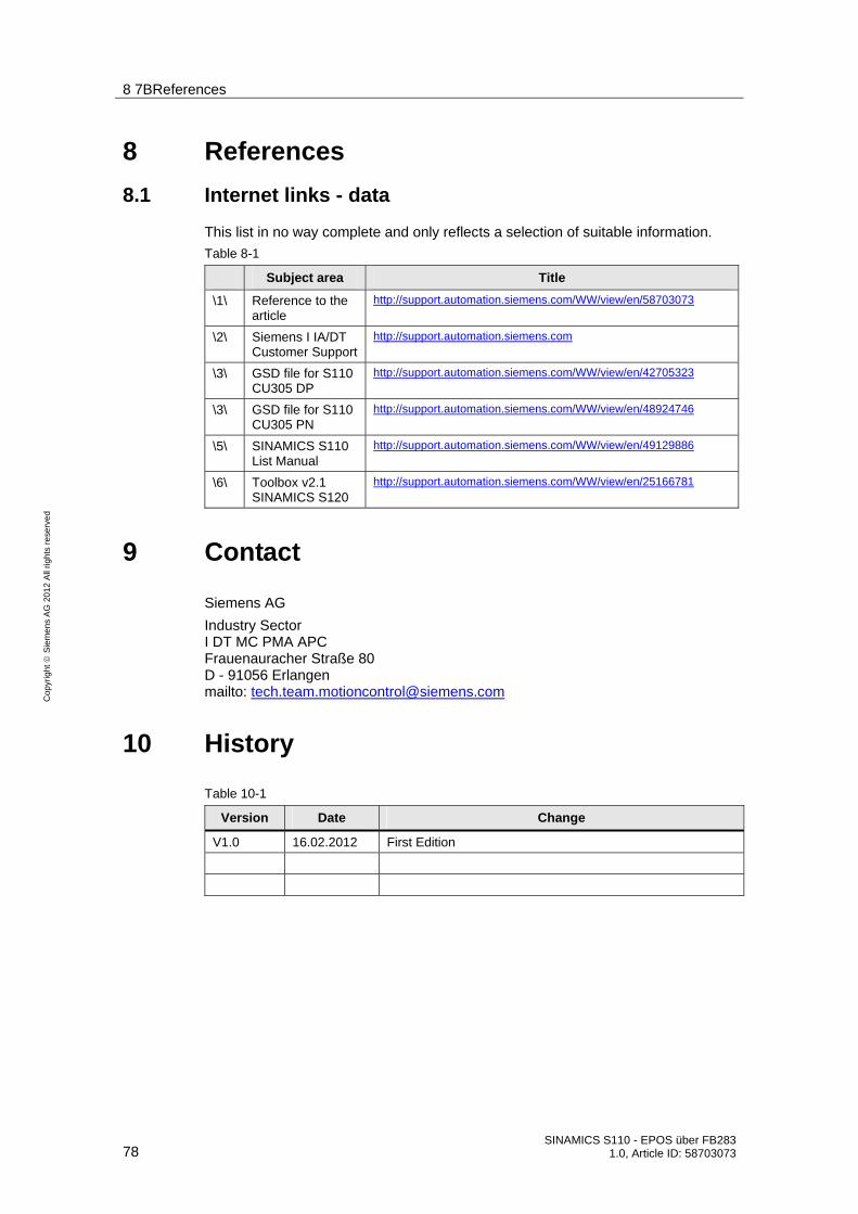
8 7BReferences
78 SINAMICS S110 - EPOS über FB283
1.0, Article ID: 58703073
Co
pyr
igh
t
Sie
me
ns
AG
20
12
All
righ
ts r
ese
rve
d
8 References
8.1 Internet links - data
This list in no way complete and only reflects a selection of suitable information.
Table 8-1
Subject area Title
\1\ Reference to the article
http://support.automation.siemens.com/WW/view/en/58703073
\2\ Siemens I IA/DT Customer Support
http://support.automation.siemens.com
\3\ GSD file for S110 CU305 DP
http://support.automation.siemens.com/WW/view/en/42705323
\3\ GSD file for S110 CU305 PN
http://support.automation.siemens.com/WW/view/en/48924746
\5\ SINAMICS S110 List Manual
http://support.automation.siemens.com/WW/view/en/49129886
\6\ Toolbox v2.1 SINAMICS S120
http://support.automation.siemens.com/WW/view/en/25166781
9 Contact
Siemens AG
Industry Sector I DT MC PMA APC Frauenauracher Straße 80 D - 91056 Erlangen mailto: [email protected]
10 History
Table 10-1
Version Date Change
V1.0 16.02.2012 First Edition