Simulation Based Evaluation of Highway Road Scenario between DSRC/802.11p MAC Protocol...
17
Journal of Transportation Technologies, 2013, 3, 88-104 http://dx.doi.org/10.4236/jtts.2013.31009 Published Online January 2013 (http://www.scirp.org/journal/jtts) Simulation Based Evaluation of Highway Road Scenario between DSRC/802.11p MAC Protocol and STDMA for Vehicle-to-Vehicle Communication Vaishali D. Khairnar, Srikhant N. Pradhan Computer Department, Institute of Technology Nirma University, Ahmadabad, India Email: [email protected], [email protected] Received October 7, 2012; revised November 10, 2012; accepted November 23, 2012 ABSTRACT In this paper the DSRC/IEEE 802.11p Medium Access Control (MAC) method of the vehicular communication has been simulated on highway road scenario with periodic broadcast of packets in a vehicle-to-vehicle situation. IEEE 802.11p MAC method is basically based on carrier sense multiple accesses (CSMA) where nodes listen to the wireless channel before sending the packets. If the channel is busy, the vehicle node must defer its access and during high utili- zation periods this could lead to unbounded delays. This well-known property of CSMA is undesirable for critical communications scenarios. The simulation results reveal that a specific vehicle is forced to drop over 80% of its pack- ets/messages because no channel access was possible before the next message/packet was generated. To overcome this problem, we propose to use self-organizing time division multiple access (STDMA) for real-time data traffic between vehicles. Our initial results indicate that STDMA outperforms CSMA for time-critical traffic safety applications in ad- hoc vehicular networks. Keywords: STDMA; CSMA; MAC; DSRC; IEEE 802.11p; Vehicle-to-Vehicle Etc 1. Introduction Vehicular Ad-hoc Network area has attracted a lot of attention during the last few years due to the range of new applications enabled by emerging wireless commu- nication technologies. Existing vehicle-to-vehicle safety systems together with new cooperative systems use wire- less data communication between vehicles which can po- tentially decrease the number of accidents on the high- way road in India. A tremendous interest in cooperating safety systems for vehicles has been notified through the extensive range of project activities around all over the world. Lane departure warning messages merge assis- tance and emergency vehicle routing are all examples of applications [1]. These new traffic safety systems implies increased re- quirements on the wireless communication and the chal- lenge is not only to overcome the behavior of the unpre- dictable wireless channel but also to cope with rapid network topology changes together with strict timing and reliability requirements. The timing requirements can be deduced from the fact that it is only relevant to commu- nicate about an upcoming dangerous situation before the situation is a fact and perhaps can be avoided (e.g., com- municate a probable collision before the vehicles are colliding) [2]. One thing in this respect is how the shared communication channel should be divided in a fair and predictable way among the participating users. This is done through the medium access control (MAC). Much attention within the standardization of vehicle communi- cation systems has been devoted to enhancing the MAC by introducing different quality of service (QoS) classes for data traffic with different priorities [3]. The MAC layer in a traffic safety application is unlikely to need many different service classes or transfer rates. Instead, to guarantee that time-critical communication tasks meet their deadlines, the MAC layer must first of all provide a finite worst case access time to the channel. Once chan- nel access is a fact, different coding strategies, diversity techniques and retransmission schemes can be used to achieve the required correctness and robustness against the impairments of the unpredictable wireless channel. Information that is delivered after the deadline in a criti- cal real-time communication system is not only useless, but implies severe consequences for the traffic safety system. This problem has also been pointed out in [4]. The IEEE 802.11p, also known as Dedicated Short- Range Communication (DSRC), is an upcoming WLAN standard intended for future traffic safety systems. Cur- rently this is the only standard with support for direct Copyright © 2013 SciRes. JTTs
Transcript of Simulation Based Evaluation of Highway Road Scenario between DSRC/802.11p MAC Protocol...
Journal of Transportation Technologies, 2013, 3, 88-104 http://dx.doi.org/10.4236/jtts.2013.31009 Published Online January 2013 (http://www.scirp.org/journal/jtts)
Simulation Based Evaluation of Highway Road Scenario between DSRC/802.11p MAC Protocol and STDMA for
Vehicle-to-Vehicle Communication
Vaishali D. Khairnar, Srikhant N. Pradhan Computer Department, Institute of Technology Nirma University, Ahmadabad, India
Email: [email protected], [email protected]
Received October 7, 2012; revised November 10, 2012; accepted November 23, 2012
ABSTRACT
In this paper the DSRC/IEEE 802.11p Medium Access Control (MAC) method of the vehicular communication has been simulated on highway road scenario with periodic broadcast of packets in a vehicle-to-vehicle situation. IEEE 802.11p MAC method is basically based on carrier sense multiple accesses (CSMA) where nodes listen to the wireless channel before sending the packets. If the channel is busy, the vehicle node must defer its access and during high utili- zation periods this could lead to unbounded delays. This well-known property of CSMA is undesirable for critical communications scenarios. The simulation results reveal that a specific vehicle is forced to drop over 80% of its pack- ets/messages because no channel access was possible before the next message/packet was generated. To overcome this problem, we propose to use self-organizing time division multiple access (STDMA) for real-time data traffic between vehicles. Our initial results indicate that STDMA outperforms CSMA for time-critical traffic safety applications in ad- hoc vehicular networks. Keywords: STDMA; CSMA; MAC; DSRC; IEEE 802.11p; Vehicle-to-Vehicle Etc
1. Introduction
Vehicular Ad-hoc Network area has attracted a lot of attention during the last few years due to the range of new applications enabled by emerging wireless commu- nication technologies. Existing vehicle-to-vehicle safety systems together with new cooperative systems use wire- less data communication between vehicles which can po- tentially decrease the number of accidents on the high- way road in India. A tremendous interest in cooperating safety systems for vehicles has been notified through the extensive range of project activities around all over the world. Lane departure warning messages merge assis- tance and emergency vehicle routing are all examples of applications [1].
These new traffic safety systems implies increased re- quirements on the wireless communication and the chal- lenge is not only to overcome the behavior of the unpre- dictable wireless channel but also to cope with rapid network topology changes together with strict timing and reliability requirements. The timing requirements can be deduced from the fact that it is only relevant to commu- nicate about an upcoming dangerous situation before the situation is a fact and perhaps can be avoided (e.g., com- municate a probable collision before the vehicles are
colliding) [2]. One thing in this respect is how the shared communication channel should be divided in a fair and predictable way among the participating users. This is done through the medium access control (MAC). Much attention within the standardization of vehicle communi- cation systems has been devoted to enhancing the MAC by introducing different quality of service (QoS) classes for data traffic with different priorities [3]. The MAC layer in a traffic safety application is unlikely to need many different service classes or transfer rates. Instead, to guarantee that time-critical communication tasks meet their deadlines, the MAC layer must first of all provide a finite worst case access time to the channel. Once chan- nel access is a fact, different coding strategies, diversity techniques and retransmission schemes can be used to achieve the required correctness and robustness against the impairments of the unpredictable wireless channel. Information that is delivered after the deadline in a criti- cal real-time communication system is not only useless, but implies severe consequences for the traffic safety system. This problem has also been pointed out in [4].
The IEEE 802.11p, also known as Dedicated Short- Range Communication (DSRC), is an upcoming WLAN standard intended for future traffic safety systems. Cur- rently this is the only standard with support for direct
Copyright © 2013 SciRes. JTTs
V. D. KHAIRNAR, S. N. PRADHAN 89
vehicle-to-vehicle (V2V) communication [5]. The origi- nal DSRC standards, which are found in Europe, Japan and Korea, are more application-specific standards con- taining the whole protocol stack with a physical (PHY), a MAC and an application layer. They are intended for hot spot communication such as electronic toll collection systems. The PHY in 802.11p and its capabilities have been treated in several articles [6-8]. The PHY mainly affects the reliability (error probability) of the system; however, if we do not get channel access the benefits of the PHY cannot be exploited.
The 802.11p MAC layer is based on carrier sense mul- tiple accesses (CSMA), where nodes listen to the wire- less channel before sending the packet. If the channel is busy, the node must defer its access and during high utilization periods this could lead to unbounded delays. Evaluations and enhancements of CSMA have been proposed in [9-13]. In [9] an investigation of 802.11p is made using real-world application data traffic, collected from 1200 vehicles communicating with each other on a Mumbai-Pune highway road in Maharashtra India. How- ever, this scenario does not show the scalability problem of the MAC protocol. All MAC layer will function well as long as they are not loaded in terms of nodes and data traffic. Hence, a worst case analysis of a vehicular com- munication system is needed. The performance of 802.11p is evaluated analytically and through simulation in [10]. It is concluded that 802.11p cannot ensure time-critical message dissemination due to the amount of data that needs to be sent. The solution proposed in [10] is to decrease the amount of data traffic. The suggested enhancements of 802.11p include trying to avoid packet collisions by using a polling scheme [11] or by decreas- ing the amount of data traffic, [12,13]. However, none of these papers clearly point out that the MAC layer lacks the real-time properties required by traffic safety systems. This paper evaluates the requirements on the MAC pro- tocol when used in ad hoc vehicle communication sys- tems for low-delay traffic safety applications. Next two different MAC methods are evaluated by means of com- puter simulations: the MAC method in 802.11p, CSMA, and a solution potentially better suited for decentralized real-time systems, namely self-organizing time division multiple access (STDMA).
2. IEEE 802.11p/DSRC Protocol
The IEEE 802.11p standard (WAVE) emerges from the allocation of the (DSRC) Dedicated Short Range Com- munications spectrum band in the United States and the work done to define the technology to be used in this band. There are two types of channels in DSRC, all of them with a 10 MHz width: the control channel (CCH) and the service channel (SCH). The CCH is restricted to safety communications only, and the SCHs are available both for safety and non-safety use. Applications for ve- hicular communications can be placed in three main categories—traffic safety, traffic efficiency and value- added services (e.g. infotainment/business) [14-16]. In 1999, the US Federal Communication Commission (FCC) allocated these 75 MHz of spectrum at 5850 - 5925 GHz to be used exclusively for vehicle-to-vehicle and infra- structure-to-vehicle communications. The main objective is to enable public safety applications in vehicular envi- ronments to prevent accidents (traffic safety) and im- prove traffic flow (traffic efficiency).
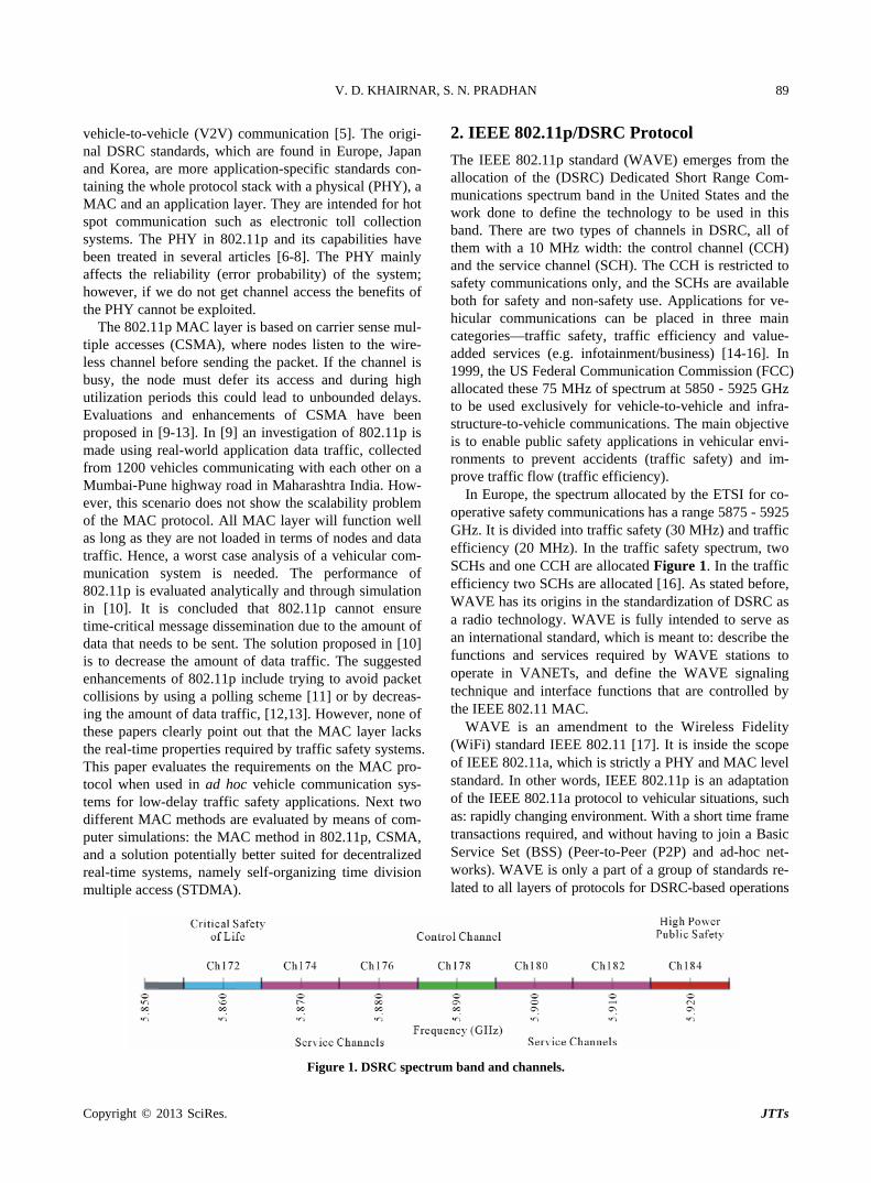
In Europe, the spectrum allocated by the ETSI for co- operative safety communications has a range 5875 - 5925 GHz. It is divided into traffic safety (30 MHz) and traffic efficiency (20 MHz). In the traffic safety spectrum, two SCHs and one CCH are allocated Figure 1. In the traffic efficiency two SCHs are allocated [16]. As stated before, WAVE has its origins in the standardization of DSRC as a radio technology. WAVE is fully intended to serve as an international standard, which is meant to: describe the functions and services required by WAVE stations to operate in VANETs, and define the WAVE signaling technique and interface functions that are controlled by the IEEE 802.11 MAC.
WAVE is an amendment to the Wireless Fidelity (WiFi) standard IEEE 802.11 [17]. It is inside the scope of IEEE 802.11a, which is strictly a PHY and MAC level standard. In other words, IEEE 802.11p is an adaptation of the IEEE 802.11a protocol to vehicular situations, such as: rapidly changing environment. With a short time frame transactions required, and without having to join a Basic Service Set (BSS) (Peer-to-Peer (P2P) and ad-hoc net- works). WAVE is only a part of a group of standards re- lated to all layers of protocols for DSRC-based operations
Figure 1. DSRC spectrum band and channels.
Copyright © 2013 SciRes. JTTs
V. D. KHAIRNAR, S. N. PRADHAN 90
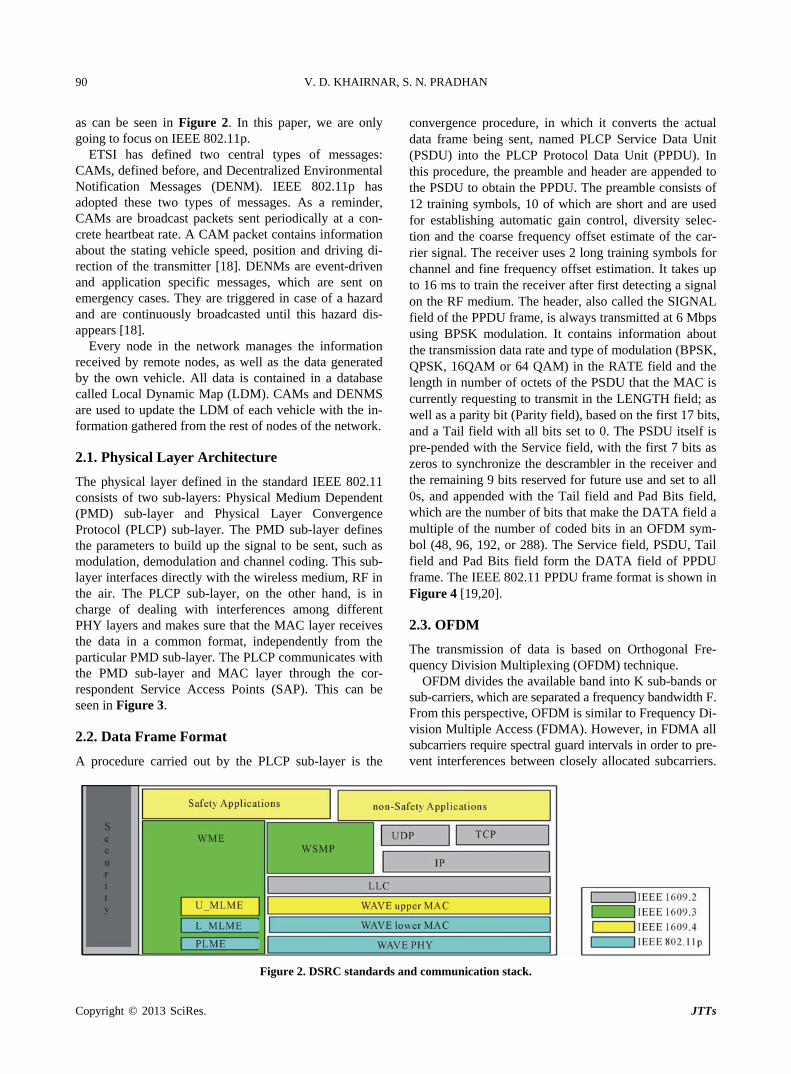
as can be seen in Figure 2. In this paper, we are only going to focus on IEEE 802.11p.
ETSI has defined two central types of messages: CAMs, defined before, and Decentralized Environmental Notification Messages (DENM). IEEE 802.11p has adopted these two types of messages. As a reminder, CAMs are broadcast packets sent periodically at a con- crete heartbeat rate. A CAM packet contains information about the stating vehicle speed, position and driving di- rection of the transmitter [18]. DENMs are event-driven and application specific messages, which are sent on emergency cases. They are triggered in case of a hazard and are continuously broadcasted until this hazard dis- appears [18].
Every node in the network manages the information received by remote nodes, as well as the data generated by the own vehicle. All data is contained in a database called Local Dynamic Map (LDM). CAMs and DENMS are used to update the LDM of each vehicle with the in- formation gathered from the rest of nodes of the network.
2.1. Physical Layer Architecture
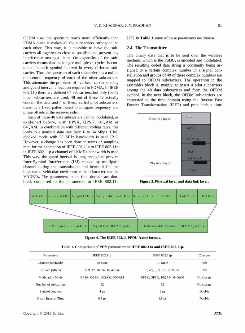
The physical layer defined in the standard IEEE 802.11 consists of two sub-layers: Physical Medium Dependent (PMD) sub-layer and Physical Layer Convergence Protocol (PLCP) sub-layer. The PMD sub-layer defines the parameters to build up the signal to be sent, such as modulation, demodulation and channel coding. This sub- layer interfaces directly with the wireless medium, RF in the air. The PLCP sub-layer, on the other hand, is in charge of dealing with interferences among different PHY layers and makes sure that the MAC layer receives the data in a common format, independently from the particular PMD sub-layer. The PLCP communicates with the PMD sub-layer and MAC layer through the cor- respondent Service Access Points (SAP). This can be seen in Figure 3.
2.2. Data Frame Format
A procedure carried out by the PLCP sub-layer is the
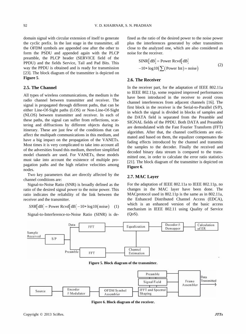
convergence procedure, in which it converts the actual data frame being sent, named PLCP Service Data Unit (PSDU) into the PLCP Protocol Data Unit (PPDU). In this procedure, the preamble and header are appended to the PSDU to obtain the PPDU. The preamble consists of 12 training symbols, 10 of which are short and are used for establishing automatic gain control, diversity selec- tion and the coarse frequency offset estimate of the car- rier signal. The receiver uses 2 long training symbols for channel and fine frequency offset estimation. It takes up to 16 ms to train the receiver after first detecting a signal on the RF medium. The header, also called the SIGNAL field of the PPDU frame, is always transmitted at 6 Mbps using BPSK modulation. It contains information about the transmission data rate and type of modulation (BPSK, QPSK, 16QAM or 64 QAM) in the RATE field and the length in number of octets of the PSDU that the MAC is currently requesting to transmit in the LENGTH field; as well as a parity bit (Parity field), based on the first 17 bits, and a Tail field with all bits set to 0. The PSDU itself is pre-pended with the Service field, with the first 7 bits as zeros to synchronize the descrambler in the receiver and the remaining 9 bits reserved for future use and set to all 0s, and appended with the Tail field and Pad Bits field, which are the number of bits that make the DATA field a multiple of the number of coded bits in an OFDM sym- bol (48, 96, 192, or 288). The Service field, PSDU, Tail field and Pad Bits field form the DATA field of PPDU frame. The IEEE 802.11 PPDU frame format is shown in Figure 4 [19,20].
2.3. OFDM
The transmission of data is based on Orthogonal Fre- quency Division Multiplexing (OFDM) technique.
OFDM divides the available band into K sub-bands or sub-carriers, which are separated a frequency bandwidth F. From this perspective, OFDM is similar to Frequency Di- vision Multiple Access (FDMA). However, in FDMA all subcarriers require spectral guard intervals in order to pre- vent interferences between closely allocated subcarriers.
Figure 2. DSRC standards and communication stack.
Copyright © 2013 SciRes. JTTs
V. D. KHAIRNAR, S. N. PRADHAN 91
OFDM uses the spectrum much more efficiently than FDMA since it makes all the subcarriers orthogonal to each other. This way, it is possible to have the sub- carriers all together as close as possible and prevent any interference amongst them. Orthogonality of the sub- carriers means that an integer multiple of cycles is con- tained in each symbol interval in every different sub- carrier. Thus the spectrum of each subcarrier has a null at the central frequency of each of the other subcarriers. This attenuates the problems of overhead carrier spacing and guard interval allocation required in FDMA. In IEEE 802.11p there are defined 64 subcarriers, but only the 52 inner subcarriers are used. 48 out of these 52 actually contain the data and 4 of them, called pilot subcarriers, transmit a fixed pattern used to mitigate frequency and phase offsets at the receiver side.
Each of these 48 data subcarriers can be modulated, as explained before, with BPSK, QPSK, 16QAM or 64QAM. In combination with different coding rates, this leads to a nominal data rate from 6 to 54 Mbps if full clocked mode with 20 MHz bandwidth is used [21]. However, a change has been done in terms of sampling rate, for the adaptation of IEEE 802.11a to IEEE 802.11p: in IEEE 802.11p a channel of 10 MHz bandwidth is used. This way, the guard interval is long enough to prevent Inter-Symbol Interference (ISI) caused by multipath channel during the transmission and hence it fits the high-speed vehicular environment that characterizes the VANETs. The parameters in the time domain are dou- bled, compared to the parameters in IEEE 802.11a
[17]. In Table 1 some of these parameters are shown.
2.4. The Transmitter
The binary data that is to be sent over the wireless medium, which is the PSDU, is encoded and modulated. The resulting coded data string is constantly being as- signed to a certain complex number in a signal con- stellation and groups of 48 of these complex numbers are mapped to OFDM subcarriers. The operation in the assembler block is, mainly, to insert 4 pilot subcarriers among the 48 data subcarriers and form the OFDM symbol. In the next block, the OFDM sub-carriers are converted to the time domain using the Inverse Fast Fourier Transformation (IFFT) and prep ends a time
Figure 3. Physical layer and data link layer.
Figure 4. The IEEE 802.11 PPDU frame format.
Table 1. Comparison of PHY parameters in IEEE 802.11a and IEEE 802.11p.
Parameters IEEE 802.11a IEEE 802.11p Changes
Channel bandwidth 20 MHz 10 MHz Half
Bit rate (Mbps) 6, 9, 12, 18, 24, 36, 48, 54 3, 4.5, 6, 9, 12, 18, 24, 27 Half
Modulation Mode BPSK, QPSK, 16QAM, 64QAM BPSK, QPSK, 16QAM, 64QAM No change
Number of subcarriers 52 52 No change
Symbol duration 4 µs 8 µs Double
Guard Interval Time 0.8 µs 1.6 µs Double
Copyright © 2013 SciRes. JTTs
V. D. KHAIRNAR, S. N. PRADHAN 92
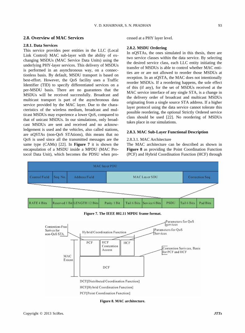
domain signal with circular extension of itself to generate the cyclic prefix. In the last stage in the transmitter, all the OFDM symbols are appended one after the other to form the PSDU and appended again with the PLCP preamble, the PLCP header (SERVICE field of the PPDU) and the fields Service, Tail and Pad Bits. This way the PPDU is obtained and is ready for transmission [23]. The block diagram of the transmitter is depicted on Figure 5.
2.5. The Channel
All types of wireless communications, the medium is the radio channel between transmitter and receiver. The signal is propagated through different paths, that can be either Line-Of-Sight paths (LOS) or Non-Line-Of-Sight (NLOS) between transmitter and receiver. In each of these paths, the signal can suffer from reflections, scat- tering and diffractions by different objects during its itinerary. These are just few of the conditions that can affect the multipath communications in this medium, and have a big impact on the propagation of the VANETs. Most times it is very complicated to take into account all of the adversities found this medium, therefore simplified model channels are used. For VANETs, these models must take into account the existence of multiple pro- pagation paths and the high relative velocities among nodes.
Two key parameters that are directly affected by the channel conditions are:
Signal-to-Noise Ratio (SNR) is broadly defined as the ratio of the desired signal power to the noise power. This ratio indicates the reliability of the link between the receiver and the transmitter.
dB Power Rcvd dB 10 log10 noiseSNR (1)
Signal-to-Interference-to-Noise Ratio (SINR) is de-
fined as the ratio of the desired power to the noise power plus the interferences generated by other transmitters close to the analyzed one, which are also considered as noise for the receiver.
SINR dB Power Rcvd dB
10 log10 Power Int noise
(2)
2.6. The Receiver
In the receiver part, for the adaptation of IEEE 802.11a to IEEE 802.11p, some required improved performances have been introduced in the receiver to avoid cross channel interferences from adjacent channels [16]. The first block in the receiver is the Serial-to-Parallel (S/P), in which the signal is divided in blocks of samples and the DATA field is separated from the Preamble and SIGNAL fields of the PPDU. Both DATA and Preamble are demodulated with the Fast Fourier Transform (FFT) algorithm. After that, the channel coefficients are esti- mated and based on them, the equalizer compensates the fading effects introduced by the channel and transmits the samples to the decoder. Finally the received and decoded binary data stream is compared to the trans- mitted one, in order to calculate the error ratio statistics [21]. The block diagram of the transmitter is depicted on Figure 6.
2.7. MAC Layer
For the adaptation of IEEE 802.11a to IEEE 802.11p, no changes in the MAC layer have been done. The MACprotocol used in 802.11p is the same as in 802.11a, the Enhanced Distributed Channel Access (EDCA), which is an enhanced version of the basic access mechanism in IEEE 802.11 using Quality of Service (QoS).
Figure 5. Block diagram of the transmitter.
Figure 6. Block diagram of the receiver.
Copyright © 2013 SciRes. JTTs
V. D. KHAIRNAR, S. N. PRADHAN 93
2.8. Overview of MAC Services
2.8.1. Data Services This service provides peer entities in the LLC (Local Link Control) MAC sub-layer with the ability of ex- changing MSDUs (MAC Service Data Units) using the underlying PHY-layer services. This delivery of MSDUs is performed in an asynchronous way, on a connec- tionless basis. By default, MSDU transport is based on best-effort. However, the QoS facility uses a Traffic Identifier (TID) to specify differentiated services on a per-MSDU basis. There are no guarantees that the MSDUs will be received successfully. Broadcast and multicast transport is part of the asynchronous data service provided by the MAC layer. Due to the chara- cteristics of the wireless medium, broadcast and mul- ticast MSDUs may experience a lower QoS, compared to that of unicast MSDUs. In our simulations, only broad- cast MSDUs are sent and received and no acknow- ledgement is used and the vehicles, also called stations, are nQSTAs (non-QoS STAtions), this means that no QoS is used since all the transmitted messages are the same type (CAMs) [22]. In Figure 7 it is shown the encapsulation of a MSDU inside a MPDU (MAC Pro- tocol Data Unit), which becomes the PDSU when pro-
cessed at a PHY layer level.
2.8.2. MSDU Ordering In nQSTAs, the ones simulated in this thesis, there are two service classes within the data service. By selecting the desired service class, each LLC entity initiating the transfer of MSDUs is able to control whether MAC enti- ties are or are not allowed to reorder those MSDUs at reception. In an nQSTA, the MAC does not intentionally reorder MSDUs. If a reordering happens, the sole effect of this (if any), for the set of MSDUs received at the MAC service interface of any single STA, is a change in the delivery order of broadcast and multicast MSDUs originating from a single source STA address. If a higher layer protocol using the data service cannot tolerate this possible reordering, the optional Strictly Ordered service class should be used [22]. No reordering of MSDUs takes place in our simulations.
2.8.3. MAC Sub-Layer Functional Description
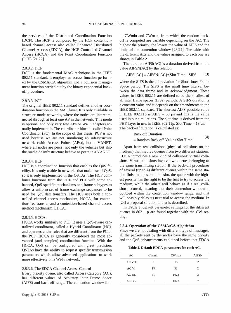
2.8.3.1. MAC Architecture The MAC architecture can be described as shown in Figure 8 as providing the Point Coordination Function (PCF) and Hybrid Coordination Function (HCF) through
Figure 7. The IEEE 802.11 MPDU frame format.
Figure 8. MAC architecture.
Copyright © 2013 SciRes. JTTs
V. D. KHAIRNAR, S. N. PRADHAN 94
the services of the Distributed Coordination Function
undamental MAC technique in the IEEE
EEE 802.11 standard defines another coor-
dination function that enables the QoS fa-
milarly to PCF. It uses a QoS-aware cen-
ntrol egory (AC),
its CWmin and CWmax, from which the random back- (DCF). The HCF is composed by the HCF contention- based channel access also called Enhanced Distributed Channel Access (EDCA), the HCF Controlled Channel Access (HCCA) and the Point Coordination Function (PCF) [21,22].
2.8.3.2. DCF DCF is the f802.11 standard. It employs an access function perform- ed by the CSMA/CA algorithm and a collision manage- ment function carried out by the binary exponential back- off procedure.
2.8.3.3. PCF The original Idination function in the MAC layer. It is only available in structure mode networks, where the nodes are intercom- nected through at least one AP in the network. This mode is optional and only very few APs or Wi-Fi adapters ac- tually implement it. The coordinator block is called Point Coordinator (PC). In the scope of this thesis, PCF is not used because we are not simulating an infrastructure network (with Access Points (APs)), but a VANET, where all nodes are peers: not only the vehicles but also the road-side infrastructure behave as peers in a VANET.
2.8.3.4. HCF HCF is a coorcility. It is only usable in networks that make use of QoS, so it is only implemented in the QSTAs. The HCF com- bines functions from the DCF and PCF with some en- hanced, QoS-specific mechanisms and frame subtypes to allow a uniform set of frame exchange sequences to be used for QoS data transfers. The HCF uses both a con- trolled channel access mechanism, HCCA, for conten- tion-free transfer and a contention-based channel access method mechanism, EDCA.
2.8.3.5. HCCA HCCA works sitralized coordinator, called a Hybrid Coordinator (HC), and operates under rules that are different from the PC of the PCF. HCCA is generally considered the most ad- vanced (and complex) coordination function. With the HCCA, QoS can be configured with great precision. QSTAs have the ability to request specific transmission parameters which allow advanced applications to work more effectively on a Wi-Fi network.
2.8.3.6. The EDCA Channel Access CoEvery priority queue, also called Access Cathas different values of Arbitrary Inter Frame Space (AIFS) and back-off range. The contention window lim-
off is computed are variable depending on the AC. The highest the priority, the lowest the value of AIFS and the limits of the contention window [23,24]. The table with the different ACs and the values assigned to each one are shown in Table 2.
The duration AIFS(AC) is a duration derived from the value AIFSN(AC) by the relation:
IFSN AC Slot Time SIFSAIFS AC A (3)
all time interval tween the data frame and its acknowledgmen
on the medium) that involve queues from two differeEDCA introduces a new kind of collisions: virtual colli- si
sent by the nodes have the same priority t EDCA
where the SIFS is the abbreviation for Short Inter-Frame Space period. The SIFS is the sm be-
t. These values in IEEE 802.11 are defined to be the smallest of all inter frame spaces (IFSs) periods. A SIFS duration is a constant value and it depends on the amendments to the IEEE 802.11 standard. The shortest AIFS possible value in IEEE 802.11p is AIFS = 58 µs and this is the value used in our simulations. The slot time is derived from the PHY layer in use: in IEEE 802.11p, Slot Time = 13 µs. The back-off duration is calculated as:
Back off Duration
Random Back off Value Slot Time (4)
Apart from real collisions (physical collisions nt stations,
ons. Virtual collisions involve two queues belonging to the same transmitting station. If the back-off procedures of several (up to 4) different queues within the same sta- tion finish at the same time slot, the queue with the high- est priority has the right to be the first to try to access the medium, while the others will behave as if a real colli- sion occurred, meaning that their contention window is doubled within the contention window range, and that will possibly delay its next trial to access the medium. In [24] a proposal solution to that is described.
In Table 3, default parameter settings for the different queues in 802.11p are found together with the CW set- ting.
2.8.4. Operation of the CSMA/CA Algorithm Since we are not dealing with different type of messages, all the packetsand the QoS enhancements explained before tha
Table 2. Default EDCA parameters for each AC.
AC CWmin CWmax AIFSN
AC VO 7 15 2
AC VI
31 1023
AC BK 31 1023 7
15 31 2
AC BE 3
Copyright © 2013 SciRes. JTTs
V. D. KHAIRNAR, S. N. PRADHAN 95
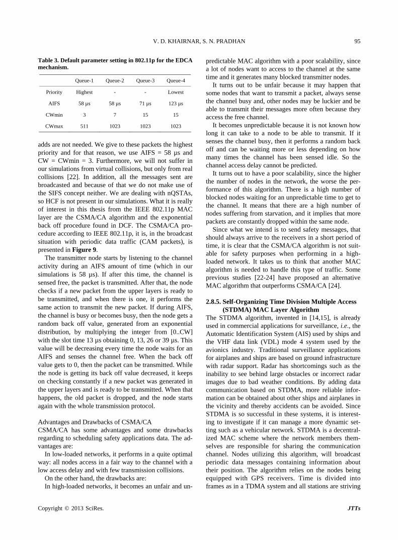
Table 3. Default parameter setting in 802.11p for the EDCA mech
Queue-1 Queue-2 Queue-3 Queue-4
anism.
Priority Highest - - Lowest
AIFS 58 µs 58 µs 71 µs 123 µs
CWmin 3
1023 1023 1023
7 15 15
CWmax 511
ad ot needed. We giv to these kets the hest pri d for that reason we use AI = 58 µs and CW min = 3. Furt re, w not in ur simulations from virtual collisions, but only from real
is transmitted. After that, the node ch
he ad- vantages are:
quite optimal
r hand, the drawbacks are:
e tim itter nodes.
ey ac
more or less depending on how m
time to get to th
h- lo
ready used in commercial applications for surveillance, i.e., the
the V used by the
ds are nority an
e ,
pacFS
hig
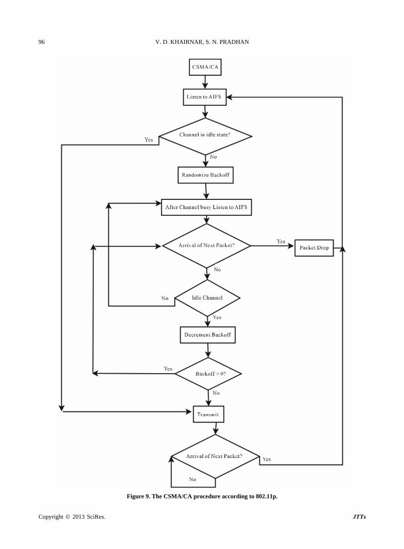
= CW hermo e will sufferocollisions [22]. In addition, all the messages sent are broadcasted and because of that we do not make use of the SIFS concept neither. We are dealing with nQSTAs, so HCF is not present in our simulations. What it is really of interest in this thesis from the IEEE 802.11p MAC layer are the CSMA/CA algorithm and the exponential back off procedure found in DCF. The CSMA/CA pro- cedure according to IEEE 802.11p, it is, in the broadcast situation with periodic data traffic (CAM packets), is presented in Figure 9.
The transmitter node starts by listening to the channel activity during an AIFS amount of time (which in our simulations is 58 µs). If after this time, the channel is sensed free, the packet
ecks if a new packet from the upper layers is ready to be transmitted, and when there is one, it performs the same action to transmit the new packet. If during AIFS, the channel is busy or becomes busy, then the node gets a random back off value, generated from an exponential distribution, by multiplying the integer from [0..CW] with the slot time 13 µs obtaining 0, 13, 26 or 39 µs. This value will be decreasing every time the node waits for an AIFS and senses the channel free. When the back off value gets to 0, then the packet can be transmitted. While the node is getting its back off value decreased, it keeps on checking constantly if a new packet was generated in the upper layers and is ready to be transmitted. When that happens, the old packet is dropped, and the node starts again with the whole transmission protocol.
Advantages and Drawbacks of CSMA/CA CSMA/CA has some advantages and some drawbacks regarding to scheduling safety applications data. T
In low-loaded networks, it performs in away: all nodes access in a fair way to the channel with a low access delay and with few transmission collisions.
On the otheIn high-loaded networks, it becomes an unfair and un-
predictable MAC algorithm with a poor scalability, since a lot of nodes want to access to the channel at the sam
e and it generates many blocked transmIt turns out to be unfair because it may happen that
some nodes that want to transmit a packet, always sense the channel busy and, other nodes may be luckier and be able to transmit their messages more often because th
cess the free channel. It becomes unpredictable because it is not known how
long it can take to a node to be able to transmit. If it senses the channel busy, then it performs a random back off and can be waiting
any times the channel has been sensed idle. So the channel access delay cannot be predicted.
It turns out to have a poor scalability, since the higher the number of nodes in the network, the worse the per- formance of this algorithm. There is a high number of blocked nodes waiting for an unpredictable
e channel. It means that there are a high number of nodes suffering from starvation, and it implies that more packets are constantly dropped within the same node.
Since what we intend is to send safety messages, that should always arrive to the receivers in a short period of time, it is clear that the CSMA/CA algorithm is not suit- able for safety purposes when performing in a hig
aded network. It takes us to think that another MAC algorithm is needed to handle this type of traffic. Some previous studies [22-24] have proposed an alternative MAC algorithm that outperforms CSMA/CA [24].
2.8.5. Self-Organizing Time Division Multiple Access (STDMA) MAC Layer Algorithm
The STDMA algorithm, invented in [14,15], is al
Automatic Identification System (AIS) used by ships andHF data link (VDL) mode 4 system
avionics industry. Traditional surveillance applications for airplanes and ships are based on ground infrastructure with radar support. Radar has shortcomings such as the inability to see behind large obstacles or incorrect radar images due to bad weather conditions. By adding data communication based on STDMA, more reliable infor- mation can be obtained about other ships and airplanes in the vicinity and thereby accidents can be avoided. Since STDMA is so successful in these systems, it is interest- ing to investigate if it can manage a more dynamic set- ting such as a vehicular network. STDMA is a decentral- ized MAC scheme where the network members them- selves are responsible for sharing the communication channel. Nodes utilizing this algorithm, will broadcast periodic data messages containing information about their position. The algorithm relies on the nodes being equipped with GPS receivers. Time is divided into frames as in a TDMA system and all stations are striving
Copyright © 2013 SciRes. JTTs
V. D. KHAIRNAR, S. N. PRADHAN
Copyright © 2013 SciRes. JTTs
96
Figure 9. The CSMA/CA procedure according to 802.11p.
V. D. KHAIRNAR, S. N. PRADHAN 97
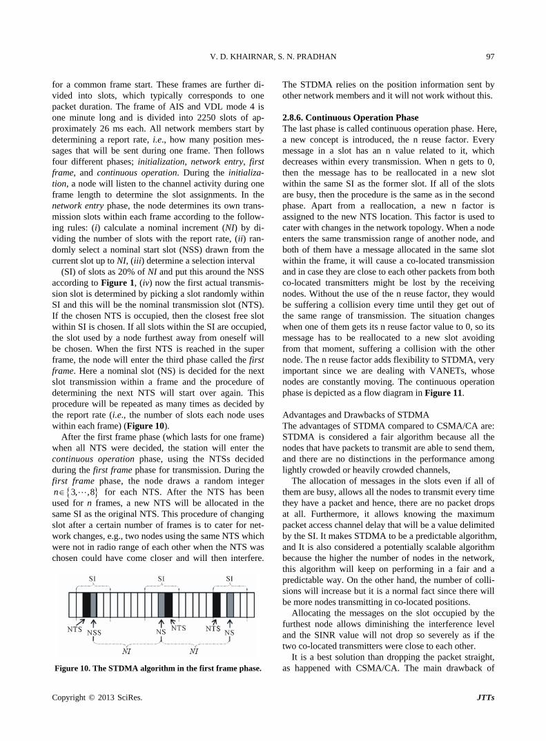
for a common frame start. These frames are further di- vided into slots, which typically corresponds to one packet duration. The frame of AIS and VDL mode 4 is one minute long and is divided into 2250 slots of ap- proximately 26 ms each. All network members start by determining a report rate, i.e., how many position mes- sages that will be sent during one frame. Then follows four different phases; initialization, network entry, first frame, and continuous operation. During the initializa- tion, a node will listen to the channel activity during one frame length to determine the slot assignments. In the network entry phase, the node determines its own trans- mission slots within each frame according to the follow- ing rules: (i) calculate a nominal increment (NI) by di- viding the number of slots with the report rate, (ii) ran- domly select a nominal start slot (NSS) drawn from the current slot up to NI, (iii) determine a selection interval
(SI) of slots as 20% of NI and put this around the NSS according to Figure 1, (iv) now the first actual transmis- sion slot is determined by picking a slot randomly within SI and this will be the nominal transmission slot (NTS). If the chosen NTS is occupied, then the closest free slot within SI is chosen. If all slots within the SI are occupied, the slot used by a node furthest away from oneself will be chosen. When the first NTS is reached in the super frame, the node will enter the third phase called the first frame. Here a nominal slot (NS) is decided for the next slot transmission within a frame and the procedure of determining the next NTS will start over again. This procedure will be repeated as many times as decided by the report rate (i.e., the number of slots each node uses within each frame) (Figure 10).
After the first frame phase (which lasts for one frame) when all NTS were decided, the station will enter the continuous operation phase, using the NTSs decided during the first frame phase for transmission. During the first frame phase, the node draws a random integer
for each NTS. After the NTS has been mes, a new NTS will be allocated in the
same SI as the original NTS. This procedure of changing slot after a certain number of frames is to cater for net- work changes, e.g., two nodes using the same NTS which were not in radio range of each other when the NTS was chosen could have come closer and will then interfere.
3, ,8n used for n fra
Figure 10. The STDMA algorithm in the first frame phase.
The STDMA relies on the position information sent by other network members and it will not work without this.
2.8.6. Continuous Operation Phase The last phase is called continuous operation phase. Here, a new concept is introduced, the n reuse factor. Every message in a slot has an n value related to it, which decreases within every transmission. When n gets to 0, then the message has to be reallocated in a new slot within the same SI as the former slot. If all of the slots are busy, then the procedure is the same as in the second phase. Apart from a reallocation, a new n factor is assigned to the new NTS location. This factor is used to cater with changes in the network topology. When a node enters the same transmission range of another node, and both of them have a message allocated in the same slot within the frame, it will cause a co-located transmission and in case they are close to each other packets from both co-located transmitters might be lost by the receiving nodes. Without the use of the n reuse factor, they would be suffering a collision every time until they get out of the same range of transmission. The situation changes when one of them gets its n reuse factor value to 0, so its message has to be reallocated to a new slot avoiding from that moment, suffering a collision with the other node. The n reuse factor adds flexibility to STDMA, very important since we are dealing with VANETs, whose nodes are constantly moving. The continuous operation phase is depicted as a flow diagram in Figure 11.
Advantages and Drawbacks of STDMA The advantages of STDMA compared to CSMA/CA are: STDMA is considered a fair algorithm because all the nodes that have packets to transmit are able to send them, and there are no distinctions in the performance among lightly crowded or heavily crowded channels,
The allocation of messages in the slots even if all of them are busy, allows all the nodes to transmit every time they have a packet and hence, there are no packet drops at all. Furthermore, it allows knowing the maximum packet access channel delay that will be a value delimited by the SI. It makes STDMA to be a predictable algorithm, and It is also considered a potentially scalable algorithm because the higher the number of nodes in the network, this algorithm will keep on performing in a fair and a predictable way. On the other hand, the number of colli- sions will increase but it is a normal fact since there will be more nodes transmitting in co-located positions.
Allocating the messages on the slot occupied by the furthest node allows diminishing the interference level and the SINR value will not drop so severely as if the two co-located transmitters were close to each other.
It is a best solution than dropping the packet straight, as happened with CSMA/CA. The main drawback of
Copyright © 2013 SciRes. JTTs

V. D. KHAIRNAR, S. N. PRADHAN 98
eration phase of STDMA.
saturated networks, the advantages of STDMA become clearer.
3. Simulations
M
Figure 11. The continuous op
A is the need of every STDMA node of relying on a positioning system. It adds a second actor for safety applications and another point susceptible to fail.
For low-loaded networks, it has been shown in previ- ous simulations [21,23,24] that both algorithms perform similarly, and even in some performance metrics such as the distance between concurrently transmitting nodes, STDMA outperforms CSMA/CA. For high-loaded or
STDM
any traffic safety systems will rely on vehicles pe- riodically broadcasting messages containing their current state (e.g., current location, speed, average speed, dis- tances travelled, total distance etc). We have developed a
Copyright © 2013 SciRes. JTTs
V. D. KHAIRNAR, S. N. PRADHAN 99
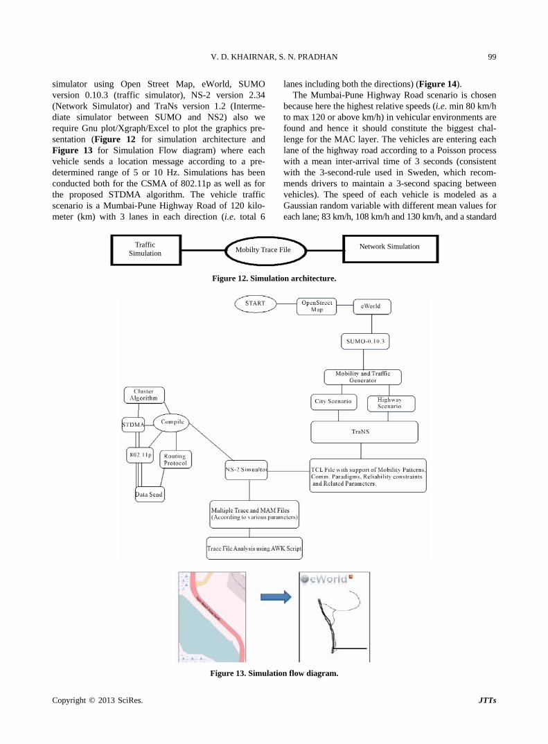
simulator using Open Street Map, eWorld, SUMO ve(Network Simulator) and TraNs version 1.2 (Interme- diate simulator between SUMO and NS2) also we require Gnu plot/Xgraph/Excel to plot the graphics pre- sentation (Figure 12 for simulation architecture and Figure 13 for Simulation Flow diagram) where each vehicle sends a location message according to a pre- determined range of 5 or 10 Hz. Simulations has been conducted both for the CSMA of 802.11p as well as for the proposed STDMA algorithm. The vehicle traffic scenario is a Mumbai-Pune Highway Road of 120 kilo- meter (km) with 3 lanes in each direction (i.e. total 6
he Mumbai-Pune Highway Road scenario is chosen because here the highest relative speeds (i.e. min 80 km/h to max 120 or above km/h) in vehicular environments are found and hence it should constitute the biggest chal- lenge for the MAC layer. The vehicles are entering each lane of the highway road according to a Poisson process with a mean inter-arrival time of 3 seconds (consistent with the 3-second-rule used in Sweden, which recom- mends drivers to maintain a 3-second spacing between vehicles). The speed of each vehicle is modeled as a Gaussian random variable with different mean values for each lane; 83 km/h, 108 km/h and 130 km/h, and a standard
rsion 0.10.3 (traffic simulator), NS-2 version 2.34 lanes including both the directions) (Figure 14).
T
Traffic Simulation Mobilty Trace File Network Simulation
Figure 12. Simulation architecture.
Figure 13. Simula tion flow diagram.
Copyright © 2013 SciRes. JTTs
V. D. KHAIRNAR, S. N. PRADHAN 100
deviation of 1 m/s. For simplicity we assume that no overtaking is possible and vehicles always remain in the same lane. There is no other data traffic in addition to the broadcast messages.
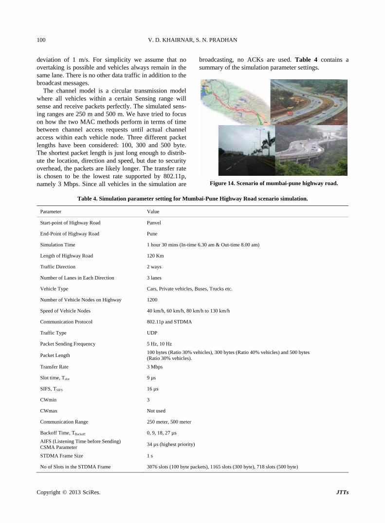
The channel model is a circular transmission model where all vehicles within a certain Sensing range will sense and receive packets perfectly. The simulated sens- ing ranges are 250 m and 500 m. We have tried to focus on how the two MAC methods perform in terms of time between channel access requests until actual channel access within each vehicle node. Three different packet lengths have been considered: 100, 300 and 500 byte. The shortest packet length is just long enough to distrib- ute the location, direction and speed, but due to security overhead, the packets are likely longer. The transfer rate is chosen to be the lowest rate supported by 802.11p,
broadcasting, no ACKs are used. Table 4 contains a summary of the simulation parameter settings.
n
amely 3 Mbps. Since all vehicles in the simulation are Figure 14. Scenario of mumbai-pune highway road.
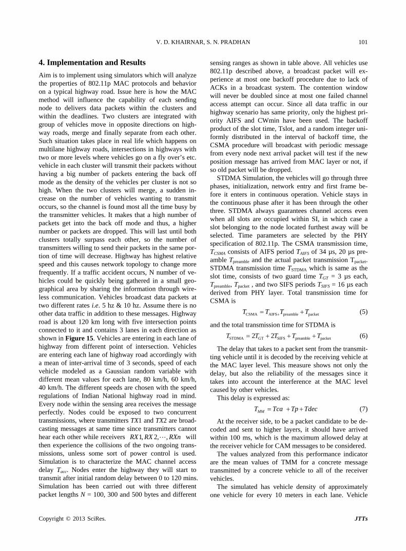
Table 4. Simulation parameter setting for Mumbai-Pune Highway Road scenario simulation.
Parameter Value
Start-point of Highway Road Panvel
End-Point of Highway Road Pune
Simulation Time 1 hour 30 mins (In-time 6.30 am & Out-time 8.00 am)
Length of Highway Road 120 Km
Traffic Direction 2 ways
Number of Lanes in Each Direction 3 lanes
Vehicle Type Cars, Private vehicles, Buses, Trucks etc.
Number of Vehicle Nodes on Highway 1200
Speed of Vehicle Nodes 40 km/h, 60 km/h, 80 km/h to 130 km/h
Communication Protocol 802.11p and STDMA
Traffic Type UDP
Packet Sending Frequency 5 Hz, 10 Hz
Packet Length 100 bytes (Ratio 30% vehicles), 300 bytes (Ratio 40% vehicles) and 500 bytes (Ratio 30% vehicles).
Transfer Rate 3 Mbps
Slot time, Tslot 9 µs
SIFS, TSIFS 16 µs
CWmin 3
CWmax Not used
Communication Range 250 meter, 500 meter
Backoff Time, TBackoff 0, 9, 18, 27 µs
AIFS (Listening Time before Sending) CSMA Parameter
34 µs (highest priority)
STDMA Frame Size 1 s
No of Slots in the STDMA Frame 3076 slots (100 byte packets), 1165 slots (300 byte), 718 slots (500 byte)
Copyright © 2013 SciRes. JTTs
V. D. KHAIRNAR, S. N. PRADHAN 101
4. Implementation and Results
Aim is to implement using simulators which will analyze the properties of 802.11p MAC protocols and behavior on a typical highway road. Issue here is how the MAC method will influence the capability of each sending node to delivers data packets within the clusters and within the deadlines. Two clusters are integrated with group of vehicles move in opposite directions on high-
ay roads, merge and finally separate fr
icles could be quickly being gathered in a small geo- graphical area less communication. Vehicles broadcast data packets at t nt rates i.e. 5 hz & 10 hz. Assume there is no o on to these mes ighway roa g with five inter oints c ins 3 lanes in e rection as s 15. Vehicles are enteringh nt point of interse ehicles are enteri of highway road acc ly with a arrival time of 3 seconds of each v an random le with diffe values for each lane, 80 k4 different speeds are chosenr ighway ind. E sensing area receivper d be exposed to twt ansmitters TX1 and c ages at same time since tran rs cannot hear each other while receivers will t lisions of the two ans- m ess some sort of power cSimulation is to characterize the MAC d odes enter the highway th start to t initial random delay betwee 120 mins. Sim s been carried out with ferent packet le hs N = 100, 300 and 500 bytes and different
sensing ranges as shown in table above. All vehicles use 802.11p described above, a broadcast packet will ex- perience at most one backoff procedure due to lack of ACKs in a broadcast system. The contention window will never be doubled since at most one failed channel access attempt can occur. Since all data traffic in our highway scenario has same priority, only the highest pri- ority AIFS and CWm have been used. The backoff
e slot, and a random integer uni- in the interval of backoff time, the
f the new position message has arrived from MAC layer or not, if so old packet will be dropped.
STDMA Simulation, the vehicles will go through three phases, initialization, network entry and first frame be- fore it enters in continuous operation. Vehicle stays in the continuous phase after it has been through the other three. STDMA always guarantees channel access even when all slots are occupied within SI, in which case a slot belonging to the node located furthest away will be selected. Time parameters are selected by the PHY specification of 802.11p. The CSMA transmission time, TCSMA consists of AIFS period TAIFS of 34 µs, 20 µs pre- amble Tpreamble and the actual packet transmission Tpacket
STDMA transmission time T which is same as thslot ch,
S = 16 µs each sion time for
CSMA is
w om each other. product of the slot timformly distributed
Such situation takes place in real life which happens on multilane highway roads, intersections in highways with two or more levels where vehicles go on a fly over’s etc. vehicle in each cluster will transmit their packets without having a big number of packets entering the back off mode as the density of the vehicles per cluster is not so high. When the two clusters will merge, a sudden in- crease on the number of vehicles wanting to transmit occurs, so the channel is found most all the time busy by the transmitter vehicles. It makes that a high number of packets get into the back off mode and thus, a higher number or packets are dropped. This will last until both clusters totally surpass each other, so the number of transmitters willing to send their packets in the same por- tion of time will decrease. Highway has highest relative speed and this causes network topology to change more frequently. If a traffic accident occurs, N number of ve- h
by sharing the information through wire- Tpreamble, Tpacket , and two SIFS periods TSIF
derived from PHY layer. Total transmis
wo differether data traffic in additi sages. H
d is about 120 km lononnected to it and conta
section pach di
hown in Figure in each lane of ighway from differe
ng each lane ction. V
ording mean of inter- , speedehicle modeled as a Gaussi variab
rent mean0 km/h. The
m/h, 60 km/h, with the speed
egulations of Indian National h road in mvery node within the
fectly. Nodes coules the message
o concurrent ransmissions, where tr TX2 are broad- asting mess smitte
1, 2, ,RX RX RXnhen experience the col ongoing trissions, unl ontrol is used.
channel access elay Tacc. N ey will ransmit after n 0 to
ulation hangt
three dif
in, T
CSMA procedure will broadcast with periodic message from every node next arrival packet will test i
. e STDMA
time, consists of two guard time TGT = 3 µs ea
CSMA AIFS preamble packet T T T T (5)
and the total transmission time for STDMA is
STDMA GT2 2T T TSIFS preamble packetT T (6)
The delay that takes to a packet sent from the transmit- ting vehicle until it is decoded by the receiving vehicle at the MAC layer level. This measure shows not only the delay, but also the reliability of the messages since it
count the interference at the MAC level r vehicles.
This delay is expressed as:
takes into accaused by othe
MMT Tca Tp Tdec (7)
At the receiver side, to be a packet candidate to be de- coded and sent to higher layers, it should have arrived within 100 ms, which is the maximum allowed delay at the receiver vehicle for CAM messages to be considered.
or are the mean values of TMM for a concrete message transmitted by a concrete vehicle to all of the receiver vehicles.
The simulated has vehicle density of approximately one vehicle for every 10 meters in each lane. Vehicle
The values analyzed from this performance indicat
Copyright © 2013 SciRes. JTTs
V. D. KHAIRNAR, S. N. PRADHAN 102
density is chosen to examine the scaling ance of the two MAC layers. Simulation has been carried out in SUMO and NS2 simulator with the parameters settings s ove for the highway 5 pa ets are sent 10 times nd th since this corre- s requirea ndle 70 nodes that are ommunica- tion ra her without packet co u-
are overloan range when the acket drops takes
perform
hown in the table ab scenario. When 00 bytes long ck per second ae nodes have a sensing range in 1 km
argest bandwidthponds to the l ments per unit rea. MAC can ha
nge of each ot in c
llisions. Simlation contains situations that ded and a node has 210 neighbors within communicatiorange is 1 km, and consequently some pplace.
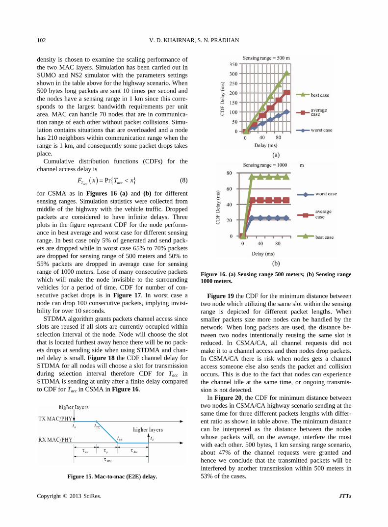
Cumulative distribution functions (CDFs) for the channel access delay is
PraccT accF x T x (8)
for CSMA as in Figures 16 (a) and (b) for different sensing ranges. Simulation statistics were collected from middle of the highway with the vehicle traffic. Dropped packets are considered to have infinite delays. Three plots in the figure represent CDF for the node perform- ance in best average and worst case for different sensing range. In best case only 5% of generated and send pack- ets are dropped while in worst case 65% to 70% packets are dropped for sensing range of 500 meters and 50% to 55% packets are dropped in average case for sensing range of 1000 meters. Lose of many consecutive packets which will make the node invisible to the surrounding vehicles for a period of time. CDF for number of con- secutive packet drops is in Figure 17. In worst case a node can drop 100 consecutive packets, implying invisi- bility for over 10 seconds.
STDMA algorithm grants packets channel access since slots are reused if all slots are currently occupied within selection interval of the node. Node will choose the slot that is located furthest away hence there will be no pack- ets drops at sending side when using STDMA and chan- nel delay is small. Figure 18 the CDF channel delay for STDMA for all nodes will choose a slot for transmission during selection interval therefore CDF for Tacc in STDMA is sending at unity after a finite delay compared to CDF for Tacc in CSMA in Figure 16.
(a)
(b)
Figure 16. (a) Sensing range 500 meters; (b) Sensing range 1000 meters.
Figure 19 the CDF for the minimum distance between two node which utilizing the same slot within the sensing range is depicted for different packet lengths. When smaller packets size more nodes can be handled by the network. When long packets are used, the distance be- tween two nodes intentionally reusing the same slot is reduced. In CSMA/CA, all channel requests did not make it to a channel access and then nodes drop packets. In CSMA/CA there is risk when nodes gets a channel access someone else also sends the packet and collision occurs. This is due to the fact that nodes can experience the channel idle at the same time, or ongoing transmis- sion is not detected.
In Figure 20, the CDF for minimum distance between two nodes in CSMA/CA highway scenario sending at the same time for three different packets lengths with differ- ent ratio as shown in table above. The minimum distance can be interpreted as the distance between the nodes whose packets will, on the average, interfere the most with each other. 500 bytes, 1 km sensing range scenario, about 47% of the channel requests were granted and hence we conclude that the transmitted packets will be interfered by another transmission with53% of the cases.
in 500 meters in Figure 15. Mac-to-mac (E2E) delay.
Copyright © 2013 SciRes. JTTs

V. D. KHAIRNAR, S. N. PRADHAN 103
Figure 17. Number of Packets dropped due to no channel access.
Figure 18. CDF for channel access delay in STDMA.
Figure 19. Utilizing the same time slot in STDMA to find minimum distance between two nodes.
5. Conclusion
In this paper we have analyzed how 802.11p and STDMA can be used for vehicle to vehicle performance
Figure 20. Sending at the same time in CSMa/CA using 500 bytes packets. 10 Hz, sensing range 1 km. for the safety application on highway. We have consider- ed different scenario and tested their performance and also compared their verage and worst s are less in percentage in best case when the packet size is small and sensing range can also cover more number or nodes to be broadcasted. It also possible to test the real imple- mentation using 802.11p/DSRC and STDMA and hope we can measure the same performance of DSRC and STDMA as a part of real implementation for future scope.
6. Acknowledgements
I would like to give my sincere thanks to my family members and friends who has helped me and gui ed me to complete my work and submit the paper on time.
REFERENCES [1] Intelligent Transportation Systems Joint Program Office,
“Reports from the Vehicle Infrastructure Integration Proof of Concept Project,” 2012. http://www.its.dot.gov/vii/index.htm
[2] C. M. Krishna and K. G. Shin, “Real-Time Systems,” McGraw-Hill, New York, 1997.
[3] IEEE 802.11 Working Group, “IEEE 802.11e Standard for Information Technology—Telecommunications and Information Exchange between Systems—Local and Met- ropolitan Area Networks—Specific Requirements Part 11: Wireless LAN Medium Access Control (MAC) and Physical Layer (PHY) S ications Amendment 8: Me- dium Access Control Quality of Service En-
m, A. Eskandarian and L. J. Hoffman, “Chal-
performance in form of best acase and identified the packets drop
d
pecif(MAC)
hancements,” 2005.
4] J. J. Blu[lenges of Intervehicle Ad Hoc Networks,” IEEE Transac- tions on Intelligent Transportation Systems, Vol. 5, No. 4, 2004, pp. 347-351.
Copyright © 2013 SciRes. JTTs
V. D. KHAIRNAR, S. N. PRADHAN
Copyright © 2013 SciRes. JTTs
104
[5] K. Bilstrup, “A Survey Regarding Wireless Communica- tion Standards Intended for a High-Speed Vehicle Envi- ronment,” Technical Report IDE 0712, Halmstad Univer- sity, Halmstad, 2007.
[6] L. Stibor, Y. Zang and H.-J. Reumermann, “Evaluation of Communication Distance of Broadcast Messages in a Ve- hicular Ad-Hoc Network Using IEEE 802.11p,” Pro- ceedings of IEEE Wireless Communications and Net- working Conference, Hong Kong, 11-15 March 2007, pp. 254-257. doi:10.1109/WCNC.2007.53
[7] M. Wellen, B. Westphal and P. Mähönen, “Performance Evaluation of IEEE 802.11-Based WLANs in Vehicular
dings of IEEE Intelligent Transportation Systems Conference, Toronto, 17-20 September 2006, pp. 355-362.
[10] S. Eichler, “Performance Evaluation of the IEEE 802.11p WAVE Communication Standard,” Proceedings of IEEE 66th Vehicular Technology Conference, Baltimore, 30 September-3 October 2007, pp. 2199-2203.
[11] N. Choi, et al., “A Solicitation-Based IEEE 802.11p MAC Protocol for Roadside to Vehicular Networks,” Proceedings of Workshops on Mobile Networking for Ve- hicular Environments, Anchorage, 11 May 2007, pp. 91- 96.
[12] C. Suthaputchakun and A. Ganz, “Priority Based Inter- Vehicle Communication in Vehicular Ad-Hoc Networks Using IEEE 802.11e,” Proceedings of IEEE 65th Vehicu- lar Technology Conference, Dublin, 22-25 April 2007, pp. 2595-2599.
[13] S. Shankar and A. Yedla, “MAC Layer Extensions for Improved QoS in 802.11 Based Vehicular Ad Hoc Net-
Vehicular Electronics and Safety, Beijing, 13-15 De- cember 2007, pp. 1-6.
[14] H. Lans, “Position Indicating System,” US Patent
5506587, 1996.
[15] R. Kjellberg, “Capacity and Throughput Using a Self Organized Time Division Multiple Access VHF Data Link in Surveillance Applications,” Master Thesis, Uni- versity of Stockholm, Stockholm, 1998.
[16] D. Jiang and L. Delgrossi, “IEEE 802.11p: Towards an International Standard for Wireless Access in Vehicular Environments,” IEEE Vehicular Technology Conference, Singapore, 11-14 May 2008, pp. 2036-2040.
[17] K. Sjöberg, “Standardization of Wireless Vehicular Com- munications within IEEE and ETSI,” IEEE VTS Work- shop on Wireless Vehicular Communications, Halmstad, 9 November 2011, 25p.
[18] A. Alonso, K. Sjöberg, E. Uhlemann, E. G. Ström and C. F. Mecklenbräuker, “Challenging Vehicular Scenarios for
ro- pean Cooperation in the Field of Scientific and Technical Research, Lund, 2011.
[19] P. Mackenzie, B. Miller, D. D. Coleman and D. A. Westcott, “CWAP Certified Wireless Analysis Profes-sional Official Study Guide,” John Wiley & Sons, Hobo-ken, 2011.
[20] V. Shivaldova, “Implementation of IEEE 802.11p Physi- cal Layer Model in SIMULINK,” Master’s Thesis, Vi- enna University of Technology, Vienna, 2010.
[21] M. El Masri, “IEEE 802.11e: The Problem of the Virtual Collision Management within EDCA,” Proceedings of 25th IEEE International Conference on Computer Com- munications, Barcelona, 23-29 April 2006, pp. 1-2.
[22] K. Bilstrup, E. Uhlemann, E. G. Ström and U. Bilstrup,
ireless Communica- orking, Vol. 2009, No. 13, 2009, Article
World Congress on ITS, 2009, 10p.
[24] K. S. Bilstrup, E. Uhlemann and E. G. Ström, “Scalability Issues for the MAC Methods STDMA and CSMA/CA of IEEE 802.11p When Used in VANETs,” IEEE Interna- tional Conference on Communications (ICC2010), Cape Town, 23-27 May 2010.
Scenarios,” Proceedings of IEEE 65th Vehicular Tech- nology Conference, Dublin, 22-25 April 2007, pp. 1167- 1171.
[8] W. Xiang, P. Richardson and J. Guo, “Introduction and Preliminary Experimental Results of Wireless Access for Vehicular Environments (WAVE) Systems,” Proceedings of 3rd Annual International Conference on Mobile and Ubiquitous Systems: Network and Services, San José, 17- 21 July 2006, pp. 1-8.
[9] F. Bai and H. Krishnan, “Reliability Analysis of DSRC Wireless Communication for Vehicle Safety Applica- tions,” Procee
works,” Proceedings of IEEE International Conference on
Self-Organizing Time Division Multiple Access,” Eu
“On the Ability of the 802.11p MAC Method and STDMA to Support Real-Time Vehicle-to-Vehicle Com- munication,” EURASIP Journal on Wtions and NetwNo. 5.
[23] K. Bilstrup, E. Uhlemann, E. G. Ström and U. Bilstrup, “On the Ability of the 802.11p and STDMA to Provide Predictable Channel Access,” Proceedings of the 16th