Assessment of the Performances of RANS Models for Simulating Swirling.pdf

General rights Copyright and moral rights for the publications made accessible in the public portal are retained by the authors and/or other copyright owners and it is a condition of accessing publications that users recognise and abide by the legal requirements associated with these rights.
Users may download and print one copy of any publication from the public portal for the purpose of private study or research.
You may not further distribute the material or use it for any profit-making activity or commercial gain
You may freely distribute the URL identifying the publication in the public portal If you believe that this document breaches copyright please contact us providing details, and we will remove access to the work immediately and investigate your claim.
Downloaded from orbit.dtu.dk on: Oct 30, 2021
Simulating the optical performances of the ATHENA X-ray telescope optics
Sironi, G.; Della Monica Ferreira, D.; Spiga, D.; Knudsen, E. Bergbäck; Bavdaz, M.; Bianucci, G.;Christensen, F. E.; Ferreira, I.; Fioretti, V.; Jegers, A. STotal number of authors:22
Published in:Space Telescopes and Instrumentation 2018: Ultraviolet to Gamma Ray
Link to article, DOI:10.1117/12.2315019
Publication date:2018
Document VersionPublisher's PDF, also known as Version of record
Link back to DTU Orbit
Citation (APA):Sironi, G., Della Monica Ferreira, D., Spiga, D., Knudsen, E. B., Bavdaz, M., Bianucci, G., Christensen, F. E.,Ferreira, I., Fioretti, V., Jegers, A. S., Lotti, S., Macculi, C., Marioni, F., Massahi, S., Molendi, S., Moretti, A.,Pareschi, G., Shortt, B., Tagliaferri, G., ... Wille, E. (2018). Simulating the optical performances of the ATHENAX-ray telescope optics. In J-W. A. den Herder, S. Nikzad, & K. Nakazawa (Eds.), Space Telescopes andInstrumentation 2018: Ultraviolet to Gamma Ray (Vol. 10699). [106993N] SPIE - International Society for OpticalEngineering. https://doi.org/10.1117/12.2315019

PROCEEDINGS OF SPIE
SPIEDigitalLibrary.org/conference-proceedings-of-spie
Simulating the optical performancesof the ATHENA x-ray telescope optics
Giorgia Sironi, Daniele Spiga, Desiree Della MonicaFerreira, Ivo Ferreira, Marcos Bavdaz, et al.
Giorgia Sironi, Daniele Spiga, Desiree Della Monica Ferreira, Ivo Ferreira,Marcos Bavdaz, Erik Bergback Knudsen, Giovanni Bianucci, Finn ErlandChristensen, Maximilien Collon, Fabio Marioni, Giovanni Pareschi, Arne 'SJagers, Bianca Salmaso, Brian Shortt, Gianpiero Tagliaferri, GiuseppeVacanti, Paolo Conconi, Giuseppe Valsecchi, Niels J. Westergaard, EricWille, Sonny Massahi, "Simulating the optical performances of the ATHENAx-ray telescope optics," Proc. SPIE 10699, Space Telescopes andInstrumentation 2018: Ultraviolet to Gamma Ray, 106993N (20 August 2018);doi: 10.1117/12.2315019
Event: SPIE Astronomical Telescopes + Instrumentation, 2018, Austin, Texas,United States
Downloaded From: https://www.spiedigitallibrary.org/conference-proceedings-of-spie on 1/8/2019 Terms of Use: https://www.spiedigitallibrary.org/terms-of-use

Simulating the optical performances of the ATHENA X-raytelescope optics
G. Sironi,a D. Della Monica Ferreira,b D. Spiga,a,c E. Bergback Knudsen,b M. Bavdaz,d
G. Bianucci,e F. E. Christensen,b I. Ferreira,d V. Fioretti,f A. S Jegers,b S. Lotti,h C. Macculi,h
F. Marioni,e S. Massahi,b S. Molendi,g A. Moretti,a G. Pareschi,a B. Shortt,d G. Tagliaferri,a
G. Valsecchi,e N.J. Westergaard,b E. Wille,d
aINAF - Brera Astronomical Observatory, Via Bianchi 46, 23807 Merate, ItalybDTU Space, Techn. Univ. of Denmark, Elektrovej b. 327, 2800 Kgs. Lyngby, DenmarkcSLAC National Accelerator Laboratory, 2575 Sand Hill Road, 94025 Menlo Park, USAdEuropean Space Agency, ESTEC, Keplerlaan 1, 2201 AZ Noordwjik, The Netherlands
eMedia Lario s.r.l., loc. Pascolo, 23842 Bosisio Parini, ItalyfINAF - IASF Bologna, Via Gobetti 101, 40129 Bologna, Italy
gINAF - IASF Milano, Via Bassini 15, 20133 Milano, ItalyhINAF - IAPS, Via Fosso del Cavaliere 100, 00133 Roma, Italy
ABSTRACT
The ATHENA (Advanced Telescope for High Energy Astrophysics) X-ray observatory is an ESA-selected L2class mission. In the proposed configuration, the optical assembly has a diameter of 2.2 m with an effective areaof 1.4 m2 at 1 keV, 0.25 m2 at 6 keV, and requires an angular resolution of 5 arcsec. To meet the requirementsof effective area and angular resolution, the technology of Silicon Pore Optics (SPO) was selected for the opticsimplementation. The ATHENA’s optic assembly requires hundreds of SPOs mirror modules (MMs), obtainedby stacking wedged and ribbed silicon wafer plates onto silicon mandrels to form the Wolter-I configuration.Different factors can contribute to limit the imaging performances of SPOs, such as i) diffraction through thepore apertures, ii) plate deformations due to fabrication errors and surface roughness, iii) alignment errors amongplates in an MM, and iv) co-focality errors within the MMs assembly. In order to determine the fabricationand assembling tolerances, the impact of these contributions needs to be assessed prior to manufacturing. Aset of simulation tools responding to this need was developed in the framework of the ESA-financed projectsSIMPOSIuM and ASPHEA. In this paper, we present the performance simulation obtained for the recently-proposed ATHENA configuration in terms of effective area, and we provide a simulation of the diffractive effectsin a pair of SPO MMs. Finally, we present an updated sizing of magnetic diverter (a Halbach array) and themagnetic fields levels that can be reached in order to deviate the most energetic protons out of the detectorfield.
Keywords: ATHENA, Silicon Pore Optics, optical design, simulation, alignment, diffraction
1. INTRODUCTION
The ATHENA X-ray observatory1 is an ESA large mission selected in the Cosmic Vision plan. The missionis planned to be launched to L2 in 2028. The proposed optical module of ATHENA consists of a single X-raytelescope with an effective area of about 1.4 m2 at 1.0 keV and 0.25 m2 at 6 keV, focal length of 12 m, andangular resolution of 5 arcsec.
To realize such a large aperture X-ray telescope, a technology based on Silicon Pore Optics (SPO) was selected.SPOs were developed in ESTEC since 2004 and relies on shaping Silicon plates to the desired optical profile.3
In summary, the manufacturing process consists of stacking doubly-side polished silicon wafers that have beenwedged and grooved. The adhesion of the plates is ensured by molecular Van der Waals interactions between
e-mail: [email protected], Telephone: +39-02-72320468
Space Telescopes and Instrumentation 2018: Ultraviolet to Gamma Ray, edited by Jan-Willem A. den Herder,Shouleh Nikzad, Kazuhiro Nakazawa, Proc. of SPIE Vol. 10699, 106993N · © 2018 SPIE
CCC code: 0277-786X/18/$18 · doi: 10.1117/12.2315019
Proc. of SPIE Vol. 10699 106993N-1Downloaded From: https://www.spiedigitallibrary.org/conference-proceedings-of-spie on 1/8/2019Terms of Use: https://www.spiedigitallibrary.org/terms-of-use

:.. ..... :,',.o,``*S,$ ,cc00.OMIT* ,**,%
1MMqÿ,ÌLÌ*::ii:t i: .iN/1111111114ii: :ii1111111111111111/i ::::1111111111111L4V. :iWiIIIp11111ï i...MvI1p11/p.m
5 :i i1iS,**I*Ì0i, jII: : i ¡ #j IiI1. ¡,:
Ìi=i.i .
1000
500
0
-1000
-1000 -500xwm>
500 1000
Figure 1. Left: A Wolter-I SPOs mirror module (image credits: ESA). The MM is realized as a double stack of 34 platesassembled in Wolter-I configuration. Right: Graphic representation of the MMs positions in the ATHENA telescope. TheMMs are organized in 15 rows with hexagonal symmetry.
the two silicon oxide surfaces, when they come into contact. The shaping of the plates is defined by the firstlayer assembled, formed on a silicon mandrel with either parabolic (primary) or hyperbolic (secondary) shape,reconstructing, e.g., the widespread Wolter-I configuration.2 Each MM is obtained4 assembling the two shapedstacks, each composed by two sections of 34 layers: moreover, to simplify the final population of modules intothe ATHENA optics structure, each MM includes two primary-secondary systems, operating in parallel. Thetypical height of a pore is of 0.606 mm, and its width is 0.83 mm (Figure 1-left). Considering the silicon platedimensions and the process characteristics, the MMs dimensional feasibility limit was set at about 100 mm. Thismeans that to populate the full telescope area a large number of MMs is required. In the configuration proposedby ESA (hereafter named configuration 3), the MMs are organized in 15 rows within six identical petals as inFigure 1-right, for a total of 678 units (Table 1).
The number of MMs to be produced is very large, but the SPOs technological solution offers great advantagesfor the realization of the optical module. They are:
• The replica process: just like nickel electroforming, the SPOs technology concentrates the efforts on themandrel in order to improve the mirror quality. This means that time and costs for the shaping do notincrease in proportion with the number of optical modules: they have to be allocated only once to producethe mandrel for each ring, instead of once per mirror like in the direct polishing technique. This solutionhas a strategic impact for mass production.
• The quality of the initial surfaces: just like thin glass foils, silicon plates are available on semiconductormarkets at affordable costs with intrinsic low roughness. This avoids the iterative fabrication of super-polished optical surfaces required by direct polishing (for mirrors) and nickel electroforming (for mandrels).
• Physical characteristics of silicon: monocrystalline silicon has very high thermal conductivity, which makesit suitable to minimize the thermal gradients and the consequent thermal distortions.
The development of the SPOs technology also poses challenging aspects, which are being currently assessed:
• The approximation in the design: each plate in a MM does not come into contact with a mandrel with adesignated shape when its shape is frozen into the stack: it is, rather replicated from the previous layer, withthe addition of a wedge. Hence, it is not immediately ensured that the optical surfaces be representing thedesired focusing optical shape. This approximation requires a considerable effort in terms of finite elementanalysis and a careful integration process in order to avoid accumulation of errors in the stack.
Proc. of SPIE Vol. 10699 106993N-2Downloaded From: https://www.spiedigitallibrary.org/conference-proceedings-of-spie on 1/8/2019Terms of Use: https://www.spiedigitallibrary.org/terms-of-use

Table 1. ATHENA’s configuration 3 parameters. MMs are organized on 15 rows with hexagonal symmetry. The radiusof the central plate is reported below. The width of the MMs was defined considering the symmetry and the feasibilitylimit of the plates. The length of the MMs was defined to make each module self-baffling.
Row #MM Radius [m] Width [mm] Lenght [mm]
1 30 0.286 37.096 101.504
2 30 0.348 50.158 83.388
3 36 0.411 49.838 70.762
4 42 0.473 49.613 61.46
5 30 0.535 89.363 54.321
6 36 0.597 82.476 48.671
7 42 0.659 77.571 44.087
8 42 0.722 86.892 40.294
9 48 0.784 82.053 37.101
10 48 0.846 90.205 34.383
11 54 0.908 85.538 32.036
12 54 0.970 92.782 29.99
13 60 1.032 88.326 28.191
14 60 1.095 94.845 26.597
15 66 1.157 90.608 25.175
• The effects on reflecting coating: in the originally proposed design, the baseline for the MMs coating wasan Ir/B4C bilayer,5 selected to optimize the effective area. Experimental tests of the coating performanceperformed at DTU Space have shown instability of the B4C coating, and incompatibility with the industrialprocesses involved in the production of SPO mirror modules.6 Silicon carbide (SiC) is recommended asreplacement for B4C. For the configuration 3 the proposed coating baseline is Ir/SiC.5,6
• The complex integration of the mirror assembly: considering the number of involved MMs, the misalignmentcontribution to be allocated in the error budget to the integration process should be carefully studied.
• The small size of pores: the pore structure generates a situation analogous to classical nested shell configu-ration, with reduced spacing in both directions (radial and azimuthal). This means that off-axis obstructionand stray-light modeling cannot be neglected. In addition, the pores are not so small to cause relevantdiffraction effects in X-rays, but the diffraction contribution would be dominant in UV light. As UV opticalbenches are envisaged to perform the mirror module alignment in the assembly, the impact of aperturediffraction on the MMs alignment performances should be accurately assessed.
In this paper we discuss the latest results of a parallel set of studies, financed by ESA, to support the designand the development of the ATHENA optical module. SIMPOSiuM (SIMulation of Pore OpticS and Modeling)is a collaboration between the Brera Italian National Institute for Astrophysics (INAF-OAB) and the NationalSpace Institute at the Technical University of Denmark (DTU Space) to develop software tools to simulate theoptical performances of ATHENA. Results from the collaboration were already presented in previous papers.7,8
Here we report the latest results on the simulations of ATHENA configuration 3. ASPHEA (Alignment of SiliconPore Optics for Height Energy Astrophysics) is a project led by Media Lario, involving INAF-OAB in the co-focality and diffraction simulation of MMs aligned on an UV bench. Results of this project were reported inprevious works.7–9 Here we report the work obtained for the case of two MMs with alignment simulated at anX-ray test facility with source at finite distance, the PANTER facility of MPE.10
Proc. of SPIE Vol. 10699 106993N-3Downloaded From: https://www.spiedigitallibrary.org/conference-proceedings-of-spie on 1/8/2019Terms of Use: https://www.spiedigitallibrary.org/terms-of-use

Central plate
Da = 0R /4f
+1/ +3 -1 / +1
Reflective surfaces/ +-
ilj3Figure 2. Different plate stacking in an SPO module, in radial section. Left: the +1/+3 wedge configuration requiresmanufacturing two different kinds of wedged plates. Center: the -1/+1 wedge configuration is obtained producing Siliconplates with the same wedge angle. Right: with respect to the +1/+3 wedge, the angle variation in the -1/+1 wedgeconfiguration introduces an apparent source divergence δn = 2n∆α for the n-th plate, counted from the central one.
2. EFFECTIVE AREA SIMULATION
The effective area of ATHENA can be calculated by means of the IDL code presented in previous papers.7,8 Thecode is based on the analytical computation of the illuminated area of each pore, extended to the full opticalsystem. The code takes the following input information:
• Wolter or Wolter-Schwarzschild design: the intersection plane of different radially-distributed MMs islocated at the same distance from the focal plane, along the axis or along the rays, respectively.
• -1/+1 or +1/+3 wedge configuration: in the Wolter-I design, the incidence angle of the rays on the reflectingsurfaces should increase by ∆α = ∆R/4f on the primary mirror and by 3∆α on the secondary one. Forfaithfully representing the Wolter-I configuration, the primary stacks should have a wedge angle ∆α, whilethe secondary stacks should have a triple wedging (+1/+3). To simplify the manufacturing, however, a-1/+1 configuration was proposed. This solution foresees the only use of ∆α-wedged plates mounted inopposite directions to maintain the nominal angular difference between the two reflecting surfaces (Fig. 2).The decrease of effective area due to a +1/-1 wedge configuration is equivalent to a small off-axis effect,and was evaluated to be within 2%. Such value is acceptable, when compared to the relevant processsimplification enabled by a single wedge manufacturing throughout the entire stack. We note that, even ifeach MM is composed by two primary+secondary parallel stacks, each individual stack has its central plateat the nominal angle. This was accounted for in the computation and contributed to reduce the effectivearea loss to the mentioned 2% level.
• Variable filling factor (FF): ATHENA MMs are designed to be self-baffling. This means that the lengthof each MM is defined to make the maximum radius of a plate correspond to the inner radius of the nextone (FF=1). This solution maximizes the effective area on-axis, but reduces the telescope field of view. Inthe case of SPOs technology, an approximation is intrinsic to the FF definition: all the plates composing aMM have the same length, but they are wedged to change the incidence angle, so it is possible to preciselyassign the desired FF only to the central plate in each stack. Outer and inner plates would have FF<1and FF>1, respectively.
• Variable source off-axis angle: the code allows to compute the effective area also for off-axis sources. Theoff-axis angle increases the obscuration of the pores and causes a major effective area decrease.
In Figure 3, top panel, we report the effective area computed for ATHENA’s configuration 3 (Tab. 1). Theeffective area computation was performed for Wolter I design, -1/+1 wedging configuration and FF=1. The
Proc. of SPIE Vol. 10699 106993N-4Downloaded From: https://www.spiedigitallibrary.org/conference-proceedings-of-spie on 1/8/2019Terms of Use: https://www.spiedigitallibrary.org/terms-of-use

e ro2.0
1.8- Configuration- Configuration
3, Ir +B4C3, Ir +SiC
1.6 - - Configuration 3, Ir
1.4E
1.2
1.0
0.8
0.6I-
0.4
0.2
0.003 4 5 6 7 8 9
Energy (keV)10
2.0
1.8
1.6
1.4
1.2
1.0
0.8
n6,
- Configuration 3, Ir +B4C- Configuration 3, Ir +SIC- Configuration 3, Ir
E
ó
0.4
2.0
1.8
1.6
1.4
1.2
1.0
0.8
nFi
0.2
- Configuration 3, Ir +B4C- Configuration 3, Ir +SIC- Configuration 3, Ir
0.05
Energy (keV)10
computation was repeated for three cases of optimized reflecting coatings.6 In Fig. 3, central and bottom panelswe report the results of the same computation for the cases of a 10 arcmin and 20 arcmin off-axis source. Theeffective area values obtained at 1 keV and 6 keV are reported in Tab. 2 for reference.
Figure 3. Energy-dependent Effective Area of ATHENA, configuration 3, as computed for three different coatings. The oldconfiguration coating baseline Ir/B4C (red curve), the new coating baseline Ir/SiC (green curve), and a plain Ir coating(blue curve) are shown. Top panel: results for an on-axis source. Central panel: results for a 10 arcmin off-axis source.Bottom panel: results for a 20 arcmin off-axis source.
Proc. of SPIE Vol. 10699 106993N-5Downloaded From: https://www.spiedigitallibrary.org/conference-proceedings-of-spie on 1/8/2019Terms of Use: https://www.spiedigitallibrary.org/terms-of-use
loam. 1 keV. exitvvs$_ ,
Ativvs' -:+
14, ae 9a, =aJIII wi11sM11 iR111MA1111 ' -}M.IRIRLI f111
WWI
*tia: 47,..IAV"_-z: 70
10am 10 keV exit
it-, ........
I
:i.+' ';?;
_v__w
sNN
IrW
ilM1010111IIM
:ae,4.0.11.1012111.
FI
SYs:pn
.rg
ga
srxx:ss
Table 2. Effective areas computed for ATHENA configuration 3 at 1 keV and 6 keV, for different off-axis angles.
Aeff@1 keV [m2] Aeff@6 keV [m2]Off-axis angle 0 arcmin 10 arcmin 20 arcmin 0 arcmin 10 arcmin 20 arcminIr/B4C 1.474 0.902 0.469 0.242 0.080 0.011Ir/SiC 1.399 0.854 0.443 0.238 0.077 0.010Ir 1.193 0.720 0.369 0.238 0.081 0.012
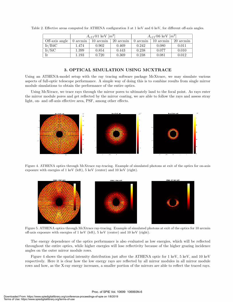
3. OPTICAL SIMULATION USING MCXTRACE
Using an ATHENA-model setup with the ray tracing software package McXtrace, we may simulate variousaspects of full-optic telescope performance. A simple way of doing this is to combine results from single mirrormodule simulations to obtain the performance of the entire optics.
Using McXtrace, we trace rays through the mirror pores to ultimately land to the focal point. As rays enterthe mirror module pores and get reflected by the mirror coating, we are able to follow the rays and assess straylight, on- and off-axis effective area, PSF, among other effects.
Figure 4. ATHENA optics through McXtrace ray-tracing. Example of simulated photons at exit of the optics for on-axisexposure with energies of 1 keV (left), 5 keV (center) and 10 keV (right).
Figure 5. ATHENA optics through McXtrace ray-tracing. Example of simulated photons at exit of the optics for 10 arcminoff-axis exposure with energies of 1 keV (left), 5 keV (center) and 10 keV (right).
The energy dependence of the optics performance is also evaluated as low energies, which will be reflectedthroughout the entire optics, while higher energies will lose reflectivity because of the higher grazing incidenceangles on the outer mirror module rows.
Figure 4 shows the spatial intensity distribution just after the ATHENA optic for 1 keV, 5 keV, and 10 keVrespectively. Here it is clear how the low energy rays are reflected by all mirror modules in all mirror modulerows and how, as the X-ray energy increases, a smaller portion of the mirrors are able to reflect the traced rays.
Proc. of SPIE Vol. 10699 106993N-6Downloaded From: https://www.spiedigitallibrary.org/conference-proceedings-of-spie on 1/8/2019Terms of Use: https://www.spiedigitallibrary.org/terms-of-use

: ;;8521: :;:=_?`s2?::;_:::;:.:?2E:E:sE
In much the same manner we can evaluate off-axis performance. Instead of having rays parallel to the opticalaxis impinge on the mirror modules, we let the rays come from an arbitrary angle. We show an example of theoff-axis simulation in Fig. 5 for the case of 10 arcmin off-axis angle around the horizontal axis. Also here, theenergy dependence in the reflection of rays is evident, illustrating the kind of losses that can be expected as afunction of the X-ray energy and the off-axis angle.
4. DIFFRACTION EFFECT OF MULTIPLE MIRROR MODULES
Due to the large number of modules to be aligned, a non-negligible contribution to the angular resolution errorbudget has to be allocated to MMs integration. The geometrical misalignment of the MMs can be easily managedby McXtrace. However, the adoption of SPOs technology requires a deeper analysis of the diffraction effect dueto the pore intrinsic high obstruction. This effect does not relevantly affect the X-ray angular resolution, whichwill be dominated by the plates shape errors, but it is quite strong in UV. Considering the case of the UVtest facilities adopted for the MMs alignment during integration process, the simulation of diffractive effects isdefinitely relevant to ATHENA.
Usually, the effects of profile error and diffraction are faced with separate simulation tools: on one side, ageometrical ray-tracing is used to simulate the optical quality degradation due to surface shape error; on theother hand, the sole aperture diffraction can be simulated by means of the Fresnel integrals. The main problemin this approach is that the transition region between the two phenomena is extended, and a cut-off value of λis impossible to set in general.11
A conclusive solution is to simulate the whole system by means of physical optics. The treatment of thediffraction of SPOs and the introduced approximations were already been discussed in a previous paper.7 Adirect comparison of the performed simulations with the experimental observed diffraction images was possibleat Media Lario UV (218 nm) optical bench9 and provided a successful validation of the method. Finally, also theinvariance of the PSF centroids positions of X-ray and UV images, even in presence of profiles longitudinal errors,was already presented one year ago.8 That confirmed that an integration process based on UV illumination iswell suitable for SPOs to achieve the requested alignment accuracy.
Here, we show that the adoption of a light source of finite dimensions does not affect the alignment of twoco-focal MMs. A simulation was performed modeling the Complex Pupil Function (CPF) of two flawless WolterI MMs (Fig. 6). The MMs where represented as two 42 mm illuminated regions separated by a dark area ofequal dimension. The radial distance of the central plate of the MMs is 737 mm and the pore dimensions are0.606 mm by 0.83 mm with rib thickness of 0.17 mm. The variable shade of red in Fig. 6 represent the opticalpath distance variation through the layers, increasing with the plate radius. This simulation reproduces a realalignment test performed at PANTER.9
Figure 6. CPF model used to simulate the co-focality of two separated MMs. Two MMs are considered separated by adark area, the variable shade of red represent the optical path distance variation through the layers.
Proc. of SPIE Vol. 10699 106993N-7Downloaded From: https://www.spiedigitallibrary.org/conference-proceedings-of-spie on 1/8/2019Terms of Use: https://www.spiedigitallibrary.org/terms-of-use
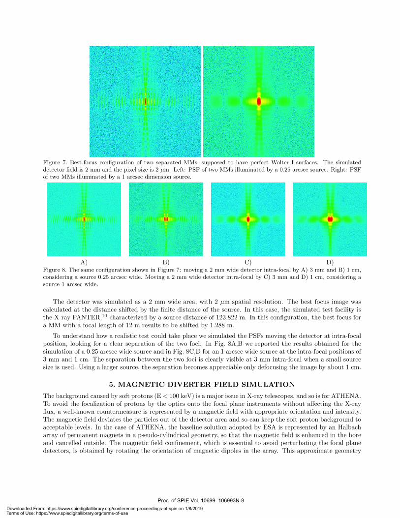
Figure 7. Best-focus configuration of two separated MMs, supposed to have perfect Wolter I surfaces. The simulateddetector field is 2 mm and the pixel size is 2 µm. Left: PSF of two MMs illuminated by a 0.25 arcsec source. Right: PSFof two MMs illuminated by a 1 arcsec dimension source.
A) B) C) D)Figure 8. The same configuration shown in Figure 7: moving a 2 mm wide detector intra-focal by A) 3 mm and B) 1 cm,considering a source 0.25 arcsec wide. Moving a 2 mm wide detector intra-focal by C) 3 mm and D) 1 cm, considering asource 1 arcsec wide.
The detector was simulated as a 2 mm wide area, with 2 µm spatial resolution. The best focus image wascalculated at the distance shifted by the finite distance of the source. In this case, the simulated test facility isthe X-ray PANTER,10 characterized by a source distance of 123.822 m. In this configuration, the best focus fora MM with a focal length of 12 m results to be shifted by 1.288 m.
To understand how a realistic test could take place we simulated the PSFs moving the detector at intra-focalposition, looking for a clear separation of the two foci. In Fig. 8A,B we reported the results obtained for thesimulation of a 0.25 arcsec wide source and in Fig. 8C,D for an 1 arcsec wide source at the intra-focal positions of3 mm and 1 cm. The separation between the two foci is clearly visible at 3 mm intra-focal when a small sourcesize is used. Using a larger source, the separation becomes appreciable only defocusing the image by about 1 cm.
5. MAGNETIC DIVERTER FIELD SIMULATION
The background caused by soft protons (E < 100 keV) is a major issue in X-ray telescopes, and so is for ATHENA.To avoid the focalization of protons by the optics onto the focal plane instruments without affecting the X-rayflux, a well-known countermeasure is represented by a magnetic field with appropriate orientation and intensity.The magnetic field deviates the particles out of the detector area and so can keep the soft proton background toacceptable levels. In the case of ATHENA, the baseline solution adopted by ESA is represented by an Halbacharray of permanent magnets in a pseudo-cylindrical geometry, so that the magnetic field is enhanced in the boreand cancelled outside. The magnetic field confinement, which is essential to avoid perturbating the focal planedetectors, is obtained by rotating the orientation of magnetic dipoles in the array. This approximate geometry
Proc. of SPIE Vol. 10699 106993N-8Downloaded From: https://www.spiedigitallibrary.org/conference-proceedings-of-spie on 1/8/2019Terms of Use: https://www.spiedigitallibrary.org/terms-of-use

'i-U
}
-20 0X (cm)
20
'i-
N
can be easily obtained by assembling eight trapezoidal bars, forming a closed circuit (Fig. 9). The methodologyadopted to model a magnetic field generated by such an assembly of magnetic bars and wedges has been alreadydetailed in a previous paper.8
A) B)Figure 9. Some simulated magnetic induction field lines, in the updated design of the Halbach array. A) Tilted view. B)Viewed sideways.
We show here an updated sizing of the Halbach array with an enhanced magnetic field, in order to meetnot only ATHENA’s background specifications, but also the recent simulations on scattering of protons in theATHENA mirror assembly.12 Assuming an ideal configuration with a constant field within the array bore andzero outside, computation shows that in order to deflect even the most laterally-directed proton, at the maximumenergy (76 keV) that would make it –after the losses in the filters – fall on the WFI in its sensitivity range, theHalbach array should be 18 cm long and have a ∼ 500 G field within a 42.6 cm internal diameter bore. Thisvalue assumes the configuration 3 of the optics (Tab. 1), and 1 m space between the array and the focal plane.We also assume a magnetic dipole density of 1.1 T.
A) B)Figure 10. Isocontours of the magnetic induction intensity. A) Median section of the array. B) Radial section. We easilysee that the field is above 500 G within all the internal volume of the Halbach array.
Proc. of SPIE Vol. 10699 106993N-9Downloaded From: https://www.spiedigitallibrary.org/conference-proceedings-of-spie on 1/8/2019Terms of Use: https://www.spiedigitallibrary.org/terms-of-use

With these assumptions, we could find that the needed level of magnetic field intensity within the bore canbe reached easily with 5 cm radially-thick magnets, and a total mass of the magnetic assembly of 106 kg (notaccounting for the robust structure that will be necessary to safely keep the assembly in place). The magneticinduction intensity is mostly oriented along the y-axis (Fig. 9) and exceeds 500 G within all the bore (Fig. 10),while it decays rapidly outside.
Future development of this work will include particle tracing through the simulated magnetic assembly,combining the output of the SPO-particle interaction, as simulated by Geant4.12 The particle tracing routinewill allow us to determine the Halbach array efficiency at minimizing the proton background, assuming realisticvalues for the energy and the angular spread of the oncoming proton beam.
6. CONCLUSIONS
In the framework of the SIMPOSiuM project (financed by ESA), INAF-OAB and DTU Space developed a setof software tools to simulate ATHENA optics performances. The simulations cover both domains of geometricand physical optics. In this paper, we reported the results obtained for the optical performance simulations ofthe new ATHENA design, with reduced maximum diameter of the optics and reflective coating change. We alsoreported updated results obtained for the ASPHEA project about the alignment of multiple MMs by meansof real test facilities and a few simulations of the magnetic field achievable in a Halbach array, generating aneffective magnetic field for proton deflection.
ACKNOWLEDGMENTS
The authors thank ESA for supporting this work with the contracts SIMPOSiuM (contract No. 4000114931)and ASPHEA (contract No. 4000111244).
REFERENCES
[1] Bavdaz, M., Wille, E., Shortt, B., et al., ”The ATHENA optics development,” Proc. SPIE 9905, 990527(2016)
[2] Van Speybroeck, L.P., Chase, R. C., ”Design parameters of paraboloid-hyperboloid telescopes for X-rayastronomy,” Appl. Opt. 11(2), 440 (1972)
[3] Collon, M. J., Vacanti, G., Gunther, R., et al., ”Silicon pore optics for the ATHENA telescope,” Proc. SPIE9905, 990528 (2016)
[4] Collon, M., Vacanti, G., Barriere, N., et al., ”Development of Athena mirror modules,” Proc. SPIE 10399,103990C (2017)
[5] Della Monica Ferreira, D., Massahi, S., Christensen, F. E., et al., ”Design, development, and performance ofx-ray mirror coatings for the ATHENA mission,” Proc. SPIE 10399, 1039918 (2017)
[6] Della Monica Ferreira, D., Svendsen, S., Massahi, S. et al., ”Performance and Stability of Mirror Coatingsfor the Athena Mission,” Proc. SPIE 10699, 106993K (2018)
[7] Spiga, D., Christensen, F., Bavdaz, M., et al, ”Simulation and modeling of silicon pore optics for the ATHENAX-ray telescope,” Proc. SPIE 9905, 96055O (2016)
[8] Spiga, D., Della Monica Ferreira, D., Shortt, B., et al., ”Optical simulations for design, alignment, andperformance prediction of silicon pore optics for the ATHENA x-ray telescope,” Proc. SPIE 10399, 103990H(2017)
[9] Valsecchi, G., Marioni, F., Bianucci, G., et al., ”Optical integration of SPO mirror modules in the ATHENAtelescope,” Proc. SPIE 10399, 103990E (2017)
[10] Burwitz, V., Willingale, R., Pellilciari, C., et al., ”Testing and calibrating the ATHENA optics at PANTER,”SPIE Proc. 10399, 103990O (2017)
[11] Raimondi, L., Spiga, D., ”Mirrors for X-ray telescopes: Fresnel diffraction-based computation of pointspread functions from metrology,” A&A 573, A22 (2015)
[12] Fioretti, V., Bulgarelli, A., Lotti, S., Macculi, C., et al., ”The Geant4 mass model of the ATHENA SiliconPore Optics and its effect on soft proton scattering,” SPIE Proc., this volume (2018)
Proc. of SPIE Vol. 10699 106993N-10Downloaded From: https://www.spiedigitallibrary.org/conference-proceedings-of-spie on 1/8/2019Terms of Use: https://www.spiedigitallibrary.org/terms-of-use


![Athena Optics.ppt [Kompatibilitätsmodus] · ATHENA Optics First German ATHENA Science Workshop, January 13, 2012, Garching, Germany 1 ... (ESA led studies for XEUS/IXO/Athena) •](https://static.fdocuments.net/doc/165x107/5e7c8b679ccbb82b722f38d8/athena-kompatibilittsmodus-athena-optics-first-german-athena-science-workshop.jpg)