
Flat Belly Overnight Andrew Raposo, Flat Belly Overnight PDF Slide.
Research report no. 71
An evaluation of the performance of the
Simplex 304 helicopter belly-tank

An evaluation of the performanceof the Simplex 304 helicopter belly-tank
Research Report No. 71
Hayden Biggs
State Aircraft Unit
October 2004
This report was commissioned by
Fire ManagementDepartment of Sustainability and Environment
Victoria

ii iii
For further information contact:
DSE Customer Service Centre 136 186
© State of Victoria
Department of Sustainability and Environment 2004
This publication is copyright. Apart from any fair dealing for private study, research, criticism or review as
permitted under the Copyright Act 1968, no part of this publication may be reproduced, stored in a retrieval
system, or transmitted in any form or by any means, electronic, photocopying or otherwise, without the prior
permission of the copyright owner.
ISBN 1 74152 079 7
Department of Sustainability and Environment,
PO Box 500, East Melbourne, Victoria, 3002.
www.dse.vic.gov.au/fires
The advice and information that is provided in this publication is intended as a guide only. This publication may
be of assistance to you, but the State of Victoria, Canadian Helicopter Company, Australia and their employees do
not guarantee that the publication is without flaw of any kind, or is wholly appropriate for your particular purposes,
and therefore disclaim all liability for any error, loss or other consequence that may arise from you relying on any
information in this publication.
Cover photograph: Simplex retardant drop test, DSE / H.Biggs
The full series of Fire Research Reports can be found on:
www.dse.vic.gov.au/fires (fire management; fire research)

ii iii
Foreword
The Department of Sustainability and Environment (DSE) and its predecessor organisations in Victoria have used aircraft to assist in wildfire management since 1925 and in 1939 were among the first in the world to trial ‘bombing’ fires with water from aircraft. Rotary-wing aircraft were trialed in the State in the 1940s and a Sikorsky helicopter was used in 1949 for reconnaissance and transport for wildfires in remote locations. In 1967, Australia’s first operational drops of fire retardant occurred when two agricultural ‘cropduster’ type fixed-wing aircraft were used to assist control of a wildfire in Victoria’s Great Dividing Range.
Retardant is typically used to help control wildfires where access for the ground crews is difficult or unsafe or when there will be lengthy travel times for crews to arrive at a fire. By reducing the flammability of fuel or slowing the rate of combustion, retardants slow the spread of fire and enable firefighters to control the extent of the area burned. In an average year, more than 600 wildfires occur in Victoria’s parks and forests and burn about 110 000 hectares. Retardant is used on about ten percent of these fires.
During each fire season, the State Aircraft Unit, on behalf of DSE and the Country Fire Authority, manages a fleet of between 20 and 30 specialised aircraft (under exclusive-use contracts) to assist fire suppression operations. Up to five medium-class helicopters (such as the Bell 205, Bell 212 and Bell 412) are held under contract, principally for transporting firefighters and heavy stores at remote fires, rappelling firefighters into remote or inaccessible areas or bombing fires with water, a fire-retardant foam solution or a chemical fire retardant.
Medium-class helicopters were used extensively during major fire events in north-eastern Victoria in 1984–85. The fire emergency in 2002–03 again saw extensive use of a wide range of aircraft, particularly for firebombing.
Belly-tanks that can carry about 1400 litres of water are attached under the fuselage of the medium-class helicopters. Each can ‘self fill’ from almost any water source in less than a minute using a snorkel pump attached to the belly-tank. Doors on the underside of the tank can be opened in various combinations, allowing adjustment to the bombing pattern to suit the particular situation.
After filling, firefighting foam concentrate, which is essentially a biodegradable detergent, or a chemical fire retardant can be injected into the water load from an on-board reservoir. Mixing of the foam (or other fire retardant) through the load of water occurs partially as a result of agitation in the tank while the helicopter is travelling and partially during the evacuation process.
This report into the performance of the Simplex 304 helicopter belly-tank describes the results of research work undertaken in 2000 by the former Department of Natural Resources and Environment in cooperation with and jointly funded by Lloyd Helicopters (now the Canadian Helicopter Company, Australia) of Adelaide, South Australia. The helicopters used were from the contracted fleet.
The research results were initially documented as an internal report to the Department in March 2000, but are now published as part of the Fire Research Report series because of their relevance to future evaluations of the performance of retardant delivery systems and fire suppression operations.
Gary Morgan AFSM
CHIEF FIRE OFFICERDepartment of Sustainability and Environment
October 2004

iv v

iv v
Contents
Foreword .................................................................................................................................................. iii
Introduction................................................................................................................................ 1
Aim and objectives................................................................................................................... 2
Resources .................................................................................................................................... 3Belly-tank delivery systems .................................................................................................................. 3Helicopters ............................................................................................................................................... 3Assessment site....................................................................................................................................... 3Recording equipment............................................................................................................................. 3Consumables............................................................................................................................................ 3
Method ........................................................................................................................................ 6
Drop pattern footprints .......................................................................................................... 8Simplex drop pattern footprint .........................................................................................................10Conair drop pattern footprint............................................................................................................11
Drop management .................................................................................................................. 12Simplex drop management .................................................................................................................12Conair drop management ...................................................................................................................15
Drop control ............................................................................................................................. 16
Drop flow rate effects............................................................................................................ 19Simplex drop flow rate effects ...........................................................................................................19Conair drop flow rate effects .............................................................................................................21
Characteristics of delivered retardant .............................................................................. 23Retardant delivered by the Simplex delivery system ....................................................................23Retardant delivered by the Conair delivery system.......................................................................23
Discussion................................................................................................................................. 24Simplex belly-tank.................................................................................................................................24Conair belly-tank...................................................................................................................................25
Conclusions .............................................................................................................................. 26
Recommendations .................................................................................................................. 27Recommendation 1...............................................................................................................................27Recommendation 2...............................................................................................................................27
Addendum ................................................................................................................................ 28
Acknowledgments .................................................................................................................. 29

vi
Appendix A Assessment process .............................................................................................................................31
Appendix B Drop pattern footprints.......................................................................................................................33
Appendix C Infrared Linescan images ....................................................................................................................36
Appendix D Comparing the progress of load delivery by the Conair and Simplex systems.......................42
Appendix E Automatic weather station data ........................................................................................................48
Appendix F Approval rating for aircraft retardant delivery systems ..............................................................50
List of tables and figures
Table 1 Specifications – Simplex Model 304 Fire Attack belly-tank.......................................................... 4Table 2 Specifications – Conair 85 belly-tank ................................................................................................ 5Table 3 Height and speed of delivery of each drop of retardant in the trial .......................................... 7Table 4 Available drop management options ..............................................................................................12Table 5 Evacuation times for the Simplex delivery system.......................................................................19Table 6 Evacuation times for the Conair delivery system.........................................................................21
Figure 1 Helitack 01 delivering a string drop (Mt William fire 1999).........................................................1Figure 2 Simplex Model 304 Fire Attack belly-tank........................................................................................4Figure 3 Conair 85 belly-tank..............................................................................................................................5Figure 4 Dispersal of foam in a drop zone ......................................................................................................7Figure 5 Key to the terminology of a drop pattern ........................................................................................8Figure 6 Footprint of retardant dropped from the Simplex delivery system........................................ 10Figure 7 Footprint of retardant dropped from the Conair delivery system .......................................... 11Figure 8 Evacuation of retardant from the Simplex belly-tank showing four clearly-defined flows................................................................................................................. 13Figure 9 Sequential images of drop management from the Simplex belly-tank ................................... 14Figure 10 Sequential images of drop management from the Conair belly-tank ..................................... 15Figure 11 Comparison of the evacuation processes of the Conair (left) and Simplex delivery systems, showing the level of control during delivery ....................... 16Figure 12 Drop control by the Conair delivery systemb (Conair Drop No. 3) ......................................... 17Figure 13 Drop control by the Simplex delivery system (Simplex drop No. 3)........................................ 18Figure 14 Side view of the drop flow from the Simplex delivery system ................................................. 20Figure 15 Side view of the drop flow from the Conair delivery system.................................................... 20Figure 16 Front view of the control of a drop from the Simplex delivery system.................................. 22Figure 17 Front view of the control of a drop from the Conair delivery system.................................... 22Figure 18 Assumed evacuation process from the Simplex Model 304 Fire Attack belly-tank ............. 25Figure 19 Assumed evacuation process from the Conair belly-tank......................................................... 25

Evaluation of the Simplex helicopter belly-tank – H. Biggs (2004) 1
Introduction
The remoteness of much of Victoria’s forests and difficulties of access mean that aircraft play an invaluable role in the Department of Sustainability and Environment’s (Department1) wildfire suppression activities.
The State Aircraft Unit manages (under exclusive-use contracts) a fleet of firefighting aircraft on behalf of the Department and the Country Fire Authority. The fleet includes up to five medium-class helicopters, such as the Bell 205, Bell 212 and Bell 412, which are used for a variety of aerial firefighting tasks, including firebombing with either water alone or with water injected with foam concentrate or a chemical fire retardant.
A belly-tank, capable of carrying about 1400 litres of water—depending on the circumstances—is fitted under the fuselage of each helicopter. A snorkel pump attached to the belly-tank enables it to ‘self-fill’ from almost any water source in approximately 50 seconds. Drop-doors on the underside of the belly-tank can be opened in various combinations, allowing adjustment of the bombing pattern to suit the particular situation.
To produce firefighting foam, a foam concentrate is injected from a reservoir into the water load after filling. The concentrate is essentially a biodegradable detergent. It causes the water to foam partially as a result of agitation of the mixture in the tank while the helicopter is travelling and partially as it exits the tank during firebombing. Foamed water is around three times more effective at reducing the flammability of fuel or slowing the rate of combustion than water without foam.
A number of belly-tank and helicopter combinations are available. At the time of this study (March 2000) the relatively new Simplex Model 304 Fire Attack belly-tank was fitted on a Bell 205 and a Bell 412 helicopter. Conair 85 belly-tanks were fitted to Bell 212 helicopters.
Figure 1 Helitack 01 delivering a string drop (Mt William fire 1999)
1 ‘Department’, in the context of this report, refers to the Department of Sustainability and Environment as well as its predecessor organisations.

2 Evaluation of the Simplex helicopter belly-tank – H. Biggs (2004) Evaluation of the Simplex helicopter belly-tank – H. Biggs (2004) 3
Aim and objectivesThis trial was established primarily to evaluate the operation, general attributes and the drop pattern of the Simplex Model 304 Fire Attack belly-tank.
As the Department had successfully used the Conair 85 belly-tank for some time, it was to be used as a standard against which the performance of the Simplex belly-tank was to be compared. However, although anecdotal information was available to the Department regarding the drop characteristics from both the Simplex and Conair retardant delivery systems, adequate data was not available for either regarding:
• drop distribution
• drop pattern length and width
• the effectiveness of the coverage from a drop.
Accordingly, this trial provided the opportunity to also establish the performance of the Conair delivery system.
The objectives of the trial were to:
• observe and record data relating to ground coverage by the drop patterns delivered from the Simplex Model 304 Fire Attack and the Conair 85 retardant delivery systems
• assess the general attributes of the belly-tank systems
• recommend future applications for the Department.

2 Evaluation of the Simplex helicopter belly-tank – H. Biggs (2004) Evaluation of the Simplex helicopter belly-tank – H. Biggs (2004) 3
ResourcesBelly-tank delivery systems
The retardant delivery systems used in the evaluation where the:
• Simplex Model 304 Fire Attack belly-tank (Figure 2 and Table 1)
• Conair 85 belly-tank (Figure 3 and Table 2).
Helicopters
The belly-tanks were fitted to two contracted medium-class helicopters:
• the Simplex Model 304 Fire Attack belly-tank was fitted to a Bell 412 helicopter
• the Conair 85 belly-tank was fitted to a Bell 212 helicopter.
Assessment site
The assessment site comprised a level surface of about three hectares with a nearby water supply suitable for the helicopters to hover-fill.
Recording equipment
As the objectives were to observe the drop patterns from the respective belly-tanks and to record data on the coverage of the delivered retardant, the recording equipment comprised:
• two fixed-position digital video cameras – one to capture the down-range view, the other for the cross-range view
• additional digital video cameras to capture the operation from a position remote from the down-range and cross-range views
• 35-mm still cameras
• Daedalus 1260 Airborne Infrared Linescanner (mounted in a Cessna 404 Titan fixed-wing aircraft)
• data recording sheets and equipment to measure out the assessment site and the depth of delivered retardant.
Consumables
The principal consumable for the trial was foam concentrate.

4 Evaluation of the Simplex helicopter belly-tank – H. Biggs (2004) Evaluation of the Simplex helicopter belly-tank – H. Biggs (2004) 5
Table 1 Specifications1 – Simplex Model 304 Fire Attack belly-tank
Belly-tank volume 1420 L
Normal load 1360 L
Tare weight of system 163 kg
Gross weight of system (fully loaded - including foam concentrate) 1726 kg
Number of drop-doors 32
Gross dimensions of main drop-door aperture (each) 2140 mm X 180 mm
Distance between the main drop-door apertures 690 mm
Total area of the main drop-door apertures (full salvo) 0.73 m2
Dimensions of third (middle) drop-door aperture2 900 mm X 180 mm
Area of third (middle) drop-door aperture2 0.16 m2
Drop-door combinations2 both, right-hand, or centre door2
Drop-door evacuation2 Adjustable flow rate not available
Drop-door opening sequence2 No sequence
Drop-door actuators Hydraulic
Flow rate – maximum not stated
Flow rate – minimum not stated
Recommended drop speed 40–50 knots
Recommended drop height depending on fire conditions
Hover fill system Hydraulic or electric
Hover fill time 55 seconds (hydraulic) 90+ seconds (electric)
Foam concentrate reservoir capacity - internal 143 L
Foam concentrate reservoir capacity - external not applicableNotes 1: Specifications provided by Russell Gallalty, Canadian Helicopter Company, Australia (2004) 2: The third drop-door was not operational at the time of this trial.
Figure 2 Simplex Model 304 Fire Attack belly-tank
(Pictured during a rappelling operation. The three longitudinal drop-doors are evident; the short middle one was not operational at the time of this trial. Note the wide separation of the two main drop-doors.)

4 Evaluation of the Simplex helicopter belly-tank – H. Biggs (2004) Evaluation of the Simplex helicopter belly-tank – H. Biggs (2004) 5
Figure 3
Conair 85 belly-tank
(Pictured during a hover exit operation. Note that the two longitudinal drop-doors adjoin and are in the centre of the tank.)
Table 2 Specifications1 – Conair 85 belly-tank
Belly-tank volume 1460 L
Normal load 1360 L
Tare weight of system 230 kg
Gross weight of system (fully loaded) 1690 kg
Number of drop-doors 2
Dimensions of drop-door aperture (each) 3255 mm X 205 mm
Distance between the main drop-door apertures 50 mm
Total area of drop-door apertures (full salvo) 1.33 m2
Drop-door combinations 1 or 2 doors
Drop-door evacuation Adjustable flow rate available
Drop-door opening sequence Right then left for a ‘string’ drop (see Figure 1); simultaneously for a full salvo
Drop-door actuators Hydraulic linear actuators
Flow rate - maximum 2000 L/s
Flow rate - minimum 750 L/s
Recommended drop speed Up to 110 knots (CHC uses 50 knots)
Recommended drop height 22–30.5 metres
Hover fill system Hydraulic
Hover fill time 55 seconds (hydraulic)
Foam concentrate reservoir capacity - internal not applicable
Foam concentrate reservoir capacity - external 75 litres (in cabin)Note 1: Specifications provided by Russell Gallalty, Canadian Helicopter Company, Australia (2004)

6 Evaluation of the Simplex helicopter belly-tank – H. Biggs (2004) Evaluation of the Simplex helicopter belly-tank – H. Biggs (2004) 7
MethodA 120-metre by 120-metre test area was established in cleared farmland (Appendix A). These dimensions enabled six 20-metre by 120-metre drop zones to be identified along either one of two axes (to allow the drop zones to be aligned with the direction of the wind on the day of the test). Each drop zone was marked out in a 5-metre by 5-metre grid.
Each helicopter – delivery system combination was scheduled to deliver three full-salvo drops of foam, one within each of three of the drop zones.
Project Fire Fighters from the Department’s Bacchus Marsh Fire District were engaged to prepare and mark out the 5-metre by 5-metre grid in the drop zones and, following each drop of foam within each drop zone, to measure:
• depth of foam at each specified 5-metre by 5-metre grid (sample) point (Figure 4)
• distance from each grid point to the limits of dispersal of the foam in four directions (up- and down-range and in both directions cross-range) and the depth of the foam at these secondary sample points – if the limit of dispersal of the foam was less than the distance to the next grid point.
All data collected in the trial was transferred into an Excel™ spreadsheet.
To ensure valid assessments and to maintain the integrity of the drops delivered by the two delivery systems:
• foam concentrate was to be injected into each load of water at a rate of 0.5% by volume
• each aircraft – delivery system combination was to start every test sequence at a consistent weight
• height of delivery was to be 80 feet above ground level
• speed of delivery was to be 50 knots.
In practice, as shown in Table 3, minor variations occurred in the speed and height of delivery. Nevertheless, these variations were within the limits of acceptability for the trial. Weather conditions on the day of the trial are indicated by the data provided by three nearby weather stations (Appendix E).
All drops delivered by the aircraft were filmed using digital video cameras from two fixed positions located beside the test area:
• one to view the down-range or head view
• one to record the cross-range or side view.
Additional remote digital video cameras and 35-mm still cameras recorded the drops from a number of other positions.
After delivery, all drops were scanned using the Daedalus 1260 Airborne Infrared Linescanner (see Appendix C).

6 Evaluation of the Simplex helicopter belly-tank – H. Biggs (2004) Evaluation of the Simplex helicopter belly-tank – H. Biggs (2004) 7
Additional drops were conducted to explore the variety of options from the delivery systems. These additional drops are not included in this report.
Table 3 Height and speed of delivery of each drop of retardant in the trial
Deliverysystem
Aircrafttype
Dropno. 1
Height(ft AGL2)
Speed(knots)
Simplex Model 304 Fire Attack belly-tank Bell 412
1 80 38
2 70 40
3 80 40
Conair 85 belly-tank Bell 212
1 80 50
2 80 50
3 85 50
Notes 1: The drop in each case was a two-door full salvo of about 1400 L of water mixed with foam concentrate at 0.5% concentration.
2: ‘ft AGL’ – feet above ground level
Data sources: Personal communications from R. Gallarty (engineer) and A. Manchee (pilot), Lloyd Helicopters, April 2000
Figure 4 Dispersal of foam in a drop zone (Each 5-metre X 5-metre grid point was indicated by a red marker)

8 Evaluation of the Simplex helicopter belly-tank – H. Biggs (2004) Evaluation of the Simplex helicopter belly-tank – H. Biggs (2004) 9
Drop pattern footprints Important factors to consider in evaluating retardant delivery systems and the effectiveness of drops of fire retardant are the length, width and depth on the ground of the distributed retardant. Also valuable is information about the momentum or velocity of the retardant mixture during delivery.
The drop pattern ‘footprint’ of retardant describes the length (down-range), width (cross-range) and coverage level (depth or volume) of retardant on the ground. A footprint can be viewed in plan (length and width), as a profile (side view) or as an oblique (a three-dimensional view).
Figure 5 (an oblique view of a drop pattern footprint) provides a key to the terminology used in this report to describe a drop pattern. The depth of coverage of retardant is measured in centimetres but, to aid clarity, its vertical dimensions are greatly exaggerated in the figures representing the drop-pattern footprints.
The area identified as the plateau on Figure 5 represents where no moisture or only traces of moisture were found in the drop zone. The ridge indicates a concentration of the retardant. The flight path of the aircraft is left to right (down-range).
While heavy concentrations of fire retardant in the centre of a footprint can be effective, the remaining area of the footprint may be compromised as the retardant is likely to be deficient in the tail and flanks of the drop area, reducing its effectiveness.
Figure 5 Key to the terminology of a drop pattern (An oblique view of a drop pattern footprint is featured)
8 Evaluation of the Simplex helicopter belly-tank � H. Biggs (2004)
Drop pattern footprintsImportant factors to consider in evaluating retardant delivery systems and the effectivenessof drops of fire retardant are the length, width and depth on the ground of the distributedretardant. Also valuable is information about the momentum or velocity of the retardantmixture during delivery.
The drop pattern �footprint� of retardant describes the length (down-range), width (cross-range) and coverage level (depth or volume) of retardant on the ground. A footprint can beviewed in plan (length and width), as a profile (side view) or as an oblique (a three-dimensional view).
Figure 5 (an oblique view of a drop pattern footprint) provides a key to the terminology usedin this report to describe a drop pattern. The depth of coverage of retardant is measured incentimetres but, to aid clarity, its vertical dimensions are greatly exaggerated in the figuresrepresenting the drop-pattern footprints.
4.5-5
4-4.5
3.5-4
3-3.5
2.5-3
2-2.5
1.5-2
1-1.5
0.5-1
0-0.5
Down-range axis
Flank
Plateau
Head
drop zone markedout in a 5-metre X 5-metre grid
Tail
Cross-range axis
Ridge
Drop pattern footprint
Depth of coverage in centimeters(in increments of 0.5 cm)
Figure 5 Key to the terminology of a drop pattern(An oblique view of a drop pattern footprint is featured)
The area identified as the plateau on Figure 5 represents where no moisture or only traces ofmoisture were found in the drop zone. The ridge indicates a concentration of the retardant.The flight path of the aircraft is left to right (down-range).
While heavy concentrations of fire retardant in the centre of a footprint can be effective, theremaining area of the footprint may be compromised as the retardant is likely to be deficientin the tail and flanks of the drop area, reducing its effectiveness.

8 Evaluation of the Simplex helicopter belly-tank – H. Biggs (2004) Evaluation of the Simplex helicopter belly-tank – H. Biggs (2004) 9
Conversely, retardant that is dispersed across the footprint may provide a greater area of coverage but its concentration may be light and/or inconsistent, resulting in an inadequate coverage, again reducing its effectiveness.
The data recorded in the trial from the 5-metre by 5-metre sample points provided sufficient information to produce drop pattern footprints from the Excel™ spreadsheet that were consistent with the field observations, photographic records and Linescan imagery.
Appendix B sets out the drop pattern footprints of all three drops of retardant undertaken by both the Simplex and Conair delivery systems during this trial. Infrared Linescan images of the delivery systems’ drop footprints are provided in Appendix C.

10 Evaluation of the Simplex helicopter belly-tank – H. Biggs (2004) Evaluation of the Simplex helicopter belly-tank – H. Biggs (2004) 11
Simplex drop pattern footprint
The drop pattern footprints of foam retardant delivered from the Simplex belly-tank suggest that the system has the potential to provide a greater area of coverage than what was actually achieved. However, the footprint is irregular in shape, inconsistent in depth and dispersed (Figure 6), with gaps between those areas of the footprint that would be effective.
Evident in Figure 6 are a longitudinal split and two distinct ridges in the footprint. Further, the retardant is concentrated on one side during the initial stages of the drop. These features appear to be a result of the wide separation of the two drop-doors and the drop-doors’ opening sequence.
The average footprint of the Simplex delivery system shows a light covering of retardant in the early stages of the drop, increasing to an adequate coverage about a third of the way through, then decreasing to the completion of the drop. Apparently caused by the evacuation process from the belly-tank, such an extended drop would most probably be subject to drift and the effect of ‘rotor wash’.
The gaps and reduced levels of cover provide points where a fire could potentially ‘break through’ in certain vegetation types. In addition, the greater dispersal of the retardant with reduced level of coverage in the footprint could reduce the duration of its effectiveness.
Although an area averaging 45 m long by 25 m wide can be treated, the inconsistency in coverage levels and the break up of the drop mean that the effectiveness of the foam footprint delivered by the Simplex belly-tank is reduced. The dispersal of the delivered drop would mean that the foam would have trouble penetrating the dense canopies found in heathland or mature eucalypt forest, thereby both reducing its ability to form uniform concentrations on the ground and reducing its depth of cover.
Although two distinct ridges are evident in the footprint of the drop of foam, inspection immediately after each delivery did find water, or water with a small amount of foam, in the gap between the two ridges. This is evident on the Linescan images of the Simplex delivery system’s drop footprint (Appendix C). In a wildfire situation, areas of water without foam within the drop zone would be considered less effective than foam and would have a very short-term effect in retarding a fire.
Figure 6 Footprint of retardant dropped from the Simplex delivery system (Data is from Simplex drop No. 1)
10 Evaluation of the Simplex helicopter belly-tank � H. Biggs (2004)
Simplex drop pattern footprint
The drop pattern footprints of foam retardant delivered from the Simplex belly-tank suggestthat the system has the potential to provide a greater area of coverage than what wasactually achieved. However, the footprint is irregular in shape, inconsistent in depth anddispersed (Figure 6), with gaps between those areas of the footprint that would be effective.
2.5-3
2-2.5
1.5-2
1-1.5
0.5-1
0-0.5
Direction of flight
Ridge
RidgeGap
Figure 6 Footprint of retardant dropped from the Simplex delivery system(Data is from Simplex drop No. 1)
Evident in Figure 6 are a longitudinal split and two distinct ridges in the footprint. Further,the retardant is concentrated on one side during the initial stages of the drop. Thesefeatures appear to be a result of the wide separation of the two drop-doors and the drop-doors� opening sequence.
The average footprint of the Simplex delivery system shows a light covering of retardant inthe early stages of the drop, increasing to an adequate coverage about a third of the way through, then decreasing to the completion of the drop. Apparently caused by the evacuation process from the belly-tank, such an extended drop would most probably besubject to drift and the effect of �rotor wash�.
The gaps and reduced levels of cover provide points where a fire could potentially �breakthrough� in certain vegetation types. In addition, the greater dispersal of the retardant with reduced level of coverage in the footprint could reduce the duration of its effectiveness.
Although an area averaging 45 m long by 25 m wide can be treated, the inconsistency incoverage levels and the break up of the drop mean that the effectiveness of the foamfootprint delivered by the Simplex belly-tank is reduced. The dispersal of the delivered dropwould mean that the foam would have trouble penetrating the dense canopies found in heathland or mature eucalypt forest, thereby both reducing its ability to form uniformconcentrations on the ground and reducing its depth of cover.
Although two distinct ridges are evident in the footprint of the drop of foam, inspectionimmediately after each delivery did find water, or water with a small amount of foam, in thegap between the two ridges. This is evident on the Linescan images of the Simplex deliverysystem�s drop footprint (Appendix C). In a wildfire situation, areas of water without foamwithin the drop zone would be considered less effective than foam and would have a veryshort-term effect in retarding a fire.

10 Evaluation of the Simplex helicopter belly-tank – H. Biggs (2004) Evaluation of the Simplex helicopter belly-tank – H. Biggs (2004) 11
Conair drop pattern footprint
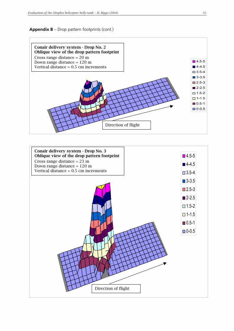
The drop patterns from the Conair belly-tank were of uniform shape, well formed and compact with consistent coverage levels; no gaps were evident (Figure 7).
Because of the consistent coverage by the retardant there is little potential for a fire to break-through and the momentum and concentration of retardant would allow the drop of foam to penetrate dense canopy types where it would provide a reduced but still effective drop pattern.
The extent of coverage by the Conair footprint—averaging 35 m long by 15 m wide—is smaller than that of the Simplex system, but the consistency in its coverage levels and the undivided and uniformly-shaped footprint would make it much more effective.
The concentration of retardant in the centre and to the head of the drop footprint indicates the functioning of the two parallel and adjoining drop-doors.
While the data indicates a uniform concentration of foam within the drop footprint, inspection immediately after each delivery found water, or water with a minimum of foam concentrate, around the edges of the footprint. This is evident on the Linescan images of the Conair delivery system’s drop footprint (Appendix C). However, as this occurs at the periphery of an otherwise consolidated footprint, it does not diminish the effectiveness of the overall drop of foam.
Figure 7 Footprint of retardant dropped from the Conair delivery system (Data is from Conair drop No. 2)
Evaluation of the Simplex helicopter belly-tank � H. Biggs (2004) 11
Conair drop pattern footprint
The drop patterns from the Conair belly-tank were of uniform shape, well formed and compact with consistent coverage levels; no gaps were evident (Figure 7).
4.5-5
4-4.5
3.5-4
3-3.5
2.5-3
2-2.5
1.5-2
1-1.5
0.5-1
0-0.5
Ridge
Plateau
Direction of flight
Figure 7 Footprint of retardant dropped from the Conair delivery system(Data is from Conair drop No. 2)
Because of the consistent coverage by the retardant there is little potential for a fire to break-through and the momentum and concentration of retardant would allow the drop offoam to penetrate dense canopy types where it would provide a reduced but still effectivedrop pattern.
The extent of coverage by the Conair footprint�averaging 35 m long by 15 m wide�issmaller than that of the Simplex system, but the consistency in its coverage levels and theundivided and uniformly-shaped footprint would make it much more effective.
The concentration of retardant in the centre and to the head of the drop footprint indicatesthe functioning of the two parallel and adjoining drop-doors.
While the data indicates a uniform concentration of foam within the drop footprint,inspection immediately after each delivery found water, or water with a minimum of foamconcentrate, around the edges of the footprint. This is evident on the Linescan images ofthe Conair delivery system�s drop footprint (Appendix C). However, as this occurs at the periphery of an otherwise consolidated footprint, it does not diminish the effectiveness ofthe overall drop of foam.

12 Evaluation of the Simplex helicopter belly-tank – H. Biggs (2004) Evaluation of the Simplex helicopter belly-tank – H. Biggs (2004) 13
Drop managementThe design of the tank, the position and size of the drop-doors and how the load is released determine the consistency of the drop pattern and its distribution on the ground. Combinations of different speeds, altitudes, opening sequences of the drop-doors and retardant types may be used to modify the distribution pattern to treat different fuel types.
The evacuation process may be by:
• full salvo, where both (all) drop-doors are opened simultaneously
• string drop, in which the doors are opened sequentially
• split drop, in which the drop-doors are opened to evacuate approximately half of the load, then opened again to evacuate the balance of the load
• restricted drop, where the drop-doors are only partially opened.
Table 4 compares the drop options available from the Simplex and Conair delivery systems. To provide consistent and comparable results (the Simplex delivery system could not provide a restricted drop through the main drop-doors, for instance), only full-salvo drops were used in this trial.
Table 4 Available drop management options (Only option 1 was applied in this trial)
Simplex belly-tank Conair belly-tankDrop options Door activation Drop options Door activation
1 2-door full salvo L then R 1 2-door full salvo R & L simultaneously
2 1-door string drop R only 2 2-door string drop R then L
3 2-door split drop L then R (approx. half volume); L then R (remaining volume)
3 2-door split drop R & L simultaneously (approx. half volume); R & L simultaneously (remaining volume)
4 1-door restricted drop* Middle (third) door 4 1-door restricted drop Either R (RG) or L (RG)
5 2-door restricted drop R (RG) & L (RG) simultaneously
Key to Table 4:
L left drop-doorR right drop-door* No variable gate is available to vary the flow rate for a restricted drop(RG) drop-door action restricted by a variable internal gate
Simplex drop management
Field observations and subsequent review of the photographs and digital video images of a full-salvo evacuation of retardant from the Simplex belly-tank show that the process is staged; with the left drop-door opening before the right one. This action is attributed to the operation of the hydraulic mechanisms for the drop-doors.
The main drop-doors of the Simplex belly-tank are located on either side of the tank and widely separated (Figure 2). The 690-mm distance between the two drop-doors (Table 2) combined with their opening sequence may restrict the flow of retardant from the tank and affect the ability of the system to provide a uniform and concentrated drop.
12 Evaluation of the Simplex helicopter belly-tank – H. Biggs (2004) Evaluation of the Simplex helicopter belly-tank – H. Biggs (2004) 13
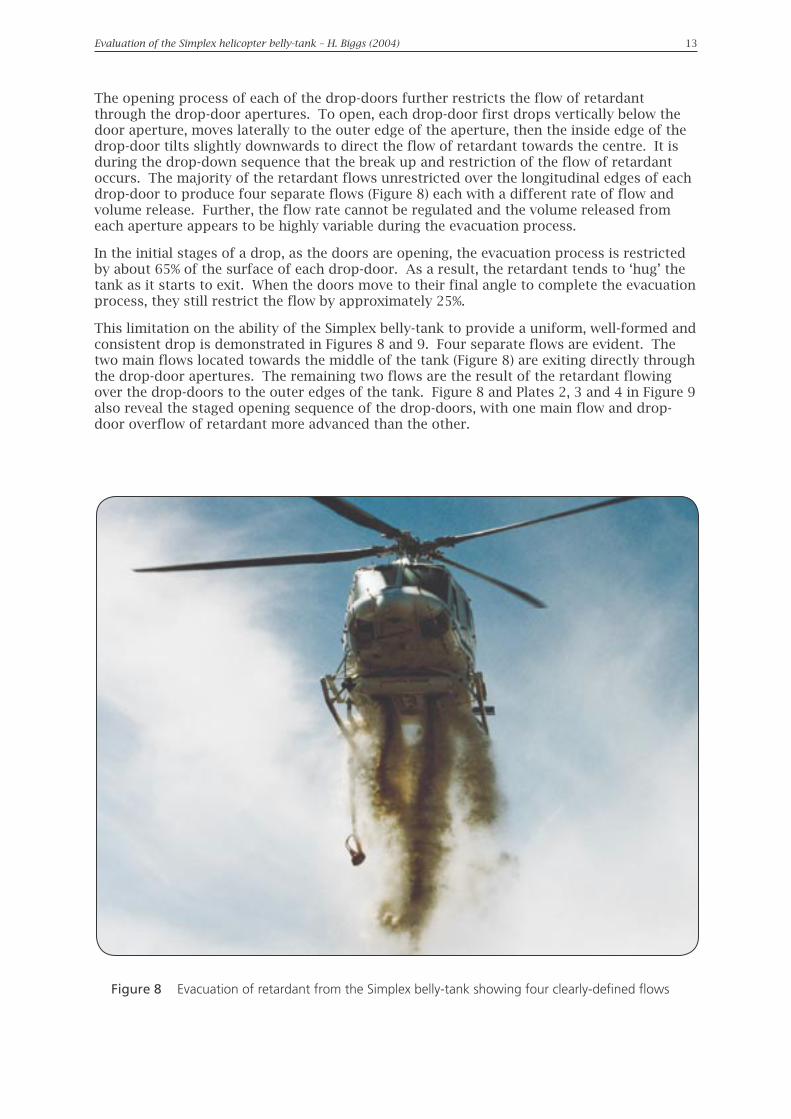
The opening process of each of the drop-doors further restricts the flow of retardant through the drop-door apertures. To open, each drop-door first drops vertically below the door aperture, moves laterally to the outer edge of the aperture, then the inside edge of the drop-door tilts slightly downwards to direct the flow of retardant towards the centre. It is during the drop-down sequence that the break up and restriction of the flow of retardant occurs. The majority of the retardant flows unrestricted over the longitudinal edges of each drop-door to produce four separate flows (Figure 8) each with a different rate of flow and volume release. Further, the flow rate cannot be regulated and the volume released from each aperture appears to be highly variable during the evacuation process.
In the initial stages of a drop, as the doors are opening, the evacuation process is restricted by about 65% of the surface of each drop-door. As a result, the retardant tends to ‘hug’ the tank as it starts to exit. When the doors move to their final angle to complete the evacuation process, they still restrict the flow by approximately 25%.
This limitation on the ability of the Simplex belly-tank to provide a uniform, well-formed and consistent drop is demonstrated in Figures 8 and 9. Four separate flows are evident. The two main flows located towards the middle of the tank (Figure 8) are exiting directly through the drop-door apertures. The remaining two flows are the result of the retardant flowing over the drop-doors to the outer edges of the tank. Figure 8 and Plates 2, 3 and 4 in Figure 9 also reveal the staged opening sequence of the drop-doors, with one main flow and drop-door overflow of retardant more advanced than the other.
Figure 8 Evacuation of retardant from the Simplex belly-tank showing four clearly-defined flows

14 Evaluation of the Simplex helicopter belly-tank – H. Biggs (2004) Evaluation of the Simplex helicopter belly-tank – H. Biggs (2004) 15
Figure 9 Sequential images of drop management from the Simplex belly-tank
14 Evaluation of the Simplex helicopter belly-tank – H. Biggs (2004) Evaluation of the Simplex helicopter belly-tank – H. Biggs (2004) 15
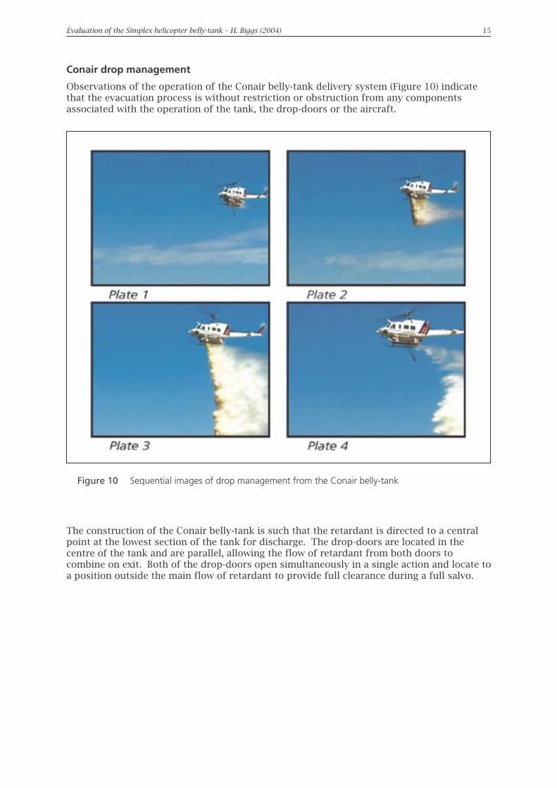
Conair drop management
Observations of the operation of the Conair belly-tank delivery system (Figure 10) indicate that the evacuation process is without restriction or obstruction from any components associated with the operation of the tank, the drop-doors or the aircraft.
The construction of the Conair belly-tank is such that the retardant is directed to a central point at the lowest section of the tank for discharge. The drop-doors are located in the centre of the tank and are parallel, allowing the flow of retardant from both doors to combine on exit. Both of the drop-doors open simultaneously in a single action and locate to a position outside the main flow of retardant to provide full clearance during a full salvo.
Figure 10 Sequential images of drop management from the Conair belly-tank

16 Evaluation of the Simplex helicopter belly-tank – H. Biggs (2004) Evaluation of the Simplex helicopter belly-tank – H. Biggs (2004) 17
Drop controlThe configuration of the drop-doors is important in the formation of the drop pattern footprint. Further, the aerodynamic shape of the mass of retardant formed by the evacuation process will determine the rate of break-up of the load as it is delivered along the flight path.
Figure 11 shows that the Conair belly-tank (left-hand image) confines the flow of retardant to a single solid mass. Optimum effect is achieved because the maximum volume of retardant is distributed evenly along the delivery axis or flight path. The position of the drop-doors, the restricted flow over the doors and variable flow volume from the Simplex belly-tank (right-hand image), on the other hand, prevents the retardant from forming a single mass on exit.
The resultant drop footprints from the Conair and Simplex delivery systems are indicated in Figures 12 and 13 respectively.
Figure 11 Comparison of the evacuation processes of the Conair (left) and Simplex delivery systems, showing the level of control during delivery

16 Evaluation of the Simplex helicopter belly-tank – H. Biggs (2004) Evaluation of the Simplex helicopter belly-tank – H. Biggs (2004) 17
Figure 12 Drop control by the Conair delivery systemb (Conair Drop No. 3)
Evaluation of the Simplex helicopter belly-tank � H. Biggs (2004) 17
Drop control from the Conair deliverysystem
The resultant footprint of the retardantdrop from the Conair delivery system
5.5-6
5-5.5
4.5-5
4-4.5
3.5-4
3-3.5
2.5-3
2-2.5
1.5-2
1-1.5
0.5-1
Direction of delivery
Figure 12 Drop control by the Conair delivery system (Conair Drop No. 3)
18 Evaluation of the Simplex helicopter belly-tank – H. Biggs (2004) Evaluation of the Simplex helicopter belly-tank – H. Biggs (2004) 19
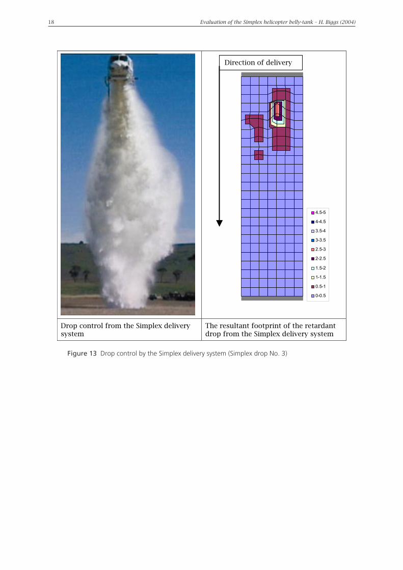
Figure 13 Drop control by the Simplex delivery system (Simplex drop No. 3)
18 Evaluation of the Simplex helicopter belly-tank � H. Biggs (2004)
Drop control from the Simplex deliverysystem
The resultant footprint of the retardantdrop from the Simplex delivery system
4.5-5
4-4.5
3.5-4
3-3.5
2.5-3
2-2.5
1.5-2
1-1.5
0.5-1
0-0.5
Direction of delivery
Figure 13 Drop control by the Simplex delivery system (Simplex drop No. 3)

18 Evaluation of the Simplex helicopter belly-tank – H. Biggs (2004) Evaluation of the Simplex helicopter belly-tank – H. Biggs (2004) 19
Drop flow rate effectsSimplex drop flow rate effects
The release of retardant from the Simplex belly-tank starts slowly. This may be attributed to a number of factors including, amongst other things, the available head of pressure, positions and sequence of operation of the drop-doors, the variable volume flow and a possible low-pressure area beneath the tank. The rate of release then reaches a peak where all flows from the drop-door apertures and deflected flows of retardant combine. It then slowly declines with the evacuation being incomplete (some retardant remained in the tank). The rates of evacuation for each drop in the test series for the Simplex delivery system are set out in Table 5. The evacuation time of a full salvo from the Simplex system is about twice that of the Conair system (Table 6).
Table 5 Evacuation times for the Simplex delivery system
Simplex drop No.
Digital camera
view
Action Evacuation timing1
Minutes Seconds Decimalseconds
Net time (seconds)
1 Down-range
Start 00 58 0804.80
Finish 01 02 88Cross-range
Start 01 17 2004.60
Finish 01 21 80
RemoteStart 00 28 68
04.64Finish 00 33 32
2 Down-range
Start 01 55 8804.20
Finish 02 00 08Cross-range
Start 02 13 2404.84
Finish 02 18 08
RemoteStart 00 54 84
04.76Finish 00 59 60
3 Down-range
Start 02 55 5604.40
Finish 02 59 96Cross-range
Start 03 15 5604.96
Finish 03 20 52
RemoteStart 01 33 80
04.28Finish 01 38 08
Note 1: Synchronised times as recorded by the digital cameras
Photographs and measurements of the drops show that the retardant does not form a concentrated mass on exit and has limited uniformity on the ground. There is no forward movement of the drop itself, rather it is ‘painted’ or ‘laid’ on the ground by the forward movement of the aircraft.
The paired images in Figures 14 and 15 and Figures 16 and 17 compare the effects of the flow control achieved by the Simplex and Conair delivery systems. For the Simplex system, Figures 14 and 16 show, progressively, the initial stages of the drop prior to ground contact, part of the initial flow and the peak flow contacting the ground, and the remaining part of the load reducing in volume and exiting slowly. The extended time for the drop to occur allows for partial break-up, drift and variable dispersal of the drop prior to contact with the ground.

20 Evaluation of the Simplex helicopter belly-tank – H. Biggs (2004) Evaluation of the Simplex helicopter belly-tank – H. Biggs (2004) 21
Note: The images in each pair of plates (both Plate 1s for instance) are from equivalent times.
Figure 14 Side view of the drop flow from the Simplex delivery system
Figure 15 Side view of the drop flow from the Conair delivery system

20 Evaluation of the Simplex helicopter belly-tank – H. Biggs (2004) Evaluation of the Simplex helicopter belly-tank – H. Biggs (2004) 21
Conair drop flow rate effects
Figures 15 and 17 show that the rate of release from the Conair delivery system increases rapidly to its maximum. This is attributed to a number of factors, including the centrally-located parallel position of the drop-doors, the ability of the doors to move clear of the evacuation process and the depth and width of the tank which both provides a greater head of pressure and allows for an unrestricted and rapid flow of the retardant. The rates of evacuation for each drop in the test series are set out in Table 6.
Table 6 Evacuation times for the Conair delivery system
Conair drop No.
Digital camera
view
Action Evacuation timing1
Minutes Seconds Decimal seconds
Net time (seconds)
1 Down-range
Start 03 50 2802.06
Finish 03 52 34Cross-range
Start 04 01 0001.98
Finish 04 02 98
RemoteStart 01 57 88
01.92Finish 01 59 80
2 Down-range
Start 04 24 3602.04
Finish 04 26 40Cross-range
Start 04 36 5202.04
Finish 04 38 60
RemoteStart 02 28 34
02.10Finish 02 30 44
3 Down-range
Start 05 04 1602.06
Finish 05 06 22Cross-range
Start 05 15 7602.04
Finish 05 17 80
RemoteStart 02 56 12
02.12Finish 02 58 24
Note 1: Synchronised times as recorded by the digital cameras
The drop footprint pattern from the Conair delivery system is more uniform and consistent in shape than that of the Simplex system and tends to form a single line of concentrated retardant, providing a high coverage level. The effective area of concentrated retardant from the Conair system also tends to be longer than that produced by the Simplex system.
There is no restriction to the flow of retardant as it exits the Conair tank. The resultant drop remains compact and the degree of dispersal or break-up during the delivery process is limited. Figures 15 and 17 clearly show the single, compact column of retardant. The drop also displays characteristics of forward movement. The clear evacuation from the delivery system can also be seen in the images.

22 Evaluation of the Simplex helicopter belly-tank – H. Biggs (2004) Evaluation of the Simplex helicopter belly-tank – H. Biggs (2004) 23
Note: The images in each pair of plates (both Plate 1s for instance) are from equivalent times.
Figure 16 Front view of the control of a drop from the Simplex delivery system
Figure 17 Front view of the control of a drop from the Conair delivery system

22 Evaluation of the Simplex helicopter belly-tank – H. Biggs (2004) Evaluation of the Simplex helicopter belly-tank – H. Biggs (2004) 23
Characteristics of delivered retardantTo ensure valid comparisons of the drops delivered by the two delivery systems, foam concentrate was to be injected into each load of water at a rate of 0.5% by volume.
Mixing of the foam (or other fire retardant) through the load of water occurs partially as a result of agitation in the tank while the helicopter is travelling and partially during the evacuation process. However, the retardant may not always be distributed evenly through the load. Further, on delivery, the edges of the drop of retardant mix inevitably disperse and thin out through movement of the mass of water/foam and friction with the air. As a result, the edges of a drop may comprise just water or only a small amount of foam. This is usually not a problem when it occurs at the periphery of an otherwise consolidated drop.
Retardant delivered by the Simplex delivery system
The nature of the foam distributed from the Simplex delivery system was not consistent with the characteristics expected of a mixture of 0.5% of foam concentrate in water. The retardant was warm to the touch and had small and slightly discoloured bubbles, indicating a reduced proportion of water. Further, it adhered to objects and neither penetrated nor flowed. These observations suggested that the proportion of foam concentrate in the mixture was greater than 0.5% and could have been greater than 0.7%. The extended duration of the drop of retardant from the Simplex belly-tank, combined with the suspected higher concentration of foam, contributed to the break up, drift and variable dispersal of the drop on the ground.
It was suspected that the probable higher proportion of foam concentrate in the retardant mixture was a result of residual concentrate in the injection mechanism. To test this suspicion, additional drops of retardant from the Simplex belly-tank (additional to the three scheduled for the evaluation work) were made using foam concentrate in proportions less than the recommended 0.5% of mixture. These additional drops displayed characteristics consistent with the desired 0.5% levels of foam concentrate.
It was noted previously that the Simplex delivery system produced two distinct ridges in the drop footprint and water, or water with a small amount of foam, was found in the gap between the two ridges. This is attributed to the foam injection system and the distance between the two drop-doors. As explained above, the periphery of any drop of foam is dispersed. Although not of concern with consolidated drops, thinning out of the foam on the periphery of the two ridges formed by the drop from the Simplex system means that there is an inconsistent coverage level of foam and an area through which a fire may break through.
Retardant delivered by the Conair delivery system
The retardant mixture delivered by the Conair belly-tank displayed characteristics consistent with 0.5% of foam concentrate. As noted above, while the data indicates a uniform concentration of foam within the drop footprint, water, or water with a minimum of foam concentrate, was found around the edges of the footprint. However, as it lies at the periphery of an otherwise consolidated footprint, it does not diminish the effectiveness of the overall drop of foam.

24 Evaluation of the Simplex helicopter belly-tank – H. Biggs (2004) Evaluation of the Simplex helicopter belly-tank – H. Biggs (2004) 25
DiscussionComparison of the performances of the Simplex and Conair belly-tanks indicated marked differences between the two. The retardant mixture delivered by the Simplex belly-tank was variable, dispersed and inconsistent in shape, with scattered concentrations of retardant. The drops from the Conair belly-tank were more uniform, well-formed and consistent in shape and coverage.
Simplex belly-tank
Belly-tank design
The retention of retardant within the Simplex belly-tank may be the result of the shallow depth of the tank and the lack of a distinct slope from the head of the tank to the drop-door apertures. In the absence of strong directional flow in the tank, the opportunity for a rapid flow of retardant may be greatly diminished.
The drop-doors are widely separated (Figure 2 and Table 1), placed as they are on either side of the tank. This also affects the efficient flow of retardant.
The structural design of the Simplex belly-tank may further complicate its ability to produce a consistent mass of retardant on evacuation. While the tank’s aerodynamic characteristics appear suitable for aircraft movement, its slim and efficient design may produce a low-pressure area beneath it. This could also prevent the clean evacuation of retardant.
Drop-door construction
The combined area of the drop-door apertures of the Simplex belly-tank (0.73 m2 - Table 1) appears to be too small compared to the bottom surface area of the tank. The shallow design of the tank, the wide separation of the doors and the narrow drop-door apertures combine to produce two main flows and two secondary flows over the drop-doors during the evacuation process (Figures 8 and 18). The volume of each flow is also variable.
Drop-door opening sequence
The evacuation of retardant from the Simplex belly-tank is staged, with the left (co-pilot’s side) drop-door opening before that on the right (Table 4). The delay before the second door opens is measurable. This contributes significantly to the variability in flow from both drop-doors and consequently affects the distribution and levels of concentration of retardant within the drop footprint. (Paradoxically, during a test without retardant in the tank, the drop-door opening sequence reversed, with the right door opening before the left.)
Drop-door action
The Simplex drop-doors do not open in a single action; they are released down from the drop-door apertures in one action and then positioned partially to the outside of the apertures in a separate action. During the first action the retardant mixture flows over all edges of the drop-doors, including the leading edges. The second action of the drop-doors, which does not completely clear the apertures, restricts the evacuation process and maintains the split flows of retardant until the later stages of the drop (Figure 18).

24 Evaluation of the Simplex helicopter belly-tank – H. Biggs (2004) Evaluation of the Simplex helicopter belly-tank – H. Biggs (2004) 25
Conair belly-tank
During the evacuation process, the two drop-doors of the Conair belly-tank open simultaneously and move clear of the apertures to provide an uninterrupted flow. The belly-tank construction is narrow and deep, which would potentially produce a greater head of pressure in the load. The load is also directed to a central point for the evacuation process.
Figure 18 Assumed evacuation process from the Simplex Model 304 Fire Attack belly-tank
Figure 19 Assumed evacuation process from the Conair belly-tank
Evaluation of the Simplex helicopter belly-tank � H. Biggs (2004) 25
Figure 18 Assumed evacuation process from the Simplex Model 304 Fire Attack belly-tank
Conair belly-tank
During the evacuation process, the two drop-doors of the Conair belly-tank opensimultaneously and move clear of the apertures to provide an uninterrupted flow. The belly-tank construction is narrow and deep, which would potentially produce a greater head ofpressure in the load. The load is also directed to a central point for the evacuation process.
Drop-door
Overflow Main flows
Drop-door
Assumed internal movement of retardant during evacuation process
Overflow
NOT TO SCALE
Assumed internal movement of retardant during evacuation process
Baffle
NOT TO SCALE
Drop-door
Main flow
Drop-door
Figure 19 Assumed evacuation process from the Conair belly-tank

26 Evaluation of the Simplex helicopter belly-tank – H. Biggs (2004) Evaluation of the Simplex helicopter belly-tank – H. Biggs (2004) 27
ConclusionsThe drop footprints indicate that the current Simplex retardant delivery system would perform adequately for operational purposes in grassland and low open-canopy eucalypt forest. However, fire-retardant foam delivered by the current system would have difficulty in effectively penetrating dense canopies in heathlands or mature eucalypt forests. The Simplex belly-tank will require further assessment in a range of vegetation types.
This trial has identified a number of features of the Simplex Model 304 Fire Attack belly-tank (listed below) that restrict its ability to achieve a high standard of performance. Possible solutions are suggested (in italics):
A. The shallow design of the tank means that the pressure head in the tank is low and therefore the speed of evacuation is reduced. It may also contribute to the uncontrolled movement and retention of retardant within the tank. Baffles in the tank may help balance the flow of retardant inside and from the tank during a full salvo.
B. The wide separation of the drop-doors across the tank inhibits the formation of a combined single mass of retardant. This is a major factor restricting the ability of the tank to provide an effective drop pattern. It may not be structurally feasible to modify the positions of the drop-doors on the current model of the delivery system.
C. The total surface area of the drop-doors seems to be too small compared to the bottom surface area of the tank. The fitting of wider drop-doors and using the third drop-door may allow a more efficient evacuation.
D. The wide separation of the drop-doors and the consequent development of variable volume flows contribute to the irregularities in the drop footprint. The provision of a partitioned tank would balance the flow of retardant from each drop-door during a full salvo and allow for more control of split drops.
E. The concentration of foam concentrate in the retardant mixture delivered by the system seemed to be higher than the required rate of 0.5%. The foam injection system appeared to contain residues of foam concentrate from a previous operation. The ability to re-calibrate or assess the efficiency of the injection system should be addressed2.
F. The drop-door opening sequence is staged with the left door opening before the right one. Enabling both drop-doors to open simultaneously and bringing the third smaller door into operation may provide a more uniform drop footprint with a more consistent level of coverage.
G. Four separate flows of retardant form over the surfaces of the drop-doors. The opening process of the drop-doors and their partial obstruction of the apertures contribute to this problem. Restriction of the flows that occur over the outer edges of the drop-doors would enhance the drop characteristics of the evacuation process. A flexible shroud connecting the outside and leading edges of the drop-doors to the respective edges of the apertures may restrict the uncontrolled overflows and direct them back into the central flow. In addition, modification to the angle of tilt of the drop-doors at full salvo may allow the retardant to evacuate more efficiently.
2 The manufacturer resolved this problem a week after the tests by reducing the length of the injection hose within the belly-tank. All new tanks subsequently produced by Simplex are to incorporate this modification (Personal communication, D. Sullivan, Base Manager Lloyd Helicopters, Latrobe Valley, April 2000).

26 Evaluation of the Simplex helicopter belly-tank – H. Biggs (2004) Evaluation of the Simplex helicopter belly-tank – H. Biggs (2004) 27
Recommendations
Recommendation 1
Further investigation should be undertaken to determine if the suggested modifications to the Simplex Model 304 Fire Attack belly-tank could be achieved. Simplex, Lloyd Helicopters (now CHC Helicopters Australia), the Department and the State Aircraft Unit should consult to determine if the restrictions inherent in the delivery system could be ameliorated.
Recommendation 2
In accordance with the classification system used by the Department of Natural Resources and Environment in 2000, the Simplex Model 304 Fire Attack belly-tank be QUALIFIED FOR APPROVAL3 for use for fighting wildfires in Victoria. The Department should encourage the continued operational use of the Simplex belly-tank subject to review of the “qualified” aspects of the delivery system and their improvements, specifically in the areas of uniformity of drop pattern and concentration as well as the speed of evacuation of the tank.
3 In 2002, the Department reviewed the approval process for aircraft retardant delivery systems and developed an approval rating (see Appendix F) for future applications. Under the revised classifications, ‘qualified for approval’ translates to:
Provisional Approval (iii) “Provisional Approval is given to use the delivery system subject to conditions as recommended by the State Aircraft Unit.”

28 Evaluation of the Simplex helicopter belly-tank – H. Biggs (2004) Evaluation of the Simplex helicopter belly-tank – H. Biggs (2004) 29
Addendum
A draft copy of this report was forwarded to Simplex USA for their information and comment. In response, Mr David Hastings, Director of Engineering from Simplex visited Australia in November 2000 and engaged in discussions with representatives of Lloyd Helicopters and the Department.
Mr Hastings commended the report and thanked the parties involved in the trial. He advised that the deficiencies of the delivery system identified in the report were being investigated and modifications and improvements were being developed to improve its performance.
Mr Hastings advised that, in consultation with Lloyd Helicopters, modifications to the foam injection system and drop-door activation sequence had been made. In addition, the inclusion of the third drop-door in the evacuation process had assisted in the improvement of the drop control.
Mr Hastings subsequently advised that Simplex was developing and testing a flexible curtain that would reduce the amount of retardant that flows over the drop-doors and direct the flow of retardant towards the centre of the belly-tank during the evacuation process.
No documented evidence of these developments was provided.

28 Evaluation of the Simplex helicopter belly-tank – H. Biggs (2004) Evaluation of the Simplex helicopter belly-tank – H. Biggs (2004) 29
Acknowledgments
The Department, the author and Canadian Helicopter Company, Australia (formally Lloyd Helicopters) thank the following for their assistance with the belly-tank trial:
• Conair Helicopters, Abbotsford, British Colombia, Canada
• Officers and staff of the State Aircraft Unit (previously Aviation Services, Fire Management, Department of Natural Resources and Environment), Victoria, Australia
• Project Fire Fighters, Bacchus Marsh Fire District, of the former Department of Natural Resources and Environment, Victoria, Australia
• Simplex Manufacturing, Portland, Oregon, United States of America
• Management and staff of Greystones Pastoral Company, Bacchus Marsh, Victoria, Australia

Evaluation of the Simplex helicopter belly-tank – H. Biggs (2004) 31
Appendices

Evaluation of the Simplex helicopter belly-tank – H. Biggs (2004) 31
Appendix A Assessment process
Setting out the test area
The test area was established on private land (Greystones Homestead) five kilometres south-west of Bacchus Marsh, Victoria.
The site selected was on a level section of a cultivated paddock large enough for the establishment of a 120-metre by 120-metre test area. It was close to adequate water supplies suitable for hover filling and to areas suitable for the landing of helicopters.
The vegetation on the test area was cut with a rotary mower to minimise obstructions to the measurement of the depth of foam.
Project Fire Fighters from the Bacchus Marsh Fire District were engaged to prepare the drop zones and collect the required data after each drop of foam was delivered.
Figure A1
Marking out a down-range axis
Figure A2
A base axis with 5-metre intervals markedShows also the mowing of the vegetation.
Figure A3
Completed test areaWhite dots mark the 5-metre X 5-metre grid points.

32 Evaluation of the Simplex helicopter belly-tank – H. Biggs (2004) Evaluation of the Simplex helicopter belly-tank – H. Biggs (2004) 33
Data collection and recording
Seven assessment crews were formed, each consisting of three people: two to undertake the measurements and one to record the data. After each drop of foam, each crew proceeded from the cross-range base line along the down-range axis of their respective five-metre grid line, measuring and recording the depth of foam at each grid point and the extent and depth of its dispersal in four directions—up- and down-range and in both directions cross-range—from the grid point.
All data collected by the assessment crews was transferred into an Excel™ spreadsheet. Quality checks conducted during the collection process identified minor errors in the accuracy of the data collected from the secondary sample points (those at the limits of dispersal of some of the foam).
The inaccuracies related to the recording of the depth of coverage of retardant at these secondary sample points. This was confirmed when the data was interpreted through the spreadsheet. The errors were attributed to the absence of simulated assessment runs and the limited time given to briefing and training of the assessment crews.
The errors did not compromise the integrity of the assessment process, however, as the control sample points were at the specified 5-metre by 5-metre grid points and measurements at these points were consistent.
Figure A5 Assessing a drop of foam from the Conair delivery system
Figure A6 Assessing a drop of foam from the Simplex delivery system

32 Evaluation of the Simplex helicopter belly-tank – H. Biggs (2004) Evaluation of the Simplex helicopter belly-tank – H. Biggs (2004) 33Evaluation of the Simplex helicopter belly-tank - H. Biggs (2004) 33
Appendix B Drop pattern footprints
2.5-3
2-2.5
1.5-2
1-1.5
0.5-1
0-0.5
Direction of flight
Simplex delivery system - Drop No. 1 Oblique view of the drop pattern footprint
Cross range distance = 21 m Down range distance = 120 m Vertical distance = 0.5 cm increments
4.5-5
4-4.5
3.5-4
3-3.5
2.5-3
2-2.5
1.5-2
1-1.5
0.5-1
0-0.5
Direction of flight
Simplex delivery system - Drop No. 2 Oblique view of the drop pattern footprintCross range distance = 30 mDown range distance = 120 m Vertical distance = 0.5 cm increments

34 Evaluation of the Simplex helicopter belly-tank – H. Biggs (2004) Evaluation of the Simplex helicopter belly-tank – H. Biggs (2004) 3534 Evaluation of the Simplex helicopter belly-tank � H. Biggs (2004)
Appendix B � Drop pattern footprints (cont.)
4.5-5
4-4.5
3.5-4
3-3.5
2.5-3
2-2.5
1.5-2
1-1.5
0.5-1
0-0.5
Direction of flight
Simplex delivery system - Drop No. 3 Oblique view of the drop pattern footprintCross range distance = 27 m Down range distance = 120 m Vertical distance = 0.5 cm increments
4.5-5
4-4.5
3.5-4
3-3.5
2.5-3
2-2.5
1.5-2
1-1.5
0.5-1
0-0.5
Direction of flight
Conair delivery system - Drop No. 1 Oblique view of the drop pattern footprintCross range distance = 20 m Down range distance = 120 m Vertical distance 0.5 cm increments
34 Evaluation of the Simplex helicopter belly-tank – H. Biggs (2004) Evaluation of the Simplex helicopter belly-tank – H. Biggs (2004) 35Evaluation of the Simplex helicopter belly-tank � H. Biggs (2004) 35
Appendix B � Drop pattern footprints (cont.)
4.5-5
4-4.53.5-43-3.5
2.5-32-2.5
1.5-21-1.50.5-1
0-0.5
Direction of flight
Conair delivery system - Drop No. 2 Oblique view of the drop pattern footprintCross range distance = 20 m Down range distance = 120 m Vertical distance = 0.5 cm increments
4.5-5
4-4.5
3.5-4
3-3.5
2.5-3
2-2.51.5-2
1-1.5
0.5-1
0-0.5
Direction of flight
Conair delivery system - Drop No. 3 Oblique view of the drop pattern footprintCross range distance = 23 m Down range distance = 120 m Vertical distance = 0.5 cm increments

36 Evaluation of the Simplex helicopter belly-tank – H. Biggs (2004) Evaluation of the Simplex helicopter belly-tank – H. Biggs (2004) 37
Appendix C Infrared Linescan images
Infrared Linescan image of Simplex belly-tank drop No. 1
Direction of flight
Simplex drop No. 1

36 Evaluation of the Simplex helicopter belly-tank – H. Biggs (2004) Evaluation of the Simplex helicopter belly-tank – H. Biggs (2004) 37
Appendix C – Infrared Linescan images (cont.)
Infrared Linescan image of Simplex belly-tank drop No. 2
Direction of flight
Simplex drop No. 2

38 Evaluation of the Simplex helicopter belly-tank – H. Biggs (2004) Evaluation of the Simplex helicopter belly-tank – H. Biggs (2004) 39
Appendix C – Infrared Linescan images (cont.)
Infrared Linescan image of Simplex belly-tank drop No. 3
Direction of flight
Simplex drop No. 3

38 Evaluation of the Simplex helicopter belly-tank – H. Biggs (2004) Evaluation of the Simplex helicopter belly-tank – H. Biggs (2004) 39
Appendix C – Infrared Linescan images (cont.)
Infrared Linescan image of Conair belly-tank drop No. 1
Direction of flight
Conair drop No. 1
40 Evaluation of the Simplex helicopter belly-tank – H. Biggs (2004) Evaluation of the Simplex helicopter belly-tank – H. Biggs (2004) 41
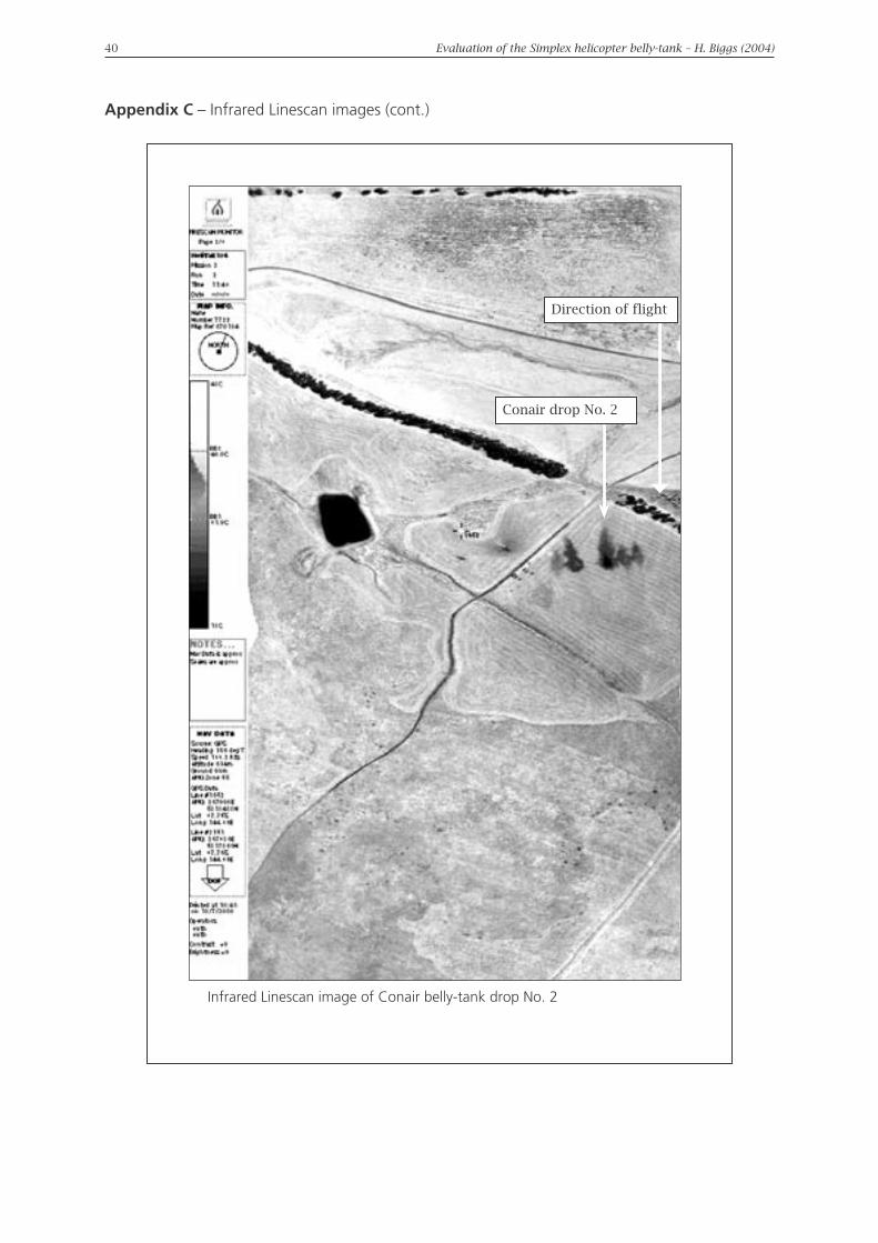
Appendix C – Infrared Linescan images (cont.)
Infrared Linescan image of Conair belly-tank drop No. 2
Direction of flight
Conair drop No. 2

40 Evaluation of the Simplex helicopter belly-tank – H. Biggs (2004) Evaluation of the Simplex helicopter belly-tank – H. Biggs (2004) 41
Appendix C – Infrared Linescan images (cont.)
Infrared Linescan image of Conair belly-tank drop No. 3
Direction of flight
Conair drop No. 3

42 Evaluation of the Simplex helicopter belly-tank – H. Biggs (2004) Evaluation of the Simplex helicopter belly-tank – H. Biggs (2004) 43
Appendix D
Comparing the progress of load delivery by the Conair and Simplex systems
The image pairs in each plate of the following sequence (Plates 1 to 35) compare the performances of the Conair (left) and Simplex (right) delivery systems. The two images in each plate were taken at equivalent times by a digital camera.
Immediately prior to start of evacuation Drop-doors and retardant flow commences
Retardant flow evident from both tanks Centralised flow commences in the Conair drop
Dispersed flow becomes evident in Simplex drop
A single central column starts to form
Multiple flows start to form Four individual columns have formed in the retardant flow from the Simplex belly-tank

42 Evaluation of the Simplex helicopter belly-tank – H. Biggs (2004) Evaluation of the Simplex helicopter belly-tank – H. Biggs (2004) 43
Appendix D – Comparing the progress of load delivery by the Conair (left) and Simplex (right) systems (cont.)
The four individual columns from the Simplex belly-tank com-prise different rates and volumes
Conair belly-tank flow con-tinues with a single column
of retardant
The two inner columns of different sizes in the Simplex drop result from the drop-doors opening at different times; the two
outer flows indicate the retardant flow over the drop doors
The single column of retardant persists from the
Conair belly-tank
A distinct gap becomes apparent between the main flows of retardant from the
Simplex belly-tank
Break up of the retardant flow from the Simplex belly-tank occurs as a result of the retardant ‘hanging’ and ‘trailing’
The single column of retardant flowing from the Conair belly-tank persists with minimal ‘hanging’
One flow begins to dominate in the flow from the Simplex
belly-tank as a result of a delay in the drop-door
opening sequence

44 Evaluation of the Simplex helicopter belly-tank – H. Biggs (2004) Evaluation of the Simplex helicopter belly-tank – H. Biggs (2004) 45
Appendix D – Comparing the progress of load delivery by the Conair (left) and Simplex (right) systems (cont.)
The flow of retaradant over the drop doors of the Simplex belly-tank has reduced significantly but a single column of retardant
has not formed
The break up of the flow from the Simplex belly-tank is demonstrated by the width of the two main columns
The break up from the Simplex belly-tank is further demonstrated by the light shaded patches developing within
the columns
The Conair belly-tank has maintained a single column of retardant with a continuous flow
Evacuation of the Conair belly-tank is complete
The columns of retardant from the Simplex belly-tank display more evidence of
break up
The Simplex belly-tank evacuation process continues, breaking up with ‘hanging’ and ‘trailing’

44 Evaluation of the Simplex helicopter belly-tank – H. Biggs (2004) Evaluation of the Simplex helicopter belly-tank – H. Biggs (2004) 45
Appendix D – Comparing the progress of load delivery by the Conair (left) and Simplex (right) systems (cont.)
The initial stages of the columns from both belly-tanks contact the ground. The Conair belly-tank’s column has retained
significant forward momentum. The Simplex belly-tank columns have no forward momentum and are trailing behind the aircraft
(indicated by the amount of shadow under the flow)
The column from the Conair belly-tank has impacted the ground and is beginning to rebound
The Conair belly-tank’s flow column is rebounding upwards and forward with considerable momentum
The flow column from the Conair belly-tank maintains considerable forward momentum and a consistent form
The flow columns from the Simplex belly-tank continue to disperse and trail, with the retardant being laid onto the ground

46 Evaluation of the Simplex helicopter belly-tank – H. Biggs (2004) Evaluation of the Simplex helicopter belly-tank – H. Biggs (2004) 47
Appendix D – Comparing the progress of load delivery by the Conair (left) and Simplex (right) systems (cont.)
Forward movement of the retardant evacuated from the Conair belly-tank continues after impacting the ground
Note the cavity that has developed withing the base of the retardant flow from the Simplex delivery system. This cavity
appears as a gap within the drop footprint
Retardant traveling at low velocity at the periphery of the column formed by the high velocity flow from the Conair
delivery system is gradually dispersing
The flows of retardant from the Simplex delivery system continues to break up
The majority of the low velocity retardant flow from the Conair delivery system is falling back into the drop footprint
The shadow under the flow of retardant from the Conair system indicates that the size of the drop footprint remains constrained

46 Evaluation of the Simplex helicopter belly-tank – H. Biggs (2004) Evaluation of the Simplex helicopter belly-tank – H. Biggs (2004) 47
Appendix D – Comparing the progress of load delivery by the Conair (left) and Simplex (right) systems (cont.)
The shadow of the flow of the retardant from the Simplex system indicates that it is running ahead of the required drop area and
leading the main body of retardant
Portions of the retardant flow from the Simplex delivery system are breaking up and drifting to the right of frame
The flow of retardant from the Conair delivery system shows minimal drift outside the main body of the footprint
Break up and drift continues to occur in the flow of retardant from the Simplex delivery system and the evacuation from the
belly-tank remians incomplete
The Simplex delivery system has excited camera frame although the evacuation process is continuing

48 Evaluation of the Simplex helicopter belly-tank – H. Biggs (2004) Evaluation of the Simplex helicopter belly-tank – H. Biggs (2004) 49
Appendix E Automatic weather station data
AVALON AUTOMATIC WEATHER STATION DATE 09/03/2000
Time
EDST1
Temp.
(˚C)
R.H.
(%)
Wind Pressure
(hPa)
Rain from 0900 hrs
(mm)
DI2 FDI3
Direction Average
(km/h)
Gust
(km/h)
0800 12.6 92 ENE 6 9 1022.2 000.0 67 10830 13.5 89 0 0 0 1022.1 000.0 67 10900 15.4 87 NE 2 6 1022.2 000.0 67 10930 19.0 67 E 15 20 1022.2 000.0 68 31000 19.7 63 E 15 19 1022.1 000.0 68 41030 20.2 62 ESE 15 20 1022.0 000.0 68 41100 20.3 62 ESE 20 24 1022.0 000.0 68 41130 20.6 59 ESE 20 28 1021.8 000.0 68 51200 21.3 56 ESE 19 28 1021.3 000.0 68 51230
1300 22.2 47 ESE 20 26 1020.2 000.0 68 81330 22.4 47 ESE 17 22 1019.5 000.0 68 71400 22.8 45 ESE 20 26 1019.2 000.0 68 91430 23.6 40 ESE 22 28 1018.8 000.0 68 111500 24.1 43 ESE 19 26 1018.4 000.0 68 91530 24.9 40 S 15 20 1017.8 000.0 68 101600 24.0 42 ESE 19 24 1017.4 000.0 68 101630 24.2 45 ESE 17 22 1016.9 000.0 68 81700 24.3 45 ESE 17 22 1016.6 000.0 68 8
LAVERTON AUTOMATIC WEATHER STATION DATE 09/03/2000Time
EDST1
Temp.
(˚C)
R.H.
(%)
Wind Pressure
(hPa)
Rain from 0900 hrs
(mm)
DI2 FDI3
Direction Average
(km/h)
Gust
(km/h)
0800 11.6 86 NW 11 13 1022.7 000.0 1 720830 13.7 82 NW 9 11 1022.8 000.0 1 720900 15.9 73 WNW 6 7 1022.8 000.0 2 720930 17.5 66 0 0 0 1022.7 000.0 2 731000 19.1 59 SW 4 9 1022.2 000.0 3 731030 20.5 51 SSW 4 9 1022.4 000.0 4 731100 21.2 48 N 6 11 1022.2 000.0 5 731130 21.6 52 SE 13 19 1022.2 000.0 5 731200 21.4 49 S 9 13 1021.7 000.0 5 731230 22.3 45 SSE 7 11 1020.9 000.0 6 731300 23.4 43 ESE 9 17 1020.2 000.0 7 731330 23.2 40 SSE 15 20 1019.8 000.0 9 731400 23.1 38 SSE 13 20 1019.6 000.0 9 731430 23.5 39 SSE 13 20 1019.2 000.0 9 731500 24.5 36 S 11 17 1018.8 000.0 10 731530 24.5 35 SE 9 19 1018.1 000.0 10 731600 24.5 40 SE 13 22 1017.7 000.0 9 731630 24.7 38 S 9 17 1017.2 000.0 9 731700 25.2 36 S 9 15 1016.9 000.0 10 73
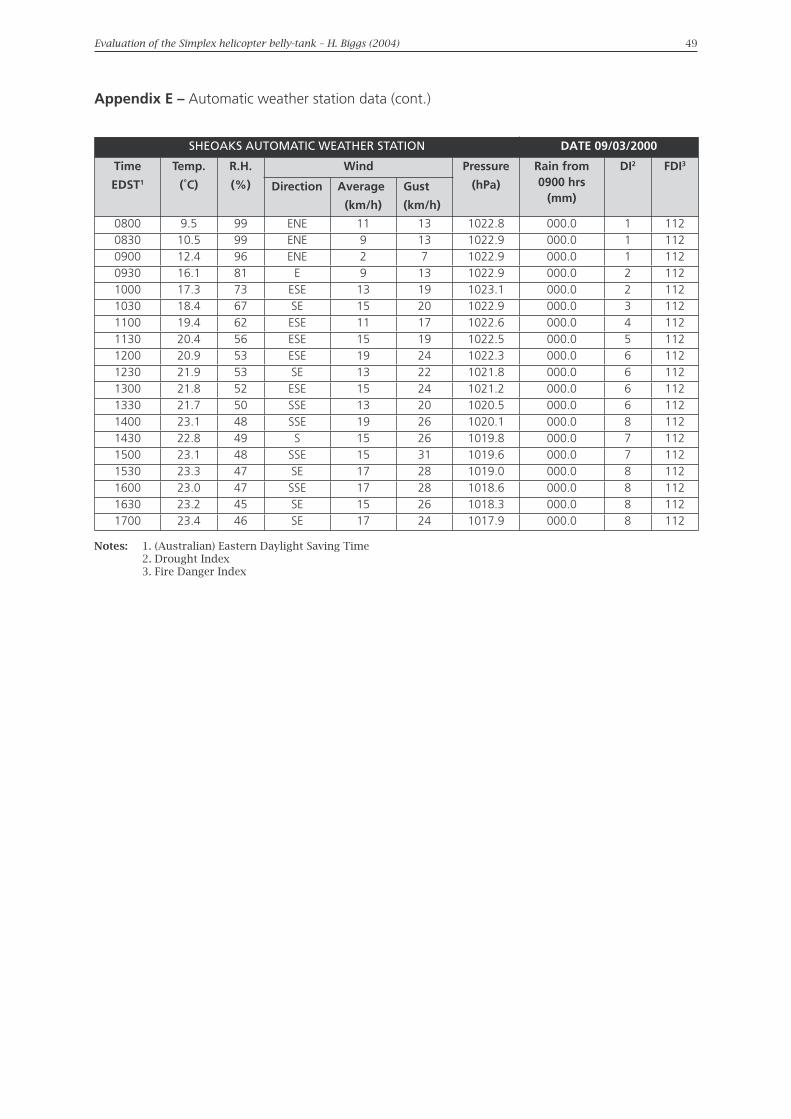
48 Evaluation of the Simplex helicopter belly-tank – H. Biggs (2004) Evaluation of the Simplex helicopter belly-tank – H. Biggs (2004) 49
Appendix E – Automatic weather station data (cont.)
SHEOAKS AUTOMATIC WEATHER STATION DATE 09/03/2000
Time
EDST1
Temp.
(˚C)
R.H.
(%)
Wind Pressure
(hPa)
Rain from 0900 hrs
(mm)
DI2 FDI3
Direction Average
(km/h)
Gust
(km/h)
0800 9.5 99 ENE 11 13 1022.8 000.0 1 1120830 10.5 99 ENE 9 13 1022.9 000.0 1 1120900 12.4 96 ENE 2 7 1022.9 000.0 1 1120930 16.1 81 E 9 13 1022.9 000.0 2 1121000 17.3 73 ESE 13 19 1023.1 000.0 2 1121030 18.4 67 SE 15 20 1022.9 000.0 3 1121100 19.4 62 ESE 11 17 1022.6 000.0 4 1121130 20.4 56 ESE 15 19 1022.5 000.0 5 1121200 20.9 53 ESE 19 24 1022.3 000.0 6 1121230 21.9 53 SE 13 22 1021.8 000.0 6 1121300 21.8 52 ESE 15 24 1021.2 000.0 6 1121330 21.7 50 SSE 13 20 1020.5 000.0 6 1121400 23.1 48 SSE 19 26 1020.1 000.0 8 1121430 22.8 49 S 15 26 1019.8 000.0 7 1121500 23.1 48 SSE 15 31 1019.6 000.0 7 1121530 23.3 47 SE 17 28 1019.0 000.0 8 1121600 23.0 47 SSE 17 28 1018.6 000.0 8 1121630 23.2 45 SE 15 26 1018.3 000.0 8 1121700 23.4 46 SE 17 24 1017.9 000.0 8 112
Notes: 1. (Australian) Eastern Daylight Saving Time 2. Drought Index 3. Fire Danger Index

50 Evaluation of the Simplex helicopter belly-tank – H. Biggs (2004)
Appendix F Approval rating for aircraft retardant delivery systems
The Department of Sustainability and Environment in 2002 developed the following approval rating for aircraft retardant delivery systems:
Approved
The delivery system satisfies the minium requirements for operational use in the State of Victoria and is therefore Approved for use.
Provisional Approval
The delivery system has the ability to provide a service subject to conditions:
(i) Provisional Approval is given to use the delivery system based on a required demonstration of further practical and/or field testing as recommended by the State Aircraft Unit.
(ii) Provisional Approval is given to use the delivery system subject to recommendations and enhancements as recommended by the State Aircraft Unit.
(iii) Provisional Approval is given to use the delivery system subject to conditions as recommended by the State Aircraft Unit.
Not Approved
The delivery system does not satisfy the minium requirements for operational use in the State of Victoria and is Not Approved for use.
The Provisional Approval rating does not exclude an aircraft retardant delivery system from operating during a forthcoming fire season in the State of Victoria. It does, however, require further investigation and analysis of the delivery system’s operation, drop management and drop pattern to enable it to be considered for Approved classification.