Simple Method of Calculation of Statically Indeterminate · PDF fileSimple Method of...
6
APCOM & ISCM 11-14 th December, 2013, Singapore 1 Simple Method of Calculation of Statically Indeterminate Trusses *J. Rębielak¹ 1 Institute of Construction Design, Faculty of Architecture, Tadeusz Kosciuszko Cracow University of Technology, Cracow, Poland *Corresponding author: [email protected] Abstract The paper presents a very simple method, which in two stages enables to calculate the plane statically indeterminate truss by the application of one of methods used for the force calculation in members of the statically determinate trusses. The results are obtained in a very simple and quick way. Although the force values are approximated but they are relatively very close to those, which are determined by the exact methods. The point of the two-stage calculation process of the statically indeterminate trusses is to determine schemes of two independent and simple statically determined trusses, which after superposition of their patterns will give in the result a pattern of the initial, more complex form of the statically indeterminate truss. Each of the simple truss has to be of the same clear span and the load forces have to be of the half values and they have to be applied to the same nodes like in truss of the initial structural configuration. Keywords: Computational method, Static calculation, Truss structure, Principle of superposition. Introduction A simple plane truss is built by means of an invariable, steady system of straight members, which are in a concentric way connected together by means of the theoretically articulated joints. It is obvious that a typical truss is supported and loaded by forces applied to these nodes. Economic reasons cause that most these nodes in the common practice are made as the rigid connections but due the usually big slenderness ratios of the truss members the influence of the node stiffness can be negligible. Simple forms of trusses are usually the statically determine systems and for needs of calculation of the force values acting in their members one have to use e.g. the Cremona’s method, the Ritter’s method or the Culmann’s method as shown in the works by the authors (Kolendowicz, 1993; Pyrak and Szulborski, 1994; Przewłócki and Górski, 2006; Allen and Zalewski, 2010). Trusses of the more complex patterns are usually the statically indeterminate systems, where the force transmission between their members depends also on stiffness of members connected in the same joint. The process of static analysis is then not so easy and it is necessary to use the suitable strain energy methods or taking into account e.g. displacements of joints, which methods requires application of the appropriate iterative or other suitable procedures as shown in the works by the authors (Timoshenko, 1953; Makowski, 1981). Modern numerical techniques together with a suitable software have made the processes of static calculations of even very complex trusses enormously fast and efficient. Structural analyses of the complex truss systems have to be repeated for new versions of the often modified shapes of trusses. Moreover an initial calculation of a very complex type of a space structure is required for the needs of the preliminary estimation of the force sizes acting in its members. In order to recognize the approximate force values and their distribution in the whole area of the designed structural system it is reasonable to apply instead of sophisticated a rather simple method of structural analysis. The proposed two-stage method of calculation of the statically indeterminate trusses was invented by the author during the preliminary analysis of a group of the spatial tension-strut structures what was shown in previous works by the author (Rębielak, 1985a; Rębielak, 2012).
Transcript of Simple Method of Calculation of Statically Indeterminate · PDF fileSimple Method of...
APCOM & ISCM 11-14th December, 2013, Singapore
1
Simple Method of Calculation of Statically Indeterminate Trusses
*J. Rębielak¹ 1 Institute of Construction Design, Faculty of Architecture, Tadeusz Kosciuszko Cracow University of
Technology, Cracow, Poland
*Corresponding author: [email protected]
Abstract The paper presents a very simple method, which in two stages enables to calculate the plane statically indeterminate truss by the application of one of methods used for the force calculation in members of the statically determinate trusses. The results are obtained in a very simple and quick way. Although the force values are approximated but they are relatively very close to those, which are determined by the exact methods. The point of the two-stage calculation process of the statically indeterminate trusses is to determine schemes of two independent and simple statically determined trusses, which after superposition of their patterns will give in the result a pattern of the initial, more complex form of the statically indeterminate truss. Each of the simple truss has to be of the same clear span and the load forces have to be of the half values and they have to be applied to the same nodes like in truss of the initial structural configuration.
Keywords: Computational method, Static calculation, Truss structure, Principle of superposition.
Introduction A simple plane truss is built by means of an invariable, steady system of straight members, which are in a concentric way connected together by means of the theoretically articulated joints. It is obvious that a typical truss is supported and loaded by forces applied to these nodes. Economic reasons cause that most these nodes in the common practice are made as the rigid connections but due the usually big slenderness ratios of the truss members the influence of the node stiffness can be negligible. Simple forms of trusses are usually the statically determine systems and for needs of calculation of the force values acting in their members one have to use e.g. the Cremona’s method, the Ritter’s method or the Culmann’s method as shown in the works by the authors (Kolendowicz, 1993; Pyrak and Szulborski, 1994; Przewłócki and Górski, 2006; Allen and Zalewski, 2010). Trusses of the more complex patterns are usually the statically indeterminate systems, where the force transmission between their members depends also on stiffness of members connected in the same joint. The process of static analysis is then not so easy and it is necessary to use the suitable strain energy methods or taking into account e.g. displacements of joints, which methods requires application of the appropriate iterative or other suitable procedures as shown in the works by the authors (Timoshenko, 1953; Makowski, 1981). Modern numerical techniques together with a suitable software have made the processes of static calculations of even very complex trusses enormously fast and efficient. Structural analyses of the complex truss systems have to be repeated for new versions of the often modified shapes of trusses. Moreover an initial calculation of a very complex type of a space structure is required for the needs of the preliminary estimation of the force sizes acting in its members. In order to recognize the approximate force values and their distribution in the whole area of the designed structural system it is reasonable to apply instead of sophisticated a rather simple method of structural analysis. The proposed two-stage method of calculation of the statically indeterminate trusses was invented by the author during the preliminary analysis of a group of the spatial tension-strut structures what was shown in previous works by the author (Rębielak, 1985a; Rębielak, 2012).
2
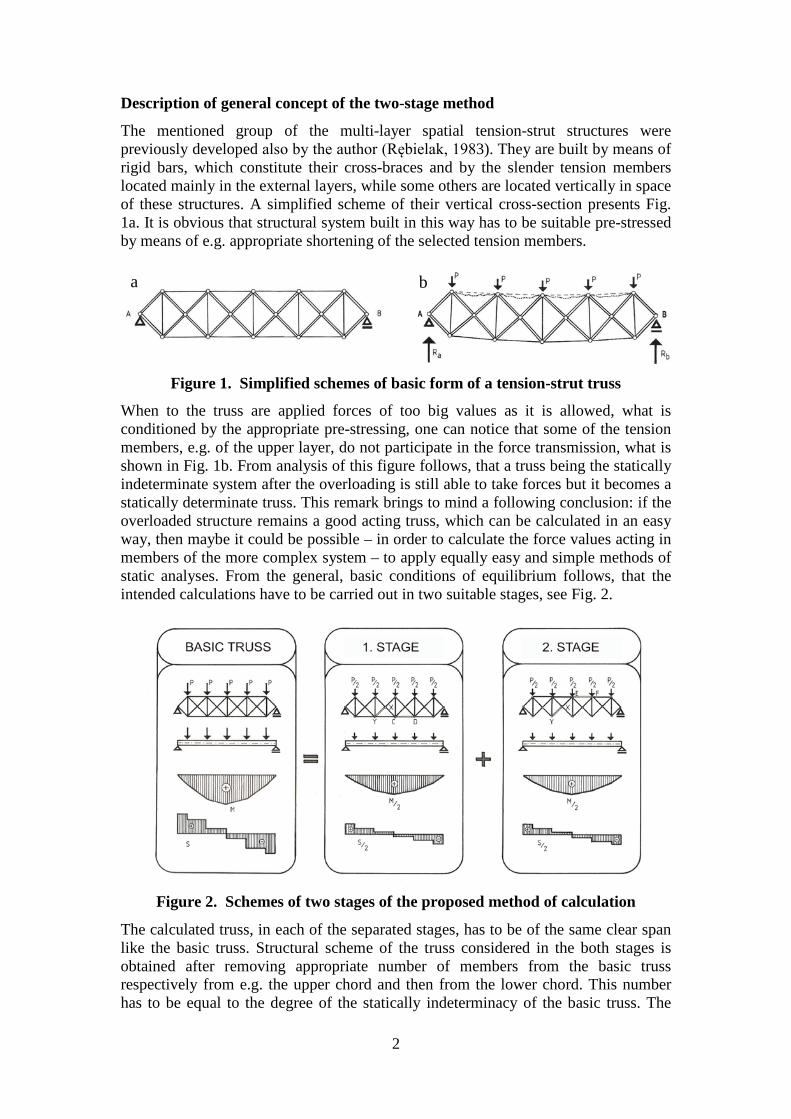
Description of general concept of the two-stage method
The mentioned group of the multi-layer spatial tension-strut structures were previously developed also by the author (Rębielak, 1983). They are built by means of rigid bars, which constitute their cross-braces and by the slender tension members located mainly in the external layers, while some others are located vertically in space of these structures. A simplified scheme of their vertical cross-section presents Fig. 1a. It is obvious that structural system built in this way has to be suitable pre-stressed by means of e.g. appropriate shortening of the selected tension members.
Figure 1. Simplified schemes of basic form of a tension-strut truss
When to the truss are applied forces of too big values as it is allowed, what is conditioned by the appropriate pre-stressing, one can notice that some of the tension members, e.g. of the upper layer, do not participate in the force transmission, what is shown in Fig. 1b. From analysis of this figure follows, that a truss being the statically indeterminate system after the overloading is still able to take forces but it becomes a statically determinate truss. This remark brings to mind a following conclusion: if the overloaded structure remains a good acting truss, which can be calculated in an easy way, then maybe it could be possible – in order to calculate the force values acting in members of the more complex system – to apply equally easy and simple methods of static analyses. From the general, basic conditions of equilibrium follows, that the intended calculations have to be carried out in two suitable stages, see Fig. 2.
Figure 2. Schemes of two stages of the proposed method of calculation
The calculated truss, in each of the separated stages, has to be of the same clear span like the basic truss. Structural scheme of the truss considered in the both stages is obtained after removing appropriate number of members from the basic truss respectively from e.g. the upper chord and then from the lower chord. This number has to be equal to the degree of the statically indeterminacy of the basic truss. The
a b

3
considered trusses in each stage have to be loaded by the forces two times smaller than forces applied to the basic truss. These forces should be applied to nodes of the same positions like in the basic truss. Below are presented results of successive calculations carried out for an exemplary basic truss shown in Fig. 2, having the clear span equals 5.00 meters and loaded by single forces of value equal to 1,00 kN applied to nodes of the upper chord. Length of each vertical member of this truss is equal to 1.00 meter. Results of the first stage of calculations are shown in Fig. 3, results of the second stage are presented in Fig. 4 while the final results are displayed in Fig. 5.
Figure 3. Arrangement of force values calculated in the first stage
Figure 4. Arrangement of force values calculated in the second stage
Figure 5. Values of forces obtained as a result of appropriate application of principle of superposition in the proposed two-stage method of calculation
The final values of forces acting in particular cross-braces are defined by sum up the suitable values obtained in each stage. For instance the final value - 0,30 kN of force acting in the cross brace KD, see Fig. 5, is a resultant of force – 2,24 kN calculated for the same member in the first stage, compare Fig. 3, and the value + 1,94 kN calculated for this member in the second stage, compare Fig. 4. Forces acting in

4
members of the lower chord are defined during the first stage of this method because they are removed in the second stage and in this case it is assumed, that in the second stage they are subjected to act forces of values equal to zero. It means that vector of the resultant force, which acts e.g. in member CD and equals + 3,00 kN, see Fig. 5, is determined for the same member in the first stage of calculation, compare Fig. 3, because the force vector obtained in the second stage is equal to zero. Similar remarks refer to the final values of forces defined in this two-stage method for members of the upper and lower chords of the considered sample of this simple truss.
Comparison of results obtained in two different methods
In order to compare the force values calculated in the proposed two-stage method with values of forces determined in one of the methods considered as giving in result the exact force values there were undertaken two parallel calculations of the same statically indeterminate truss, scheme of which is shown in Fig. 6.
Figure 6. Scheme of a plane statically indeterminate truss calculated in two
compared methods
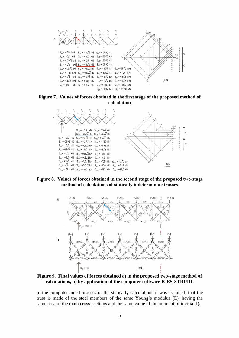
In the both calculations the basic truss is of the same statically scheme, it’s clear span equals 10.00 meters, the construction depth is equal to 1.00 meter and the same load forces are applied to nodes of exactly the same positions. As previously the load forces have the unit value equals 1,00 kN. The considered truss is built by the number of nodes “w” equals 35 and the number of members “p” equal to 78. Condition of the inner statically determinacy p = 2 x w - 3 (1) defines, that a plane truss consists of w = 35 nodes has to be built by means of the following number of members 67 = 2 x 35 - 3 . (2) It implies, that the basic truss is the eleven-fold statically indeterminate system. It means that in the first stage of the proposed method eleven members of e.g. the upper chord have to be removed in order to make this truss a statically determinate system. Because the truss is of symmetric shape and it is symmetrically loaded therefore process of calculations can be carried out only for its half. Results of the first stage of calculations, obtained by application of the Cremona’s method, are shown in Fig. 7, while results determined in the second stage are presented in Fig. 8. The computer software ICES-STRUDL was applied for calculation of the statically indeterminate truss of scheme shown in Fig. 6, (Rębielak and Beranek and Hobbelman, 1985b). Final results of both compared methods are presented for a half of the truss in Fig. 9.
5
Figure 7. Values of forces obtained in the first stage of the proposed method of
calculation
Figure 8. Values of forces obtained in the second stage of the proposed two-stage
method of calculations of statically indeterminate trusses
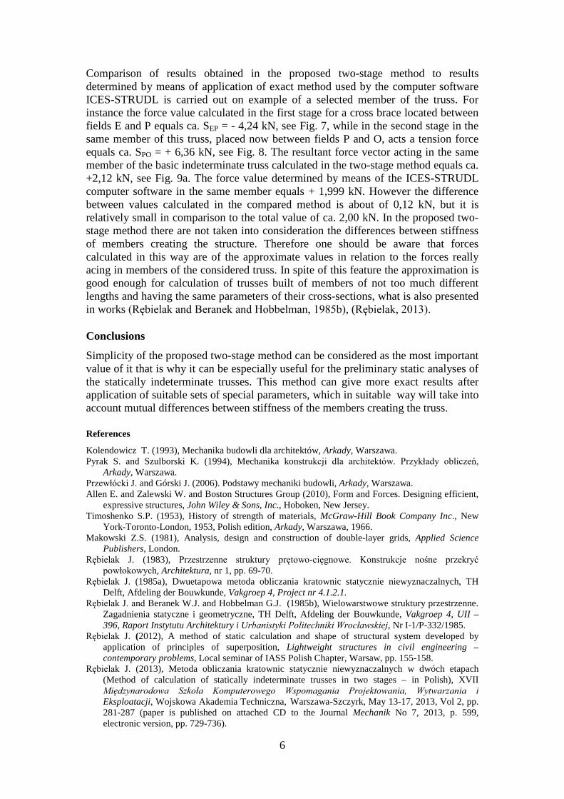
Figure 9. Final values of forces obtained a) in the proposed two-stage method of
calculations, b) by application of the computer software ICES-STRUDL In the computer aided process of the statically calculations it was assumed, that the truss is made of the steel members of the same Young’s modulus (E), having the same area of the main cross-sections and the same value of the moment of inertia (I).
a
b
6
Comparison of results obtained in the proposed two-stage method to results determined by means of application of exact method used by the computer software ICES-STRUDL is carried out on example of a selected member of the truss. For instance the force value calculated in the first stage for a cross brace located between fields E and P equals ca. SEP = - 4,24 kN, see Fig. 7, while in the second stage in the same member of this truss, placed now between fields P and O, acts a tension force equals ca. SPO = + 6,36 kN, see Fig. 8. The resultant force vector acting in the same member of the basic indeterminate truss calculated in the two-stage method equals ca. +2,12 kN, see Fig. 9a. The force value determined by means of the ICES-STRUDL computer software in the same member equals + 1,999 kN. However the difference between values calculated in the compared method is about of 0,12 kN, but it is relatively small in comparison to the total value of ca. 2,00 kN. In the proposed two-stage method there are not taken into consideration the differences between stiffness of members creating the structure. Therefore one should be aware that forces calculated in this way are of the approximate values in relation to the forces really acing in members of the considered truss. In spite of this feature the approximation is good enough for calculation of trusses built of members of not too much different lengths and having the same parameters of their cross-sections, what is also presented in works (Rębielak and Beranek and Hobbelman, 1985b), (Rębielak, 2013).
Conclusions
Simplicity of the proposed two-stage method can be considered as the most important value of it that is why it can be especially useful for the preliminary static analyses of the statically indeterminate trusses. This method can give more exact results after application of suitable sets of special parameters, which in suitable way will take into account mutual differences between stiffness of the members creating the truss.
References
Kolendowicz T. (1993), Mechanika budowli dla architektów, Arkady, Warszawa. Pyrak S. and Szulborski K. (1994), Mechanika konstrukcji dla architektów. Przykłady obliczeń,
Arkady, Warszawa. Przewłócki J. and Górski J. (2006). Podstawy mechaniki budowli, Arkady, Warszawa. Allen E. and Zalewski W. and Boston Structures Group (2010), Form and Forces. Designing efficient,
expressive structures, John Wiley & Sons, Inc., Hoboken, New Jersey. Timoshenko S.P. (1953), History of strength of materials, McGraw-Hill Book Company Inc., New
York-Toronto-London, 1953, Polish edition, Arkady, Warszawa, 1966. Makowski Z.S. (1981), Analysis, design and construction of double-layer grids, Applied Science
Publishers, London. Rębielak J. (1983), Przestrzenne struktury prętowo-cięgnowe. Konstrukcje nośne przekryć
powłokowych, Architektura, nr 1, pp. 69-70. Rębielak J. (1985a), Dwuetapowa metoda obliczania kratownic statycznie niewyznaczalnych, TH
Delft, Afdeling der Bouwkunde, Vakgroep 4, Project nr 4.1.2.1. Rębielak J. and Beranek W.J. and Hobbelman G.J. (1985b), Wielowarstwowe struktury przestrzenne.
Zagadnienia statyczne i geometryczne, TH Delft, Afdeling der Bouwkunde, Vakgroep 4, UII – 396, Raport Instytutu Architektury i Urbanistyki Politechniki Wrocławskiej, Nr I-1/P-332/1985.
Rębielak J. (2012), A method of static calculation and shape of structural system developed by application of principles of superposition, Lightweight structures in civil engineering – contemporary problems, Local seminar of IASS Polish Chapter, Warsaw, pp. 155-158.
Rębielak J. (2013), Metoda obliczania kratownic statycznie niewyznaczalnych w dwóch etapach (Method of calculation of statically indeterminate trusses in two stages – in Polish), XVII Międzynarodowa Szkoła Komputerowego Wspomagania Projektowania, Wytwarzania i Eksploatacji, Wojskowa Akademia Techniczna, Warszawa-Szczyrk, May 13-17, 2013, Vol 2, pp. 281-287 (paper is published on attached CD to the Journal Mechanik No 7, 2013, p. 599, electronic version, pp. 729-736).