SIMOTION with SINAMICS S120 Safety Integrated Extended ... · Function example No....
69
Function example No. MC-FE-I-008-V11-EN SIMOTION with SINAMICS S120 Safety Integrated Extended Functions Fail-safe drives connected to SIMOTION D435 Controlled with PROFIsafe via PROFIBUS
Transcript of SIMOTION with SINAMICS S120 Safety Integrated Extended ... · Function example No....
Function example No. MC-FE-I-008-V11-EN
SIMOTION with SINAMICS S120 Safety Integrated Extended Functions
Fail-safe drives connected to SIMOTION D435 Controlled with PROFIsafe via PROFIBUS
SIMOTION with SINAMICS S120 Fail-safe drives Entry ID: 36489289
I DT Safety Integrated Page 2/69 MC-FE-I-008-V11-EN
Cop
yrig
ht ©
Sie
men
s A
G 2
009
All
right
s re
serv
ed
3648
9289
_mc_
fe_i
_008
_V11
_en.
doc
Preliminary remarks Functional examples for the topic "Safety Integrated" are fully-functioning and tested automation configurations based on standard I DT & IA products for simple, fast and low-cost implementation of automation tasks in safety engineering. Each of the functional examples presented deals with sub-task of a typical problem that customers are frequently confronted with in safety engineering.
Besides listing all the necessary software and hardware components, and describing their interconnection, the functional examples also include tested and commented code. This means that the functions described here can be set up within a short time and can thus be used as the basis for expanded and adapted solutions.
Important Note The safety function examples are non-binding and do not claim to be com-plete in respect of configuration, equipment or any type of contingency. The safety function examples are not customer-specific solutions but are only intended to provide support in implementing typical tasks. You are respon-sible for the correct operation of the products described.
These safety function examples do not relieve you of the obligation to use the products safely during application, installation, operation and mainte-nance. By using these safety function examples, you acknowledge the fact that Siemens cannot be held liable for any claims or damages above and beyond the liability described above. We reserve the right to make changes to these safety function examples at any time without prior notice. For de-viations between the recommendations in these safety function examples and other Siemens publications - e.g. Catalogs - then the contents of the other documentation have priority.
SIMOTION with SINAMICS S120 Fail-safe drives Entry ID: 36489289
I DT Safety Integrated Page 3/69 MC-FE-I-008-V11-EN
Cop
yrig
ht ©
Sie
men
s A
G 2
009
All
right
s re
serv
ed
3648
9289
_mc_
fe_i
_008
_V11
_en.
doc
Contents
1 Warranty conditions, liability, and support.................................................. 5
2 Automation function....................................................................................... 6 2.1 Description of the function example.................................................................. 6 2.2 Advantages / customer benefits ....................................................................... 9
3 Required components.................................................................................. 10 3.1 Hardware components.................................................................................... 10 3.2 Software components ..................................................................................... 11 3.2.1 Engineering software ...................................................................................... 11 3.2.2 Firmware......................................................................................................... 11
4 Configuration and wiring ............................................................................. 12 4.1 Overview of the hardware configuration ......................................................... 12 4.2 Wiring of the hardware components ............................................................... 12 4.2.1 Wiring the control voltage ............................................................................... 12 4.2.2 DRIVE-CLiQ interconnection .......................................................................... 13 4.3 Important settings of the hardware components............................................. 14 4.3.1 Bus interfaces ................................................................................................. 14 4.3.2 Bus topology ................................................................................................... 16
5 Overview and operation ............................................................................... 17 5.1 Description of operation.................................................................................. 17 5.2 Summary of the input signals ......................................................................... 19
6 Example project ............................................................................................ 20 6.1 Passwords ...................................................................................................... 20 6.2 Basic configuration ......................................................................................... 21 6.2.1 Hardware configuration of the fail-safe SIMATIC control................................ 21 6.2.2 Inserting SIMOTION into the existing SIMATIC project .................................. 27 6.2.3 Basic commissioning of the SINAMICS drives (without safety) ...................... 30 6.2.4 Configuring the message frame...................................................................... 35 6.2.5 Inserting SIMOTION in HW Config F-CPU and coupling................................ 37 6.3 Programming the fail-safe control ................................................................... 42 6.4 Parameterizing the safety functions in SINAMICS Integrated ........................ 47 6.4.1 Configuring the safety functions in the drives ................................................. 47 6.4.2 Configuring the safety data block on the SINAMICS side .............................. 51 6.5 SIMOTION ...................................................................................................... 53 6.5.1 Creating SIMOTION axes............................................................................... 53 6.5.2 SIMOTION programs...................................................................................... 61 6.5.3 Configuration of the execution system............................................................ 64 6.5.4 SIMOTION messages..................................................................................... 66 6.6 Download of the project example ................................................................... 66 6.6.1 Downloading the S7-F-CPU project configuration .......................................... 66 6.6.2 Downloading the project configuration of SIMOTION and SINAMICS
Integrated........................................................................................................ 68
SIMOTION with SINAMICS S120 Fail-safe drives Entry ID: 36489289
I DT Safety Integrated Page 4/69 MC-FE-I-008-V11-EN
Cop
yrig
ht ©
Sie
men
s A
G 2
009
All
right
s re
serv
ed
3648
9289
_mc_
fe_i
_008
_V11
_en.
doc
6.7 Acceptance test .............................................................................................. 69
7 History ........................................................................................................... 69
SIMOTION with SINAMICS S120 Fail-safe drives Entry ID: 36489289
I DT Safety Integrated Page 5/69 MC-FE-I-008-V11-EN
Cop
yrig
ht ©
Sie
men
s A
G 2
009
All
right
s re
serv
ed
3648
9289
_mc_
fe_i
_008
_V11
_en.
doc
1 Warranty conditions, liability, and support
Siemens shall not be held liable for the information provided in this docu-ment.
We accept no liability for any damage or loss caused by the examples, in-formation, programs, planning data, or performance data described in this safety function example, irrespective of the legal basis for claims arising from such damage or loss, unless liability is mandatory (for example, in ac-cordance with the German Product Liability Act in cases of intent, gross negligence, due to endangerment of life, the body or health, due to as-sumption of a guarantee for a product's characteristics of state, due to ma-licious concealment of a defect, or due to violation of basic contractual obli-gations). Any compensation for violation of basic contractual obligations, however, shall be limited to the foreseeable damage or loss which is typi-cally envisaged in contracts unless there has been gross negligence or un-less liability is mandatory due to endangerment of life, the body, or health. Any change to the burden of proof to your disadvantage is not covered he-reby.
Copyright© 2009 Siemens I DT. Reproduction or transmission of these ap-plication examples or extracts thereof are forbidden without the express written authority of Siemens I DT.
If you have any questions about this article, please send an e-mail to the following address: [email protected]
SIMOTION with SINAMICS S120 Fail-safe drives Entry ID: 36489289
I DT Safety Integrated Page 6/69 MC-FE-I-008-V11-EN
Cop
yrig
ht ©
Sie
men
s A
G 2
009
All
right
s re
serv
ed
3648
9289
_mc_
fe_i
_008
_V11
_en.
doc
2 Automation function
2.1 Description of the function example
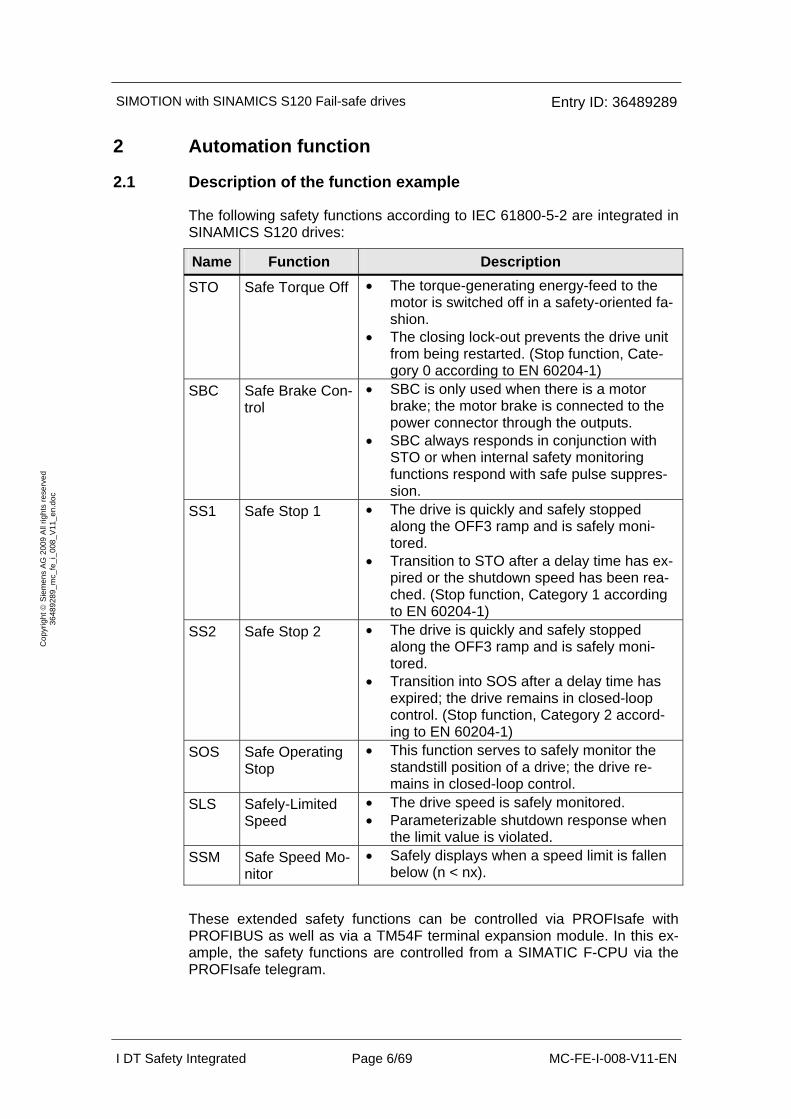
The following safety functions according to IEC 61800-5-2 are integrated in SINAMICS S120 drives:
Name Function Description
STO Safe Torque Off • The torque-generating energy-feed to the motor is switched off in a safety-oriented fa-shion.
• The closing lock-out prevents the drive unit from being restarted. (Stop function, Cate-gory 0 according to EN 60204-1)
SBC Safe Brake Con-trol
• SBC is only used when there is a motor brake; the motor brake is connected to the power connector through the outputs.
• SBC always responds in conjunction with STO or when internal safety monitoring functions respond with safe pulse suppres-sion.
SS1 Safe Stop 1 • The drive is quickly and safely stopped along the OFF3 ramp and is safely moni-tored.
• Transition to STO after a delay time has ex-pired or the shutdown speed has been rea-ched. (Stop function, Category 1 according to EN 60204-1)
SS2 Safe Stop 2 • The drive is quickly and safely stopped along the OFF3 ramp and is safely moni-tored.
• Transition into SOS after a delay time has expired; the drive remains in closed-loop control. (Stop function, Category 2 accord-ing to EN 60204-1)
SOS Safe Operating Stop
• This function serves to safely monitor the standstill position of a drive; the drive re-mains in closed-loop control.
SLS Safely-Limited Speed
• The drive speed is safely monitored. • Parameterizable shutdown response when
the limit value is violated. SSM Safe Speed Mo-
nitor • Safely displays when a speed limit is fallen
below (n < nx).
These extended safety functions can be controlled via PROFIsafe with PROFIBUS as well as via a TM54F terminal expansion module. In this ex-ample, the safety functions are controlled from a SIMATIC F-CPU via the PROFIsafe telegram.
SIMOTION with SINAMICS S120 Fail-safe drives Entry ID: 36489289
I DT Safety Integrated Page 7/69 MC-FE-I-008-V11-EN
Cop
yrig
ht ©
Sie
men
s A
G 2
009
All
right
s re
serv
ed
3648
9289
_mc_
fe_i
_008
_V11
_en.
doc
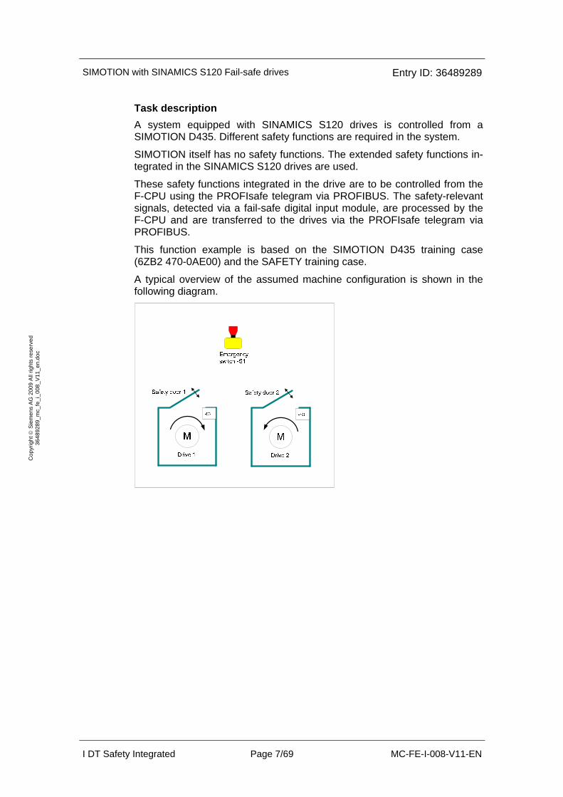
Task description A system equipped with SINAMICS S120 drives is controlled from a SIMOTION D435. Different safety functions are required in the system.
SIMOTION itself has no safety functions. The extended safety functions in-tegrated in the SINAMICS S120 drives are used.
These safety functions integrated in the drive are to be controlled from the F-CPU using the PROFIsafe telegram via PROFIBUS. The safety-relevant signals, detected via a fail-safe digital input module, are processed by the F-CPU and are transferred to the drives via the PROFIsafe telegram via PROFIBUS.
This function example is based on the SIMOTION D435 training case (6ZB2 470-0AE00) and the SAFETY training case.
A typical overview of the assumed machine configuration is shown in the following diagram.

SIMOTION with SINAMICS S120 Fail-safe drives Entry ID: 36489289
I DT Safety Integrated Page 8/69 MC-FE-I-008-V11-EN
Cop
yrig
ht ©
Sie
men
s A
G 2
009
All
right
s re
serv
ed
3648
9289
_mc_
fe_i
_008
_V11
_en.
doc
The following safety functions are used as basis for further consideration.
Safety function Description Response
SF1 The Emergency Stop button is actuated.
Drive 1 is quickly stopped in a controlled fashion -> subse-quent pulse suppression (SS1)
Drive 2 is stopped with imme-diate pulse suppression (STO)
SF2
Opening safety door 1 while Drive 1 is turning, Drive 1 should be stopped quickly due to the violation of safety condi-tion. After Drive 1 is stopped with speed setpoint = 0 the standstill position is safely monitored.
The SIMOTION brakes drive 1 in the closed-loop position con-trolled mode. The standstill position is safely monitored (SOS) after a delay time has expired.
SF3 When safety door 2 is open, Drive 2 must not exceed the user defined safe speed.
The speed of drive 2 is moni-tored (SLS)
Solution Hardware overview
This function example shows how the STO, SS1, SOS and SLS safety functions are controlled via the PROFIsafe telegram at a SIMOTION D435 with a SINAMICS S120 drive group.
The drive line-up in the booksize format comprises an infeed and a Double Motor Module. A SIMOTION D435 is used for the closed-loop motion con-trol and closed-loop motor control. The two servomotors, which are inde-pendent of one another, are controlled from the Double Motor Module. A Smart Line Module is used as infeed.
SIMOTION with SINAMICS S120 Fail-safe drives Entry ID: 36489289
I DT Safety Integrated Page 9/69 MC-FE-I-008-V11-EN
Cop
yrig
ht ©
Sie
men
s A
G 2
009
All
right
s re
serv
ed
3648
9289
_mc_
fe_i
_008
_V11
_en.
doc
The safety-relevant signals are sensed using fail-safe inputs of the ET200M and logically processed in the F-CPU. From the fail-safe data, the F-CPU generates a PROFIsafe telegram for each drive. This is transferred to the SINAMICS drives via PROFIBUS where it controls the safety functions.
When Emergency Stop is initiated, drive 1 is stopped using the SS1 func-tion integrated in the drive and drive 2 is stopped with STO.
The other two switches (-S2 and -S3) in the Safety training case each simu-late a safety door for drive 1 and 2. If safety door 1 is opened, then SIMOTION brakes drive 1 down to standstill (zero speed). After a configur-able safe delay time has expired, the standstill position is safely monitored (the SOS function is selected). When the door is closed, axis 1 restarts (the SOS function is deselected). When safety door 2 is opened, the speed of drive 2 is monitored against an user defined safe speed setpoint value in both directions (SLS function). The setpoint speed is limited to 80% of the selected SLS stage, where up to 4 SLS stages can be defined and se-lected. The speed limit is withdrawn if the simulated door is closed again. The other drive is not influenced.
2.2 Advantages / customer benefits
• The safety functions integrated in the drive are simply controlled.
• Simple design using standard technology.
• The existing system can be quickly and simply expanded.
• Space-saving and favorably-priced design using integrated safety functions – additional hardware is not required.
• User-friendly evaluation and diagnostic information is available in the SIMOTION system.
• Other safety concepts can be realized using this as basis.
SIMOTION with SINAMICS S120 Fail-safe drives Entry ID: 36489289
I DT Safety Integrated Page 10/69 MC-FE-I-008-V11-EN
Cop
yrig
ht ©
Sie
men
s A
G 2
009
All
right
s re
serv
ed
3648
9289
_mc_
fe_i
_008
_V11
_en.
doc
3 Required components
The hardware components and software versions required in this function example are listed in this chapter.
3.1 Hardware components
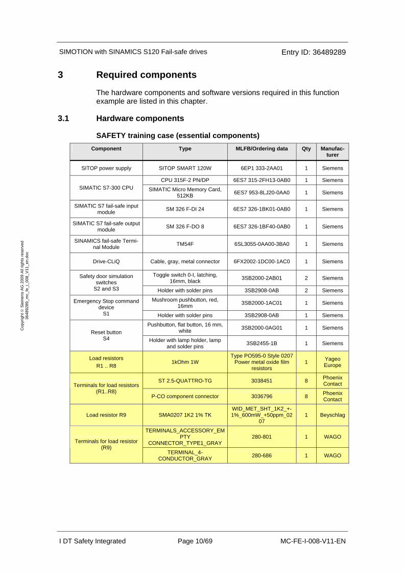
SAFETY training case (essential components) Component Type MLFB/Ordering data Qty Manufac-
turer
SITOP power supply SITOP SMART 120W 6EP1 333-2AA01 1 Siemens
CPU 315F-2 PN/DP 6ES7 315-2FH13-0AB0 1 Siemens SIMATIC S7-300 CPU SIMATIC Micro Memory Card,
512KB 6ES7 953-8LJ20-0AA0 1 Siemens
SIMATIC S7 fail-safe input module SM 326 F-DI 24 6ES7 326-1BK01-0AB0 1 Siemens
SIMATIC S7 fail-safe output module SM 326 F-DO 8 6ES7 326-1BF40-0AB0 1 Siemens
SINAMICS fail-safe Termi-nal Module TM54F 6SL3055-0AA00-3BA0 1 Siemens
Drive-CLiQ Cable, gray, metal connector 6FX2002-1DC00-1AC0 1 Siemens
Toggle switch 0-I, latching, 16mm, black 3SB2000-2AB01 2 Siemens Safety door simulation
switches S2 and S3 Holder with solder pins 3SB2908-0AB 2 Siemens
Mushroom pushbutton, red, 16mm 3SB2000-1AC01 1 Siemens Emergency Stop command
device S1 Holder with solder pins 3SB2908-0AB 1 Siemens
Pushbutton, flat button, 16 mm, white 3SB2000-0AG01 1 Siemens
Reset button S4 Holder with lamp holder, lamp
and solder pins 3SB2455-1B 1 Siemens
Load resistors R1 .. R8
1kOhm 1W Type PO595-0 Style 0207
Power metal oxide film resistors
1 Yageo Europe
ST 2.5-QUATTRO-TG 3038451 8 Phoenix Contact Terminals for load resistors
(R1..R8) P-CO component connector 3036796 8 Phoenix
Contact
Load resistor R9 SMA0207 1K2 1% TK WID_MET_SHT_1K2_+-1%_600mW_+50ppm_02
07 1 Beyschlag
TERMINALS_ACCESSORY_EMPTY
CONNECTOR_TYPE1_GRAY 280-801 1 WAGO
Terminals for load resistor (R9)
TERMINAL_4-CONDUCTOR_GRAY 280-686 1 WAGO
SIMOTION with SINAMICS S120 Fail-safe drives Entry ID: 36489289
I DT Safety Integrated Page 11/69 MC-FE-I-008-V11-EN
Cop
yrig
ht ©
Sie
men
s A
G 2
009
All
right
s re
serv
ed
3648
9289
_mc_
fe_i
_008
_V11
_en.
doc
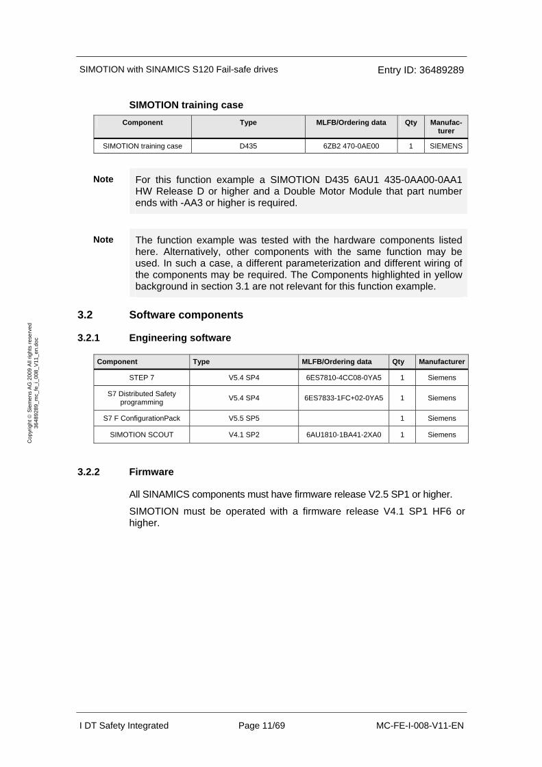
SIMOTION training case Component Type MLFB/Ordering data Qty Manufac-
turer
SIMOTION training case D435 6ZB2 470-0AE00 1 SIEMENS
Note For this function example a SIMOTION D435 6AU1 435-0AA00-0AA1 HW Release D or higher and a Double Motor Module that part number ends with -AA3 or higher is required.
Note The function example was tested with the hardware components listed here. Alternatively, other components with the same function may be used. In such a case, a different parameterization and different wiring of the components may be required. The Components highlighted in yellow background in section 3.1 are not relevant for this function example.
3.2 Software components
3.2.1 Engineering software
Component Type MLFB/Ordering data Qty Manufacturer
STEP 7 V5.4 SP4 6ES7810-4CC08-0YA5 1 Siemens
S7 Distributed Safety programming V5.4 SP4 6ES7833-1FC+02-0YA5 1 Siemens
S7 F ConfigurationPack V5.5 SP5 1 Siemens
SIMOTION SCOUT V4.1 SP2 6AU1810-1BA41-2XA0 1 Siemens
3.2.2 Firmware
All SINAMICS components must have firmware release V2.5 SP1 or higher.
SIMOTION must be operated with a firmware release V4.1 SP1 HF6 or higher.
SIMOTION with SINAMICS S120 Fail-safe drives Entry ID: 36489289
I DT Safety Integrated Page 12/69 MC-FE-I-008-V11-EN
Cop
yrig
ht ©
Sie
men
s A
G 2
009
All
right
s re
serv
ed
3648
9289
_mc_
fe_i
_008
_V11
_en.
doc
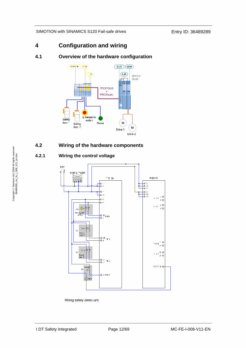
4 Configuration and wiring
4.1 Overview of the hardware configuration
4.2 Wiring of the hardware components
4.2.1 Wiring the control voltage
SIMOTION with SINAMICS S120 Fail-safe drives Entry ID: 36489289
I DT Safety Integrated Page 13/69 MC-FE-I-008-V11-EN
Cop
yrig
ht ©
Sie
men
s A
G 2
009
All
right
s re
serv
ed
3648
9289
_mc_
fe_i
_008
_V11
_en.
doc
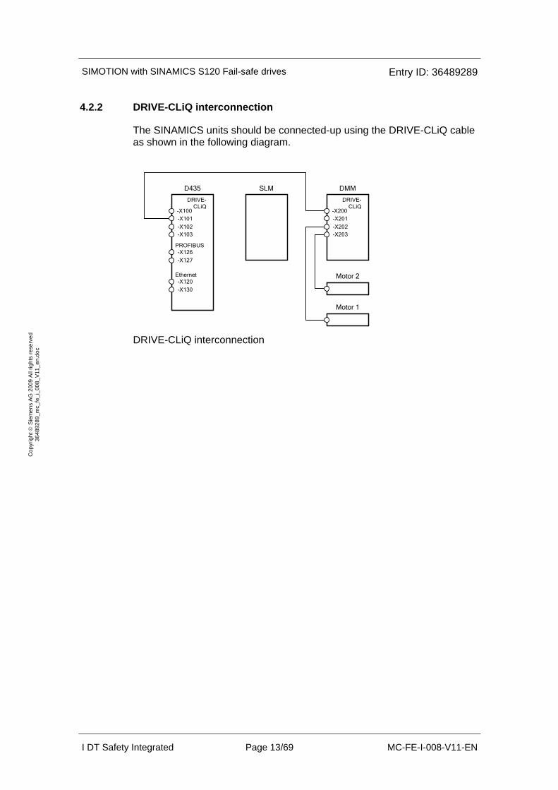
4.2.2 DRIVE-CLiQ interconnection
The SINAMICS units should be connected-up using the DRIVE-CLiQ cable as shown in the following diagram.
D435
DRIVE-CLiQ
-X100-X101
-X102-X103
PROFIBUS
SLM
-X126
DMM
DRIVE-CLiQ
-X200-X201
-X202-X203
Motor 2
Motor 1
-X127
Ethernet-X120
-X130
DRIVE-CLiQ interconnection

SIMOTION with SINAMICS S120 Fail-safe drives Entry ID: 36489289
I DT Safety Integrated Page 14/69 MC-FE-I-008-V11-EN
Cop
yrig
ht ©
Sie
men
s A
G 2
009
All
right
s re
serv
ed
3648
9289
_mc_
fe_i
_008
_V11
_en.
doc
4.3 Important settings of the hardware components
In this example, PROFIBUS is used to control the safety functions in the drives. For this purpose, using the PROFIsafe telegram, control and status signals are exchanged between the drives and the F-CPU. SIMOTION does not evaluate these telegrams, it only transfers them (routing).
Further, the F-CPU and the SIMOTION are configured via PROFIBUS.
4.3.1 Bus interfaces
Programming device / PC
• PROFIBUS address = 0
• As the F-CPU used is the bus master, the PROFIBUS interface of the programming device must not be configured as the only master on the bus (do not enter a checkmark in the field "PG/PC is the only master on the bus").

SIMOTION with SINAMICS S120 Fail-safe drives Entry ID: 36489289
I DT Safety Integrated Page 15/69 MC-FE-I-008-V11-EN
Cop
yrig
ht ©
Sie
men
s A
G 2
009
All
right
s re
serv
ed
3648
9289
_mc_
fe_i
_008
_V11
_en.
doc
SIMOTION D435
• PROFIBUS address = 2
• The PROFIBUS address is set via HM Config.
SIMATIC 315F-2 PN/DP CPU
• PROFIBUS address = 4

SIMOTION with SINAMICS S120 Fail-safe drives Entry ID: 36489289
I DT Safety Integrated Page 16/69 MC-FE-I-008-V11-EN
Cop
yrig
ht ©
Sie
men
s A
G 2
009
All
right
s re
serv
ed
3648
9289
_mc_
fe_i
_008
_V11
_en.
doc
4.3.2 Bus topology
View in NetPro
Conditions for operation
• The SIMATIC components have been mounted and connected with one another. The PROFIsafe addresses of the fail-safe input and output modules must be set using the DIL switch; see Chapter 6.2.1.
• All of the components are connected as specified in Chapter 4.2.
• The DRIVE-CLiQ topology of the SINAMICS components has been maintained.
• The motors are connected to the Motor Module using the power and encoder cable.
• The Motor Module is correctly connected with the infeed (DC link and 24 V DC control voltage).
• The infeed is connected to the line supply.
• The components are supplied with 24 V DC.
SIMOTION with SINAMICS S120 Fail-safe drives Entry ID: 36489289
I DT Safety Integrated Page 17/69 MC-FE-I-008-V11-EN
Cop
yrig
ht ©
Sie
men
s A
G 2
009
All
right
s re
serv
ed
3648
9289
_mc_
fe_i
_008
_V11
_en.
doc
5 Overview and operation
5.1 Description of operation
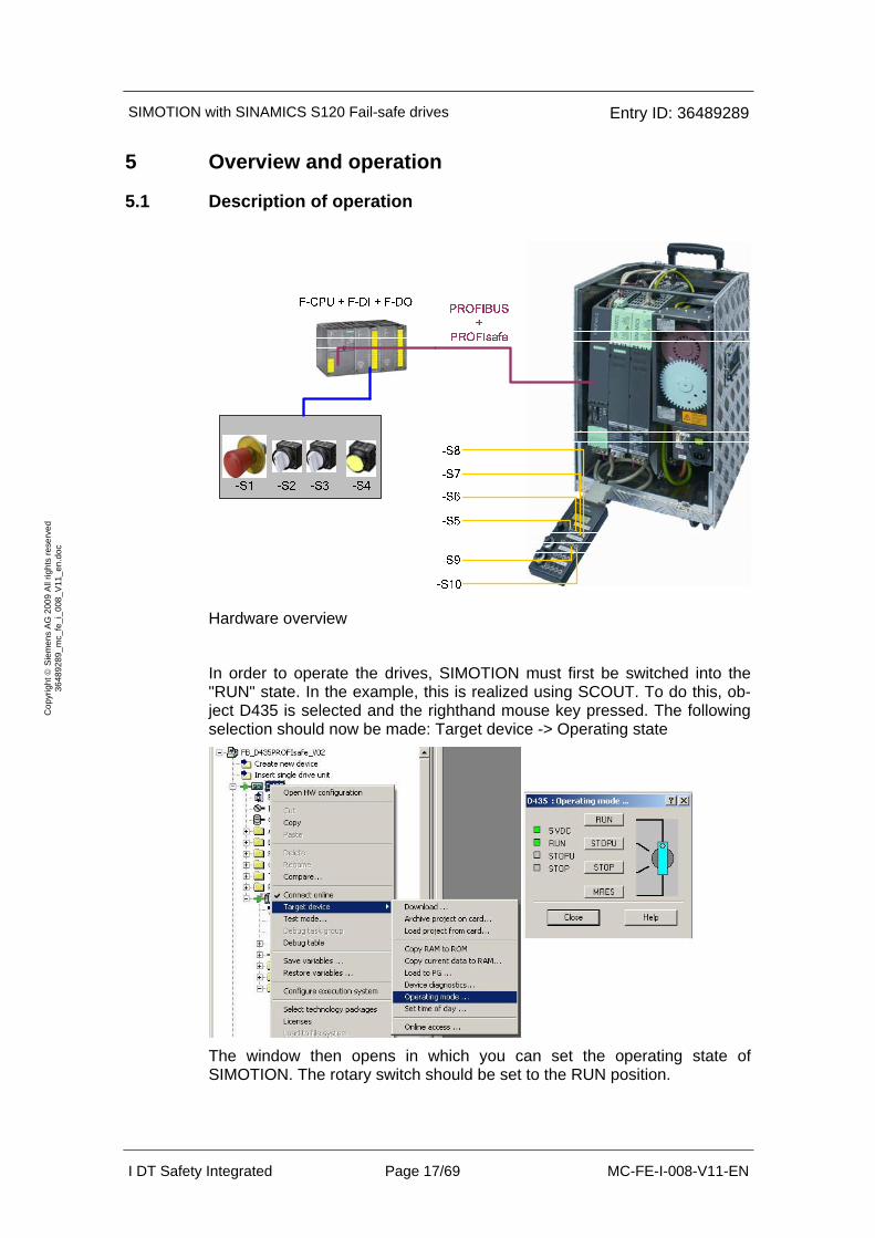
Hardware overview
In order to operate the drives, SIMOTION must first be switched into the "RUN" state. In the example, this is realized using SCOUT. To do this, ob-ject D435 is selected and the righthand mouse key pressed. The following selection should now be made: Target device -> Operating state
The window then opens in which you can set the operating state of SIMOTION. The rotary switch should be set to the RUN position.
SIMOTION with SINAMICS S120 Fail-safe drives Entry ID: 36489289
I DT Safety Integrated Page 18/69 MC-FE-I-008-V11-EN
Cop
yrig
ht ©
Sie
men
s A
G 2
009
All
right
s re
serv
ed
3648
9289
_mc_
fe_i
_008
_V11
_en.
doc
Switches -S1 to -S4 are located on a switchbox that belongs to the Safety training case. The various safety functions are selected using these switches. Switches -S5 to -S10 are located on a switchbox that belongs to the SIMOTION training case. These switches are used to switch axis en-able signals, start travel programs, initiate the test function for the safety functions and acknowledge faults.
The Emergency Stop button S1 must be released in order to be able to op-erate the drives
The axis enable signal for drive 1 (upper/red motor) are switched using switch -S5. The associated travel program can be started and stopped us-ing -S6. For axis 2 (lower/blue motor), -S7 is used to issue the enable sig-nal and the travel program is activated or deactivated with -S8. Pending alarms on the SIMOTION as well as drive alarms can be acknowledged us-ing -S9. The safety alarms are the exception in this case, as they must be acknowledged in a fail-safe fashion using -S4. The test stop to be cyclically executed for the safety functions in the drives is activated using -S10.
If the Emergency Stop pushbutton -S1 is pressed, then for drive 1 (up-per/red motor), safety function SS1 is initiated; i.e. the drive is braked along the OFF3 ramp and then STO is activated. STO is directly initiated for drive 2 (lower/blue motor); i.e. the drive coasts down. When Emergency Stop is initiated, drive 1 comes to a standstill before drive 2.
Drive 1 can be operated when safety door 1 is closed (toggle switch -S2). If -S2 is opened, then safety function SOS is initiated; i.e. SIMOTION brakes the drive down to standstill. The drive standstill position is safely monitored after an user configurable safe timer has expired. If the simulated safety door -S2 is closed again, then the travel program is restarted. In this case, an ON command is not necessary.
Drive 2 can be operated at any speed when safety door 2 is closed (toggle switch -S3). If -S3 is opened, then SIMOTION limits the travel speed to 80% of the speed limit value of stage 1 of safety function SLS. This limit va-lue is monitored by safety function SLS after a defined time has expired. If -S3 is closed again, then SLS is switched-out and the speed limit on the SIMOTION is withdrawn. The drive can now be operated again with the configured speed.

SIMOTION with SINAMICS S120 Fail-safe drives Entry ID: 36489289
I DT Safety Integrated Page 19/69 MC-FE-I-008-V11-EN
Cop
yrig
ht ©
Sie
men
s A
G 2
009
All
right
s re
serv
ed
3648
9289
_mc_
fe_i
_008
_V11
_en.
doc
5.2 Summary of the input signals
Digital inputs of the SINAMICS Integrated at the SIMOTION D435
DI0 -S5 Drive 1 Sets / withdraws axis en-able signals
DI1 -S6 Drive 1 Starts/stops the travel pro-gram
DI2 -S7 Drive 2 Sets / withdraws axis en-able signals
DI3 -S8 Drive 2 Starts/stops the travel pro-gram
DI6 -S9 Drive 1 / Drive 2 / SIMOTION Acknowledges alarms
DI7 -S10 Drive 1 / Drive 2 Initiates a test stop
Fail-safe inputs at the F-DI module
F-DI0 -S1 Emergency Stop button Drive 1: SS1 Drive 2: STO
F-DI1 -S2 Safety door 1 (for drive 1) SOS
F-DI2 -S3 Safety door 2 (for drive 2) SLS
F-DI3 -S4 Acknowledgement button
Fail-safe acknowledge-ment (drive 1 & 2) and depassivation (all F sla-ves)

SIMOTION with SINAMICS S120 Fail-safe drives Entry ID: 36489289
I DT Safety Integrated Page 20/69 MC-FE-I-008-V11-EN
Cop
yrig
ht ©
Sie
men
s A
G 2
009
All
right
s re
serv
ed
3648
9289
_mc_
fe_i
_008
_V11
_en.
doc
6 Example project
In this chapter, you get to know how the individual components must be pa-rameterized. SIMOTION SCOUT is used as the engineering software for SIMOTION and the SINAMICS Integrated. Distributed Safety is a prerequi-site for programming the F-CPU.
This chapter will show in steps how the software project belonging to this function example was set-up.
6.1 Passwords
For reasons of simplicity, in the project, a common safety password is used for the program and hardware on the SIMATIC components. A password is also used when configuring Safety functions for SINAMICS components (drives).
• Safety password on the F-CPU: "0"
• Safety password on SINAMICS components: "1" These passwords should be changed for real applications!
SIMOTION with SINAMICS S120 Fail-safe drives Entry ID: 36489289
I DT Safety Integrated Page 21/69 MC-FE-I-008-V11-EN
Cop
yrig
ht ©
Sie
men
s A
G 2
009
All
right
s re
serv
ed
3648
9289
_mc_
fe_i
_008
_V11
_en.
doc
6.2 Basic configuration
6.2.1 Hardware configuration of the fail-safe SIMATIC control
Description Note
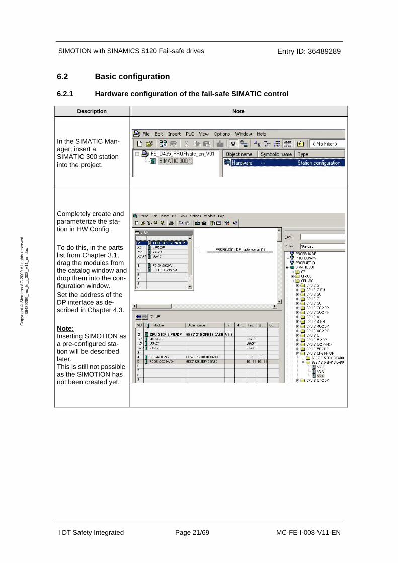
In the SIMATIC Man-ager, insert a SIMATIC 300 station into the project.
Completely create and parameterize the sta-tion in HW Config. To do this, in the parts list from Chapter 3.1, drag the modules from the catalog window and drop them into the con-figuration window. Set the address of the DP interface as de-scribed in Chapter 4.3. Note: Inserting SIMOTION as a pre-configured sta-tion will be described later. This is still not possible as the SIMOTION has not been created yet.
SIMOTION with SINAMICS S120 Fail-safe drives Entry ID: 36489289
I DT Safety Integrated Page 22/69 MC-FE-I-008-V11-EN
Cop
yrig
ht ©
Sie
men
s A
G 2
009
All
right
s re
serv
ed
3648
9289
_mc_
fe_i
_008
_V11
_en.
doc
Description Note
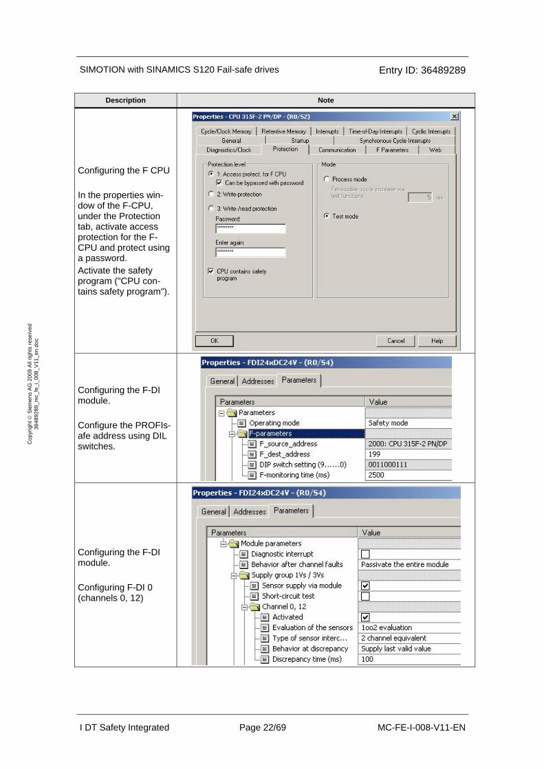
Configuring the F CPU In the properties win-dow of the F-CPU, under the Protection tab, activate access protection for the F-CPU and protect using a password. Activate the safety program ("CPU con-tains safety program").
Configuring the F-DI module. Configure the PROFIs-afe address using DIL switches.
Configuring the F-DI module. Configuring F-DI 0 (channels 0, 12)
SIMOTION with SINAMICS S120 Fail-safe drives Entry ID: 36489289
I DT Safety Integrated Page 23/69 MC-FE-I-008-V11-EN
Cop
yrig
ht ©
Sie
men
s A
G 2
009
All
right
s re
serv
ed
3648
9289
_mc_
fe_i
_008
_V11
_en.
doc
Description Note
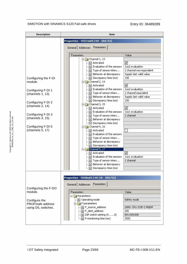
Configuring the F-DI module. Configuring F-DI 1 (channels 1, 13) Configuring F-DI 2 (channels 2, 14) Configuring F-DI 3 (channels 3, 15) Configuring F-DI 5 (channels 5, 17)
Configuring the F-DO module. Configure the PROFIsafe address using DIL switches.

SIMOTION with SINAMICS S120 Fail-safe drives Entry ID: 36489289
I DT Safety Integrated Page 24/69 MC-FE-I-008-V11-EN
Cop
yrig
ht ©
Sie
men
s A
G 2
009
All
right
s re
serv
ed
3648
9289
_mc_
fe_i
_008
_V11
_en.
doc
Description Note
Configuring the F-DO module. Configuring F-DO 7
Save HW Config, com-pile and download into the F-CPU.
The PC must now be inserted in NetPro in order to create the routing information that is necessary to access SINAMICS Integrated online.

SIMOTION with SINAMICS S120 Fail-safe drives Entry ID: 36489289
I DT Safety Integrated Page 25/69 MC-FE-I-008-V11-EN
Cop
yrig
ht ©
Sie
men
s A
G 2
009
All
right
s re
serv
ed
3648
9289
_mc_
fe_i
_008
_V11
_en.
doc
Description Note
Drag the "PC/PG" ob-ject from the "Stations" folder and drop in the work area. Open the Properties window with a "double click".
Select the "Interfaces" tab, then press the "New" button. Select "PROFIBUS" in the following window and confirm with OK.
Now, set the PROFIBUS address of the PG to the value 0 and establish the con-nection using the al-ready configured PROFIBUS (select "PROFIBUS(1)") Confirm the settings with OK.

SIMOTION with SINAMICS S120 Fail-safe drives Entry ID: 36489289
I DT Safety Integrated Page 26/69 MC-FE-I-008-V11-EN
Cop
yrig
ht ©
Sie
men
s A
G 2
009
All
right
s re
serv
ed
3648
9289
_mc_
fe_i
_008
_V11
_en.
doc
Description Note
The interface must now be assigned on the PC/PG. In the example, the computer is equipped with the CP5512 and this interface is to be connected with the "PROFIBUS(1)". The connection is es-tablished using the "Assign" button.
Now, check as to whether the interface has been "activated". Close the window with "OK".
The PG is now avail-able with active inter-face. The project must now be saved, compiled and downloaded into the CPU (to do this, place the focus on the SIMATIC CPU).

SIMOTION with SINAMICS S120 Fail-safe drives Entry ID: 36489289
I DT Safety Integrated Page 27/69 MC-FE-I-008-V11-EN
Cop
yrig
ht ©
Sie
men
s A
G 2
009
All
right
s re
serv
ed
3648
9289
_mc_
fe_i
_008
_V11
_en.
doc
6.2.2 Inserting SIMOTION into the existing SIMATIC project
Description Note
Insert an additional SIMATIC 300 station into the existing object.
Then (if required) re-name the station, e.g. as "SIMOTION D"
SIMOTION with SINAMICS S120 Fail-safe drives Entry ID: 36489289
I DT Safety Integrated Page 28/69 MC-FE-I-008-V11-EN
Cop
yrig
ht ©
Sie
men
s A
G 2
009
All
right
s re
serv
ed
3648
9289
_mc_
fe_i
_008
_V11
_en.
doc
Description Note
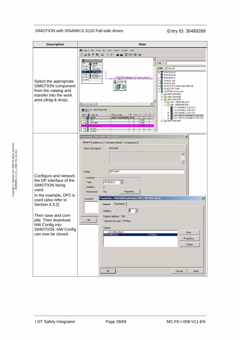
Select the appropriate SIMOTION component from the catalog and transfer into the work area (drag & drop).
Configure and network the DP interface of the SIMOTION being used. In the example, DP2 is used (also refer to Section 4.3.2) Then save and com-pile. Then download HW Config into SIMOTION. HW Config can now be closed.
SIMOTION with SINAMICS S120 Fail-safe drives Entry ID: 36489289
I DT Safety Integrated Page 29/69 MC-FE-I-008-V11-EN
Cop
yrig
ht ©
Sie
men
s A
G 2
009
All
right
s re
serv
ed
3648
9289
_mc_
fe_i
_008
_V11
_en.
doc
Description Note
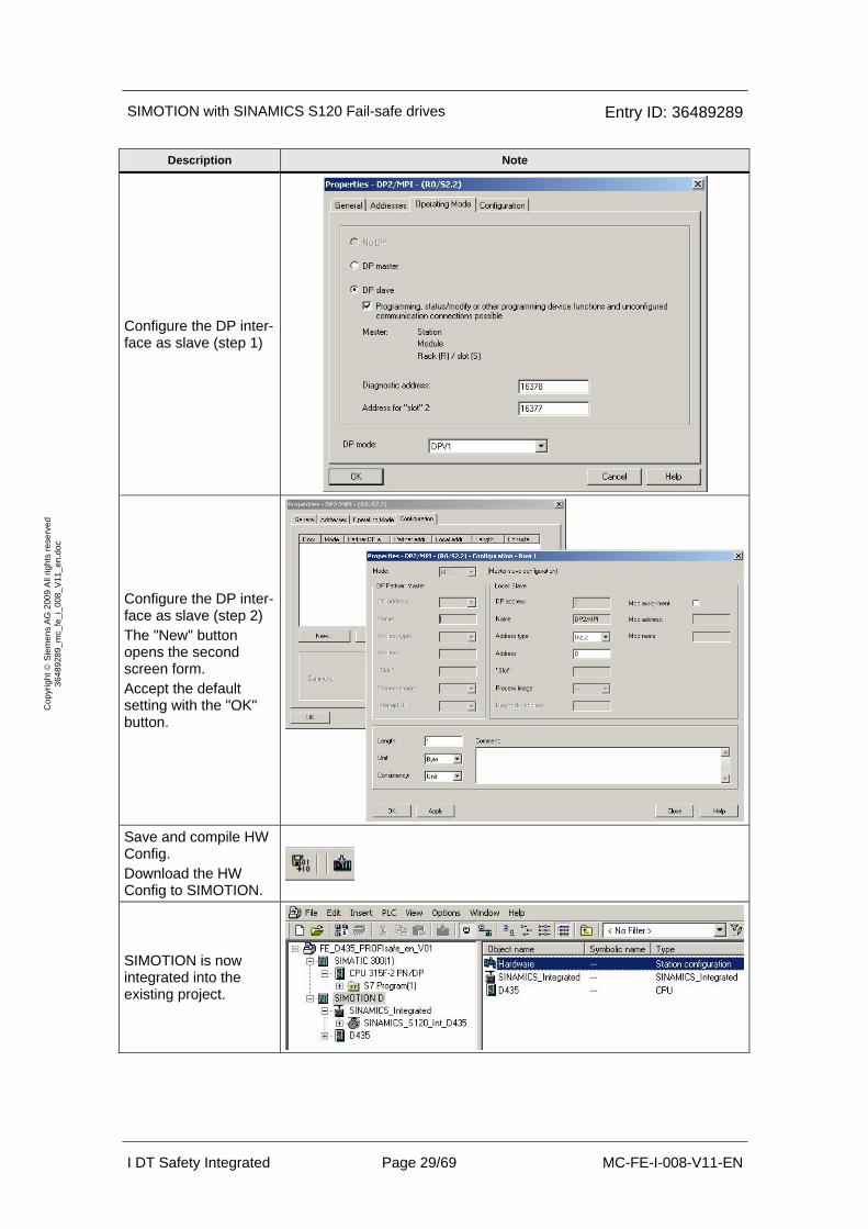
Configure the DP inter-face as slave (step 1)
Configure the DP inter-face as slave (step 2) The "New" button opens the second screen form. Accept the default setting with the "OK" button.
Save and compile HW Config. Download the HW Config to SIMOTION.
SIMOTION is now integrated into the existing project.

SIMOTION with SINAMICS S120 Fail-safe drives Entry ID: 36489289
I DT Safety Integrated Page 30/69 MC-FE-I-008-V11-EN
Cop
yrig
ht ©
Sie
men
s A
G 2
009
All
right
s re
serv
ed
3648
9289
_mc_
fe_i
_008
_V11
_en.
doc
6.2.3 Basic commissioning of the SINAMICS drives (without safety)
Description Note
Open SCOUT / STARTER from the SIMATIC project (-> double click on "Com-missioning")
Go online
Start the automatic configuration of the drives.
Select the "Servo" control type for both drives.
Go offline and "Save and Compile"
SIMOTION with SINAMICS S120 Fail-safe drives Entry ID: 36489289
I DT Safety Integrated Page 31/69 MC-FE-I-008-V11-EN
Cop
yrig
ht ©
Sie
men
s A
G 2
009
All
right
s re
serv
ed
3648
9289
_mc_
fe_i
_008
_V11
_en.
doc
Description Note
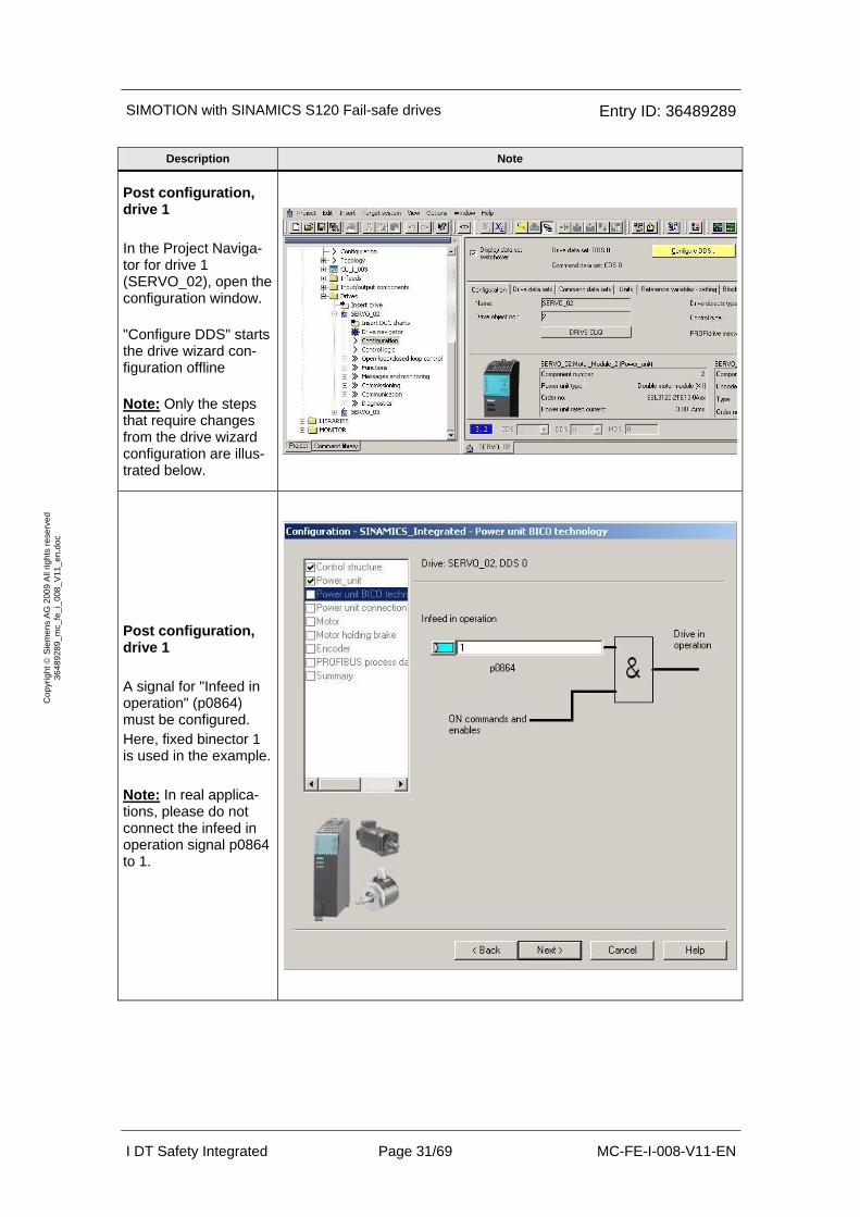
Post configuration, drive 1 In the Project Naviga-tor for drive 1 (SERVO_02), open the configuration window. "Configure DDS" starts the drive wizard con-figuration offline Note: Only the steps that require changes from the drive wizard configuration are illus-trated below.
Post configuration, drive 1 A signal for "Infeed in operation" (p0864) must be configured. Here, fixed binector 1 is used in the example. Note: In real applica-tions, please do not connect the infeed in operation signal p0864 to 1.
SIMOTION with SINAMICS S120 Fail-safe drives Entry ID: 36489289
I DT Safety Integrated Page 32/69 MC-FE-I-008-V11-EN
Cop
yrig
ht ©
Sie
men
s A
G 2
009
All
right
s re
serv
ed
3648
9289
_mc_
fe_i
_008
_V11
_en.
doc
Description Note
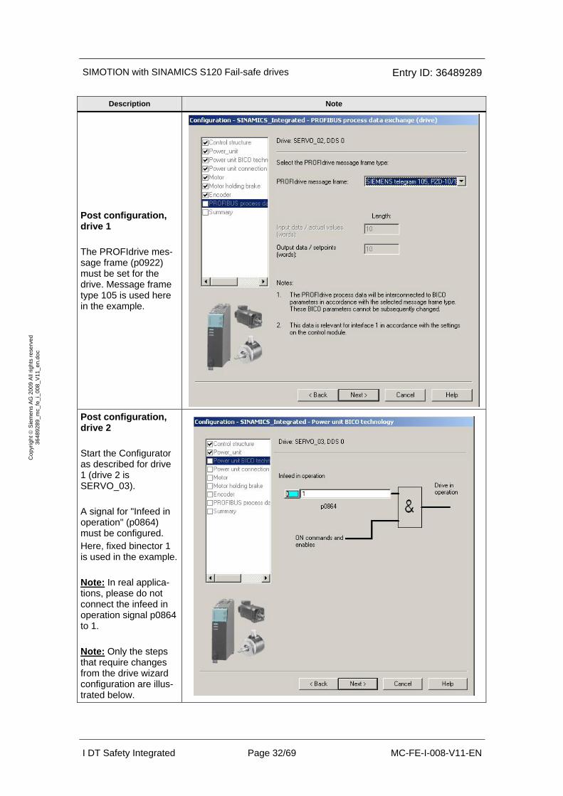
Post configuration, drive 1 The PROFIdrive mes-sage frame (p0922) must be set for the drive. Message frame type 105 is used here in the example.
Post configuration, drive 2 Start the Configurator as described for drive 1 (drive 2 is SERVO_03). A signal for "Infeed in operation" (p0864) must be configured. Here, fixed binector 1 is used in the example. Note: In real applica-tions, please do not connect the infeed in operation signal p0864 to 1. Note: Only the steps that require changes from the drive wizard configuration are illus-trated below.
SIMOTION with SINAMICS S120 Fail-safe drives Entry ID: 36489289
I DT Safety Integrated Page 33/69 MC-FE-I-008-V11-EN
Cop
yrig
ht ©
Sie
men
s A
G 2
009
All
right
s re
serv
ed
3648
9289
_mc_
fe_i
_008
_V11
_en.
doc
Description Note
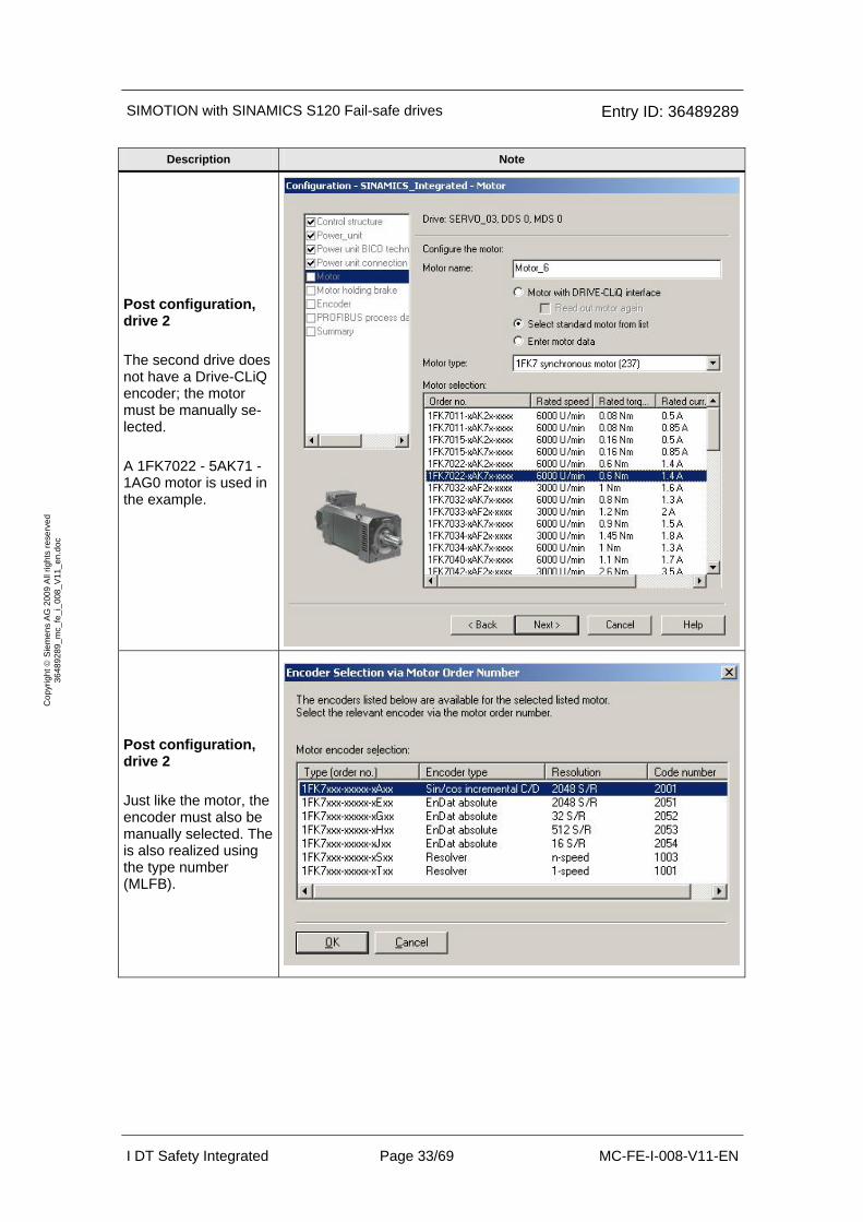
Post configuration, drive 2 The second drive does not have a Drive-CLiQ encoder; the motor must be manually se-lected. A 1FK7022 - 5AK71 - 1AG0 motor is used in the example.
Post configuration, drive 2 Just like the motor, the encoder must also be manually selected. The is also realized using the type number (MLFB).

SIMOTION with SINAMICS S120 Fail-safe drives Entry ID: 36489289
I DT Safety Integrated Page 34/69 MC-FE-I-008-V11-EN
Cop
yrig
ht ©
Sie
men
s A
G 2
009
All
right
s re
serv
ed
3648
9289
_mc_
fe_i
_008
_V11
_en.
doc
Description Note
Post configuration, drive 2 The PROFIdrive mes-sage frame (p0922) must be set for the drive. Message frame type 105 is used here in the example.
Save the configuration, then go online and download the modified project into SINAMICS integrated.
For the SERVO_02 object, open the "Speed controller" window using the Pro-ject Navigator. For both drives, in the example, the speed controller was set as shown here: P gain = 0.1 Nms/rad Reset (integral) time = 10ms

SIMOTION with SINAMICS S120 Fail-safe drives Entry ID: 36489289
I DT Safety Integrated Page 35/69 MC-FE-I-008-V11-EN
Cop
yrig
ht ©
Sie
men
s A
G 2
009
All
right
s re
serv
ed
3648
9289
_mc_
fe_i
_008
_V11
_en.
doc
Description Note
On both drives, sev-eral parameters now have to be adapted in the expert list. Adaptation to 230V operation. Configuring the OFF3 ramp.
Interconnect alarm acknowledgement with -S9 (= DI 6 SINAMICS Integrated).
p2102 = r722.6 in the expert list of the CU
Now copy RAM to ROM (on SINAMICS Integrated), download the project into the PG and save.
6.2.4 Configuring the message frame
Description Note
In SCOUT (offline !), open the window to configure the PROFI-drive message frame
For both drives, create a PROFIsafe slot using the "Insert line" and "PROFIsafe" buttons.

SIMOTION with SINAMICS S120 Fail-safe drives Entry ID: 36489289
I DT Safety Integrated Page 36/69 MC-FE-I-008-V11-EN
Cop
yrig
ht ©
Sie
men
s A
G 2
009
All
right
s re
serv
ed
3648
9289
_mc_
fe_i
_008
_V11
_en.
doc
Description Note
Select message frame type 390 for the CU.
Insert the message frame extension for the so-called safety data block. 3 words are required to transfer data from the drive to SIMOTION (input data). Here, SIMOTION does not send data to the drive (output data) Insert this message frame extension for both drives. Transfer changes into the HW Config.
The message frame (telegram) configura-tion should now look like it is shown here (assuming that the same address has been assigned).
Save, go online and download the configu-ration.

SIMOTION with SINAMICS S120 Fail-safe drives Entry ID: 36489289
I DT Safety Integrated Page 37/69 MC-FE-I-008-V11-EN
Cop
yrig
ht ©
Sie
men
s A
G 2
009
All
right
s re
serv
ed
3648
9289
_mc_
fe_i
_008
_V11
_en.
doc
6.2.5 Inserting SIMOTION in HW Config F-CPU and coupling
Description Note
Open HW Config of the F-CPU and insert SIMOTION there. To do this, transfer the object "C2xx/P3xx/D4xx/I-Slave" from the "al-ready configured sta-tions" folder into the work area. The window shown automatically opens. The "Couple" button must now be pressed.
Now select the "Con-figuration" tab and then press the "Edit" button. An additional screen form now opens. In the example, in the field DP master, the ad-dress type is set to "Output" and the value "4" is entered for the address. Then close the screen form by pressing the "OK" but-ton. Note: A default stan-dard coupling is auto-matically inserted which allows the HW Config to be compiled error-free. However, it is not required and can be subsequently de-leted after generating the F coupling.

SIMOTION with SINAMICS S120 Fail-safe drives Entry ID: 36489289
I DT Safety Integrated Page 38/69 MC-FE-I-008-V11-EN
Cop
yrig
ht ©
Sie
men
s A
G 2
009
All
right
s re
serv
ed
3648
9289
_mc_
fe_i
_008
_V11
_en.
doc
Description Note
After the properties screen form of the DP slave has been closed and opened again, then it should look like the picture shown here. An additional "F con-figuration" tab is now available. This should be selected and there, the "New" button pres-sed.
The F coupling for the 1st drive is now created. Settings in the exam-ple: Local address = 76 Address (LADDR) = 15 Exit the screen form with "OK" and create the second F coupling using the "New" button in the properties screen form. Note: Drive 1 has the PROFIsafe address 64. However, in the F program, the drive is accessed using ad-dress 15. Address 76 is only required for routing through SIMOTION.
SIMOTION with SINAMICS S120 Fail-safe drives Entry ID: 36489289
I DT Safety Integrated Page 39/69 MC-FE-I-008-V11-EN
Cop
yrig
ht ©
Sie
men
s A
G 2
009
All
right
s re
serv
ed
3648
9289
_mc_
fe_i
_008
_V11
_en.
doc
Description Note
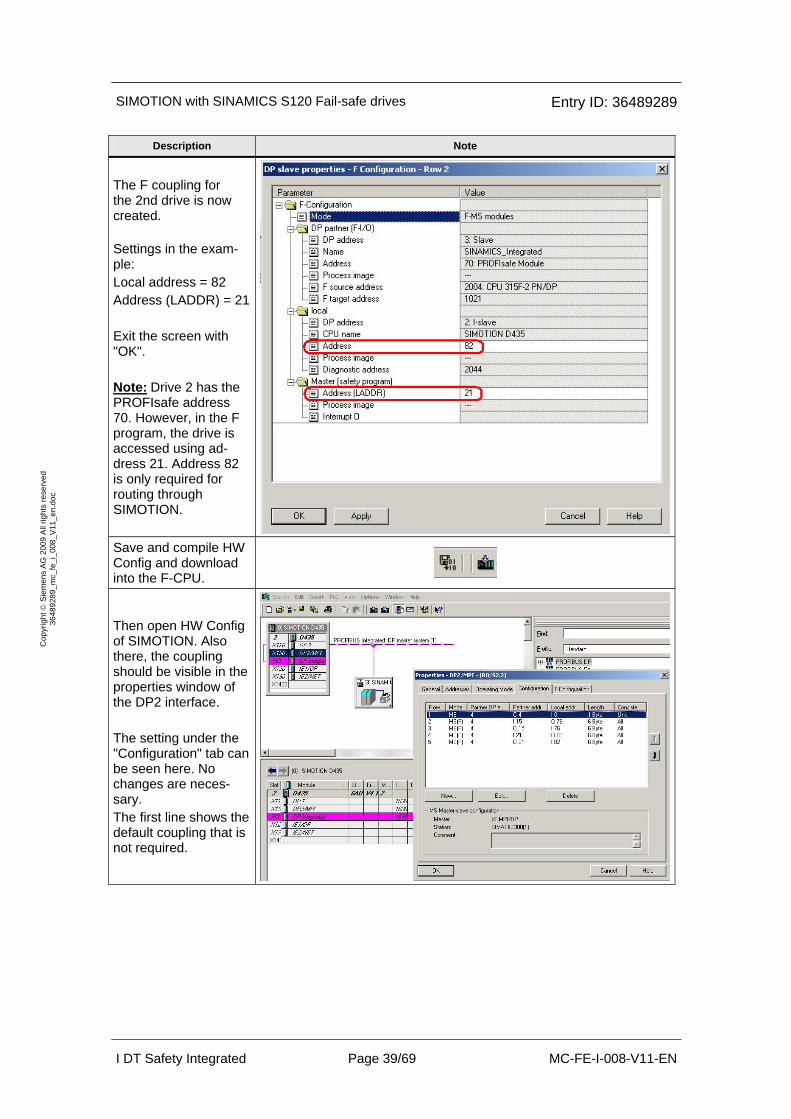
The F coupling for the 2nd drive is now created. Settings in the exam-ple: Local address = 82 Address (LADDR) = 21 Exit the screen with "OK". Note: Drive 2 has the PROFIsafe address 70. However, in the F program, the drive is accessed using ad-dress 21. Address 82 is only required for routing through SIMOTION.
Save and compile HW Config and download into the F-CPU.
Then open HW Config of SIMOTION. Also there, the coupling should be visible in the properties window of the DP2 interface. The setting under the "Configuration" tab can be seen here. No changes are neces-sary. The first line shows the default coupling that is not required.

SIMOTION with SINAMICS S120 Fail-safe drives Entry ID: 36489289
I DT Safety Integrated Page 40/69 MC-FE-I-008-V11-EN
Cop
yrig
ht ©
Sie
men
s A
G 2
009
All
right
s re
serv
ed
3648
9289
_mc_
fe_i
_008
_V11
_en.
doc
Description Note
The settings under the "F configuration" tab can be seen here. Also here, changes are not required.
To check that the PROFIsafe setting of the drives has been correctly configured, the "DP slave proper-ties" screen form of SINAMICS Integrated is first opened. The "Activate" button should be pressed in the "Configuration" tab. Object 1 is Servo_02 (red Drive) and Object 2 is Servo_03 (blue Drive)
Select the object and then press the “PROFIsafe” button will take you to the screens shown next.

SIMOTION with SINAMICS S120 Fail-safe drives Entry ID: 36489289
I DT Safety Integrated Page 41/69 MC-FE-I-008-V11-EN
Cop
yrig
ht ©
Sie
men
s A
G 2
009
All
right
s re
serv
ed
3648
9289
_mc_
fe_i
_008
_V11
_en.
doc
Description Note
The PROFIsafe set-tings of the 1st drive are shown in this screen form. No chan-ges are necessary. "F_Dest_Add" desig-nates the PROFIsafe address of the 1st drive. This is required later when configuring the Safety functions of the drives. The value is 3FE hex (= 1022 dec). Note: The watchdog time (F_WD_Time) must be higher then the OB35 cycle. Therefore, in this ex-ample, we have OB35 at 100msec and F_WD_Time = 150msec. The PROFIsafe set-tings of the 2nd drive are shown in this screen form. No chan-ges are necessary. "F_Dest_Add" desig-nates the PROFIsafe address of the 2nd drive. This is required later when configuring the Safety functions of the drives. The value is 3FD hex (= 1021 dec). Note: The watchdog time (F_WD_Time) must be higher then the OB35 cycle. Therefore, in this ex-ample, we have OB35 at 100msec and F_WD_Time = 150msec. HW Config of SIMOTION must now be saved, compiled and downloaded.

SIMOTION with SINAMICS S120 Fail-safe drives Entry ID: 36489289
I DT Safety Integrated Page 42/69 MC-FE-I-008-V11-EN
Cop
yrig
ht ©
Sie
men
s A
G 2
009
All
right
s re
serv
ed
3648
9289
_mc_
fe_i
_008
_V11
_en.
doc
6.3 Programming the fail-safe control
The safety program was deliberately selected to be as simple as possible. In this particular case, the main task of the safety program is to generate the PROFIsafe control words for the drives from the signals at the F-DIs. These are transferred to the drives using the PROFIsafe message frame (telegram) where it controls the safety functions. The blocks required for the safety program are first created.
Caution: In this form, it is not permissible that the program is used for a real applica-tion.
You start with the F-call block. This is required to call the safety program. To do this, a function (in this case, FC1) must be inserted into the block fol-der using the F-call programming language. Cyclic interrupt OB35 is re-quired to cyclically call the safety program.
In this example, the actual safety program is executed in a function block (here, FB1), this means that FB 1 must now be inserted using the F-LAD or F-FBD programming language.
Description Note
Programming OB35 Calling the safety pro-gram

SIMOTION with SINAMICS S120 Fail-safe drives Entry ID: 36489289
I DT Safety Integrated Page 43/69 MC-FE-I-008-V11-EN
Cop
yrig
ht ©
Sie
men
s A
G 2
009
All
right
s re
serv
ed
3648
9289
_mc_
fe_i
_008
_V11
_en.
doc
Description Note
Programming FB1 Network 1: Activate automatic acknowledgement Network 2: -S4 is used for ac-knowledgement (for faults that cannot be automatically acknowl-edged) PROFIsafe STW for drive 1; A15 and A16 (LOW/HIGH byte) Network 3: -S1 is interconnected to A15.0 (STO). Network 4: A15.1 (SS1) is perma-nently deselected with VKE1.

SIMOTION with SINAMICS S120 Fail-safe drives Entry ID: 36489289
I DT Safety Integrated Page 44/69 MC-FE-I-008-V11-EN
Cop
yrig
ht ©
Sie
men
s A
G 2
009
All
right
s re
serv
ed
3648
9289
_mc_
fe_i
_008
_V11
_en.
doc
Description Note
Programming FB1 PROFIsafe STW for drive 1; A15 and A16 (LOW/HIGH byte) Network 5: A15.2 (SS2) is perma-nently deselected with VKE1. Network 6: -S2 is interconnected to A15.3 (SOS). Inver-sion is necessary, as -S2 is connected as NO/NC contact. Network 7: A15.4 (SLS) is perma-nently deselected with VKE1. Network 8: -S4 is interconnected to A15.7 (fail-safe ac-knowledgement). Networks 9 and 10: VKE0 is intercon-nected to A16.1 and A16.2, therefore SLS stage 1 is permanently selected.
SIMOTION with SINAMICS S120 Fail-safe drives Entry ID: 36489289
I DT Safety Integrated Page 45/69 MC-FE-I-008-V11-EN
Cop
yrig
ht ©
Sie
men
s A
G 2
009
All
right
s re
serv
ed
3648
9289
_mc_
fe_i
_008
_V11
_en.
doc
Description Note
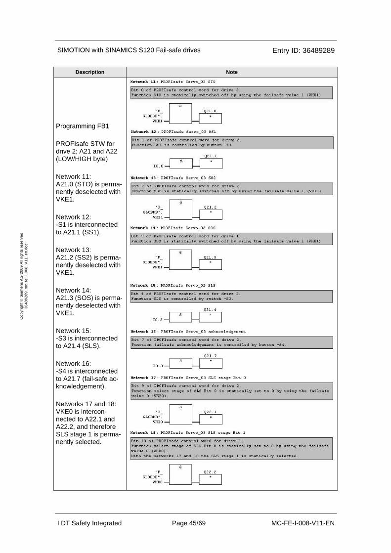
Programming FB1 PROFIsafe STW for drive 2; A21 and A22 (LOW/HIGH byte) Network 11: A21.0 (STO) is perma-nently deselected with VKE1. Network 12: -S1 is interconnected to A21.1 (SS1). Network 13: A21.2 (SS2) is perma-nently deselected with VKE1. Network 14: A21.3 (SOS) is perma-nently deselected with VKE1. Network 15: -S3 is interconnected to A21.4 (SLS). Network 16: -S4 is interconnected to A21.7 (fail-safe ac-knowledgement). Networks 17 and 18: VKE0 is intercon-nected to A22.1 and A22.2, and therefore SLS stage 1 is perma-nently selected.
SIMOTION with SINAMICS S120 Fail-safe drives Entry ID: 36489289
I DT Safety Integrated Page 46/69 MC-FE-I-008-V11-EN
Cop
yrig
ht ©
Sie
men
s A
G 2
009
All
right
s re
serv
ed
3648
9289
_mc_
fe_i
_008
_V11
_en.
doc
Description Note
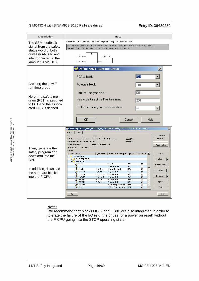
The SSM feedback signal from the safety status word of both drives is AND'ed and interconnected to the lamp in S4 via DO7.
Creating the new F-run-time group Here, the safety pro-gram (FB1) is assigned to FC1 and the associ-ated I-DB is defined.
Then, generate the safety program and download into the CPU. In addition, download the standard blocks into the F-CPU.
Note: We recommend that blocks OB82 and OB86 are also integrated in order to tolerate the failure of the I/O (e.g. the drives for a power on reset) without the F-CPU going into the STOP operating state.
SIMOTION with SINAMICS S120 Fail-safe drives Entry ID: 36489289
I DT Safety Integrated Page 47/69 MC-FE-I-008-V11-EN
Cop
yrig
ht ©
Sie
men
s A
G 2
009
All
right
s re
serv
ed
3648
9289
_mc_
fe_i
_008
_V11
_en.
doc
6.4 Parameterizing the safety functions in SINAMICS Integrated
6.4.1 Configuring the safety functions in the drives
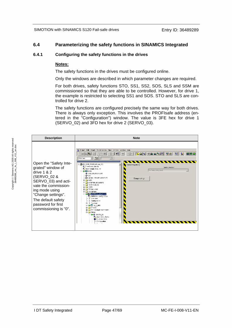
Notes: The safety functions in the drives must be configured online.
Only the windows are described in which parameter changes are required.
For both drives, safety functions STO, SS1, SS2, SOS, SLS and SSM are commissioned so that they are able to be controlled. However, for drive 1, the example is restricted to selecting SS1 and SOS. STO and SLS are con-trolled for drive 2.
The safety functions are configured precisely the same way for both drives. There is always only exception. This involves the PROFIsafe address (en-tered in the "Configuration") window. The value is 3FE hex for drive 1 (SERVO_02) and 3FD hex for drive 2 (SERVO_03).
Description Note
Open the "Safety Inte-grated" window of drive 1 & 2 (SERVO_02 & SERVO_03) and acti-vate the commission-ing mode using "Change settings". The default safety password for first commissioning is "0".
SIMOTION with SINAMICS S120 Fail-safe drives Entry ID: 36489289
I DT Safety Integrated Page 48/69 MC-FE-I-008-V11-EN
Cop
yrig
ht ©
Sie
men
s A
G 2
009
All
right
s re
serv
ed
3648
9289
_mc_
fe_i
_008
_V11
_en.
doc
Description Note
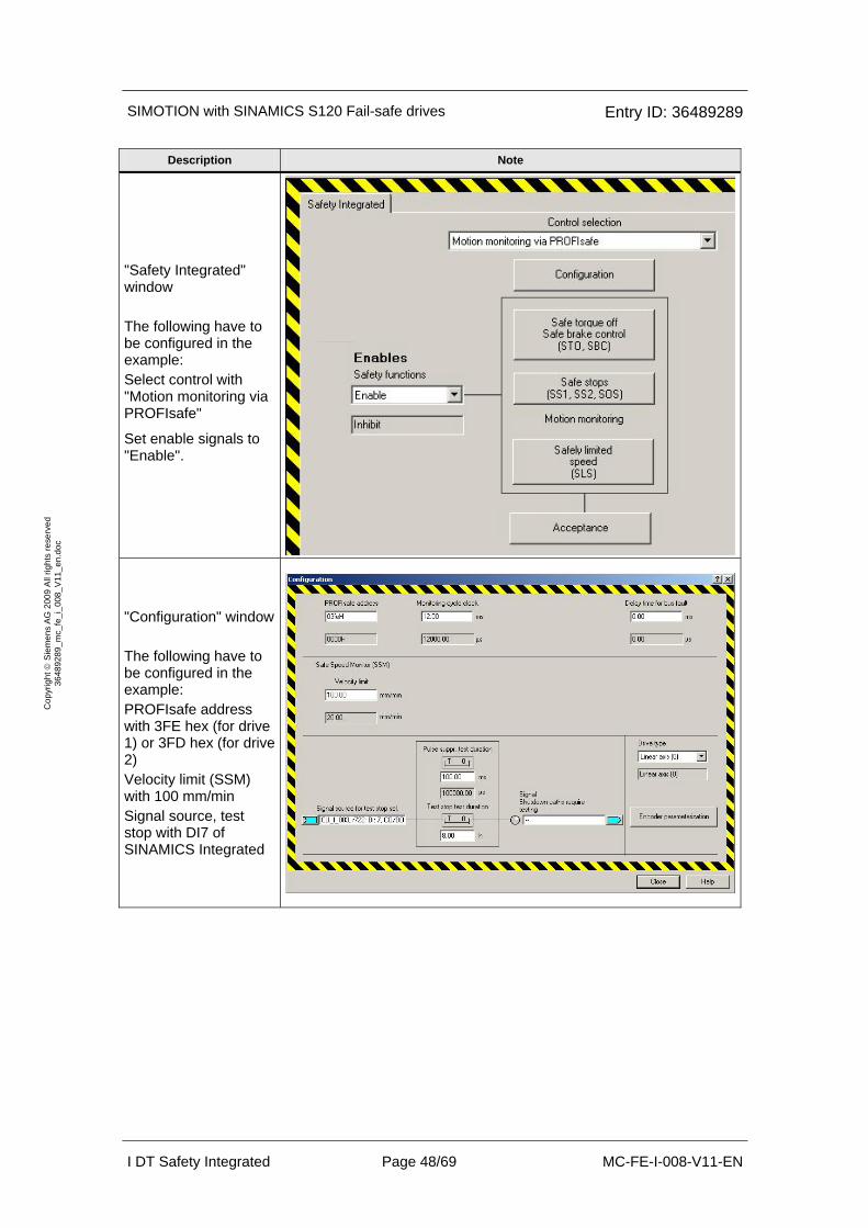
"Safety Integrated" window The following have to be configured in the example: Select control with "Motion monitoring via PROFIsafe"
Set enable signals to "Enable".
"Configuration" window The following have to be configured in the example: PROFIsafe address with 3FE hex (for drive 1) or 3FD hex (for drive 2) Velocity limit (SSM) with 100 mm/min Signal source, test stop with DI7 of SINAMICS Integrated
SIMOTION with SINAMICS S120 Fail-safe drives Entry ID: 36489289
I DT Safety Integrated Page 49/69 MC-FE-I-008-V11-EN
Cop
yrig
ht ©
Sie
men
s A
G 2
009
All
right
s re
serv
ed
3648
9289
_mc_
fe_i
_008
_V11
_en.
doc
Description Note
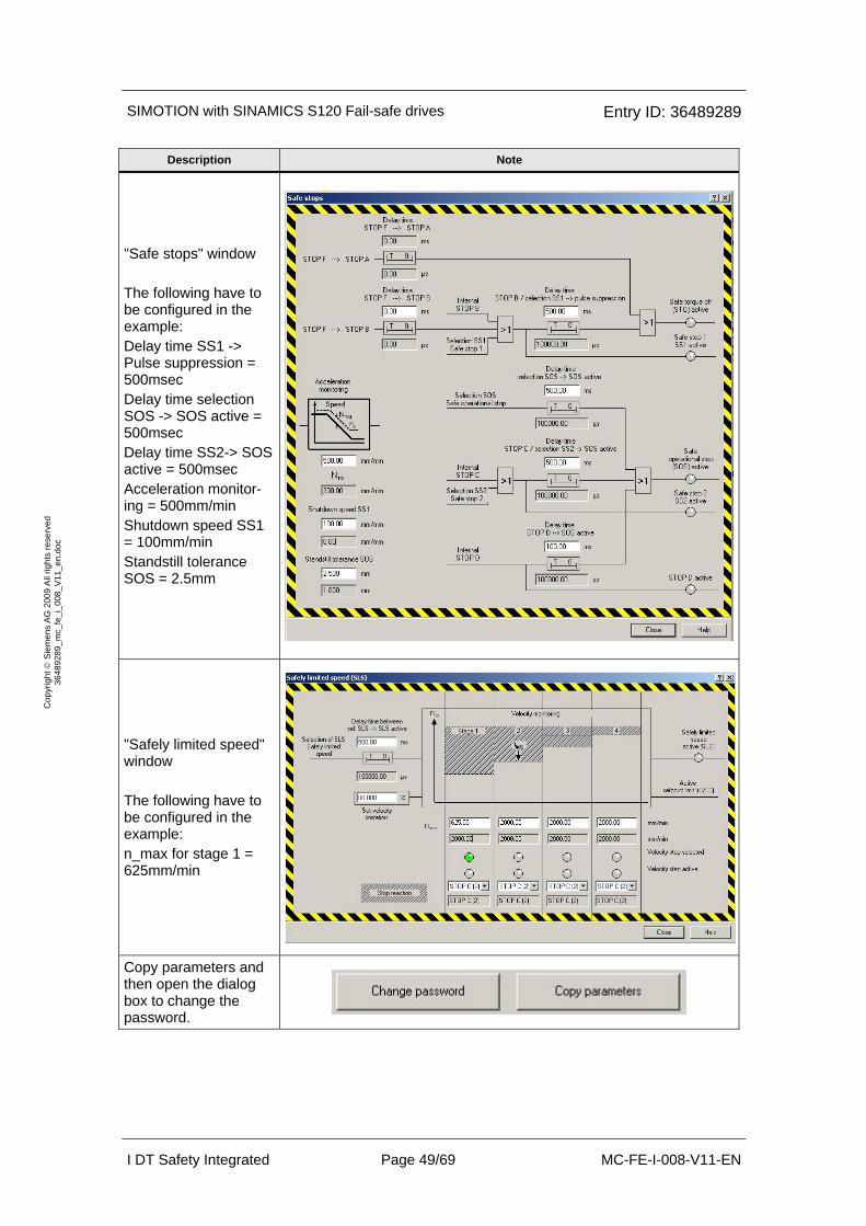
"Safe stops" window The following have to be configured in the example: Delay time SS1 -> Pulse suppression = 500msec Delay time selection SOS -> SOS active = 500msec Delay time SS2-> SOS active = 500msec Acceleration monitor-ing = 500mm/min Shutdown speed SS1 = 100mm/min Standstill tolerance SOS = 2.5mm
"Safely limited speed" window The following have to be configured in the example: n_max for stage 1 = 625mm/min
Copy parameters and then open the dialog box to change the password.
SIMOTION with SINAMICS S120 Fail-safe drives Entry ID: 36489289
I DT Safety Integrated Page 50/69 MC-FE-I-008-V11-EN
Cop
yrig
ht ©
Sie
men
s A
G 2
009
All
right
s re
serv
ed
3648
9289
_mc_
fe_i
_008
_V11
_en.
doc
Description Note
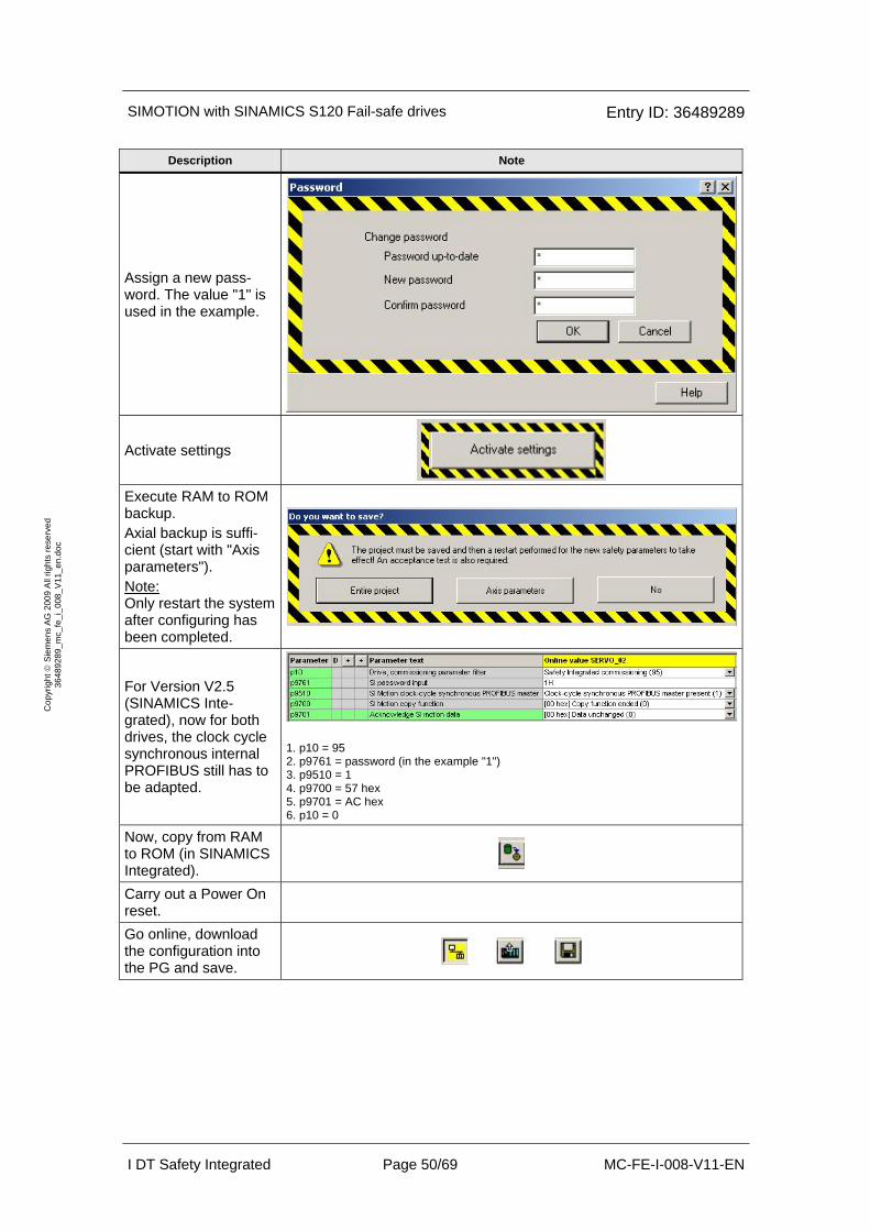
Assign a new pass-word. The value "1" is used in the example.
Activate settings
Execute RAM to ROM backup. Axial backup is suffi-cient (start with "Axis parameters"). Note: Only restart the system after configuring has been completed.
For Version V2.5 (SINAMICS Inte-grated), now for both drives, the clock cycle synchronous internal PROFIBUS still has to be adapted.
1. p10 = 95 2. p9761 = password (in the example "1") 3. p9510 = 1 4. p9700 = 57 hex 5. p9701 = AC hex 6. p10 = 0
Now, copy from RAM to ROM (in SINAMICS Integrated).
Carry out a Power On reset.
Go online, download the configuration into the PG and save.
SIMOTION with SINAMICS S120 Fail-safe drives Entry ID: 36489289
I DT Safety Integrated Page 51/69 MC-FE-I-008-V11-EN
Cop
yrig
ht ©
Sie
men
s A
G 2
009
All
right
s re
serv
ed
3648
9289
_mc_
fe_i
_008
_V11
_en.
doc
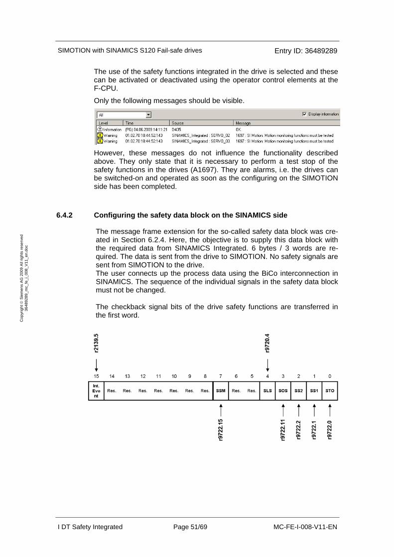
The use of the safety functions integrated in the drive is selected and these can be activated or deactivated using the operator control elements at the F-CPU.
Only the following messages should be visible.
However, these messages do not influence the functionality described above. They only state that it is necessary to perform a test stop of the safety functions in the drives (A1697). They are alarms, i.e. the drives can be switched-on and operated as soon as the configuring on the SIMOTION side has been completed.
6.4.2 Configuring the safety data block on the SINAMICS side
The message frame extension for the so-called safety data block was cre-ated in Section 6.2.4. Here, the objective is to supply this data block with the required data from SINAMICS Integrated. 6 bytes / 3 words are re-quired. The data is sent from the drive to SIMOTION. No safety signals are sent from SIMOTION to the drive. The user connects up the process data using the BiCo interconnection in SINAMICS. The sequence of the individual signals in the safety data block must not be changed. The checkback signal bits of the drive safety functions are transferred in the first word.

SIMOTION with SINAMICS S120 Fail-safe drives Entry ID: 36489289
I DT Safety Integrated Page 52/69 MC-FE-I-008-V11-EN
Cop
yrig
ht ©
Sie
men
s A
G 2
009
All
right
s re
serv
ed
3648
9289
_mc_
fe_i
_008
_V11
_en.
doc
The following BiCo interconnection must be made for each drive:
The status word is then available at parameter r2089[3].
The effective setpoint speed limiting when selecting SLS (r9733) is trans-ferred as floating-point number in the second and third words.
The interconnection of the safety datablock on the drive side has the follow-ing assignment:
The SINAMICS safety status signals are shown in the SIMOTION system variables D435.Axis_1.drivedata.drivesafetyextendedfunctionsinfodata.state.
The value of the setpoint speed limit is shown in D435.Axis_1.drivedata.drivesafetyextendedfunctionsinfodata.safespeedlimit.
Safety status word r2089[3]
effective setpoint speed limiting r9733 [0] = p9531 [x] * p9533 / p9520 (x: selected SLS stage)

SIMOTION with SINAMICS S120 Fail-safe drives Entry ID: 36489289
I DT Safety Integrated Page 53/69 MC-FE-I-008-V11-EN
Cop
yrig
ht ©
Sie
men
s A
G 2
009
All
right
s re
serv
ed
3648
9289
_mc_
fe_i
_008
_V11
_en.
doc
6.5 SIMOTION
6.5.1 Creating SIMOTION axes
On the SIMOTION side, the axes should be created using the Commission-ing Wizards. SERVO_02 (red) is assigned to Axis_1, SERVO_03 (blue) is correspondingly connected to Axis_2. The procedure is shown for an axis (Axis_1) as example. The two axes must be configured before the project is downloaded into SIMOTION.
Description Note
Start the Commission-ing Wizards by double-clicking on "Insert Axis" in the Project Naviga-tor. In the example, the first axis is called "Axis_1". "Speed control" and "Positioning" are acti-vated.
The default values are kept. It involves a lin-ear axis with electric drive.
SIMOTION with SINAMICS S120 Fail-safe drives Entry ID: 36489289
I DT Safety Integrated Page 54/69 MC-FE-I-008-V11-EN
Cop
yrig
ht ©
Sie
men
s A
G 2
009
All
right
s re
serv
ed
3648
9289
_mc_
fe_i
_008
_V11
_en.
doc
Description Note
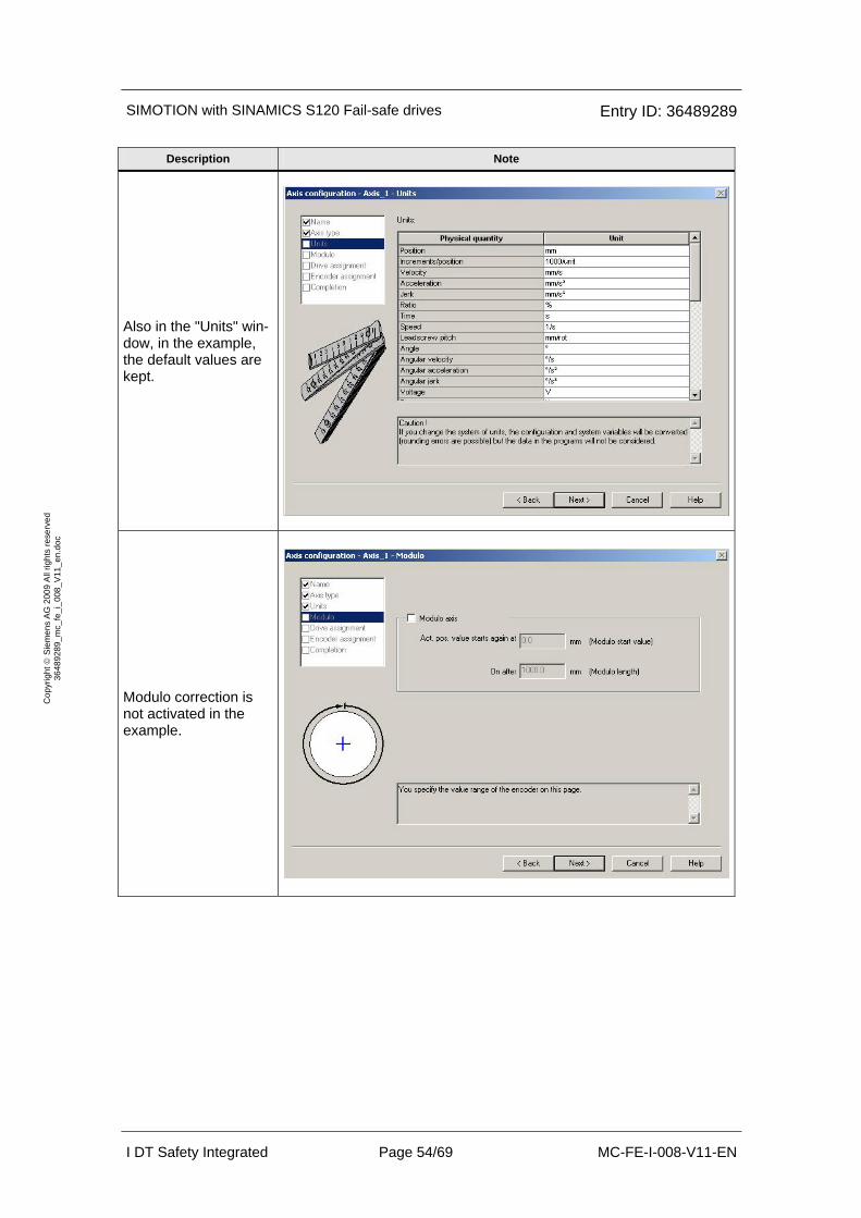
Also in the "Units" win-dow, in the example, the default values are kept.
Modulo correction is not activated in the example.
SIMOTION with SINAMICS S120 Fail-safe drives Entry ID: 36489289
I DT Safety Integrated Page 55/69 MC-FE-I-008-V11-EN
Cop
yrig
ht ©
Sie
men
s A
G 2
009
All
right
s re
serv
ed
3648
9289
_mc_
fe_i
_008
_V11
_en.
doc
Description Note
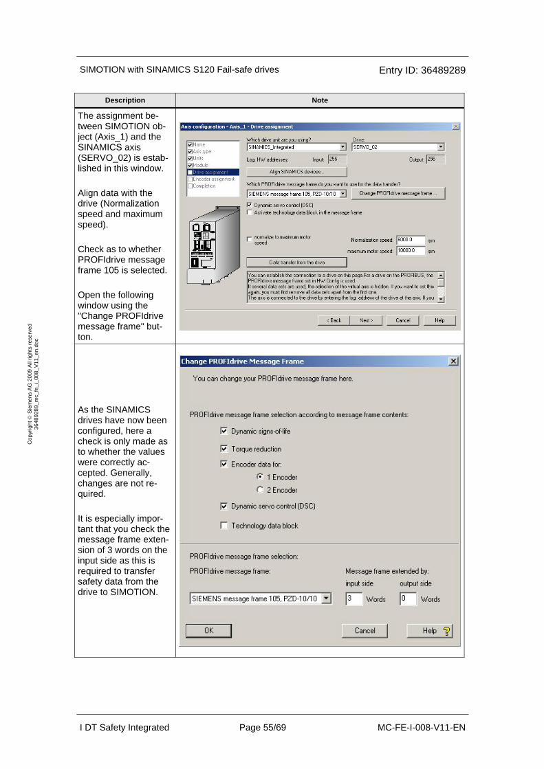
The assignment be-tween SIMOTION ob-ject (Axis_1) and the SINAMICS axis (SERVO_02) is estab-lished in this window. Align data with the drive (Normalization speed and maximum speed). Check as to whether PROFIdrive message frame 105 is selected. Open the following window using the "Change PROFIdrive message frame" but-ton.
As the SINAMICS drives have now been configured, here a check is only made as to whether the values were correctly ac-cepted. Generally, changes are not re-quired. It is especially impor-tant that you check the message frame exten-sion of 3 words on the input side as this is required to transfer safety data from the drive to SIMOTION.
SIMOTION with SINAMICS S120 Fail-safe drives Entry ID: 36489289
I DT Safety Integrated Page 56/69 MC-FE-I-008-V11-EN
Cop
yrig
ht ©
Sie
men
s A
G 2
009
All
right
s re
serv
ed
3648
9289
_mc_
fe_i
_008
_V11
_en.
doc
Description Note
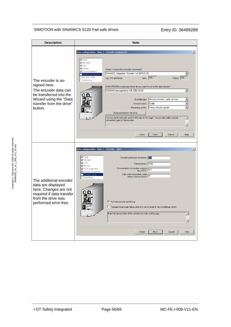
The encoder is as-signed here. The encoder data can be transferred into the Wizard using the "Data transfer from the drive" button.
The additional encoder data are displayed here. Changes are not required if data transfer from the drive was performed error-free.

SIMOTION with SINAMICS S120 Fail-safe drives Entry ID: 36489289
I DT Safety Integrated Page 57/69 MC-FE-I-008-V11-EN
Cop
yrig
ht ©
Sie
men
s A
G 2
009
All
right
s re
serv
ed
3648
9289
_mc_
fe_i
_008
_V11
_en.
doc
Description Note
Complete the Wizard to create the axis ob-ject on SIMOTION.
After completing the Commissioning Wiz-ards, for the example, only a few parameter changes are required. These are shown in the following windows. "Default value" window Set the velocity to a value of 83.33 mm/s (this corresponds to 500 rpm). The value of 333.33mm/s2 is en-tered for the accelera-tion and deceleration.
SIMOTION with SINAMICS S120 Fail-safe drives Entry ID: 36489289
I DT Safety Integrated Page 58/69 MC-FE-I-008-V11-EN
Cop
yrig
ht ©
Sie
men
s A
G 2
009
All
right
s re
serv
ed
3648
9289
_mc_
fe_i
_008
_V11
_en.
doc
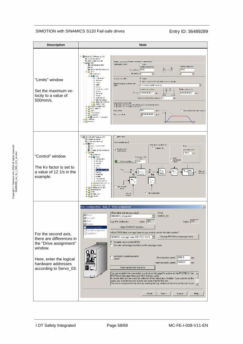
Description Note
"Limits" window Set the maximum ve-locity to a value of 500mm/s.
"Control" window The Kv factor is set to a value of 12 1/s in the example.
For the second axis, there are differences in the "Drive assignment" window. Here, enter the logical hardware addresses according to Servo_03.

SIMOTION with SINAMICS S120 Fail-safe drives Entry ID: 36489289
I DT Safety Integrated Page 59/69 MC-FE-I-008-V11-EN
Cop
yrig
ht ©
Sie
men
s A
G 2
009
All
right
s re
serv
ed
3648
9289
_mc_
fe_i
_008
_V11
_en.
doc
Description Note
For the second axis, there are also differ-ences in the "Encoder assignment" window. The encoder data can be transferred into the Wizard using the "Data transfer from the drive" button.
For the second axis, there are also differ-ences in the "Encoder data" window. The additional encoder data are displayed here. Changes are not required if data transfer from the drive was performed error-free.

SIMOTION with SINAMICS S120 Fail-safe drives Entry ID: 36489289
I DT Safety Integrated Page 60/69 MC-FE-I-008-V11-EN
Cop
yrig
ht ©
Sie
men
s A
G 2
009
All
right
s re
serv
ed
3648
9289
_mc_
fe_i
_008
_V11
_en.
doc
Description Note
As the "Safety alarms" of SIMOTION do not completely comply with the specification, it is recommended that these are hidden for both axes. The window is opened by selecting the Tech-Fault task in the execu-tion system and then pressing the "Alarm configuration" button. In this example, the axis-specific responses are also not based on these alarms. Note: From Version 4.1 SP4 onwards the alarms are working correct. But it is still recommended not to use this alarms for the programming of the axis-specific re-sponses.
After the two axes have been commis-sioned on the SIMOTION side, the project must be saved and downloaded into SIMOTION (in the Project Navigator, se-lect D435).
If commissioning was carried out as shown here, then all of the settings for the safety block are correct. Now, it only has to be checked that the start address was correctly entered (276 for Axis_1 and 302 for Axis_2)
Axis_1
Axis_2

SIMOTION with SINAMICS S120 Fail-safe drives Entry ID: 36489289
I DT Safety Integrated Page 61/69 MC-FE-I-008-V11-EN
Cop
yrig
ht ©
Sie
men
s A
G 2
009
All
right
s re
serv
ed
3648
9289
_mc_
fe_i
_008
_V11
_en.
doc
6.5.2 SIMOTION programs
The programs used in the function example are briefly presented in this section. The program code and a very detailed description will not be given as the program itself has comments.
ST programs include the comments directly in the code. For MMC pro-grams, commented blocks are identified by a green triangle in the upper righthand corner. The comment can be opened by selecting the block and opening a menu with the righthand mouse key. Here, the "Enter comment ..." entry must be selected.
6.5.2.1 IO_ReadWrite (reading in or writing digital I/Os)
The digital inputs of SINAMICS Integrated of the SIMOTION D435 are used to control (open-loop) axis motion. These inputs are read into SIMOTION via the I/O variable "io_cu320_inword". The outputs of SINAMICS inte-grated can be controlled via the "io_cu320_outword" variable; however, this is not applicable for this example. The inputs are used, e.g. to switch-on the drives, start travel programs, acknowledge faults and to start the test stop or the forced dormant detection.
The two variables are created as shown as follows in the Project Navigator under "I/O".
In this example, SINAMICS Integrated provides the DIs at address 310 (corresponds to PZD 2 of the Control Unit in the send direction). Address 298 should also be used for the outputs (corresponds to PZD 2 of the Con-trol Unit, receive direction).
The "IO_ReadWrite" program was taken from the FAQ with number 29063656. The program parts not required were subsequently removed. Detailed documentation as well as the program code can be downloaded under the following link: http://support.automation.siemens.com/WW/view/en/29063656
The program is executed in the background task and provides the signals for the program sequence of SIMOTION at the digital inputs of SINAMICS Integrated via the variables mentioned above.
6.5.2.2 Axis_01.mmc_bg_task1 (sequential control system for Axis_1)
The upper drive of the demonstration case (Axis_1; or SERVO_02) is con-trolled using this program. The program is cyclically processed in the back-ground task and is responsible for switching-in/switching-out the axis en-able signals, the fault acknowledgement as well as starting and stopping the travel program "mt_axis_1".
Program functions: -S5 (DI 0) setting or withdrawing enable signals for Axis_1

SIMOTION with SINAMICS S120 Fail-safe drives Entry ID: 36489289
I DT Safety Integrated Page 62/69 MC-FE-I-008-V11-EN
Cop
yrig
ht ©
Sie
men
s A
G 2
009
All
right
s re
serv
ed
3648
9289
_mc_
fe_i
_008
_V11
_en.
doc
-S6 (DI 1) starting or stopping the travel program "mt_axis_1". -S9 (DI 6) acknowledging alarms
6.5.2.3 Axis_02.mmc_bg_task2 (sequential control system for Axis_2)
The lower drive of the demonstration case (Axis_2; or SERVO_03) is con-trolled using this program. The program is cyclically processed in the back-ground task and is responsible for switching-in/switching-out the axis en-able signals, the fault acknowledgement as well as starting and stopping the travel program "mt_axis_2".
Program functions: -S7 (DI 2) setting or withdrawing enable signals for Axis_2 -S8 (DI 3) starting or stopping the travel program "mt_axis_2". -S9 (DI 6) acknowledging alarms
6.5.2.4 Axis_01.mt_axis_1 (travel program for Axis_1)
The travel program comprises 3 travel commands, which are cyclically called from "mmc_bg_task1", as long as a HIGH signal level is present at -S1. This means that after starting the travel program once, "endless mo-tion" of the axis is executed until this is interrupted by selecting a safety function or using a LOW signal level at -S1. This program is executed in MotionTask_3. This task is cyclically started from program "Axis_01.mmc_gb_task1".
6.5.2.5 Axis_02.mt_axis_2 (travel program for Axis_2)
The travel program comprises 3 travel commands, which are cyclically called from "mmc_bg_task2", as long as a HIGH signal level is present at -S3. This means that after starting the travel program once, "endless mo-tion" of the axis is executed until this is interrupted by selecting a safety function or using a LOW signal level at -S3. This program is executed in MotionTask_4. This task is cyclically started from program "Axis_02.mmc_gb_task2".
6.5.2.6 Axis_01.mt_safety_axis_1
The axis-specific responses to selecting or deselecting the safety functions are executed in this program. As several safety functions can be simulta-neously active, the priority must first be determined before the axis-specific response can be executed. To do this, the value of a variable is deter-mined, which can then be used to select the response (using a CASE statement). In the example, the subsequently described responses are ini-tiated for the individual functions. After they have been executed, the vari-ables for the state of the individual safety functions (determined in ST_Main.extsafety) as well as also for the priority assignment (determined in Axis_01.mt_safety_1) are reset. This program is executed in Motion-Task_6.
SIMOTION with SINAMICS S120 Fail-safe drives Entry ID: 36489289
I DT Safety Integrated Page 63/69 MC-FE-I-008-V11-EN
Cop
yrig
ht ©
Sie
men
s A
G 2
009
All
right
s re
serv
ed
3648
9289
_mc_
fe_i
_008
_V11
_en.
doc
STO When selecting STO, no special response is necessary as the impulses are immediately suppressed. When deselecting, a response is also not neces-sary as after deselecting STO, a new ON command must be set.
SS1 When selecting SS1, the axis must be switched into the follow-up mode and the "Axis_01.mt_axis_1" motion program interrupted. To do this, Mo-tionTask_3 and the actual traversing command are interrupted. When de-selecting SS1, MotionTask_3 is reset so that it can be restarted. As SS1 automatically results in an STO, a new ON command is required to restart axis motion.
SS2 When selecting SS2, the axis must be switched into the follow-up mode and the "Axis_01.mt_axis_1" motion program interrupted. To do this, Mo-tionTask_3 and the actual traversing command are interrupted. Motion-Task_3 is continued when SS2 is deselected. The motion is automatically continued when deselected. An additional command is not necessary.
SOS When selecting SOS, axis motion is stopped down to standstill in the closed-loop position controlled mode using a STOP command. Motion-Task_3 is then interrupted in order to prevent axis travel initiated by the next positioning command. When SOS is deselected, MotionTask_3 is con-tinued again and the next pending positioning command executed. This means that also here, a command is not necessary to restart axis motion.
SLS When selecting SLS, the maximum permissible velocity (SIMOTION vari-able: pluslimitsofdynamics.velocity) when positioning is reduced to the value that is transferred from SINAMICS Integrated (via the so-called safety data block) to SIMOTION. Motion is now executed at a reduced velocity. When deselecting SLS, this limit value is reset to the original value.
6.5.2.7 Axis_02.mt_safety_axis_2
See 6.6.2.6, whereby this program is processed in MotionTask_7 and axis motion of Axis_2 is monitored using MotionTask_4.
6.5.2.8 ST_VarGlobal
Variables required to evaluate the safety status word are defined in this ST program.
6.5.2.9 ST_Main
This program comprises the three subprograms "startup", "extsafety" and "techfault".
Note: From Version 4.1 SP4 onwards the SIMOTION safety messages 50201 to 50203 are working correct. In earlier versions the messages do not com-pletely comply with the specification. But we always recommend to evalu-

SIMOTION with SINAMICS S120 Fail-safe drives Entry ID: 36489289
I DT Safety Integrated Page 64/69 MC-FE-I-008-V11-EN
Cop
yrig
ht ©
Sie
men
s A
G 2
009
All
right
s re
serv
ed
3648
9289
_mc_
fe_i
_008
_V11
_en.
doc
ate the safety status cyclically and not to use the alarms for the axis-specific response.
"startup" In this program, the axis instances are assigned, i.e. it is defined as to which axis corresponds to which variable. Further, the velocity limit of the SIMOTION configuration project is buffered here in a variable. When se-lecting SLS, this value is overwritten and when deselected, must be avail-able again. The program is processed in the StartupTask.
"extsafety" The safety status work is evaluated in this program in order to obtain infor-mation as to which safety functions are in which state. A distinction is made between the states "selected" (coming event), "active" "deselected" (going event) and "inactive". Depending on this information, the motion task is then started, which includes the program for the axis-specific response to safety functions (MotionTask_6 for Axis_1 and MotionTask_7 for Axis_2).
In the example, the program is processed in the IPO task; however, this is only necessary if the SS2 or SS1 functions are being used. Without these two functions, processing in the Background Task is sufficient. When se-lecting safety functions SS1 or SS2, the drive immediately decouples itself from the higher-level setpoint of SIMOTION when the function is selected. It is now important to prevent a following error from occurring that would then result in pulse cancellation (for the standard setting). This is the reason that in these cases, processing must be as fast as possible. The SOS and SLS functions have a configurable timer between selecting and activating; this is the reason that there is more time available for the SIMOTION response.
"Techfault" This involves a dummy program that must be integrated in the Technologi-calFaultTask. If this is missing, then for a TechnologicalFault alarm, the op-erating state of SIMOTION changes into the "STOP" operating state.
6.5.2.10 other_MMCs.peripheralfault
This involves a dummy program that must be integrated in the Peripheral-FaultTask. If this is missing, then for a Peripheral-Fault alarm, the operating state of the SIMOTION changes into the "STOP" operating state.
6.5.2.11 other_MMCs.executionfault
This involves a dummy program that must be integrated in the Execution-FaultTask . If this is missing, then for a Execution-Fault alarm, the operating state of the SIMOTION changes into the "STOP" operating state.
6.5.3 Configuration of the execution system
The various SIMOTION programs must now be assigned to various tasks. The function example is based on the following configuration.

SIMOTION with SINAMICS S120 Fail-safe drives Entry ID: 36489289
I DT Safety Integrated Page 65/69 MC-FE-I-008-V11-EN
Cop
yrig
ht ©
Sie
men
s A
G 2
009
All
right
s re
serv
ed
3648
9289
_mc_
fe_i
_008
_V11
_en.
doc
SIMOTION with SINAMICS S120 Fail-safe drives Entry ID: 36489289
I DT Safety Integrated Page 66/69 MC-FE-I-008-V11-EN
Cop
yrig
ht ©
Sie
men
s A
G 2
009
All
right
s re
serv
ed
3648
9289
_mc_
fe_i
_008
_V11
_en.
doc
6.5.4 SIMOTION messages
6.5.4.1 Safety message
On the SIMOTION side, there are 3 messages for the extended safety functions.
50201: Safety alarm in the drive
50202: Drive starts Safety Integrated Extended function
50203: Drive completes Safety Integrated Extended function
Presently, these messages should still not be used for configuring the axis-specific responses of SIMOTION.
6.5.4.2 Other messages
When selecting the different safety functions, additional messages are dis-played. These are expected and do not represent incorrect behavior.
20005: Device type: X, log. address: Y faulted. This fault also occurs when selecting STO and SS1 and indicates that the drive has shut itself down.
30002: Command aborted (reason: X, Command type: Y) This message should also be monitored when selecting STO and SS1 as well as when "stopping" positioning by shutting down -S6 or S8. The reason for this message is that the actual positioning command was interrupted be-fore or during processing.
40002: Programmed velocity is limited The fault occurs when SLS is selected if the configured velocity lies above the limit for SLS.
40005: Missing enable signals(s) (Parameter1: X) and/or incorrect mode (Parameter2: Y) The fault occurs when STO is selected and means that for a pending mo-tion command, the axis enable signals are missing.
6.6 Download of the project example
Up until now, the configuration of the function example was described step-by-step. The following steps should now be followed if the project example is to be directly downloaded into the hardware.
To start, all of the components (S7-F-CPU, SIMOTION and SINAMICS In-tegrated) should be generally reset or reset to the factory setting.
6.6.1 Downloading the S7-F-CPU project configuration
To start, the HW configuration of the S7-F-CPU must be downloaded. The HW configuration is opened by double-clicking on "Hardware".
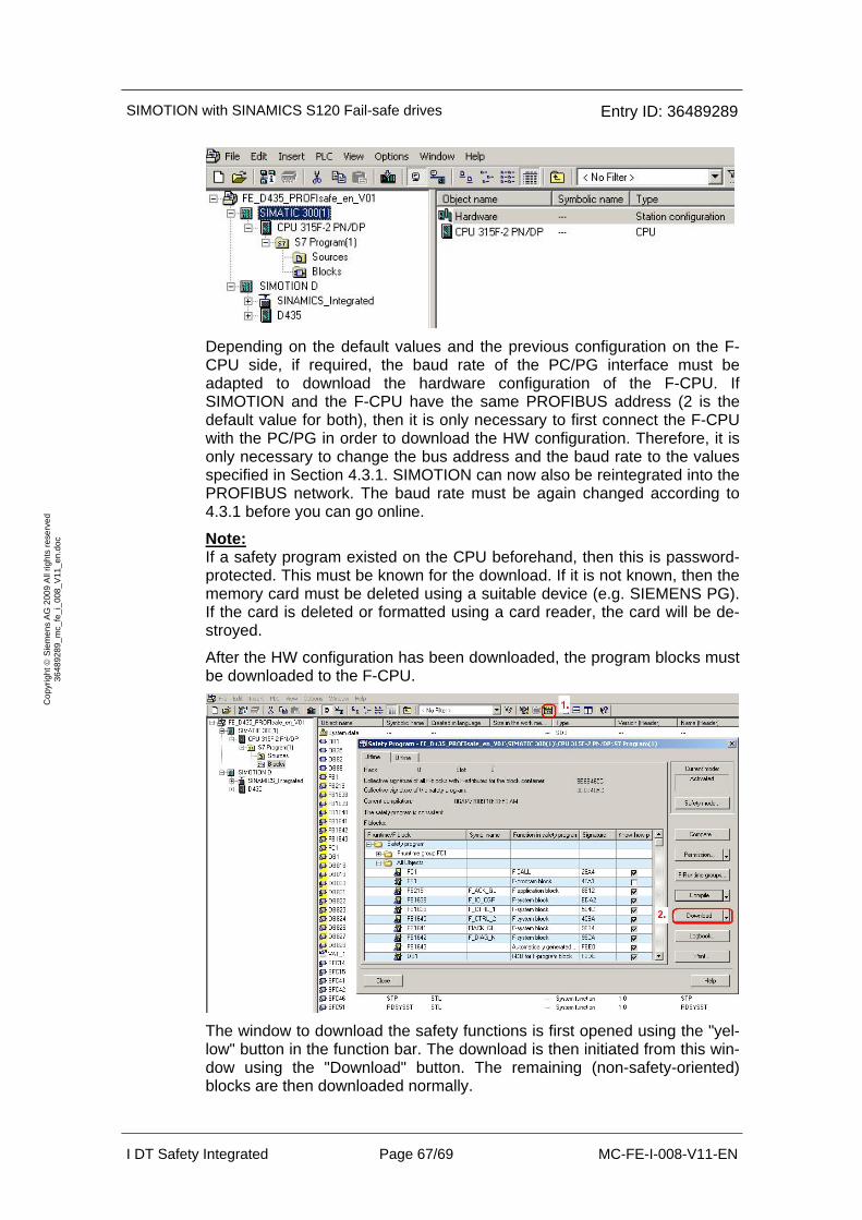
SIMOTION with SINAMICS S120 Fail-safe drives Entry ID: 36489289
I DT Safety Integrated Page 67/69 MC-FE-I-008-V11-EN
Cop
yrig
ht ©
Sie
men
s A
G 2
009
All
right
s re
serv
ed
3648
9289
_mc_
fe_i
_008
_V11
_en.
doc
Depending on the default values and the previous configuration on the F-CPU side, if required, the baud rate of the PC/PG interface must be adapted to download the hardware configuration of the F-CPU. If SIMOTION and the F-CPU have the same PROFIBUS address (2 is the default value for both), then it is only necessary to first connect the F-CPU with the PC/PG in order to download the HW configuration. Therefore, it is only necessary to change the bus address and the baud rate to the values specified in Section 4.3.1. SIMOTION can now also be reintegrated into the PROFIBUS network. The baud rate must be again changed according to 4.3.1 before you can go online.
Note: If a safety program existed on the CPU beforehand, then this is password-protected. This must be known for the download. If it is not known, then the memory card must be deleted using a suitable device (e.g. SIEMENS PG). If the card is deleted or formatted using a card reader, the card will be de-stroyed.
After the HW configuration has been downloaded, the program blocks must be downloaded to the F-CPU.
The window to download the safety functions is first opened using the "yel-low" button in the function bar. The download is then initiated from this win-dow using the "Download" button. The remaining (non-safety-oriented) blocks are then downloaded normally.
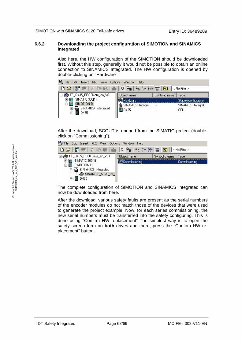
SIMOTION with SINAMICS S120 Fail-safe drives Entry ID: 36489289
I DT Safety Integrated Page 68/69 MC-FE-I-008-V11-EN
Cop
yrig
ht ©
Sie
men
s A
G 2
009
All
right
s re
serv
ed
3648
9289
_mc_
fe_i
_008
_V11
_en.
doc
6.6.2 Downloading the project configuration of SIMOTION and SINAMICS Integrated
Also here, the HW configuration of the SIMOTION should be downloaded first. Without this step, generally it would not be possible to obtain an online connection to SINAMICS Integrated. The HW configuration is opened by double-clicking on "Hardware".
After the download, SCOUT is opened from the SIMATIC project (double-click on "Commissioning").
The complete configuration of SIMOTION and SINAMICS Integrated can now be downloaded from here.
After the download, various safety faults are present as the serial numbers of the encoder modules do not match those of the devices that were used to generate the project example. Now, for each series commissioning, the new serial numbers must be transferred into the safety configuring. This is done using "Confirm HW replacement" The simplest way is to open the safety screen form on both drives and there, press the "Confirm HW re-placement" button.
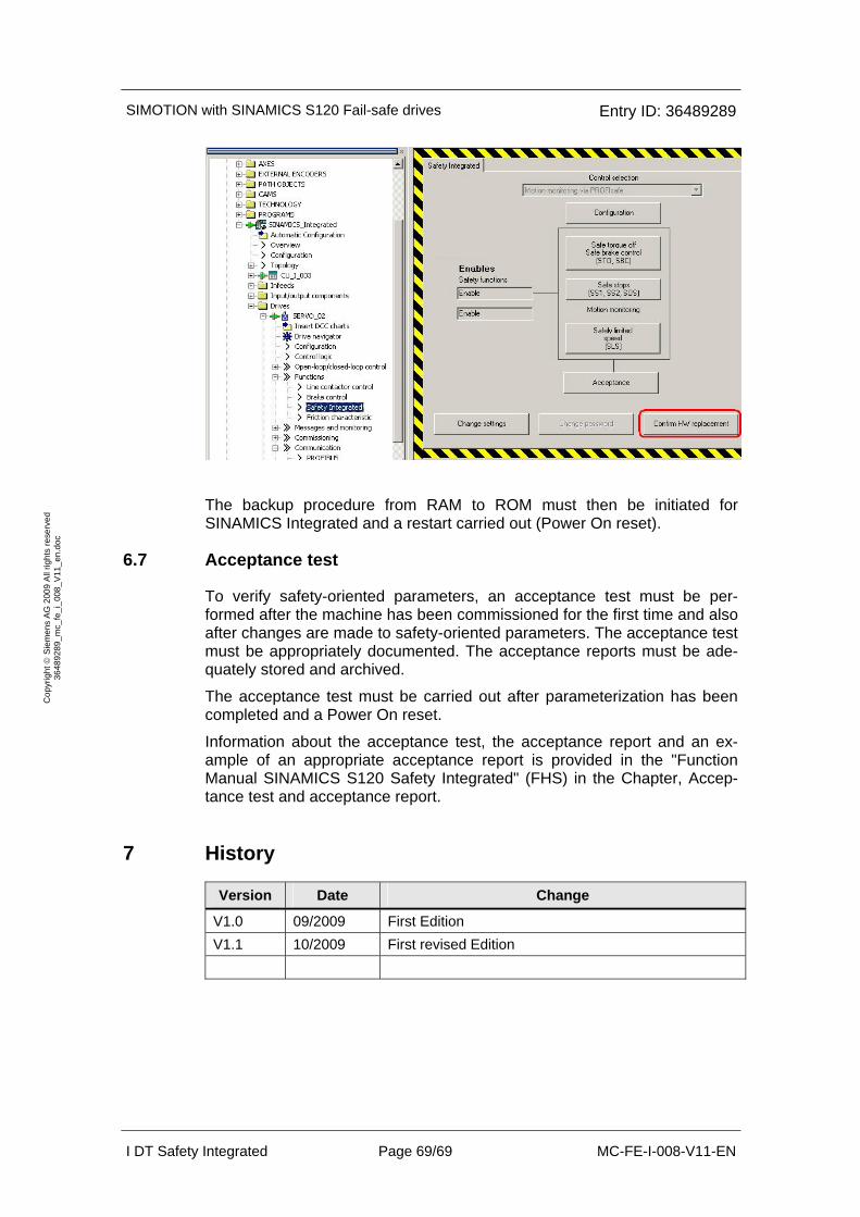
SIMOTION with SINAMICS S120 Fail-safe drives Entry ID: 36489289
I DT Safety Integrated Page 69/69 MC-FE-I-008-V11-EN
Cop
yrig
ht ©
Sie
men
s A
G 2
009
All
right
s re
serv
ed
3648
9289
_mc_
fe_i
_008
_V11
_en.
doc
The backup procedure from RAM to ROM must then be initiated for SINAMICS Integrated and a restart carried out (Power On reset).
6.7 Acceptance test
To verify safety-oriented parameters, an acceptance test must be per-formed after the machine has been commissioned for the first time and also after changes are made to safety-oriented parameters. The acceptance test must be appropriately documented. The acceptance reports must be ade-quately stored and archived.
The acceptance test must be carried out after parameterization has been completed and a Power On reset.
Information about the acceptance test, the acceptance report and an ex-ample of an appropriate acceptance report is provided in the "Function Manual SINAMICS S120 Safety Integrated" (FHS) in the Chapter, Accep-tance test and acceptance report.
7 History
Version Date Change
V1.0 09/2009 First Edition V1.1 10/2009 First revised Edition