SILT CURTAINS AS A DREDGING PROJECT … TN-DOER-E21 September 2005 . Silt Curtains as a Dredging...
18
ERDC TN-DOER-E21 September 2005 Silt Curtains as a Dredging Project Management Practice INTRODUCTION: Environmental windows are imposed on many U.S. Army Corps of Engineers (USACE) dredging projects in both coastal and inland watelWays. Over 83 protected or sensitive species that have been identified fall into at least 20 general categories of concern for potentially negative impacts from dredging and disposal operations. One of the most frequently cited reasons for establishing an environmental window is impacts from turbidity and suspended sediments (Reine, Dickerson, and Clarke 1998). Over the past 15 to 20 years there have also been increased concerns regarding the potential impacts that dredging of contaminated sediments may have on nearby environmental resources. In response to the need to protect sensitive environmental resources, silt or turbidity curtains have been designated a "best management practice (BMP)" by the Corps of Engineers, other Federal Agencies, and state regulatory authorities. Silt curtains are devices that control suspended solids and turbidity in the water column generated by dredging and disposal of dredged material. Consequently, silt curtains are considered an integral and necessary part of the regulatory strategy for many dredging projects. Unfortunately, factors contributing to the effectiveness of silt curtains under different circumstances are poorly understood by dredging project regulators and the public alike. Dredging contractors attest to the fact that, in their experience, silt curtains do not work under many of the site conditions encountered in navigation and environmental dredging projects. The published literature contains few comprehensive studies that demonstrate how effective silt curtains have been in meeting the intended project objectives (Johanson 1976, 1977; JBF Scientific Corporation 1978; Lawler, Matusky and Skelly Engineers 1983). One goal of the Dredging Operations and Environmental Research (DOER) Program is to provide current, accurate technical guidance on environmental controls for dredging operations. Remaining challenges include rigorous examination of silt or turbidity curtains as a temporary control measure to better define performance criteria and identification of technical guidelines for their selection and use in navigation and environmental dredging projects. PURPOSE: This technical note reviews the basic types of silt curtains used in navigation and environmental dredging projects. The emphasis is on the state of the practice and circumstances under which silt curtains function best. A checklist is provided to aid in consideration of silt curtain applications, including selection, design, specifications, deployment, and maintenance of silt curtains at dredging projects. This note also serves to update and supplement earlier guidance (e.g., Johanson 1977 and JBF Scientific Corporation (1978» published on the application and performance of silt curtains.
-
Upload
phungtuyen -
Category
Documents
-
view
213 -
download
0
Transcript of SILT CURTAINS AS A DREDGING PROJECT … TN-DOER-E21 September 2005 . Silt Curtains as a Dredging...
ERDC TN-DOER-E21 September 2005
Silt Curtains as a Dredging Project Management Practice
INTRODUCTION: Environmental windows are imposed on many U.S. Army Corps of Engineers (USACE) dredging projects in both coastal and inland watelWays. Over 83 protected or sensitive species that have been identified fall into at least 20 general categories of concern for potentially negative impacts from dredging and disposal operations. One of the most frequently cited reasons for establishing an environmental window is impacts from turbidity and suspended sediments (Reine, Dickerson, and Clarke 1998). Over the past 15 to 20 years there have also been increased concerns regarding the potential impacts that dredging of contaminated sediments may have on nearby environmental resources.
In response to the need to protect sensitive environmental resources, silt or turbidity curtains have been designated a "best management practice (BMP)" by the Corps of Engineers, other Federal Agencies, and state regulatory authorities. Silt curtains are devices that control suspended solids and turbidity in the water column generated by dredging and disposal of dredged material. Consequently, silt curtains are considered an integral and necessary part of the regulatory strategy for many dredging projects. Unfortunately, factors contributing to the effectiveness of silt curtains under different circumstances are poorly understood by dredging project regulators and the public alike. Dredging contractors attest to the fact that, in their experience, silt curtains do not work under many of the site conditions encountered in navigation and environmental dredging projects. The published literature contains few comprehensive studies that demonstrate how effective silt curtains have been in meeting the intended project objectives (Johanson 1976, 1977; JBF Scientific Corporation 1978; Lawler, Matusky and Skelly Engineers 1983).
One goal of the Dredging Operations and Environmental Research (DOER) Program is to provide current, accurate technical guidance on environmental controls for dredging operations. Remaining challenges include rigorous examination of silt or turbidity curtains as a temporary control measure to better define performance criteria and identification of technical guidelines for their selection and use in navigation and environmental dredging projects.
PURPOSE: This technical note reviews the basic types of silt curtains used in navigation and environmental dredging projects. The emphasis is on the state of the practice and circumstances under which silt curtains function best. A checklist is provided to aid in consideration of silt curtain applications, including selection, design, specifications, deployment, and maintenance of silt curtains at dredging projects. This note also serves to update and supplement earlier guidance (e.g., Johanson 1977 and JBF Scientific Corporation (1978» published on the application and performance of silt curtains.

ERDC TN-DOER-E21 September 2005
DEFINITIONS: Silt curtains, turbidity screens, silt/turbidity barriers, gunderbooms, etc., are not to be confused with silt fences used in terrestrial control of soil erosion. Silt curtains are designed specifically to control suspended solids and turbidity generated in the water column as a result of navigation and environmental dredging operations. Silt and turbidity control devices have many names that have been used interchangeably by the Corps of Engineers, the U.S. Environmental Protection Agency (USEPA), various State regulatory agencies, dredging contractors, consultants, and manufacturers and suppliers. The following terminology represents common usage:
• Silt is defined as fine-grained suspended material that can be readily resuspended or stripped from sediment that is either being hydraulically or mechanically dredged from or placed in the water. Resuspended matter is generally measured gravimetrically and expressed as Total Suspended Solids (TSS) in milligrams per liter.
• Turbidity is a measure of the optical properties (amount of scattering and absorption of light rays) of the water in which dredging and dredged material disposal occur. Turbidity is frequently expressed in Nephelometric Turbidity Units (NTU).
• A Silt/Turbidity Curtain has traditionally been defined as an impermeable device for control of suspended solids and turbidity in the water column generated by dredging and dredged material disposal operations. Recently, the term "silt curtain" has been used to describe floating vertical barriers fabricated from either solid or permeable materials.
• A Silt/Turbidity Screen is a flow-through filtering device for control of suspended material and turbidity in the water column generated by dredging and dredged material disposal operations. All screens are composites of solid material (usually to facilitate flotation and mooring purposes) and permeable geosynthetic fabrics to filter water and reduce water pressure on the device.
• A Gunderboom is a device similar to a silt or turbidity screen that has been modified to control oil spills by adding adsorbent geotextile material.
For the purposes of this technical note, the term "silt curtain" will be used generically to describe devices deployed in water to control suspended solids or turbidity resulting from dredging operations.
TYPICAL QUESTIONS ON SELECTION AND USE OF SILT CURTAINS
What Are the Components of Silt Curtains? Silt curtains are vertical, flexible structures that extend downward from the water surface to a specified water depth. Typically fabricated of flexible, polyester-reinforced thermoplastic (vinyl) fabric, the curtain is maintained in a vertical position by flotation material at the top and a ballast chain along the bottom (Figure 1).
A tension cable is often built into the curtain immediately above or just below the flotation segments (top tension) to absorb stresses imposed by currents and hydrodynamic turbulence. The curtains are usually manufactured in standard sections (e.g., up to 50 ft) that can be joined together at a particular site to provide a curtain of specified length. Curtains are generally deployed to extend to 1-2 ft above the bottom to allow mudflow to pass beneath them. Anchored
2

EROC TN-OOER-E21 September 2005
Tension . Cable
Extra Flotation to Compensate for Weight of End Connector
Handhold
A
__ I
Ie I Skirt
DepthII If
0 0 0 0~--I---~J A
End Connector
Buoyancy Float
Tension Cable
Skirt
Ballast Chain Grommet
pesign Waterline
Skirt Depth
View A-A
Figure 1. Construction of a typical silt curtain section (JBF Scientific Corporation (1978»
lines hold the curtain in a deployed configuration that can be U- or V -shaped, or circular or elliptical, depending upon the application.
What Are the Functions of Silt Curtains? Silt curtains are designed to contain or deflect suspended sediments or turbidity in the water column. Sediment containment within a limited
3
ERDC TN-DOER-E21 September 2005
area is intended to provide residence time to allow soil particles to settle out of suspension and reduce flow to other areas where negative impacts could occur. Suspended solids can also conceivably be diverted from areas where environmental damages could occur from the settlement of these suspended particles. Silt curtains may also be used to protect specific areas (e.g., sensitive habitats, water intakes, or recreational areas) from suspended sediment and particle-associated contamination.
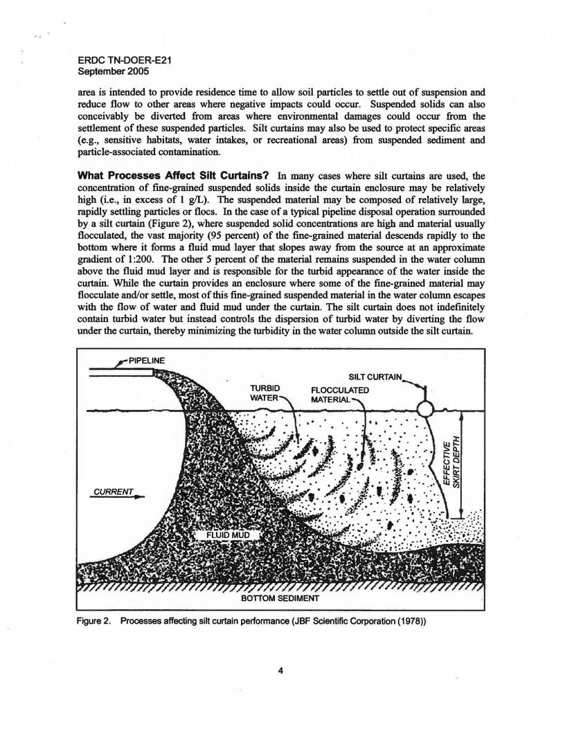
What Processes Affect Silt Curtains? In many cases where silt curtains are used, the concentration of fine-grained suspended solids inside the curtain enclosure may be relatively high (i.e., in excess of 1 gIL). The suspended material may be composed of relatively large, rapidly settling particles or flocs. In the case of a typical pipeline disposal operation surrounded by a silt curtain (Figure 2), where suspended solid concentrations are high and material usually flocculated, the vast majority (95 percent) of the fine-grained material descends rapidly to the bottom where it forms a fluid mud layer that slopes away from the source at an approximate gradient of 1 :200. The other 5 percent of the material remains suspended in the water column above the fluid mud layer and is responsible for the turbid appearance of the water inside the curtain. While the curtain provides an enclosure where some of the fine-grained material may flocculate and/or settle, most of this fine-grained suspended material in the water column escapes with the flow of water and fluid ~ud under the curtain. The silt curtain does not indefinitely contain turbid water but instead controls the dispersion of turbid water by diverting the flow under the curtain, thereby minimizing the turbidity in the water column outside the silt curtain.
CURRENT..
BonOM SEDIMENT
Figure 2. Processes affecting silt curtain performance (JBF Scientific Corporation (1978))
4
ERDC TN-DOER-E21 September 2005
Whereas properly deployed and maintained silt curtains can effectively control the distribution of turbid water, they are not designed to contain or control fluid mud. In fact, when the accumulation of fluid mud reaches the depth of the ballast chain along the lower edge of the skirt, the curtain must be moved away from the discharge; otherwise sediment accumulation on the lower edge of the skirt can pull the curtain underwater and eventually bury it. Consequently, the rate of fluid mud accumulation relative to changes in water depth due to tides must be considered during a silt curtain operation.
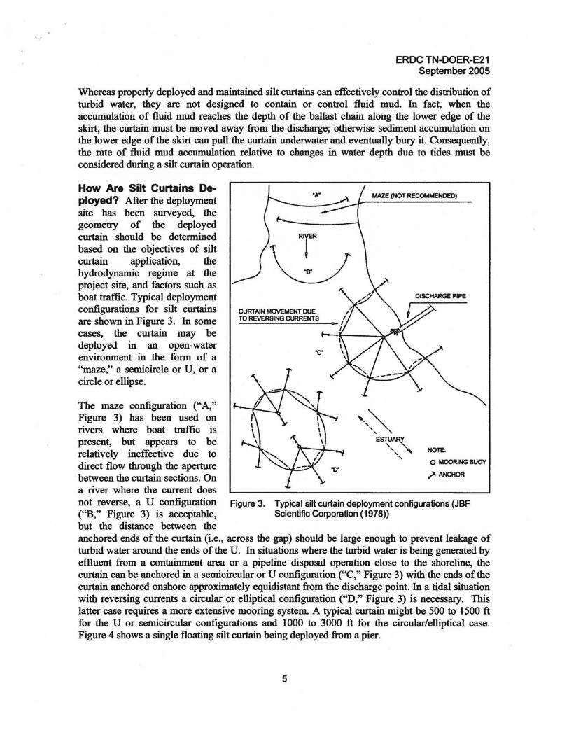
How Are Silt Curtains Deployed? After the deployment site has been surveyed, the geometry of the deployed curtain should be determined based on the objectives of silt curtain application, the hydrodynamic regime at the project site, and factors such as boat traffic. Typical deployment configurations for silt curtains are shown in Figure 3. In some cases, the curtain may be deployed in an open-water environment in the form of a "maze," a semicircle or U, or a circle or ellipse.
The maze configuration ("A," Figure 3) has been used on rivers where boat traffic is present, but appears to be relatively ineffective due to direct flow through the aperture between the curtain sections. On a river where the current does not reverse, a U configuration ("B," Figure 3) is acceptable, but the distance between the anchored ends of the curtain (i.e., across the gap) should be large enough to prevent leakage of turbid water around the ends of the U. In situations where the turbid water is being generated by effluent from a containment area or a pipeline disposal operation close to the shoreline, the curtain can be anchored in a semicircular or U configuration ("C," Figure 3) with the ends of the curtain anchored onshore approximately equidistant from the discharge point. In a tidal situation with reversing currents a circular or elliptical configuration ("D," Figure 3) is necessary. This latter case requires a more extensive mooring system. A typical curtain might be 500 to 1500 ft for the U or semicircular configurations and 1000 to 3000 ft for the circular/elliptical case. Figure 4 shows a single floating silt curtain being deployed from a pier.
CURTAIN MOVEMENT DUE TO REVERSING CURRENTS
"C.
NOTE:
o MOORING BUOY
.)I ANCHOR
Figure 3. Typical silt curtain deployment configurations (JBF Scientific Corporation (1978»
5

EROC TN-OOER-E21 September 2005
What Types of Silt Curtains Are Commercially Available for Silt Curtains? Many types of commercially available silt curtains are manufactured to perform specific functions. Names given by the manufacturers to describe the silt curtains include "floating," "floating diversion baffie," "fixed banging," "penneable," "standing," "frame," "sinkable hanging," and "combination." Other names refer to the type of water or current where the curtain will be used Figure 4. Single flotation silt curtain being deployed from (e.g., slack, slow, medium, fast, shoreline (Courtesy of Marke Wilkie, Elastecl rough, tidal, etc.). American Marine, Inc., 401 Shearer Blvd., Cocoa,
FL32922)
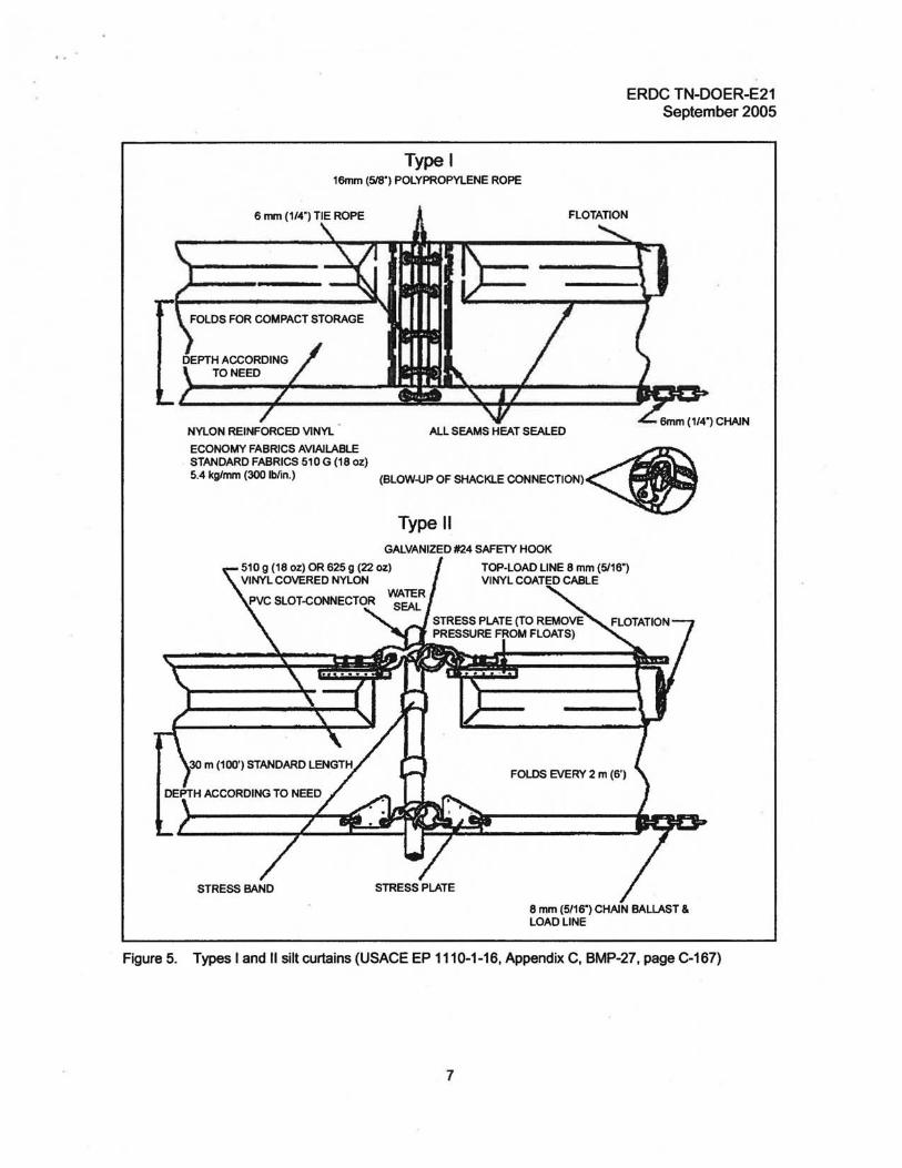
Typical silt curtain types are shown in Figures 5 and 6. Most silt curtains incOlporate the following common specification components:
• Flotation or buoyancy (e.g., solid or compressed air). • Skirt depth (height between the top boom and the curtain bottom). • Fabric (e.g., tensile strength, tear strength, abrasion resistance, material, coating, weight,
seams/seals, drains, and color-bright yellow or international orange are recommended). • Connectors (e.g., lace, bolt through, ASTM universal, PVC slotted tube, hook and O-ring). • Ballast (e.g., type and weight). • Tension member or load line (i.e., upper, mid, or bottom).
What Is Known about the Effectiveness of Silt Curtains? Silt curtains have been evaluated since the early 1970's. One of the most definitive early studies on the functional capabilities and performance of silt curtains in the United States was completed by JBF Scientific Corporation (1978) during the Corps of Engineers' Dredged Material Research Program. The study consisted of evaluating past and present uses, effectiveness of various applications, deployment guidelines and specifications, deployment methods, and environmental conditions that might limit the use of silt curtains. Much of the technical guidance presented in the study report is still valid and represents a fundamental source of information currently used by silt curtain design practitioners. Summarizing the JBF Scientific Corporation study, silt curtain effectiveness depends on many factors such as:
• Nature of the operation (i.e., navigation or environmental dredging). • Quantity and type of material in suspension within or upstream of the curtain (including
debris, oils, and chemicals). • Characteristics, construction, and condition of the curtain as well as the area and
configuration of the barrier enclosure (e.g., partial or full depth containment, either solid or permeable).
6
ERDC TN-DOER-E21 September 2005
Type I 16mm (518") POLYPROPYLENE ROPE
NYLON REINFORCED VINYL
ECONOMY FABRICS AVIAILABLE STANDARD FABRICS 510 G (18 oz) 5.4 kglmm (300 Ib/in.)
STRESS BAND STRESS PLATE
TOP"LOAD LINE 8 mm (5116") VINYL COATED CABLE
FOLDS EVERY 2 m (6')
Figure 5. Types I and II silt curtains (USACE EP 1110-1-16, Appendix C, BMP-27, page C-167)
7
ALL SEAMS HEAT SEALED
(Blow.tJP OF SHACKlE CONNECTION)~ Type II
GALVANIZED #24 SAFETY HOOK
8 mm (5/16") CHAIN BALLAST & LOAD LINE
EROC TN-OOER-E21 September 2005
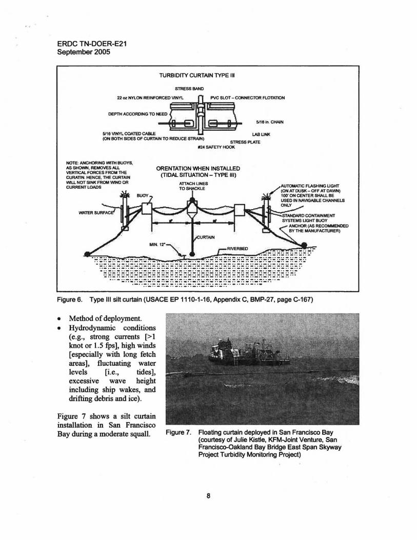
TURBIDITY CURTAIN TYPE III
STRESS BAND
22 oz NYLON REINFORCED VINYL PVC SLOT - CONNECTOR FLOTATION
DEPTH ACCORDING TO NEED
5116 In. CHAIN
5116 VINYL COATED CABLE LABUNK (ON BOTH SIDES OF CURTAIN TO REDUCE STRAIN)
STRESS PlATE ~4 SAFETY HOOK
NOTE: ANCHORING WITH BUOYS, AS SHOWN, REMOVES ALL ORENTATION WHEN INSTALLED VERTICAL FORCES FROM THE (TIDAL SITUATION - TYPE III)CURATIN. HENCE. THE CURTAIN WILL NOT SINK FROM WINO OR ATIACHUNES CURRENT LOADS AUTOMATIC FLASHING UGHT
TO SHACKLE /'(ON AT DUSK - OFF AT DAWN)
100' ON CENTER SHALL BE USED IN NAVIGABLE CHANNELS ONLY
RIVERBED
.. _.._.. _.._.. _.._.. _.. - .. _..... _.. _.. _.. _.. ·._.. _.. - .. _.0 _.. _.._.. _.. _.. _.. _•. _.0 _.. __ .._.. _.. _.0 _...__.. ..._..-_ ... .. --.. _.. _ .. _ .. _.0 _.. _ .. _ .. _.. _ .. _,._,0 _ .. _ .. _.. "._'0 _ .. _ .. _.... _.. _... _.. · '_'._ .. - .. _.0 _.. _.. _.. _.. _.. _.. _.. _.. _.. __.. _ .'_"_.'. ... _.. _.. - _.. _.. _.. _.0 _.. _.. _.. _.. _.. _.. _.. _.. _.. _..... _.. _.. _.. _0'_ •• _ •• _ •• _ •• _ •• _ ... _ •• _ •• _ •• _ •• _ •• _ •• _ •• __ •• _ •• _ •• _... _.._.. _..._.. _.. - _.. _.. _.. _.. -.. -.. _.. _.._.. _.. _.. - .. -.. _...._'. _. ,- ." ..-"-"-" · ._ .. _.. _ .. _ .. _ .. _ •. _ .. _ .. _ .. _.. _ .. _ .. _ ... __ .. _... _.4 .._.. _ _.... _.._.. _.._.. _ -.. .. _.. -.. _.._.. _.._.. _.._.. _.._.. _.._.. _.. - .. _ -... .. _.._.. - _.. _.. _.. _.. _.. -... -.. _.. _.. _.. - ... _.. -.. - ... _-.'-'. - .. _.. _.. _.. _.. _.. -.. _..
Figure 6. Type III silt curtain (USACE EP 1110-1-16, Appendix C, BMP-27, page C-167)
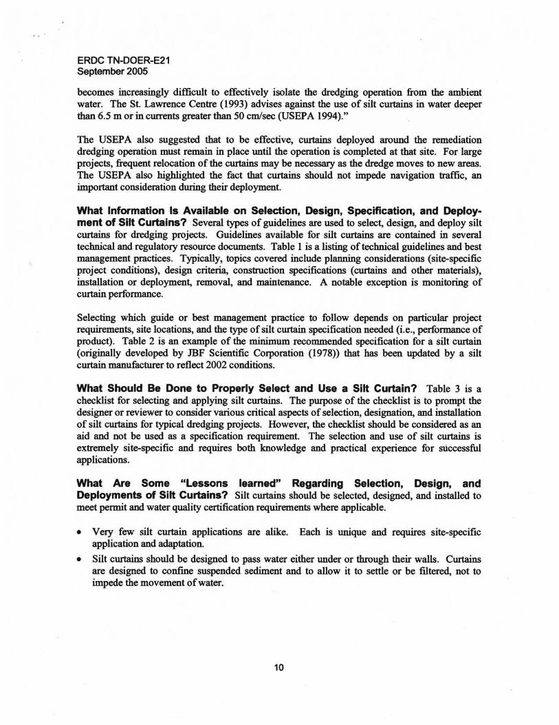
• Method of deployment. • Hydrodynamic conditions
(e.g., strong currents [>1 knot or 1.5 fps], high winds [especially with long fetch areas], fluctuating water levels [i.e., tides], excessive wave height including ship wakes, and drifting debris and ice).
Figure 7 shows a silt curtain installation in San Francisco
Figure 7. Floating curtain deployed in San Francisco Bay Bay during a moderate squall. (courtesy of Julie Kistle, KFM-Joint Venture, San Francisco-Oakland Bay Bridge East Span Skyway Project Turbidity Monitoring Project)
8

ERDC TN-DOER-E21 September 2005
JBF Scientific Corporation (1978) defined effectiveness as "the degree of turbidity reduction outside the curtain relative to the turbidity levels inside the curtain enclosure." They also concluded that:
In some cases, turbidity levels in the water column outside the curtain can be 80-90 percent lower than levels inside or up-current of the curtain enclosure. High currents and energy environments cause silt curtains to flare, thus reducing the curtain's effective depth. At a current of 1 knot, the effective skirt depth ofa l.5-m curtain is approximately 0.9 m. Increased turbulence around the curtain also tends to cause resuspension of the fluid mud layer and may cause increased turbidity levels in the upper water column beyond the curtain. Tidal currents that dominate the hydrodynamic regime may cause the fluid mud to be resuspended, especially if the curtain is not properly deployed. Frequently, changes in the direction of the current will dominate the direction and movement (flapping) of an improperly anchored curtain. Where anchoring is inadequate and particularly at sites where tidal currents dominate the hydrodynamic regime and probably cause resuspension of the fluid mud as the curtain sweeps back and forth over the fluid mud with changes in the direction of the tidal currents, the turbidity levels outside the curtain can be higher (as much as 10 times) than the levels inside the curtain.
Finally, JBF Scientific Corporation (1978) stated, "With respect to overall effectiveness and deployment considerations a current velocity of approximately 1 knot appears to be a practical limiting condition for silt curtain use."
In preparation for the construction of the Westway interstate highway in New York, a test program was established to determine the effectiveness and deployment configurations needed for the dredging activities associated with the highway construction project. Lawler, Matusky, and Skelly Engineers (1983) reported the results of the water quality tests performed on the prototype silt curtains used in the test program. They concluded, "Visual observations and field measurements showed the silt curtain to be an effective barrier to currents, dye, suspended solids, and turbidity. The curtain did not function as a permeable fabric as predicted; water appeared to flow around it rather than through it." The silt curtain contained most contaminants with the exception of ammonia. Mixing outside the curtain in the water column brought the levels down to background levels. Lawler, Matusky, and Skelly Engineers also concluded, "The low currents measured behind the curtain indicated that the curtain blocks flow patterns and creates a quiescent zone. The lack of flow through the curtain is probably attributable to the water taking the path of least resistance (i.e., under the piers or around the ends). Clogging of the curtain with suspended solids (either background or caused by dredging) would only aggravate this situation." At the time, the concept of enclosing a dredge was new and untested. Notably, a concern arose that enclosing the dredge with a silt curtain would create a settling basin for solids that could promote the concentration and release of oxygen-consuming suspended contaminants in violation of water quality stan<4trds. The exchange of water inside the curtain became a design topic and relief panels (flaps) were considered to allow a 25-percent exchange of basin volume over a 12-br period.
In 1994, the USEP A published a remediation guidance document as part of the Assessment and Remediation of Contaminated Sediments (ARCS) Program (US EPA 1994). They concluded, "As a generalization, silt curtains and screens are most effective in relatively shallow quiescent water. As the water depth increases and turbulence caused by currents and waves increases, it
9
EROC TN-OOER-E21 September 2005
becomes increasingly difficult to effectively isolate the dredging operation from the ambient water. The St. Lawrence Centre (1993) advises against the use of silt curtains in water deeper than 6.5 m or in currents greater than 50 cm/sec (USEPA 1994)."
The USEP A also suggested that to be effective, curtains deployed around the remediation dredging operation must remain in place until the operation is completed at that site. For large projects, frequent relocation of the curtains may be necessary as the dredge moves to new areas. The USEP A also highlighted the fact that curtains should not impede navigation traffic, an important consideration during their deployment.
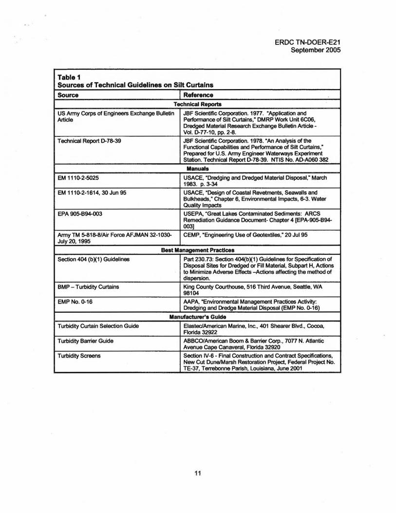
What Information Is Available on Selection, Design, Specification, and Deployment of Silt Curtains? Several types of guidelines are used to select, design, and deploy silt curtains for dredging projects. Guidelines available for silt curtains are contained in several technical and regulatory resource documents. Table 1 is a listing of technical guidelines and best management practices. Typically, topics covered include planning considerations (site-specific project conditions), design criteria, construction specifications (curtains and other materials), installation or deployment, removal, and maintenance. A notable exception is monitoring of curtain performance.
Selecting which guide or best management practice to follow depends on particular project requirements, site locations, and the type of silt curtain specification needed (i.e., performance of product). Table 2 is an example of the minimum recommended specification for a silt curtain (originally developed by IDF Scientific COIporation (1978» that has been updated by a silt curtain manufacturer to reflect 2002 conditions.
What Should Be Done to Properly Select and Use a Silt Curtain? Table 3 is a checklist for selecting and applying silt curtains. The pUtpose of the checklist is to prompt the designer or reviewer to consider various critical aspects of selection, designation, and installation of silt curtains for typical dredging projects. However, the checklist should be considered as an aid and not be used as a specification requirement. The selection and use of silt curtains is extremely site-specific and requires both knowledge and practical experience for successful applications.
What Are Some "Lessons learned" Regarding Selection, DeSign, and Deployments of Silt Curtains? Silt curtains should be selected, designed, and installed to meet permit and water quality certification requirements where applicable.
• Very few silt curtain applications are alike. Each is unique and requires site-specific application and adaptation.
• Silt curtains should be designed to pass water either under or through their walls. Curtains are designed to confine suspended sediment and to allow it to settle or be filtered, not to impede the movement ofwater.
10
ERDC TN-DOER-E21 September 2005
Table 1 Sources of Technical Guidelines on Silt Curtains
Source Reference Technical Reports
US Army Corps of Engineers Exchange Bulletin Artide
JBF Scientific Corporation. 19n. "Application and Performance of Silt Curtains," DMRP Work Unit 6C06, Dredged Material Research Exchange Bulletin Artide Vol. D-n-10, pp. 2-8.
Technical Report D-78-39 JBF Scientific Corporation. 1978. "An Analysis of the Functional Capabilities and Perfonnance of Silt Curtains," Prepared for U.S. Anny Engineer Waterways Experiment Station. Technical Report D-78-39. NTIS No. AD-A060 382
Manuals
EM 111 ~2-5025 USACE, "Dredging and Dredged Material Disposal,· March 1983. p. 3-34
EM 111~2-1614, 30 Jun 95 USACE, "Design of Coastal Revetments, Seawalls and Bulkheads," Chapter 6, Environmental Impacts, 6-3. Water Quality Impacts
EPA 905-B94-oo3 USEPA, "Great Lakes Contaminated Sediments: ARCS Remediation Guidance Document- Chapter 4 [EPA-905-B94003]
Anny TM 5-818-8/Air Force AFJMAN 32-10~ July 20, 1995
CEMP, "Engineering Use of Geotextiles," 20 Jul95
Best Management Practices
Section 404 (bX1) Guidelines Part 230.73: Section 404(bX1) Guidelines for Specification of Disposal Sites for Dredged or Fill Material, Subpart H, Actions to Minimize Adverse Effects -Actions affecting the method of dispersion.
BMP - Turbidity Curtains King County Courthouse, 516 Third Avenue, Seattle, WA 98104
EMPNo. ~16 AAPA, "Environmental Management Practices Activity: Dredging and Dredge Material Disposal (EMP No. ~16)
Manufacturer'S Guide
Turbidity Curtain Selection Guide ElasteclAmerican Marine, Inc., 401 Shearer Blvd., Cocoa, Florida 32922
Turbidity Barrier Guide ABBCO/American Boom & Barrier Corp., 70n N. Atlantic Avenue Cape Canaveral, Florida 32920
Turbidity Screens Section IV-6 - Final Construction and Contract Specifications, New Cut DunelMarsh Restoration Project, Federal Project No. TE-37, Terrebonne Parish, louisiana, June 2001
11

...
ERDC TN-DOER-E21 September 2005
Table 2 Recommended Silt Curtain Specifications1
,2
Parameter Recommended Value Skirt Depth Up to 100 ft maximum allowing 1-2 ft dearance between skirt and bottom
Fabric
Tensile strength grab 500 Iblin.
Tear strength strip 180z 220z
320 Ib - quiescent conditions 400 Ib - medium to high current
Abrasion resistance 200 Iblin. tensile strength after abrasion
Material Polyester
Coating PVC
Weight 18-22 oz (depending on type of curtain design)
Seams Heat sealed
Buoyancy
Ratio >5
Type Solid, dosed cell, and enclosed in a fabric pocket
Connector Load transfer type - aluminum extrusion
. Ballast
Type Noncorrosive galvanized chain
Weight See Figures 16 and 17
Tension Member
No current Fabric only
Current (0.1-1.0 knots Top or center tension; center tension provides slightly greater effective skirt depth
1 In 2002, a 100-ft section of silt curtain with top tension member to the above specifications and a skirt depth of 5 ft could be purchased at an approximate cost of $1,100.00.
2 Source: ElasticlAmerican Marine, 401 Shearer Blvd., Cocoa, FL 32922 USA, Tel: 321-636-5783, Fax: 321-6365787, E-mail: [email protected], www.elastec.com.
Table 3 Checklist for Selection and Application of Silt Curtains
1) Pre-dredglng Site Survey
a) Have background conditions at the site been established?
b) Has the site been adequately characterized with respect to
i) Current velocity, water depth (relative to tidal range)?
ii) Bottom sediment types?
iii) Background levels of turbidity?
Y_N_N/A_
Y_N_N/A_
Y_N_N/A_
Y_N_NlA_
Y_N_NlA_
(Sheet 1 of4)
12
EROC TN-OOER-E21 September 2005
Table 3 (Continued)
2) Deployment
a) Have maximum surface currents over a tidal cycle (12 or 24 hr) been established first to detennine types of deployment configurations that may be needed?
b) Have direction of current and water turbulence been defined?
c) Have the minimum water depths been established at the lowest low tide?
d) Has a minimum O.5-m skirt depth been established between the lower edge of the skirt and the existing bottom of the disposal area at the lowest low tide during the operations?
e) Have the effects of fluid mud accumulation on water depth as well as the proposed schedule for moving the silt curtain to prevent burial been considered when selecting the curtain skirt depth?
f) Is the character of the bottom sedimentlvegetation known?
g) Have traffic- and boat-generated waves been detennined?
h) Are locations of launching ramps, crane services, etc. known?
i) Have deployment geometry and COnfl9urations been determined for the site?
j) Have curtain deployment lengths been established?
k) Have different anchor types been considered?
I) Have different curtain configurations been considered (e.g., U, V, circular, elliptical)?
3) Slit CurtaIn Specifications
a) Does the lower edge of the silt curtain extend a minimum of 0.5 m from the bottom at lower tide?
b) Is skirt depth less than the recommended 3 m?
c) Has fabric material been selected (PVC or equivalent) with a minimum tensile strength of 525 N/m?
d) Has the fabric weight (minimum of 610 g/m2 for low current conditions, and 746-g/m2 for high current conditions) been designated?
e) Has a tear strength (min of 445 for 610-g fabric or 890 N for 746-g fabric been designated?
f) Has a tensile strength after abrasion (greater than 350 N/m) been designated?
g) Has a material been selected that is easily cleaned and resistant to marine growth, ultraviolet light, and mildew?
h) Are all fabric seams heat-sealed or equivalent?
i) Has flotation been designated as sections of solid, closed-cell, plastic foam flotation material sealed into a fabric pocket that provide a buoyancy ratio (buoyant force/curtain weight) greater than 5?
j) Is each flotation segment a minimum of 3 m in lerJgth so the curtain may be easily folded for storage or transport?
k) Do connectors in low currents «0.1 knot) maintain adequate physical contact along the entire skirt joint?
Y_N_NlA_
Y_N_N/A_
Y_N_N/A_
Y_N_NlA_
Y_N_NlA_
Y_N_NlA_
Y_N_NlA_
Y_N_NlA_
Y_N_N/A_
Y_N_N/A_
Y_N_N/A_
Y_N_N/A_
Y_N_NlA_
Y_N_NlA_
Y_N_NlA_
Y_N_NlA_
Y_N_NlA_
Y_N_N/A_
Y_N_N/A_
Y_N_NlA_
Y_N_NlA_
Y_N_NlA_
Y_N_NlA_
(Sheet 2 of4)
13

EROC TN-OOER-E21 September 2005
Table 3 (Continued)
3) Slit Curtain Specifications - (continued) I) Have aluminum extrusion (or equivalent) load-transfer connectors
been designated for current velocities exceeding 0.1 knot?
m) Have non-conosive ballast chains with a weight ranging from approximately 1.5 kg/m for a 1.5-m skirt depth up to 3.0 kg/m for a ~ skirt depth been selected?
n) Are tension members used as follows:
i) Negligible current: no tension member?
ii) Current velocities between 0.1 and 1.0 knot?
iii) Galvanized or stainless steel wire rope as top or center tension member?
0) Have hand holds been designated along the top of the curtain between the flotation segments for ease in handling?
p) Have repair kits been designated to patch minor tears in the fabric?
4) Transportatlona) Have furls (lightweight straps or rope) been specified every 1 to 1.5 m
from storage to unloading site?
b) Has curtain been specified to be compactly folded accordion style, packaged into large bundles, and carefully lifted into transportation vehide?
c) Will curtains be unloaded like a string of sausages and connected in appropriate sections (up to 30 m) as they are played out of the vehide?
d) Will curtains be towed by boat (traveling at 2 to 3 knots) to the deployment site?
e) Will the curtain be kept furled except near the end of the connectors until it has been deployed at the site?
5) Moorlng
a) Has the recommended mooring system consisting of an anchor, chain, an anchor rode (line or cable), and mooring and crown buoys been designated?
b) Has the anchor pattern been designated based on the curtain deployment geometry site conditions (e.g., from section joints every 30 m in a radial pattern and on both sides if the curtain is exposed to reversing tidal currents)?
c) Have sizes (e.g., ~ -inch etc.) of anchor lines and anchor weights (e.g., 4.5 kg for sandy bottoms and up to 34 kg for firm mud) been selected based on bottom conditions.?
Y_N_NlA_
Y_N_N/A_
Y_N_NlA_
Y_N_N/A_
Y_N_NlA_
Y_N_NlA_
Y_N_NlA_
Y_N_N/A_
Y_N_N/A_
Y_N_N/A_
Y_N_NlA_
Y_N_NlA_
Y_N_NlA_
Y_N_NlA_
Y_N_NlA_
(Sheet 3 of4)
14

-. '
ERDC TN-DOER-E21 September 2005
Table 3 (Concluded)
6) Deployment Model-
a) Has the length of time for deployment before reconfiguration or movement been determined based on accumulation of fluid mud inside the curtain relative to the deployment geometry, the discharge (filling) rate, and the initial bottom gap (Le., the distance between the lower skirt edge and the bottom sediment at the beginning of the operation)?
b) Is the total length of the curtain available for the project adequate for the size of the enclosure?
7) Maintenance Has adequate attention been given to a) Moving the curtain away from the turbidity sources just before the
fluid mud layer reaches the lower edge of the skirt?
b) Replacing worn or broken anchor lines?
c) Maintaining the integrity of the curtain by repairing leaking connectors and / or tears in the curtain fabric?
d) Repairing tears in the flotation pocket with hand-type pop rivet gun and rivets?
e) Repairing moderate tears in skirts on land with vinyl/nylon repair kit and VINYLFIX or PVC glue?
f) Keeping one or two spare sections of curtain for immediate replacement of unrepairable sections onsite?
8) Recovery-
a) Will silt curtains be retuned after operations are completed?
b) Will anchor/moOring systems be recovered?
c) Will the curtains be returned to the launching site for repacking and subsequent storage?
9) Monitoring a) Have plans been made for monitoring during dredging operations?
b) Will measurements of turbidity (NTU) and samples for TSS (mg/L) be taken on both sides of the silt curtain near the dredging operations and near any sensitive habitat?
c) Will tide, wind, wave, and current measurements be made?
d) Are there plans to monitor post-dredging operations with respect to limited measurements of current, tidal range, winds, turbidity (NTU), and samples for TSS (mg/L) for comparison with background conditions?
Y_N_NlA_
Y_N_NlA_
Y_N_NlA_
Y_N_N/A_
Y_N_NlA_
Y_N_N/A_
Y_N_N/A_
Y_N_N/A_
Y_N_N/A_
Y_N_NlA_
Y_N_NlA_
Y_N_N/A_
Y_N_N/A_
Y_N_N/A_
Y_N_N/A_
(Sheet 4 of4)
• In applications where the curtain will be extended to the bottom of the waterway in tidal or moving water conditions, a heavy woven permeable filter fabric or tide flaps should be designed into the curtain to relieve pressure on the curtain wall.
• In,general, silt curtains should be used on slow to moderate currents, stable water levels, and relatively shallow water depths.
15

ERDC TN-DOER-E21 September 2005
• Currents greater than 1 to 1-112 knots are problematic, leading to difficult and often expensive curtain designs. Silt curtains should not be used in current velocities greater than 3-5 knots unless there are unusual circumstances and special designs are considered. Curtain deployments for deep, fast-flowing water and windy conditions require customized designs. However, for all practical purposes, the 1 to 1-112 knot value appears to be an industry standard.
• In slow currents, resuspension and turbidity are localized, so a fundamental question is whether or not a silt curtain is even necessary.
• In high currents where sediment plumes disperse rapidly, silt curtains are very difficult to maintain properly and can easily become dysfunctional.
• In all but the slowest current flows, curtains will "billow out" in the downstream direction, allowing water to pass beneath the curtain, thereby reducing the effective skirt depth.
• Extra length (up to 10-20 percent) and depth (slack) of curtains should be included in designs to allow for tidal fluctuations and exchanges of water within the curtain.
• Special designs may be required for applications of curtains at depths greater than 10-15 ft or with currents exceeding 1-112 knots, particularly in tidal waters. At greater depths, loads or pressures on curtains and mooring systems become excessive and could result in failure of standard construction materials.
• High winds can lift large curtains out of the water like a sail.
• Curtains can sink due to excessive biological fouling on the fabric.
• An attempt should be made to minimize the number of joints in the curtain; a minimum continuous span of 15 m (50 ft) between joints is a "good rule of thumb."
• Curtains should be a bright color (yellow or "international" orange are recommended) to enhance visibility for boaters.
• In tidal situations, where currents move in both directions, it is important to attach ·anchors on both sides of the curtain to hold the curtain in place and to not allow it to overrun the anchors and pull them out when the tide reverses.
• Anchor lines should be attached to the flotation device, not to the bottom of the curtain.
• Care should be taken during removal of silt curtains to avoid or minimize resuspension of settled solids.
• Removal of settled solids trapped by the silt curtain is optional and should only be considered if the resulting bottom contour elevation is significantly altered.
• When dredging contaminated sediment, installing silt curtains within continuous or intermittent sheetpile walls to provide anchoring points has proven to be more effective than using silt curtains alone.
• Silt curtains can be effective in containing floating debris, but not always in containing contamination. Soluble contaminants, particularly heavy metals, can flow through, around, or under the curtain.
• Aquatic habitat can be successfully protected with deflection curtains provided they are properly designed and deployed, taking into consideration site-specific conditions.
• Designs should conform to relevant contract specifications and manufacturer recommendations and guidelines for installation and safety measures.
16
ERDC TN-DOER-E21 September 2005
• Silt curtains should not be considered a "one solution fits all" type of best management practice. They are highly specialized, temporary-use devices that should be selected only after careful evaluation of the intended function and designed based upon a detailed knowledge of the site where they will be used.
SUMMARY: The term "silt curtain" is used to describe devices deployed in water to control suspended solids or turbidity resulting from dredging operations. Almost every silt curtain application has unique features that require site-specific adaptations. Several sources of published technical guidelines and best management practices are identified and referenced in this note. Typical topics covered in these guides include planning considerations (site-specific project conditions), design criteria, construction specifications (curtains and other materials), installation or deployment, removal, and maintenance. A notable exception is monitoring of silt curtain performance.
For cost considerations, logistical constraints, and performance expectations, prevailing current velocities of 1 to 1-112 knots effectively limit deployments, with exceptions on a case-by-case basis. Unfortunately, few comprehensive studies are published on the actual performance of silt curtains under varying project conditions. Additional monitoring studies will be required to properly document the functional characteristics and incremental costs of silt curtains under demanding project conditions ofmoderate to high currents, winds, and waves.
Silt curtains should not be considered a "one solution fits all" type of best management practice. They are highly specialized, temporary-use devices that should be selected only after careful evaluation of the intended function and designed based on a detailed knowledge of the site where they will be used.
POINTS OF CONTACT: For additional information, contact the authors, Mr. Norman R. Francingues (601-636-3805, [email protected]) of OA Systems Corporation, or Dr. Michael R. Palermo (601-831-5412, [email protected]) of Mike Palermo Consulting, or Dr. Robert M. Engler (601-634-3624, Robert.M. [email protected]), manager of the Dredging Operations and Environmental Research Program. This technical note should be cited as follows:
Francingues, N. R., and Palermo, M. R. (2005). "Silt curtains as a dredging project management practice," DOER Technical Notes Collection (ERDC TN-DOER-E21). U.S. Army Engineer Research and Development Center, Vicksburg, MS. http://el.erdc.usace.army.milldots/doer/doer.html.
REFERENCES
JBF Scientific Corporation. (1978). "An analysis of the functional capabilities and perfonnance of silt curtains," Technical Report D-78-39, U.S. Anny Engineer Waterways Experiment Station, Vicksburg, MS.
Johanson, E. E. (1976). "The effectiveness of silt curtains in controlling turbidity." Proceedings o/the th World Dredging Congress.
17
ERDC TN-DOER-E21 September 2005
Johanson, E. E. (1977). "Application and perfonnance of silt curtains." Dredged Material Research, U.S. Anny Corps of Engineers Infonnation Exchange Bulletin, Vol. D-77-lO, U.S. Anny Engineer Waterways Experiment Station, Vicksburg, MS, 1-8.
Lawler, Matusky, and Skelly Engineers. (1983). "Results of water quality tests in prototype silt curtain testing program - Westway Project." LMSE-83/0161&232/019, LMS Environmental Science and Engineering Consultants, Pearl River, NY.
Reine, K. J., Dickerson, D. D., and Clarke, D. G. (1998). "Environmental windows associated with dredging operations," DOER Technical Notes Collection (TN OOER-E2). U.S. Anny Engineer Research and Development Center, Vicksburg, MS. http://el.erdc.usace.army.milldotsldoer/doer.html.
NOTE: The contents ofthis technical note are not to be used for advertising, publication, orpromotional purposes. Citation oftrade names does not constitute an official endorsement or approval ofthe use ofsuch products.
18