SIBELSOUND 400 - Sjukvårdsutrustning, medicinteknik ... · LUSCHER TEST PROCEDURE.....91 1.15....
191
SIBELSOUND 400 520-700-MU2 • REV. 1.01 USER MANUAL AUDIOMETRY
Transcript of SIBELSOUND 400 - Sjukvårdsutrustning, medicinteknik ... · LUSCHER TEST PROCEDURE.....91 1.15....

SIBELSOUND 400
520-700-MU2 • REV. 1.01
USER MANUAL
AUDIOMETRY

SIBEL S.A., Rosselló 500, 08026 Barcelona - EspañaNational Sales: Tel. 93 436 00 08 e-mail: [email protected] Internacionales/International Sales:Tel. +34 93 436 00 07e-mail: [email protected] serv.: Tel. +34 93 433 54 50e-mail: [email protected]: +34 93 436 16 11 , Web: www.sibelmed.com
Contents
� Instruction manual
ÍNDICE
DECLARATION OF CONFORMITY ........................................ 7
SAFETY .............................................................................. 9
1. INSTRUCTIONS FOR INSTALLATION AND USE ............. 13
1.1 INTRODUCTION ......................................................... 14
1.2. INTRODUCTORY INFORMATION ............................... 15
1.3. SIBELSOUND 400 AUDIOMETER MODELS .................. 16
1.4. LAYOUT OF CONTROLS, INDICATORS AND
CONNECTORS .................................................................. 20
1.5. INSTALLATION AND START-UP ................................. 24
1.6. FUNCTION TREE ....................................................... 30
1.7. PERSONALISING THE DEVICE ................................... 32
1.8. AUDIOMETRIC TESTS ............................................... 45
1.9. PROCEDURE FOR TONE AUDIOMETRY ...................... 50
1.10 PROCEDURE FOR SISI TEST .................................... 66
1.11. PROCEDURE FOR SPEECH AUDIOMETRY TEST ........ 73
1.12. PROCEDURE FOR PERFORMING THE FOWLER TEST . 80
1.13. TONE DECAY TEST PROCECURE ............................... 85
1.14. LUSCHER TEST PROCEDURE .................................... 91
1.15. WEBER TEST PROCEDURE ....................................... 97
1.16 PURE TONE HF TEST PROCEDURE .......................... 103
1.17. PROCEDURE FOR FREE AUDIOMETRY .................... 109
1.19. PRINTING AND SAVING AUDIOMETRIC TESTS...... 111
1.20. COMMUNICATIONS SYSTEMS ............................... 125
1.21. UPDATING THE UNIT FIRMWARE .......................... 128
1.22. MAINTENANCE PROGRAM ..................................... 129
2. TECHNICAL SPECIFICATIONS .................................... 141
2.1 TYPES OF TESTS ...................................................... 142
2.2. SIGNAL GENERATORS ............................................. 142
2.3. CONTROL OF SIGNAL LEVELS ................................ 145

Con
tent
s
� Instruction manual
2.4. OTHER FUNCTIONS ................................................. 146
2.5. TRANSDUCERS ........................................................ 147
2.6. APPLICABLE STANDARDS ....................................... 147
2.7. GENERAL DATA ....................................................... 149
3. OPERATING PRINCIPLES ........................................... 151
3.1. RIGHT / LEFT CHANNEL ......................................... 154
3.2. MICROPROCESSOR ................................................. 155
3.3. INTERCOM (Optional) ............................................. 157
3.4. FREE FIELD (Optional) ............................................ 157
4. AUDIOMETRY TECHNIQUE ......................................... 159
5. UPKEEP, PREVENTIVE, CORRECTIVE MAINTENANCE .. 161
5.1. UPKEEP .................................................................. 162
5.2. PREVENTIVE MAINTENANCE ................................... 163
5.3. CORRECTIVE MAINTENANCE ................................... 165
6. MODIFICATIONS ....................................................... 167
APPENDIX 1 .................................................................. 169
ELECTROMAGNETIC COMPATIBILITY ............................. 169
APPENDIX 2 .................................................................. 175
COMPLIANCE WITH THE DATA PROTECTION
ACT. DIRECTIVE 95/46/EC ............................................ 175
APPENDIX 3 .................................................................. 178
CALCULATION TABLES FOR DIAGNOSES ........................ 178

Contents
� Instruction manual

Con
tent
s
� Instruction manual

Declaration of C
onformity
� Instruction manual
DECLARATION OF CONFORMITY
The SIBELSOUND 400 Audiometer has been designed and manufactured in accordance with the SIBEL S.A. Quality Manual which complies with quality standard EN ISO 13485:2004 and ISO 9001:2000, as well as with European Medical Devices Directive 93/42/EEC. In accordance with the latter directive this is a class IIa device. It also complies with the following standards:
EN – 60601-1 Safety of Electrical Equipment EN – 60601-1-1 Safety of Medical Systems EN – 60601-1-2 Electromagnetic Compatibility EN – 60601-1-4 Programmable systems EN – 60645-1 Pure tone audiometry EN – 60645-2 Speech audiometers EN – 60645-4 High frequency audiometry
Revised ApprovedDate: January 2009 Date: January 2009
José Maria Plana Carlos RecioTechnical Director Sales Director
PRODUCT CONFORMS WITH93/42/EEC Medical Devices DirectiveClass II a

� Instruction manual
Dec
lara
tion
of C
onfo
rmity
� Instruction manual

Safety
� Instruction manual
SAFETY
SPECIAL PRECAUTIONS
The SIBELSOUND 400 audiometer has been designed to the highest safety standards.You should read all operating instructions carefully before operating the device. Failure to do so could cause injury to the user or patient and damage to the equipment and/or accessories.
INTENDED USE
The audiometer generates a series of acoustic and vibrational stimuli and calculates a series of parameters relating to human audiometry.The audiometer is intended for use by medical staff only, under the supervision and instruction of a doctor.The audiometer is not intended for use outdoors, nor in conditions or with energy sources other than as set out in this manual.
THE ROLE OF THE PATIENT IN THE USE OF THE AUDIOMETER
The audiometry tests require the cooperation of the patient. The patient must press a button to communicate the detection of a stimulus. The doctor must evaluate the patient's ability to carry out the audiometry tests. Special care must be taken with children, the elderly and the handicapped.

10 Instruction manual
Safe
ty
10 Instruction manual
LIMITATIONS OF USE. CONTRAINDICATIONS
Interpretation of test results and any resulting treatment must be carried out by a doctor.The medical staff must evaluate any symptoms presented by the patient before any audiometric tests are carried out.The suitability of audiometric testing is the responsibility of the medical staff.The audiometer should not be used when it is likely that the validity of the results could be compromised by external factors.
ELECTRICAL RISKS
DO NOT tamper with the integrity of the system's electric earth connection. Protection against electrical discharge is provided by the connection of the chassis to an electrical earth connection. The earth connection is only effective when the three-wire power cable supplied with the equipment is connected to a suitably earthed electrical socket.
DO NOT use multiple mains sockets, unless they comply with EN-60601-1-1. They can degrade electrical safety.
DO NOT remove the device cover. Servicing and repair of the apparatus must only be carried out by trained personnel. Contact with the voltage inside the system can cause serious injury.
DO NOT use the equipment if the power cable is in poor condition or cracked.
DO NOT use the transducers if they are in poor condition.
NEVER immerse any part of the equipment in liquid. THIS COULD CAUSE AN ELECTRICAL DISCHARGE.
To ensure safety in accordance with standard EN 60601-1-1, only connect equipment which meets current electrical safety standards to this instrument.

Safety
11 Instruction manual
RISK OF EXPLOSION
DO NOT use this equipment in the presence of anaesthetics or inflammable gases. THIS COULD CAUSE AN EXPLOSION.
INTERFERENCE RISK
This is an electronic product, so high frequency emissions can interfere with its correct use. For this reason, products which can cause interference (radios, mobile telephones, etc.) must be kept away from the audiometer.
DISPOSAL OF ELECTRICAL OR ELECTRONIC DEVICES BY DOMESTIC USERS IN THE EUROPEAN UNION
This symbol on the product indicates that it must not be disposed of as part of domestic waste.
Rather, if it is to be disposed of, it is the user's responsibility to take it to a designated recycling point for electrical and electronic devices. The separate collection and recycling of different kinds of waste at the point of disposal helps to preserve natural resources and to ensure that recycling will safeguard health and the environment. If you require further information about where to take products of this type for recycling, contact your local authority, the local domestic waste disposal service or the distributor from whom you purchased the product.

12 Instruction manual
Safe
ty
12 Instruction manual

Chapter 1: Instructions for Installation and U
se
1� Instruction manual
1. INSTRUCTIONS FOR INSTALLATION AND USE

1� Instruction manual
Cha
pter
1: I
nstru
ctio
ns fo
r Ins
talla
tion
and
Use
1� Instruction manual
1.1 INTRODUCTION
The SIBELSOUND 400 clinical audiometer is a compact two-channel device, the main components of which are a tone generator, a noise generator, a set of headphones for air conduction, a vibrator for bone conduction and an alphanumeric liquid crystal screen. The whole system is controlled by a Digital Signal Processor (DSP) that allows audiometric investigation to be carried out quickly, simply and reliably to establish hearing thresholds and to carry out screening tests such as suprathreshold tonal tests.
The SIBELSOUND 400 audiometer has been developed entirely in Spain, based on current technology and more than 20 years experience in the design and manufacture of this kind of equipment. Its functional design and the elimination of most of the electromechanical components have made possible a device that can provide long service in the field of audiometric testing.
The SIBELSOUND 400 audiometer has been designed in collaboration with Barcelona University's Surgery Department (Otorhinolaryngology and Audiology) in the Faculty of Medicine and recognised specialists in the area, and meets the standards criteria of both national (U.N.E) and international institutions (I.E.C., I.S.O., etc.).

Chapter 1: Instructions for Installation and U
se
1� Instruction manual
1.2. INTRODUCTORY INFORMATION
This instruction manual applies to all models and all options which may be included in the SIBELSOUND 400 audiometer. Accordingly, only those functions or options which are found in your particular model will be relevant.
This audiometer is made from professional quality solid state components, under strict quality control. However, accidents can occur during the transport or storage of the equipment. It is therefore advisable to carry out an initial check on its condition, and that of the accompanying accessories, before installation.
WARNINGIF YOU FIND ANY DAMAGE TO THE PACKAGING, YOU SHOULD IMMEDIATELY CONTACT THE TRANSPORT AGENCY AND THE DISTRIBUTOR BEFORE PROCEEDING TO INSTALL. YOU MUST NOT DISCARD THE PACKAGING, BAGS, ETC. BEFORE THOROUGHLY VERIFYING THAT THE EQUIPMENT FUNCTIONS CORRECTLY.

1� Instruction manual
Cha
pter
1: I
nstru
ctio
ns fo
r Ins
talla
tion
and
Use
1� Instruction manual
1.3. SIBELSOUND 400 AUDIOMETER MODELS
The SIBELSOUND 400 audiometer comprises six different models:
SIBELSOUND 400 ASIBELSOUND 400 AMSIBELSOUND 400 AOSIBELSOUND 400 AOMSIBELSOUND 400 AOM+SIBELSOUND 400 SUPRA
The table below shows each model's built-in features as standard (Shadedo) and other items which can be included as optional (White). You can upgrade to a higher model by adding the relevant features at any time. All you need to do is contact the SIBEL S.A. Sales Department or your distributor.

Chapter 1: Instructions for Installation and U
se
1� Instruction manual
RELACIÓN DE CONTENIDO / PACKING LIST Página 1 de 2
SIBELSOUND 400 520-708-010 REV. 4.01 03/02/09
MODELOS / MODELS
CÓDIGOCODE
CANT.QTY.
DESCRIPCIÓN DESCRIPTION
A AM
AO
AOM
AOM+
SUPRA
520-700-___ 1 SIBELSOUND 400 MODELO / MODEL SN: 207-
305-350-020 1 CABLE CONEXIÓN DE RED 2m / MAINS PLUG CABLE 2m
305-600-050 1 CABLE USB TIPO A-B 2.0 / USB CABLE TYPE A-B 2.0
520-540-001 1 CONEXIÓN AVISO PACIENTE / PATIENT SWICHT
520-540-002 1 ARICULARES VIA AEREA / EARPHONE SET
291-500-020 1 SUPRESOR DE RUIDO VA / AUDIOCUPS AC
520-700-MU_ 1 MANUAL DE USO / USER MANUAL:
520-711-GR_ 1 GUIA RAPIDA DE USO / QUICK REFERENCE
520-660-DM0 1 SOFTWARE AUDIOMETRÍA W-50 DEMO/ AUDIOMETRY DEMO SOFTWARE W-50
520-660-LIC
520-66A
520-660-MU_
1
1
1
LICENCIA SOFT. W-50 / W-50 LICENSE SOFT.
SOFTWARE W-50
MANUAL USO /USER MANUAL (Se incluye en el CD)
520-651-010 1 BOLSA DE TRANSPORTE / CARRING BAG
520-760-000
511-690-001
1
1
MODULO RS232 / RS232 MODULE
CABLE RS232 / RS232 CABLE
520-770-000
520-680-002
520-770-002
1
1
1
MODULO MONITOR-INTERCOMUNICADOR Compuesto por : MONITOR MODULE Composed by:
AURICULAR MONITOR / EARPHONE MONITOR
MICROFONO ELECTRET-PINZA /ELECTRET CLIP MICROPHONE
520-780-000
520-770-002
520-770-000
520-680-002
520-770-002
1
1
1
1
1
OPCION FIRMWARE LOGOAUDIOMETRÍA Compuesto por: SPEECHAUDIOMETRY FIRMWARE OPTION Composed by:
MICROFONO ELECTRET-PINZA / ELECTRET CLIP MICROPHONE
MODULO MONITOR-INTERCOMUNICADOR Compuesto por :MONITOR MODULE Composed by:
o AURICULAR MONITOR / EARPHONE MONITOR
o MICROFONO ELECTRET-PINZA /ELECTRET CLIP MICROPHONE
520-790-000
520-790-001
1
1
OPCIÓN FIRMWARE CAMPO ABIERTO/ FREE FIELD
JUEGO ALTAVOCES CAMPO ABIERTO/ FREE FIELD LOUDSPEAKER SET
520-7A0-000
520-7A0-001
1
1
OPCIÓN FIRWARE ALTA FRECUENCIA
AURICULARES ALTA FRECUENCIA/ EARPHONE HIGH FREQUENCY SET
--- --- ---

1� Instruction manual
Cha
pter
1: I
nstru
ctio
ns fo
r Ins
talla
tion
and
Use
1� Instruction manual
RELACIÓN DE CONTENIDO / PACKING LIST Página 2 de 2
SIBELSOUND 400 520-708-010 REV. 4.01 03/02/09
CÓDIGOCODE
CANT.QTY.
DESCRIPCIÓN DESCRIPTION
A AM
AO
AOM
AOM+
SUPRA
520-7B0-000 1 OPCION FIRMWARE FRECUENCIAS INTERMEDIAS INTERMEDIATED FREQUENCY SOFTWARE OPTION
520-7C0-000 1 OPCION FIRMWARE FRECUENCIAS MUSICALES MUSICAL FREQUENCIES FIRMWARE OPTION
520-7D0-000 1 OPCION FIRMWARE ENMASCARAMIENTO SINCRONIZADO AUTOMATIC MASKING FIRMWARE OPTION
520-7E0-000 1 OPCION FIRMWARE TONO REFERENCIA REFERENCE TONE FIRMWARE OPTION --- --- ---
520-7F0-000 1 OPCION FIRMWARE SISIGRAMA SISIGRAM FIRMWARE OPTION
520-7G0-000 1 OPCION FIRMWARE BASE DE DATOS INTERNA INTERNAL DATA BASE FIRMWARE OPTION
520-7H0-000 1 OPCION FIRMWARE PRUEBAS SUPRALIMINARES SUPRALIMINARY FIRMWARE OPTION
520-7I0-000
520-550-001
1
1
OPCIÓN FIRMWARE AUD. TONAL VIA OSEA
VIBRADOR VIA OSEA / BONE VIBRATOR SET
520-7J0-000 1 TONO PULSANTE/ALTERNADO Y MODULADO/ALTERNADO ALTERNATED PULSE TONE AND ALTERNATED MODULE
520-7L0-000 1 OPCION FIRMWARE RUIDO BANDA ESTRECHA NARROW BAND NOISE FIRMWARE OPTION
520-7M0-000 1 OPCION FIRMWARE FRECUENCIA Y AMPLITUD MODULADA FREQUENCY AND AMPLITUDE MODULATION FIRMWARE OPTION
--- --- ---
520-7N0-000 1 OPCION FIRMWARE ENMASCARAMIENTO RUIDO BLANCO MASKING WITH WHITE NOISE FIRMWARE OPTION
520-7O0-000 1 OPCION FIRMWARE ENMASCARAMIENTO RUIDO VOCAL MASKING WITH SPEECH NOISE FIRMWARE OPTION
STANDARD OPCIONAL / OPTIONAL --- NO DISPONIBLE / NOT AVAILABLE
NOTA:- LOS ARTÍCULOS Y CANTIDADES RELACIONADAS ANTERIORMENTE HAN SIDO CUIDADOSAMENTE COMPROBADAS. EN CASO DE FALTAS O DESPERFECTOS PROCEDAN A COMUNICÁRNOSLO LO MAS PRONTO POSIBLE. - SI DETECTA ALGÚN DETERIORO EN EL EMBALAJE, CONTACTE INMEDIATAMENTE CON LA AGENCIA DE TRANSPORTE Y CON SU DISTRIBUIDOR ANTES DE PROCEDER A INSTALARLO. NO SE DEBE DESPRENDER DE LOS EMBALAJES, BOLSAS, ETC. HASTA QUE VERIFIQUE TOTALMENTE EL CORRECTO FUNCIONAMIENTO DEL EQUIPO. - SÍRVANSE DEVOLVERNOS UNA COPIA DEL ALBARAN SELLADA Y FIRMADA. - EN CASO DE DEVOLUCIÓN DE MATERIAL O EQUIPO EN DEPOSITO, ROGAMOS NOS LO ENVÍEN EN PERFECTO ESTADO, COMPLETO DE ACCESORIOS Y DEBIDAMENTE EMBALADO. CUALQUIER DESPERFECTO OCASIONADO PROVOCARÍA UN CARGO CORRESPONDIENTE A LA REPARACIÓN O REPOSICIÓN.
NOTE:- THE ITEMS AND QUANTITIES RELATED BEFORE HAVE BEEN CAREFULLY CHECKED. IN CASE OF ANY PART IS MISSING OR IS DAMAGED,NOTIFY US AS QUICKLY AS YOU CAN. - IF YOU DETECT ANY DAMAGE IN THE PACKAGING, CONTACT WITH YOUR DISTRIBUTOR BEFORE PROCEEDING TO INSTALL IT. - DO NOT THROW AWAY THE PACKAGING, BAGS, ETC. UNTIL THE CORRECT FUNCTIONING OF THE DEVICE IS VERIFIED - IN THE CASE OF RETURNING THE GOODS, IT WILL BE APPRECIATED THAT YOU SEND THE DEVICE IN PERFECT ORDER, WITH ALL THE ACCESSORIES AND PROPERLY PACKAGED. ANY DAMAGE SUFFERED WILL MAKE A CHARGE CORRESPONDING TO REPAIR OR NEW PARTS.
PREPARADO/PREPARED FOR........................ REVISADO/ CHECKED FOR……................................

Chapter 1: Instructions for Installation and U
se
1� Instruction manual
WARNING
In accordance with the various standards, we recommend testing and calibrating the electromedical equipment periodically in order to guarantee reliable operation of the functions and patient, user and environmental safety.
In addition to the necessary routine maintenance of the SIBELSOUND 400 audiometer, we recommend calibrating the transducers and performing a general check of the safety systems, adjustments, functions, etc. at least once every twelve months (ISO 8253-1). This should also be done whenever there is reason to suspect that the equipment is malfunctioning.
These checks should be carried out by the maufacturer or by qualified technical staff authorised by SIBEL S.A., in accordance with the manufacturer's (SIBEL S.A.) Procedures for Verification and Adjustment.
MANUFACTURER'S RESPONSIBILITIES
SIBEL S.A. guarantees the safety, reliability and proper functioning of this equipment provided that:
• The location where the equipment is installed complies with the UNE (IEC) requirements for electrical installations, with an earth connection, and such other standards as may apply.
• Repairs, maintenance and modifications, whether within the warranty period or otherwise, are carried out by SIBEL S.A. technical staff.
• The equipment is used by qualified staff and in accordance with the recommendations in this Instruction Manual.

20 Instruction manual
Cha
pter
1: I
nstru
ctio
ns fo
r Ins
talla
tion
and
Use
20 Instruction manual
1.4. LAYOUT OF CONTROLS, INDICATORS AND CONNECTORS
FRONT PANEL
2
1
3
4 5 6 7 8 9 10 11 12
13 14
15
16 17 18 19

Chapter 1: Instructions for Installation and U
se
21 Instruction manual
1- Display.2- Doctor's microphone.3- Attenuators: to increase or decrease the signal level applied
to the patient (dBs) and select the menu options. 4- Reset: deletes certain information.5- Sisi: generates the manual increments for the SISI test.6- Print: prints the audiometric file which has been created,
if thresholds have previously been saved.7- F1: selects the conduction route for the application of the
signal.8- F2: selects the signal source.9- F3: selects the signal presentation mode.10- Menu: provides access to the various options.11- Database: saves a test in the database. 12- Intercom: activates the intercom.13- Invert: inverts the "direct/inverted" operation of the
SIGNAL keys (no. 16 and 19).14- Patient: enables entry of a patient reference for a test to
be printed, saved in the internal database or transferred to a database on a PC.
15- Enter: used to save the thresholds recorded in a test or to confirm information entered or selected.
16- Right hand channel signal: silencer or key - transmits or blocks the signal to the patient when pressed, depending on whether "direct" or "inverted" mode has been selected.
17- Decreases the frequency of the pure-tone signal applied to the patient.
18- Increases the frequency of the pure-tone signal applied to the patient.
19- Left hand channel signal (idem right channel).

22 Instruction manual
Cha
pter
1: I
nstru
ctio
ns fo
r Ins
talla
tion
and
Use
22 Instruction manual
64
14
1516
1312
1110
97
6
21
35
8
4
1617
REAR PANEL

Chapter 1: Instructions for Installation and U
se
2� Instruction manual
1- Bone Conduction
2- Air Conduction
3- High Frequency Air Conduction
4- Patient Microphone
5- Doctor's Microphone
6- Patient response button
7- Free field
8- Auxiliary input
9- Intercom headset
10- Parallel printer
11- RS·232·C connection
12- USB – PC connection
13- USB connection – Printer
14- Terminal for mains earth connection
15- POWER input 90-264 VAC
16- Fuse holder
17- On/off switch

2� Instruction manual
Cha
pter
1: I
nstru
ctio
ns fo
r Ins
talla
tion
and
Use
2� Instruction manual
1.5. INSTALLATION AND START-UP
INSTALLING THE SIBELSOUND 400
In accordance with the type of protection against electrical discharges established in standard EN – 60601-1), the SIBELSOUND 400 audiometer is categorised as CLASS I equipment.
To power up, the SIBELSOUND 400 audiometer needs a 90V - 264V - 50 /60Hz mains connection with corresponding earth terminal in accordance with current UNE (IEC) standards. The power required is below 50 VA.
The required ambient conditions are:
• Storage temperature 0 to 60 °C
• Ambient temperature between 10 and 40 °C.
• Relative humidity less than 90% (no condensation).
The power cable included with the accessories includes an earth wire (yellow-green), as the EN-60601-1 standard requires the audiometer and all other CLASS I electromedical devices to be connected to earth.
We recommend installing the audiometer together with a soundproof booth for audiometric tests. If this is not possible, the equipment must be installed in an area where the level of ambient noise is low enough not to distort the results of audiometric tests. Failing that, SOUND SUPPRESSORS can be used in the headphones (OPTIONAL).
Remember not to locate the equipment in an area where there may be splashes of water or other liquids, nor to cover it with objects which might impede the circulation of air around it while it is operating.
Chapter 1: Instructions for Installation and U
se
2� Instruction manual
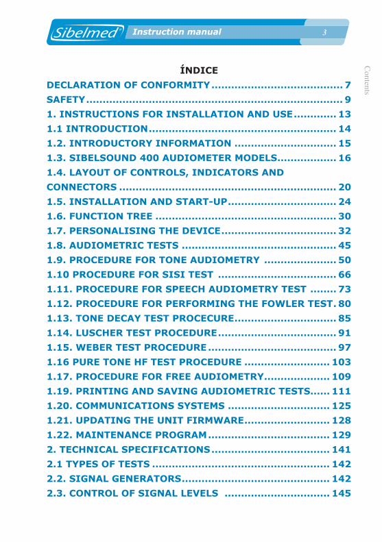
The sequence of operations to prepare the SIBELSOUND 400 to carry out audiometric tests is as follows:
1 Main power switch in position “0” OFF.
2 Connect the mains power cable to the device and to a 90V - 264V - 50 / 60Hz mains connection.
3 Connect the accessories to the corresponding connection points.
If all the previous instructions have been followed, the equipment is ready for use.
USB MODULE INSTALLATION
The equipment has an integrated Microcontroller for exclusive USB control, which is ready for use.To use with a computer, simply install the USB driver and the W50 Audiometry Software in the PC.To carry out these two installations, refer to the Instructions for Use for the W50 Audiometry Software.

2� Instruction manual
Cha
pter
1: I
nstru
ctio
ns fo
r Ins
talla
tion
and
Use
2� Instruction manual
RS MODULE INSTALLATION
The equipment has an optional module which enables communication between the audiometer and a computer over an RS232 connection. The instructions for installation are as follow:
With the audiometer disconnected from the mains, open the audiometer and connect the connectors J_RSP1 and J_RSP3 to the RS232 as shown in the diagram without forcing any of the pins. The module can only be connected in one position.

Chapter 1: Instructions for Installation and U
se
2� Instruction manual
INSTALLATION OF THE INTERCOM MODULE
The equipment has an optional module which allows communication to be established with the patient. The instructions for installation are as follow:
With the audiometer disconnected from the mains, open the audiometer and connect the connectors J_A9 and J_A10 to the intercom module as shown in the diagram without forcing any of the pins. The module can only be connected in one position.

2� Instruction manual
Cha
pter
1: I
nstru
ctio
ns fo
r Ins
talla
tion
and
Use
2� Instruction manual
START-UP
To start up the SIBELSOUND 400 audiometer, move the main power switch to position “I” ON. The following screen will appear for several seconds:
SIBELMEDSIBELSOUND 400
The equipment then performs a self-check in which it tests whether all the accessories are connected and whether the original calibration is correct. If the result is negative, it displays an alert showing which accessories are missing and/or the date of the most recent calibration. This calibration check assumes that the transducers, both for air conduction and bone conduction, are correct and have not suffered any deterioration. To prevent errors in this regard, we recommend performing a MINIMUM ANNUAL PERIODIC CALIBRATION, or when a malfunction is suspected, with an artificial ear and artificial mastoids.
Once the self-check has been completed, the audiometer automatically sets all the controls and indicators in accordance with the saved configuration (See section 1.7 PERSONALISING THE DEVICE).
NOTES ON THE HANDLING OF THE DEVICE
Ease of use has been a priority in the development of the audiometer, to make its use as easy and convenient for the user as possible. Given its multiple functions, the device may appear difficult to use. However, its design and actual use quickly reveal how easy and intuitive it is to use for anyone working in the health field.
All the functions are accessible by means of the keyboard following the instructions which appear on the screen (LCD).

Chapter 1: Instructions for Installation and U
se
2� Instruction manual
Both the keyboard and screen are located on the front panel of the device.
The screen consists of two lines of 16 alphanumeric characters each.
PrinterAll models can be connected, whether as a standard feature or an option, to an external printer, if this option has been selected previously in the Configuration. In this event, follow the instructions for the relevant printer.
AttenuatorsYou can change the channel which controls an attenuator. This allows you to control both channels with the same attenuator. To do so, press the relevant attenuator (the one you wish to take control) for 1 second. On effecting the change an indication appears (RIGHT <- / -> LEFT) for a few seconds, showing the new channel controlled by the particular attenuator.
This change is disabled in the following cases:
• On starting up the device
• When no key has been pressed for more than 5 minutes
• When the attenuator is pressed again for 1 second or more
• On carrying out a test with masking
Intercom (Optional) At any time, by holding down the key, it switches to the SPEECH channel (so that the patient receives the signal from the doctor's microphone) and the patient's microphone is activated so that the doctor can hear the patient.

�0 Instruction manual
Cha
pter
1: I
nstru
ctio
ns fo
r Ins
talla
tion
and
Use
�0 Instruction manual
The volume of the signal from the doctor and the sensitivity of the patient's microphone can be adjusted by operating the attenuators while holding down this key.
1.6. FUNCTION TREE
For a better understanding of the structure of the SIBELSOUND 400 audiometer we have included its function tree.
In general, it is possible to navigate through the various menu
options by means of the keys / or by rotating the attenuators The key selects the chosen option (similarly pressing the attenuators).
In the case of menus which allow several options to be selected (for example the Diagnosis menu), navigate through the options using the attenuators and select by
using the and keys, pressing to confirm. For menus which only allow selection of a single option which cancels all the others (for example, the Printer or Language menu), navigation is carried out with the attenuators and selection is made by pressing the key directly.
The key returns to the previous menu (if this key is held down for more than 1 seconds it returns to the Main Menu).
Not pressing any key for 60 seconds returns to the main screen.
When the device is turned on, the screen for the test which has been configured appears (default test is the Free test).
To access the menu with all functions press .
The Main Menu appears and, depending on the options, access, to:

Chapter 1: Instructions for Installation and U
se
�1 Instruction manual
THE SIBELSOUND 400 MENU (EXCEPT THE SUPRA MODEL)
1. TESTS 1. PURE TONE 2. SISI 3. SPEECH 4. FOWLER 5. TONE DECAY 6. LÜSCHER 7. WEBER 8. PURE TONE HF 9. FREE2. CONFIGURATION 1. SAVE CONFIGURATION 2. MODIFY DEFAULT 3. RESET DEFAULT 4. DIAGNOSIS 5. FREQUENCY 1 FREQ. SEL. 2 MUSICAL FREQ. 6. PRINTER 7. LANGUAGE 8. CONTRAST 9. DATE - TIME3. MAINTENANCE 1. TEST DEVICE 1. CPU 2. LCD 3. KEYBOARD 4. PRINTER 5. UPDATE KEY 6. VERSION 7. RESET DEVICE 2. CALIBRATION 1. ANSI / ISO 2. CALIBRATION WARNING 3. DEFAULT CALIBRATION 3. MONITOR 4. SPEECH-INTER 5. AUXILIARY4. DATABASE 1. VIEW 2. CLEAR DB 3. PATIENT SEARCH 4. PATIENT DELETE5. REFERENCE TONE6. AUTO MASK

�2 Instruction manual
Cha
pter
1: I
nstru
ctio
ns fo
r Ins
talla
tion
and
Use
�2 Instruction manual
The various options can also be accessed directly. To do this
just press the key and enter the numerical sequence of the various menus you would navigate through to access the required option. For example, to carry out the keyboard test you would need to press: (Menu), 3 (Maintenance), 1 (Test Device) and 3 (Keyboard).
1.7. PERSONALISING THE DEVICE
Any equipment with complex functionality may be modified voluntarily or otherwise by third parties to change the default configuration of its controls, affecting convenience of use.To prevent against this anomaly, the SIBELSOUND 400 audiometer has a configuration program which allows a user to define their initial work configuration and reload it every time they turn the device on.
This information is saved in internal Flash memory so that it does not disappear when the device is turned off.
On turning the device on for the first time, the two configurations are the same. The configuration which is loaded at the start is the user's.The sub-section INITIAL CONFIGURATION explains the procedure for selecting a particular initial configuration.
The options which can be configured are:• Diagnosis• Frequencies• Printer• Contrast• Language• Calibration• Inicial test• Parameters for each of the various test• Date-Time• Auto-mask• High Frequency in the Free test.

Chapter 1: Instructions for Installation and U
se
�� Instruction manual
PERSONALISING DIAGNOSIS
Take the following steps to select the type of diagnosis that will appear in the report:
1 From the Main Menu access the option
MENU2. CONFIGURATION
2 Select
CONFIGURATION4. DIAGNOSIS
3 Choose the diagnosis you require from the following:
1. Ministry of Labour and Social Affairs 2. Council of Physical Therapy 3. Mexican Social Security Institute 4. ELI Index 5. SAL Index 6. Klockhoff Index

�� Instruction manual
Cha
pter
1: I
nstru
ctio
ns fo
r Ins
talla
tion
and
Use
�� Instruction manual
PERSONALISING FREQUENCIES
To select the frequencies for inspection in the Pure Tone and Free tests:
1 From the Main Menu access the option
MENU2. CONFIGURATION
CONFIGURATION5. FREQUENCY
FREQUENCY 1. FREQ. SEL.
2 Select
CONFIGURATION5. SEL. FREQ
3 Choose the desired frequencies.
CUSTOMISING MUSICAL FREQUENCIES
To select the musical frequencies in the Pure Tone and Free tests:
1 From the main menu, access the following option
MENU2. CONFIGURATION

Chapter 1: Instructions for Installation and U
se
�� Instruction manual
2 Select
CONFIGURATION5. FREQUENCY
FREQUENCY 1. MUSICAL FREQ.
3 Use the attenuators to choose whether or not you want to use musical frequencies and press “ENTER”.
FREQUENCYMus. Freq. ON(*)
The musical frequencies appear on the chart below and correspond to traditional frequencies when shown on the screen or on reports:
MUSICAL
FREQUENCY (Hz)CONVENTIONAL FREQUENCY (Hz)
130.8 125
261.6 250
523.3 500
1046.5 1000
2093.0 2000
4186.0 4000
8372.0 8000
If the musical frequencies have been selected, they are shown on the Pure Tone and Free test screen of the threshold review and the database with an asterisk next to the value of the frequency. They are indicated in the reports with the warning: “Attention: Musical frequencies”, underneath the Pure Tone test graphs.
Example of a Pure Tone test screen with the Musical Frequencies
�� Instruction manual
Cha
pter
1: I
nstru
ctio
ns fo
r Ins
talla
tion
and
Use
�� Instruction manual
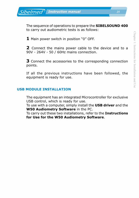
option selected:
A HZ C A HZ C60 1000* 60
PERSONALISING PRINTING
To select the printer:
1 From the Main Menu access the option
MENU2. CONFIGURATION
2 Select
CONFIGURATION6. PRINTER
3 Choose the printer you wish to use
PERSONALISING LANGUAGE
To personalise language:
1 From the Main Menu access the option
MENU2. CONFIGURATION
2 Select
MENU7. LANGUAGE
Chapter 1: Instructions for Installation and U
se
�� Instruction manual
3 Choose the required language.
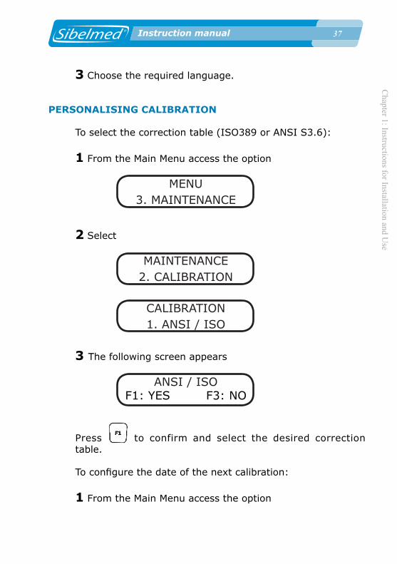
PERSONALISING CALIBRATION
To select the correction table (ISO389 or ANSI S3.6):
1 From the Main Menu access the option
MENU3. MAINTENANCE
2 Select
MAINTENANCE2. CALIBRATION
CALIBRATION1. ANSI / ISO
3 The following screen appears
ANSI / ISOF1: YES F3: NO
Press to confirm and select the desired correction table.
To configure the date of the next calibration:
1 From the Main Menu access the option

�� Instruction manual
Cha
pter
1: I
nstru
ctio
ns fo
r Ins
talla
tion
and
Use
�� Instruction manual
MENU3. MAINTENANCE
2 Select
MAINTENANCE2. CALIBRATION
CALIBRATION2. CAL. WARNING
3 The following screen appears
Last Calibration01-05-08
With the date of the last calibration.
Press
4 The following screen appears
Maint. IntervalDays: 365
Enter the number of days until the next calibration is to take place. On the specified date, a warning message will appear reminding you to calibrate the device.

Chapter 1: Instructions for Installation and U
se
�� Instruction manual
WARNINGIt is not advisable to change the date once it has been programmed with the appropriate interval so that the device will always be correctly calibrated.
RECOVERING THE DEFAULT CALIBRATION
To recover the default calibration:
1 From the Main Menu access the option
MENU3. MAINTENANCE
2 Select
MAINTENANCE2. CALIBRATION
CALIBRATION3. DEFAULT CAL
3 The following screen appears
DEFAULT CALF1: YES F3: NO
Press to recover the default calibration.

�0 Instruction manual
Cha
pter
1: I
nstru
ctio
ns fo
r Ins
talla
tion
and
Use
�0 Instruction manual
WARNING:PRESSING F1 WILL DELETE THE WORKING CALIBRATION OF THE UNIT, WHICH IS SPECIFIC FOR EACH AUDIOMETER. THE DEFAULT CALIBRATION WILL BE USED INSTEAD, WHICH IS GENERIC FOR ALL THE UNITS.
PERSONALISING CONTRAST
To personalise screen contrast:
1 From the Main Menu access the option
MENU2. CONFIGURATION
2 Select
CONFIGURATION8. CONTRAST
3 Choose the required contrast.
PERSONALISATION OF DATE AND TIME
To configure the device date and time:
1 From the Main Menu access the option
MENU2. CONFIGURATION
2 Select
CONFIGURATION9. DATE - TIME
Chapter 1: Instructions for Installation and U
se
�1 Instruction manual
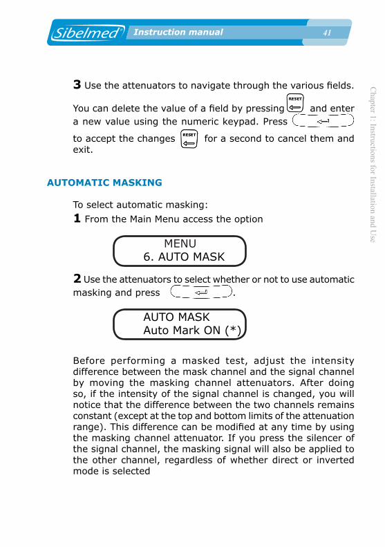
3 Use the attenuators to navigate through the various fields.
You can delete the value of a field by pressing and enter a new value using the numeric keypad. Press
to accept the changes for a second to cancel them and exit.
AUTOMATIC MASKING
To select automatic masking:
1 From the Main Menu access the option
MENU6. AUTO MASK
2 Use the attenuators to select whether or not to use automatic masking and press .
AUTO MASKAuto Mark ON (*)
Before performing a masked test, adjust the intensity difference between the mask channel and the signal channel by moving the masking channel attenuators. After doing so, if the intensity of the signal channel is changed, you will notice that the difference between the two channels remains constant (except at the top and bottom limits of the attenuation range). This difference can be modified at any time by using the masking channel attenuator. If you press the silencer of the signal channel, the masking signal will also be applied to the other channel, regardless of whether direct or inverted mode is selected

�2 Instruction manual
Cha
pter
1: I
nstru
ctio
ns fo
r Ins
talla
tion
and
Use
�2 Instruction manual
HIGH FREQUENCY
This option allows to realize a Free test by Air HF conduction in the range from 125 to 20.000 Hz. To select the high frequency option:
1 From the Main Menu, select the Free test
MENU1. TEST
MENU9. FREEE
2 Press simultaneously + o+ keys.
3 Use the attenuators to choose whether or not you want to enable the High Frequency option and press .
HIGH FREQHigh Freq ON (*)
INITIAL CONFIGURATION
The process to specify the initial working configuration is as follows:
1 Set the controls to the positions which you would like them to be in when the audiometer is turned on.
2 Access each of the tests and select: the values for the attenuators, the conduction route, the mode, the source and the frequency.
Chapter 1: Instructions for Installation and U
se
�� Instruction manual
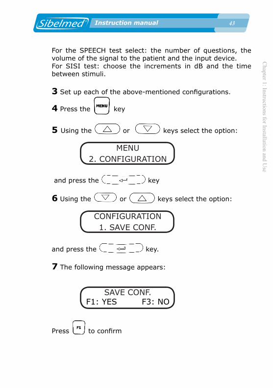
For the SPEECH test select: the number of questions, the volume of the signal to the patient and the input device. For SISI test: choose the increments in dB and the time between stimuli.
3 Set up each of the above-mentioned configurations.
4 Press the key
5 Using the or keys select the option:
MENU2. CONFIGURATION
and press the key
6 Using the or keys select the option:
CONFIGURATION1. SAVE CONF.
and press the key.
7 The following message appears:
SAVE CONF.F1: YES F3: NO
Press to confirm

�� Instruction manual
Cha
pter
1: I
nstru
ctio
ns fo
r Ins
talla
tion
and
Use
�� Instruction manual
SAVE CONF.CONF. SAVED
Once this has been done, the audiometer will set itself in the selected position each time it is turned on.
The only function it cannot memorise is the "silencer" function for each channel.
These always remain in the "direct" position (no signal is applied unless the relevant keys are pressed).
DEFAULT CONFIGURATION
To modify the default configuration:
1 From the Main Menu access the option
MENU2. CONFIGURATION
2 Select
CONFIGURATION2. MODIF DEFAULT
3 The following message appears:
MODIF. DEFAULTF1: YES F3: NO
Press to confirm

Chapter 1: Instructions for Installation and U
se
�� Instruction manual
MODIF. DEFAULTDEFAULT CHANGED
To copy the default configuration to the user's configuration:
1 From the Main Menu access the option
MENU2. CONFIGURATION
2 Select
CONFIGURATION3. RESET DEFAULT
3 The following message appears:
RESET DEFAULTF1: YES F3: NO
Press to confirm
RESET DEFAULTDEFAULT RESET
1.8. AUDIOMETRIC TESTS
The SIBELSOUND 400 audiometer supports many types of audiometric investigations.

�� Instruction manual
Cha
pter
1: I
nstru
ctio
ns fo
r Ins
talla
tion
and
Use
�� Instruction manual
For ease of use, the Main Menu allows you to access the various tests and, if you wish, prepare the printed report automatically. This does not prevent the user from setting up the report manually or carrying out many other tests using the FREE AUDIOMETRY option.
To carry out a test, push the key:
MENU1. TESTS
press the key, and choose the TEST you require: 1. PURE TONE (Tone Audiometry) 2. SISI (SISI test) 3. SPEECH (Speech audiometry) 4. FOWLER 5. TONE DECAY 6. LUSCHER 7. WEBER 8. PURE TONE HF (Pure tone high frequency audiometry) 9. FREE (Free audiometry)
This manual explains the mechanism for carrying out various audiometric investigations. This is not the only possible mechanism and must therefore be adapted to the criteria which the specialist regards as most appropriate in each case.
These tests include other variants that are not included. The procedures for the latter fall to the specialist to determine.For anyone not familiar with these techniques, we recommend reference to relevant literature.
A brief description of each of the tests displayed on the OPTIONS MENU is shown below.

Chapter 1: Instructions for Installation and U
se
�� Instruction manual
TONE AUDIOMETRY
Tone audiometry is the basic test which involves the determination of threshold hearing levels via air and bone conduction, with or without NBN masking.Free-field audiometry is carried out in a similar way to tone audiometry via air conduction.This test can be carried out using air conduction with any SIBELSOUND 400 model. Free-field tests, via bone conduction and masking are only integrated in some models and are optional in others.
SISI TEST
SISI (Short Increment Sensitivity Index following Jerger). This consists of increments in a continuous pure tone of 1dB with rise time of 50 ms, duration of 200 ms and fall of 50 ms. The stimulus may be applied manually or automatically.It is provided as standard with the SIBELSOUND 400 AOM+, SUPRA model, and in other models if incorporated as an option.
SPEECH AUDIOMETRY
Speech audiometry essentially consists of determining the threshold of intelligibility (the patient hears and understands words pronounced) using a list of words spoken live or via recorded material.
Speech audiometry has many variants not addressed in this manual, which are left to specialist criteria.
It can be carried out with the SIBELSOUND 400 AOM+, SUPRA and SUPRA models, and other models if incorporated as an option.
FOWLER
�� Instruction manual
Cha
pter
1: I
nstru
ctio
ns fo
r Ins
talla
tion
and
Use
�� Instruction manual
The Fowler test is used to verify the balance between the two ears. This involves comparing equal sound intensity between the two ears at the same frequency. This is aimed more at predominantly unilateral deafness: the two ears must not be identical. This test is performed to ascertain whether recruitment occurs when the hearing threshold is normal or less than 30 dB and the other ear shows a hearing loss of 25 to 60 dB. It is also called ABLB (Alternate Binaural Loudness Balance).
It is performed with the SIBELSOUND 400 SUPRA model and also with the other models if this option is included.
TONE DECAY
The Tone Decay test involves exposing the patient to a pure tone at 5 dB above the hearing threshold and observing whether it is perceived clearly for 60 seconds. Normally it would be perceived throughout this period. If not, the level is increased in 5 dB steps until it can again be heard and again successively until the patient confirms he can hear the sound for one minute.
It is performed with the SIBELSOUND 400 SUPRA model and also with the other models if this option is included.
LUSCHER
The Luscher test consists in distinguishing between signal modulation variations. For the ear to perceive an increase or decrease in physical intensity due to a change in subjective intensity (sonority), the physical intensity must change by more than a certain value. This small change in physical intensity perceived by the ear is called the differential threshold. This is done by applying a modulated tone with a band width of 40 dB above the threshold and ascertaining the modulation threshold
Chapter 1: Instructions for Installation and U
se
�� Instruction manual
at which the subject ceases to hear or begins to hear the tone modulation, depending on whether the level rises or falls.
It is performed with the SIBELSOUND 400 SUPRA model and also with the other models if this option is included.
WEBER
The Weber test consists in investigating all frequencies between 250 and 4000 Hz, at 15 dB above the subject's forehead bone threshold. The vibrator is applied to the forehead and it is held in place with a headband and not by hand, as this could influence the pressure and lead to error. A note is made of which side the patient perceives the sound to be coming from. This test is fundamental in clinical audiometry; its physiopathological significance is considered subsequently, for purposes of diagnosing deafness.
It is performed with the SIBELSOUND 400 SUPRA model and also with the other models if this option is included.
PURE TONE HF
Pure Tone HF audiometry is basically a pure tone audiometry in which the frequency range wide up to 20.000 Hz and is applied by the air HF conduction. It also allows to realize masking with narrow band noise and white noise sources.
It’s an option in the SIBELSOUND 400 AOM, AOM+ and SUPRA models.
FREE AUDIOMETRY
This audiometer option MUST NOT BE CONFUSED WITH FREE FIELD.By selecting "Free Audiometry" the user can carry out any other test with the audiometer, including those described above, as the audiometer permits access to and selection of all of its functions, even though some may appear absurd.

�0 Instruction manual
Cha
pter
1: I
nstru
ctio
ns fo
r Ins
talla
tion
and
Use
�0 Instruction manual
In the tests described earlier, the device software blocks certain functions which are not normally relevant to the test being carried out and therefore variants are not possible. With the "FREE AUDIOMETRY" option, there is access to the full range of capabilities of the equipment.
It is available with all models.
With this option it is not possible to produce reports or save tests in the database.
1.9. PROCEDURE FOR TONE AUDIOMETRY
GENERAL CONSIDERATIONS
TechnicianThe technician performing the test must be trained in the theory and practice of audiometric testing, since they will have to take decisions such as:
• Which ear to test first? (Usually the one the patient thinks has the better hearing function)
• Is masking required or not?
• When does the patient's response match the signal? (The SIBELSOUND 400 gives warning of inconsistencies)
• Is there some external noise or patient response which could invalidate the test?• In the event of an interruption, should the test be repeated or continued?, etc.
Test durationPatient exhaustion should be avoided, as it can be difficult to obtain results if the test lasts longer than 20 minutes and the patient is not allowed any rest time.

Chapter 1: Instructions for Installation and U
se
�1 Instruction manual
Ambient ConditionsWe recommend installing the audiometer together with a soundproof booth for audiometric tests. If this is not possible, the equipment must be installed in an area where the level of ambient noise is low enough not to distort the results of audiometric tests. Failing that, SOUND SUPPRESSORS can be used in the headphones (OPTIONAL).
PATIENT REPARATION AND INSTRUCTIONS
Patient preparationRecent exposure on the part of the patient to elevated noise levels could cause a temporary increase in hearing thresholds. Therefore, high noise levels should be avoided before the test or this should be indicated on the report. To avoid errors due to physical effort, we recommend that the patient be at the location of the test at least five minutes before it takes place.An otoscopic examination is usually carried out by a qualified person, to establish whether there is an obstruction in the external ear canal that needs to be removed.It is vital that the patient is comfortably seated, calm and rested so they can give maximum attention to the test.
Patient instructionsThe technician carrying out the test must explain to the patient what it involves, and also the following:
• The patient response is effected by pressing the patient's response button.
• The patient must respond when they hear the tone, not when they think they hear it.
• Response must begin the moment they hear the tone and cease immediately after they cease to hear it.
• The general sequence of the presentation of tones.

�2 Instruction manual
Cha
pter
1: I
nstru
ctio
ns fo
r Ins
talla
tion
and
Use
�2 Instruction manual
• Which ear will be tested first. Putting on the headphones
Glasses and jewellery need to be removed when they prevent correct positioning of headphones for air or bone conduction. Similarly, check that hair does not impede the connection between the transducers and the outer ear or mastoids.The technician must place the air conduction headphones on the patient, checking that they fit correctly, and following the convention "RIGHT ear" = RED and "LEFT ear" = BLUE.
PREPARING THE AUDIOMETER
Before explaining the procedure for performing the test, it is convenient to present the characters which may appear on the screen. These show the operational status of the device at all times. As mentioned previously, the screen consists of two lines of 16 alphanumeric characters each.
On the first line, the characters located in positions 0 to 7 refer to the right channel and those located at positions 8 to 15 to the left channel.
The characters which can appear in each of the positions on the screen when a test is being carried out are described below.
ABCDEFGHIJKLMNOPABCDEFGHIJKLMNOP
On the first line:
A and J Route of application (A Air Conduction/ O Bone
Conduction / - Disable).
Select with + left or right attenuator according to channel.

Chapter 1: Instructions for Installation and U
se
�� Instruction manual
CDE and LMN Signal source (HZ Frequency of Pure Tone in Hz / NBN Masking with Narrow Band Noise / WN White Noise)
Select with + left or right attenuator according to channel.
G and P Mode of presentation of the signal (C Continuous signal / P Pulsating signal)
Select with + left or right attenuator according to channel.On the second line:
ABC and NOP Signal level applied to the patient in "dB" ABC right channel. Select with right attenuator.NOP left channel. Select with left attenuator. DE and LM Two cursors that indicate that a signal is being applied to the patient.
DE right channel. Apply signal with
LM left channel. Apply signal with
FGHIJ Frequency in Hz of the tone appliedSelect with /
With the audiometer prepared as indicated in section 1.5. INSTALLATION AND START-UP, proceed as follows:
1 Press the key.
Using the and keys select the option:
�� Instruction manual
Cha
pter
1: I
nstru
ctio
ns fo
r Ins
talla
tion
and
Use
�� Instruction manual
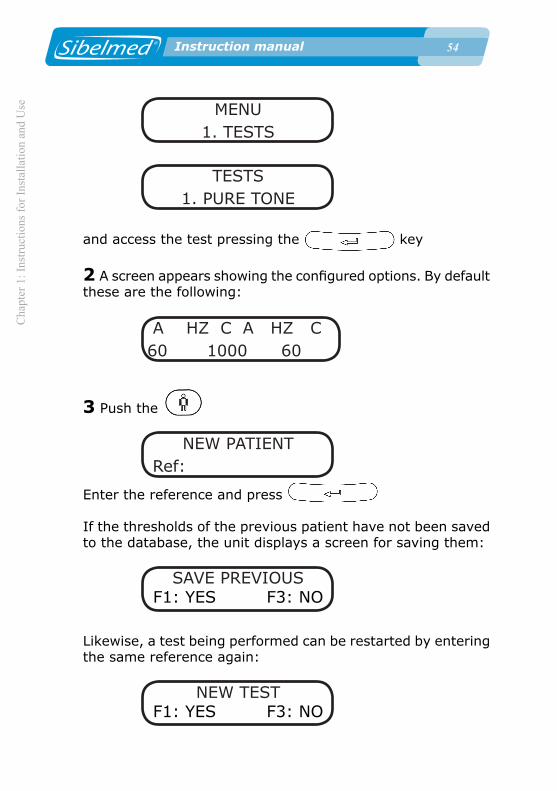
MENU1. TESTS
TESTS1. PURE TONE
and access the test pressing the key
2 A screen appears showing the configured options. By default these are the following:
A HZ C A HZ C 60 1000 60
3 Push the
NEW PATIENT Ref:
Enter the reference and press
If the thresholds of the previous patient have not been saved to the database, the unit displays a screen for saving them:
SAVE PREVIOUSF1: YES F3: NO
Likewise, a test being performed can be restarted by entering the same reference again:
NEW TESTF1: YES F3: NO

Chapter 1: Instructions for Installation and U
se
�� Instruction manual
Select to delete all the thresholds saved for the current test and start the test again.
NOTE: When ELI diagnosis is selected, after the previous
screen the following appear:
NEW PATIENT
Age: NEW PATIENT
Sex: Man
4 Press
A HZ C A HZ C AIR AIR
Using the corresponding attenuator, select the route of application of the signal for each channel: air (A), bone (O), free field (F) or disabled (-).
5 Press
A HZ C A HZ C TONE TONE
Using the corresponding attenuator, select the source of the signal for each channel: frequency of pure tone in Hz (HZ) , masking with narrow band noise(NBN) or masking with white noise(WN).
6 Press

�� Instruction manual
Cha
pter
1: I
nstru
ctio
ns fo
r Ins
talla
tion
and
Use
�� Instruction manual
A HZ C A HZ C CONTIN. CONTIN.
Using the corresponding attenuator, select the mode of presentation of the signal for each channel: continuous signal (C) or pulsating signal (P).
7 Choose the intensity of the signal by rotating the attenuators until the required value is found.
A HZ C A HZ C 60 1000 60
8 Select the frequency of the signal (press or
until the required value is found)
A HZ C A HZ C 60 1000 60
• To apply the signal to the patient press the or
keys, depending on the channel on which you wish to apply it.
WARNING:THIS DEVICE IS PROVIDED WITH A PROTECTION SYSTEM THAT PROTECTS THE TDH39 AERIAL HEADPHONES FROM SIGNALS THAT ARE TOO HIGH DURING PROLONGED PERIODS OF TIME. AS A RESULT, AT CERTAIN FREQUENCIES THE SIGNAL DEACTIVATES AUTOMATICALLY AFTER A FEW SECONDS AT MORE THAN 100 DB.The signal indicator looks like this
Chapter 1: Instructions for Installation and U
se
�� Instruction manual
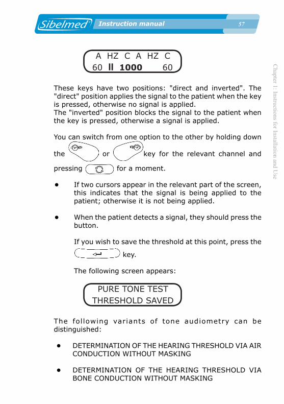
A HZ C A HZ C 60 II 1000 60
These keys have two positions: "direct and inverted". The "direct" position applies the signal to the patient when the key is pressed, otherwise no signal is applied. The "inverted" position blocks the signal to the patient when the key is pressed, otherwise a signal is applied.
You can switch from one option to the other by holding down
the or key for the relevant channel and
pressing for a moment.
• If two cursors appear in the relevant part of the screen, this indicates that the signal is being applied to the patient; otherwise it is not being applied.
• When the patient detects a signal, they should press the button.
If you wish to save the threshold at this point, press the
key.
The following screen appears:
PURE TONE TESTTHRESHOLD SAVED
The following variants of tone audiometry can be distinguished:
• DETERMINATION OF THE HEARING THRESHOLD VIA AIR CONDUCTION WITHOUT MASKING
• DETERMINATION OF THE HEARING THRESHOLD VIA BONE CONDUCTION WITHOUT MASKING
�� Instruction manual
Cha
pter
1: I
nstru
ctio
ns fo
r Ins
talla
tion
and
Use
�� Instruction manual
• DETERMINATION OF THE HEARING THRESHOLD VIA AIR CONDUCTION WITH MASKING
• DETERMINATION OF THE HEARING THRESHOLD VIA BONE CONDUCTION WITH MASKING
• SCREENING AUDIOMETRY As explained earlier, this manual explains the mechanism
for carrying out various audiometric investigations. This is not the only possible mechanism and must therefore be adapted to the criteria which the specialist regards as most appropriate in each case.
A description of each type of tone audiometry in accordance with standard ISO 8253-1, is shown below
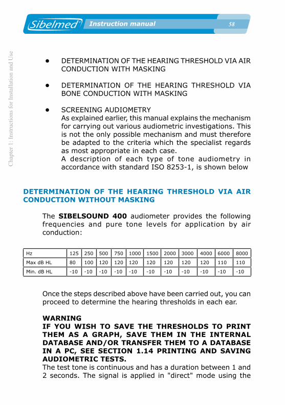
DETERMINATION OF THE HEARING THRESHOLD VIA AIR CONDUCTION WITHOUT MASKING
The SIBELSOUND 400 audiometer provides the following frequencies and pure tone levels for application by air conduction:
Hz 125 250 500 750 1000 1500 2000 3000 4000 6000 8000
Max dB HL 80 100 120 120 120 120 120 120 120 110 110
Min. dB HL -10 -10 -10 -10 -10 -10 -10 -10 -10 -10 -10
Once the steps described above have been carried out, you can proceed to determine the hearing thresholds in each ear.
WARNINGIF YOU WISH TO SAVE THE THRESHOLDS TO PRINT THEM AS A GRAPH, SAVE THEM IN THE INTERNAL DATABASE AND/OR TRANSFER THEM TO A DATABASE IN A PC, SEE SECTION 1.14 PRINTING AND SAVING AUDIOMETRIC TESTS.The test tone is continuous and has a duration between 1 and 2 seconds. The signal is applied in "direct" mode using the

Chapter 1: Instructions for Installation and U
se
�� Instruction manual
or keys. When there is a patient response, the interval between the sounding of the tone varies but is never shorter than the duration of the tone.
NOTE:When the patient presses the response button, the response is displayed on the screen and the decibel level of the signal applied is shown blinking.If the patient presses the button in the absence of a signal, the message “NO SIGNAL” appears on the screen.
It is advisable to carry out a training test first to familiarise the patient with the procedure. This is done as follows:
• Apply a 1000 Hz (frequency) tone using or
.
• Use a level which is clearly audible (for example an intensity of 40 dB, for a normal subject), rotating the attenuators until this value is found.
• Reduce the level in 20 dB steps until the subject can no longer hear it.
• Increase the level until they can again hear it.
• Sound the tone again at the same level.
If the patient responds consistently, they are appropriately familiarised. If not, repeat the process.
The steps to take to determine the hearing thresholds are as follow:
1 The order of sounding of pure tones is: 1000, 1500, 2000, 3000, 4000, 6000, 8000, 750, 500, 250 and 125 Hz.Some of these frequencies can be omitted, depending on the specialist's criteria.

�0 Instruction manual
Cha
pter
1: I
nstru
ctio
ns fo
r Ins
talla
tion
and
Use
�0 Instruction manual
2 Sound the test tone at a level 10 dB below the threshold detected during training. Carry on increasing the level in 5 dB steps until there is a response from the patient.
3 Following the response, reduce the level in 10 dB steps until there ceases to be a response and then start to increase it again (new "ascent"). Continue the process until there have been three responses at the same level within a maximum of five ascents (auditory responses within three ascents, abbreviated method). If less than three responses are detected in five ascents (or less than two responses in three ascents), switch to a tone with a level 10 dB higher than the level of the previous response and repeat the process.
4 On the graph of the ear being tested, write down the hearing threshold level which corresponds to the lowest level at which the number of patient responses exceeds half the number of ascents.
Note:If the lowest response levels for a particular frequency differ by more than 10 dB, the threshold hearing level should be regarded as dubious and it is advisable to repeat the process.If there is a difference greater than or equal to 15 dB between two correlative frequencies, the audiometry can be considered doubtful, unless this represents a sustained gradient along the curve. In the event of neurosensory hypoacusia with a serious loss of high frequencies, there tends to be more than 15 dB between two correlative frequencies, but the whole curve exhibits that gradient.
5 Repeat steps 2, 3 and 4 for the next frequency.
An audiometric file output via a printer is shown at the end of this chapter.

Chapter 1: Instructions for Installation and U
se
�1 Instruction manual
DETERMINATION OF THE HEARING THRESHOLD VIA AIR CONDUCTION WITH MASKING
To avoid the test tone being heard by the ear other than the one being tested, it is necessary to apply a masking noise to that ear.
The SIBELSOUND 400 audiometer provides Narrow Band Noise NBN with the following levels of masking in each of the frequencies for application via air conduction:
Hz 125 250 500 750 1000 1500 2000 3000 4000 6000 8000
Max dB HL 60 80 100 100 100 100 100 100 100 100 90
Min. dB HL -10 -10 -10 -10 -10 -10 -10 -10 -10 -10 -10
Although experience largely dictates the process and level of noise to apply, a recommended method for determining hearing thresholds with masking is presented below.
1 Apply a test tone to the ear being tested with a level equal to the hearing threshold without masking. Select narrow band noise NBN in the other audiometer channel and apply a level of effective masking to the other ear that is equal to the hearing threshold level of the latter. Increase the level of masking until the test zone is inaudible or until it exceeds the level of the test tone.
2 If the test tone is still audible when the level of noise is equal to the level of the tone, this is taken as the hearing threshold. If the test tone remains masked, the level of the latter is increased until it is audible once again.
3 Increment the noise level in 5 dB steps. If the test tone is inaudible, increase the level until it is audible once again. Repeat this process until the test tone remains audible even
�2 Instruction manual
Cha
pter
1: I
nstru
ctio
ns fo
r Ins
talla
tion
and
Use
�2 Instruction manual
though the level of masking noise has been increased by more than 10 dB. This level of masking (which is the level from which no subsequent increase in the level of tone was required to make it audible) is the correct level and this process should have resulted in the correct hearing threshold for the test frequency. Make a note of the correct level of masking.
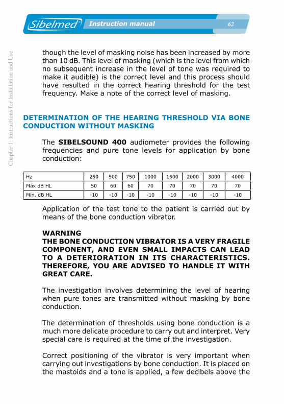
DETERMINATION OF THE HEARING THRESHOLD VIA BONE CONDUCTION WITHOUT MASKING
The SIBELSOUND 400 audiometer provides the following frequencies and pure tone levels for application by bone conduction:
Hz 250 500 750 1000 1500 2000 3000 4000
Máx dB HL 50 60 60 70 70 70 70 70
Mín. dB HL -10 -10 -10 -10 -10 -10 -10 -10
Application of the test tone to the patient is carried out by means of the bone conduction vibrator.
WARNINGTHE BONE CONDUCTION VIBRATOR IS A VERY FRAGILE COMPONENT, AND EVEN SMALL IMPACTS CAN LEAD TO A DETERIORATION IN ITS CHARACTERISTICS. THEREFORE, YOU ARE ADVISED TO HANDLE IT WITH GREAT CARE.
The investigation involves determining the level of hearing when pure tones are transmitted without masking by bone conduction.
The determination of thresholds using bone conduction is a much more delicate procedure to carry out and interpret. Very special care is required at the time of the investigation.
Correct positioning of the vibrator is very important when carrying out investigations by bone conduction. It is placed on the mastoids and a tone is applied, a few decibels above the
Chapter 1: Instructions for Installation and U
se
�� Instruction manual
hearing threshold, and the patient is asked to move it around the mastoids until they find the area that maximises the volume of the tone. Make sure that the vibrator is perfectly attached to the mastoids and is not in contact with the external part of the year so as to avoid conduction through the cartilage.When determining thresholds using bone conduction without masking, the opposite ear must be completely unobstructed, that is, must not be covered by a headset for air conduction or by any other object which might alter the results of the test. When this is not the case, it must be indicated.
With the exception of the indications mentioned above, the determination of thresholds using bone conduction must be carried out as described in the previous section DETERMINATION OF THE HEARING THRESHOLD VIA AIR CONDUCTION WITHOUT MASKING.
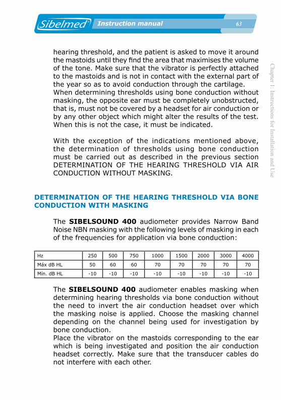
DETERMINATION OF THE HEARING THRESHOLD VIA BONE CONDUCTION WITH MASKING
The SIBELSOUND 400 audiometer provides Narrow Band Noise NBN masking with the following levels of masking in each of the frequencies for application via bone conduction:
Hz 250 500 750 1000 1500 2000 3000 4000
Máx dB HL 50 60 60 70 70 70 70 70
Mín. dB HL -10 -10 -10 -10 -10 -10 -10 -10
The SIBELSOUND 400 audiometer enables masking when determining hearing thresholds via bone conduction without the need to invert the air conduction headset over which the masking noise is applied. Choose the masking channel depending on the channel being used for investigation by bone conduction.Place the vibrator on the mastoids corresponding to the ear which is being investigated and position the air conduction headset correctly. Make sure that the transducer cables do not interfere with each other.

�� Instruction manual
Cha
pter
1: I
nstru
ctio
ns fo
r Ins
talla
tion
and
Use
�� Instruction manual
For the purposes of this explanation, assume that the investigation of thresholds will begin with the right ear.Although experience largely dictates the process and level of noise to apply, a recommended method for determining hearing thresholds via bone conduction with masking is described below.
1 Apply a test tone to the ear being investigated at a level equal to the hearing threshold via bone conduction without masking. Select narrow band noise NBN with the other audiometer channel and apply a level of effective masking to the other ear equal to the threshold hearing level via air conduction for the latter. Increase the level of masking until the test tone is inaudible or until it exceeds the level of the test tone by 40 dB.
2 If the test tone is still audible when the noise level is 40 dB higher than the test tone, this is taken as the hearing threshold. If the test tone remains masked, the level of the latter is increased until it is audible once again.
3 Increment the noise level in 5 dB steps. If the test tone is inaudible, increase the level until it is audible once again. Repeat this process until the test tone remains audible even though the level of masking noise has been increased by more than 10 dB. This level of masking (which is the level from which no subsequent increase in the level of tone was required to make it audible) is the correct level and this process should have resulted in the correct hearing threshold for the test frequency. Make a note of the correct level of masking.
SCREENING AUDIOMETRY
This type of test is used in cases where the objective is to establish whether or not the subject can hear certain levels, rather than to determine hearing thresholds. It is a simple and quick method.
Screening audiometry is a test that determines if a subject has

Chapter 1: Instructions for Installation and U
se
�� Instruction manual
a hearing threshold better, equal to or worse than a determined screening level. The screening level is left to the discretion of a specialist.Screening audiometry can then be completed by determining the hearing threshold for those frequencies where the subject failed the screening test. In this case, the procedure for determining thresholds is as described in the section DETERMINATION OF THE HEARING THRESHOLD VIA AIR CONDUCTION WITHOUT MASKING .
The general aspects and the preparation for and instructions to the patient are as described at the beginning of that section.
To carry out the test follow the procedure described below:
1 Select each channel with the following screen display:
A HZ C - HZ C 40 1000 40
For the purposes of this explanation, assume that the investigation will begin with the right ear.
2 Select the frequency and the screening level. The order of application of pure tone frequencies is: 1000, 2000, 4000, 6000, 8000, 500 and 250 Hz. Some of these frequencies may be omitted or others added from the range the audiometer has available, at the discretion of the specialist.
3 First apply a 1000 Hz tone to the subject's right ear at a signal level of 40 dB to check whether the subject has understood the instructions.If not, the instructions are given again and the tone repeated. If the subject does not respond, increase the level of the tone until there is a response.
4 Adjust the signal level to be applied to match the screening level and present two tones with duration of 1 and 2 seconds

�� Instruction manual
Cha
pter
1: I
nstru
ctio
ns fo
r Ins
talla
tion
and
Use
�� Instruction manual
and an interval between each tone of 3 to 5 seconds. If the subject detects both tones, they have passed the test at this frequency. If only one tone was heard, present another tone. If the third tone has been detected, the subject has passed the test at this frequency. If the third tone or the first two tones were not heard by the subject, they have not passed the screening test at this frequency.
5 Select another frequency and repeat point 4.
6 Once the right ear has been tested, repeat the process described in points 4 and 5, blocking the right channel signal and activating the left, according to
- HZ C A HZ C 40 1000 40
(The dB level specified is a guideline)
1.10 PROCEDURE FOR SISI TEST
The general aspects and the preparation for and instructions to the patient are as described at the beginning of section 1.9. PROCEDURE FOR TONE AUDIOMETRY.
Before explaining the procedure for performing the test, it is convenient to present the characters which may appear on the screen. These show the operational status of the device at all times.
A Rxx S A Sxx SABCDEFGHIJKLMNOP
As mentioned previously, the screen consists of two lines of 16 alphanumeric characters each.

Chapter 1: Instructions for Installation and U
se
�� Instruction manual
On the first line, the characters located in positions 0 to 7 refer to the right channel and those located at positions 8 to 15 to the left channel.
In this test the signal source to be used is a Pure Tone in Hz.
The characters which can appear in each of the positions on the screen when a test is being carried out are described below.
On the first line:
A Route of application (A Air Conduction / - Disabled)
Select with + left or right attenuator according to channel.
S Mode of presentation of the signal (S Sisi-test / - Disabled)
Select with + left or right attenuator according to channel (only one channel can be activated).
Sxx Counter for the number of stimulus (signal increases) applied to the patient (From E00 to E20) Rxx Counter for the number of correct responses from the patient (the patient presses the button after the stimulus has been applied)
On the second line:
ABC and NOP Signal level applied to the patient in "dB" ABC right channel. Select with right attenuator.NOP left channel. Select with left attenuator. DE and LM Arrow which indicates that a signal is being applied to the patient.

�� Instruction manual
Cha
pter
1: I
nstru
ctio
ns fo
r Ins
talla
tion
and
Use
�� Instruction manual
DE right channel. Apply signal with .
LE left channel. Apply signal with .
FGHIJ Frequency in Hz of the tone applied
Select with / .
On pressing the key :
EFG Intensity of the increases in signal (From 0,2 to 5 dB). Select with right attenuator.
NOP Spacing between applications of the signal (MAN: Manual / 1- 9 seconds: automatic).
Select with left attenuator.
The SISI (Short Increment Sensitivity Index) test measures the ear's ability to detect small increases in intensity.
The test involves the application of 1 dB increments to a continuous tone with a rise time of 50 ms, duration of 200 ms and fall of 50 ms. The level of increments can be from 0,2 to 5 dB for training the patient. Application of the increments can be automatic or manual and the interval in automatic mode can vary between 1 and 9 seconds, the usual value being 5 seconds.
The device has a counter for the number of increments applied (which only counts in increments of 1 dB), and another counter for patient responses. The maximum count is 20 increments.The requirements in terms of general aspects, preparation and patient instructions are similar to those described in the section DETERMINATION OF THE HEARING THRESHOLD VIA AIR CONDUCTION WITHOUT MASKING (A and B). It is particularly important to explain the test method to the patient

Chapter 1: Instructions for Installation and U
se
�� Instruction manual
and that they will hear a pure continuous tone and from time to time detect a jump in the volume of the tone.On each such occasion they must respond by pressing the button.
With the audiometer set up as indicated in section 1.5 INSTALLATION AND START-UP, the test proceeds as follows:
1 Press the key.
Using the and keys select the option:
MENU1. TEST
TEST2. SISI
and access the test by pressing the key, (the
test can also be accessed from any other test by pressing the corresponding key).
2 A screen appears showing the configured options. By default these are the following:
A R00 S A S00 - 60 1000 60
3 Press the key

�0 Instruction manual
Cha
pter
1: I
nstru
ctio
ns fo
r Ins
talla
tion
and
Use
�0 Instruction manual
NEW PATIENT Ref:
Enter the reference and press
If the thresholds of the previous patient have not been saved to the database, the unit displays a screen for saving them:
SAVE PREVIOUSF1:YES F3:NO
Likewise, a test being performed can be restarted by entering the same reference again:
NEW TESTF1:YES F3:NO
Select F1 to delete all the thresholds saved for the current test and start the test again.
NOTE: When ELI diagnosis is selected, after the previous
screen the following appear:
NEW PATIENT
Age: NEW PATIENT
Sex: Man
4 Press
Chapter 1: Instructions for Installation and U
se
�1 Instruction manual
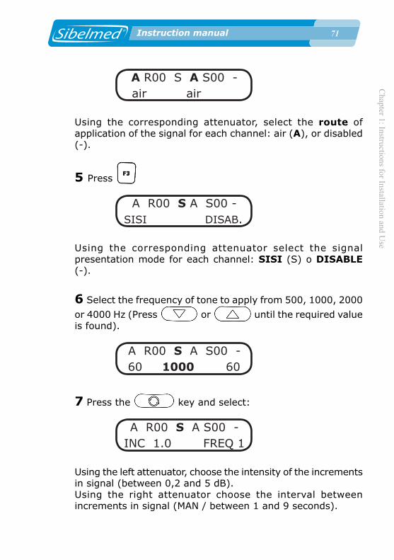
A R00 S A S00 - air air
Using the corresponding attenuator, select the route of application of the signal for each channel: air (A), or disabled (-).
5 Press
A R00 S A S00 - SISI DISAB.
Using the corresponding attenuator select the signal presentation mode for each channel: SISI (S) o DISABLE (-).
6 Select the frequency of tone to apply from 500, 1000, 2000
or 4000 Hz (Press or until the required value is found).
A R00 S A S00 - 60 1000 60
7 Press the key and select:
A R00 S A S00 - INC 1.0 FREQ 1
Using the left attenuator, choose the intensity of the increments in signal (between 0,2 and 5 dB).Using the right attenuator choose the interval between increments in signal (MAN / between 1 and 9 seconds).
�2 Instruction manual
Cha
pter
1: I
nstru
ctio
ns fo
r Ins
talla
tion
and
Use
�2 Instruction manual
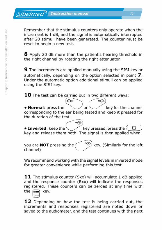
Remember that the stimulus counters only operate when the increment is 1 dB, and the signal is automatically interrupted after 20 stimuli have been generated. The counter must be reset to begin a new test.
8 Apply 20 dB more than the patient's hearing threshold in the right channel by rotating the right attenuator.
9 The increments are applied manually using the SISI key or automatically, depending on the option selected in point 7. Under the automatic option additional stimuli can be applied using the SISI key.
10 The test can be carried out in two different ways:
• Normal: press the or key for the channel corresponding to the ear being tested and keep it pressed for the duration of the test.
• Inverted: keep the key pressed, press the key and release them both. The signal is then applied when
you are NOT pressing the key. (Similarly for the left channel)
We recommend working with the signal levels in inverted mode for greater convenience while performing this test.
11 The stimulus counter (Sxx) will accumulate 1 dB applied and the response counter (Rxx) will indicate the responses registered. These counters can be zeroed at any time with the key.
12 Depending on how the test is being carried out, the increments and responses registered are noted down or saved to the audiometer, and the test continues with the next

Chapter 1: Instructions for Installation and U
se
�� Instruction manual
frequency.
The results recorded are usually expressed as a percentage representing % = No. of responses x 100 / No. of increments
13 Once all frequencies have been tested for the right ear, the test proceeds with the left ear.An audiometric file output via a printer is shown at the end of this chapter.
1.11. PROCEDURE FOR SPEECH AUDIOMETRY TEST
The general aspects and the preparation for and instructions to the patient are as described at the beginning of section 1.9. PROCEDURE FOR TONE AUDIOMETRY.
Before explaining the procedure for performing the test, it is convenient to present the characters which may appear on the screen. These show the operational status of the device at all times.As mentioned previously, the screen consists of two lines of 16 alphanumeric characters each. On the first line, the characters located in positions 0 to 7 refer to the right channel and those located at positions 8 to 15 to the left channel.
The characters which can appear in each of the positions on the screen when a test is being carried out are described below.
ABCDEFGHIJKLMNOPABCDEFGHIJKLMNOP
On the first line:
A and J Route of application (A Air Conduction / C Free (Optional) Field / - Disabled)

�� Instruction manual
Cha
pter
1: I
nstru
ctio
ns fo
r Ins
talla
tion
and
Use
�� Instruction manual
Select with + left or right attenuator, depending on the channel.
CDE and LMN Signal source (SP: Speech audiometry / SPN: Masking with Speech Noise)
Select with + left or right attenuator, depending on the channel.
G and P Mode o f presentat ion o f the s igna l (C Continuous / “P“Pulsating).
Select with + left or right attenuator, depending on the channel.
On pressing the key, for 1 second:
NQ F1: AUX / MIC DV10 03
The input device (MICROPHONE (microphone for the technician) / AUXILIARY) appears in positions 4 to 13. The selected device starts blinking.
Select with .
On the second line:
ABC and NOP Signal level applied to the patient in "dB" ABC right channel. Select with right attenuator.NOP left channel. Select with left attenuator. FGHIJ Number of correct responses/Number of words
Increment the number of correct responses with the key In positions 4 to 13, on pressing the signal keys
or a vumeter appears indicating the

Chapter 1: Instructions for Installation and U
se
�� Instruction manual
intensity of the signal the patient hears.
This disappears on pressing to save the threshold or when the signal is stopped.
On pressing the key, for 1 second
AB Number of words Select with right attenuator, (NUMBER OF QUESTIONS NQ) to ask the patient during the test.
OP Device Volumen (DV) applied to the patient Using the left attenuator, select the level of signal to be applied to the patient.
Speech audiometry essentially consists of determining the threshold of intelligibility (the patient hears and understands words pronounced) using a list of words spoken live or via recorded material.
There is little standardisation of this test either in terms of the procedure to be followed or the material to use, so these are left to the discretion of the specialist.
In this section we only provide a basic description of how to use the equipment in this mode.
The requirements in terms of general aspects, preparation and patient instructions are similar to those described in the section DETERMINATION OF THE HEARING THRESHOLD VIA AIR CONDUCTION WITHOUT MASKING . It is important to explain the test method to the patient and that they will hear a series of words which they are required to repeat.With the audiometer set up as indicated in section 1.5 INSTALLATION AND START-UP, the test proceeds as follows:
1 Press the key. Using the and keys

�� Instruction manual
Cha
pter
1: I
nstru
ctio
ns fo
r Ins
talla
tion
and
Use
�� Instruction manual
select the option:
MENU1. TEST
TEST3.SPEECH
and access the test pressing the key.
2 A screen appears showing the configured options. By default these are the following:
A SP C A SPA C 60 00/10 60
3 Press the key
NEW PATIENT Ref:
Enter the reference and press .
If the thresholds of the previous patient have not been saved to the database, the unit displays a screen for saving them:
SAVE PREVIOUSF1:YES F3:NO
Likewise, a test being performed can be restarted by entering the same reference again:

Chapter 1: Instructions for Installation and U
se
�� Instruction manual
SAVE PREVIOUSF1:YES F3:NO
Select F1 to delete all the thresholds saved for the current test and start the test again.
NOTE: When ELI diagnosis is selected, after the previous
screen the following appear:
NEW PATIENT Age:
NEW PATIENT Sex: Man
4 Press
A SP C A SP CAIR AIR
Using the corresponding attenuator, select the route of application of the signal for each channel: air (A), free field (F).
5 Press Using the corresponding attenuator, select the signal source: speech audiometry (SP), or masking with speech noise (SPN).
A SP C A SP CSPEECH SPEECH
6 Press Using the corresponding attenuator, select the mode of

�� Instruction manual
Cha
pter
1: I
nstru
ctio
ns fo
r Ins
talla
tion
and
Use
�� Instruction manual
presentation of the signal: continuous (C), pulsating (P).
A SP C A SP CCONTIN. CONTIN.
7 Choose the intensity of the signal applied to the patient in dB by rotating the attenuators until the required value is found.
A SP C A SP C 60 00/10 60
8 Press , for 1 second:
NQ F1: AUX / MIC DV 10 03
Using select the input device: MICROPHONE (microphone for the technician) or AUXILIARY.
Using the right attenuator, select the number of words.Using the left attenuator, select the level of signal to be applied to the patient.
9 Connect the microphone for the technician carrying out the test if it is a live voice test or the tape recorder if recorded material is being used.
10 If the audiometer is installed in a sound-proof booth, connect the patient's microphone and the headset for the technician carrying out the test to the corresponding connection points.
11 For this test, it is most convenient to work with signal

Chapter 1: Instructions for Installation and U
se
�� Instruction manual
levels in "inverted" mode (a signal is applied without the signal key being pushed) in the relevant channel.
To activate the inverted mode, keep the key pressed, press the key and release them both. Accordingly, there will be a signal when NOT pressing the
.
Do the same for the left channel.
12 Carry out a training test adjusting the level of input signal
applied to the microphone. To do this, push the key,
for 1 second, and apply a pulsating signal or so that the vumeter indication is displayed. Adjust the volume using the right attenuator, so that only the first seven positions of the vumeter are illuminated when talking normally. In this situation, the signal level applied to the patient is as indicated by the position of the attenuator.
The vumeter range is between -20 dB (first position) and 3 dB. (last 3 positions).This comprises the 10 central characters of the LCD. When the first seven characters are activated there is neither increment nor loss in the level of signal applied to the patient (0 dB). Bear in mind that the level of signal applied to the patient depends on the dB level selected for each channel. If the indicator for the level of signal in speech audiometry is fully lit up, this represents an increase in the applied signal of 3 dB. On the other hand, if only the first character is illuminated, this represents a 20 dB reduction in the signal applied.
13 If the device has an intercom, the volume control can be used to adjust the level of the patient's voice in the technician's headset. The intercom can be activated at any time during the SPEECH function.
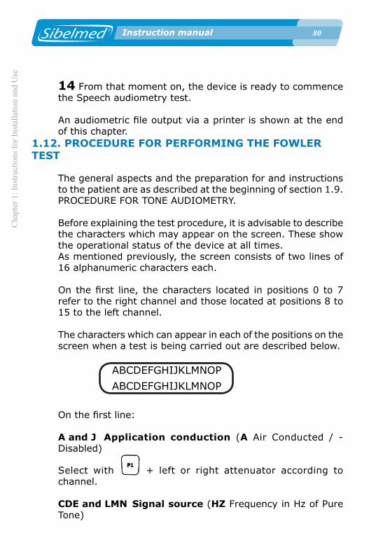
�0 Instruction manual
Cha
pter
1: I
nstru
ctio
ns fo
r Ins
talla
tion
and
Use
�0 Instruction manual
14 From that moment on, the device is ready to commence the Speech audiometry test.
An audiometric file output via a printer is shown at the end of this chapter.
1.12. PROCEDURE FOR PERFORMING THE FOWLER TEST
The general aspects and the preparation for and instructions to the patient are as described at the beginning of section 1.9. PROCEDURE FOR TONE AUDIOMETRY.
Before explaining the test procedure, it is advisable to describe the characters which may appear on the screen. These show the operational status of the device at all times.As mentioned previously, the screen consists of two lines of 16 alphanumeric characters each.
On the first line, the characters located in positions 0 to 7 refer to the right channel and those located at positions 8 to 15 to the left channel.
The characters which can appear in each of the positions on the screen when a test is being carried out are described below.
ABCDEFGHIJKLMNOP
ABCDEFGHIJKLMNOP
On the first line:
A and J Application conduction (A Air Conducted / - Disabled)
Select with + left or right attenuator according to channel.
CDE and LMN Signal source (HZ Frequency in Hz of Pure Tone)

Chapter 1: Instructions for Installation and U
se
�1 Instruction manual
Select with + left or right attenuator according to channel.
G and P Presentation mode of the signal (C Continuous / P Alternated pulse).
Select with + left or right attenuator according to channel.
On the second line:
ABC and NOP Signal level applied to the patient in «dB» ABC right channel. Select with right attenuator.NOP left channel. Select with left attenuator.
DE and LM Two cursors that indicate that the signal is being applied to the patient.
DE right channel. Apply signal with .
LM left channel. Apply signal with .
FGHIJ Frequency in Hz of the applied tone
Select with and .
The Fowler test is also referred to as the Alternate Binaural Loudness Balance test or ABLB. This test is performed to ascertain whether there is recruitment when the hearing threshold is normal or less than 30 dB and the other ear shows a hearing loss of between 25 and 60 dB.
This test procedure consists in sending a tone with the same frequency to both ears, alternating it in both of them once a second. The intensity level for the best ear is progressively increased from the threshold in 10 to 30 dB steps, while the subjective sound levels are equalled in the worst ear, and its relationship with the best ear is plotted on a graph.
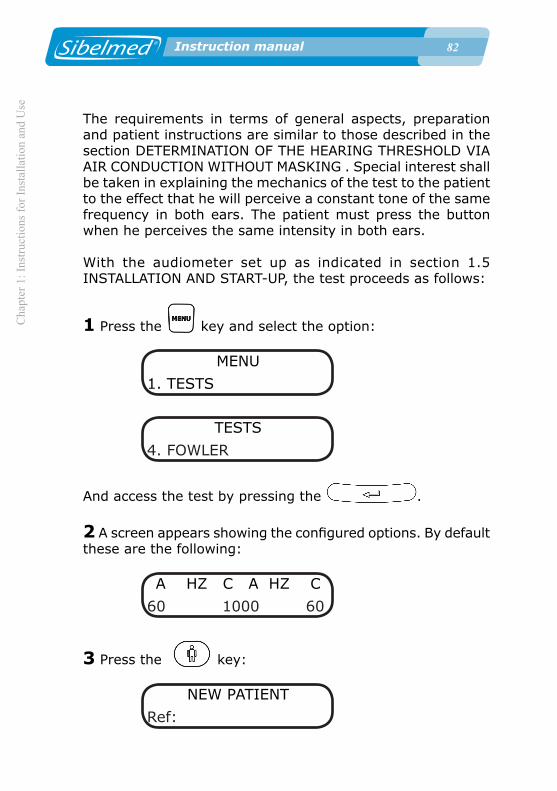
�2 Instruction manual
Cha
pter
1: I
nstru
ctio
ns fo
r Ins
talla
tion
and
Use
�2 Instruction manual
The requirements in terms of general aspects, preparation and patient instructions are similar to those described in the section DETERMINATION OF THE HEARING THRESHOLD VIA AIR CONDUCTION WITHOUT MASKING . Special interest shall be taken in explaining the mechanics of the test to the patient to the effect that he will perceive a constant tone of the same frequency in both ears. The patient must press the button when he perceives the same intensity in both ears.
With the audiometer set up as indicated in section 1.5 INSTALLATION AND START-UP, the test proceeds as follows:
1 Press the key and select the option:
MENU
1. TESTS
TESTS
4. FOWLER
And access the test by pressing the .
2 A screen appears showing the configured options. By default these are the following:
A HZ C A HZ C
60 1000 60
3 Press the key:
NEW PATIENT
Ref:

Chapter 1: Instructions for Installation and U
se
�� Instruction manual
Enter the reference and press .
If there are thresholds that have not been saved (recorded) in the database from the previous patient, the equipment will display the following screen which allows them to be saved:
SAVE PREVIOUS
F1: YES F3: NO
Similarly, the current test can be cancelled by entering the same reference again:
NEW TEST
F1: YES F3: NO
Select to delete all the thresholds of the current test that have been saved and start it again.
NOTE: When ELI diagnosis is selected, the following screen appears afterwards:
NEW PATIENT
Age:
NEW PATIENT
Sex: Male
4 Press the key

�� Instruction manual
Cha
pter
1: I
nstru
ctio
ns fo
r Ins
talla
tion
and
Use
�� Instruction manual
A HZ C A HZ
AIR AIR
Use the corresponding attenuator to select the application conduction of the signal for each channel: aerial (A), or disabled (-).
5 Press
A HZ C A HZ
TONE TONE
Use the corresponding attenuator to select the source of the signal for each channel: in this case only the frequency in Hz of the pure tone (HZ).
6 Press the
A HZ C A HZ
CONTIN. CONTIN.
Use the corresponding attenuator to select the signal presentation mode for each channel: continuous signal (C) or alternated pulse signal (P).
7 Choose the intensity of the signal by rotating the attenuators until the required value is found.
A HZ C A HZ
60 1000 60
8 Select the frequency of the tone between 125 and 8000
Hz by using the and .

Chapter 1: Instructions for Installation and U
se
�� Instruction manual
A HZ C A HZ
60 1000 60
9 The test can be carried out in two different ways:
• Normal: by pressing the or of the corresponding channel.
• Inverted: by keeping the or key pressed, pressing the INVER key and releasing both of them. This way, the signal appears when the silencers are NOT pressed.
In this test, the frequency and intensity levels (for both channels) that the patient states he has heard at the same level
in both ears are saved. To save this threshold the must be pressed. The following screen will appear:
FOWLER TEST
THRESHOLD SAVED
10 If we want to modify the frequency for exploration while the test is being performed, the previous threshold values can be deleted or retained on the audiometer. To do so, simply select the desired option on the following screen:
DEL. THRESHOLDS
F1:YES F3: NO
1.13. TONE DECAY TEST PROCECURE
The general aspects and the preparation for and instructions to the patient are as described at the beginning of section 1.9.
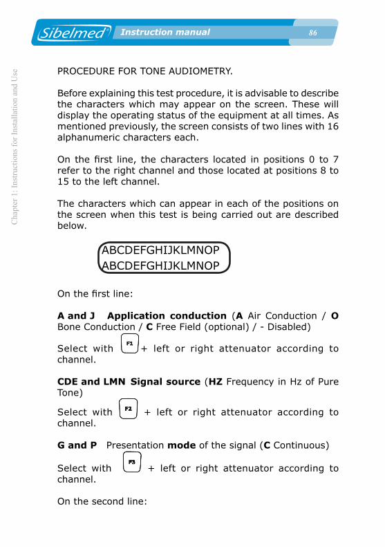
�� Instruction manual
Cha
pter
1: I
nstru
ctio
ns fo
r Ins
talla
tion
and
Use
�� Instruction manual
PROCEDURE FOR TONE AUDIOMETRY.
Before explaining this test procedure, it is advisable to describe the characters which may appear on the screen. These will display the operating status of the equipment at all times. As mentioned previously, the screen consists of two lines with 16 alphanumeric characters each.
On the first line, the characters located in positions 0 to 7 refer to the right channel and those located at positions 8 to 15 to the left channel.
The characters which can appear in each of the positions on the screen when this test is being carried out are described below.
ABCDEFGHIJKLMNOPABCDEFGHIJKLMNOP
On the first line:
A and J Application conduction (A Air Conduction / O Bone Conduction / C Free Field (optional) / - Disabled)
Select with + left or right attenuator according to channel.
CDE and LMN Signal source (HZ Frequency in Hz of Pure Tone)
Select with + left or right attenuator according to channel.
G and P Presentation mode of the signal (C Continuous)
Select with + left or right attenuator according to channel.
On the second line:

Chapter 1: Instructions for Installation and U
se
�� Instruction manual
ABC and NOP Signal level applied to the patient in «dB» ABC right channel. Select with right attenuator.NOP left channel. Select with left attenuator.
DE and LM Two cursors that indicate that the signal is being applied to the patient.
DE right channel. Apply signal with .
LM left channel. Apply signal with .
FGHIJ Frequency in Hz of the applied tone
Select with and .
HI Duration in seconds of the applied signal (displayed when a signal is applied to one of the two channels and hidden when the threshold is saved).
The Carhart Tone Decay test consists in applying a tone that is 5 dB above the threshold to the patient and observing whether he perceives it clearly for 60 seconds.
In normal circumstances, it is perceived during this time. If not, the level is increased in 5 dB steps until it can again be heard and again successively until the patient confirms he can hear the sound for the entire minute.
As mentioned previously, the two central characters on the lower line on the screen become seconds counters, and can count up to 90 seconds. These are activated once the signal is applied.
This test procedure consists in applying a signal level 5 dB above the hearing threshold and a frequency of 250, 500, 1000, 2000 or 4000 Hz.
The test starts by applying the tone using the SIGNAL key in "direct" or "inverted" mode for 60 seconds if the response persists. Otherwise, the tone level is increased.

�� Instruction manual
Cha
pter
1: I
nstru
ctio
ns fo
r Ins
talla
tion
and
Use
�� Instruction manual
The patient responds through the warning connection while he hears the signal. When he ceases to hear it, he releases the button and at that moment the technician presses the
and the time elapsed during hearing is saved
The requirements in terms of general aspects, preparation and patient instructions are similar to those described in the section DETERMINATION OF THE HEARING THRESHOLD VIA AIR CONDUCTION WITHOUT MASKING. Special interest shall be taken in explaining the mechanics of the test to the patient to the effect that he will perceive a constant tone of the same frequency in the ear being studied. He must keep the warning connection pressed while he perceives a signal.
With the audiometer set up as indicated in section 1.5 INSTALLATION AND START-UP, the test proceeds as follows:
1 Press the key and select the option:
MENU
1. TESTS
TESTS
5. TONE DECAY
And access the test by pressing the .
2 A screen appears showing the configured options. By default these are the following:
A HZ C A HZ C
60 1000 60
3 Press the :
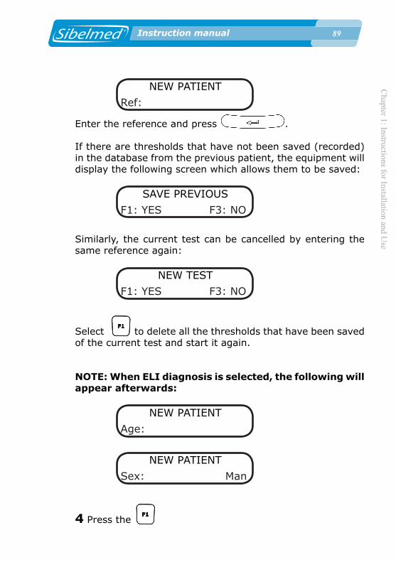
Chapter 1: Instructions for Installation and U
se
�� Instruction manual
NEW PATIENT
Ref:
Enter the reference and press .
If there are thresholds that have not been saved (recorded) in the database from the previous patient, the equipment will display the following screen which allows them to be saved:
SAVE PREVIOUS
F1: YES F3: NO
Similarly, the current test can be cancelled by entering the same reference again:
NEW TEST
F1: YES F3: NO
Select to delete all the thresholds that have been saved of the current test and start it again.
NOTE: When ELI diagnosis is selected, the following will appear afterwards:
NEW PATIENT
Age:
NEW PATIENT
Sex: Man
4 Press the
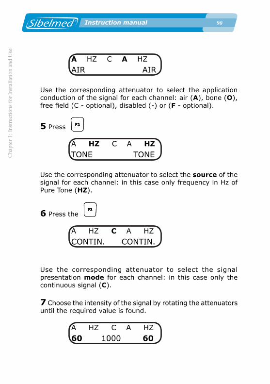
�0 Instruction manual
Cha
pter
1: I
nstru
ctio
ns fo
r Ins
talla
tion
and
Use
�0 Instruction manual
A HZ C A HZ
AIR AIR
Use the corresponding attenuator to select the application conduction of the signal for each channel: air (A), bone (O), free field (C - optional), disabled (-) or (F - optional).
5 Press
A HZ C A HZ
TONE TONE
Use the corresponding attenuator to select the source of the signal for each channel: in this case only frequency in Hz of Pure Tone (HZ).
6 Press the
A HZ C A HZ
CONTIN. CONTIN.
Use the corresponding attenuator to select the signal presentation mode for each channel: in this case only the continuous signal (C).
7 Choose the intensity of the signal by rotating the attenuators until the required value is found.
A HZ C A HZ
60 1000 60

Chapter 1: Instructions for Installation and U
se
�1 Instruction manual
8 Select the frequency of the applied tone between 250, 500
1000, 2000 and 4000 Hz using the and .
A HZ C A HZ
60 1000 60
9 The test can be carried out in two different ways:
• Normal: by pressing the or of the corresponding channel.
• Inverted: by keeping the or pressed, pressing the INVER key and releasing both of them. This way the signal appears when the silencers are NOT pressed.
In this test the intensity level and its duration are recorded.
To save the threshold the must be pressed. The following screen will appear:
TONE DECAY TEST
THRESHOLD SAVED
1.14. LUSCHER TEST PROCEDURE
The general aspects and the preparation for and instructions to the patient are as described at the beginning of section 1.9. PROCEDURE FOR TONE AUDIOMETRY.
Before explaining this test procedure, it is advisable to describe the characters which may appear on the screen. These show the operational status of the device at all times. As mentioned previously, the screen consists of two lines of 16 alphanumeric

�2 Instruction manual
Cha
pter
1: I
nstru
ctio
ns fo
r Ins
talla
tion
and
Use
�2 Instruction manual
characters each.
On the first line, the characters located in positions 0 to 7 refer to the right channel and those located at positions 8 to 15 to the left channel.
The characters which can appear in each of the positions on the screen when this test is being carried out are described below.
ABCDEFGHIJKLMNOPABCDEFGHIJKLMNOP
On the first line:
A and J Application conduction (A Air Conducted / - Disabled)
Select with + left or right attenuator according to channel.
CDE and LMN Signal source (HZ Frequency in Hz of Pure Tone)
Select with + left or right attenuator according to channel.
G and P Presentation mode of the signal (M Modulated)
Select with Y + left or right attenuator according to channel.
On the second line:
ABC and NOP Signal level applied to the patient in «dB» ABC right channel. Select with right attenuator.NOP left channel. Select with left attenuator.
DE and LM Two cursors that indicate that the signal is being applied to the patient.

Chapter 1: Instructions for Installation and U
se
�� Instruction manual
DE right channel. Apply signal with .
LM left channel. Apply signal with .
FGHIJ Frequency in Hz of the applied tone
Select with and .
On pressing the for 1 second:
ABC and NOP Modulation bandwidth: 0.2, 0.3, 0.4, 0.5, 0.6, 0.8, 1, 2, 3, 4 or 5 dB
The Luscher test consists in applying a tone level of 40 dB above the hearing threshold and determining the modulation threshold. This will be at the threshold where the subject ceases to hear or starts to hear the "ripple" of the tone, depending on whether the level rises or falls.
The advantage of this test is that it is carried out on one ear only, so recruitment can be ascertained when the Fowler test is not of any use, due to the symmetry in the hearing loss.
In this test only the modulated mode is activated, as well as the pure tone source and the aerial conduction. The active frequencies are 500, 1000, 2000, 4000 and 8000 Hz. The modulation bandwidth level can be selected at 0.2, 0.3, 0.4, 0.5, 0.6, 0.8, 1, 2, 3, 4 or 5 dB and the frequency setting of the modulation signal is fixedat 2.5 Hz.
The requirements in terms of general aspects, preparation and patient instructions are similar to those described in the section DETERMINATION OF THE HEARING THRESHOLD VIA AIR CONDUCTION WITHOUT MASKING. Special interest shall be taken in explaining the mechanics of the test to the patient to the effect that he will perceive a constant tone of the same frequency with bandwidth modulation in the ear being studied.

�� Instruction manual
Cha
pter
1: I
nstru
ctio
ns fo
r Ins
talla
tion
and
Use
�� Instruction manual
He must press the warning connection when he ceases to hear or starts to hear the ripple in the tone, depending on whether its level is being turned up or down.
With the audiometer set up as indicated in section 1.5 INSTALLATION AND START-UP, the test proceeds as follows:
1 Press the and select the option:
MENU
1. TESTS
TESTS
6. LUSCHER
And access the test by pressing the .
2 A screen appears showing the configured options. By default these are the following:
A HZ M A HZ M
60 1000 60
3 Press the :
NEW PATIENT
Ref:
Enter the reference and press .
If there are thresholds that have not been saved in the database from the previous patient, the equipment will display the following screen which allows them to be saved:
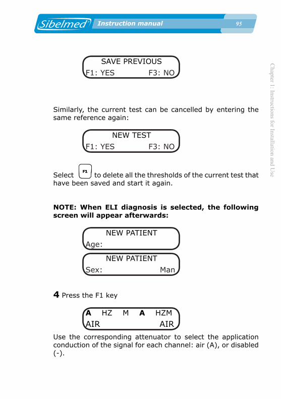
Chapter 1: Instructions for Installation and U
se
�� Instruction manual
SAVE PREVIOUS
F1: YES F3: NO
Similarly, the current test can be cancelled by entering the same reference again:
NEW TEST
F1: YES F3: NO
Select to delete all the thresholds of the current test that have been saved and start it again.
NOTE: When ELI diagnosis is selected, the following screen will appear afterwards:
NEW PATIENT
Age:
NEW PATIENT
Sex: Man
4 Press the F1 key
A HZ M A HZM
AIR AIR
Use the corresponding attenuator to select the application conduction of the signal for each channel: air (A), or disabled (-).

�� Instruction manual
Cha
pter
1: I
nstru
ctio
ns fo
r Ins
talla
tion
and
Use
�� Instruction manual
5 Press
A HZ M A HZ M
TONE TONE
Use the corresponding attenuator to select the source of the signal for each channel: in this case only the frequency in Hz of the pure tone (HZ).
6 Press the
A HZ M A HZ M
MODULA. MODULA.
Use the corresponding attenuator to select the signal presentation mode for each channel: in this case only a modulated (M) signal.
7 Choose the intensity of the signal by rotating the attenuators until the required value is found.
A HZ M A HZ M
60 1000 60
8 Select the frequency of the applied tone between 500, 1000,
2000, 4000 and 8000 Hz using the and .
A HZ M A HZ M
60 1000 60
9 Press the for 1 second: The following screen will appear:

Chapter 1: Instructions for Installation and U
se
�� Instruction manual
A HZ M A HZ M
0.2 2.5 0.2
Select the modulation bandwidth level from 0.2, 0.3, 0.4, 0.5, 0.6, 0.8, 1, 2, 3, 4 or 5 dB by rotating the attenuator of the corresponding channel. The frequency setting of the modulation signal is fixed at 2.5 Hz. Press ENTER to accept the changes and return to the test screen.
10 The test can be carried out in two different ways:
• Normal: by pressing the or of the corresponding channel.
• Inverted: by keeping the or pressed, pressing the INVER key and releasing both of them. This way the signal appears when the silencers are NOT pressed.
In this test the modulation bandwidth level and the frequency
are recorded. To save the threshold the must be pressed. The following screen will appear:
LUSCHER TEST
THRESHOLD SAVED
1.15. WEBER TEST PROCEDURE
The general aspects and the preparation for and instructions to the patient are as described at the beginning of section 1.9. PROCEDURE FOR TONE AUDIOMETRY.
Before explaining this test procedure, it is advisable to describe the characters which may appear on the screen. These show the operational status of the device at all times. As mentioned

�� Instruction manual
Cha
pter
1: I
nstru
ctio
ns fo
r Ins
talla
tion
and
Use
�� Instruction manual
previously, the screen consists of two lines of 16 alphanumeric characters each.
On the first line, the characters located in positions 0 to 7 refer to the right channel and those located at positions 8 to 15 to the left channel.
The characters which can appear in each of the positions on the screen when this test is being carried out are described below.
ABCDEFGHIJKLMNOPABCDEFGHIJKLMNOP
On the first line:
A and J Application conduction (O Bone Conducted / - Disabled)
Select with + left or right attenuator according to channel.
CDE and LMN Signal source (HZ Frequency in Hz of Pure Tone)
Select with + left or right attenuator according to channel.
G and P Presentation mode of the signal (C Continuous)
Select with + left or right attenuator according to channel.
On the second line:
ABC and NOP Signal level applied to the patient in «dB» ABC right channel. Select with right attenuator.NOP left channel. Select with left attenuator.
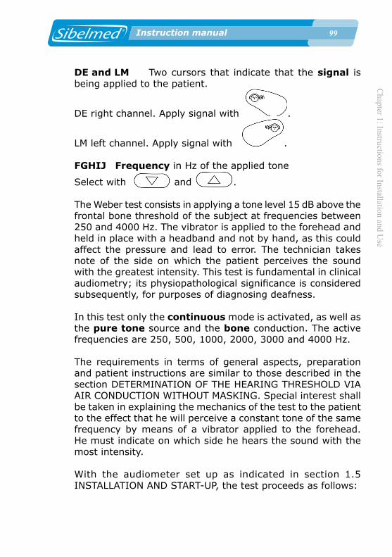
Chapter 1: Instructions for Installation and U
se
�� Instruction manual
DE and LM Two cursors that indicate that the signal is being applied to the patient.
DE right channel. Apply signal with .
LM left channel. Apply signal with .
FGHIJ Frequency in Hz of the applied tone
Select with and .
The Weber test consists in applying a tone level 15 dB above the frontal bone threshold of the subject at frequencies between 250 and 4000 Hz. The vibrator is applied to the forehead and held in place with a headband and not by hand, as this could affect the pressure and lead to error. The technician takes note of the side on which the patient perceives the sound with the greatest intensity. This test is fundamental in clinical audiometry; its physiopathological significance is considered subsequently, for purposes of diagnosing deafness.
In this test only the continuous mode is activated, as well as the pure tone source and the bone conduction. The active frequencies are 250, 500, 1000, 2000, 3000 and 4000 Hz.
The requirements in terms of general aspects, preparation and patient instructions are similar to those described in the section DETERMINATION OF THE HEARING THRESHOLD VIA AIR CONDUCTION WITHOUT MASKING. Special interest shall be taken in explaining the mechanics of the test to the patient to the effect that he will perceive a constant tone of the same frequency by means of a vibrator applied to the forehead. He must indicate on which side he hears the sound with the most intensity.
With the audiometer set up as indicated in section 1.5 INSTALLATION AND START-UP, the test proceeds as follows:

100 Instruction manual
Cha
pter
1: I
nstru
ctio
ns fo
r Ins
talla
tion
and
Use
100 Instruction manual
1 Press the and select the option:
MENU
1. TESTS
TESTS
7. WEBER
And access the test by pressing the .
2 A screen appears showing the configured options. By default these are the following:
B HZ C - HZ C60 1000 60
3 Press the :
NEW PATIENT
Ref:
Enter the reference and press .
If there are thresholds that have not been saved in the database from the previous patient, the equipment will display the following screen, which allows them to be saved:

Chapter 1: Instructions for Installation and U
se
101 Instruction manual
SAVE PREVIOUS
F1: YES F3: NO
Similarly, the current test can be cancelled by entering the same reference again:
NEW TEST
F1: YES F3: NO
Select to delete all the thresholds of the current test that have been saved and start it again.
NOTE: When ELI diagnosis is selected, the following screen will appear afterwards:
NEW PATIENT
Age:
NEW PATIENT
Sex: Man
4 Press the
B HZ C - HZ CBONE DISABLED.
Use the corresponding attenuator to select the application conduction of the signal for each channel: bone (O) or disabled (-).
5 Press

102 Instruction manual
Cha
pter
1: I
nstru
ctio
ns fo
r Ins
talla
tion
and
Use
102 Instruction manual
B HZ C - HZ CTONE TONE
Use the corresponding attenuator to select the source of the signal for each channel: in this case only the frequency in Hz of the pure tone (HZ).
6 Press the
B HZ C - HZ CCONTEN. CONTEN.
Use the corresponding attenuator to select the signal presentation mode for each channel: in this case only the continuous signal (C).
7 Choose the intensity of the signal by rotating the attenuators until the required value is found.
B HZ C - HZ C60 1000 60
8 Select the frequency of the applied tone between 250,
500, 1000, 2000, 3000 and 4000 Hz by using of the
and .
B HZ C - HZ C60 1000 60
9 The test can be carried out in two different ways:

Chapter 1: Instructions for Installation and U
se
10� Instruction manual
• Normal: by pressing the or of the corresponding channel.
• Inverted: by keeping the or pressed, pressing the INVER key and releasing both of them. This way the signal will appear when the silencers are NOT pressed.
In this test, the side and the frequency at which the patient states hearing with the greatest intensity are recorded. To
save the threshold the key must be pressed. The following screen will appear:
R.E. LEVEL L.E.
F1:> F2:= F3:<
Press the if the patient perceived the tone with more
intensity with the right ear, if he perceived it with the
greatest intensity with the left ear and if no difference was noticed between both ears. Then save the threshold:
WEBER TESTTHRESHOLD SAVED
1.16 PURE TONE HF TEST PROCEDURE
The general aspects and the preparation and instructions to the patient are described at the beginning of section 1.9. PROCEDURE FOR TONE AUDIOMETRY
Before explaining this test procedure, it is advisable to describe the characters which may appear on the screen.

10� Instruction manual
Cha
pter
1: I
nstru
ctio
ns fo
r Ins
talla
tion
and
Use
10� Instruction manual
These show the operational status of the device at all times. As mentioned previously, the screen consists of two lines of 16 alphanumeric characters each.
On the first line, the characters located in positions 0 to 7 refer to the right channel and those located at positions 8 to 15 to the left channel.
The characters which can appear in each of the positions on the screen when this test is being carried out are described below.
ABCDEFGHIJKLMNOPABCDEFGHIJKLMNOP
On the first line:
A and J Application conduction (A Air Conducted / - Disabled)
Select with + left or right attenuator according to channel.
CDE and LMN Signal Source (HZ Frequency in Hz of Pure Tone / NBN Narrow Band Noise / WN White Noise)
Select with + left or right attenuator according to channel.
G and P Presentation Mode of the signal (C Continuous / P Pulsating)
Select with + left or right attenuator according to channel.
On the second line:
ABC and NOP Signal level applied to the patient in «dB»

Chapter 1: Instructions for Installation and U
se
10� Instruction manual
ABC right channel. Select with right attenuator.NOP left channel. Select with left attenuator.
DE and LM Two cursors that indicate that the signal is being applied to the patient.
DE right channel. Apply signal with .
LM left channel. Apply signal with .
FGHIJ Frequency in Hz of the applied tone
Select with or .
The Pure Tone HF test consists of a pure tone test, in which the hearing thresholds can be determined for frequencies higher than 8.000 Hz. The SIBELSOUND 400 audiometer allows the 9.000, 10.000, 11.200, 12.500, 14.000, 16.000, 18.000 y 20.000 Hz frequencies, besides the frequencies of 125 to 8.000 Hz. In this test, only the air conduction is active, the pure tone, narrow band noise and white noise as sources and continuous and pulsating modes. The requirements in terms of general aspects, preparation and patient instructions are similar to those described in the section DETERMINATION OF THE HEARING THRESHOLD VIA AIR CONDUCTION WITHOUT MASKING. Special interest shall be taken in explaining the mechanics of the test to the patient. He will perceive tones of several frequencies to different intensities. Pressing the response button, the patient must indicate the level he starts perceiving the tone that will determine the hearing threshold.
To realize pure tone high frequency audiometries with masking, general aspects, preparation and patient instructions are similar to those described in the section DETERMINATION OF THE HEARING THRESHOLD VIA AIR CONDUCTION WITH MASKING.

10� Instruction manual
Cha
pter
1: I
nstru
ctio
ns fo
r Ins
talla
tion
and
Use
10� Instruction manual
With the audiometer set up as indicated in section 1.5 INSTALLATION AND START-UP, the test proceeds as follows:
1 Press the key and select the option:
MENU1. TESTS
TESTS8. PURE TONE HF
And access the test by pressing the key.
2 A screen appears showing the configured options. By default these are the following:
A HZ C A HZ C60 8000 60
3 Press the key:
NEW PATIENTRef:
Enter the reference and press . If there are thresholds that have not been saved in the database from the previous patient, the equipment will display the following screen, which allows them to be saved:

Chapter 1: Instructions for Installation and U
se
10� Instruction manual
SAVE PREVIOUSF1: YES F3:NO
Similarly, the current test can be cancelled by entering the same reference again:
NEW TESTSF1: YES F3:NO
Select to delete all the thresholds of the current test that have been saved and start it again.
NOTE: When ELI diagnosis is selected, the following screen will appear afterwards:
NEW PATIENTAge (y):
NEW PATIENTSex: Man
4 Press the key
A HZ C A HZ CAIR AIR
Use the corresponding attenuator to select the application conduction of the signal for each channel: air (A) or disabled (-).
5 Press the key

10� Instruction manual
Cha
pter
1: I
nstru
ctio
ns fo
r Ins
talla
tion
and
Use
10� Instruction manual
A HZ C A HZ CTONE TONE
Use the corresponding attenuator to select the source of the signal for each channel: Hz of pure tone (HZ), narrow band noise (NBN) or white noise (WN)
6 Press the key
A HZ C A HZ CCONTIN. CONTIN.
Use the corresponding attenuator to select the signal presentation mode for each channel: continuous (C) or pulsating (P).
7 Choose the intensity of the signal by rotating the attenuators until the desired value is found.
A HZ C A HZ C60 8000 60
8 Select the frequency of the applied tone in the range of
125 to 20.000 Hz by using the or keys.
A HZ C A HZ C60 8000 60
9 The test can be carried out in two different ways:
• Normal: by pressing the or keys of the

Chapter 1: Instructions for Installation and U
se
10� Instruction manual
corresponding channel.
• Inverted: keep the or key pressed, press the key and release both of them. This way the signal will appear when the silencers are NOT pressed.
Like in the pure tone test, frequency and threshold level of intensity for every channel are saved, in which the patient had pressed the response button. If the test has been realized with masking, the level of applied noise is also stored. To save the
threshold, key must be pressed. The following screen will appear:
TONE HF TESTTHRESHOLD SAVED
1.17. PROCEDURE FOR FREE AUDIOMETRY
As explained above, many of the audiometric tests have several variants in terms of the procedure to be followed, so that to describe them all would be very lengthy, and moreover likely to involve omissions or errors. Therefore options have been provided for the SIBELSOUND 400 audiometer to simplify the execution of each kind of test.
However, specialists for whom the options described are too limited can use the free audiometry option to carry out such tests as they wish without being limited by the software, subject only to the capabilities of the audiometer.
This audiometer option MUST NOT BE CONFUSED WITH FREE FIELD. By selecting "Free Audiometry" the user can carry out any other test with the audiometer, including those described above, as the audiometer permits access to and selection of all of its functions, even though some may appear absurd.
With this option it is not possible to produce reports or save

110 Instruction manual
Cha
pter
1: I
nstru
ctio
ns fo
r Ins
talla
tion
and
Use
110 Instruction manual
tests in the database.
REFERENCE TONE (OPTIONAL)
This option allows increase/decrease in the level of signal applied the patient in steps of 1 dB and is only active in Free tests (where this option is selected), so the test cannot be printed or saved in the database. This option is deactivated automatically after 15 minutes during which no key on the device has been pressed.To select the reference tone:
1 From the Main Menu access the option
MENU5. REF. TONE
2 Using the attenuators, select the reference tone (ON-1dB)
and press to accept or to cancel;
REF. TONEON 1dB
1.18. DIAGNOSTIC CALCULATIONS
The SIBELSOUND 400 audiometer can determine the following diagnoses based on their respective parameters:
1 “MINISTRY” DIAGNOSIS ACCORDING TO THE MINISTRY OF LABOUR AND SOCIAL AFFAIRS OSB No. 22 (January 26, 2000)
2 DIAGNOSIS OF THE COUNCIL OF PHYSICAL THERAPY
3 DIAGNOSIS OF THE MEXICAN INSTITUTE OF SOCIAL

Chapter 1: Instructions for Installation and U
se
111 Instruction manual
SECURITY
4 ELI (Early Loss Index)
5 SAL INDEX (Speech Average Loss)
6 KLOCKHOOF DIAGNOSIS (Modified by the Lavoro Clinic of Milan)The parameters for each diagnosis and the calculation method of each are described in APPENDIX 3 of this manual.
Diagnoses are only calculated for Pure Tone and Pure Tone HF tests. If both tests are realized, only Pure Tone test results are shown.
1.19. PRINTING AND SAVING AUDIOMETRIC TESTS
The SIBELSOUND 400 audiometer can print and/or save certain audiometric tests to the device itself or to an external database.The audiometer can save the hearing thresholds detected to a temporary memory. As mentioned above, this operation can be carried out by pressing after evaluating a threshold.
To review these thresholds press the key. Once in review mode, use the attenuators to select the route and the
/ keys to explore the thresholds saved during the various tests.
Once the thresholds are saved you can do any of the following:• Print the audiometric data using an external printer.• Save the audiometric data to an INTERNAL DATABASE.• Transfer the audiometric data to an EXTERNAL DATABASE
ON A PC.

112 Instruction manual
Cha
pter
1: I
nstru
ctio
ns fo
r Ins
talla
tion
and
Use
112 Instruction manual
PRINTING AUDIOMETRIC DATA
A. Type of printer
The device is capable of controlling any printer that works with IBM GRAPHICS or HP PCL.We recommend using an inkjet printer with a low noise level.
B. Tests which can be printed
The information which can be printed is everything defined in section 1.8. AUDIOMETRIC TESTS, with the exception of the FREE AUDIOMETRY option.
• TONE AUDIOMETRY• SISI TEST• SPEECH AUDIOMETRY• FOWLER• TONE DECAY• LUSCHER• WEBER• PURE TONE HF.
C. Printing the Report
The process to follow when carrying out the tests you wish to print is as follows:
1 Press the key and assign a reference number of up to 10 characters to the patient being tested. This reference is entered with the keys which are associated with the digits from 0 to 9 and confirmed with the key.
2 Carry out the audiometric test on the patient as described in section 1.9 PROCEDURE FOR TONE AUDIOMETRY and subsequent sections.
The following considerations apply depending on the type of test:

Chapter 1: Instructions for Installation and U
se
11� Instruction manual
TONE AUDIOMETRY
The only proviso is that, once each hearing threshold has been determined, along with the level for the channel corresponding
to that threshold, the key must be pressed for a few seconds until the message "THRESHOLD SAVED" appears on the screen. If masking is being applied to the other ear, it
must be at the right level before pressing .
WARNINGSaving of data is carried out independently for each threshold and each level of masking, if applicable. The device only saves the latest threshold detected before pressing the key.
To remind the technician to save the thresholds, the audiometer generates a warning before the next one begins, via the following screen:
SAVE THRESHOLDF1: YES F3:NO
If the audiometry is pure tone, this warning appears when there is a patient registered in the device, the signal has been applied and the user attempts to change the frequency, the path or the source
SISI TEST
In this test, once the twenty 1 dB signal increases have been applied to the patient and the latter has provided the corresponding responses (assuming they were heard) press the key and the device saves the increment and response counters.The save threshold warning appears when there is a patient
11� Instruction manual
Cha
pter
1: I
nstru
ctio
ns fo
r Ins
talla
tion
and
Use
11� Instruction manual
registered in the device, stimuli have been applied and the user attempts to modify the intensity, the pathway or mode of the signal, or there is an attempt to reset the stimuli and responses.
If the frequency is modified when a patient is registered in the device and stimuli have been applied, the threshold is saved automatically.
SPEECH AUDIOMETRY
In speech audiometry, we enter the number of words sent to the patient and received from the latter at a determined level.
With the level selector in the correct position, press and the audiometer saves the number of words
applied and the correct responses received.
The save threshold warning appears when there is a patient registered in the device, the signal has been applied and an attempt is made to modify the intensity, the pathway or the signal source, or if an attempt is made to reset the number of correct responses.
FOWLER
In the Fowler test, once the signal has been applied to the patient in both ears and the patient presses the button to notify equal perception of level in both ears, press the ENTER key to record the frequency and the intensity levels on the machine.
The warning to record the threshold appears when a patient has been registered on the machine, a signal has been applied and someone attempts to change the signal conduction or source. If the frequency is changed and thresholds have been

Chapter 1: Instructions for Installation and U
se
11� Instruction manual
saved, the machine will either allow for these to be deleted or for them to be added to the new frequency.
TONE DECAY
In the Tone Decay test, once the signal is applied to the patient's ear and the patient stops pressing the warning button, press the key to record the time elapsed during the audition on the machine.
The warning to save the threshold appears when a patient has been registered in the machine, a signal has been applied and someone attempts to change the intensity, the conduction, the source or the signal mode, or if someone attempts to reset the seconds counter.
LUSCHER
In the Luscher test, the patient uses the connection to notify when he ceases to hear or begins to hear the ripple of the applied tone, depending on whether its level is rising or falling. At that time, the technician must press the key and the machine will save the modulation level and the frequency.
The save threshold warning appears when a patient has been registered on the machine, a signal has been applied and someone attempts to change the frequency, the signal conduction or the source.
WEBER
In the Weber test, the patient notifies which ear perceives the tone applied by the vibrator with the greatest intensity or if both ears perceive it with equal intensity. At that time, the technician must press the and select the ear indicated by the patient.

11� Instruction manual
Cha
pter
1: I
nstru
ctio
ns fo
r Ins
talla
tion
and
Use
11� Instruction manual
The save threshold warning appears when a patient has been registered on the machine, a signal has been applied and someone attempts to change the frequency, the signal conduction or the source.
PURE TONE HF
Like in the pure tone audiometry, once each hearing threshold has been determined, along with the level for the channel corresponding to that threshold, the key must be pressed and for a few seconds the message “THRESHOLD SAVED” appears on the screen. If masking is being applied to the other ear, it must be at the right level before pressing INTRO.
WARNING
Saving of data is carried out independently for each threshold and each level of masking, if applicable. The device only saves the latest threshold detected before pressing the key.
The warning to record the threshold appears when a patient has been registered on the machine, signal has been applied and someone attempts to change the frequency, signal conduction or source.
FREE AUDIOMETRY
Having performed the tests, if you entered via this option you can neither print nor save the results in the database.
3 With the hearing thresholds in the temporary memory, these
can be reviewed for queries or errors. Pressing the key, each of the hearing thresholds held in the memory is shown. In the central part of Line 1 you can see the type of

Chapter 1: Instructions for Installation and U
se
11� Instruction manual
test (TNL, SSI, SP, FWL, DEC, LCH, WBR, THF). The remainder of the information depends on the type of test selected, corresponding to:
1. Tone Audiometry: Threshold, pathway and mask. If masking has been applied, the level is indicated above the threshold.
A --- TNE A ---60 1000 60
2. Sisi test: Percentage and pathway.
A SSI A75% 1000 100%
3. Speech audiometry: Threshold and percentage of correct answers displayed, pathway and mask. If masking has been applied, the level is indicated above the threshold.
A --- SP A ---60 100% 75% 60
4. Fowler: threshold, frequency and conduction.
A FWL A60 1000 60
5. Tone Decay: seconds (on the first line) and threshold, frequency and conduction (on the second line).
A 15 DEC A60 1000 60
6. Luscher: threshold (modulation level), frequency and

11� Instruction manual
Cha
pter
1: I
nstru
ctio
ns fo
r Ins
talla
tion
and
Use
11� Instruction manual
conduction.
A LCH A0.3 1000 0.2
7. Weber: frequency, side (>, = or <) and conduction:
B WBR BR.E.<L.E 1000
8. Pure Tone HF: Threshold, frequency, conduction and mask. If masking has been applied, the level is indicated above the threshold.
A --- THF A ---60 8000 60
4 If a threshold has been entered incorrectly it is repeated for the corresponding frequency and channel.
5 When carrying out more than one kind of test for the same patient, it is not necessary to print a report after each test separately. All the results can be printed together at the end.
6 On completing the test, press the key and the report will be printed automatically.
Press the key to cancel printing.
The information on the Tone, SISI and Luscher tests is printed on the first page.
The information on the Tone Decay, Fowler, Weber and SPEECH tests is printed on the second page.
Chapter 1: Instructions for Installation and U
se
11� Instruction manual
On the third page Pure Tone HF results are printed.
On the fourth page diagnosis results are printed.
Each of these last three pages are only printed out if a Tone Decay, Fowler, Weber, Speech or Pure Tone HF tests are carried out or if more tan one diagnosis has been selected in the configuration.
An audiometric file output via a printer is shown at the end of this chapter.
SAVING AUDIOMETRIC DATA IN THE INTERNAL DATABASE
The SIBELSOUND 400 audiometer has a FLASH memory with capacity for more than 1000 tone tests via air conduction and bone conduction in both channels at the frequencies 500, 1000, 2000, 3000 and 4000 Hz.
This stored information can be used for:
• Subsequent transfer to a database on a PC (See section 1.15. COMMUNICATIONS SYSTEMS)• Printing using an external printer.
SAVING A TEST
To save a test in the database press the key. The test is saved in its existing state.
A screen then appears similar to the following (the first line depends on the test carried out):
TYPE OF TESTTEST SAVED

120 Instruction manual
Cha
pter
1: I
nstru
ctio
ns fo
r Ins
talla
tion
and
Use
120 Instruction manual
VIEWING, PRINTING AND DELETION OF SAVED TESTS
To view the tests saved in the database proceed as follows:
1 Access the Options Menu by pressing the key or
pressing the from the test screen.
2 Select the option
MENU4. DATABASE
and press .
3 Then select
DATABASE1. VER
and press . The user can also access the previous
screen directly by pressing the key for 1 second from
the test screen. If there are no thresholds to save, the key can be pressed as normal.
The following screen appears:
Rec 1/10 Ref: 12345

Chapter 1: Instructions for Installation and U
se
121 Instruction manual
4 From this screen you can print the patient's tests by
pressing :
Rec 1/10PRINTING
5 From this screen, the patient's tests can be deleted by
pressing + .
DELETE PATIENT F1: YES F3:NO
6 Select the required patient, navigating through the database
using the attenuators and press .
The following screen appears:
12345 TONE21-07-05 11:35
7 At this point you may:
• Print the tests for the selected patient by pressing
12345 TONEPRINTING
• Select other tests for the same patient (if any), using the attenuators.

122 Instruction manual
Cha
pter
1: I
nstru
ctio
ns fo
r Ins
talla
tion
and
Use
122 Instruction manual
• View the test values by pressing In this case a screen similar to the following appears:
A --- TNL A --- 60 1000 ---
CLEARING THE INTERNAL DATABASE
To clear the internal database of data, follow these steps:
1 Access the Options Menu by pressing the key
2 Select the option
MENU4. DATABASE
and press .
The user can also access the previous screen directly by
pressing the key for 1 second from the test screen. If
there are no thresholds to save, the key can be pressed as normal.
3 Then select
DATABASE 2. CLEAR DB
and press . The following screen appears

Chapter 1: Instructions for Installation and U
se
12� Instruction manual
CLEAR DBF1:YES F3:NO
4 Press key to clear the database and the following message appears:
CLEARING DB ıııııııııııııı
Warning:This process destroys all information held in the Internal Database and it can NOT be RECOVERED.
FINDING A PATIENT IN THE INTERNAL DATABASE
To find a patient in the internal database proceed as follows:
1 Access the Options Menu by pressing the key.
2 Select the option
MENU4. DATABASE
and press .
The user can also access the previous screen directly by
pressing the key for 1 second from the test screen. If
there are no thresholds to save, the key can be pressed as normal.
3 Then select

12� Instruction manual
Cha
pter
1: I
nstru
ctio
ns fo
r Ins
talla
tion
and
Use
12� Instruction manual
DATABASE3. PAT. SEARCH
and press , (access is also possible by pressing
the key from within the Database menu). The following screen appears
PATIENT SEARCHRef:
Enter the reference for the patient you wish to find using the numeric keypad. If the patient is stored in the Database, the following screen appears:
Rec 1/10Ref: 12345
DELETE A PATIENT FROM THE DATABASE
To delete a patient from the internal database proceed as follows:
1 Access the Options Menu by pressing the . key.
2 Select the option
MENU4. DATABASE
and press . The user can also access the previous
screen directly by pressing the key for 1 second from

Chapter 1: Instructions for Installation and U
se
12� Instruction manual
the test screen. If there are no thresholds to save, the key can be pressed as normal.
3 Then select
DATABASE 4. CLEAR PATIENT
and press . The following screen appears:
Rec 1/10Ref: 12345
Use the attenuators to select the patient to be deleted and press .
DELETE PATIENTF1:YES F3:NO
Press to confirm and delete the patient or to return to the previous screen.
1.20. COMMUNICATIONS SYSTEMS
One of the features of the SIBELSOUND 400 is the Communications System with other media which allows it to:
• Transfer information from the device's internal database to a PC.
• Communicate in real time with a PC.
• Export patient tests to other Management Systems.

12� Instruction manual
Cha
pter
1: I
nstru
ctio
ns fo
r Ins
talla
tion
and
Use
12� Instruction manual
• Update the device's internal Firmware.
These communications can be carried out, using the relevant software, via two distinct channels:
• Serial RS232C (Optional)
• USB (standard)
To install the USB module referred to the Instructions for Use for the W50 Audiometry Software.
TRANSFER OF TESTS TO THE PC
If you wish to view, print, or manage the tests saved in the internal database of the audiometer and/or store them using a PC, you need to use the W-50 Audiometry Software.
The process to carry out the transfer is as follows:
1 Save the tests you require in the device's Internal Database.
2 Install the W-50 Audiometry Software, as described in the Instructions for Use.
3 From the PC load the data in the database using the option Import tests from the menu Options – Importing tests in the W-50 Software.
4 The screen displays a list of the tests stored in the device. Select the ones you wish to import into the PC Database(the one chosen using the W-50 Software).
5 From this point you can select, view or print any of the tests imported or transferred to the PC.
Chapter 1: Instructions for Installation and U
se
12� Instruction manual
COMMUNICATION IN REAL TIME WITH THE PC
The SIBELSOUND 400 audiometer can communicate in real time with a PC. This allows the data of the tests being carried out to be viewed directly on the computer screen.
The above-mentioned software provides total control of the device and real time viewing on the computer screen of graphic displays of the audiometric tests being carried out.See the Instructions for Use for the W-50 Audiometry Software.
Any changes you make directly using the audiometer are also updated on the computer screen.
EXPORTING TESTS TO OTHER SYSTEMS
The SIBELSOUND 400 audiometer provides the option of exporting tests previously saved in the internal database to the medical centre's other management systems using the W-50 Audiometry Software.
To do this, the tests must be transferred from the device to the database selected with the W-50 Software. From there, the tests can be exported in comma separated variables mode, a format compatible with many different systems.
The information is available in the PRUEBAS.TXT file, which contains the tests in the database.
If you have any doubts or questions, please contact SIBEL S.A.'s Technical Service or your distributor who will provide you with the information you require.
W-50 AUDIOMETRY SOFTWARE FOR PC
For information relating to the Audiometry SoftwareW-50, see the Instruction Manual.
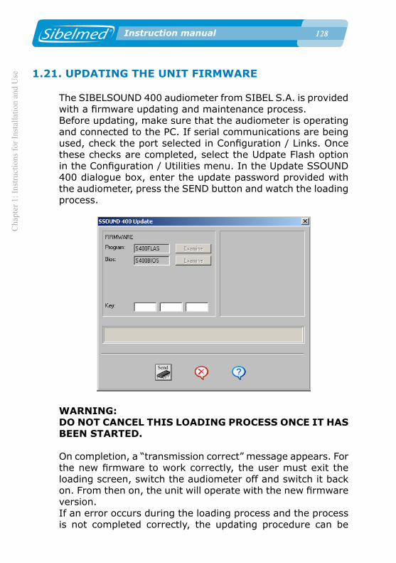
12� Instruction manual
Cha
pter
1: I
nstru
ctio
ns fo
r Ins
talla
tion
and
Use
12� Instruction manual
1.21. UPDATING THE UNIT FIRMWARE
The SIBELSOUND 400 audiometer from SIBEL S.A. is provided with a firmware updating and maintenance process. Before updating, make sure that the audiometer is operating and connected to the PC. If serial communications are being used, check the port selected in Configuration / Links. Once these checks are completed, select the Udpate Flash option in the Configuration / Utilities menu. In the Update SSOUND 400 dialogue box, enter the update password provided with the audiometer, press the SEND button and watch the loading process.
WARNING:DO NOT CANCEL THIS LOADING PROCESS ONCE IT HAS BEEN STARTED.
On completion, a “transmission correct” message appears. For the new firmware to work correctly, the user must exit the loading screen, switch the audiometer off and switch it back on. From then on, the unit will operate with the new firmware version. If an error occurs during the loading process and the process is not completed correctly, the updating procedure can be

Chapter 2: Technical Specifications
12� Instruction manual
repeated. To do so, exit the loading screen, switch off the audiometer and switch it back on. A screen should appear with the folowing text: ACT. FIRMWARE / UPDATE FIRMWARE. The procedure to update the audiometer firmware can now be repeated.
1.22. MAINTENANCE PROGRAM
The device has a maintenance program which allows it to adjust and/or check the functioning of certain options.A series of options grouped in the Equipment Test menu can be used to verify unit operation. From this menu it is possible to:
• Check the device hardware (CPU and LCD).• View the updating password and version of the equipment.• Test that the keyboard and the printer work properly.• Reset the device.
The options can be adjusted from three menus:
• Monitor: to adjust the volume of the monitor.• Speech-Inter: to adjust the volume of the technician microphone and headphones and the patient microphone.• Auxiliary: to adjust the volume of the auxiliary input.
To access it, turn the device on and press the key. Use the attenuators to select:
MENU3. MAINTENACE
TEST DEVICE
From the maintenance menu, use the attenuators to select the following options:
Press to access the various options:

1�0 Instruction manual
Cha
pter
2: T
echn
ical
Spe
cific
atio
ns
1�0 Instruction manual
MAINTENACE 1. TEST DEVIE
Press to access the various options:
CPU TEST
This option allows you to check the device's CPU. Use the attenuators to select the option:
TEST DEVICE1. CPU
Press to start the various CPU tests. When the tests are completed, the following screen appears:
RESTART TESTF1:YES F3:NO
Press to exit. In the event of errors, a message is
displayed for each error, scroll forward using the key. The previous screen is displayed again. If no errors have occurred, the device exits the CPU test.
LCD TEST
This option allows you to check the device's LCD. Use the attenuators to select the option:
TEST DEVICE2. LCD

Chapter 2: Technical Specifications
1�1 Instruction manual
Press to start each of the LCD tests or to exit.
TEST THE KEYBOARD
Select the option:
TEST DEVICE3. KEYBOARD
The test will request the user to press each of the keys on the keyboard.
To exit press the key for 1 second.
PRINTER TEST
Select the option:
TEST DEVICE4. PRINTER
This verifies that the printer is functioning correctly by printing out a test report.
UPDATING PASSWORD
Select the option:
TEST DEVICE5. UPDATE KEY
To view the password requested by the Audiometry W-50

1�2 Instruction manual
Cha
pter
2: T
echn
ical
Spe
cific
atio
ns
1�2 Instruction manual
software, it is necessary to load the device firmware again.
VERSION
Select the option:
TEST DEVICE6. VERSION
To view the Bios and Program version of the unit firmware.
RESET DEVICE
Select the option:
TEST DEVICE7. RESET DEVICE
The following screen appears:
RESET DEVICEF1:YES F3:NO
Press to reset the device.
Warning:THIS WILL ALSO RESULT IN THE LOSS OF BOTH USER AND STANDARD CONFIGURATION, WHICH WILL BE REPLACED BY THE DEFAULT FACTORY CONFIGURATION OF THE DEVICE.
MONITOR
The device has an optional module to monitor the signals

Chapter 2: Technical Specifications
1�� Instruction manual
applied to the patient, that also functions as an intercom.If the level of the monitor is set to 0, the monitor mode is deactivated and the module only operates as an intercom.The level of the monitor signal can be set between 1 and 10 (each unit corresponds to approximately 5.5 dB).For more convenient hearing, the monitor module adjusts the signal applied to the technician headphones at two levels, if the signal is too high the monitor automatically fades it and if it is too low the monitor amplifies it, so the signal is always within a comfortable hearing range.
Monitor mode:
To adjust the level of the monitor, select the following option:
MAINTANCE3. MONITOR
Place the technician headphones, apply the signal with the
o keys or use the attenuators to adjust the level of the monitor to the desired setting. To deactivate the monitor function, adjust the setting to 0.
SPEECH-INTER
This menu is used to adjust the level of the devices used in the Speech test and the intercom function (both optional).
These devices are:

1�� Instruction manual
Cha
pter
2: T
echn
ical
Spe
cific
atio
ns
1�� Instruction manual
• Technician headphones• Technician microphone• Patient microphoneIntercom mode:
To adjust these levels, select the following option:
MAINTANCE4. SPEECH-INTER
Apply the signal using the o keys and use the attenuators to adjust the level of the devices to the desired
setting. To change the device, press the o .
AUXILIARY
This menu is used to adjust the level of the auxiliary signal that can be used in the Speech test (optional). To adjust the level, select the following option:
MAINTANCE5. AUXILIAR
Apply the signal using the keys o and use the attenuators to adjust the level of the auxiliary signal.
The following table shows the signal flow and the adjustment options of the previous menus:

Chapter 2: Technical Specifications
1�� Instruction manual
Option to adjust Signal flowPatient headphones
Technician headphones
Monitor volume 1Khz dB tone selected 1Khz dB tone selected
Auxiliary volume Auxiliary signal Silence
Technician headphones Silence Patient microphone
Technician microphone Technician microphone Silence
Patient Microphone Silence Patient microphone
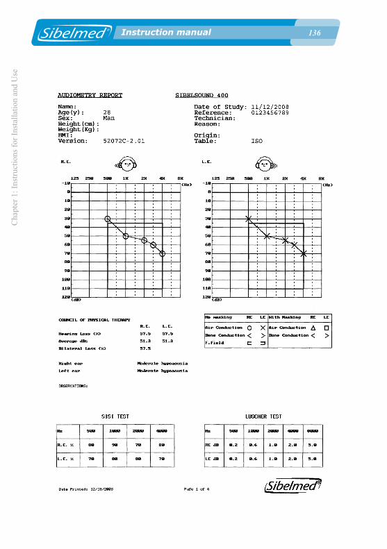
1�� Instruction manual
Cha
pter
1: I
nstru
ctio
ns fo
r Ins
talla
tion
and
Use
1�� Instruction manual

Chapter 1: Instructions for Installation and U
se
1�� Instruction manual
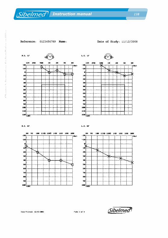
1�� Instruction manual
Cha
pter
1: I
nstru
ctio
ns fo
r Ins
talla
tion
and
Use
1�� Instruction manual

Chapter 2: Technical Specifications
1�� Instruction manual

1�0 Instruction manual
Cha
pter
2: T
echn
ical
Spe
cific
atio
ns
1�0 Instruction manual
Chapter 2: Technical Specifications
1�1 Instruction manual
2. TECHNICAL SPECIFICATIONS

1�2 Instruction manual
Cha
pter
2: T
echn
ical
Spe
cific
atio
ns
1�2 Instruction manual
As described in chapter 1 of the INSTRUCTIONS FOR INSTALLATION AND USE, there are six different models of the SIBELSOUND 400 and they can each be enhanced with options not installed as standard. Therefore, the technical specifications set out below correspond to a device which has all the available options.In each case, please bear in mind the configuration of your audiometer and the components which are not included.
2.1 TYPES OF TESTS
TONE AUDIOMETRY• Air conduction without masking• Bone conduction without masking• Air conduction with masking• Bone conduction with masking• Screening audiometry• Free field
SISI TESTSPEECH AUDIOMETRYFOWLERTONE DECAYLUSCHERWEBERPURE TONE HFFREE AUDIOMETRY
• Multiple tests or variants, depending on the specifications of the device (WARBLE, STENGER, etc.)• Free field audiometry
2.2. SIGNAL GENERATORS
TWO INDEPENDENT CHANNELS
• Right ear• Left ear

Chapter 2: Technical Specifications
1�� Instruction manual
ROUTES OF APPLICATION OF THE SIGNAL
• Air conduction (LF and HF)• Bone conduction• Free field• Monitor/Intercom
SIGNAL SOURCES • Pure tones LF Frequency: 125, 250, 500, 750, 1000, 1500, 2000, 3000, 4000, 6000 , 8000 Hz Accuracy: 1%
HF Frequency: 125, 250, 500, 750, 1000, 1500, 2000, 3000, 4000, 6000, 8000, 9000, 10000, 11200, 12500, 14000, 16000, 18000, 20000 Hz Accuracy: 1%
• Narrow band noise (NBN) for masking Band: In accordance with EN 60645-1 Out of band attenuation: Equal to or greater than 12 dB/octave
• Speech noise (SN) for masking Band: 125 Hz to 8000 Hz +- 3dB Out of band attenuation: 12 dB/octave
• White Noise (WN) for masking Band: 125 - 20000 Hz +- 3 dB
• Frequency modulation (FM) Carrier frequency: Pure tones Modulation frequency: 5 Hz ±1% Percentage modulation: +5%
• Speech audiometry Range: Variable Inputs: . Electret microphone

1�� Instruction manual
Cha
pter
2: T
echn
ical
Spe
cific
atio
ns
1�� Instruction manual
. Auxiliary input 200 mV, 50KOhms (Stereo 2 channels) for CD, etc. Level meter: Indicator on LCD Display.
MODES OF PRESENTATION OF THE SIGNALS
• Continuous
• Pulsating in all sources In accordance with EN-60645-1 Frequency: 2 Hz (50 ms signal rise, 200 ms signal, 50 ms signal fall and 200 ms silence) Accuracy: 3%
• SISI test Presentation of increases: Manual or automatic Level of increases: 1, 2, 3, 4 or 5 dB Presentation in automatic mode: Every 1, 2, 3, 4, 5, 6, 7, 8 or 9 seconds Duration of increase: 50 ms signal rise, 200 ms signal and 50 ms signal fall Accuracy: 3%
• Alternated pulse As per EN-60645-1 the same characteristics as the above but alternating between the right and the left channels.
• Range modulation Frequency: 2.5 Hz ±1% Range modulation: 0.2, 0.3, 0.4, 0.5, 0.6, 0.8, 1, 2, 3, 4 or 5 dB. Rise and fall time: 50 ms Level meter: Indicator on LCD Display. Accuracy: 3%
• Alternated modulation The same characteristics as the above but alternating between the right and the left channels.

Chapter 2: Technical Specifications
1�� Instruction manual
2.3. CONTROL OF SIGNAL LEVELS
MAXIMUM SIGNAL LEVELSHz 125 250 500 750 1000 1500 2000 3000 4000 6000 8000
Max dB HL 80 100 120 120 120 120 120 120 120 110 110
Min. dB HL -10 -10 -10 -10 -10 -10 -10 -10 -10 -10 -10
MAXIMUM HF SIGNAL LEVELSHz 125 250 500 750 1000 1500 2000 3000 4000 6000 8000
Máx dB HL 60 90 110 110 110 110 110 100 100 100 90
Mín. dB HL -20 -20 -20 -20 -20 -20 -20 -20 -20 -20 -20
Hz 9000 10000 11200 12500 14000 16000 18000 20000
Máx dB HL 90 90 90 50 50 50 50 50
Mín. dB HL -20 -20 -20 -20 -20 -20 -20 -20
MAXIMUM LEVELS OF MASKING SIGNALHz 125 250 500 750 1000 1500 2000 3000 4000 6000 8000
Max dB HL 60 80 100 100 100 100 100 100 100 100 90
Min. dB HL -10 -10 -10 -10 -10 -10 -10 -10 -10 -10 -10
MAXIMUM LEVELS OF HF MASKING SIGNALHz 125 250 500 750 1000 1500 2000 3000 4000 6000 8000
Máx dB HL 60 80 100 100 100 100 100 100 100 100 80
Mín. dB HL -20 -20 -20 -20 -20 -20 -20 -20 -20 -20 -20
Hz 9000 10000 11200 12500 14000 16000 18000 20000
Máx dB HL 80 80 80 40 40 40 40 40
Mín. dB HL -20 -20 -20 -20 -20 -20 -20 -20
MINIMUM SIGNAL LEVELS• -10 dB HL 125 to 8000 Hz• -20 dB HL 125 to 20000 Hz by air HF conduction

1�� Instruction manual
Cha
pter
2: T
echn
ical
Spe
cific
atio
ns
1�� Instruction manual
INCREASES IN SIGNAL LEVEL• Jumps of 5 dB ±1 dB• Jumps of 1 dB (Reference tone)
ACCURACY OF THE SIGNAL LEVELS• Accuracy: ±2 dB
INTERRUPTION OF THE TONE• Independent for each channel• Modes "direct" (there is signal on pressing) "inverted" (there is signal without pressing)• Attenuation: > 80 dB• Rise and fall time: 50 ms
2.4. OTHER FUNCTIONS
PERSONALISED FUNCTION CONFIGURATIONPRESENTATION OF FUNCTION STATUS
• Independent for each channel• Alphanumerical LCD display with 2x16 characters
INTERCOM
• Between operator and patient• Adjusts the level of signal
MEMORY
• Type: SDRAM• Capacity: more than 1000 aerial and bone tone tests in both channels at frequencies of 500,1000,2000,3000 y 4000 Hz

Chapter 2: Technical Specifications
1�� Instruction manual
OUTPUTS
• Parallel printer Centronics/USB• Serial port RS-232C/USB
2.5. TRANSDUCERS
AIR CONDUCTION LOW FREQUENCY• Headset TDH39 (pair) Telephonics
AIR CONDUCTION HIGH FREQUENCY• HDA 200 Sennheiser
BONE CONDUCTION• Vibrator B71
FREE FIELD• Loudspeakers with integrated amplifier
SPEECH AUDIOMETRY MICROPHONE• Electret type
2.6. APPLICABLE STANDARDS
ELECTRICAL SAFETY
• EN60601-1 Seg. medical equipment: Class 1 type B• EN60601-1-1 Seg. medical equipment• EN60601-1-4 Programmable systems
EMC
• EN60601-1-2 EMC in medical equipment (Not vital support) -EN 55011 RF Emissions (Group 1 type B) -EN 61000-3-2 Type A harmonic emissions

1�� Instruction manual
Cha
pter
2: T
echn
ical
Spe
cific
atio
ns
1�� Instruction manual
-EN 61000-3-3 Flicker emissions -EN 61000-4-2 ESD discharge (+- 6kV contact, +- 8KV air) -EN 61000-4-3 Radiated RF Immunity at 3V / m -EN 61000-4-4 BURST (+-2kV power, +-1KV input/output lines) -EN 61000-4-5 SURGE (+-1kV differential mode, +- 2KV common mode) -EN 61000-4-6 Conducted RF Immunity at 3 V rms -EN 61000-4-8 Magnetic field immunity at 3 A/m -EN 61000-4-11 Immunity to voltage dips
AUDIOMETERS
• EN 60645-1:2001 Pure tone audiometers• EN 60645.2:1993 Speech audiometers• High frequency tone audiometry in accordance with EN 60645-4
CALIBRATION
• EN ISO 389-1:2001 Air conduction• EN ISO 389-3:1999 Bone conduction• EN ISO 389-4:1999 Narrow band noise• EN ISO 389-5: 2000 High Frequency• EN ISO 389-7: 1998 Free Field and Diffuse Field
AUDIOMETRY
• Preliminary audiometry in accordance with EN ISO8253-1• Audiogram in accordance with recommendations in EN 26189:1991 (ISO6189:1983)• Speech audiometry in accordance with UNE-EN ISO8253-2

Chapter 2: Technical Specifications
1�� Instruction manual
2.7. GENERAL DATA
FUNCTION CONTROL
• Microprocessor type DSP• Access: Silicon keyboard• Display: LCD screen
Ambient Conditions
• Storage temperature: 0 to 60 °C• Working temperature: 10 to 40 °C• Relative humidity < 90% (no condensation)
POWER SUPPLY
• 90V-264V - 50/60Hz ±3%
POWER• < 50 VA
DIMENSIONS
• Width: 390 mm• Depth: 260 mm• Height: 105 mm
WEIGHT
• 2.4 Kg without accessories

1�0 Instruction manual
Cha
pter
2: T
echn
ical
Spe
cific
atio
ns
1�0 Instruction manual
Chapter 2: Technical Specifications
1�1 Instruction manual
3. OPERATING PRINCIPLES
1�2 Instruction manual
Cha
pter
3: O
pera
ting
Prin
cipl
es
1�2 Instruction manual
To carry out evaluations of physiological capabilities with electronic devices, we need to reproduce the physical conditions which can stimulate and produce the physiological responses to be evaluated.
In the case of the SIBELSOUND 400 audiometer, this involves reproducing defined sounds which when applied at calibrated and standardised levels obtain responses indicative of the capabilities of the auditor.
The electronic circuits incorporated in the Audiometer for this purpose are described below. As an aid to understanding, the block diagrams are shown in the Figure below:

Chapter 3: O
perating Principles
1�� Instruction manualA A
B B
C C
D D
E E
44
33
22
11
+1.2
6V
+3.3
V
+5V
Ais
lada
+5V
+12V
+3.3
V
+5V
-12V
-5V
Title
Siz
eD
ocum
ent N
umbe
rR
ev
Dat
e:S
heet
of
520-
725-
010
0
Dia
gram
a de
Blo
ques
Aud
iom
etro
/ B
lock
dia
gram
aud
iom
eter
SIB
EL
S.A
.: A
UD
IOM
ETR
O S
IBE
LSO
UN
D 4
00 /
SIB
ELS
OU
ND
400
AU
DIO
ME
TER
RE
ALI
ZAD
O /
DO
NE
: FR
AN
CIS
CO
A. S
OP
EN
AR
EV
ISA
DO
/ R
EV
ISE
D:
AN
TON
I PIC
OA
PR
OB
AD
O /
AP
RO
VE
D: J
.MA
RIA
PLA
NA
A4
11
Fuente de Alimentación / Power Supply
-5V
+5V
+3.3V
+12V+
-12V
Analog.
Digital
Módulo RS232/ RS232 Module
Modulo Monitor / Monitor Module
0,7A
0,25A
0,3A
0,2A
0,3A
Test
ADS7830
Micro Dr Int.
Int Tec Micro
Addr = 2:0004 -
2:2005
PC
Aerea Izq BF
left air LF
Selector vías
Route selector
A1 B1 A2 B2
Amplificador
Amplifier
LM1877
Codec
DSP
5502
Fuente Alimentación
RS232
MAX3222
CA Izq
Left F. Field
Osea
Bone
CA Der
Right F. Field
Aerea Der AF
Right air HF
USB
ISP1362
Aux (L+R)
Micro Dr Ext.
Ext Tec Micro
Digital: 5, 1.26, 3.3
Analog: 5, -5, 3.3
Aerea Izq AF
right air HF
Aerea Der BF
Right air LF
CPLD
CPLD
Pulsador
Pulsator
Teclado
Keyboard
Encoder
Fallos
failures
LCD Izq/left
LCD Der./right
Impresora Ext.
Ext. printer
+12,+5,+3.3,+1.26
Intercom/Monitor
TPA0172
RAM
MT48LC4M16A2P-75
1MB x 16 X 4
I2C
Contraste /Contrast
LCD ALF AD5247
RTC
M41ST85W
FLASH
M29W160EB70N6
1MB x 16
Cascos Dr.
Tec. Headphones
Micro Paciente
Patient micro
POTE
AD5242
Addr = 110 11 0 0
Fuente / Power
110-220 -> 12V
POTE
AD5242
XC9572XL
10TQ100C
XC9572XL
10TQ100C
Amplificador
Amplifier
MUX
Addr = 110 1000
Addr = 100 10 A1 A0
Addr = 010 1110
Addr = 010 11 0 1
Addr = 010 11 0 0
Addr = 011 010 A0
20:0000
40:0000
SPI
LCD 2X16
AC162 AMPIRE
Addr = 2:0008 -
2:200B
Addr = 2:0000 -
2:0003
+5V
+1.26V
FA -12V
FA -12V
MUX
Atenuador
Attenuator
Power supply
Amplificador
Amplifier
LM1877
Amplificador
Amplifier
LM1877

1�� Instruction manual
Cha
pter
3: O
pera
ting
Prin
cipl
es
1�� Instruction manual
3.1. RIGHT / LEFT CHANNEL
The left Channel consists of a set of circuits that process the signal received from the Codec and direct it to the headset of the left Air Conduction channel, the Vibrator for Bone Conduction or the Free Field left channel output.
MODULATOR
This equipment produces digital signal modulations using DSP.
ATTENUATOR
The attenuator is divided into three stages. One is in the DSP, another forms part of the Audio Codec (this circuit also incorporates a mute function with attenuation greater than 80 dB) and a final third stage located at the output to the Codec.
SIGNAL INTERRUPTION - SILENCER
Connection and disconnection of the signal is carried out digitally by putting the Codec into Mute mode. This component can effect switches with 50 ms transitions in accordance with Standards.
SOURCE SELECTOR
This selects between the various inputs - doctor's microphone, auxiliary input and the signals generated by the equipment. This consists of an analog selector controlled by the DSP.

Chapter 3: O
perating Principles
1�� Instruction manual
ROUTE SELECTOR
Two analog selectors direct the signal either to the amplifier for Right Air Conduction channel, (LF y HF) or the amplifier for Bone conduction or the Free Field output, depending on the code received from the Processor.
AMPLIFIER
The Amplifier consists of several power amplifiers (LF, HF and Bone) which operate directly on the patient's headphones or vibrator
3.2. MICROPROCESSOR
PHYSICAL DESCRIPTION
The DSP set consists of a series of electronic devices which store, process, receive and send information.
Very broadly, it is divided into:
• DSP processor unit
• Governing program residing in 2MB FLASH memory, (1Mb= 1024 Kbytes)
• 4 MB SDRAM Memory for storage of variables and execution of the program.
• Peripheral components.
PROGRAM
The governing program is developed in C language in order to achieve fast execution speeds. It processes all the signals that control the peripherals, read the keyboard, establish a link protocol via the USB and RS channels, process output to an external printer (USB or Centronics Parallel).

1�� Instruction manual
Cha
pter
3: O
pera
ting
Prin
cipl
es
1�� Instruction manual
DRAM MEMORY
This memory executes the audiometer control program and stores the variables used by the program, as well as other variables which define the status of the audiometer.
FLASH MEMORY
This type of memory allows a program and variables to be stored without the need for any external power.
DSP
This device carries out and processes the instructions contained in the program. It uses a TMS5502 with a clock frequency of 12 Mhz.
CODEC
This component has an internal 24-bit AD converter and generates all of the Audiometer's signals. It also controls the level of the signal and the silencer.
PERIPHERALS
The DSP communicates with the environment via several SPI buses, I2C and parallel.
CPLD
These are programmable logic devices. One of these controls the keyboard signals and the other is responsible for the LCD.

Chapter 3: O
perating Principles
1�� Instruction manual
RTC
This component provides us with the current date and time. It is powered by a long life lithium battery to maintain status information even when the device is turned off.
USB CONTROLLER
This component supports communications over the USB channel and also controls a USB printer.
3.3. INTERCOM (Optional)
The Intercom consists of an internally connected module which enables the patient to be listened in on by the Monitor, when they are in an audiometric booth or in a separate room from the Audiometer. The signal coming from the patient's microphone is controlled by means of a digital potentiometer and is power amplified directly to the doctor's headphones.
The intercom mode is used for the patient to be heard by the technician
The monitor mode allows the technician to monitor the signals applied to the patient. For more convenient hearing, the monitor module adjusts the signal applied to the technician headphones at two levels, if the signal is too high the monitor automatically fades it and if it is too low the monitor amplifies it, so the signal is always within a comfortable hearing range
3.4. FREE FIELD (Optional)
Free Field audiometry requires equipment to take the place of the patient headphones. The signals coming from the Audiometer are applied, by means of a connection, to the inputs of a set of power amplifiers which cause vibrations in

1�� Instruction manual
Cha
pter
3: O
pera
ting
Prin
cipl
es
1�� Instruction manual
two loudspeakers, located a certain distance from the patient. Free field calibration is carried out at a distance of 1 m from the loudspeaker at the centre of the axis along which the patient is seated. The ear of the patient and the centre of the loudspeaker must occupy the same horizontal plane. The amplifiers are powered directly from the mains and no controls are provided, with the exception of the ON / OFF switch and the on indicator light.

Chapter 4: A
udiometry Function
1�� Instruction manual
4. AUDIOMETRY TECHNIQUE

1�0 Instruction manual
Cha
pter
4: A
udio
met
ry F
unct
ion
1�0 Instruction manual
Audiometric techniques are very numerous due to the large number of variants which exist. Describing all of them would be a complex undertaking and beyond the scope of this manual.
However, it is entirely appropriate to follow the recommendations of standard EN 26189 (ISO 6189) regarding the performance of audiometry for the purpose of preserving hearing; the ISO 8253-1 standard regarding audiometry for the purpose of determining hearing thresholds; and ISO 8253-3 standard for carrying out speech audiometry.
Therefore, those specialists who require further information should refer to the many bibliographies which have been published on the subject.

Chapter 5: U
pkeep, preventive and corrective maintenance
1�1 Instruction manual
5. UPKEEP, PREVENTIVE AND CORRECTIVE MAINTENANCE

1�2 Instruction manual
Cha
pter
5: U
pkee
p, p
reve
ntiv
e an
d co
rrec
tive
mai
nten
ance
1�2 Instruction manual
As with any equipment, and in particular for medical applications, the SIBELSOUND 400 requires upkeep and maintenance, primarily in the interest of patient, operator and environmental safety, and secondly to ensure the reliability and accuracy of the functions for which it has been developed. This involves a series of routines which need to be carried out.
5.1. UPKEEP
Upkeep is the set of actions involved in keeping the equipment functioning correctly. The person who carries them out does not require any special technical knowledge other than their own understanding of the functioning and handling of the equipment. It is usually done by the normal user of the equipment. The procedures to be carried out are as follow:
CLEANING THE AUDIOMETER
The audiometer should be cleaned gently with a cloth moistened with water and dishwasher detergent. It can then be wiped dry. Take particular care to ensure that no liquid enters the interior of the device or the connectors and connections.Do not use abrasive substances or solvents.
CLEANING THE ACCESSORIES
Care of the accessories follows the same method as described above for the device itself.
The earpads for the air conduction headphones can be cleaned more thoroughly if first detached from the headset, washed with water and soap and then dried completely with a cloth before reattaching to the headset.

Chapter 5: U
pkeep, preventive and corrective maintenance
1�� Instruction manual
WARNING:THE BONE CONDUCTION VIBRATOR IS A VERY FRAGILE COMPONENT, AND EVEN SMALL IMPACTS CAN LEAD TO A DETERIORATION IN ITS CHARACTERISTICS. THEREFORE, YOU ARE ADVISED TO HANDLE IT WITH GREAT CARE.
5.2. PREVENTIVE MAINTENANCE
Preventive maintenance consists of all actions carried out for the purpose of keeping the equipment in perfect working order.
Various guidelines can be established, although there certain standards, such as EN 8253-1 and ISO 26189 that are the most appropriate. The method to follow is at the discretion of the specialist, although as a minimum we recommend the following:
ROUTINE CHECKS AND SUBJECTIVE TESTS
This check is to be carried out weekly and the process is as follows:
1 Check that the connections are all correctly attached, and that there is no sign of cracking or external damage to the cables and/or connectors, or to any other component.
2 Carry out a subjective test to ensure that the audiometer output, via both air conduction and bone conduction, is the same in both channels and for all frequencies. To do this, use a level of 10 or 15 dB, above the hearing threshold. The person carrying out the subjective tests should have normal hearing.
3 Check at a level of 60 dB in air conduction and 40 in bone

1�� Instruction manual
Cha
pter
5: U
pkee
p, p
reve
ntiv
e an
d co
rrec
tive
mai
nten
ance
1�� Instruction manual
conduction that there is no distortion discernible in any of the frequencies, and no noise or interference signals, etc.
4 Check that the signal key works correctly in both direct and inverted modes.
5 Check that the attenuator levels work correctly with no noise or interference between channels.
6 Check the speech audiometry and intercom channel.
7 Check that the attachment bands for the headset and vibrator are in good condition.
OBJECTIVE CHECK
The check consists of a general technical verification of the safety systems, adjustments, functions, calibrations, etc. involved in the configuration of the equipment.
The calibration is carried out with the aid of an artificial ear and mastoids in accordance with applicable standards.
THESE CHECKS MUST BE CARRIED OUT AT LEAST ANNUALLY and in accordance with the Checking and Adjustment Procedure for the SIBELSOUND 400 audiometer, available from the manufacturer. Procedures of this kind must be carried out by qualified technical personnel from the medical centre's maintenance department, or from the distributor's or manufacturer's technical service department.
In any event, SIBEL S.A. as manufacturer, must provide authorisation in writing, at least during the warranty period to the relevant technical service so that they can carry out the above-mentioned maintenance and in no case accepts responsibility for any damage, malfunction, etc. which may arise as a consequence of defective maintenance by persons not employed by SIBEL S.A.

Chapter 5: U
pkeep, preventive and corrective maintenance
1�� Instruction manual
5.3. CORRECTIVE MAINTENANCE
Corrective maintenance involves returning to good working order equipment which no longer functions due to incorrect operation or handling and is in need of repair.
On detecting any fault with equipment which interferes with its normal use, disconnect the equipment from the mains and contact SIBEL S.A. Aftersales Service, explaining the problem in as much detail as possible.
If the equipment requires corrective maintenance, it is advisable to also carry out the preventive maintenance described in the section OBJECTIVE CHECK.
This requirement should be communicated to the technical service carrying out the repair, since certain faults may involve misalignments that are not readily detectable without in depth review and calibration.

1�� Instruction manual
Cha
pter
5: U
pkee
p, p
reve
ntiv
e an
d co
rrec
tive
mai
nten
ance
1�� Instruction manual
Chapter 6: M
odifications
1�� Instruction manual
6. MODIFICATIONS

1�� Instruction manual
Cha
pter
6: M
odifi
catio
ns
1�� Instruction manual

Appendix 1: Electrom
agnetic compatibility
1�� Instruction manual
APPENDIX 1
ELECTROMAGNETIC COMPATIBILITY

1�0 Instruction manual
Cha
pter
8: U
pkee
p, p
reve
ntiv
e an
d co
rrec
tive
mai
nten
ance
1�0 Instruction manual
Guide and statement from the manufacturer - electromagnetic emissions
The Sibelsound 400 is designed to be used in the electromagnetic environment specified below. The customer or user must ensure that it is used in such an environment.
Emissions Test Levelof compliance
Guide – Electromagnetic Environment
Radiated RF Emissions
CISPR 11 (EN 55011)
Group 1
Conducted RF Emissions
CISPR 11 (EN 55011)
Class B
Harmonic Emissions
EN-IEC 61000-3-2
Class B
Voltage flicker and fluctuations
EN-IEC 61000-3-3
Class B
The Sibelsound 400 uses RF energy only for internal use. Therefore, its emissions are very low and i t is unl ikely to cause interference to surrounding electronic devices.
In order to function, the Sibelsound 400 must be connected to the electrical mains.
In order to function, the Sibelsound 400 must be connected to the electrical mains.
In order to function, the Sibelsound 400 must be connected to the electrical mains.

Appendix 1: Electrom
agnetic compatibility
1�1 Instruction manual
Manufacturer guide and statement – electromagnetic immunity
The Sibelsound 400 is designed to be used in the electromagnetic environment specified below. The customer or user of the Sibelsound 400 must ensure that it is used in such an environment.
Immunity Test Test level for EN IEC 60601
Level of compliance
Guide – Electromagnetic Environment
ElectrostaticDischarge (ESD)
EN-IEC 61000-4-2
±6 kV in contact
±8 kV in air
±6 kV in contact
±8 kV in air
Electrical Fast Transient/Burst
EN-IEC 61000-4-4
±2 kV for power lines and earth
±1 kV for input/output lines
±2 kV for power lines and earth
±1 kV for input/output lines
Shock waves (Surge)
EN-IEC 61000-4-5
±1 kV in differential mode
±2 kV in common mode
±1 kV in differential mode
±2 kV in common mode
Voltage Dips, Short Interruptions and Voltage Variations
EN-IEC 61000-4-11
<5 % Ut(>95 % fall in Ut) for 0.5 cycles40 % Ut(60 % fall in Ut) for 5 cycles70 % Ut(30 % fall in Ut) for 25 cycles<95 % Ut(>5 % fall in Ut) for 5 seconds
<5 % Ut(>95 % fall in Ut) for 0.5 cycles40 % Ut(60 % fall in Ut) for 5 cycles70 % Ut(30 % fall in Ut) for 25 cycles<95 % Ut(>5 % fall in Ut) for 5 seconds
Magnetic field 50 / 60 Hz
EN-IEC 61000-4-8
3 A/m 3 A/m
T h e f l o o r m u s t b e m a d e o f wood, cement or ceramic tiles If t h e f l o o r i s c o v e r e d i n a synthetic material, the relative humidity must be at lest 30 %.
The length of I/O l ines is less than 3 m.
The magnetic f ield in the room must be low enough to ensure the test can be carried out.
Note that Ut is the alternating current power supply expected for the purposes of the test.

1�2 Instruction manual
App
endi
x 1:
Ele
ctro
mag
netic
com
patib
ility
1�2 Instruction manual
Manufacturer guide and statement – electromagnetic immunity
All models of the DEVICE are designed to be used in the electromagnetic environment specified below. The customer or user of the SBELHOME Plus must ensure that it is used in such an environment.
Immunity Test EN-IEC 60601 test level Level of compliance
Guide – Electromagnetic Environment
Conducted RF
EN-IEC 61000-4-6
3 Vrms
from 150 kHz to 80 MHz
3 VrmsPd =[ ]
35.3
Radiated RF
EN-IEC 61000-4-3
3 V/m
from 80 MHz to 2.5 GHz
3 V/mPd =[ ]
35.3
from 80 MHz to 800 MHz
Pd =[ ]37
from 800 MHz to 2.5 GHz
Note 1 At 80 MHz and 800 MHz, apply the higher frequency margin
Note 2 These recommendations may not apply in all possible situations. Electromagnetic propagation can be affected by absorption and reflection by structures, objects and persons.
Portable and mobile RF communication equipment must not be used closer to any part of the SIBEL-HOMEPlus, including cables, than the recommended separa-tion distance calculated from the equation applicable to the frequency of the transmitter.
Recommended separation distance
Where P is the transmitter's maximum output power in Watts (W) according to the manufacturer and d is the recommended separation distance in metres (m).
Field intensities emerging from fixed RF transmitters, determined by electromagnetic measurement at location a, must be less than the compliant level at each frequency margin b.
Interference can arise in the proximity of equipment marked with the following symbol:
a The exact field intensities emitted by fixed transmitters, such as radiotelephone base stations (wireless cellular-mobile phones) and mobile radios, radio hams, AM, FM and TV radio broadcasts, cannot be theoretically calculated. To determine the electromagnetic environment due to fixed transmitters, consider carrying out electromagnetic measurements in the area of use.In the event that the field intensity in the area of use is greater than the compliant level, check whether the behaviour of the DEVICE is normal. If not, it may be necessary to take additional measures such as the reorientation or relocation of the DEVICE.
b Above the 150 kHz to 80 MHz frequency range, the field intensity must be less than 3 V/m.

Appendix 1: Electrom
agnetic compatibility
1�� Instruction manual
Recommended separation distances between mobile and portable RF communication equipment and the Sibelsound 400
Separation distance as a function of the transmitter frequencyMaximum output power of the transmitterW From 80 MHz to 800 MHz
Pd =[ ]35.3
From 800 MHz to 2.5 GHz
Pd =[ ]37
0.01 0.12 0.23
0.1 0.37 0.74
1 1.17 2.33
10 3.69 7.38
100 11.67 23.33
For transmitters with a maximum output power not listed above, the recommended separa-tion distance d in metres (m) can be estimated using the relevant equation according to the frequency of the transmitter, where P is the maximum power of the transmitter in Watts (W) according to the manufacturer.
Note 1 At 800 MHz, apply the higher frequency margin
Note 2 These recommendations may not apply in all possible situations. Electromagnetic propagation can be affected by absorption and reflection by structures, objects and persons.
The Sibelsound 400 is designed to be used in an electromagnetic environment in which radiated RF perturbations are controlled. The customer or user of the Sibelsound 400 can help to prevent interference by maintaining a minimum distance between mobile and portable RF communications equipment (transmitters) and the Sibelsound 400 as recommended below, according to the output power of the communications equipment.

1�� Instruction manual
App
endi
x 2:
Com
plia
nce
with
the
Org
anic
Law
on
Dat
a Pr
otec
tion
1�� Instruction manual

Appendix 2: C
ompliance w
ith the Organic Law
on Data Protection
1�� Instruction manual
APPENDIX 2
COMPLIANCE WITH THE DATA PROTECTION ACT. DIRECTIVE 95/46/EC
1�� Instruction manual
App
endi
x 2:
Com
plia
nce
with
the
Org
anic
Law
on
Dat
a Pr
otec
tion
1�� Instruction manual
COMPLIANCE WITH THE DATA PROTECTION ACT. DIRECTIVE 95/46/EC.
REQUIREMENTS SPECIFICALLY AFFECTING THE USE OF THE DATOSPIR MICRO SPIROMETER
This section seeks to ensure user compliance with the current data protection legislation in relation to the use of this equipment.A brief description is given as to how the SIBELSOUND 400 Audiometer must be handled to comply with the requirements of this act.
OTHER IMPORTANT ISSUES
• Printing documents:
In the event of saving paper printouts containing patient details, these documents must be properly stored so that only duly authorised personnel have access to them. Furthermore, in the event of users deciding to dispose of the printed documents, their effective physical destruction must be ensured to avoidunauthorised access thereto.
IMPORTANT WARNING
• According to current legislation, the user of this equip-
ment is the only party responsible for saving and processing
the details of his patients according to the Law.
• Observance of the recommendations included in this sec-
tion under no circumstances guarantees the full adaptation
of the user’s activity to the data protection regulation.

Appendix 2: C
ompliance w
ith the Organic Law
on Data Protection
1�� Instruction manual
• Data transmission:
The SIBELSOUND 400 audiometer can transmit files containing patient details via PC connection so that work can be subsequently carried out on them using the W50 Audioometry Software. This software is also compliant with the Data Protection Act, as explained in the W50 Audiometry Software User’s Manual.

1�� Instruction manual
App
endi
x 3:
Cal
cula
tion
tabl
es fo
r dia
gnos
es
1�� Instruction manual
APPENDIX 3
CALCULATION TABLES FOR DIAGNOSES

Appendix 3: C
alculation tables for diagnoses
1�� Instruction manual
1. “MINISTRY” DIAGNOSIS
The percentage of hearing loss is determined by the pure tone audiogram and according to the evaluation criteria for discapacity due to hearing deficiency as established by the Spanish Ministry of Labour and Social Affairs in OSB No. 22 of January 26, 2000.
A. Monoaural hearing loss
1. The hearing thresholds of each ear are determined at frequencies of 500, 1000, 2000 and 3000 Hz and added. NOTE: If one of the central frequencies is missing (1000 or 2000) and an adjacent frequency is selected, the audiometer uses this frequency to calculate the diagnosis and includes this modification in the report.
2. The corresponding hearing loss is found in Table 1.
3. If the hearing threshold is 25 dB or lower, this is not considered as loss of hearing.
Example:
Right ear (RE) 500 1000 2000 3000dB of loss 15 10 5 10Sum (15+10+5+10 = 40)
% Hearing loss RE 0.0 %dB Average RE (40/4) 10.0 dB
Left ear (LE) 500 1000 2000 3000dB of loss 35 30 40 50 Sum (35+30+40+50 = 155)
% Hearing loss RE 20.6 %dB Average LE (155/4) 38.7 dB
1�0 Instruction manual
App
endi
x 3:
Cal
cula
tion
tabl
es fo
r dia
gnos
es
1�0 Instruction manual
B. Binaural or Bilateral hearing loss
Binaural hearing loss is calculated by multiplying the loss of the best ear by five and adding the loss of the worst ear and then dividing the total by six.
Binaural hearing loss in % = (5x(% loss in best ear) + (% loss in worst ear))/6.
Example:
Binaural hearing loss % = (5x0.0 + 20.6)/6 = 3.4%
C. Categories of Hearing Loss
The MINISTRY diagnosis does not establish categories of hearing loss. However, professional clinical recommendations have led us to include the following categories depending on the hearing loss in each ear:
HEARING LOSS CATEGORIES. NORMAL 0 to 10% . SLIGHT HYPOACUSIA 11 to 30%. MODERATE HYPOACUSIA 31 to 60%. SEVERE HYPOACUSIA 61 to 100%

Appendix 3: C
alculation tables for diagnoses
1�1 Instruction manual
Table 1. CONVERSION OF THE ESTIMATED HEARING LEVEL IN PERCENTAGE OF MONOAURAL HEARING LOSS.
dshl,dB
%loss
dshl,dB
%loss
dshl,dB
%loss
dshl,dB
%loss
100 0.0 170 26.2 240 52.5 310 78.8
105 1.9 175 28.1 245 54.4 315 80.6
110 3.8 180 30.0 250 56.2 320 82.5
115 5.6 185 31.9 255 58.1 325 84.4
120 7.5 190 33.8 260 60.0 330 86.2
125 9.4 195 35.6 265 61.9 335 88.1
130 11.2 200 37.5 270 63.8 340 90.0
135 13.1 205 39.4 275 65.6 345 90.9
140 15.0 210 41.2 280 67.5 350 93.8
145 16.9 215 43.1 285 69.3 355 95.6
150 18.8 220 45.0 290 71.2 360 97.5
155 20.6 225 46.9 295 73.1 365 99.4
160 22.5 230 48.9 300 75.0 370 100.0
165 24.4 235 50.5 305 76.9

1�2 Instruction manual
App
endi
x 3:
Cal
cula
tion
tabl
es fo
r dia
gnos
es
1�2 Instruction manual
2. “COUNCIL” DIAGNOSIS
The percentage of hearing loss is determined from the pure tone audiogram in accordance with the second formula of the Council of Physical Therapy. A percentage of the hearing loss in each ear is taken at the 500, 1000, 2000 and 4000 Hz frequencies as a function of their importance, specifically 15% at 500 and 4000 Hz, 30% at 1000 Hz and 40% at 2000 Hz. A 0% hearing loss corresponds to normal and a 100% hearing loss to cofosis. By reference to a table published by the institution, you can find the percentage hearing loss for each frequency and the level of intensity.
A. Monoaural hearing loss
1. The hearing thresholds of each ear are determined at frequencies of 500, 1000, 2000 and 4000 Hz and added. 2. The corresponding percentage of hearing loss for each frequency and intensity is found in Table 2.3. The loss values for the four frequencies are added, giving the % of hearing loss of the ear under study.
Example:
Right ear (RE) 500 1000 2000 4000dB of loss 15 10 5 10% loss 0.5 0.3 0 0.1Sum (0.5+0.3+0+0.1 = 0.9)
% Hearing loss RE 0.9%dB Average RE (40/4) 10.0 dB
Left ear (LE) 500 1000 2000 4000dB of loss 35 30 40 50% loss 3.7 5.4 12.9 8.0Sum (3.7+5.4+12.9+8.0 = 30.0)
% Hearing loss LE 30.0%dB Average LE (155/4) 38.7 dB

Appendix 3: C
alculation tables for diagnoses
1�� Instruction manual
B. Binaural hearing loss
Binaural hearing loss is calculated by multiplying the loss of the best ear by seven and adding the loss of the worst ear and then dividing the total by eight. Binaural hearing loss in % = (7x(% loss in best ear) + (% loss in worst ear))/8.
Example:
Binaural hearing loss % = (7x0.9 + 30.0)/8 = 4.5%
C. Categories of Hearing Loss
The “COUNCIL” diagnosis does not establish categories of hearing loss. However, the same categories as for the “MINISTRY” diagnosis have been adopted.

1�� Instruction manual
App
endi
x 3:
Cal
cula
tion
tabl
es fo
r dia
gnos
es
1�� Instruction manual
Lossin dB
500 1000 2000 4000
5
10 0.2 0.3 0.4 0.1
15 0.5 0.9 1.3 0.3
20 1.1 2.1 2.9 0.9
25 1.8 3.6 4.9 1.7
30 2.6 5.4 7.3 2.7
35 3.7 7.7 9.8 3.8
40 4.9 10.2 12.9 5.0
45 6.3 13.0 17.3 6.4
50 7.9 15.7 22.4 8.0
55 9.6 19.0 25.7 9.7
60 11.3 21.5 28.0 11.2
65 12.8 23.5 30.2 12.5
70 13.8 25.5 32.2 13.5
75 14.6 27.2 34.4 14.2
80 14.8 28.8 35.8 14.6
85 14.9 29.8 37.5 14.8
90 15.0 29.9 39.2 14.9
95 15.0 30.0 40.0 15.0
100
Table 2. COUNCIL OF PHYSICAL THERAPY 2ª FÓRMULA

Appendix 3: C
alculation tables for diagnoses
1�� Instruction manual
3. DIAGNOSIS OF THE MEXICAN INSTITUTE OF SOCIAL SECURITY
The percentage of hearing loss is determined from the pure tone audiogram in accordance with the Mexican Social Security Institute.
A. Monoaural hearing loss
1. The hearing thresholds of each ear are determined at frequencies of 500, 1000, 2000 and 3000 Hz and added. 2. The four values of each ear are added and the average is calculated.3. The result is then multiplied by 0.8 (Fletcher Index).
Example:
Right ear (RE) 500 1000 2000 3000dB of loss 15 10 5 10 Average = (15+10+5+10)/4 = 10 dB
% Hearing Loss RE = 10 x 0.8 = 8%dB Average RE (40/4) 10.0 dB
Left ear (LE) 500 1000 2000 3000dB of loss 35 30 40 50Average = (35+30+40+50)/4 = 38.7 dB
% Hearing Loss LE = 38.7 x 0.8 = 31%dB Average LE (155/4) 38.7 dB
B. Binaural hearing loss
Binaural hearing loss is calculated by multiplying the loss of the best ear by seven and adding the loss of the worst ear and then dividing the total by eight.Binaural hearing loss in % = (7x(% loss in best ear) + (% loss in worst ear))/8.

1�� Instruction manual
App
endi
x 3:
Cal
cula
tion
tabl
es fo
r dia
gnos
es
1�� Instruction manual
Example:
Binaural hearing loss % = (7x8 + 31.0)/8 = 10.9 %
C. Categories of Hearing Loss
The “MEXICAN” diagnosis does not establish categories of hearing loss. However, the same categories as for the “MINISTRY” diagnosis have been adopted.
4. ELI
The ELI (Early Loss Index) is calculated from a frequency of 4000 Hz and following the tables of the Protocol for Specific Health Surveillance (Interterritorial Council of the Spanish National Health System) following the steps below:1. The ELI is calculated by subtracting the corresponding correction value for presbycusia in Table 3 from the hearing loss at a frequency of 4000 Hz. The frequency of 4000 Hz is evaluated (considering loss due to age and gender).2. Acoustic trauma is classified on an increasing scale of A-B-C-D-E, from lower to higher hearing capacity according to Table 4.
Example:
Patient: Male, 50 years oldRight ear (RE) 4000 dB of loss 30 Left ear (LE) 4000 dB of loss 40Applying correction, ELI
Right ear 30 – 20 = 10 dB --- Grade B Normal good Left ear 40 – 20 = 20 dB --- Grade C Normal
Table for ELI calculationCorrection for presbycusia at 4000 Hz dB
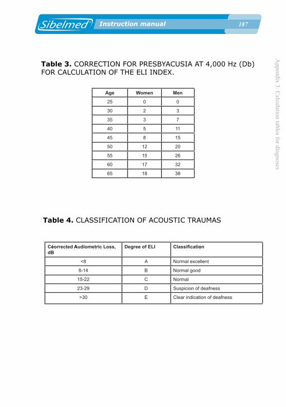
Appendix 3: C
alculation tables for diagnoses
1�� Instruction manual
Table 3. CORRECTION FOR PRESBYACUSIA AT 4,000 Hz (Db)FOR CALCULATION OF THE ELI INDEX.
Age Women Men
25 0 0
30 2 3
35 3 7
40 5 11
45 8 15
50 12 20
55 15 26
60 17 32
65 18 38
Table 4. CLASSIFICATION OF ACOUSTIC TRAUMAS
Céorrected Audiometric Loss, dB
Degree of ELI Classification
<8 A Normal excellent
8-14 B Normal good
15-22 C Normal
23-29 D Suspicion of deafness
>30 E Clear indication of deafness

1�� Instruction manual
App
endi
x 3:
Cal
cula
tion
tabl
es fo
r dia
gnos
es
1�� Instruction manual
5. SAL INDEX
The SAL Index (Speech Average Loss) evaluates the conversational frequencies (500, 1000 and 2000 Hz) and is defined as the arithmetic mean of hearing loss in decibels of these frequencies. It establishes a classification by degrees A-B-C-D-E-F-G from SAL-A (both ears are within normal limits) to SA-G (complete deafness).
Once this value has been obtained, Table 5 of the SAL Index is used to present the evaluation.
To arrive at the index, both ears need to be tested.
Clinical recommendations have led us to change the text of the SAL Index Table of the Protocol for Specific Health Surveillance (Interterritorial Council of the Spanish National Health System) according to the following:
Grade C changes from “Slightly worse” to “Slight Hearing Impairment” Grade D changes from “Seriously worse” to “Significant Hearing Impairment” Grade E changes from “Severely worse” to “Serious Hearing Impairment” Grade F changes from “Extremely worse” to “Severe Hearing Impairment”
Grade F covers 91 to 99 dB and Grade G applied to 100 dB onwards.
There are some situations not covered by the evaluation table, particularly where impairment is too asymmetric, (one ear within the normal range but the other however displays serious acoustic trauma). This occurs when the best ear presents a drop of <16 dB and the worst ear presents >30 dB. In such cases, the following text is displayed:“Detected deafness too asymmetric to be evaluated using the SAL table”.
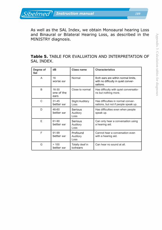
Appendix 3: C
alculation tables for diagnoses
1�� Instruction manual
Table 5. TABLE FOR EVALUATION AND INTERPRETATION OF SAL INDEX.
Degree of Sal
dB Class name Characteristics
A 16worse ear
Normal Both ears are within normal limits, with no difficulty in quiet conver-sations.
B 16-30one of the ears
Close to normal Has difficulty with quiet conversatio-ns but nothing more.
C 31-45better ear
Slight Auditory Loss
Has difficulties in normal conver-sations, but not if people speak up.
D 46-60better ear
SeriousAuditoryLoss
Has difficulties even when people speak up.
E 61-90better ear
SeriousAuditoryLoss
Can only hear a conversation using a hearing aid.
F 91-99better ear
ProfoundAuditoryLoss
Cannot hear a conversation even with a hearing aid.
G > 100better ear
Totally deaf in bothears
Can hear no sound at all.
As well as the SAL Index, we obtain Monoaural hearing Loss and Binaural or Bilateral Hearing Loss, as described in the MINISTRY diagnosis.

1�0 Instruction manual
App
endi
x 3:
Cal
cula
tion
tabl
es fo
r dia
gnos
es
1�0 Instruction manual
6. KLOCKHOOF DIAGNOSIS (MODIFIED BY THE LAVORO CLINIC OF MILAN)
For this test, the 500, 1000, 2000 and 4000 frequencies are investigated, and the criteria set out in Table 6 are applied:1. If the threshold is not higher than 25 dB at any frequency, the diagnosis is: “Normal”
2. If the threshold at the 4000 frequency is below 55 dB and below 25 dB in the other frequencies, the diagnosis is: “Slight Acoustic Trauma”“No conversational loss”
3. If the threshold at the 4000 frequency is above 55 dB and below 25 dB in the other frequencies, the diagnosis is: “Advanced Acoustic Trauma”“No conversational loss”
4. If there are 1 or more frequencies below 25 dB (at least one >25 dB) the diagnosis is: “Slight hypoacusia by noise”“Conversational loss”
5. If all the frequencies are affected but none is above 55 dB, the diagnosis is: “Moderate hypoacusia by noise”“Conversational loss”
6. If all the frequencies are affected and one or more are above 55 dB, the diagnosis is: “Advanced hypoacusia by noise”“Conversational loss”
(Diagram modified by the Lavoro Clinic of Milan)

Appendix 3: C
alculation tables for diagnoses
1�1 Instruction manual
Table 6. KLOCKHOFF CLASSIFICATION.
NORMAL The threshold does not exceed 25 dB at any frequency.
ISOLATEDACOUSTICTRAUMA
No conversatio-nal loss
LIGHTThe threshold at the 4000 frequen-cy is below 55 dB and below 25 dB in the other frequencies.
ADVANCEDThe threshold at the 4000 frequen-cy is above 55 dB and below 25 dB at the other frequencies.
GLOBALACOUSTIC TRAUMA
Conversational loss
LIGHT One or more frequencies are not affected (are below 25 dB).
MODERATE All frequencies are affected (above 25 dB) but none is above 55 dB.
ADVANCED All frequencies are affected (above 25 dB) and one above 55 dB
OTHER LOSS not due to exposure to sound.


![4001].pdf · pruebas tonales supraliminares. El audiómetro SIBELSOUND 400, ha sido desarrollado por el departamento de I+D+i de SIBEL, S.A. en colaboración](https://static.fdocuments.net/doc/165x107/5bc2b63c09d3f27d2f8da028/1pdf-pruebas-tonales-supraliminares-el-audiometro-sibelsound-400-ha-sido.jpg)