SI 3C LP - Extron Electronics€¦ · SI 3C LP Ceiling Speaker a. Remove the top terminal cover ......
3
Frame Construction Ceiling Installation 1 Take the cutout template from the packaging box and punch out along the larger perforated circle. Place the cutout template against the ceiling and trace along the inside circle. Carefully cut out the ceiling material along the circle. 3 Cut material. SI 3C LP Ceiling Speaker a. Remove the top terminal cover (see the illlustration in step 3f) by loosening (do not remove) both top screws, sliding the top terminal cover away from the screws, and removing the cover, as shown here. 68-1469-01 Rev. B 11 07 User’s Guide 2 The side terminal cover, as shown in step 3f, must first be removed before wiring the speaker. Loosen the single top screw of the side terminal cover and pull the side terminal cover straight out. See the illustration below. Side View of Input Terminal Top Terminal Cover Loosen screw. Loosen two screws. c. Insert the conduit(s) into the knockout opening(s) and secure the conduit to the cover with the locking nut. d. Pull the speaker wires from the conduit, strip 0.2" (5 mm) from the wire ends (do not tin the wires), and secure the wires into the 4-pole captive screw connector. To connect speakers in parallel, see the wiring diagram below. e. Bring the speaker up to the bottom of the hole in the ceiling. f. Plug the wired connector from step 3d into the speaker’s audio input connector. Secure the top terminal cover with the two top screws that were loosened in step 3a; hook the side terminal cover to the top terminal cover; and secure the side terminal cover in place with the screw that was loosened in step 2. 1 Power Amplifier Speaker 1 Speaker 2 Trace template. Side Terminal Cover N Installation in a plenum-rated environment requires a wire gauge of 14 AWG to 18 AWG. Top Terminal Cover Side Terminal Cover See NOTE below. b. Remove the knockout(s) from the top terminal cover depending on the direction from which the conduit(s) will be entering the cover. Front View of Input Terminal 4-pole Captive Screw Connector LOOP IN LOOP IN N Installation in a plenum-rated environment requires a wire gauge of 14 AWG to 18 AWG. Knockout 4-pole Captive Screw Connector
-
Upload
dangnguyet -
Category
Documents
-
view
219 -
download
0
Transcript of SI 3C LP - Extron Electronics€¦ · SI 3C LP Ceiling Speaker a. Remove the top terminal cover ......
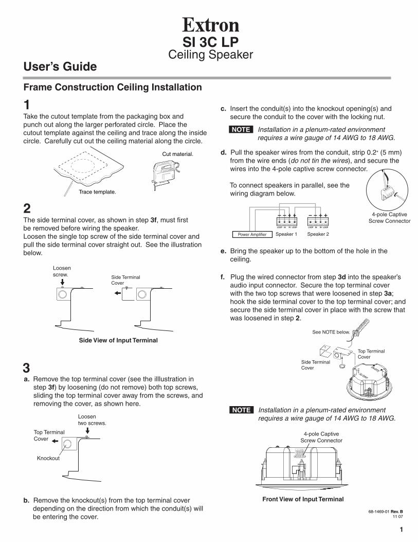
Frame Construction Ceiling Installation
1Take the cutout template from the packaging box andpunch out along the larger perforated circle. Place the cutout template against the ceiling and trace along the insidecircle. Carefully cut out the ceiling material along the circle.
3
Cut material.
SI 3C LPCeiling Speaker
a. Remove the top terminal cover (see the illlustration in step 3f) by loosening (do not remove) both top screws, sliding the top terminal cover away from the screws, and removing the cover, as shown here.
68-1469-01 Rev. B11 07
User’s Guide
2The side terminal cover, as shown in step 3f, must firstbe removed before wiring the speaker.Loosen the single top screw of the side terminal cover and pull the side terminal cover straight out. See the illustrationbelow.
Side View of Input Terminal
Top TerminalCover
Loosenscrew.
Loosentwo screws.
c. Insert the conduit(s) into the knockout opening(s) and secure the conduit to the cover with the locking nut.
d. Pull the speaker wires from the conduit, strip 0.2" (5 mm) from the wire ends (do not tin the wires), and secure the wires into the 4-pole captive screw connector. To connect speakers in parallel, see the wiring diagram below.
e. Bring the speaker up to the bottom of the hole in the ceiling.
f. Plug the wired connector from step 3d into the speaker’s audio input connector. Secure the top terminal cover with the two top screws that were loosened in step 3a; hook the side terminal cover to the top terminal cover; and secure the side terminal cover in place with the screw that was loosened in step 2.
1
Power Amplifier Speaker 1 Speaker 2
Trace template.
Side TerminalCover
N Installation in a plenum-rated environment requires a wire gauge of 14 AWG to 18 AWG.
Top TerminalCover
Side TerminalCover
See NOTE below.
b. Remove the knockout(s) from the top terminal cover depending on the direction from which the conduit(s) will be entering the cover.
Front View of Input Terminal
4-pole CaptiveScrew Connector
LOOP IN LOOPIN
33-1351-01R
ev. B
N Installation in a plenum-rated environment requires a wire gauge of 14 AWG to 18 AWG.
Knockout
4-pole CaptiveScrew Connector

L R
AUX/MIX IN
1B
1A
INPUTS
OUTPUTS
2B
2A
4
3
RS-232 MLC/IRDC VOL
4/8Ohms
AMPLIFIED OUTPUTS
VOL/MUTE
Tx
A B C
Rx IR 12V
10V
POWER
12V 3A MAX
USLISTED 17TT
AUDIO/VIDEOAPPARATUS
®
RGB VIDEO RGB
VIDEO
STEREOON
DUALMONO
HIGHPASSFILTER
OFF
ON
1A 32A1A 32A
1B 42B
Painting the Speaker BaffleTear along the smaller perforated line of the cutouttemplate marked as a paint shield. Push it into the frontbaffle of the speaker. Paint the front. Remove the paintshield after the paint has dried.
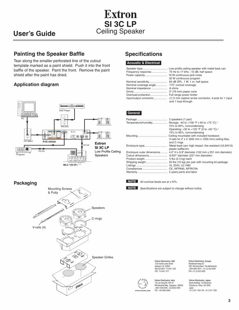
Application diagram
ExtronSI 3C LPLow Profile CeilingSpeakers
SI 3C LPCeiling SpeakerUser’s Guide
Packaging
SpecificationsAcoustic & Electrical
General
Speaker type................................. Low profile ceiling speaker with metal back can Frequency response..................... 75 Hz to 17 kHz, -10 dB, half spacePower capacity.............................. 16 W continuous pink noise 32 W continuous programNominal sensitivity........................ 83 dB SPL, 1 W, 1 m, half spaceNominal coverage angle............... 170° conical coverageNominal impedance ..................... 8 ohmsDriver............................................ 3” (76 mm) paper coneOverload protection....................... Full range power limiterInput/output connector.................. (1) 5 mm captive screw connector, 4-pole for 1 input and 1 loop-through
Package ....................................... 2 speakers (1 pair)Temperature/humidity.................... Storage: -40 to +158 °F (-40 to +70 °C) / 10% to 90%, noncondensing Operating: +32 to +122 °F (0 to +50 °C) / 10% to 90%, noncondensingMounting....................................... Ceiling mountable with included hardware: V-rails for 2’ x 4’ (600 mm x 1200 mm) ceiling tiles, and C-ringsEnclosure type.............................. Metal back can; high impact, fire-resistant (UL94V-0) plastic baffle/rimEnclosure outer dimensions.......... 4.0” H x 9.9” diameter (102 mm x 251 mm diameter)Cutout dimensions........................ 8.937” diameter (227 mm diameter)Product weight.............................. 5 lbs (2.3 kg) eachShipping weight............................. 20 lbs (10 kg) per pair with mounting kit packageListings ......................................... UL 2043, UL1480Compliances ................................ CE, NFPA90, NFPA70AWarranty ....................................... 5 years parts and labor
All nominal levels are at ±10%.
Specifications are subject to change without notice.
V-rails (4)
Mounting Screws& Putty
C-rings
Speakers
Speaker GrillesExtron Electronics, USA1230 South Lewis StreetAnaheim, CA 92805800.633.9876 714.491.1500 FAX 714.491.1517
Extron Electronics, EuropeBeeldschermweg 6C3821 AH Amersfoort, The Netherlands+800.3987.6673 +31.33.453.4040FAX +31.33.453.4050
Extron Electronics, Asia135 Joo Seng Rd. #04-01PM Industrial Bldg., Singapore 368363+800.7339.8766 +65.6383.4400 FAX +65.6383.4664
Extron Electronics, JapanKyodo Building, 16 IchibanchoChiyoda-ku, Tokyo 102-0082Japan+81.3.3511.7655 FAX +81.3.3511.7656www.extron.com
PVS 204SA
DVD Player
PVT RGB D
PVT CV D
AUDIO IN
VIDEO IN
MLC 104 IP+
RS-232
RS-232
Projector
+V G
SCP
+12V
OUT
PWR
SNS
GR
OU
ND
GR
OU
ND
GR
OU
ND
GROU
ND
GROU
NDTx Rx
HOST/CONFIG
LAN PRESS TAB WITH
TWEEKER TO REMOVE
A BA B E
SCPCOMM
MLSRS-232
PWR12V
PROJECTORRS-232/IR
Tx/IR R
x TxRx
+12V
IN
PC
COMPUTER IN
AUDIO IN
3