Shure Audio Systems Guide for Video Production
38
Video Production Audio Systems Guide Audio Systems Guide for A Shure Educational Publication By Christopher Lyons
Transcript of Shure Audio Systems Guide for Video Production

VideoProduction
Audio
Sys
tem
sG
uid
eAudio
Systems
Guide
for
A Shure Educational Publication
By Christopher Lyons

Preface . . . . . . . . . . . . . . . . . . . . . . . . . . . . . . . . . . . . . . . . 4
The Audio Chain . . . . . . . . . . . . . . . . . . . . . . . . . . . . . . . . . 5
Microphones . . . . . . . . . . . . . . . . . . . . . . . . . . . . . . . . . . . 5
Cables and Connectors . . . . . . . . . . . . . . . . . . . . . . . . . . 19
Mixers . . . . . . . . . . . . . . . . . . . . . . . . . . . . . . . . . . . . . . . . 21
Connecting to Camcorders . . . . . . . . . . . . . . . . . . . . . . . . 25
How to Handle Some Common Miking Situations . . . . . . 28
Troubleshooting . . . . . . . . . . . . . . . . . . . . . . . . . . . . . . . . 31
A Few Final Words . . . . . . . . . . . . . . . . . . . . . . . . . . . . . . 34
More Resources . . . . . . . . . . . . . . . . . . . . . . . . . . . . . . . . 35
Product Selection Charts . . . . . . . . . . . . . . . . . . . . . . . . . 36
About the Author . . . . . . . . . . . . . . . . . . . . . . . . . . . . . . . 38
Video
GuideProduction

4
PREFACE
Because the video production field is enjoying such rapid
growth, keeping up with its technological advancements
is a real challenge. The equipment used in video production is
becoming more sophisticated, practical, and accessible every
day, and more and more people are getting involved with video
projects of all kinds.
Shure has been deeply involved with the audio side of
video production for many years. If there’s one thing we’ve
learned over this time, it’s that audio quality is a key element
that can “make or break” any video project. No matter how
creative and well-executed the visual aspects of a production
may be, these qualities can be completely negated by
lackluster audio. To a greater degree than most people
realize, video projects stand or fall on the basis of their audio.
This booklet is intended to help anyone involved with
video projects improve the audio quality of their productions.
It is not intended as a comprehensive study of the subject of
audio. Its real goal is to provide helpful tips, practical advice,
and a general knowledge of audio tools – all with the express
purpose of making video productions as clear, understand-
able, and impressive as possible.
Technological advances have helped us make great
strides over the years in communicating with one
another. As a leader in audio technology, Shure has played a
major role in this process. No matter what your involvement
with video production may be, we’re confident that Shure
products will help you achieve the highest possible level of
audio excellence in your work. And we hope this booklet will
help you use our products with the greatest effectiveness.

5
THE AUDIO CHAIN
Almost everyone has used a simple cassette tape recorder at one time or another. In that instance, the process of recording sound is very simple:
press the Record button, talk into the microphone, and press the Stop buttonwhen finished. In the world of audio-for-video, however, there may be manypieces of equipment between the microphone and the videotape recorder. Thisseries of devices is collectively known as the audio chain. Common links in theaudio chain include a microphone (which transforms sound into an electricalsignal), a mixer (which adjusts the strength of the signal in relation to othersignals coming through the same system), and an equalizer, compressor, orother signal processor (all of which merely alter the signal and are optional).
When it comes out of the mixer (or whatever extra signal processingdevices are required), the signal is ready to be fed into the audio input jack of avideo tape recorder or to an amplifier for playback through loudspeakers.
MICROPHONES:
DIFFERENT TYPES AND WHEN TO USE THEM
The first step in getting the sound of someone’s voice on to your videotape is themicrophone. Microphones serve a very basic purpose: to change acoustic
energy to electrical energy. They convert sound waves into an electrical signalwhich can be modified, amplified, or recorded. Since the microphone’s function isso basic, you might well ask why there are so many different kinds of microphones.It’s simply because some types of microphones are better suited to certain usesthan others, just as pickup trucks are better than small sports cars for carrying large,heavy loads. If you are familiar with the different types of microphones, and howand when to use them, your productions will start sounding less like a home videoand more like the nightly news.
Audio chain

6
If you were asked to describe the kind of car you drive, you might answer interms of make, body style, or color. Similarly, microphones are commonlydescribed by four criteria: physical design, directionality, transducer type, andelectrical impedance. Each of these characteristics carries its own specialsignificance to the microphone’s overall suitability for various purposes.
PHYSICAL DESIGN
In choosing a microphone for a specific application, the first thing thatmust be considered is how it will be used. Will it be held by the persontalking? Will it be clipped to the user’s clothing? Will it be located a few feetaway from the subject, so that it remains out of the frame?
Handheld — The most common kind of microphone is the handheld type. Thisstyle is the most flexible, because it can be held by the user, mounted on a floor ordesk stand, or attached to a flexible “gooseneck” on a lectern. A good qualityhandheld mic should have an internal shock mount which will minimize handlingnoise (thumping sounds transmitted through the handle and picked up by themicrophone cartridge), and it should be ruggedly constructed to withstand physicalabuse. If you can have only one microphone in your kit of audio gear, it should bea handheld mic. Models at the upper end of the price scale will usually offer clearer,wider-range sound, better shock mounting, and more durable construction.
Tips on Using Handheld Mics: Whether held in the hand or mounted on astand, the microphone should be positioned about 6”-12” from the talker’s mouth,pointing up at about a 45-degree angle. With some types of microphones, holdingthe microphone very close (3”-6”) will cause additional emphasis of the lowerfrequencies (known as proximity effect), resulting in a “warmer”, bass-heavy sound.
Examples of different microphone designs
SM58 SM89 U2/87
MX393
MX202
WH10
WL183

7
Lavalier — Another popular mic for video use is the lavalier type.Historically, the word “lavalier” refers to microphones which are hung on acord around the wearer’s neck, but the term has grown to include almost anysmall microphone that attaches to the user’s clothing.
Lavalier microphones leave the talker’s hands free to gesture, hold notes,or demonstrate a product. In addition, they are usually very small and
therefore tend to disappear on camera. Also, using a lavalier will keep thedistance from the microphone to the talker’s mouth fairly constant, reducingthe need for frequent mixer adjustment once the levels have been set.
A disadvantage of lavalier mics is the fact that they tend to be single-purpose microphones - they rarely sound good if handheld or used awayfrom the body. While the lavalier mic’s small size makes it easy to concealbehind lamps or other objects, an equalizer is usually necessary to make themic sound natural when it is not attached to the person talking.
Tips on Using Lavalier Mics: For best results, lavalier mics should beplaced on the outside of clothing, about six to eight inches below the chin.They are generally clipped to a pocket, lapel, or necktie. If none of theseoptions are available, the mic can also be clipped to the collar of a shirt orblouse. Sound quality in this position tends to be somewhat muffled,however, because some high frequencies (which contain consonants) donot fully wrap around to the area under the chin.
Illustration: Ideally, a handheld microphone should be positioned six to twelve inches from the user’s mouth, at an angle of 45 degrees or less.
This usually avoids air currents that result in “popping” sounds when the consonants “P” or “T” are pronounced.

8
Concealing a lavalier microphone — In some productions, it is neces-sary to conceal the microphone. It is important to prevent both the micro-phone and the first few inches of cable from rubbing against either the bodyor clothing, which will cause noise. Here are some options:
• Under the shirt collar. The mic is lightly taped to the inside of a dressshirt collar, near the opening in front. The cable can be routed aroundto the back of the neck, over the collar and under the shirt.
• On eyeglasses, on the inside of the temple. The cable is routed overthe ear and down the back.
• On the forehead or cheek, secured with medical tape or gum. A disadvantage of this method is that the microphone is directlyexposed to perspiration and makeup.
• On the chest, secured with double-sided tape to both the skin and theinside of the shirt. Try to avoid placing the mic behind any materialhaving more than one layer. This reduces pickup of high frequencies,which results in a flat, “muddy” sound.
Double-miking — In some cases, even a remote chance that themicrophone might fail during a live event constitutes an intolerable risk. Forthis reason, a news anchor or key presenter may wear two lavaliermicrophones for redundancy.Only one mic is used at a time;if the primary mic fails, thebackup mic channel can beturned up immediately.
A lavalier microphone should be positioned six to eightinches below the wearer’s chin (Shure WL93 shown).

9
Double-miking with lavalier microphones is usually achieved with aspecial tie clip or bar that holds two microphones. (Note: When wirelessmicrophones are used, each lavalier mic must be connected to its own body-pack transmitter. These two transmitters must be on different operatingfrequencies, and their signals must be picked up by two different receivers,as discussed later.)
Surface Mount — These microphones are designed to work on a flatsurface. They are usually physically contoured to look less intrusive on aconference table or desktop. The microphone element is located very closeto (but not touching) the surface, so that sound waves reflected from thesurface arrive at the mic element at the same time as the direct sound. Thiseffectively doubles the sensitivity of the microphone compared to a free-standing handheld type at the same distance. (This sensitivity boostassumes that the surface is sufficiently large to reflect even low-frequencysound waves.)
Tips on Using Surface Mount Mics: Surface mount microphones workbest when positioned on a smooth, flat surface, such as a table or desk. Iftable vibrations are a problem, try putting a very thin piece of soft foamrubber underneath the mic. (A computer mouse pad with a hard top surfaceoften works well.) In some situations, surface mount mics can even workwell when mounted on a wall. Keep in mind that the sound quality of thistype of microphone is affected by the size of the surface on which it isplaced. For best results, use a surface at least 3 feet square; using a smallersurface will tend to reduce pickup of low frequencies. The effect on speechfrequencies is usually mild, and may actually improve intelligibility of very lowvoices by reducing boominess.
Shotgun — The shotgun microphone is so named because the long,slotted tube in front of the microphone cartridge makes it resemble ashotgun. This “interference tube” helps reject sounds coming from morethan about 30 degrees off to the sides, while still picking up sounds from thefront. This extremely directional pickup pattern (called a line/gradientpattern) makes shotgun mics popular for TV news and movie sets.
Shotgun microphones are not telephoto lenses for sound. They do notallow you to zoom in on a conversation from 100 feet away. Here’s a muchmore accurate analogy: imagine looking through a long tube at a personstanding 20 feet away. The person’s image does not appear to be any largeror closer, but is somewhat easier to see, because the eye is not distractedby things happening off to either side. This is exactly what shotgun mics dobest - screen out sounds coming from the sides. In practice, a shotgunmicrophone can typically be placed at four to five times the acceptabledistance for a standard omnidirectional microphone. Keep in mind that theshotgun mic will also pick up sounds coming from behind the subject.

10
Tips on Using Shotgun Mics: Shotgun mics can be positioned eitherslightly above, below, or to the side of the sound source, so that the micdoes not appear in the camera frame. Try to avoid aiming the mic at a hardsurface, such as a tile floor, brick wall, or hard ceiling. These surfaces reflectsound waves, and may reflect background noise into the microphone orcause the sound to be slightly hollow. A heavy blanket can be placed on areflective surface to provide some temporary sound absorption. Shotgunmics are more sensitive to wind noise than standard microphones, so try toavoid moving the mic rapidly and use a foam windscreen if possible. Larger“zeppelin” or “blimp” type windscreens are usually necessary outdoors.Also, it’s a good idea to use a rubber-isolated shock mount to controlhandling noise that may be transmitted through a stand or boom.
DIRECTIONALITY
Directionality is one of the most frequently misunderstood characteristicsof a microphone. Simply put, directionality describes how a microphoneresponds to sounds arriving from different directions or angles. Somemicrophones pick up sounds equally well from all angles, while others favorsounds from a particular direction. Understanding the significance of amicrophone’s directionality is vital to getting the most from its capabilities inany given miking situation.
The most common way of illustrating a microphone’s directionality is witha polar pattern. This is a circular graph which illustrates the relative soundpickup from different directions. Although many different polar patterns arepossible, the most common ones fall into two general categories:omnidirectional and unidirectional.
Omnidirectional — An omnidirectional microphone picks up soundequally from all directions (the prefix “omni” means “all”). An omni mic willpick up sound from above, below, in front of, behind, and to the side of themic in a 360 degree sphere. The polar pattern for an omni, then, is roughly
Polar pattern diagrams
CARDIOID (UNIDIRECTIONAL) MICROPHONE OMNIDIRECTIONAL MICROPHONE

11
circular. This can be advantageous, since one omnidirectional microphonecan be used to pick up voices from several directions, as long as eachperson talking is approximately the same loudness and the same distancefrom the microphone. The handheld microphones used by news reportersare usually omnidirectional, allowing the reporter and interviewee to bepicked up by one microphone held between them. It is important to notethat omnidirectional microphones do not suffer from the bass boostproximity effect mentioned earlier.
There are some drawbacks to consider when using omnidirectional mics,however. First, since they pick up sounds equally well from all directions,they may pick up undesired background noises (doors slamming, traffic,etc.) as well as the desired source. Second, they tend to pick up greateramounts of room reverberation when used in rooms that have hard-surfacedwalls and floors. This can sometimes result in a diffuse, hollow, “inside abarrel” sound. This effect may be minimized by moving the microphonecloser to the source and turning down the input level control at the mixer tocompensate. A third drawback to omnidirectional mics is that, when fedthrough a loudspeaker system for sound reinforcement, they tend toproduce feedback easily. (We’ll discuss feedback and room reverberation inmore detail in the Troubleshooting section.)
Unidirectional — A unidirectional microphone rejects sound comingfrom behind the mic while still picking up sound from the front. For thisreason, unidirectional microphones pick up less room reverberation and areless susceptible to feedback when used with loudspeaker systems. Thereare different kinds of mics that fall into this category, each one having aslightly different polar pattern and its own set of advantages anddisadvantages.
By far the most common type of unidirectional microphone is the cardioid,so named because its polar pattern resembles a heart-shaped figure. Mostcardioid mics will pick up less than half as much sound from the sides asfrom the front, and less than one tenth as much sound from the rear as fromthe front. So, the cardioid mic tends to pick up more of the desired soundand less of the undesired sound.
Other unidirectional types such as the supercardioid and hypercardioidhave progressively greater rejection of sounds from the sides, but pick upmore sound from the rear. Using these more directional patterns requiresthat the talker be more careful about staying directly “on mike” and notstraying off to the sides, where the mic’s sensitivity drops off rapidly.
Most types of microphones are available in both omnidirectional andunidirectional versions. Lavalier microphones are usually omnidirectional,although unidirectional models are becoming popular. The shotgunmicrophone is by definition extremely directional.

12
TRANSDUCER TYPE
As mentioned earlier, microphones serve just one purpose: to convertsound waves into electrical energy. The part of the mic that actually does theconversion is called the transducer or cartridge. But different types oftransducers perform the conversion in different ways, and each type oftransducer has certain characteristics that make it more or less suitable forvarious applications. For the most part, two types of transducers are usedin microphones for broadcast and audio-visual productions: the dynamicand the condenser.
Dynamic microphones (also called moving coil microphones) use asimple magnet and coil of wire to convert sound waves into an electricalsignal. Here’s how it works: a thin diaphragm with a coil of fine wireattached vibrates in response to sound waves. This causes the coil of wireto move back and forth around a magnet, creating a small amount ofelectricity, which flows through the microphone cable.
Good quality dynamic mics offer very good sound quality, are veryrugged, and will usually tolerate rough handling or exposure to extremetemperatures and humidity. For these reasons, dynamic microphones havetraditionally been the most popular for most professional applications.
Condenser microphones (also called capacitor or electret condensermicrophones) use an ultra-thin piece of plastic or metal stretched tight justabove a piece of flat metal or metal-coated ceramic, called a backplate.When a fixed electrical charge is placed on the diaphragm/backplateassembly, its electrical output varies depending on the movements of thediaphragm, which vibrates in response to sound waves. This output signalis extremely weak and subject to outside electrical interference, however, soit must be modified and/or amplified by a circuit called a preamplifier. Thepreamplifier can either be located in the handle of the microphone or in asmall outboard electronic pack.
Cutaway view of dynamic (left) and condenser microphone cartridges

13
Condenser microphones offer several benefits. The most important ofthese is that they can be made very small, which is why all miniature lavaliermicrophones are condenser types. Condensers tend to be very sensitive tothe extreme low and high frequencies, and usually have a very crisp, cleansound. Their built-in preamplifiers allow condenser mics to provide higheroutput than dynamic mics, meaning that for a given sound level, a strongerelectrical signal comes out. This may be helpful when you are trying to pickup someone who speaks very softly, or who is further away.
You’ll encounter one inconvenience in using condenser mics, however, inthat the preamplifier requires electricity to work. On some microphones, thiscan come from a battery carried inside the handle of the mic or in thepreamplifier pack. Power can also be supplied from the mixer or otherequipment that the mic is plugged into, if it is so equipped. This is calledphantom power, and will be discussed later.
ELECTRICAL IMPEDANCE
Impedance is an electrical characteristic of audio equipment, just likevoltage or current. It is expressed in ohms, the symbol for which is Ω.Microphones are typically classified as being low-impedance (also calledlow-Z) or high-impedance (also called high-Z). For professionalapplications, only low-impedance microphones should be used. High-impedance microphones usually begin to sound muffled due to a loss ofhigh frequencies when used with a cable longer than 20 feet. One of theadvantages of low-impedance microphones is that they allow you to usevery long runs of cable (over 1000 feet) with negligible loss of sound quality.
It’s usually not difficult to tell if the microphone you’re using is high-imped-ance or low-impedance; just look at the nameplate or specification sheet.The words “high-Z”, “high impedance”, or a rating of 10,000 ohms or higherall indicate a high-impedance microphone. “Low-Z”, “low impedance”, or arating of 600 ohms or less indicate that the mic is low-impedance. High-impedance microphones can only be connected to high-impedance audioinputs. Use of a matching transformer (which will be discussed later) canfacilitate connection of high-impedance mics to low-impedance inputs, orlow-impedance mics to high-impedance equipment.
It is important to note that the impedance of a microphone should notmatch the impedance of the input to which it is connected. In fact, matchingthe impedance causes a significant loss of signal level. The tradition ofmatching impedances originates in the early days of electronics, whenamplifiers were based on vacuum tubes. With modern transistorizedelectronics, low impedance devices (such as microphones) should alwaysbe connected to an input whose impedance is higher — preferably 5 to 10times higher. For this reason, the inputs on professional mixers typicallyhave an impedance of 1000 ohms or higher.

14
PHANTOM POWER
A little earlier, we talked about the fact that condenser microphones require electrical power to operate (usually between 11 and 48 volts DC).Phantom powering is a method of supplying that power through themicrophone cable from a remote supply. This supply can be a stand-aloneunit or may be incorporated in the audio mixer, or, in some cases, the videorecorder. It is called "phantom" power because it comes from somewhereoutside the microphone and is not supplied by a battery.
While it’s a popular myth, plugging a dynamic microphone (which doesn’tneed any power to work) into a mixer that is supplying phantom power willnot damage the microphone. As long as you are using a balancedmicrophone, phantom power cannot possibly cause it to burn out, or harm itin any way. If you connect an unbalanced microphone to an input that issupplying phantom power, you may hear a steady hum or buzz. To get rid ofit, just turn off the phantom power supply. (We’ll discuss the concept of“balanced” and “unbalanced” in the Cables and Connectors section.)
Phantom power is occasionally referred to as simplex power; the two areone and the same electrically. You may also encounter some Europeanmicrophones which require a different type of power called A-B power or T power. These are electrically incompatible with phantom power.Microphones which operate on phantom power will not operate on A-Bpower, and vice-versa. Some mixers can provide phantom power and A-Bpower to different mic inputs simultaneously.
WHAT ABOUT WIRELESS?
Wireless microphones (occasionally referred to as “RF mics” or “radio mics”)have become increasingly popular in the last few years, especially in situationswhere the presence of a conventional mic cable puts constraints on the user’sactions. In essence, a wireless microphone is a miniature radio station. Amicrophone cartridge (which may be a dynamic or condenser type) convertsincoming sound waves to an electrical signal. The signal is sent out by a low-power transmitter, and then picked up by a receiver located nearby, whichconverts the radio-frequency signal back into audio. The transmitter can becontained in the handle of the microphone or in a small pack designed to be wornon the body. The combination of the microphone, transmitter, and receiver isknown as a wireless system. A cable then connects the audio output of thereceiver to the input of the audio mixer or videotape recorder.
Just like radio stations, wireless microphones operate on specific frequenciesin sections of the frequency band which are regulated by the FederalCommunications Commission (FCC). These frequencies are measured inmegahertz (abbreviated “MHz”), which describes the number of times that thesignal oscillates or vibrates in one second. Wireless microphone systems areavailable in different sections of the frequency band:

15
The low-band VHF (49-72 MHz) range is utilized by radio-controlled toys,cordless telephones, baby room monitors, and other consumer products.Wireless microphone systems on these frequencies — particularly 49 MHz— are likely to pick up interference from some of those items. While low-band VHF systems are typically very inexpensive, their performance isgenerally acceptable only for home video recording use.
The high-band VHF (169-216 MHz) range is the most widely used forprofessional applications, and quality systems are available at a variety ofprices. This region is the same one in which VHF television stations(channels 7-13) broadcast, so it is important to be aware of which stationsare in the geographic area where the wireless system is to be used. InChicago, for instance, there are TV stations on channels 7, 9, and 11, sowireless systems operating in channels 8, 10, 12, or 13 may be used.Manufacturers of wireless systems can help you select the optimalfrequencies for use in your area, considering other units already in use atyour location and the number of systems to be used.
If you intend to use your VHF wireless microphone system in various partsof the country, you might choose one of the so-called “traveling”frequencies. These are frequencies in the 169-172 MHz range which are justbelow channel 7, and therefore not subject to interference from TV stations.Traveling frequencies are by far the most crowded, however, and in someareas they are used by navigation buoys or hydroelectric equipment tobroadcast control signals which may interfere with your wireless mic. Keepthis in mind when using wireless microphones near coastal areas or dams.
The UHF frequency range has become more popular as congestion in theVHF band has increased. Since the UHF band is generally less crowdedthan VHF, there is less chance of encountering interference from anotheruser on the same frequency. There is no inherent difference in sound quality
Audio chain incorporating a wireless microphone system
WirelessMicrophoneTransmitter Camcorder with Receiver

16
between UHF and VHF wireless microphones. Due to their more complexdesign and circuitry, however, UHF systems are typically more expensivethan comparable VHF systems. It should be noted that UHF and high-bandVHF frequencies are reserved by the FCC for use in broadcast and film/videoproduction, but it is the responsibility of the purchaser to observe FCC rulesregarding their use. Regulations regarding authorized use of thesefrequencies have not been strongly enforced in the past, however, with theresult that it is not unusual to find professional frequencies being used byunauthorized users.
Once you’ve narrowed down the list of possible frequencies to use, youneed to decide which of the two types of receivers you need: single antennaor diversity. The first type utilizes a single antenna mounted on the back ofthe receiver. The RF signal from the transmitter’s antenna radiates in alldirections, and gets reflected off large surfaces like walls and ceilings. Thereflected signal can add to or subtract from the direct signal, sometimesresulting in a net signal strength of zero at the receiving antenna’s position.This condition, known as multipath interference, may come and go rapidlyas the person carrying the transmitter moves around the room, causing theRF signal to be interrupted for a fraction of a second. This is called adropout. Depending on the duration and severity of the dropout, you mayhear a quick “pfft” sound, a brief buzz or crackle, or a complete loss of audio.
Diversity receivers do a better job of resisting signal interruptions. They utilizetwo antennas — mounted a short distance from each other — and a “smart” circuitthat selects the better of the two signals at any given moment. Diversity receiversprovide a noticeable improvement in audio quality, since it is unlikely that the signalto both antennas will be interrupted at the same instant.
Portable battery-powered wireless receivers are available for use in situationswhere both the transmitter and the receiver must move around. These units arevery small — usually about the size of a cigarette pack — and can be worn on the
Non-diversity and diversity explanation

17
body or mounted directly to a small mixer or camcorder. A short cable connectsthe audio output of the portable receiver to the audio input of the mixer orcamcorder. Better models offer a separate headphone output, so that the cameraoperator can monitor the audio through headphones or an ear piece. A wirelessmicrophone system which includes a portable receiver is a very handy thing tohave on a video shoot. For instance, one or more receivers can be attached tothe top of a portable audio mixer, which then feeds audio to the camcorderthrough a short cable. This way, the talent, the camera operator, and the soundengineer can all move about freely when the script requires such a shot.
Another application for a portable wireless receiver is to feed audio from themixer to a camcorder located across the room. In a large meeting room, forexample, the audio mixer is often located at one side of the stage, while thecamcorder is at the back of the room. In such a scenario, an output from themixer can be connected to the input of the wireless transmitter, and the portablereceiver attached to the camcorder. This eliminates the need to rely on thecamcorder’s internal microphone, which is usually too distant from the talkersto provide satisfactory sound quality.
A new spin on the portable receiver concept is the wireless in-ear monitorsystem. This is a wireless system specifically designed to feed audio to thetalent’s ears, rather than to a mixer or camcorder. The desired signal isconnected to a stationary transmitter, which broadcasts the signal to anynumber of body-pack receivers worn by talent or crew members. The receiverfeeds small earpieces that are nearly invisible on camera. The receiver must beequipped with a headphone volume control so that the listener may adjust thevolume to a level that is comfortable and safe. Better systems offer the optionof transmitting either stereo audio or two simultaneous mono channels, whichthe listener can blend and adjust to their preference.
Example of a wireless diversity system (Shure UC Wireless shown).

18
Wireless in-ear or “personal” monitors can be used in a variety of ways inthe broadcast or video production environment. Reporters in the field canhear questions and answers from the broadcast studio; the narrator of avideo program can listen to a prerecorded script while simultaneously recit-ing it (sometimes called an “ear prompter”); an actor can hear stereo musicplayback while singing along; a presenter can hear questions picked up byaudience microphones. In many applications, the director can cut in to giveinstructions; the monitor signal is then called Interruptible Foldback, or IFB.
Tips on Using Wireless Systems: When using wireless microphonesystems, try to keep the distance from transmitter to receiver as short aspossible. Always do a “walkaround” before the event begins; that is, listento the system while walking around the anticipated performance area. Ifdropouts occur, try moving the receiver a few feet and repeat thewalkaround. If possible, the walkaround should be done at the same time ofday as the event, to expose nearby users of the frequencies on which youintend to operate. When using belt-pack type transmitters, be sure that theantenna cable is hanging straight. If it is coiled up in the wearer’s pocket,transmission distance will be significantly reduced. With handheldtransmitters that have an external antenna, discourage users from holdingtheir hand over the antenna, which will reduce transmission range andincrease the likelihood of dropouts.
Example of a Personal Stereo Monitoring (PSM) System (Shure P6HWE1 wired system shown).

19
CABLES AND CONNECTORS
Cables and connectors are probably the most overlooked link in theaudio chain, and yet poor quality cables and/or faulty connectors are
frequently the cause of major audio problems.
There are basically two kinds of connections used between audiodevices: balanced and unbalanced. A balanced connection requires acable with two wires (one for the “hot” signal and one for the “return”)enclosed by a shield of metal foil, braid, or mesh. The shield intercepts therandom electrical signals that bombard the cable from various sources anddrains them to ground. Together, the wires and the shield keep the audiosignal free of interference. For applications in which cables will be frequentlydisconnected and coiled up for storage, choose those which use braid ormesh shielding; these are more resistant than metal foil to cracks or tearsdue to flexing, which can cause electrical shorts.
An unbalanced connection utilizes a cable with a single wire surroundedby a shield, but in this case the shield has to do double-duty. It carries the“return” portion of the audio signal as well as protecting the wire inside fromelectrical interference. This method is not nearly as effective as the balancedtype, so unbalanced audio cables are easily affected by florescent lightfixtures, some types of dimmer switches, and other audio or electrical cablesthat may be nearby.
Balanced audio connections are generally used with low-impedanceequipment, while unbalanced connections are used with high-impedanceequipment. You may encounter exceptions, however. As a rule, balancedconnections will offer much cleaner, noise-free performance.
You may be wondering, “How will I know if a connection is balanced orunbalanced without cutting the cable open to look?” Fortunately, you canmake a pretty accurate guess by looking at the connectors on each end ofthe cable. As you’ve probably found out, there are several different kinds ofconnectors found on audio equipment, and some are better than others.
Today, the most popular connector for professional microphones andaudio equipment is the XLR connector. Male XLR connectors have threepins, and are used for signal output; female XLR connectors have threesockets, and are used for signal input. The XLR connector is very rugged,rarely bends or breaks off while connected, and most versions lock togethersecurely so that accidental unplugging is unlikely. A cable that has an XLRconnector at both ends almost certainly indicates a balanced connection.XLR connectors are found on both low- and high-impedance microphones.

20
Another popular audio connector is the male 1/4 inch phone plug, whichmates with the female 1/4 inch phone jack. The name originates from use ofthis connector on early telephone switchboards. These can be found oncables used with almost any type of audio equipment: headphones,loudspeakers, amplifiers, signal processing gear, and microphones. Two-conductor types (sometimes called “TS” or “tip-sleeve”, which refers to thearea of the connector used for each wire) have two distinct segments andare used for unbalanced mono connections. Three-conductor types(sometimes called “TRS” or “tip-ring-sleeve”) can be configured to carry abalanced mono signal or an unbalanced stereo signal. Microphones andmicrophone inputs on mixers using 1/4 inch phone connectors are almostalways of the unbalanced high-impedance type.
Another type of audio connector is the miniplug. Miniplugs come in twosizes. The 3.5 millimeter version is the same size as those used onWalkman-type headphones; the 2.5 millimeter size is frequently used for theearphones supplied with transistor radios. The miniplug resembles aminiaturized version of the 1/4 inch type, and is notorious for bending orbreaking if bumped while plugged in. Due to their small size, however,miniplug connectors are frequently used on consumer and even semi-professional video equipment. They almost always indicate an unbalancedaudio connection, but whether the input is low-Z, high-Z or somewhere inbetween is usually anybody’s guess. Most microphones that comeequipped with miniplugs are low-cost units designed for inexpensive taperecorders. If your equipment only has a miniplug or 1/4” microphone input,you can still use a good quality professional mic. You just need to obtain acable with the appropriate connectors, or in some cases, an impedancetransformer (more about equipment interconnection later).
The fourth type of connector you’ll run into is the male RCA plug or phonoplug, which mates with the female phono jack. The name “phono” comesfrom the fact that these are the standard for connecting phonograph
Connectors commonly used for audio (left to right): XLR (male), XLR (female),1/4-inch phone plug, RCA or phono plug, 3.5 mm mini plug.
21
turntables (as well as tape decks, CD players, and so on) to home stereoequipment. Phono plugs are really not designed to be inserted andremoved over and over again, as doing so will eventually result in a brokenor intermittent electrical connection. At that point, the usual procedure is tothrow the cable away and buy a new one; the problem is that you neverknow when it’s going to happen.
If you are upgrading your audio equipment and are thinking about buyingbetter microphones, it goes without saying that you should invest in someheavy-duty microphone cables with XLR connectors. If your equipment uses1/4", miniplug, or RCA connectors, buy professional quality cables with metalconnectors that can be disassembled for service rather than molded-onplastic connectors. If you do have a problem with a connection, you canrepair it rather than replace the entire cable. It is a good idea to carry onespare cable of each type that you use, so that you can change a suspectcable quickly when a problem arises.
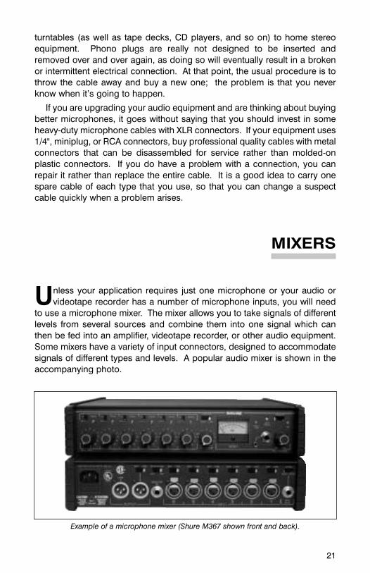
MIXERS
Unless your application requires just one microphone or your audio orvideotape recorder has a number of microphone inputs, you will need
to use a microphone mixer. The mixer allows you to take signals of differentlevels from several sources and combine them into one signal which canthen be fed into an amplifier, videotape recorder, or other audio equipment.Some mixers have a variety of input connectors, designed to accommodatesignals of different types and levels. A popular audio mixer is shown in theaccompanying photo.
Example of a microphone mixer (Shure M367 shown front and back).

22
MIC AND LINE — WHAT DO THEY MEAN?
Some mixers have switches on the rear panel for setting each input oroutput jack for mic level or line level. These refer to the signal level orintensity that the input is designed to accept.
A mic-level or microphone-level signal is the amount of voltage thatcomes out of a microphone when someone speaks into it - just a few ten-thousandths of a volt. (Of course, this voltage varies somewhat in responseto changes in speaking volume and source-to-mic distance.) A line-levelsignal is approximately one volt, or about 10,000 times as strong as a mic-level signal, so the two do not ordinarily use the same input. Connecting amicrophone to a line-level input will result in almost no sound at all, becausethe signal is so faint that the line input cannot hear it. Connecting a line-levelsource (such as a CD player) to a mic-level input will cause the sound to beloud and distorted because the line signal is much stronger than what themic input will accept. Inputs and outputs on better mixers are switchable foreither mic or line level operation.
You may also encounter jacks marked “aux” (or “tape”) and “phono”.Aux-level inputs and outputs are found on many kinds of equipment,including VCR’s, tape recorders, CD players, and some computer soundcards. Aux-level is somewhat close to line-level, but aux-level inputs andoutputs are nearly always unbalanced, using RCA or 1/4” connectors.Microphones cannot be connected directly to aux inputs. Jacks markedphono are for phonograph turntables only, and are not compatible withanything else.
MIXER FEATURES
On the front panel of the mixer (shown on page 21) are low-cut filter switchesfor each input. Such switches are often labeled “In” and “Out” rather than “On”and “Off”, a custom resulting from the fact that some additional circuitry is beingplaced “in” the signal path. Moving these switches to the “In” or “On” positionfilters out some of the low frequencies from the signals on those channels. Thisfeature comes in handy for reducing the rumbling noises which often come fromair conditioning, wind noise, etc. The limiter feature is extremely useful, and it willnot hurt to leave it on all the time. A limiter acts as a ceiling for the audio signal,and tries to keep it below the point at which distortion occurs. Some limiters canbe adjusted to activate at different levels, called the threshold. The switch marked“osc” controls the built-in tone oscillator, sometimes called a tone generator. Thistone, usually at a frequency of 1,000 Hertz, is used for adjusting severalconnected pieces of equipment (see section on setting levels for more details.)
On the rear panel of the mixer, (shown on page 21) on the right side, is a jackmarked “mix bus”. This jack allows you to connect two mixers together whenyour application requires more than the inputs available on one mixer. All inputsignals from both mixers would then be combined at each mixer’s output. Inother words, the outputs of each mixer would be duplicates of each other.

23
AUTOMATIC MIXERS
Problems often arise when multiple microphones are used for recording orsound reinforcement. As more microphones are added, pickup of reverberationand unwanted room noise increases, which decreases intelligibility. In situationswhere a sound reinforcement system is being used, additional microphones alsoincrease the likelihood of feedback or “howling”. These problems cause listenerfatigue, as it becomes necessary to concentrate harder to comprehend thetalker’s message. The solution is to activate microphones only when they arebeing addressed and to keep them turned down when they are not needed. Inaddition, when more than one microphone is addressed at a time, the overallsound system volume must be reduced slightly to prevent feedback.
Automatic or voice-activated mixers are designed to do both of these things,without the aid of a live operator. Automatic mixers have special circuitry addedwhich senses when sound is arriving at a microphone, and then turns on thatmicrophone. The best units are able to turn on or “gate” the microphone in justa few thousandths of a second - so fast that not even the first syllable is missed.Some automatic mixers use ordinary microphones, while other types requirespecial microphones. The latter type can actually sense the location of the soundsource and activate the microphone only when the sound comes from thedesired direction. This prevents background noises, such as doors opening,from fooling the mixer, no matter how loud they are.
SETTING AND ADJUSTING LEVELS
To achieve professional sounding results, it is important that the mixer youuse is equipped with a meter. Without one, it is nearly impossible to adjustsignal levels properly. The most popular type is called a VU meter (VUstands for “volume units”), and may be in the form of either a needle-typeindicator or a series of light-emitting diodes (LED’s).
During setup, first set the master gain control knob to about 3 or 4. Thenhave each speaker talk into his or her microphone in a normal voice. Don’tlet them lean close to the microphone and quietly say “hello” - have themstate their name and enough other miscellaneous information (hometown,etc.) to give you enough time to set an accurate level. Watch the metercarefully, and adjust the input channel knob (also called a “fader” or “pot”)so that the needle hovers below 0 VU, and only occasionally goes into the redzone. If the meter is ever “pegged” (with the needle hitting the far end of thescale), it means you’ve set that input level too high. Repeat this procedurefor each input channel. If you will be turning down mics that are not beingaddressed, write down the appropriate setting for each channel on a piece oftape and stick it on top of or in front of the mixer; this will make it easier toset the right level quickly when someone begins talking. As the event begins,watch your levels carefully; people often speak significantly louder when theyare live. For more dynamic talkers, you may have to turn their average leveldown quite low in order to accommodate the occasional loud outburst.

24
The mixer’s tone oscillator and meter can also be used to establish consistentlevels among several pieces of audio gear. For instance, during setup, the mixer’stone oscillator could be turned on, and the mixer’s Master Output level control
adjusted so that the mixer’s output isset at a known level (as indicated on thelevel meter). The input of the recorderconnected to the mixer would then beadjusted until its level meter indicatedthe same level as shown at the mixer.This means that acceptable readingson the mixer’s meter during tapingshould also indicate acceptable levelsat the recorder.
Different pieces of equipment mayhave dramatically different audioperformance. You may find that youhave to keep the mixer’s output levelvery low to avoid overloading the inputof a video recorder. If the recorder’saudio input is designed in such a waythat it overloads easily (without muchheadroom in other words), there is notmuch that you can do.
An important rule to rememberwhen adjusting levels is keep inputhigh, master low. In other words, it’sbetter to have the input levels set at 7or 8 and the master level set at 3 thanto have the input levels at 3 and themaster level at 8. Most of the internalnoise or hiss produced by a mixercomes from the master outputsection, so the higher your masterlevel control is set, the morenoticeable this noise will be.
Monitor your audio! It is notuncommon for speaking or backgroundnoise levels to change significantlyduring a video shoot or other event, andif you’re not listening, you won’t find outuntil it’s too late. Use a pair of lightweightheadphones or a small earpiece tomonitor - after all, how often do you tapean event without looking through yourcamera’s viewfinder!
Average VU meter reading if levelis set too high; may result in signal
overload distortion
Average reading if level is set too low; mayresult in inadequate signal.
Average reading if level is properly set.

25
CONNECTING TO CAMCORDERS
Connecting a microphone with an XLR connector to a mixer input with anXLR connector is simple. Things can get more complicated when you
must interconnect balanced and unbalanced devices, mono and stereodevices, or devices with different types of connectors. Connecting amicrophone to a consumer or semi-professional camcorder equipped with a3.5 mm miniplug microphone input is a good example.
Camcorders use a variety of microphone input connectors and wiringschemes. Unfortunately, there is no ‘standard’ to which camcordermanufacturers must adhere, and the specifications provided with thecamcorder often say little or nothing about the microphone input. Mostcamcorder microphone inputs fall into one of three groups, however; thetrick is knowing which group your camcorder is in. The key questions are:
• Is the camcorder mono or stereo? If it is stereo, we assume that you wish torecord the audio from your microphone onto both the left and right channels.
• If it is mono, does the microphone input jack supply DC voltage (sometimeslabeled “Mic Power” or “+3 vdc”) for the manufacturer’s own accessorymicrophone? This DC voltage is not the same as the phantom power usedfor professional condenser microphones. Microphones or wirelessreceivers that do not require this power must be connected in such a way
Examples of a portable stereo mixer (Shure FP33 shown above), headphone monitor(Shure FP22 shown bottom left) and mic-to-line amplifier (Shure FP11 shown).
FP11FP22
FP33

26
as to avoid contact with it. Professional condenser microphones requiringphantom power cannot be directly connected to a camcorder; a separatephantom power supply is required.
• If the camcorder is stereo, are there separate mono input jacks for the leftand right channels, or a single stereo input jack that feeds both channels?If there are separate mono jacks, do they supply DC power.
Is a Transformer Necessary?
If the length of cable between the microphone and the camcorder will be 20feet or less, all that is necessary is to use a cable with the appropriate connectorsand wiring. If the cable will be longer than 20 feet, however, a transformer will berequired at the end of the cable nearest the camcorder. The camcorder-side ofthe transformer is typically equipped with a very short cable and a 3.5mm monoor stereo connector. The transformer provides two benefits:
• The transformer maintains a balanced connection between itself andthe microphone, minimizing pickup of hum and electromagneticinterference and allowing for cable runs of up to 1,000 feet. (Longercable runs require a mixer or preamplifier to boost the microphonesignal up to Line level, about 1 volt.)
• The transformer can boost the signal level slightly, which may be usefulwhen connecting a low-output microphone (or one used at aconsiderable distance from the sound source) to a camcorder whosemicrophone input is not very sensitive. The amount of boost (called“gain”) that the transformer provides depends on the ratio between itsinput and output impedances, as well as the ratio between thetransformer’s output impedance and the camcorder’s input impedance.Typical transformers provide between 6 dB and 12 dB of gain.
Connecting a Mixer to a Camcorder
The output of a mixer can be connected to a camcorder’s mic input if themixer has a mic level output. If the mixer only has a line level output, its levelmust be attenuated (decreased) by approximately 50 dB to preventoverloading of the camcorder’s microphone input circuitry. A device calledan attenuator is used for this purpose. Some attenuators offer a choice ofsettings to provide varying amounts of attenuation. Some camcorders havea line level input in addition to the mic input.
If the cable run from the mixer to the camcorder is longer than 20 feet, atransformer is re-quired, as discussed previously. Note: The mixer musthave a mic level output, OR the transformer must be capable of handling aline level signal from the mixer without being overloaded (most cannot).

27
Dealing with Automatic Gain Control
Most consumer-grade camcorders and some industrial models have anAutomatic Gain Control (AGC), which adjusts the audio level up or down asnecessary. The AGC circuit is designed to compensate for the fact that the soundsource is often far from the microphone on the camera. An external microphone isusually placed much closer to the source, however, and therefore a much highersignal level is fed into the camera’s input. The Automatic Gain Control responds byrapidly reducing the audio level during the peaks of speech, and boosting the levelup very high during pauses. The sound of the AGC’s action is often described as“pumping”, “breathing”, or “whooshing”, and is usually undesirable.
It is impossible to defeat or bypass the AGC on most camcorders. The only other options are:
• Use the camcorder’s line-level input, if it has one. On most camcorders, the lineinput is not affected by the AGC. But since a microphone signal is not strongenough to drive the line input directly, the mic must be connected to a mixer ormicrophone preamplifier that has a line level output. Using a mixer also allowsfor more precise adjustment and metering of signal levels, in addition to its basicfunction of combining the signals from multiple microphones into one feed.
• Keep the external mic signal level very low. This causes the AGC to relaxand let the audio level rise to maximum. This tends to amplify the hiss of thecamera’s audio circuitry, but reduces the pumping action. Themicrophone’s output signal can be reduced by moving it farther away fromthe source, or by using a device called an attenuator or pad, whichdecreases the signal level by a fixed amount. Some attenuators offer achoice of settings, such as -15 dB, -20 dB, and -25 dB.
Connecting microphones to camcorders

28
HOW TO HANDLE SOME COMMON MIKING SITUATIONS
Following are some hints on choosing the right mics for some commonaudio/video applications. In most situations, there is no single “right way” to
do it, but some ways may be better than others. In some cases, you may decideto sacrifice some sound quality in order to gain some other, more importantbenefit, such as accommodating your subject’s refusal to wear a lavalier mic.There are some general ground rules that always apply, however:
1. Always place the microphone as close as is practical to the soundsource. Every time the source-to-mic distance increases by a factorof two, the sound pressure level (SPL) reaching the mic decreasesby a factor of four, making clear sound pickup progressively moredifficult. This is called the inverse-square rule, and it applieswhether the distance increases from 6 inches to 12 inches or from6 feet to 12 feet. This means that the talker-to-mic distance must becut in half to cause a significant improvement in sound quality.
2. Use the lowest number of microphones necessary for the situation.People sometimes have a tendency to “over-mike” a shot, usingthree or four microphones when one or two would be sufficient.Excess mics mean more background noise pickup, greater chanceof feedback or “tin can” sound (both of which we’ll discuss in theTroubleshooting section), and more levels for the operator to keeptrack of. If additional mics don’t make things sound better, then theywill probably make things sound worse.
Situation #1 — The Standup Shot: In this situation, a company officer orother speaker is either standing or sitting, speaking directly to the camera. Ifthis takes place in a studio or quiet office, the best mic to use would be alavalier, since the speaker’s hands would be free to gesture and we wouldeliminate the possibility of a handheld mic being positioned incorrectly or,worse yet, moved around. The unobtrusiveness of a lavalier mic also tendsto put the talker more at ease, resulting in a more natural look and sound.
If the shot takes place outdoors or in a noisy factory, you will need aunidirectional mic to cut down the background noise. You could: 1) use aunidirectional lavalier mic, 2) have the speaker hold a handheld uni-directional mic (or put one on a stand in front of him), or 3) use a shotgunmic on a boom, positioned so that it does not appear in the video frame.This method also permits the talker to move around without getting tangledin a microphone cable.

29
Situation #2 — The Product Demo Shot: This time our speaker isdemonstrating a product on a table. Before you decide what type ofmicrophone to use, stop and think for a moment. Does this product makeany sound at all when demonstrated? If so, how loud is it? Do you want thesound to be part of the demonstration? If the product makes little or no noise(like a personal computer, for instance), your best bet is probably to put alavalier mic on the speaker’s clothing in a spot where it will not be disturbedby his movements.
If the product is a food processor, though, your only chance is to use thelavalier or a shotgun to pick up the first part of the demo (before the productis turned on), and then record the rest of the demo without any narration —justthe sound of the unit working. Have the speaker do a voice-over without themachine on, which you can dub in later. Otherwise, you’ll have to use ashotgun mic positioned no more than a foot away from the speaker’s mouthand perpendicular to the food processor for minimal noise pickup.
If the product is very small and you have to pick up its sound (such as thatof a digital watch alarm beeping), you will need to use a second micpositioned close to it, or else a shotgun a few inches away from it.
Situation #3 — The Panel Discussion Shot: Here, your assignment is totape a panel discussion before a live audience. Let’s say that there are five peo-ple on the panel, and you also wish to pick up the questions and comments ofthe audience. You will be operating the camera yourself, so all the microphoneswill be on at all times to ensure that no comments are missed.
How many mics you use on the panel depends largely on how closely togetherthey are seated — you may be able to pair people up and use one microphone foreach pair. Keep in mind that microphone positioning has a significant effect onsound quality, however. The rule for this situation is widely known amongprofessional audio engineers, and you would do well to memorize it:
The 3-to-1 Rule — The distance between open microphones should be atleast three times the distance from each microphone to the nearest talker.
For example, if you place a microphone one foot in front of each talker,the mics should be at least three feet apart form each other. Placing the micscloser together will result in a hollow, “tin can” sound, caused by the samesound reaching more than one microphone at slightly different times. If it’sconvenient to have panel members positioned in pairs as mentioned above,you could separate each pair by a distance greater than three feet, allowingthe microphones to be further away from each pair of talkers.
The best solution would be to turn off microphones that are not beingaddressed, which would keep the number of open microphones to aminimum and make the distance between mics less critical. This could bedone either by a live operator or with a voice-activated mixer.

30
Picking up audience questions is a perennial problem for audio people,primarily because there is no really effective way to do it. For their commentsto be intelligible, you have two choices: bring the audience to a microphone,or bring a microphone to the audience. In other words, you could place amic on a stand somewhere in the room and ask people to move to thatlocation if they have a comment. Or, you could assign a person (or persons)the task of walking around the room with a wireless mic and going to eachperson who has a question. You’re probably wondering about pointing ashotgun mic at each person to pick up their questions, but this doesn’t workvery well. Shotgun mics are not very effective beyond 20 feet in a largecrowded room, which means you will only be able to understand thosepeople in the front row.
Situation #4 — The Conference Table Shot: Your main goal in thissituation is to videotape a meeting of eight people seated around arectangular conference table. You might think that the obvious solutionwould be to put a lavalier microphone on each person, but this arrangementwould pick up tremendous amounts of room noise if all eight mics were lefton at once. Having an operator bring each mic up and down as neededwould probably prove unsatisfactory, since the flow of conversation mightmove too fast for the operator to keep up.
Your best bet here is to use two omnidirectional surface mountmicrophones, located so that one mic is centered on each half of the table.Each person should be approximately the same distance from the nearestmicrophone. Otherwise, levels will be inconsistent and some speakers willnot be picked up as well as others. If an audio person is available, he or shecould also use a shotgun mic on a boom, although this method would makeit difficult to pick up more than one person at a time. As we mentionedpreviously, a voice-activated mixer would be an excellent alternative.

TROUBLESHOOTING
No matter how well you plan ahead, sooner or later you will probably runinto an audio-related problem. To help you out in those situations,
we’ve listed some of the more common problems encountered in doingaudio-for-video, along with some possible solutions.
1. Buzz, hum, crackle, and other noises — These are almost always causedby an electrical problem somewhere in the system. A low, steady buzz orintermittent crackle usually indicates a loose ground wire, probably in ornear a connector. A humming sound is usually picked up by unbalancedcables near light fixtures, dimmer switches, or power or loudspeakercables. You can try moving the mic cable around a bit, but the onlypermanent solution is to use balanced microphone cables. If yourmicrophone is the unbalanced, high-impedance type, you can saveyourself some headaches by using an in-line transformer which converts
31
Two methods for miking a conference table
Unidirectional
Omnidirectional

32
the signal to the balanced, low-Z configuration. You can then plug the micinto a balanced mic input or use another transformer to convert the signalback to high-Z to match the equipment’s input. It’s important that thetransformer is used as close to the microphone end of the cable aspossible, so that the majority of its length is balanced. Placing thetransformer at the mixer input will not make the mic cable more resistantto electrical noise.
2. Distortion — This “fuzziness” or general lack ofclarity results whenthe input of somepiece of equipmentin your audio chainis being overloaded(a condition calledclipping). Once thesignal is distorted,there is absolutelyno way to removethe distortion withanother devicefurther down theaudio chain. If thesignal level comingfrom the microphoneis too high for the mixer and sounds distorted, for example, you must turndown that channel’s input level control on the mixer. Adjusting the inputcontrol on the videotape recorder will not help. If the range of adjustmentis not wide enough, you can use an attenuator (also called a pad), whichreduces the level of the signal by a specified amount without altering itssound. The amount of attenuation is measured in decibels, or “dB” forshort. A 10 dB or 20 dB attenuator is frequently all that is required tomake a signal easier for the mixer to deal with; a 50 dB attenuator willbring a line-level signal all the way down to mic level.
3. “Tin can” sound — This usually results when the microphone islocated too far from the talker. The more reverberant the room is, thecloser the microphone must be in order to obtain good soundquality. “Tin can” sound can also be caused by phase cancellation,which occurs when the same sound waves reach more than onemicrophone at slightly different times. When the signals arecombined at the mixer, the time delay between them causesunpredictable changes to the signal, resulting in a strange sound.The easiest way to avoid this problem is to observe the 3-to -1 rule.
Examples of transformers

33
4. “Popping” and wind noise — Popping is caused by an explosivesound wave striking the microphone diaphragm, such as that whichoccurs when a talker says words beginning with the letters “p” or “t”.To lessen the likelihood of this phenomenon occurring, you should: 1)keep the microphone at least 6 inches away from the talker’s mouth,tilted toward the user at about 45 degrees from vertical, and 2) use afoam windscreen if the microphone’s built-in pop filter is insufficient orif a very close source-to-mic distance is required.
Wind noise is frequently a problem outdoors, especially withcondenser microphones. The only solution is to use a foamwindscreen, and in extreme conditions, a “zeppelin” or “blimp” typewindscreen such as those used on shotgun microphones.
5. Vibration noise — This is usually heard in the form of low “thumping”when someone taps or bangs on the stand or lectern on which themicrophone is mounted. It can be reduced (although not alwayseliminated) through the use of a shock mount. This is a specialmounting bracket for the microphone which uses rubber or elasticto isolate the microphone body form mechanical noise. An externalshock mount may be essential if the microphone has little or nointernal shock mount of its own.
6. Feedback — If you are using microphones to feed a loudspeaker systemin the same room, you may occasionally encounter feedback (a loudhowl or squeal when microphones are moved too close to theloudspeakers.) Feedback is usually caused by a combination of severalfactors such a speaker volume, placement of mics and loudspeakers,and room acoustics. The easiest way to improve the situation is toadjust those factors over which you have some control - microphonepickup pattern, mic placement, loudspeaker location, and loudspeakervolume - so that they don’t interfere with each other. For instance, in anygiven feedback situation, you could: 1) move the microphone fartheraway from the loudspeakers, 2) move the loudspeakers farther awayfrom the microphone, 3) switch to a microphone with a more directionalpickup pattern, or 4) turn down the overall volume of the sound system.There is no known device which will eliminate feedback; proper use ofmicrophones and loudspeakers is usually the only solution.

34
A FEW FINAL WORDS
The most important thing you can do to improve the audio quality of yourproductions is plan ahead. When you walk into a room to begin setting
up your equipment, take a good look around you. Identify things that mightcause a problem with your audio (such as air conditioning ducts) as well asthose which you might be able to use to your advantage (such as soundabsorbent carpeting in one section of the room). Think about what or who youwill be miking, and what your options are in getting the sound on tape. Don’tbe afraid to experiment with different mic placements, but don’t gamble animportant project on a method you’ve never tried before. When you monitoryour audio, listen carefully for anything that sounds unnatural. As the sayinggoes, “if you notice the sound, there’s something wrong with it”.
The charts on pages 36-37 of this guide identify some Shuremicrophones, mixers, and accessories frequently used in audio/videoapplications. Further information on Shure products is available toaudio/video production professionals at no charge. Write to:
Shure IncorporatedCustomer Service5800 West Touhy Avenue Niles, IL 60714-4608 Phone: 1-800-25-SHURE

35
MORE RESOURCES
Finally, we’ve included a reading list for those of you who would like tolearn more about the technical aspects of audio. The resources below arecomprehensive, yet for the most part do not require that the reader have anextensive technical background.
Bartlett, BruceStereo Microphone Techniques, Focal Press, Boston, MA (800-366-2665)
Bore, Dr. -Ing. GerhartMicrophones for Professional and Semi-Professional Applications.Gotham Audio Corporation , New York, NY. (212-765-3410)
Clifford, MartinMicrophones 3rd Edition, TAB Books/McGraw-Hill Inc., Blue RidgeSummit, PA. (717-794-2191)
Huber, David MilesMicrophone Manual-Design and Application. Focal Press, Boston, MA(800-366-2665)
Note:A wide variety of books about audio, including some of the ones listedabove, are available online from AMAZON.com.

MIXERS
36
PROBLEM SOLVERS
MODEL INPUTS OUTPUTS POWER PHANTOM SPECIAL
REQUIREMENTS POWER FEATURES
FP11 1 XLR 1 XLR 2 AA Yes; 12-volt Mic-to-linebatteries or 48-volt level
FP16A 1 XLR 6 XLR AC or 3 x 9-volt Yes Distributionmic/line mic/line batteries amp
FP22 1 XLR 2 1/4" jacks 1 x 9-volt — Stereomic/line 2 minijacks battery headphone
2 1/4" line amplifier formonitoring
FP33 3 XLR 2 XLR 2 x 9-volt Yes; 48-volt Stereo;mic/line mic/line batteries also 12-volt very low
(left-right) A-B noise
FP42 4 XLR 2 XLR AC or 3 x 9-volt Yes Stereo;mic/line mic/line batteries pull-pot cuing
(left-right) system
FP410 4 XLR 2 XLR AC or 2 x 9-volt Yes Voice-mic/line mic/line batteries activated
automaticmixer
M367 6 XLR 1 XLR AC or 2 x 9-volt Yes; Mono; built-mic/line mic/line batteries 12 or 48 in limiter
1 XLR volts and toneline generator
SCM262 2 XLR 2 1/4" AC only Yes; Stereo;mic; mic/line; 12 volts ducking
3 stereo 1 stereo circuit forRCA RCA voiceovers
SCM268 4 XLR XLR AC only Yes; LEDmic; mic/line; 12 volts peak output
5 RCA RCA meter
FP24 2 XLR 2 XLR 2 x AA Yes Stereomic line batteries preamp/mixer
MODEL DESCRIPTION
A15AS Switchable Microphone Attenuator. Provides 15, 20, or 25 dB attenuation.
A15LA Line Input Adapter. Provides 50 dB attenuation; permits connection of ballanced line-
level signal to balanced mic-level input.
A15TG Tone Generator. Produces continuous 700 Hz signal for setting up and trouble shooting
equipment; battery operated.
A95U Low-impedance to high-impedance matching transformer. Male XLR connector on low-Z
end; 1/4" phone jack and phone plug included for hgh-Z end.
A95UF Same as A95U, but female XLR connector on low-Z end.
A96F Low-impedance to medium-impedance transformer for connecting professional
microphones to camcorders. Female XLR connector on microphone end; two-foot
cable with 3.5mm miniplug on camcorder end. Internal filter to block DC bias voltage.

MICROPHONES
37
MODELPHYSICAL PICKUP ELEMENT
IMPEDANCESPECIAL
DESIGN PATTERN TYPE FEATURES
SM58 Handheld Cardioid Dynamic Low Crisp, clearsound, very
reliable
SM63L, Handheld Omni Dynamic Low Great interviewSM63LB mic; heavy-duty(black) shock mount
MX183 Lavalier Omni Condenser Low Small size;bright sound
MX184 Lavalier Supercardioid Condenser Low Directional pattern rejects
noise
MX185 Lavalier Cardioid Condenser Low Directional pattern rejects
noise
SM89 Shotgun Line/Gradient Condenser Low Highlydirectional
MX391/O Surface Omni Condenser Low Low profilemount design
MX391/C Surface Cardioid Condenser Low Directionalmount low profile
VP64A, Handheld Omni Dynamic Low NeodymiumVP64AL magnet
(long) ergonomicdesign
VP88 Handheld/ Stereo Condenser Low True MS stereo,Camera Mid Side mono compatiblemount switch selectable
stereo spread
WL93 Wireless Omni Condenser Low Micro-miniature,lavalier uniform
frequencyresponse
WL50 Wireless Omni Condenser Low Subminiature;lavalier black, tan, white
WL51 Wireless Cardioid Condenser Low Subminiature;lavalier black, tan, white

38
ABOUT THE AUTHOR
Chris Lyons is currently the Marketing Manager at Shure Communications,a subsidiary of Shure Inc. In his 17 years with Shure, he has served in severalpositions in Marketing and Applications Engineering.
Chris has presented hundreds of audio training seminars to groups in thefield of broadcasting, education, government, and audio-visual production,both in the U.S. and abroad. He has written and edited numerous articles andtechnical papers, including Introduction to Wireless Systems and Audio forDistance Learning.

www.shure.com
Shure Incorporated5800 West Touhy Avenue, Niles, IL 60714-4608, U.S.A.Phone: 847-866-2200 Fax: 847-866-2279Europe, Phone: 49-7131-72140 Fax: 49-7131-721414Asia, Phone: 852-2893-4290 Fax: 852-2893-4055Elsewhere, Phone: 847-866-2200 Fax: 847-866-2585
©2002 Shure Incorporated 10M 12/02 AL969G
Additional Shure Publications Available:
• Selection and Operation of Personal Monitor Systems
• Selection and Operation of Wireless Microphone Systems
• Microphone Techniques for Sound Reinforcement
• Microphone Techniques for Studio Recording
These educational publications are available free of charge,
as are brochures and catalogs on our full line of sound
reinforcement and recording products. To request your
complimentary copies, please contact us.
Our Dedication to Quality Products
Shure offers a complete line of microphones and wireless microphone
systems for everyone from first-time users to professionals in the
music industry— for nearly every possible application.
For over seven decades, the Shure name has been synonymous
with quality audio. All Shure products are designed to provide
consistent, high-quality performance under the most extreme
real-life operating conditions.