Short Circuit Capacity: A Key to Design Reliable ... · Short Circuit Capacity: A Key to Design...
8
Short Circuit Capacity: A Key to Design Reliable Protection Scheme for Power System with Distributed Generation Sunny Katyara Department of Electrical Engineering, Sukkur Institute of Business Administration Pakistan Email: [email protected] Lukasz Staszewski Department of Electrical Engineering, Wroclaw University of Science and Technology, Poland Email: [email protected] Hyder A. Musavi Faculty of Engineering, Science and Technology, Indus University Karachi, Pakistan Email: [email protected] Farhan Soomro Department of Electrical Engineering, Usman Institute of Technology Karachi, Pakistan Email: [email protected] Abstract—With the emerging issues about the ecological pollution and potential energy deficiency, many efforts are taken to initiate the renewable energy plans, established primarily with wind energy, solar panels and low capacity water power plants etc. These forms of power production are called Distributed Generation (DG), as they are installed near the load centers. Power utilities all over the world are welcoming DGs to increase their generation capacity. With the aim to cut electricity bills, DGs are brought into power networks in order to meet the increased load demands especially during peak hours. It is expected that in the future, more and more DGs will be taken into system. Therefore, with the increased number of DGs, the fault level issue becomes more complex. The interconnection of DG introduces somehow protection problems such as islanding, relay settings and increase of short circuit capacity. In this research, the influence of DG interconnection over the short circuit capacity in the radial distribution network was analyzed and the effective protection scheme for distribution network was proposed then. The effective method for setting the optimal Coordination Time Intervals (CTI) between the transformer and the feeder relays in real distribution systems was also discussed. A protection scheme based on over-current techniques was proposed for synchronous DGs, connected to utility feeder operating in grid-coupled mode, in order to make the most of DG benefits to customers. The proposed solutions were verified with MATLAB software simulations. Index Terms—Distributed Generators (DGs), network configuration, power loss, relay settings, Short Circuit Capacity (SCC) Manuscript received October 27, 2016; revised January 5, 2017. I. INTRODUCTION Recently, with the growing concerns about environmental pollution, the researchers all over the world are engaged in power generation which is emissions. Renewable Energy Sources (RES) technically known as distribution generations are the most promising solutions in such regards. With more DGs’ installations, the complexity of power system increases and more difficulties were observed in the process of designing protection and controlling schemes. The major problem arising due to DG interconnection is the increased fault level and the proper relay settings [1]. These problems may affect the economy of power system if not considered solemnly. Installation of DGs alters the network properties. There are significant changes in the voltage profile, fault level and the power flows, when rating of incoming DG is comparable to the load demand, particularly during off - load periods [2]. It is of great concern for distribution companies that the installation of new DG affects adversely the security and reliability of power system. Distribution network especially radial feeders are designed to fulfill the requirements of reliable operation, faulty conditions and anomalous operation [3], especially during network reconfiguration or scheduled maintenance. When short circuit fault occurs in the distribution network, the fault current would flow towards the fault point. When the rotating loads like motors are connected, the load flow and the fault level of network would jump towards upstream or their magnitude rises due to the presence of DG into network [3]. It is now the responsibility of protection scheme designed earlier for © 2017 Int. J. Mech. Eng. Rob. Res. doi: 10.18178/ijmerr.6.2.126-133 International Journal of Mechanical Engineering and Robotics Research Vol. 6, No. 2, March 2017 126 environmental friendly to reduce the extensive CO 2
Transcript of Short Circuit Capacity: A Key to Design Reliable ... · Short Circuit Capacity: A Key to Design...

Short Circuit Capacity: A Key to Design Reliable
Protection Scheme for Power System with
Distributed Generation
Sunny Katyara
Department of Electrical Engineering, Sukkur Institute of Business Administration Pakistan
Email: [email protected]
Lukasz Staszewski Department of Electrical Engineering, Wroclaw University of Science and Technology, Poland
Email: [email protected]
Hyder A. Musavi Faculty of Engineering, Science and Technology, Indus University Karachi, Pakistan
Email: [email protected]
Farhan Soomro Department of Electrical Engineering, Usman Institute of Technology Karachi, Pakistan
Email: [email protected]
Abstract—With the emerging issues about the ecological
pollution and potential energy deficiency, many efforts are
taken to initiate the renewable energy plans, established
primarily with wind energy, solar panels and low capacity
water power plants etc. These forms of power production
are called Distributed Generation (DG), as they are installed
near the load centers. Power utilities all over the world are
welcoming DGs to increase their generation capacity. With
the aim to cut electricity bills, DGs are brought into power
networks in order to meet the increased load demands
especially during peak hours. It is expected that in the
future, more and more DGs will be taken into system.
Therefore, with the increased number of DGs, the fault level
issue becomes more complex. The interconnection of DG
introduces somehow protection problems such as islanding,
relay settings and increase of short circuit capacity. In this
research, the influence of DG interconnection over the short
circuit capacity in the radial distribution network was
analyzed and the effective protection scheme for
distribution network was proposed then. The effective
method for setting the optimal Coordination Time Intervals
(CTI) between the transformer and the feeder relays in real
distribution systems was also discussed. A protection
scheme based on over-current techniques was proposed for
synchronous DGs, connected to utility feeder operating in
grid-coupled mode, in order to make the most of DG
benefits to customers. The proposed solutions were verified
with MATLAB software simulations.
Index Terms—Distributed Generators (DGs), network
configuration, power loss, relay settings, Short Circuit
Capacity (SCC)
Manuscript received October 27, 2016; revised January 5, 2017.
I. INTRODUCTION
Recently, with the growing concerns about
environmental pollution, the researchers all over the
world are engaged in power generation which is
emissions. Renewable Energy Sources (RES) technically
known as distribution generations are the most promising
solutions in such regards. With more DGs’ installations,
the complexity of power system increases and more
difficulties were observed in the process of designing
protection and controlling schemes. The major problem
arising due to DG interconnection is the increased fault
level and the proper relay settings [1]. These problems
may affect the economy of power system if not
considered solemnly.
Installation of DGs alters the network properties. There
are significant changes in the voltage profile, fault level
and the power flows, when rating of incoming DG is
comparable to the load demand, particularly during off -
load periods [2]. It is of great concern for distribution
companies that the installation of new DG affects
adversely the security and reliability of power system.
Distribution network especially radial feeders are
designed to fulfill the requirements of reliable operation,
faulty conditions and anomalous operation [3], especially
during network reconfiguration or scheduled maintenance.
When short circuit fault occurs in the distribution
network, the fault current would flow towards the fault
point. When the rotating loads like motors are connected,
the load flow and the fault level of network would jump
towards upstream or their magnitude rises due to the
presence of DG into network [3]. It is now the
responsibility of protection scheme designed earlier for
© 2017 Int. J. Mech. Eng. Rob. Res.doi: 10.18178/ijmerr.6.2.126-133
International Journal of Mechanical Engineering and Robotics Research Vol. 6, No. 2, March 2017
126
environmental friendly to reduce the extensive CO2

network before the DG installation, to sense the new fault
scenario. But unfortunately this protection scheme
becomes unable to isolate such increased fault level. So it
has become necessary to change a circuit breaker with
high interrupting capacity, to achieve circuit interruption
in the case of increased fault level. However it is not an
easy task to replace the old circuit breaker with the new
high rated one. This process requires reconditioning,
decommissioning and reconfiguration of entire network.
Therefore an easy approach to do so is to change the
plug-in settings of existing relays installed at different
sites of utility networks [4].
Fault current in the power networks is a key factor for
calculating the ratings of interrupting and sensing
protection devices. When the Circuit Breaker (CB) is
asked to put into the operation and the relay settings were
arranged, there would be roughly the functional
improvements applied after the changes in the fault level.
Before installing DG the load flow calculations should be
performed for short circuit analysis. The protection
scheme and the supplementary circuit disruptions are
needed to be upgraded or substituted. Protection scheme
design is a requisite parameter of electric power network
planning. Analysis of the short circuit capacity and the
pre-fault calculations are necessary for selecting the
circuit breakers, the protective relays and their settings.
[5]. Networks must be capable of withstanding a certain
amount of fault current without violating its constraints.
The increased short circuit capacity due to the DG
installations mainly depends upon following factors [6]:
The DG category: as various DGs produce various
fault levels.
The DG location: if a DG is located far away from
the fault and source points, then the fault
impedance would be high and the fault current
would be minimized
Presence of transformer: if a transformer is present
in between a DG and the fault point and is
grounded too, then the problem of voltage stability
could be avoided.
The network reconfiguration: if the part of radial
feeder between the point of fault occurrence and
the Point of Common Coupling (PCC) is required
to be reconfigured then eventually the line
impedance would change and thus this would
cause changes into the fault levels of the rest of
the network.
The network DG coupling: if DGs are coupled
directly to the network then they would generate
the harmonics due to the use of various power
electronic converters.
Since the utility networks are normally categorized by
the severity of fault levels. For implementing a flexible
protection design, the fault level should remain below the
network designated value. Since the DGs are considered
to be fast solutions for increasing the generation capacity
of distribution companies (DISCOs) due to their quick
operation. Therefore with the integration of DGs, the
need for increasing the transmission circuit capacity
would be eliminated [7], assuring the economy of power
supply.
DG offers plenty of advantages so the researchers all
over the globe are trying to enhance its benefits and elude
any unwanted condition. Conti et al (2009) addressed
various techniques for compensating the power losses in
the utility network where distributed generation was
embedded while looking for fault level changes. They
discussed the Binary Particle Swarm Optimization
(BPSO) method so as to reduce the power loss and
eventually the fault level [2]. Gomez et al. (2013)
evaluated the alterations in the short circuit currents for
designing the network model. They analyzed that the
pickup value of relay should be improvised post to DG
installations. They also have recommended that the
protection analysis of network should be carried out
before connecting DG into system [4]. Girgis. et al. (2004)
investigated the various sections of distribution feeder for
protection scheme design with the DG installation and
recommended the integration of directional protection
schemes. They also have recommended that after DG
installations the flow of short circuit currents changes,
therefore the relay settings must be analyzed prior to DG
installation via the Simulations [7]. Doyle. et al. (2002)
investigated the various affects that a DG puts over the
utility network concerning about the function and
monitoring, alteration in fault level, stability and relay
characteristics. They performed their analysis over a test
system based on IEEE 30 bus and declared that the DG
mitigates losses in power networks while contributes to
increased fault currents which are dependent on the rating
and position of DG and network in which it is installed
[8]. The kla. et al. (2008) estimated the alteration in fault
currents on the utility network when the DGs has been
embedded into medium and low voltage utility networks.
They used IEC 60909 norm as reference for the fault
calculations and finally concluded that the utility power
networks are operating at the verge of their designed fault
level, with little margin left for incoming new DGs [9].
The DG’s installation causes many protection
problems but amongst all, the most important are the
increase of fault level and the coordination of relays [8].
Variations in fault currents are related to the system
configuration, rating and position of DG. This research
focuses on the calculation of percentage increase of fault
level due to the DG installation for designing an efficient
and robust protection scheme for utility networks.
MATLAB software is used for short circuit analysis
which facilitates the simulations of real time utility
networks to visualize the inverse impacts of DG over the
fault level and coordinating the over current relays
efficiently at the distribution levels.
II. IMPACT OF DG ON RADIAL FEEDER FAULT
CURRENT AND PROTECTION COORDINATION
In the distribution network, for calculating the
symmetrical fault currents, the knowledge of system
voltage and the impedance of line from source up to the
point of fault inception are crucial. This technique defines
that as the impedance from the source to the fault point
increase, the fault current diminishes [9]. When DG was
installed at the downstream of radial distribution system,
© 2017 Int. J. Mech. Eng. Rob. Res.
International Journal of Mechanical Engineering and Robotics Research Vol. 6, No. 2, March 2017
127

it does not contribute sufficiently to the fault currents
unlike the source which is the actual contributor to the
fault current. With such changes, it has now become
important to change the relay settings when DGs are
installed at upstream of distribution network but not when
installed at downstream sections of radial feeder.
When the DGs are installed at distribution networks,
they unintentionally contribute to the fault currents and
the short circuit current supplied by them can be
calculated with the help of relation between the system
voltage and the lumped impedance from DG to the fault
point [9]. The fault current supplied by DGs is added up
with the fault current supplied by the source thus
increasing the total fault level of network. When several
DGs are present in the distribution network, then fault
current contribution by each DG unit would be calculated
by using superposition principle [10]. The total fault
current contributed by various DGs would be the sum of
all separate contributions. This similar sort of technique
can be used for calculating the fault currents in various
branches of radial feeder network.
The settings of protective devices are devised
according to the inverse behavior of current in radial
feeders. The protection zone for each device is defined on
the basis of maximum fault current flow. By declaring the
pick-up value of each relay according to the maximum
fault current of designated protection zone would assure
that it will not operate outside the feeder zone [11]. Any
fault occurring out of protection zone would have fault
current less than the pickup value of designed relay and
blocking operation of relay would be assured in such case.
It is very much important for protection engineers to
determine feeder impedance, source of errors, precision
of pickup value for relays and the working voltage of
system while working at the field so as to design efficient
protection scheme [12]. In order to avoid the
malfunctioning of protection equipment, a safety factor
should be involved in the coordination assessment of
protection equipment. The pickup is usually declared to
be 80-90% of the designated value [12].
For designing the protection scheme of a radial
distribution feeder, an over-current relays should be a
directional in order to avoid back power flow from DG
[13]. Although the fault current flows towards the fault
point from the supply side and there is no need of
direction discrimination for current flow from the supply
side. The protection devices only sense the current
amplitude and get activated if the threshold limits are
surpassed. This specific condition of protection scheme
for radial distribution feeder poses many limitations over
DG installation. DG may contribute to the fault current
opposite to that of one contributed by source. This fault
current contribution by DG to the fault point may prompt
the coordinated operation of devices located at the
downstream causing a substantial weakness of the
protection scheme [13].
III. RESEARCH METHODOLOGY
Fault in a distribution network is actually undesired
situation that puts the network into more stressed
condition. The result of fault is a very high current flow
and it is necessary to block it before it damages any
section of network. In order to disconnect the faulty
section from rest of the healthy system, circuit breakers
are invariably used. Relays and related equipment are
applied, to sense an unwanted situations occurring after
fault inception and then to activate the circuit breakers to
detach the faulty section. The most dangerous fault is a
three-phase fault which is a symmetrical fault, in which
all three phases are bolted together and maximum
destruction occurs to network accessories [14].
Symmetrical faults are examined on the basis of single
phase. While in unsymmetrical faults, system
components are no more symmetrical. Single phase to
earth, phase to phase and double phase to earth faults fall
under its umbrella [14].
Circuit breakers are designed on the basis of their
interrupting current capacity to carry momentary short
circuit current until threshold limit is being crossed by the
relay. Circuit must be interrupted at the initial stages
unless the current magnitude reaches to disastrous value
and then even circuit breaker could be unable to break it,
due to internal arc conduction. Interrupting capacity of
circuit breaker is the product of peak symmetrical short
circuit current and network declared voltage and it is
rated in MVA. It is also known to be fault level/ short
circuit MVA (SSC) [14], given by (1).
SSC = * VPRE * ISC (1)
where
SSC-short circuit power
VPRE-pre-fault system voltage
ISC- short circuit current
The capacity of bus bar is very much dependent on its
fault level. In a traditional radial utility feeder, the fault
level reduces as distance from source increases. When a
DG is to be injected into the existing network, the state of
feeder remains no longer the same.
Fig. 1 displays single line diagram of a simplex
electrical network consisting of generating unit, power
transformer and radial feeder. A DG in this test system is
installed at bus C. Following assumptions assures that
simpler calculations without disturbing the precision of
fault level computations [15].
Generating units work at designed voltage
Power transformers work at settled tapings
Parallel capacitances and series resistances of
feeder are ignored
In this research, the fault was simulated on the feeder
at its far end as shown in Fig. 1. For estimating the fault
level, the base MVA and per unit methodologies are
applied. The simpler calculations and relative
measurements are the main reasons for using per unit
methods. For uniform calculations, let 15 MVA be the
base MVA. For the generator and high tension
transformer sides, 33kV is rated as base kV. Over the low
tension side of transformer T1, for feeder and High
Tension (H.T) side of transformer TDG sections are rated
with base of 11 kV. While on Low Tension (L.T) of TDG
where actually DG is physically connected has a base kV
© 2017 Int. J. Mech. Eng. Rob. Res.
International Journal of Mechanical Engineering and Robotics Research Vol. 6, No. 2, March 2017
128

of 0.690kV rated. Normally per unit impedances of
network equipment are always declared at their base
values. For transforming different per unit impedances of
different equipment at different bases to a common
selected base, equation (2) can be used [15].
Figure 1. Single line diagram of test system.
ZNEW = ZOLD* (
* (
2
(2)
where
ZNEW- impedance on new selected base
ZOLD- impedance on given old base
SNew and VNew – new selected base power and voltage
SOldandVOld – old given base power and voltage
Base impedance of any section of system can be found
by (3)
ZBASE =
(3)
where
ZBASE – base impedance in ohms
VBase– base voltage in volts
SBase= base power
For converting actual impedance to per unit impedance,
expression (4) can be utilized
ZP.U = ZΩ*
(4)
where
ZP.U – per unit impedance
ZΩ– given impedance in ohms
All the impedances of the test system components after
converting to p.u values on the nominated base power
and voltage are presented in Table I.
TABLE I. CALCULATION OF PER UNIT IMPEDANCES OF DIFFERENT
SYSTEM COMPONENTS
Impedance Equation Used Calculation Result
Feeder
XF1, XF2,
XF3
Eq. 4 j2.434 * (15) / (11)2 j 0.300
DG XDG
Eq. 2 j0.02* (
* (
2 j 0.300
Transformer
XTDG
Eq. 2 j0.05* (
* (
2 j0.075
DG
XLDG
Eq. 4 j0.329 * (15) / (11)2 j0.040
Transformer
XT
Eq. 2 j0.09* (
* (
2 j 0.067
Generator XG Eq. 2 j0.15* (
* (
2 j 0.150
Load
XL1, XL2
Eq. 4 j3 * (15) / (11) 2 j0.372
By using reactance equivalents for all network
components as presented in Fig. 2 (a-b) prior and post
DG installation, we can easily calculate the impedance to
fault point.
(a)
(b)
Figure 2. Reactance diagram of test system (a) without DG (b) with DG.
By using the Thevenin’s theorem (ZTh), the impedance
up to fault point can be determined. Then fault level may
be determined by (5)
SSC =
(5)
Short circuit current may be estimated by (6)
ISC =
(6)
The declared values of ISC, MVASC and ZTH prior
and post DG interconnection are illustrated in Table II.
Table II. also gives information about rise of fault levels
and percentage alterations. It can been seen from Table II.
That MVA fault level has beenincreased at the Point of
Common Coupling (PCC) where DG is installed at bus C
as shown in Fig. 1. Negative sign in change and
percentage alteration for impedance in Table II. assures
the reduction in total impedance to the fault point.
TABLE II. FAULT LEVEL CALCULATIONS AT DIFFERENT SECTIONS OF
POWER TEST SYSTEM
System
parameter
Without
DG
With
DG
Change
in value
Percentage
change
ISC 1852 3468 1616.17 87.25%
ZTH j0.425 j0.22 -j0.198 46.58%
SSC 35.29 66.08 0.64 87.27%
By using above described procedure fault level may be
estimated at various sections of feeder. Theses
assessments of system prior and post DG application are
shown in Table III. As can be seen, there is agrowth in
fault level oneach bus after DG installation. This issue
has very much importance while designing protection
schemes for power system involving interrupting capacity
of breaker and pick up value setting of relay.
© 2017 Int. J. Mech. Eng. Rob. Res.
International Journal of Mechanical Engineering and Robotics Research Vol. 6, No. 2, March 2017
129

TABLE III. FAULT LEVEL COMPARISON AT VARIOUS SECTIONS OF
POWER TEST SYSTEM
Bus
section
Without
DG
With
DG
Change
in value
Percentage
change
BA 109.17 145.34 36.17 33.13%
BB 74.62 110.78 36.16 48.45%
BC 29.94 66.08 36.14 120.70%
IV. OVERCURRENT RELAY SETTING
Various mathematical models for overcurrent relays
have been proposed till but today our analyses are making
the use of standard inverse type overcurrent relay.
Mathematically the operating time for overcurrent relay
can be defined by (7)
LII
TMSKT
n
sc
opt
1)( 0
(7)
where I0 is the defined current setting, Isc is the short
circuit current after fault, TMS is the time setting
multiplier of relay whose value range between 0.05 and 1.
L, K and n are the relay constants whose values depends
upon type of overcurrent relays. According IEC data
sheets, for standards inverse type relays, L=0, K=0.145,
n=0.021.
When there is a fault on the feeder side, the relay
feeder and feeder installed on low tension side of
transformer measurevirtually the same amount of current
as shown in Fig. 3. After fault inception, the protection
zones of both feeder and transformer relay reduces and
they start under reaching [16]. They only measures the
portion of fault current which is contributed by source not
by DG. Therefore their zones of protection must be
increased and this will be efficiently done by pick up
setting of relays. We should arrange their pick up setting
in such a way that time of coordination between relays
must assure fault disruption safely [17].
Figure 3. Relay coordination scheme for test system.
Fig. 4 shows coordination graph for over-current relays
installed at both feeder and transformer. It is essential that
when fault occurs at any part of feeder then over-current
relays for transformer and feeder must coordinate to
assure safer and efficient operation of designed protection
scheme other it fails. The standard Coordination Time
Interval (CTI) is 0.2 to 0.4 s [18].
When both relays have the similar characteristic curves,
the smallest difference between the curves arises for the
extreme short circuit current rate. Since the fault current
in our study case after DG installation has become 3468
A, which was actually 1852 A before DG installation. As
illustrated in Fig. 4. (a) that in the forward direction the
relay settings are in the pattern that relay RA is set to
operate in time instant of 0.48 s, while Relay RB has
given time delay of 0.39 s and that for relay RC has been
arranged at 0.19 s. It can be visualized from the graph
given in Fig. 4. (b)that the functional time inverse-time
overcurrent relay RA is 0.11 s and that for relay RB is
0.21 s in reverse direction. The functioning time of the
inverse-time overcurrent relay RCis 0.42 s in reverse
direction.
The functional timing difference between relays RB
and RC is 0.2 and 0.21 s in forward and reverse direction
respectively which is actually higher than minimal CTI
margin required for efficient coordination. Since this
operating margin is within the range ofstandard CTI, so
the utility and feeder relays will coordinate more
efficiently and respective circuit breaker will be tripped
down accordingly.
(a)
(b)
Figure 4. Co-coordinating margin of relays for efficient fault elimination (a) forward (b) backward
© 2017 Int. J. Mech. Eng. Rob. Res.
International Journal of Mechanical Engineering and Robotics Research Vol. 6, No. 2, March 2017
130
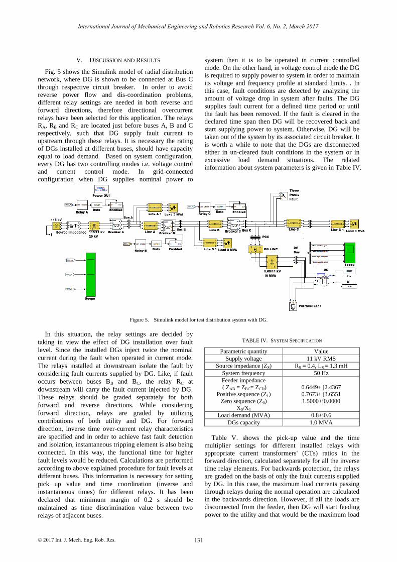
V. DISCUSSION AND RESULTS
Fig. 5 shows the Simulink model of radial distribution
network, where DG is shown to be connected at Bus C
through respective circuit breaker. In order to avoid
reverse power flow and dis-coordination problems,
different relay settings are needed in both reverse and
forward directions, therefore directional overcurrent
relays have been selected for this application. The relays
RA, RB and RC are located just before buses A, B and C
respectively, such that DG supply fault current to
upstream through these relays. It is necessary the rating
of DGs installed at different buses, should have capacity
equal to load demand. Based on system configuration,
every DG has two controlling modes i.e. voltage control
and current control mode. In grid-connected
configuration when DG supplies nominal power to
system then it is to be operated in current controlled
mode. On the other hand, in voltage control mode the DG
is required to supply power to system in order to maintain
its voltage and frequency profile at standard limits. . In
this case, fault conditions are detected by analyzing the
amount of voltage drop in system after faults. The DG
supplies fault current for a defined time period or until
the fault has been removed. If the fault is cleared in the
declared time span then DG will be recovered back and
start supplying power to system. Otherwise, DG will be
taken out of the system by its associated circuit breaker. It
is worth a while to note that the DGs are disconnected
either in un-cleared fault conditions in the system or in
excessive load demand situations. The related
information about system parameters is given in Table IV.
Figure 5. Simulink model for test distribution system with DG.
In this situation, the relay settings are decided by
taking in view the effect of DG installation over fault
level. Since the installed DGs inject twice the nominal
current during the fault when operated in current mode.
The relays installed at downstream isolate the fault by
considering fault currents supplied by DG. Like, if fault
occurs between buses BB and BC, the relay RC at
downstream will carry the fault current injected by DG.
These relays should be graded separately for both
forward and reverse directions. While considering
forward direction, relays are graded by utilizing
contributions of both utility and DG. For forward
direction, inverse time over-current relay characteristics
are specified and in order to achieve fast fault detection
and isolation, instantaneous tripping element is also being
connected. In this way, the functional time for higher
fault levels would be reduced. Calculations are performed
according to above explained procedure for fault levels at
different buses. This information is necessary for setting
pick up value and time coordination (inverse and
instantaneous times) for different relays. It has been
declared that minimum margin of 0.2 s should be
maintained as time discrimination value between two
relays of adjacent buses.
TABLE IV. SYSTEM SPECIFICATION
Parametric quantity Value
Supply voltage 11 kV RMS
Source impedance (ZS) RS = 0.4, LS = 1.3 mH
System frequency 50 Hz
Feeder impedance
( ZAB = ZBC= ZCD)
Positive sequence (Z1)
Zero sequence (Z0)
X0/X1
0.6449+ j2.4367
0.7673+ j3.6551
1.5000+j0.0000
Load demand (MVA) 0.8+j0.6
DGs capacity 1.0 MVA
Table V. shows the pick-up value and the time
multiplier settings for different installed relays with
appropriate current transformers' (CTs) ratios in the
forward direction, calculated separately for all the inverse
time relay elements. For backwards protection, the relays
are graded on the basis of only the fault currents supplied
by DG. In this case, the maximum load currents passing
through relays during the normal operation are calculated
in the backwards direction. However, if all the loads are
disconnected from the feeder, then DG will start feeding
power to the utility and that would be the maximum load
© 2017 Int. J. Mech. Eng. Rob. Res.
International Journal of Mechanical Engineering and Robotics Research Vol. 6, No. 2, March 2017
131

current value passing through the relays in the backwards
direction. Therefore, the pickup value for each relay
should be fixed above the maximum load currents so that
relays may not cause any malfunctioning and maintain
the safety margin too.
TABLE V. RELAY SETTINGS IN FORWARD DIRECTION
Relay CT ratio Pick-up
value
Time Multiplier Setting
(TMS)
RA 450/5 5.00 0.20
RB 400/5 4.50 0.15
RC 100/5 4.00 0.10
The maximum load current seen by RB is 292.7 A.
Therefore the relay RB is set to detect the faults which
have fault currents above the 439.05A by maintaining a
safety margin of 1.5 times the maximum load current.
Similarly, the maximum load current seen by RC is 52.8A
and this relay is set to detect the fault currents above
79.25 A. Time delay setting of RB for definite time
characteristic is selected as 0.1 s while it is 0.3 s for RC,
thereby allowing margin of 0.2 s for time discrimination
between two relays. Note that the same CTs are used in
both, forward and reverse directions. The selected relay
settings in reverse direction are given in Table VI.
TABLE VI. DEFINITE TIME RELAY ELEMENT SETTINGS IN REVERSE
DIRECTION
Relay CT ratio Pick-up
value
Time Setting
Multiplier (TMS)
RB 400/5 5.48 0.15
RC 100/5 3.96 0.35
Let consider a fault at point D in Fig. 5. The fault
current is 230 A and the fault should be considered
carefully by the relay RC. Since the fault current is higher
than the maximum fault current seen by Rc, therefore, Rc
should isolate this fault from the upstream side. The
standard inverse time relay element of Rc takes 0.286 s to
clear this fault. But if the fault occurs at point B, then the
fault current calculated is 1350 A and the relay RA should
isolate it from the utility supply. In this case, the relay RA
would take 0.453 s to clear the fault. This is the
disadvantage of inverse time relay element's grading. The
relay near to the source takes longer time to clear the
faults which have higher fault current levels. In such
cases, the problem is overcome by using the
instantaneous relay element of Rc which will clear the
fault instantly. The instantaneous settings for relays RA,
RB and Rc can be determined according to principle
explained in Section IV. Note that in the simulation, the
elements are set to trip after a time delay of 120 ms. The efficacy of deployed protection scheme has been
assured through MATLAB software for the different fault
scenarios at different fault locations. However, several
results for three-phase fault are presented in this section.
A three-phase fault was being created at the end of the
line between the two buses with the fault resistance of
0.01 Ω and the relay response time can be visualized
from Table VII. It can be seen that the relays deployed in
the system have the ability to isolate the faulted section
from the network. These results confirm that it is not
essential to disconnect the DG from a network if and if
the faulted section was isolated. If the fault was cleared
before the faulted section isolation (i.e. temporary fault)
the system could recover without disconnecting any DG,
thereby maximizing the DG benefits. The fault ride
through capability of DG played an important role to
achieve the fault isolation.
TABLE VII. RELAYS RESPONSE FOR DIFFERENT FAULT LOCATION
Fault Location Relay operating time (s)
RA RB RC
BA and BB 0.072 0.104 0.312
BB and BC 0.785 0.479 0.278
BC and BD 0.974 0.562 0.254
VI. CONCLUSION
Due to extensive use of electrical power distribution
system, the networks are operated at the edge of their
short circuit capacity, with small margin left for incoming
DG. Since the DG sources by their-selves contribute to
the fault incepted into network. Therefore installation of
DG is a risky task, because it badly affects the protection
scheme of the utility network where it is installed. DG
interconnection increases the short circuit capacity of
power network. Due to change of fault level, the
protection scheme designed for the network becomes
ineffective. In this research, we analyzed a radial
distribution feeder based on four buses, supplying power
different load sections. Calculations were performed for
short circuit capacity with and without the presence of
DG into the network at different sections of radial feeder.
According to such changes, over-current relay settings
were then premeditated through the graphical analysis.
Both the upstream and downstream defensive relays were
coordinated to segregate the shortcomings of the system.
An overcurrent relay protection scheme was proposed to
seclude the faulty section contingent upon the DG status.
The network restoration was then done by performing the
auto reclosing. The proposed protection strategies
amplified the DG advantages to the both utility and
clients, keeping up the various numbers of DG
associations, allowed in a high penetrative DG system.
VII. FUTURE RECOMMENDATIONS
Mitigating the impact of DG on the over-current
protection coordination by a manual readjustment of
overcurrent relay settings will not be effective when the
change of maximum and minimum DG power into the
system occurs quite often. Based on the short circuit
analysis, network may also be reconfigured depends upon
the new obtained values of fault current level. If not
implemented, the consequences may be either false
tripping or relay malfunctioning. One possible solution is
to install switching reactor, which can be brought into
service when the fault level of the system surpassed the
designated limit. Detailed analysis for network
reconfiguration with smart controlled reactors installed
© 2017 Int. J. Mech. Eng. Rob. Res.
International Journal of Mechanical Engineering and Robotics Research Vol. 6, No. 2, March 2017
132

on radial utility feeder with DG installation is left for
future task.
REFERENCES
[1] P. P. Barker and R. W. de Mello, “Determine the impact of
distribution generation on power systems: Part 1- radial
distribution systems,” Power Technologies, Inc., 2000. [2] S. Conti, “Analysis of distribution network protection issues in
presence of dispersed generation,” Electric Power Systems
Research, vol. 79, no. 1 pp. 49-56, 2009. [3] Amin-Zamani, Tarlochan-Sidhu, and Amir-Yazdani, “A strategy
for protection coordination in radial distribution networks with
distributed generators,” Power and Energy Society General Meeting, pp. 1-8, 2015.
[4] J. C. Gomez and M. M. Morcos, “Overcurrent coordination in systems with distributed generation,” Electric Power Components
and Systems, vol. 39, no. 6, pp. 576-589, 2013.
[5] IEC 60909-3, Short-Circuit Currents in Three-Phase a.c. Systems—Part 3: Currents During Two Separate Simultaneous
Line-to-Earth Short Circuits and Partial Short-Circuit Currents
Flowing Through Earth, 2003 [6] H. Zayandehroodi, A. Mohamed, H. Shareef, and M.
Mohammadjafari, “Impact of distributed generations on power
system protection performance,” International Journal of the Physical Sciences, vol. 6, no. 16, pp. 3873-3881, 2011.
[7] S. M. Brahma and A. A. Girgis, “Development of adaptive
protection scheme for distribution systems with high penetration of distributed generation,” IEEE Transaction Power Delivery, vol.
19, no. 1, pp. 56-63, 2004.
[8] M. T. Doyle, “Reviewing the impacts of distributed generation on distribution system protection,” Power Engineering Society
Summer Meeting, vol. 1, pp. 103-105, 2002.
[9] T. N. Boutsika and S. A. Papathanassiou, “Short-circuit calculations in networks with distributed generation,” Electric
Power Systems Research, vol. 78, no. 7, pp. 1181–1191, 2007.
[10] W. H. Kersting, “Radial distribution test feeders,” Power Engineering Society Winter Meeting, vol. 2, pp. 908-912, 2001.
[11] Amin-Zamani, Tarlochan-Sidhu, and Amir-Yazdani, “A strategy
for protection coordination in radial distribution networks with distributed generators,” Power and Energy Society General
Meeting, pp. 1-8, 2010
[12] N. Schaefer, T. Degner, A. Shustov, T. Keil, and J. Jaeger, “Adaptive protection system for distribution networks with
distributed energy resources,” in Proc. International Conference
on Developments in Power System Protection, 2014, pp. 1-5. [13] G. Carpinelli, G. Celli, F. Pilo, and A. Russo, “Distributed
generation relay setting and sizing under uncertainty,” Power Tech
Proceedings, vol. 4, p. 7, 2001. [14] K. Tuitemwong and S. Premrudeepreechacharn, “Expert system
for protective devices coordination in radial distribution network
with small power producers,” IEEE Lausanne Power Tech, pp. 1159-1164, 2017.
[15] IEC 60909-4, Short-circuit currents in three-phase a.c. systems—
Part 4: Examples for the calculation of short-circuit currents, 2000. [16] H. A. Asgarian, “A new optimal approach for coordination of
overcurrent relays in interconnected power systems,” IEEE Trans.
on Power Delivery, vol. 18, no. 2, pp. 430– 435, 2003. [17] J. Sadeh, “Optimal coordination of overcurrent relay in an
interconnected power system,” in Proc. Power System
Computation Conference, August 2005. [18] M. H. Hussan and S. R. A. Rahim, “Optimal overcurrent relay
coordination, a review,” Procedia Engineering, vol. 53, pp. 332-
336, 2015.
Mr. Sunny Katyara is a man of prestigious position who leads by his examples. Due to
best academic records he was awarded ICT
R&D fund scholarship in 2010. He received his B.E in Electrical Engineering from
Mehran UET Jamshoro Sindh. He was then
awarded scholarship by Erasmus Mundus to pursue higher studies in Renewable Energy
Systems at Wroclaw University of Science
and Technology Poland. He is also a certified Lab VIEW CLAD Engineer approved by National Instruments. He is
the active member of IEEE since 2014. His research interests include
Power Quality Assessments, Distributed Generation, modelling and analysis of different Power Quality scenarios, power system protection
and control, power system analysis and WSN technology. He has
authored more than 10 research papers. He is also the main author of
book published by German Scholar Press.
Dr. Lukasz Staszewski is a man of dynamic nature. He is a Ph.D Assistant at Wroclaw
University of Science and Technology Poland.
His research interests include Dynamic Thermal Line Rating (DTLR), Digital Signal
Processing (DSP) &Transmission and
distribution lines protection. He is the active member of IEEE. He has authored more than
12 research papers, both in international
conferences and impact factor journals.
Dr. Hyder Abbas Musavi is PhD and ME in
Telecommunication Engineering under HEC Scholarship and B.E. in Electronics
Engineering from Mehran University of
Engineering and Technology. He is currently serving as Dean Faculty of Engineering
Science and Technology Indus University
Karachi. Previously he was engaged as Chairman Department of Electrical and
Electronics Engineering Hamdard University
Karachi. In past he has served as Professor and Principal at Petroman- an Institute of Ministry of Information Technology and
Telecommunications, Government of Pakistan at its various campuses
for more than 10 years and had also remained Executive District Officer IT (EDO-IT) District Government Larkana. He has also served as
Business Development consultant and Senior Technical coordinator at
National Testing Service (NTS). To his credit are more than 25 research publications in national and international journals. He has attended
numerous international conferences as invited speaker. He is on review
board of two impact factor international journals. He has served as HEC Focal person for anti-plagiarism software, Head QEC, Coordinator
research activities, Coordinator PEC CPD activities, Coordinator IEEE
and IEEEP at Hamdard University. He is member of numerous national and international societies including member IEEEP Karachi local
council, IEEE, IEEE Computer society, IEEE Signal Processing Society,
IEEE Devices and Circuits Society, IEEE Communications Society etc.
Mr. Farhan Ali Soomro has done his
bachelor’s in Electrical Engineering from Mehran UET, Jamshoro. He has two year of
teaching experience at different Institutes. At
Present he is working as a Lab Engineer at Usman Institute of Technology Karachi,
Pakistan. He is also pursuing his master from
NED University Karachi, Pakistan. His research interests include renewable energy
sources; Phasor diagrams analysis of power
system networks and Protection Analysis of different fault conditions in
distributed power system. He is an active member of IEEE and
organizes many multifunctional events at his institute.
© 2017 Int. J. Mech. Eng. Rob. Res.
International Journal of Mechanical Engineering and Robotics Research Vol. 6, No. 2, March 2017
133