PARTS CATALOG - DCI Hollow Metal Door - DCI Hollow Metal ...
Upload
knuth-werkzeugmaschinen-gmbhCategory
view
254download
4description

MACHINE TOOLS
2012
SHEETMETAL WOrk
190
KP
A
B
DF
800
D
E
C
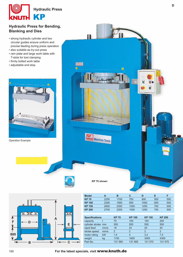
Hydraulic Press for Bending, Blanking and Dies
Hydraulic Press
• strong hydraulic cylinder and two circular guides ensure uniform and precise feeding during press operation
• also suitable as try-out press• ram plate and large work table with
T-slots for tool clamping• firmly bolted work table• adjustable end stop
KP 70 shown
Operation Example
Specifications KP 70 KP 100 KP 150 KP 200capacity t 70 100 150 200cylinder stroke mm 500 500 500 500rapid feed mm/s 18 22 20 20stroke speed mm/s 2 2 2 2motor rating kW 1,5 4 3,2 7,5weight kg 1100 1600 3000 4300Part No. 131 560 131 565 131 570 131 575
Model A B C D E FKP 70 2250 1700 700 900 500 500KP 100 2300 1900 850 1050 600 500KP 150 2600 2300 1000 1250 700 500KP 200 2700 2300 1500 1250 700 500
For the latest specials, visit www.knuth.de

191
KWPD
E
200
C
B
D
F
A
D
Ideal for craft shops, schools, and training facilities
Workshop Press
Standard Equipment: screw, pressure gauge, hand-wheel adjustable work table, 2 base plates, operator manual
KWP 50M shown
Specifications KWP 50 M KWP 80 Mcapacity t 50 80manual pump 1 1max. pressure bar 500 500 piston stroke mm 120 120 screw stroke mm 100 100 circular guides 2 2A mm 770 850 B mm 165 205 C mm 1020 1020 D mm 1910 2050 E mm 1000 1140 F mm 750 800 weight kg 230 330 Part No. 131 736 131 739
• rigid weldment design• reliable, highly accurate hydraulic
system, european mfg• pump lever for manual pressing
buildup• piston and return-spring reset• rigid base table with selecttable
heights, height adjusted by handwheel
• ram height also adjustable via screw • with guided cylinders
For any repair and installation work, e. g. :• removal and installation of press-fit
bearings, bolts and bushings• straightening beams, shafts, axles,
and sections• pressing and climping• load tests and weld sample testing• tool setup- material testing
Sh
ee
t M
eta
l W
ork
For more information, visit www.knuth.de
192
KNWPD
BD
F
G
I
H
K
A
EJC
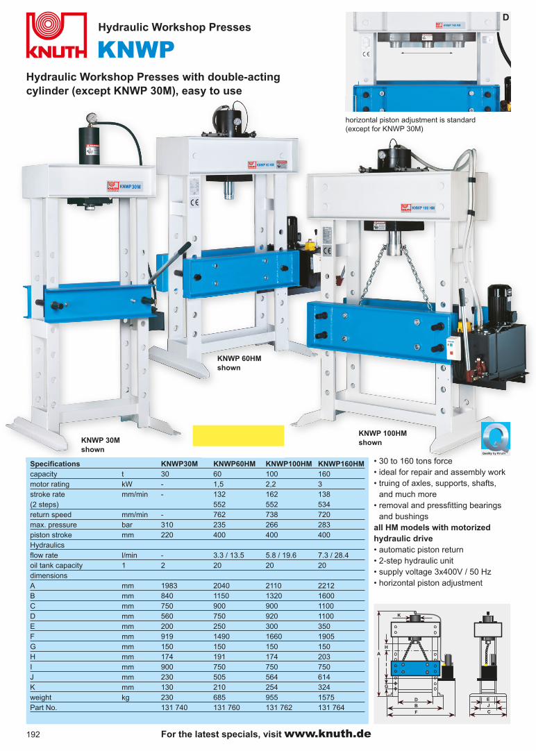
Hydraulic Workshop Presses with double-acting cylinder (except KNWP 30M), easy to use
Hydraulic Workshop Presses
Specifications KNWP30M KNWP60HM KNWP100HM KNWP160HMcapacity t 30 60 100 160motor rating kW - 1,5 2,2 3stroke rate mm/min - 132 162 138(2 steps) 552 552 534return speed mm/min - 762 738 720max. pressure bar 310 235 266 283piston stroke mm 220 400 400 400Hydraulics flow rate l/min - 3.3 / 13.5 5.8 / 19.6 7.3 / 28.4oil tank capacity 1 2 20 20 20 dimensions A mm 1983 2040 2110 2212B mm 840 1150 1320 1600C mm 750 900 900 1100D mm 560 750 920 1100E mm 200 250 300 350F mm 919 1490 1660 1905G mm 150 150 150 150H mm 174 191 174 203I mm 900 750 750 750J mm 230 505 564 614K mm 130 210 254 324weight kg 230 685 955 1575Part No. 131 740 131 760 131 762 131 764
KNWP 30M shown
KNWP 60HM shown
KNWP 100HM shown
• 30 to 160 tons force• ideal for repair and assembly work• truing of axles, supports, shafts,
and much more• removal and pressfitting bearings
and bushingsall HM models with motorizedhydraulic drive• automatic piston return• 2-step hydraulic unit • supply voltage 3x400V / 50 Hz• horizontal piston adjustment
horizontal piston adjustment is standard(except for KNWP 30M)
For the latest specials, visit www.knuth.de

193
HPKC
Die Press and Try-Out Press
Hydraulic C-Frame Press
Standard Equipment: ram plate and work table with T-slots, adjustable ram stroke, pressure gauge, hand lever operation, operator manual
Specifications HPK 40 HPK 70 HPK 100 HPK 150press force t 40 70 100 150cylinder stroke mm 500 500 500 500stroke speed mm/s 4 2 2 3rapid feed mm/s 29 20 22 20work table mm 700 x 500 700 x 500 800 x 600 800 x 600ram plate mm 700 x 350 700 x 350 700 x 350 800 x 400length x width mm 1000 x 1500 1000 x 1500 1200 x 1900 1500 x 2200height mm 2500 2500 2600 3000 weight kg 2050 2200 3400 5500Part No. 131 568 131 574 131 566 131 576
• strong hydraulic cylinder and two circular guides ensure uniform and precise feeding during press operation
• ideal for die pressing, blanking, bending, and much more
• semi-automatic with lever and micro-switch
• stroke length with quick adaption to next tool
• ram plate and work table with T-slots for tool clamping
• firmly bolted work table• advance and reverse jog operation
for easy machine set-up• stroke limit adjustable by
micro-switch• optimum table height• 2-stage hydraulic pump
Sh
ee
t M
eta
l W
ork
For more information, visit www.knuth.de

194
FKEX 60 SP
Specifications KEX 10 KEX 15 KEX 20 KEX 30 KEX 60 SPforce tons 10 15 20 30 60intermediate plate-to-ram dist. mm 130 172 196 215 285base plate-to-ram dist. mm 180 226 261 290 360stroke mm 40 40 50 60 100throat mm 150 200 200 200 250ram mount mm Ø 25 Ø 30 Ø 35 Ø 40 Ø 45stroke speed min-1 200 200 160 140 65stroke adjustment mm 10-40 10-40 10-50 10-60 10-100setup area mm 270x380 320x490 360x550 400x600 500x700table bore mm Ø 100 Ø 130 Ø 140 Ø 150 Ø 180flywheel mm Ø 540 Ø 585 Ø 680 Ø 710 Ø 685motor rating kW 0,75 1,5 2,2 3 5,5dimensions mm 760x770x1662 964x724x1726 1042x794x1856 790x1025x1965 1164x1320x2358weight kg 530 740 1150 1600 3500Part No. 130 070 130 071 131 390 131 392 131 395
with pneumatic clutch, 2-hand operation, light barrier KEX 15 P KEX 20 P KEX 30 PPart No. - 130 072 131 391 131 393 -
KEX 60 SP is shown
Powerful, safe, and rigid
Standard Equipment KEX 60 SP: mechanical overload protection, foot switch, two-hand control panel, automatic central lubrication, work space enclosure, light barier, pneumatic clutch, PLC Control, AC converter, infinitely variable stroke adjustment, operating tools, operator manual
with pneumatic clutch and light barrier protection for open tools
For more information, visit www.knuth.de
• torsion-resistant weldment• high-quality bearings ensure quiet, smooth operation• 4 guideways for precise stamp control• two-hand operation and foot pedal ensure maximum safety
and operator comfort• mechanical overload protection protects the machine from
damages caused by overload conditions• clutch and brake combination ensures low-maintenance
operation• the PLC detects and controls the crankshaft position• fully automated lubrication is controlled via SBS
independent from the stroke• the AC converter allows adjustment of various work speeds

195
F
KEX 10 • 15 • 20 • 30 • 60 SPCompact, powerful Single-Column Eccentric Presseswith forces in the range of 10 to 60 tons
Eccentric Shaft Press
• heavy-duty steel weldment• high stroke speed equals low-cost operation• ram guideway made of
brass/steel• foot switch• quiet operation• central lubrication
KEX 30 P is shownwith pneumatic clutch, 2-hand control, and light barrier
KEX 15 is shown
Standard Equipment for KEX 10 • 15 • 20 • 30: mechanical overload protection, foot switch, central lubrication, workspace enclosure, operating tools, operator manual
KEX 15 P, 20 P, 30 P:Same description as above, however, these models include a pneumatic clutch and 2-hand control and light barrier
Sh
ee
t M
eta
l W
ork
with standard clutch for closed tools (except KEX 60 SP)
For more information, visit www.knuth.de

196
Cybelec DNC 880 S
Specifications AHK F CNC 1540 2580 32160 32200 41160 41250 61250 62320Working area force tons 40 80 160 200 160 250 250 320brake length mm 1500 2500 3200 3200 4100 4100 6100 6200rear stop mm 600 600 600 600 600 600 600 600distance between columns mm 1200 2050 2700 2700 3600 3600 5600 5600throat mm 280 320 350 400 350 400 400 400max. stroke mm 380 450 480 520 480 520 520 520bending speed mm/sec 11 11 9.5 9 9.5 7.5 7.5 7.5rapid feed mm/sec 80 80 100 100 100 100 100 100return speed mm/sec 110 80 95 100 95 95 95 105motor rating kW 4 7.5 15 18.5 15 18.5 18.5 22Dimensions/Weight hydraulic tank volume Liter 145 240 440 700 600 930 1000 1000overall dimensions (LxWxH) mm 1700x1600
x2200
2700x1700
x2500
3300x1800
x2700
3300x2900
x2900
4300x1800
x2800
4300x2000
x2980
6300x2000
x3350
6400x2100
x3800
weight kg 2900 4700 10600 12500 12600 17000 24000 27600Part No. 182 970 182 971 182 972 182 980 182 973 182 981 182 982 182 983
• Folding depth adjustment via CNC-controlled directional control valve is monitored by linear scales
• Bending force is calculated via CNC control and can be integrated into the programs
• Automatic lower crowning with hydraulic drive• Low-maintenance rear stop with preloaded ball screws and
servo drives, plus automatic depth and height adjustment• Fissler Safety Technology ensures maximum operator
safety and optimum operation• Manual male die crowning within tool clamping is standard• Premium components made by renown manufacturers
ensure maximum machine reliability
• Intuitive programming with clear, easy to read color-coded field functions
• Complete programming of parts on one programming page• Comfortable operation via ergonomically tilted keyboard and
10“ TFT color monitor• Offline 2-D software to prepare production programs at the
PC, and to verify the feasibility of program editing at the machine
• Quick and easy modification of existing machining programs increases productivity
• 2D graphics for display and multiple simulations: optimum folding sequences - tools, plus the plate position inside the tools - collision warnings are displayed according to the user-defined criteria
• Supports over 20 languages
rear stops on two high-precision linear guides
For the latest specials, visit www.knuth.de
197
AHK F CNC D
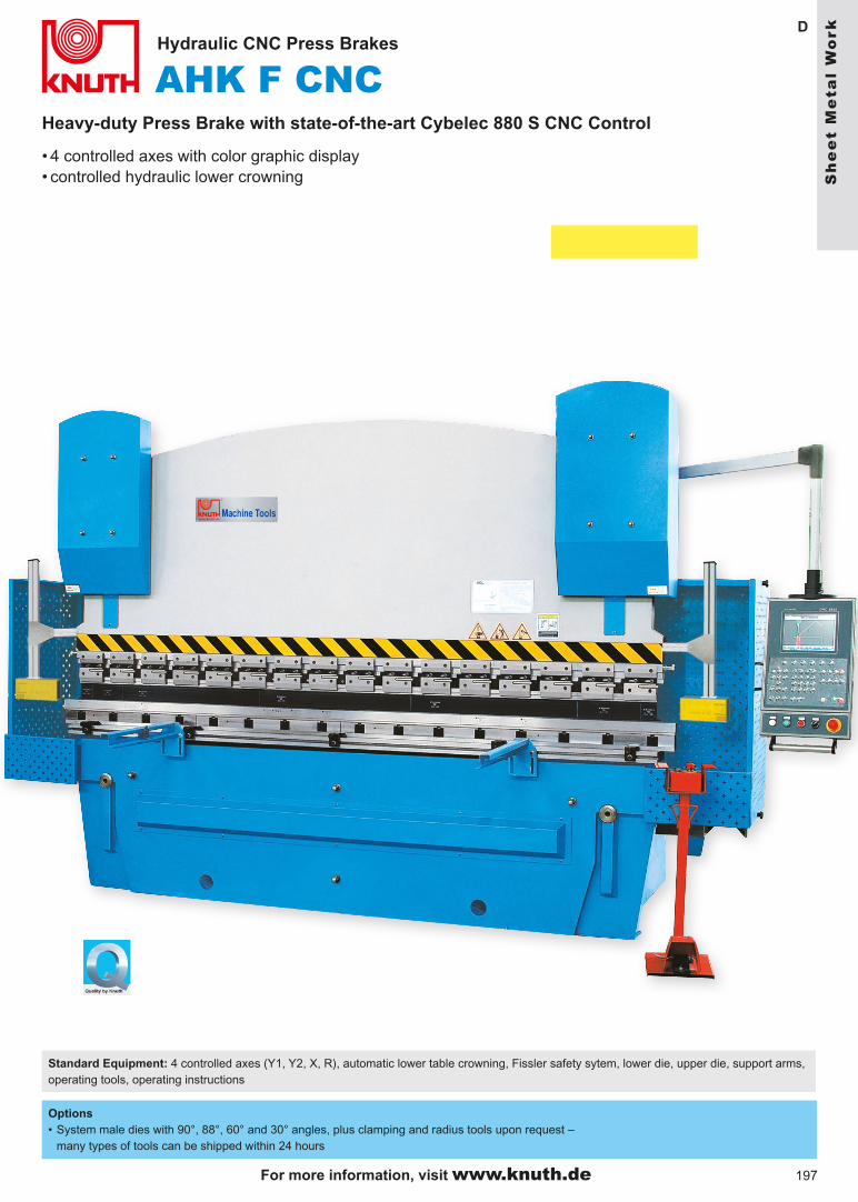
Heavy-duty Press Brake with state-of-the-art Cybelec 880 S CNC Control
Hydraulic CNC Press Brakes
Standard Equipment: 4 controlled axes (Y1, Y2, X, R), automatic lower table crowning, Fissler safety sytem, lower die, upper die, support arms, operating tools, operating instructions
• 4 controlled axes with color graphic display• controlled hydraulic lower crowning
Options • System male dies with 90°, 88°, 60° and 30° angles, plus clamping and radius tools upon request –
many types of tools can be shipped within 24 hours
Sh
ee
t M
eta
l W
ork
For more information, visit www.knuth.de

198
height-adjustable finger stopsquick-change system for male die
hydraulic cylinder for lower table crowning and manual micro-adjustment of rear stop (from 100 ton force upwards)
Specifications AHK A 1540 2250 25100 32125 32160 32200 32250 32320 41250 61250 61320
Working area
force tons 40 50 100 125 160 200 250 320 250 250 320
brake length mm 1500 2200 2500 3200 3200 3200 3200 3200 4100 6100 6100
rear stop mm 220 220 600 600 600 600 600 600 600 600 600
distance between columns mm 1200 1700 2000 2700 2700 2700 2700 2700 3300 5400 5400
throat mm 345 355 350 350 350 400 400 400 400 400 400
max. stroke mm 120 120 160 160 160 200 200 250 200 200 250
bending speed mm/sec 9,5 9,5 9 9 9 7.5 7.5 9 7.5 7.5 9
rapid feed mm/sec 60 60 80 80 80 80 80 80 80 80 80
return speed mm/sec 60 60 70 90 85 90 90 65 90 90 65
Drive Capacities
motor rating kW 4 4 7.5 11 11 15 18.5 22 18.5 18.5 22
Dimensions/Weight
hydraulic tank volume Liter 120 170 250 480 480 480 480 700 580 750 1000
dimensions Lengthwidthheight
mm 160012802080
230012902080
260016202500
330016802540
330017202540
341017802740
342018302810
340021503245
420018302810
620019003150
630023403600
weight kg 3000 3000 6700 8600 9600 12500 14500 17100 17600 24400 32000
Part No. 171 298 171 299 171 300 171 301 171 302 171 303 171 304 171 306 171 305 171 307 171 308
E. Position Indicator
For the latest specials, visit www.knuth.de
• The press brakes of this series are manufactured in standardized bulk series to ensure solid quality and significant cost savings
• The frame is made of solid steel weldment for overhead mounting
• Manual upper and hydraulic lower crowning ensure high manufacturing qualtiy.
• Large torsion shaft guarantees synchronism between both hydraulic cylinders.
• Motorized rear stop with manual micro-adjustments• Motors (from ABB) and hydraulic components from renown
manufacturers guarantee high machining quality and high reliability.
• Fulfills highest safety standards with Fissler Safety System, safety interlock, and protective covers
• Hardened hydraulic cylinders for long service life
199
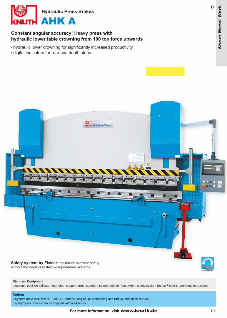
AHK A D
Constant angular accuracy! Heavy press with hydraulic lower table crowning from 100 ton force upwards
Hydraulic Press Brakes
Standard Equipment: electronic position indicator, rear stop, support arms, standard stamp and die, foot switch, safety system (make Fissler), operating instructions
• hydraulic lower crowning for significantly increased productivity• digital indicators for rear and depth stops
Options• System male dies with 90°, 88°, 60° and 30° angles, plus clamping and radius tools upon request –
many types of tools can be shipped within 24 hours
Safety system by Fissler: maximum operator safety without the need of restrictive light-barrier systems
Sh
ee
t M
eta
l W
ork
For more information, visit www.knuth.de

200
* P
late
ho
ld-u
p (
Mod
els
2504
F, 3
206
F, a
nd 4
006
F)
ensu
res
exac
t pos
ition
ing
of th
e pl
ate
at th
e re
ar s
top
whe
n us
ing
thin
mat
eria
ls
E-20+ control is shown
Sp
ecif
icat
ion
sK
HT
250
4 F
KH
T 3
206
FK
HT
321
0 F
KH
T 3
212
FK
HT
321
6 F
KH
T 3
220
FK
HT
400
6 F
KH
T 4
010
FK
HT
401
6 F
KH
T 6
012
FK
HT
601
6 F
Wo
rkin
g a
rea
plat
e th
ickn
ess
St 4
2 (m
ax.)
m
m4
610
1216
206
10
1612
16cu
tting
leng
th (
max
.)
mm
2500
3200
3200
3200
3200
3200
4000
4000
4000
6000
6000
rear
sto
p m
m56
056
076
076
076
096
056
076
080
080
010
00cu
t ang
le
1,5°
1,5°
1,5°
1,5°
2,5°
2,5°
1,5°
1,5°
2,5°
1,5°
2,5°
stro
kes
per
min
ute
stro
kes/
min
2518
159
75
159
55
4ho
ld-d
own
qty
1113
1515
18
1918
1922
2926
wor
k ta
ble
heig
ht
mm
800
800
810
810
810
850
800
810
800
800
1000
supp
ort a
rms
/ qua
ntity
mm
/ qt
y10
60 /
310
60 /
312
60 /
3 12
60 /
312
60 /
312
60 /
310
60 /
412
60 /
4 11
60 /
4 11
60 /
5 11
60 /
5 D
rive
Cap
acit
ies
m
otor
rat
ing
- hy
drau
lic p
ump
kW7,
57,
5 15
18,5
22
457,
515
22
18,5
22D
imen
sio
ns/
Wei
gh
t
hydr
aulic
tank
vol
ume
Lite
r24
0 29
0 42
0 40
040
0 43
038
0 41
045
045
045
0di
men
sion
s m
m31
00x1
470
x156
038
40x1
610
x162
040
80x1
980
x195
539
45x2
270
x205
541
00x2
300
x226
541
40x2
450
x230
546
30x1
850
x170
046
70x2
025
x192
048
50x2
300
x232
069
00x2
600
x264
068
20x2
720
x275
0w
eigh
t kg
4800
6600
1030
012
500
1550
022
000
8900
1250
019
500
3300
046
000
Par
t No.
133
500*
133
502*
133
504
133
506
133
508
133
510
133
512*
133
514
133
516
133
522
133
524
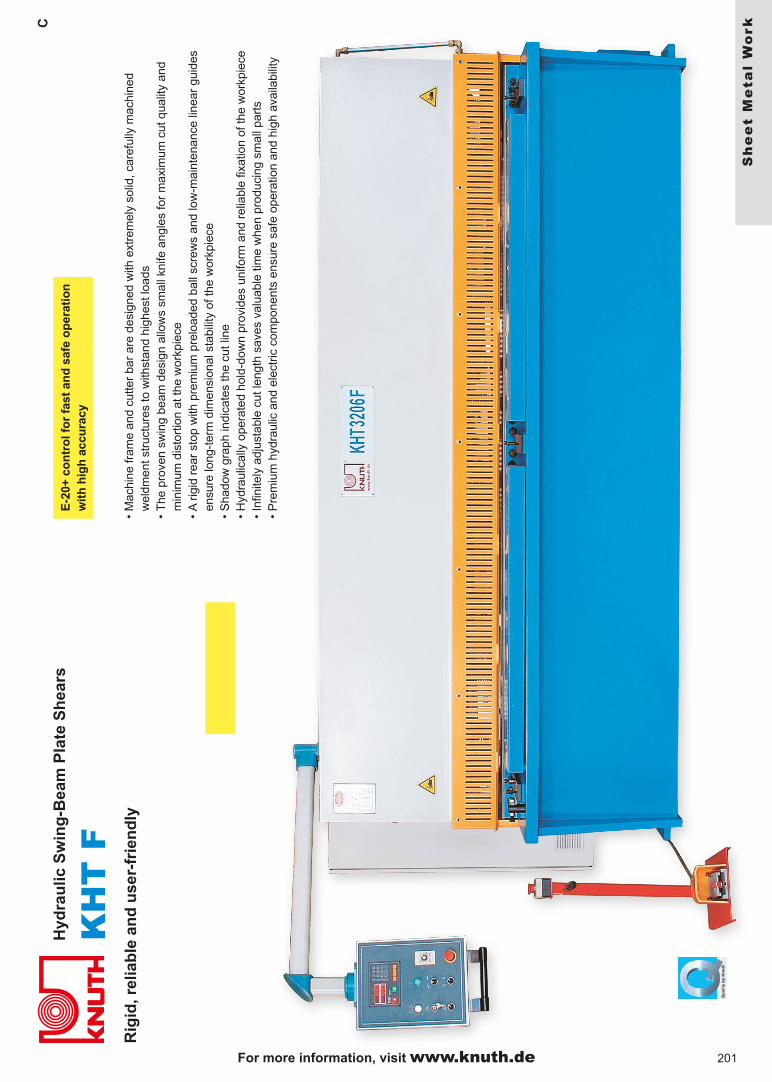
Sta
nd
ard
Eq
uip
men
t:
• E
-20+
con
trol
• po
wer
ed r
ear
stop
• m
otor
ized
ker
f adj
ustm
ent
• st
anda
rd u
pper
and
low
er k
nife
• 3
supp
ort a
rms
with
mea
surin
g sc
ale
• la
tera
l sto
p•
foot
sw
itch
• sh
adow
gra
ph d
ispl
ay o
f cut
line
• op
erat
or m
anua
l
For the latest specials, visit www.knuth.de
201
C
KH
T F
R
igid
, rel
iab
le a
nd
use
r-fr
ien
dly
Hyd
rau
lic S
win
g-B
eam
Pla
te S
hea
rsE
-20+
co
ntr
ol f
or
fast
an
d s
afe
op
erat
ion
w
ith
hig
h a
ccu
racy
• M
achi
ne fr
ame
and
cutte
r ba
r ar
e de
sign
ed w
ith e
xtre
mel
y so
lid, c
aref
ully
mac
hine
d w
eldm
ent s
truc
ture
s to
with
stan
d hi
ghes
t loa
ds•
The
pro
ven
swin
g be
am d
esig
n al
low
s sm
all k
nife
ang
les
for
max
imum
cut
qua
lity
and
min
imum
dis
tort
ion
at th
e w
orkp
iece
• A
rig
id r
ear
stop
with
pre
miu
m p
relo
aded
bal
l scr
ews
and
low
-mai
nten
ance
line
ar g
uide
sen
sure
long
-ter
m d
imen
sion
al s
tabi
lity
of th
e w
orkp
iece
• S
hado
w g
raph
indi
cate
s th
e cu
t lin
e•
Hyd
raul
ical
ly o
pera
ted
hold
-dow
n pr
ovid
es u
nifo
rm a
nd r
elia
ble
fixat
ion
of th
e w
orkp
iece
• In
finite
ly a
djus
tabl
e cu
t len
gth
save
s va
luab
le ti
me
whe
n pr
oduc
ing
smal
l par
ts•
Pre
miu
m h
ydra
ulic
and
ele
ctric
com
pone
nts
ensu
re s
afe
oper
atio
n an
d hi
gh a
vaila
bilit
y
Sh
ee
t M
eta
l W
ork
For more information, visit www.knuth.de

202
KM
TD
Mo
tori
zed
Sw
ing
-Bea
m S
hea
rs
Sp
ecif
icat
ion
s
KM
T 1
350
KM
T 2
004
KM
T 2
050
KM
T 2
504
KM
T 2
550
KM
T 3
050
max
. pla
te th
ickn
ess
ST
42
3
4
3
4
2,
5
2 m
ax. c
uttn
g le
ngth
m
m
1350
20
50
2050
25
50
2550
30
50
cutti
ng a
ngle
1° 3
0’
1° 3
0’
2° 1
2’
1° 3
0’
1° 3
0’
1° 3
0’nu
mbe
r of
str
okes
/ m
in. (
auto
mod
e)
35
42
35
42
35
35w
ork
tabl
e he
ight
m
m
850
85
0
850
85
0
850
85
0 m
ain
mot
or r
atin
g kW
3
7.
5
3
7.5
3
3
rear
sto
p m
m
450
75
0
450
75
0
450
45
0 di
men
sion
1700
x135
0 25
50x2
260
2400
x135
0 30
30x2
000
2900
x135
0 35
00x1
350
(LxW
xH)
m
m
x120
0
x133
0 x1
200
x1
330
x120
0 x1
200
wei
ght
kg
950
23
00
1150
32
00
1350
15
00
Par
t No.
130
234
132
238
130
235
132
239
130
236
130
237
Sta
nd
ard
Eq
uip
men
t: k
nife
set
, rea
r st
op, C
E-c
onfo
r-m
ing
safe
ty fe
atur
es, f
oot s
witc
h, r
ight
-han
d lo
ngitu
dina
l st
op, a
nd 2
sup
port
arm
s
• he
avy
stee
l wel
dmen
t con
stru
ctio
n fo
r m
axim
um
stab
ility
•
quie
t driv
e w
ith b
rake
mot
or; a
ll co
mpo
nent
s ru
n on
m
aint
enan
ce-f
ree
bear
ngs
• pr
alle
l kni
fe g
uide
s en
sure
hig
h cu
tting
pre
cisi
on•
high
-str
engt
h kn
ives
mad
e of
ste
el a
lloy,
har
dene
d an
d gr
ound
• si
de s
top
and
2 fr
ont s
uppo
rt a
rms
• se
lect
ion
switc
h fo
r si
ngle
and
con
tinuo
us s
trok
e•
hold
-dow
n sy
stem
with
slip
-res
iste
nt r
ubbe
r co
atin
g an
d en
gage
men
t saf
ety
guar
d
KM
T 1
350,
205
0, 2
550,
305
0•
cost
-effe
ctiv
e de
sign
with
pre
cisi
on-m
achi
ned
mac
hine
tabl
e •
man
ual r
ear
stop
450
mm
KM
T 2
004,
250
4•
extr
a he
avy-
duty
des
ign
with
hig
h-po
wer
mot
or
• su
ppor
t tab
le w
ith r
olle
r ba
lls fo
r ea
sy h
andl
ing
of
part
s•
mot
oriz
ed r
ear
stop
750
mm
, with
dig
ital d
ispl
ay•
adju
stab
le b
lade
gap
KM
T 2
504
sho
wn
Fo
r th
e la
test
sp
ecia
ls, v
isit
ww
w.k
nuth
.de
203
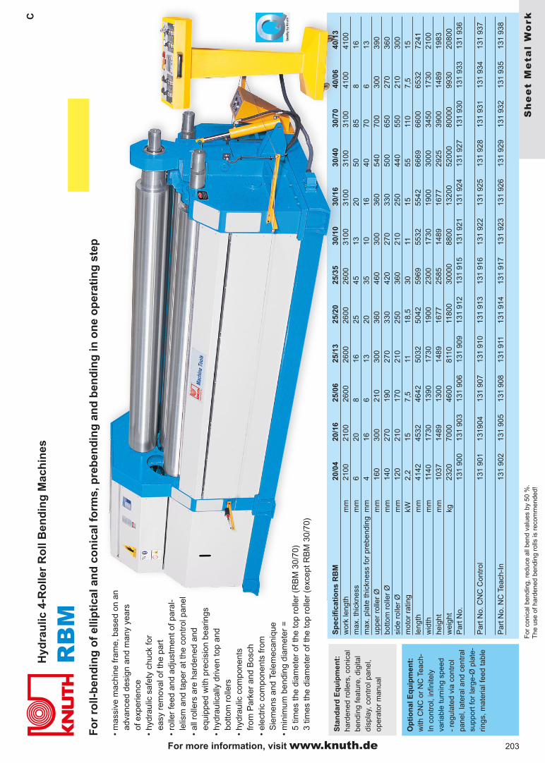
RB
M
C
Op
tio
nal
Eq
uip
men
t:
with
CN
C o
r N
C T
each
-In
con
trol
, inf
inite
ly
varia
ble
turn
ing
spee
d -
regu
late
d vi
a co
ntro
l pa
nel,
late
ral a
nd c
entr
al
supp
ort f
or la
rge-
Ø p
late
-rin
gs, m
ater
ial f
eed
tabl
e
Sta
nd
ard
Eq
uip
men
t:
hard
ened
rol
lers
, con
ical
be
ndin
g fe
atur
e, d
igita
l di
spla
y, c
ontr
ol p
anel
, op
erat
or m
anua
l
Sp
ecif
icat
ion
s R
BM
20/0
420
/16
25/0
625
/13
25/2
025
/35
30/1
030
/16
30/4
030
/70
40/0
640
/13
wor
k le
ngth
mm
2100
2100
2600
2600
2600
2600
3100
3100
3100
3100
4100
4100
max
. thi
ckne
ss
mm
620
816
2545
1320
5085
816
max
. pla
te th
ickn
ess
for
preb
endi
ngm
m4
166
1320
3510
1640
706
13up
per
rolle
r Ø
mm
160
300
210
300
360
460
300
360
540
700
300
390
botto
m r
olle
r Ø
mm
140
270
190
270
330
420
270
330
500
650
270
360
side
rol
ler
Øm
m12
021
017
021
025
036
021
025
044
055
021
030
0m
otor
rat
ing
kW2,
215
7,5
1118
,530
1115
5511
07,
515
leng
th
mm
4142
4532
4642
5032
5042
5969
5532
5542
6669
6600
6532
7241
wid
thm
m11
4017
3013
9017
3019
0023
0017
3019
0030
0034
5017
3021
00he
ight
mm
1037
1489
1300
1489
1677
2585
1489
1677
2925
3900
1489
1983
wei
ght
kg23
2070
0046
0081
1011
800
3000
088
0013
200
5200
080
000
9930
2080
0P
art N
o.13
1 90
013
1 90
313
1 90
613
1 90
913
1 91
213
1 91
513
1 92
113
1 92
413
1 92
713
1 93
013
1 93
313
1 93
6
Par
t No.
CN
C C
ontr
ol13
1 90
113
1904
131
907
131
910
131
913
131
916
131
922
131
925
131
928
131
931
131
934
131
937
Par
t No.
NC
Tea
ch-I
n13
1 90
213
1 90
513
1 90
813
1 91
113
1 91
413
1 91
713
1 92
313
1 92
613
1 92
913
1 93
213
1 93
513
1 93
8
Fo
r ro
ll-b
end
ing
of
ellip
tica
l an
d c
on
ical
fo
rms,
pre
ben
din
g a
nd
ben
din
g in
on
e o
per
atin
g s
tep
• m
assi
ve m
achi
ne fr
ame,
bas
ed o
n an
ad
vanc
ed d
esig
n an
d m
any
year
s of
exp
erie
nce
• hy
drau
lic s
afet
y ch
uck
for
easy
rem
oval
of t
he p
art
• ro
ller
feed
and
adj
ustm
ent o
f par
al-
lelis
m a
nd ta
per
at th
e co
ntro
l pan
el•
all r
olle
rs a
re h
arde
ned
and
equi
pped
with
pre
cisi
on b
earin
gs•
hydr
aulic
ally
driv
en to
p an
d bo
ttom
rol
lers
• hy
drau
lic c
ompo
nent
s fr
om P
arke
r an
d B
osch
• el
ectr
ic c
ompo
nent
s fr
om
Sie
men
s an
d Te
lem
ecan
ique
• m
inim
um b
endi
ng d
iam
eter
=
5 tim
es th
e di
amet
er o
f the
top
rolle
r (R
BM
30/
70)
3 tim
es th
e di
amet
er o
f the
top
rolle
r (e
xcep
t RB
M 3
0/70
)
For
con
ical
ben
ding
, red
uce
all b
end
valu
es b
y 50
%.
The
use
of h
arde
ned
bend
ing
rolls
is r
ecom
men
ded!
Hyd
rau
lic 4
-Ro
ller
Ro
ll B
end
ing
Mac
hin
es
Sh
ee
t M
eta
l W
ork
For more information, visit www.knuth.de
204
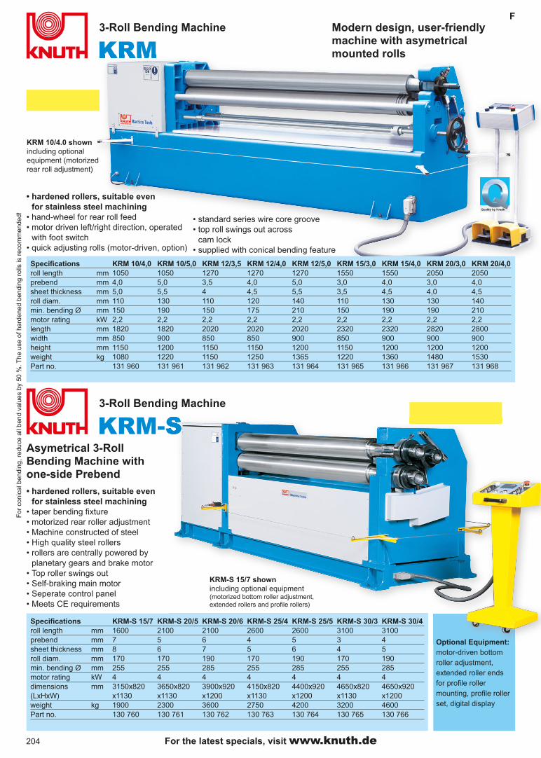
KRMF
KRM-S
Modern design, user-friendly machine with asymetrical mounted rolls
3-Roll Bending Machine
Optional Equipment: motor-driven bottom roller adjustment, extended roller ends for profile roller mounting, profile roller set, digital display
Specifications KRM-S 15/7 KRM-S 20/5 KRM-S 20/6 KRM-S 25/4 KRM-S 25/5 KRM-S 30/3 KRM-S 30/4roll length mm 1600 2100 2100 2600 2600 3100 3100prebend mm 7 5 6 4 5 3 4sheet thickness mm 8 6 7 5 6 4 5roll diam. mm 170 170 190 170 190 170 190min. bending Ø mm 255 255 285 255 285 255 285motor rating kW 4 4 4 4 4 4 4dimensions mm 3150x820 3650x820 3900x920 4150x820 4400x920 4650x820 4650x920(LxHxW) x1130 x1130 x1200 x1130 x1200 x1130 x1200weight kg 1900 2300 3600 2750 4200 3200 4600Part no. 130 760 130 761 130 762 130 763 130 764 130 765 130 766
Asymetrical 3-Roll Bending Machine with one-side Prebend
3-Roll Bending Machine
Specifications KRM 10/4,0 KRM 10/5,0 KRM 12/3,5 KRM 12/4,0 KRM 12/5,0 KRM 15/3,0 KRM 15/4,0 KRM 20/3,0 KRM 20/4,0roll length mm 1050 1050 1270 1270 1270 1550 1550 2050 2050prebend mm 4,0 5,0 3,5 4,0 5,0 3,0 4,0 3,0 4,0sheet thickness mm 5,0 5,5 4 4,5 5,5 3,5 4,5 4,0 4,5roll diam. mm 110 130 110 120 140 110 130 130 140min. bending Ø mm 150 190 150 175 210 150 190 190 210motor rating kW 2,2 2,2 2,2 2,2 2,2 2,2 2,2 2,2 2,2length mm 1820 1820 2020 2020 2020 2320 2320 2820 2800width mm 850 900 850 850 900 850 900 900 900height mm 1150 1200 1150 1150 1200 1150 1200 1200 1200weight kg 1080 1220 1150 1250 1365 1220 1360 1480 1530Part no. 131 960 131 961 131 962 131 963 131 964 131 965 131 966 131 967 131 968
• hardened rollers, suitable even for stainless steel machining
• taper bending fixture• motorized rear roller adjustment• Machine constructed of steel• High quality steel rollers• rollers are centrally powered by
planetary gears and brake motor• Top roller swings out• Self-braking main motor• Seperate control panel• Meets CE requirements
• hardened rollers, suitable even for stainless steel machining
• hand-wheel for rear roll feed • motor driven left/right direction, operated
with foot switch• quick adjusting rolls (motor-driven, option)
• standard series wire core groove• top roll swings out across
cam lock• supplied with conical bending feature
KRM 10/4.0 shownincluding optional equipment (motorized rear roll adjustment)
KRM-S 15/7 shownincluding optional equipment (motorized bottom roller adjustment, extended rollers and profile rollers)
For
con
ical
ben
ding
, red
uce
all b
end
valu
es b
y 50
%. T
he u
se o
f har
dene
d be
ndin
g ro
lls is
rec
omm
ende
d!
For the latest specials, visit www.knuth.de
205
F
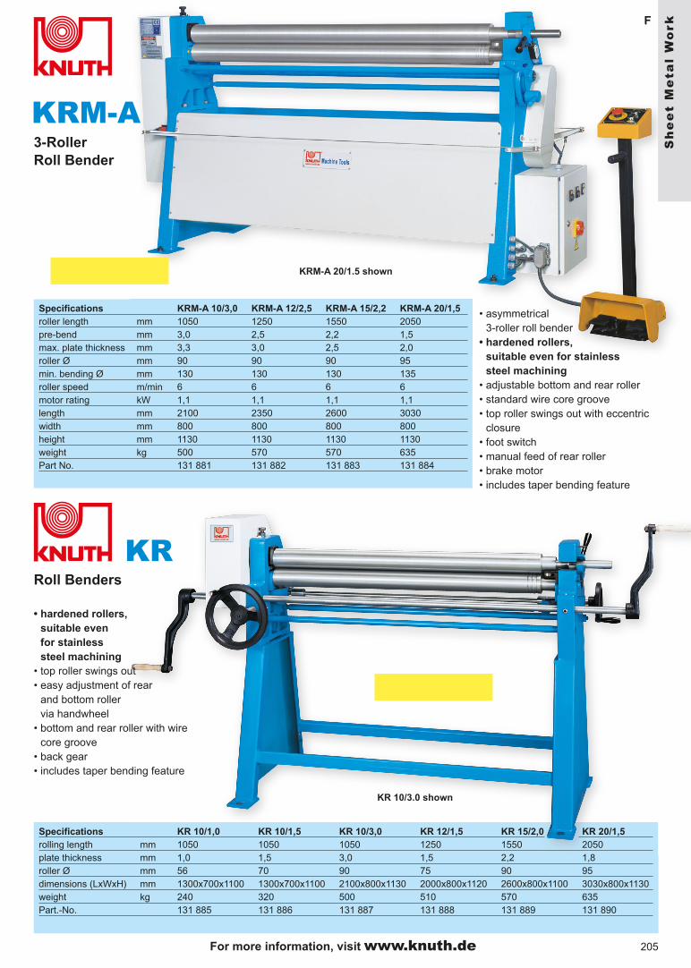
KR
F
KRM-A3-RollerRoll Bender
• hardened rollers, suitable even for stainless steel machining
• top roller swings out• easy adjustment of rear
and bottom roller via handwheel
• bottom and rear roller with wire core groove
• back gear• includes taper bending feature
Roll Benders
• asymmetrical 3-roller roll bender
• hardened rollers, suitable even for stainless steel machining
• adjustable bottom and rear roller• standard wire core groove• top roller swings out with eccentric
closure • foot switch• manual feed of rear roller• brake motor• includes taper bending feature
KRM-A 20/1.5 shown
KR 10/3.0 shown
Specifications KRM-A 10/3,0 KRM-A 12/2,5 KRM-A 15/2,2 KRM-A 20/1,5roller length mm 1050 1250 1550 2050 pre-bend mm 3,0 2,5 2,2 1,5max. plate thickness mm 3,3 3,0 2,5 2,0roller Ø mm 90 90 90 95min. bending Ø mm 130 130 130 135roller speed m/min 6 6 6 6motor rating kW 1,1 1,1 1,1 1,1length mm 2100 2350 2600 3030width mm 800 800 800 800height mm 1130 1130 1130 1130weight kg 500 570 570 635Part No. 131 881 131 882 131 883 131 884
Specifications KR 10/1,0 KR 10/1,5 KR 10/3,0 KR 12/1,5 KR 15/2,0 KR 20/1,5rolling length mm 1050 1050 1050 1250 1550 2050 plate thickness mm 1,0 1,5 3,0 1,5 2,2 1,8roller Ø mm 56 70 90 75 90 95dimensions (LxWxH) mm 1300x700x1100 1300x700x1100 2100x800x1130 2000x800x1120 2600x800x1100 3030x800x1130weight kg 240 320 500 510 570 635Part.-No. 131 885 131 886 131 887 131 888 131 889 131 890
Sh
ee
t M
eta
l W
ork
For more information, visit www.knuth.de
206
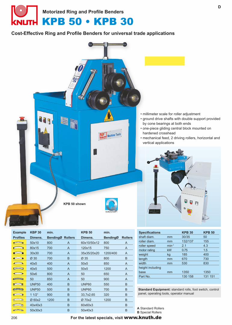
KPB 50 • KPB 30D
Cost-Effective Ring and Profile Benders for universal trade applications
Motorized Ring and Profile Benders
Standard Equipment: standard rolls, foot switch, control panel, operating tools, operator manual
• millimeter scale for roller adjustment• ground drive shafts with double support provided
by cone bearings at both ends• one-piece gliding central block mounted on
hardened crosshead• mechanical feed, 2 driving rollers, horizontal and
vertical applications
KPB 50 shown
A Standard Rollers B Special Rollers
Example KBP 30 min. KPB 50 min.
Profiles Dimens. BendingØ Rollers Dimens. BendingØ Rollers
50x10 800 A 60x10/50x12 800 A
80x15 700 A 120x15 750 A
30x30 700 A 35x35/20x20 1200/400 A
Ø 30 700 B Ø 35 800 B
40x5 400 A 50x5 850 A
40x5 500 A 50x5 1200 A
50x6 800 A 50 650 A
50 850 A 50 900 A
UNP50 400 B UNP60 550 B
UNP50 500 B UNP60 700 B
1 1/2“ 900 B 33,7x2,65 320 B
Ø 60x2 1200 B Ø 70x2 1200 B
40x40x3 B 60x60x3 B
50x30x3 B 50x40x3 B
Specifications KPB 30 KPB 50shaft diam. mm 30/35 50 roller diam. mm 132/137 155 roller speed min-1 2.1 4.3 motor rating kW 0.75 1.5 weight kg 185 400 length mm 670 730 width mm 530 830 height includingbase mm 1350 1350Part No. 130 158 131 151
For the latest specials, visit www.knuth.de
207
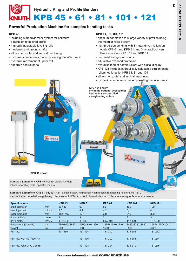
KPB 45 • 61 • 81 • 101 • 121D
Hydraulic Ring and Profile Benders
KPB 101 shown including optional accessories hydraulically controlled straightening rollers
Powerful Production Machine for complex bending tasks
Specifications KPB 45 KPB 61 KPB 81 KPB 101 KPB 121shaft diameter mm 50 / 40 60 80 100 120bending speed m/min 3,3 6,4 4,2 5,4 4 roller diameter mm 152 / 162 177 245 315 390 driven rollers quant. 3 3 3 3 3 drive motor kW / V 1,5 / 400 4 / 400 5,5 / 400 11 / 400 15 / 400dimensions (LxWxH) mm 780x950x1650 1260x940x1390 1375x1040x1540 1435x1220x1680 1985x1450x2040 weight kg 500 1080 1600 3500 4720 Part No. 131 150 131 194 131 200 131 206 131 212 Part No. with NC Teach-In - 131 196 131 202 131 208 131 214 Part No. with CNC Control - 131 198 131 204 131 210 131 216
Standard Equipment KPB 45: control panel, standard rollers, operating tools, operator manual
KPB 45• including a modular roller system for optimum
adaptation to desired profile• manually adjustable leveling rolls• hardened and ground shafts• allows horizontal and vertical machining• hydraulic components made by leading manufacturers• hydraulic movement of upper roll• separate control panel
KPB 61, 81, 101, 121• optimum adaptation to a large variety of profiles using
the modular roller system • high-precision bending with 3 motor-driven rollers on
models KPB 61 and KPB 81, and 3 hydraulic-driven rollers on models KPB 101 and KPB 121
• hardened and ground shafts• adjustable overload protection• hydraulic feed of bottom rollers with digital display• KPB 121 includes hydraulically adjustable straightening
rollers; optional for KPB 61, 81 and 101• allows horizontal and vertical machining• hydraulic components made by leading manufacturers
Standard Equipment KPB 61, 81, 101, 121: digital display, hydraulically controlled straightening rollers (KPB 121), mechanically controlled straightening rollers (except KPB 121), control panel, standard rollers, operating tools, operator manual
KPB 45 shown
For more information, visit www.knuth.de
Sh
ee
t M
eta
l W
ork

208
B
Specifications - HPS 45 D 55/110 D 80/150 D 110/180 DPunch presspress force t 45 55 80 110max. capacity mm Ø 27 x 13 Ø 40 x 10 Ø 40 x 14 Ø 40 x 20diameter x thickness mm Ø 18 x 18 Ø 20 x 20 Ø 24 x 24 Ø 28 x 28throat mm 160 250 300 610stroke mm 21 60 70 80strokes/min (20 mm) 20 37 38 28table size mm 450 x 160 550 x 250 550 x 300 550 x 610working height mm 1010 1080 1195 1260Steel cutterscutting capacity, flat- max. thickness mm 200 x 13 200 x 20 300 x 20 400 x 20- max. width mm 300 x 10 300 x 15 450 x 15 600 x 15knife length mm 305 305 475 605cutting capacity, round mm 30 40 45 50cutting capacity, square mm 30 40 45 50working height mm 1010 890 1032 1085Profile cuttercutting capacity 90º mm 80 x 80 x 8 120 x 120 x 10 130 x 130 x 13 152 x 152 x 13cutting capacity 45º mm - 70 x 70 x 7 70 x 70 x 7 70 x 70 x 7working height mm 1020 1100 1250 1305Notchermaterial thickness mm 7 10 12 7depth V90xWidthxThickn mm 40 x 40 x 7 42 x 42 x 10 52 x 52 x 12 52 x 52 x 13motor rating kW 3 5,5 11 11dimensions (LxWxH) mm 1460 x 1400
x 16201480 x 1800 x 1730
2025 x 1780 x 2700
2560 x 1790x 2250
weight kg 810 1300 2700 3750Part No. 130 170 130 172 130 174 130 176
structural steel station
steel plate station
angle steel station
hole punch station
notching station
• HPS 45 D is a 1-cylinder version• Models HPS 55/110 D, HPS 80/150 D and HPS 110/180 D provide 2
hydraulic cylinders for simultaneous work at 2 stations
HPS 45 D shown
For the latest specials, visit www.knuth.de

209
HPSB
Universal Machining Operations at 5 Work Stations
• Punching• Cutting • Notching
Hydraulic Profile Steel Cutters
Flat Steel Cutters• lower knife provides 4 cutting edges• table with angular and linear stopsAngular Profile Steel Cutters• rear stop adjustable up to 1000 mm
- manual operation on model HPS 45 D, automatic cut activation on all other models
Rod Steel Station• hold-down for round and square steel• rear stop at 1,000 mmNotching Station• table with scales and stopHole Punch Station• for punching sheet metals, flat steel
and U-section steel
• heavy-duty table ensures high-quality punching results
• models HPS 110/180 D provide an extra-wide throat
• infinitely variable stroke adjustment• including adapter for „Peddinghaus“
stamps and dies (only HPSD) • hydraulic overload valves
HPS 80/150 D shown
Sh
ee
t M
eta
l W
ork
For more information, visit www.knuth.de

210
KHS E 1000
SB E 2060/2
H
F
Manual Shears
Folding Machine
• cast iron design• rigid and durable
structure• versatile applications
Specifications SB E 2060/2effective length mm 2060 max. thickness mm 2max. bending radius 135°top beam travel mm 210adj. lower bending beam mm 100dimensions (LxWxH) mm 2900 x 650 x 1740weight kg 1750Part no. 131 336
Specifications KHS E 1000max. sheet thickn. mm 1,5work length mm 1040table mm 640x1000stop mm 0-600height mm 1500width mm 1000length mm 1300weight kg 460Part no. 132 036
• large dimensions steelplates sheets can be pushed through
For the latest specials, visit www.knuth.de

211
F
SBS E 2020/2,0
SBS 1020/2,5 • SBS 1270/2,0
Folding Machine
• Segmenting: 25, 30, 35, 40, 45, 50, 75, 100, 150, 200, 200, 270, 400 and 400 mm
• Lever for the swivel movement of the bending beam
Specifications SBS E 2020/2,0max. bending capac. ST 45 mm 2,0max. bending length mm 2020inf. var. bending angle 0 - 135° working height mm 910dimensions (LxWxH) mm 2565 x 560 x 1265Weight kg 1020Part No. 131 367
Folding Machines
Specifications SBS 1020/2.5 SBS 1270/2.0max. folding cap.St 42 mm 2.5 2.0 max. folding length mm 1020 1270 max. folding angle 135° 135°dimensions (LxWxH) mm 1348x850x1175 1598x900x1175 weight kg 285 330 Part No. 131 364 131 363
• for formed component bending• compression spring for top beam
counterbalance• cam lock and rebound spring for bending
beam counterbalance• bow handle for bending beam rotation• adjustable bending angle stop with scale
up to 135°• segmented top beam tools• segment sizes
- SBS 1020/2.5: 25, 30, 35, 40, 45, 50, 75, 100, 150, 200, 270 mm- SBS 1270/2.0: 25, 30, 35, 40, 45, 50, 75, 100, 150, 200, 250, 270 mm
Sh
ee
t M
eta
l W
ork
For more information, visit www.knuth.de
212212
F
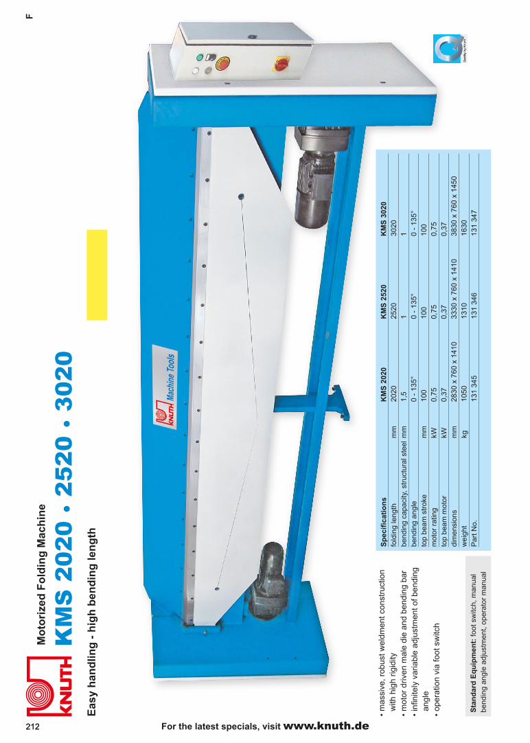
KM
S 2
020
• 25
20 •
302
0
For the latest specials, visit www.knuth.de
Eas
y h
and
ling
- h
igh
ben
din
g le
ng
th
Sta
nd
ard
Eq
uip
men
t: fo
ot s
witc
h, m
anua
l be
ndin
g an
gle
adju
stm
ent,
oper
ator
man
ual
• m
assi
ve, r
obus
t wel
dmen
t con
stru
ctio
nw
ith h
igh
rigid
ity•
mot
or d
riven
mal
e di
e an
d be
ndin
g ba
r•
infin
itely
var
iabl
e ad
just
men
t of b
endi
ng
angl
e•
oper
atio
n vi
a fo
ot s
witc
h
Mo
tori
zed
Fo
ldin
g M
ach
ine
Sp
ecif
icat
ion
sK
MS
202
0K
MS
252
0K
MS
302
0fo
ldin
g le
ngth
mm
2020
2520
3020
bend
ing
capa
city
, str
uctu
ral s
teel
mm
1,5
11
bend
ing
angl
e 0
- 13
5°0
- 13
5°0
- 13
5°to
p be
am s
trok
em
m10
010
010
0m
otor
rat
ing
kW0,
750,
750,
75to
p be
am m
otor
kW0,
370,
370,
37di
men
sion
sm
m28
30 x
760
x 1
410
3330
x 7
60 x
141
038
30 x
760
x 1
450
wei
ght
kg10
5013
1016
30P
art N
o.13
1 34
513
1 34
613
1 34
7

KW 100
5 THP 15
213
H
• sturdy design for screw- mounting on workbench• infintiely variable bending stop adjustment• with eccenter quick-clamp for streamlined operation• bending angle read-out up to 120°• bending angle stop for high repeatability• ideal for repair shops and metal working shops
Standard Equipment: angle stop, bending plates, bending lever, material stop
Specifications Model KW 100weight kg 38dimensions (LxWxH) mm 380 x 250 x 260Part No. 129 122
Cold Hot Flat steel mm 100 x 5 100 x 15 or mm 60 x 8 100 x 12 Round steel mm 18 30 Square steel mm 16 x 16 30 x 30 Flat copper 100 x 12 -
for exact cold and hot bending of flat, round, and square steel
Angle Iron Bender
for angle, round, loop, and coil bending
Universal Bender
• to produce grids, doors, gates, balcony railings, patio furniture as well as rod iron lamps.
• with hardened bending segments• suitable for steel, brass, copper, and aluminum• round bar up to 15 mm• square bar up to 13 mm, flat bar up to 30 x 8 mmPart No. 130 127
Arbor Press
• for press-fitting and pulling bearings
• aligning, bending and broaching
• basePart no. 123 952
Hydraulic Presses
• 15 t• piston bore 80 mm• pressure 300 kg/cm2
• ram to table distance 500 mm• table 300 x 300 mm• height 1060 mm• weight 145 kgPart no. 130 042 1 T - force 5 kN,
workpiece size max. 147 mmPart no. 109 536
2 T - force 10 kN,workpiece size max. 215 mmPart no. 109 537
3 T - force 15 kN,workpiece size max. 317 mmPart no. 109 538 -
5 T - force 20 kN, workpiece size max. 400 mmPart no. 109 540
Sh
ee
t M
eta
l W
ork
For more information, visit www.knuth.de

214
3 IN 1H
One machine for Cutting, Folding, and Roll Bending
Specifications 3 IN 1 - 305 3 IN 1 - 760 3 IN 1 - 1000max. plate length mm 305 760 1000max. plate thickness mm 0,8 0,8 0,8roller diameter mm 39 39 42dim. (LxWxH) mm 650x540x540 970x450x680 1420x560x750weight kg 45 120 260Part No. 110 050 110 060 110 047
Price does not include base
3 IN 1 - 1000 shown
• Ideal combination machine for sheet metal machining up to a length of 1000 mm and a thickness of 0.8 mm
• cutting stop• roll bending starting with a diameter of 40 mm,
adjustable, 1000 mm opening• folding with a max. angle of 180°
press segments 25 - 750 mm• adjustable rear stop Part No. 110 047
Hydraulic Tube Bender 1/2“ - 2“
• 10 to pressure• 6 bending segments• 3-leg standPart no. 129 112
For the latest specials, visit www.knuth.de
215
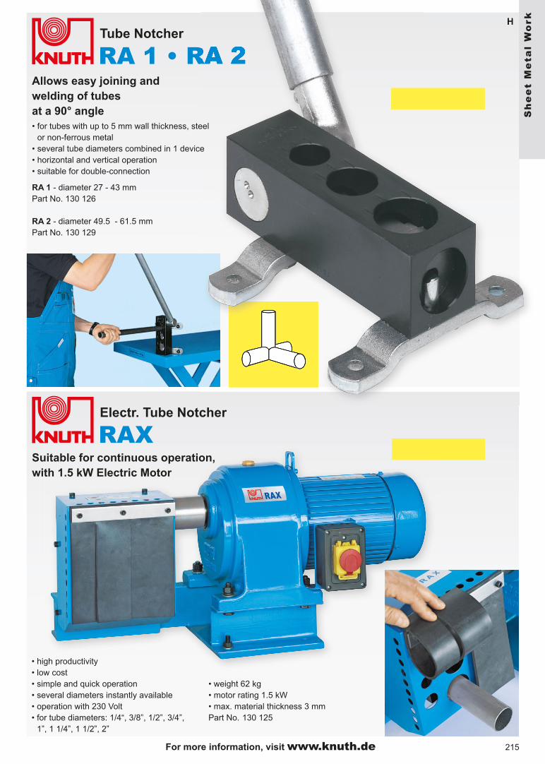
RA 1 • RA 2H
F
RAX
H
Allows easy joining andwelding of tubesat a 90° angle
Tube Notcher
• for tubes with up to 5 mm wall thickness, steel or non-ferrous metal
• several tube diameters combined in 1 device• horizontal and vertical operation• suitable for double-connection
RA 1 - diameter 27 - 43 mmPart No. 130 126
RA 2 - diameter 49.5 - 61.5 mmPart No. 130 129
Electr. Tube Notcher
Suitable for continuous operation, with 1.5 kW Electric Motor
• high productivity • low cost• simple and quick operation• several diameters instantly available• operation with 230 Volt• for tube diameters: 1/4“, 3/8”, 1/2”, 3/4”,
1”, 1 1/4”, 1 1/2”, 2”
• weight 62 kg• motor rating 1.5 kW• max. material thickness 3 mmPart No. 130 125
Sh
ee
t M
eta
l W
ork
For more information, visit www.knuth.de
216
AKMH
RGM
216
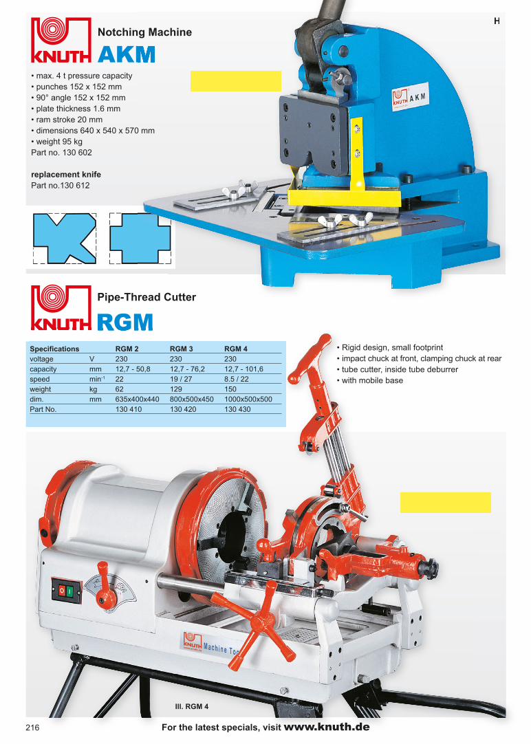
HNotching Machine
Pipe-Thread Cutter
• max. 4 t pressure capacity• punches 152 x 152 mm• 90° angle 152 x 152 mm• plate thickness 1.6 mm• ram stroke 20 mm• dimensions 640 x 540 x 570 mm• weight 95 kgPart no. 130 602
replacement knifePart no.130 612
• Rigid design, small footprint• impact chuck at front, clamping chuck at rear• tube cutter, inside tube deburrer• with mobile base
Ill. RGM 4
For the latest specials, visit www.knuth.de
Specifications RGM 2 RGM 3 RGM 4voltage V 230 230 230capacity mm 12,7 - 50,8 12,7 - 76,2 12,7 - 101,6speed min-1 22 19 / 27 8.5 / 22weight kg 62 129 150dim. mm 635x400x440 800x500x450 1000x500x500Part No. 130 410 130 420 130 430

217
H
Hydraulic Machine Lift
Load Guidance
Hydraulic Machine Lift H 3 H 8load capacity t 3 8lifting range mm 15 - 240 25 - 295intrinsic weight kg 21,5 28Part No. 140 305 140 310
Load Guidance L 6 L 12load capacity t 6 12number of rollers pcs. 8 8roller material plastic steeldimensions mm 630 x 400 x 115 630 x 400 x 115intrinsic weight kg 50 66Part No. 140 206 140 212
Adjustable Load Rollers R 6 R 12load capacity t 6 12number of rollers pcs. 8 12roller material plastic plasticdimensions mm 300 x 250 x 115 360 x 220 x 115intrinsic weight kg 30 38Part No. 140 106 140 112
• makes your machinery mobile
• ensures safety• optimal solution for lifting and transportation problems• eliminates accidents and property damage
Each transportation unit includes a load guidance model and adjustable load rollers, e.g. L 6 and R 6 (total load capacity 12 t)
adjustable
Load Rollers
L 12
L 6
For more information visit, www.knuth.de
Sh
ee
t M
eta
l W
ork