Shearail Punching shear reinforcement Brochure · Design & detailing (EC2) 8 Design & detailing (BS...
20
technologies for the construction industry TECHNICAL APPROVAL Shearail ® CI/SfB October 2014 (23) E4 CERTIFICATE No. 14/5112
-
Upload
nguyenkhue -
Category
Documents
-
view
237 -
download
2
Transcript of Shearail Punching shear reinforcement Brochure · Design & detailing (EC2) 8 Design & detailing (BS...

t e c h n o l o g i e s f o r t h e c o n s t r u c t i o n i n d u s t r y
TECHNICALAPPROVAL
Shearail®
CI/SfBOctober 2014(23) E4
CERTIFICATE No. 14/5112

Punching shear - the problem
Flat slab construction is among the most efficient methods
of construction, enabling a consistent head space
(i.e. a flat soffit) to be achieved across the entire floor
with the resulting benefits of easier layout of services
and reduced overall floor-to-floor heights.
The challenge faced by engineers is that the weight of
the slab is supported directly on a column. This creates
concentrated localised shear stresses which, without
the necessary reinforcement, could result in the slab
‘punching’ through the column
Contents
One way to overcome this is through the use of enlarged
columns, column capitals/drop heads or a localised
increase in slab thickness. However, these approaches not
only disrupt the otherwise flat soffit and reduce floor space,
but can also require complicated formwork. This minimises
the benefits of this form of construction.
The usual solution therefore is to install shear links within
the slab around the top of the column, which locally
increases the shear resistance of the slab and safely
transfers the shear load from the slab into the column.
While effective, these are extremely time-consuming to
install, design and detail and are also difficult to check
for position and quantity.
Punching shear - the problem 2The challenge faced by engineers
Accurate, quick & convenient 3The concept of Shearail® and some of
its advantages
A proven solution, prefabricated 4Advantages of the unique Shearail®
manufacturing process
Testing & approval 6Technical Approvals, Material Certification
& Quality Management System Certification
Service & delivery 7
Design & detailing (EC2) 8
Design & detailing (BS 8110) 10
Shearail® link conversions (EC2) 12
Shearail® link conversions (BS 8110) 13
Shearail® installation 14Essential technical know-how from the
Max Frank team
Free design assistance 16Design Service and free design software for
EC2 and BS 8110
Shearail® in use 18Real world applications showing
different types of problems being solved
The reinforcement specialist 19More world-class reinforcement products
from Max Frank
Shearail®2
6
Shearail®
Punching Shear Reinforcement

Shearail® is a CARES and BBA approved prefabricated
punching shear solution which increases the shear
resistance of a slab and safely transfers the shear load
from the slab to the column.
Supplied to site as ready-made rails, instead of individual
links or studs, it offers the convenience, speed and quality
assurance of a prefabricated system and is easily designed
and detailed using Max Frank’s free design service or
calculation software which generate a layout drawing for
inclusion within the building plans.
Shearail® is manufactured from UK CARES approved
materials under a CARES certified BS EN ISO 9001:2008
Quality Management System, providing Consultant
Engineers, Contractors and Local Authorities with the
assurance that the material is from a traceable source
and has been independently tested and verified for use
in concrete floors in accordance with appropriate BS and
BS EN standards.
Accurate, Quick & Convenient
t e c h n o l o g i e s f o r t h e c o n s t r u c t i o n i n d u s t r y 3
CARES Technical Approval
BBA Certification
Quick & easy to fix
Minimum cost, maximum quality
Independently tested
Free design software & support
CARES Quality Management System Certification to BS EN ISO 9001:2008
In-house manufacture from CARES approved steel
Full material traceability
In-house traceable batch testing
Established, trusted name
CERTIFICATE No. 14/5112
MANAGEMENT SYSTEMSMANAGEMENT SYSTEMS
5043
MANAGEMENT SYSTEMSMANAGEMENT SYSTEMS
1353
Shearail® delivers confidence in its
performance and ensures peace of mind.

The Shearail® System
Shearail® is a prefabricated punching shear reinforcement
system for concrete slabs and increases construction
speed, improves build quality, minimises dependency
on skilled labour and significantly reduces on-site costs.
Similarly Shearail® can be used where practical to replace
traditional links in beams, rafts, etc.
Shearail® double headed studs are at least equal to and,
in most cases, better in performance than traditional shear
links due to the improved end anchorage of the heads as
compared to the bond anchorage of links.
This improved end anchorage controls the shear crack
width and therefore enhances aggregate interlock
between the two shear faces. When double headed
studs are used in flat slabs with continuous top and
bottom reinforcement over the column, this also improves
the ductility and therefore the shear force at which the
diagonal shear crack forms.
A proven solution... prefabricated
Shearail®4
Similar to traditional shear reinforcement, the headed stud
works as a vertical tie between the top tension and the
bottom compression chord in the strut and tie model of the
slab. Unlike traditional shear reinforcement, this system is
more efficient because the stud heads form a positive end
anchorage flush with the top layer of tension reinforcement,
whereas the anchorage of links/stirrups are based mainly
on bond.
The key factor determining the performance of the stud is
the ratio of three: the head diameter to the shaft diameter for
hot forged studs. This will allow the minimum characteristic
strength of the material to develop to at least 500 MPa as
stated in BS 8110 part 1 and BS EN 1992-1-1 (EC2).
When comparing links with conventional studs, research
has shown that any additional material costs incurred when
purchasing a prefabricated punching shear system, such as
Shearail®, are generally far outweighed by the savings from a
significantly reduced fixing time; the Shearail® system being
up to ten times quicker to install.
CERTIFICATE No. 14/5112
MANAGEMENT SYSTEMSMANAGEMENT SYSTEMS
5043
Shearail® offers the convenience, speed and
quality assurance of a prefabricated system.

Shearail® studs during manufacture
Shearail® Manufacture
Shearail® studs are manufactured from UK CARES
approved grade B500C ribbed carbon steel reinforcing bars
with yield strength of 500 MPa.
The stud material is specially sourced and selected to meet
the sufficient temperature involved to forge the heads and
grain refinement resulting from the thermal cycle and the
deformation process. The finished products are regularly
tested and inspected.
The bars are forged to produce double headed studs in
a controlled factory environment whilst maintaining the
original characteristic yield strength of the steel, and more
importantly, the ductility values.
Rails are manufactured to the specific requirements of
the design in accordance to BS 8110 and BS EN 1992-
1-1 (EC2) determining the stud diameter, layout patterns,
spacing and number of studs.
Shearail® double headed studs, being at least equal to
traditional shear links, can replace the links on a like for
like basis.
Studs are available in various diameters and lengths to suit
most slab depths. Each stud is welded to a non-structural
carrier rail at predetermined centres according to the
specification, in most cases the rails are symmetrical and
can be placed either way round on site.
The finished rails are individually labelled with the floor level,
column location and palletised ready for site delivery.
The design methodology is determined by BS EN 1992-
1-1-2004 (EC2) incorporating the UK National Annex or
to BS 8110-1:1997. Max Frank have in-depth design
manuals that cover most conditions encountered and
design programs to assist the Project Engineer to achieve
a practical design and rail layout. Max Frank also offer
in-house designs prepared by a dedicated technical team.
t e c h n o l o g i e s f o r t h e c o n s t r u c t i o n i n d u s t r y 5
MANAGEMENT SYSTEMSMANAGEMENT SYSTEMS
1353

Shearail®6
Testing & approvals
Full scale CARES testing at Cambridge University
Full CARES certification of materials
Independently tested and verified for use in concrete floors designed to:
BS EN 1992-1-1 (EC2) BS8110-1:1997.
33
Shearail® undergoing CARES testing
Shearail® undergoing BRE testing
Shearail® is independently tested and certified to the
highest standards to enable customers to have complete
confidence in its quality and suitability.
All elements and processes are carried out under a
CARES BS EN ISO 9001:2008 Quality Management
System from material purchasing to packing & labelling with
the completed operation being carried out in one location
aiding material traceability and reducing any possibility of
misunderstanding.
All processes are independently audited by the BRE & UK
CARES on a six monthly routine surveillance; each material
batch is independently tested to the original material
certificates supplied, no end offcut material is ever used
for consistency.
Full traceability to the steel mill is in compliance with
BS 4449:2005 directly for each element.
CERTIFICATE No. 14/5112
MANAGEMENT SYSTEMSMANAGEMENT SYSTEMS
5043
MANAGEMENT SYSTEMSMANAGEMENT SYSTEMS
1353
Unlike some rails on the UK market today
we do not just certify assembly of third party
elements - every process, operation and
purchase of raw material is audited.

t e c h n o l o g i e s f o r t h e c o n s t r u c t i o n i n d u s t r y 7
Service & delivery
Design Service
Our design service enables us to accurately estimate project
costs and speedily provide quotations.
In addition to this service, Max Frank also provide design
software for clients who prefer to produce their own
calculations and layouts in-house. (Please see the following
pages for full details of these services).
Delivery & Support
On receipt of your purchase order, we will agree delivery
schedules to meet your onsite program and ensure access
or time restrictions are considered. Standard delivery
normally takes four to seven working days but we know that
sometimes a situation on site can catch you out, so you may
wish to consider our express delivery service (please call us
to discuss your requirements).
Our project coordinators will keep you up to date with
a stream of information regarding all stages of delivery.
Your personal project timetable will also be available to show
a log of all Shearail® deliveries completed and projected.
Max Frank provide a full customer support service for Shearail® projects – from application advice, through to
provision of both proposal and working drawings, to onsite support.
Shearail®8
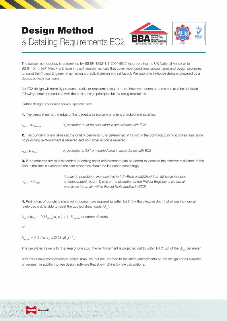
Design Method & Detailing Requirements EC2
The design methodology is determined by BS EN 1992-1-1-2004 (EC2) incorporating the UK National Annex or to BS 8110-1:1997. Max Frank have in-depth design manuals that cover most conditions encountered and design programs to assist the Project Engineer in achieving a practical design and rail layout. We also offer in-house designs prepared by a dedicated technical team.
An EC2 design will normally produce a radial or cruciform layout pattern, however square patterns can also be achieved following certain procedures with the basic design principles below being maintained.
Outline design procedures for a suspended slab:
1. The direct shear at the edge of the loaded area (column or pile) is checked and satisfied.
vEd 0 ≤ vRd.max uo perimeter must be calculated in accordance with EC2
2. The punching shear stress at the control perimeter u1 is determined; if it’s within the concrete punching stress resistance no punching reinforcement is required and no further action is required.
vEd 1 ≤ vRd.c u1 perimeter is 2d from loaded area in accordance with EC2
3. If the concrete stress is exceeded, punching shear reinforcement can be added to increase the effective resistance of the slab. If the limit is exceeded the slab properties should be increased accordingly.
vEd 1 > 2vRd.c
4. Perimeters of punching shear reinforcement are required to within kd (1.5 x the effective depth) of where the normal reinforced slab is able to resist the applied shear loads (Uout).
Asw = ((vEd 1 - 0.75vRd.c) u1 sr ) / (1.5 fywd.ef x number of studs)
or
Asw.min = (1.5 / (sr st)) x (0.08 √(fck) / fyk)
The calculated value is for the area of one stud, the reinforcement is projected out to within kd (1.5d) of the Uout perimeter.
Max Frank have comprehensive design manuals that are updated to the latest amendments of the design codes available
on request, in addition to free design software that show full line by line calculations.
(It may be possible to increase this to 2.5 vRd.c established from full scale test plus an independent report. This is at the discretion of the Project Engineer. It is normal practise is to remain within the set limits applied in EC2)
CERTIFICATE No. 14/5112
MANAGEMENT SYSTEMSMANAGEMENT SYSTEMS
5043

t e c h n o l o g i e s f o r t h e c o n s t r u c t i o n i n d u s t r y 9
It may be possible to increase stud spacing to 3.5d behind 2d from the column face, this is at the discretion of the Project Engineer
established from independent full scale testing, however it is normal practise is to remain within the set limits applied in EC2.

Shearail®10
Design Method & Detailing Requirements BS 8110
Shearail can be designed into the slab using the same design principles as for shear links and in accordance with BS 8110 part 1.
The concrete is first checked for shear at the column face against allowable limits from the code and is then checked along a perimeter at a distance of 1.5d from the column face. If shear reinforcement is not required, then no further checks are necessary. If shear reinforcement is required then the concrete is checked along subsequent further perimeters 0.75d apart until no further shear reinforcement is necessary.
The area of reinforcement required at the first perimeter (1.5d) is then split by placing at least 40% at 0.5d from the column face and 60% at 1.25d from the column face. If subsequent areas of reinforcement are required, these are spaced at 0.75d from the last perimeter of reinforcement.
Two perimeters of studs are used for the calculation of the area required.
ConditionNo moment being
consideredMoment being
considered
Internal
Edge (bending about an axis parallel to the free edge) Edge (bending about an axis perpendicular to the free edge)
Corner
1.15Vt
1.25Vt
1.4Vt
1.25Vt
1.25Vt
1.25Vt
Vt 1+1.5Mt
Vt x( )
Vt 1.25+1.5Mt
Vt x( )
1. Design at the Column Face
a. Calculate Design Effective Shear (Veff)When calculating Veff the factors shown in the table above are applied to design shear load (Vt).Please note – When considering moments, both axes of the column should be checked and the worst case Veff used.
b. Calculate Maximum Design Shear Capacity (vmax)
This should not exceed a maximum value of 0.8√ f cu or 5 N/mm2, whichever is the lower.
2. Design at the Perimeters
a. Calculate Design Concrete Shear Stress (vc)
wherenot to be taken greater than 3
≤ 40 N/mm2
vmax =Veff
u0d
vc =0.79100As
(bvd)( ) 400
d( ) fcu
25( )1 3
1 3
1 4
1.25
fcunot less than 0.67 or less than 1 for slabs greater than 400mm deep
400
d( ) 1 4
100As
(bvd)( ) 1 3
CERTIFICATE No. 14/5112
t e c h n o l o g i e s f o r t h e c o n s t r u c t i o n i n d u s t r y 11
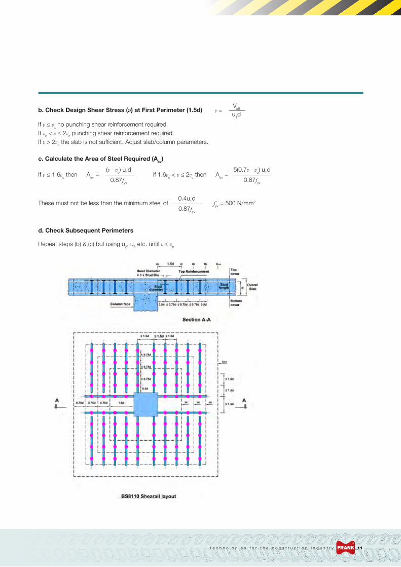
b. Check Design Shear Stress (v) at First Perimeter (1.5d)
c. Calculate the Area of Steel Required (Asv)
d. Check Subsequent Perimeters
If v ≤ vc no punching shear reinforcement required. If vc < v ≤ 2vc punching shear reinforcement required.If v > 2vc the slab is not sufficient. Adjust slab/column parameters.
If v ≤ 1.6vc then
These must not be less than the minimum steel of
Repeat steps (b) & (c) but using u2, u3 etc. until v ≤ vc
fyv = 500 N/mm2
If 1.6vc < v ≤ 2vc then
v =Veff
u1d
Asv =(v - vc) u1d
0.87fyv
0.4u1d
0.87fyv
Asv =5(0.7v - vc) u1d
0.87fyv

Shearail® link conversions
Where shear links have already been designed, they can
be quickly and easily converted and replaced by Shearail®
to comply with the original design.
The areas provided in each perimeter with Shearail® will be
at least the area provided by the links. These conversions
can be carried out either by using the link drawings or
using the output from the RCC spreadsheets.
Double headed shear studs are now a generic method,
being used fifteen years in the UK and over thirty years
in Europe.
Numerous independent tests have demonstrated the stud
heads form positive end anchorage flush with the top layer
of tension reinforcement. Whereas the anchorage of links
is based mainly on bond, the improved end anchorage of
the Shearail® stud controls the shear cracks and enhances
the aggregate interlock.
Equivalent arrangement using 24 no.
20mm diameter, 3 stud Shearail® rails.
Shearail®12
Shearail® from Max Frank is a BBA and CARES approved punching shear solution
Link conversions; EC2

Link conversions; BS 8110
Equivalent arrangement using 20 No.
14mm diameter, 4 stud Shearail® rails.
Shearail® - easy positioning and fixing
t e c h n o l o g i e s f o r t h e c o n s t r u c t i o n i n d u s t r y 13
Shearail® offers many advantages over loose
shear links which can be time consuming to
design, detail and install. Shearail® is up to
ten times faster to install and easier to check
for correct positioning.

Shearail® installation
When installing Shearail® on site, the rails can be fitted as follows:
Bottom up (recommended)
1. Rails are fitted first by spacing the rails off the formwork
using concrete spacers and nailing to the formwork
through the carrier rail and spacer.
2. The bottom and top rebars are then laid in the
usual manner around the Shearails.
Top down
1. The top and bottom rebar is fitted as per usual.
2. The rails are then placed through the rebar with the
carrier rails sitting on top of the T1. These are then
securely wire tied to the rebar so that when the concrete
is poured, they do not move.
If the rails when fitting sit on the T2 then these need
to be spaced up so they are level with the top of the T1.
Special Shearail® supports are available on request.
Installation of Shearail® in BS 8110 design
Shearail®14

t e c h n o l o g i e s f o r t h e c o n s t r u c t i o n i n d u s t r y 15
Max Frank Ltd. provide a full customer support service for Shearail®
Shearail® - fixed top down Shearail® - fixed bottom up

Max Frank provide a free design service to assist in the design and detailing of Shearail® into your project.
To benefit from Max Frank’s Shearail® design service simply email your drawings to [email protected]. Our experienced and dedicated Shearail® technical department will use their expertise to formulate the optimum concrete reinforcement strategy for your project based on the drawings and information supplied by you.
You will receive a quote prepared by our in-house costing team who will liaise with the design engineer dealing with your enquiry.
Our design service will provide full calculation sheets for your approval and can also supply DXFs for inclusion in your CAD drawings.
To enable us to proceed with a design we would require the following information:
• General Arrangement (G.A)/Layout of the floor being considered and the floor below
• Top reinforcement drawings (Bottom if transfer situation)
• Any drawings showing voids not detailed on G.A/Layouts
• Any applicable sections (steps etc.)
• Shear loads (kN) and any moments to be considered (kNm), (factors from the code will be applied if only unfactored loads are supplied)
Free design assistance
The Shearail® design software represents
a huge step forward in the design and
detailing of our leading CARES and BBA
approved prefabricated punching shear
reinforcement system.
The free of charge Shearail® Design Program enables you
to design Shearail® layouts to BS 8110 and EC2 easily and
simply. It also allows you to convert existing link designs to
an equivalent Shearail® layout.
The program provides you with fully checkable
calculations/conversions and also includes a DXF out
facility so the layouts created can easily be included in your
drawings.
The EC2 program is the first standalone program of its
kind in the UK and delivers a whole raft of new features.
Easier to use and, with a new graphical interface, it virtually
eliminates the need for a separate CAD program.
Draw voids, trim and move rails, edit layouts directly in the
program, and your calculations are automatically updated.
And instead of having to file all your calculations in a single
folder, you can now save them to the project folder of your
choice.
Advanced design& detailing
Shearail®16
Project Ref:Project Title:
Block/Building:
Floor:Column Ref:
EXAMPLEEXAMPLE
14
RoofS9
Sheet:3 of 3
REV
-
Shearail® Design Program, © Max Frank Ltd 2010, www.maxfrank.co.uk, Version 1.442
Date: 12/08/2014 (15:05)
Layout Plan
Section A-A
Shearail® requirement
175 175
286
288
286
18 rails per locationNumber of locations: 1Total number of rails: 18Rail code: ES1DDCAD5C1R
A
A
2525
300
The Shearail® Design Program enables you to design
Shearail® layouts to either BS 8110 or EC2.

Our free Shearail® design program is also available to download from our website
Data entry
Layout required
Void input
More functional for the designer
Our free of charge software enables easy and simple
design to either BS 8110 or EC2 standards. Whilst the
BS 8110 program provides for you to convert existing link
designs to an equivalent Shearail® layout, the EC2 version
delivers a number of additional benefits to designers.
Simple integration with your project file structure
• Save calculations wherever you like: a project folder,
a server or a memory stick
• Assign different locations for each calculation
Intuitive graphical interface
• Edit layouts directly in the program
- no CAD required
• Produce print out based on actual layout
- no need for additional drawings
• Dramatically simplified calculations
• Draw voids directly into the program
- no need to redraw in CAD
• Calculations are automatically updated with any
change to layout
Enhanced capabilities
• Add or remove calculations and projects quickly
and easily
t e c h n o l o g i e s f o r t h e c o n s t r u c t i o n i n d u s t r y 17
To download a copy of the program please visit
www.maxfrank.co.uk/shearail-software
Alternatively contact us via
or phone 01782 598041 to request a CD version.

Shearail® in use
The Shard, London
Bond Street Station, London
Greenwich Reach, London University Hospital of North Staffordshire, Stoke-on-Trent
Velocity Tower, Sheffield
5 Broadgate, London
Shearail®18

Shearail®
Shearail® prefabricated
punching shear reinforcement
system, CARES Approved to
EC2 and BBA Certified to
BS 8110 and EC2 for flat,
piled and post-tensioned slabs.
Egcobox®
BBA certified system for
preventing thermal bridging
between cantilevered
components i.e. balconies,
walls and the building frame.
Please note that all calculations provided are preliminary and supplied in good faith for information only. Due to the nature of the design process, the overall responsibility rests with the Project Engineer. We reserve the right to amend specifications without prior notice. Whilst the data contained in this brochure is true and accurate to the best of our knowledge at the time of publication, all liability for error and omissions, or any resulting loss or damage, however caused, is hereby excluded. © Max Frank 2014.
Max Frank on-line
Scan this QR code to
access a wealth of
information and resources
at www.maxfrank.co.uk
Egcodorn®
High-performance corrosion-
proof transverse shear force
dowel systems that can
accommodate most static
and dynamic loads.
The Reinforcement Specialists
Punching Shear Reinforcement
‘an effective solution’Punching shear failure is a catastrophic brittle type failure which occurs at the flat slab-column junction. This presentation covers the problem of slabs ‘punching’ through the column and how it can be prevented.
The seminar usually lasts 45 minutes, with a question and answer session at the end. Max Frank will be happy to cover the cost of refreshments.
The following points are covered:• Punching Shear - the problem
• Generic systems and installation
• Shearail® punching shear reinforcement
• Approvals, testing, time and cost saving
• Design to BS 8110 and EC2
• Shearail® design software
cpd seminar
• Pecafil® permanent formwork • Pecavoid® ground movement solution• MFL Void Former & Sheet Pile Infills
Also from Max Frank
• Stremaform® jointing formwork• Sealing Strips & Waterstops• Formwork Liners
Spacers
Standard and premium
spacers: single block,
bar and special spacers
manufactured from
extruded fibre-reinforced
concrete.
t e c h n o l o g i e s f o r t h e c o n s t r u c t i o n i n d u s t r y 19
Design software available
Design software available
Tubbox®
The simple fast and cost effective way to produce concrete columns on site.

Max Frank Limited Whittle Road, Meir, Stoke-on-Trent, Staffordshire ST3 7HF
Tel: +44(0)1782 598041 Fax: +44(0)1782 315056
[email protected] www.maxfrank.co.uk 1004
7/2-
GB
-10/
2014