
She Strength TW Slabs Prof Dr Salim Chapter 4: Shear ...
11
4 She Cha TW When when impo Failu trunc a). The f the to natur Crit Critic from is b o conce capita TW TW s panel critic the co ar Strength T apter 4: W Shear o n TW slabs a n slabs carry rtance. ure may occu ated cone or failure surfac op surface. T re and amoun tical sectio cal section fo the peripher . The perime entrated load als, drop pan Shear For shear force V l centerlines al shear peri olumn. TW Slabs : Shear S of Slabs are supporte concentrate ur by punchi r pyramid ar ce extends fr The angle of nt of reinforc on for TW or shear is ta ry of the sup eter b o is loc ds, or reactio nels, or shear rce V u : V u can be cal around the c imeter, unles Prof Strength ed directly by d loads, as in ing shear, w ound the col rom the bott inclination w cement. It m shear: aken perpend pport, as show cated at dista ons, or from r caps (ACI lculated as th column less ss significan f Dr Bayan Sa h of TW y columns, a n footings, s with the diago lumn, capita om of slab, a with the hori may range be dicular to the wn in fig. b. ance d/2 from changes in s 22.6.4); see he total facto the load app nt moments m alim W Slabs w as in flat slab shear near co onal crack fo al, or drop pa at the suppo izontal θ, fig etween 20 an e plane of th The perime m edges or c slab thicknes figure; ored load on plied within must be trans w/o Bea bs and flat p olumns is of ollowing the anel as show ort, diagonall g. b, depends nd 45 o . he slab and a eter of the cri corners of co ss such as ed n the area bou the area def sferred from ams lates, or critical e surface of a wn below (fig ly upward to s upon the a distance d/2 itical section olumns, dges of unded by fined by the m the slab to 1 a g. o 2 n
Transcript of She Strength TW Slabs Prof Dr Salim Chapter 4: Shear ...

4 She
Cha
TWWhenwhenimpoFailutrunca).
The fthe tonatur CritCriticfrom
is bo concecapita TW TW spanelcriticthe co
ar Strength T
apter 4:
W Shear on TW slabs an slabs carry rtance.
ure may occuated cone or
failure surfacop surface. Tre and amoun
tical sectiocal section fothe peripher
. The perime
entrated loadals, drop pan
Shear Forshear force Vl centerlines al shear periolumn.
TW Slabs
: Shear S
of Slabs are supporteconcentrate
ur by punchir pyramid ar
ce extends frThe angle of nt of reinforc
on for TW or shear is tary of the sup
eter bo is loc
ds, or reactionels, or shear
rce Vu: Vu can be cal
around the cimeter, unles
Prof
Strength
ed directly byd loads, as in
ing shear, wound the col
rom the bottinclination wcement. It m
shear: aken perpendpport, as show
cated at dista
ons, or from r caps (ACI
lculated as thcolumn less ss significan
f Dr Bayan Sa
h of TW
y columns, an footings, s
with the diagolumn, capita
om of slab, awith the hori
may range be
dicular to thewn in fig. b.
ance d/2 from
changes in s22.6.4); see
he total factothe load app
nt moments m
alim
W Slabs w
as in flat slabshear near co
onal crack foal, or drop pa
at the suppoizontal θ, fig
etween 20 an
e plane of th The perime
m edges or c
slab thicknesfigure;
ored load onplied within must be trans
w/o Bea
bs and flat polumns is of
ollowing theanel as show
ort, diagonallg. b, dependsnd 45o.
he slab and aeter of the cri
corners of co
ss such as ed
n the area bouthe area defsferred from
ams
lates, or f critical
e surface of awn below (fig
ly upward tos upon the
a distance d/2itical section
olumns,
dges of
unded by fined by the
m the slab to
1
a g.
o
2 n

4 She
Fig.
ar Strength T
: Critical
TW Slabs
section for
Prof
r TW shea
f Dr Bayan Sa
ar
alim 2

4 She
TW The Tequat
The Tthree Vc = Vc = Wher
Vc = Whe λs = s
NoteFor β
ar Strength T
Shear strTW shear strtions:
TW shear strequations:
= (1/3) [λs
= (1/12) [
re β = long λ = lightw
= (1/12) [(
re, αs = 40 = 30 = 20
size effect fa
es: β ≤ 2.0, eq. (a
TW Slabs
ength, Vc rength (stres
rength (force
s λ √f′c bo
(2 + 4 / β
side / short sweight concr
(2 + αs d
0 for interior for edge co for corner cctor
a) governs. F
Prof
ss in psi, fc’ i
e in N, fc’ in
d ]
β) λs λ √f′
side of the corete factor = =
/ bo) λs λ
column, lumn, and
column.
For an interi
f Dr Bayan Sa
in psi) shall b
MPa) shall
′c bo d ]
olumn 1.0 for norm
= 0.75 for lig
√f′c bo d ]
ior column w
alim
be the small
be the small
mal weight cghtweight co
]
(ACI 22.6
with bo / d ≤
lest of the fo
lest of the fo
(ACI 22
(ACI 2
concrete oncrete.
(ACI 2
6.5.3)
≤ 20, eq. (a)
ollowing thre
ollowing
2.6.5.2a)
22.6.5.2b)
22.6.5.2c)
governs
3
ee
)
)

4 She
Shea φVn
TW The upermSuggleg, obotto
a)Sin
ar Strength T
ar Strengt
n = Vu = φ
When V
When V
Shear strei. increasiii. increasiii. provid If shear In this c and max φ
Shear rei
use of bars, wmitted providegested rebar sor closed stirm of the slab
ngle-leg
TW Slabs
th Require
φ (Vc + Vs
Vu ≤ φ Vc
Vu > φ Vc
ength may being concrete sing slab thicding shear re
r reinforce
case, reduc
Vc
x nominal
(Vc + Vs)
nforcemen
wires, or sined that d ≥ 1shear reinforrrups that areb (ACI 8.7.6
b) mult
Prof
ements
Vs) , φ
OK, no s
N.G.
e increased bstrength fc′
ckness at coleinforcement
ement is re
ce Vc to:
c = (1/6) [
l strength:
) ≤ (1/2)
nt in slabs
gle or multip150 mm, andrcement cone engaging lo6.2); see Fig
iple-leg stirr
f Dr Bayan Sa
φ = 0.75
shear rein
by: ′ lumn support
equired:
[ λ √f′c bo
:
[ λ √f′c bo
s
ple-leg stirrud 16 db. sist of propeongitudinal r.
rup or bar
alim
nforcement
rt, i.e., using
d ]
o d ]
ups as shear
erly anchoredreinforceme
c)
(A
t is requir
g a drop pane
reinforceme
d single-leg,ent at both th
closed stirru
ACI 22.6)
red.
el
ent in slabs i
, multiple-he top and
ups
4
s

4 She
Arraa
Calc Av =Av = SpaciThe s ExamConscolumand ifOverfy = 4Live Solu
ar Strength T
angement a) Interior
culation of
= Vs s / fy cross sec areing limits arshear reinfor
mple 4-1: ider an inter
mn. Panel sizf not adequaall slab thick
420 MPa. load = 5 kN
ution:
TW Slabs
of stirrupr column
f the area
d ea of all the e shown in frcement can
rior panel of ze l1 = l2 = 6ate, increase kness h = 19
N/m2
Prof
p shear rei
of shear r
legs of shearfigs above. be terminate
f a flat plate s6.5 m. Determ
the shear str90 mm (d = 1
f Dr Bayan Sa
inforceme
reinforcem
r reinforcem
ed when Vu ≤
slab system mine shear srength by co150 mm). fc
alim
ent: b) edge
ment:
ment
≤ φ (1/6) λ √
supported bystrength of slonsidering cl′ = 28 MPa,
column
√fc′ bo d (AC
y a 300 mmlab at columlosed stirrup, normal wei
CI 22.6.6-7)
m square mn support,
s option. ight concrete
5
.
e,
Lenovo
Sticky Note
since h = 190 mm < 250 mm size factor lambda s is = 1.0 If h > 250 mm size factor should be considered.
4 She
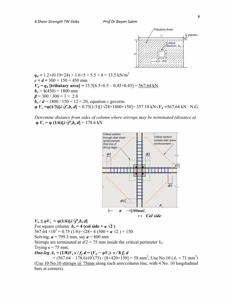
qu = c + d Vu = bo = 4β = 3bo / dφ Vc Deter φ Vc
Vu ≤ For s567.6SolviStirruTryinOne- (Use bars a
ar Strength T
1.2×(0.19×2d = 300 + 150
qu [tributar4(450) = 18000 / 300 = 1
d = 1800 / 15=φ(1/3)[λ√f
rmine distanc = φ (1/6)[λ
φVc = φ(1/6quare colum
64 ×103 = 0.7ing, a = 799.ups are terming s = 75 mm-leg Av = (1/8
= (567.10 No.10 stat corners).
TW Slabs
24) + 1.6×5 =0 = 450 mm ry area] = 100 mm < 2.0
50 = 12 < 20f′cbo d] = 0.7
nce from side√f′cbo d] = 1
6)[λ√f′cbo d]mn: bo = 4 (co75 (1/6)×√2.3 mm, say ainated at d/2
m; 8)Vs s / fy d =.64 – 178.6)irrups @ 75m
Prof
= 5.5 + 8 = 1
3.5[6.5×6.5
, equation c5(1/3)[1√28
es of column78.6 kN
|← ol side + a √8× 4 (300 + a = 800 mm2 = 75 mm in
= (Vu − φVc)103(75) / [8×mm along ea
f Dr Bayan Sa
13.5 kN/m2
– 0.45×0.45
governs. 8×1800×150]
n where stirr
← a →|
√2 ) a √2 ) × 150
nside the crit
) s / 8 fy d ×420×150] =ach arm/colu
alim
5] = 567.64 k
]= 357.18 kN
rups may be
|300mm| ↔ Col
0
tical perimet
= 58 mm2; Uumn line, wi
kN
N<Vu =567.
terminated (
side
ter bo.
Use No.10 (Aith 4 No. 10
64 kN N.G
(distance a)
Av = 71 mm2)longitudinal
6
G.
) l

4 She
EffeUnbabeamspandtransfFig.
T
fl
ɣf Mu
oppo
T
Mu = Mu =
ar Strength T
ects of Momalanced mom
ms between sudrel beam) isferred to the
The fraction olexure γf is:
u is transferrsite faces of
The fraction o
0.30 Mo (if computed f
TW Slabs
ment Tranment Mu can upports, shes especially column, wh
of unbalance
ed within anf the column
of unbalance
f DDM is useframe mome
Prof
nsfer occur at the
ear strength acritical, beca
hich is in add
ed moment t
ACI Eq
n effective wor capital. (
ed moment t
ed) ent (if EFM
f Dr Bayan Sa
slab-columnat an exteriorause the totadition to the
transferred b
q(8.4.2.2.2)
width = 1.5 hh = slab thic
transferred b
M is used)
alim
n connectionr slab-colum
al exterior nedirect shear
by
)
on each sidckness includ
by eccentricit
ACI E
Mu
tranby:
Mu
ns. For slabsmn connectioegative momr due to grav
de of columnding drop pa
ty of shear i
Eq. (8.4.4.2.2
at connectionnsferred to co
1. Flexure;2. Shear; ɣ
i,e,
= ɣf Mu + ɣv
s without on (without ment must bevity loads; se
n, outside anel if any):
s:
2)
n is olumn
; ɣf Mu ɣv Mu
v Mu
7
e ee
Lenovo
Sticky Note
This is for edge column. For interior columns, Mu = Mcol taken from ACI column equation, see Ch.3

4 She
wherto the
Shea
wherJ = parea Ac andsectio
ar Strength T
e b1 and b2 ae direction o
Critial se
ar Stress a
e: Ac = area roperty of crAc.
d c′ = distancon in the dire
TW Slabs
are the dimenf analysis; s
ection for int
and Streng
of concrete ritical sectio
ces from cenection of ana
Prof
nsions of theee Fig.
terior column
gth Consid
section resison analogous
ntroidal axis alysis.
f Dr Bayan Sa
e perimeter o
n
dering Eff
sting shear trs to polar mo
of critical se
alim
of the critica
Critial
fects of Mo
ransfer, Ac =oment of ine
ection to the
al section, w
section for e
oment Tra
= bod ertia of segm
perimeter o
ith b1 paralle
edge column
ansfer
ments forming
of the critical
8
el
n
g
l

4 She
ExpFor
ar Strength T
ressions foRectangul
TW Slabs
or Ac, c, c′lar column
Prof
′, J / c, andns;
f Dr Bayan Sa
d J / c′ ,
alim 9

4 She
ExamConssquarslab ah = 1of theVu = SoluEdgeb1 = b2 = bo = 2c = bAc = (J/c =ɣf = 1ɣv = 1Unba
= =φvc =Shear CAssumd = 1 Cvu1 ≤ be pr HW1
HW240 kN
ar Strength T
mple 4-2: ider an exterre column. Dand column 180 mm. (d ≈e slab. Consi260 kN, Mo
ution: column benc1 + d/2 = 4c2 + d = 4002 (475) + 55
b12 / (2b1 + b
(2b1 + b2) d [2b1
2d(b1 +1/[1 + (2/3)√1 - ɣf = 0.365alanced Mu =
= 260×103/22= 1.156 + 0.6= φ(1/3)√f′c =r reinforcem
Check effectiming No. 1050 mm OK
Check maximφ(1/2) √f′c =
rovided. (Oth
1: Provide cl
2: Rework ENm
TW Slabs
Shear Strrior (edge) p
Determine shsupport. Ove≈ 150 mm). ider
o = 230 kNm
nding perpen00 + 75 = 47
0 + 150 = 5550 = 1500 mmb2) = 150.4 m= 225,000 m2b2) + d3(2b
√(b1/b2)] = 0.5 = 0.3 Mo = 69
25000 + 0.3643 = 1.799 = 0.75(1/3) √
ment must be
ive depth, d 0 stirrups (db
(min 150 mmmum shear st= 0.75(1/2) √herwise, incr
losed stirrup
Ex.1 consider
Prof
rength of Spanel of a flahear strengtherall slab thiAssume tha
m, fc′ = 28 M
ndicular to ed75 mm
50 mm m
mm mm2 b1 + b2)] / 6b.635
9 kNm
65(69×106)/MPa √28 = 1.323 provided
b = 9.5 mm),m and 16 db
tress permitt√28 = 1.984rease slab th
ps as slab she
ring the effe
f Dr Bayan Sa
Slab with Tat plate slab sh for transferickness
at the Direct
MPa, fy = 42
dge (Case C
b1= 3.918×1
/3.918×107
MPa < 1.79
=150 mm) Oed with bar r MPa >1.799
hickness)
ear reinforce
cts of mome
alim
Transfer osystem supp
r of direct sh
Design Meth
20 MPa.
C),
07 mm3
99 MPa N.G
OK reinforceme9 MPa OK S
ement at edg
ent transfer.
of Momenported by a 4hear and mom
hod is used
G.
ent. Shear reinfor
ge column.
Take unbala
1
nt 400-mm ment betwee
for analysis
rcement can
anced Mu =
10
en
n

4 She
EffeThe eopeniarea. Slab lengtcentrFor sof tha
ar Strength T
ect of openeffect of opeing is locate
opening effeh equal to thoid of the colabs with shat without sh
TW Slabs
ning on sheenings in slabd within 4 h
ect is evaluathe projectionolumn and taear reinforce
hear reinforc
Prof
ear strengbs on concre
h from a colu
ted by reducn of the openangent to theement, the incement; see F
f Dr Bayan Sa
gth ete shear streumn peripher
cing the perining enclosede opening; seneffective poFig. (b).
alim
ength shall bry, a concen
imeter of thed by two-linee Fig (a). ortion of the
be consideredntrated load o
e critical secnes extending
perimeter b
1
d when the or reaction
ction bo by a g from the
bo is one-half
11
f