
SHaZam the Magic Lamp: IR-Based Gaze Tracking … the Magic Lamp: IR-Based Gaze Tracking and Light...
4
SHaZam the Magic Lamp: IR-Based Gaze Tracking and Light Direction Chaim Halbert, Dexter Scobee, and Edward Zhao EE149A/EE249A Project Final Report Fig. 1: SHaZam ConOps. This diagram represents the intercon- nections between components for the SHaZam system I. PROJECT VISION The goal of this project was to design a lamp that will redirect its light to follow a user’s gaze. The magic lamp will consist of a flashlight attached to a two-axis motor assembly, to be directed by an embedded microcontroller. Additionally, the lamp will utilize a Wiimote to track IR LEDs affixed to a specially designed hat. The Wiimote will communicate relative positioning data to the microcontroller via Bluetooth, which will in turn direct the motors to aim the flashlight. The controller will behave according to a state-machine that describes both automatic and manual modes of behvior. Figure 1 shows the logical connections between system components and how they are intended to interact, and Figure 4 depicts the governing state machines. II. HARDWARE The hardware consists of a gimbal-mounted flashlight con- nected to a system controller, in turn connected wirelessly to a Wiimote, which tracks sensor bars mounted on the user’s hat. The gimbal is a pair of Dynamixel RX-24F smart servos, which are daisy-chained and connected to the system controller via RS-485 serial link. To convert the RS-485 to 3.3V serial UART, we used an SP3485 breakout board. The system controller is a Raspberry Pi running Raspbian Linux in “headless” configuration, without a monitor, keyboard or mouse. These can be added for development and debugging, or an ethernet connection can be used to log in remotely via SSH. The system controller links to the Wiimote via a USB Bluetooth dongle. (Somehow, we had issues with newer Wiimotes that included MotionPlus, so we used an older Wiimote without it.) The WiiBrew web site 1 was a valuable resource in understanding the Wiimote hardware and in interfacing the Wiimote with the system controller. 1 http://wiibrew.org/wiki/Wiimote The hat has two Wii “sensor bars” mounted to it. These bars are not sensors at all, but actually contain a simple collection of IR LEDs at either end of each. The specially-designed camera in the Wiimote picks up and tracks these four points of invisible light. For more information about the sensor bars’ asymmetrical configuration, see section IV. Design changes Although the overall structure and linkages of our system diagram have not changed since the beginning of our project, virtually every block was modified by the end of development. 1) Gimbal: Our original design called for traditional servo motors to drive the gimbal’s motion, but we decided to change to advanced, serially-controlled servos. These Dynamixel RX-24F motors (see Figure 2) provided several advantages, the primary one being ease of control. Unlike traditional servo motors which are commanded to set their position using PWM, our smart servos could be commanded via RS-485 serial link. This provides more timing flexibility in our control logic, since this makes PWM interrupt routines unnecessary. The smart servos also allowed us to set the speed of the movements over the serial link, offloading logic from our main control loop to the motors. Also, the new servos were daisy-chainable, an impossibility with PWM. This allowed us to use a single serial output, as opposed to multiple, independent PWM outputs, each with their own interrupt routines. This resulted in a subtantial time savings in development, and greater reliability. A disadvantage was that RS-485 is quite different from serial UART, in that it uses 200 mV differential signaling over two wires and is half-duplex, whereas our TTL UART operates at 3.3V and is full-duplex. We used a breakout board for the SP3485, which accomplishes both level conversion and protocol translation, with the aid of an RTS signal from our system controller’s GPIO. 2) Bluetooth: Originally, we planned to use a BlueSMiRF Gold to connect to the Wiimote. However, the Gold only connects via serial data endpoints, while the Wiimote requires an HID interface. So, the BlueSMiRF Gold did not work. To resolve this problem, we purchased a BlueSMiRF HID, which has the same hardware as the BlueSMiRF Gold, but has different factory-flashed firmware for HID capabilities. This also did not work, because the BlueSMiRF HID was designed to operate as an HID slave device, such as a mouse, keyboard or joystick; it could not operate as an HID host, to control such HID devices. In the end, we used a USB-Bluetooth dongle. 3) System controller: Although we originally intended to use the ARM mbed FRDM-KL25Z Freedom board, we decided to change platforms to the Raspberry Pi model B.
Transcript of SHaZam the Magic Lamp: IR-Based Gaze Tracking … the Magic Lamp: IR-Based Gaze Tracking and Light...
SHaZam the Magic Lamp:IR-Based Gaze Tracking and Light Direction
Chaim Halbert, Dexter Scobee, and Edward ZhaoEE149A/EE249A Project Final Report
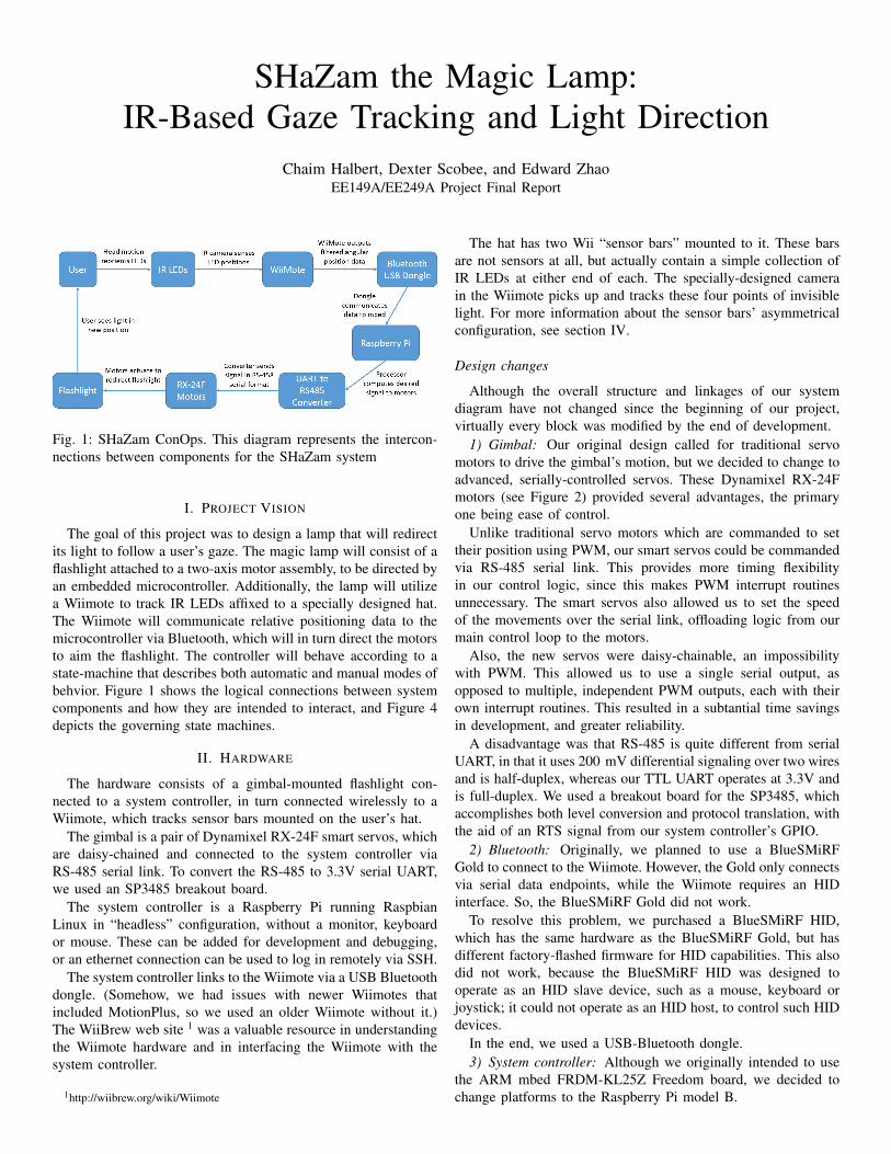
Fig. 1: SHaZam ConOps. This diagram represents the intercon-nections between components for the SHaZam system
I. PROJECT VISION
The goal of this project was to design a lamp that will redirectits light to follow a user’s gaze. The magic lamp will consist of aflashlight attached to a two-axis motor assembly, to be directed byan embedded microcontroller. Additionally, the lamp will utilizea Wiimote to track IR LEDs affixed to a specially designed hat.The Wiimote will communicate relative positioning data to themicrocontroller via Bluetooth, which will in turn direct the motorsto aim the flashlight. The controller will behave according to astate-machine that describes both automatic and manual modes ofbehvior. Figure 1 shows the logical connections between systemcomponents and how they are intended to interact, and Figure 4depicts the governing state machines.
II. HARDWARE
The hardware consists of a gimbal-mounted flashlight con-nected to a system controller, in turn connected wirelessly to aWiimote, which tracks sensor bars mounted on the user’s hat.
The gimbal is a pair of Dynamixel RX-24F smart servos, whichare daisy-chained and connected to the system controller viaRS-485 serial link. To convert the RS-485 to 3.3V serial UART,we used an SP3485 breakout board.
The system controller is a Raspberry Pi running RaspbianLinux in “headless” configuration, without a monitor, keyboardor mouse. These can be added for development and debugging,or an ethernet connection can be used to log in remotely via SSH.
The system controller links to the Wiimote via a USB Bluetoothdongle. (Somehow, we had issues with newer Wiimotes thatincluded MotionPlus, so we used an older Wiimote without it.)The WiiBrew web site 1 was a valuable resource in understandingthe Wiimote hardware and in interfacing the Wiimote with thesystem controller.
1http://wiibrew.org/wiki/Wiimote
The hat has two Wii “sensor bars” mounted to it. These barsare not sensors at all, but actually contain a simple collection ofIR LEDs at either end of each. The specially-designed camerain the Wiimote picks up and tracks these four points of invisiblelight. For more information about the sensor bars’ asymmetricalconfiguration, see section IV.
Design changes
Although the overall structure and linkages of our systemdiagram have not changed since the beginning of our project,virtually every block was modified by the end of development.
1) Gimbal: Our original design called for traditional servomotors to drive the gimbal’s motion, but we decided to change toadvanced, serially-controlled servos. These Dynamixel RX-24Fmotors (see Figure 2) provided several advantages, the primaryone being ease of control.
Unlike traditional servo motors which are commanded to settheir position using PWM, our smart servos could be commandedvia RS-485 serial link. This provides more timing flexibilityin our control logic, since this makes PWM interrupt routinesunnecessary. The smart servos also allowed us to set the speedof the movements over the serial link, offloading logic from ourmain control loop to the motors.
Also, the new servos were daisy-chainable, an impossibilitywith PWM. This allowed us to use a single serial output, asopposed to multiple, independent PWM outputs, each with theirown interrupt routines. This resulted in a subtantial time savingsin development, and greater reliability.
A disadvantage was that RS-485 is quite different from serialUART, in that it uses 200 mV differential signaling over two wiresand is half-duplex, whereas our TTL UART operates at 3.3V andis full-duplex. We used a breakout board for the SP3485, whichaccomplishes both level conversion and protocol translation, withthe aid of an RTS signal from our system controller’s GPIO.
2) Bluetooth: Originally, we planned to use a BlueSMiRFGold to connect to the Wiimote. However, the Gold only connectsvia serial data endpoints, while the Wiimote requires an HIDinterface. So, the BlueSMiRF Gold did not work.
To resolve this problem, we purchased a BlueSMiRF HID,which has the same hardware as the BlueSMiRF Gold, but hasdifferent factory-flashed firmware for HID capabilities. This alsodid not work, because the BlueSMiRF HID was designed tooperate as an HID slave device, such as a mouse, keyboard orjoystick; it could not operate as an HID host, to control such HIDdevices.
In the end, we used a USB-Bluetooth dongle.3) System controller: Although we originally intended to use
the ARM mbed FRDM-KL25Z Freedom board, we decided tochange platforms to the Raspberry Pi model B.
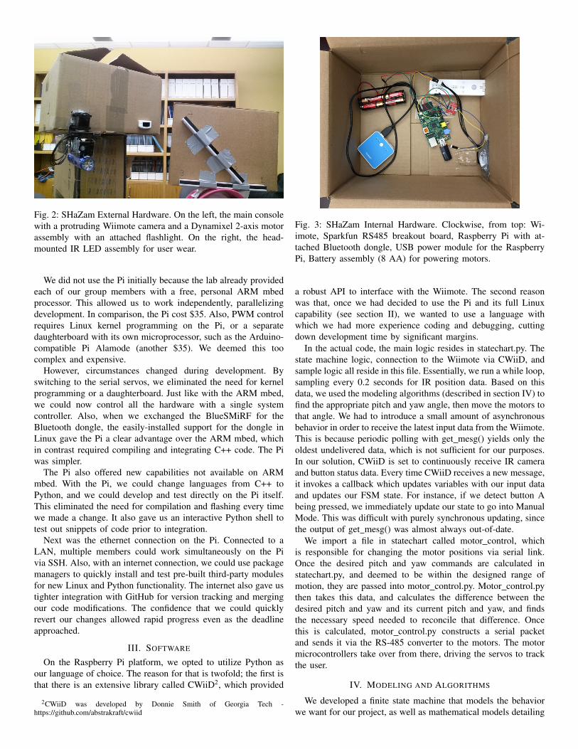
Fig. 2: SHaZam External Hardware. On the left, the main consolewith a protruding Wiimote camera and a Dynamixel 2-axis motorassembly with an attached flashlight. On the right, the head-mounted IR LED assembly for user wear.
We did not use the Pi initially because the lab already providedeach of our group members with a free, personal ARM mbedprocessor. This allowed us to work independently, parallelizingdevelopment. In comparison, the Pi cost $35. Also, PWM controlrequires Linux kernel programming on the Pi, or a separatedaughterboard with its own microprocessor, such as the Arduino-compatible Pi Alamode (another $35). We deemed this toocomplex and expensive.
However, circumstances changed during development. Byswitching to the serial servos, we eliminated the need for kernelprogramming or a daughterboard. Just like with the ARM mbed,we could now control all the hardware with a single systemcontroller. Also, when we exchanged the BlueSMiRF for theBluetooth dongle, the easily-installed support for the dongle inLinux gave the Pi a clear advantage over the ARM mbed, whichin contrast required compiling and integrating C++ code. The Piwas simpler.
The Pi also offered new capabilities not available on ARMmbed. With the Pi, we could change languages from C++ toPython, and we could develop and test directly on the Pi itself.This eliminated the need for compilation and flashing every timewe made a change. It also gave us an interactive Python shell totest out snippets of code prior to integration.
Next was the ethernet connection on the Pi. Connected to aLAN, multiple members could work simultaneously on the Pivia SSH. Also, with an internet connection, we could use packagemanagers to quickly install and test pre-built third-party modulesfor new Linux and Python functionality. The internet also gave ustighter integration with GitHub for version tracking and mergingour code modifications. The confidence that we could quicklyrevert our changes allowed rapid progress even as the deadlineapproached.
III. SOFTWARE
On the Raspberry Pi platform, we opted to utilize Python asour language of choice. The reason for that is twofold; the first isthat there is an extensive library called CWiiD2, which provided
2CWiiD was developed by Donnie Smith of Georgia Tech -https://github.com/abstrakraft/cwiid
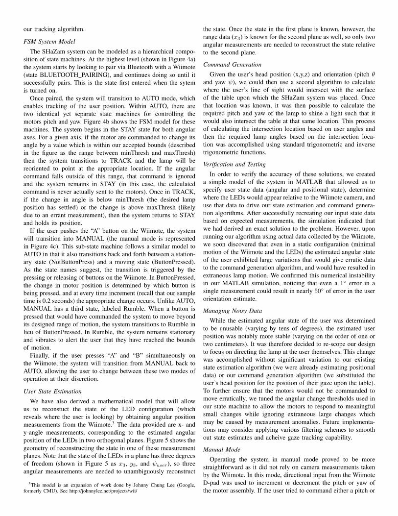
Fig. 3: SHaZam Internal Hardware. Clockwise, from top: Wi-imote, Sparkfun RS485 breakout board, Raspberry Pi with at-tached Bluetooth dongle, USB power module for the RaspberryPi, Battery assembly (8 AA) for powering motors.
a robust API to interface with the Wiimote. The second reasonwas that, once we had decided to use the Pi and its full Linuxcapability (see section II), we wanted to use a language withwhich we had more experience coding and debugging, cuttingdown development time by significant margins.
In the actual code, the main logic resides in statechart.py. Thestate machine logic, connection to the Wiimote via CWiiD, andsample logic all reside in this file. Essentially, we run a while loop,sampling every 0.2 seconds for IR position data. Based on thisdata, we used the modeling algorithms (described in section IV) tofind the appropriate pitch and yaw angle, then move the motors tothat angle. We had to introduce a small amount of asynchronousbehavior in order to receive the latest input data from the Wiimote.This is because periodic polling with get mesg() yields only theoldest undelivered data, which is not sufficient for our purposes.In our solution, CWiiD is set to continuously receive IR cameraand button status data. Every time CWiiD receives a new message,it invokes a callback which updates variables with our input dataand updates our FSM state. For instance, if we detect button Abeing pressed, we immediately update our state to go into ManualMode. This was difficult with purely synchronous updating, sincethe output of get mesg() was almost always out-of-date.
We import a file in statechart called motor control, whichis responsible for changing the motor positions via serial link.Once the desired pitch and yaw commands are calculated instatechart.py, and deemed to be within the designed range ofmotion, they are passed into motor control.py. Motor control.pythen takes this data, and calculates the difference between thedesired pitch and yaw and its current pitch and yaw, and findsthe necessary speed needed to reconcile that difference. Oncethis is calculated, motor control.py constructs a serial packetand sends it via the RS-485 converter to the motors. The motormicrocontrollers take over from there, driving the servos to trackthe user.
IV. MODELING AND ALGORITHMS
We developed a finite state machine that models the behaviorwe want for our project, as well as mathematical models detailing
our tracking algorithm.
FSM System Model
The SHaZam system can be modeled as a hierarchical compo-sition of state machines. At the highest level (shown in Figure 4a)the system starts by looking to pair via Bluetooth with a Wiimote(state BLUETOOTH PAIRING), and continues doing so until itsuccessfully pairs. This is the state first entered when the sytemis turned on.
Once paired, the system will transition to AUTO mode, whichenables tracking of the user position. Within AUTO, there aretwo identical yet separate state machines for controlling themotors pitch and yaw. Figure 4b shows the FSM model for thesemachines. The system begins in the STAY state for both angularaxes. For a given axis, if the motor are commanded to change itsangle by a value which is within our accepted bounds (describedin the figure as the range between minThresh and maxThresh)then the system transitions to TRACK and the lamp will bereoriented to point at the appropriate location. If the angularcommand falls outside of this range, that command is ignoredand the system remains in STAY (in this case, the calculatedcommand is never actually sent to the motors). Once in TRACK,if the change in angle is below minThresh (the desired lampposition has settled) or the change is above maxThresh (likelydue to an errant measurement), then the system returns to STAYand holds its position.
If the user pushes the “A” button on the Wiimote, the systemwill transition into MANUAL (the manual mode is representedin Figure 4c). This sub-state machine follows a similar model toAUTO in that it also transitions back and forth between a station-ary state (NotButtonPress) and a moving state (ButtonPressed).As the state names suggest, the transition is triggered by thepressing or releasing of buttons on the Wiimote. In ButtonPressed,the change in motor position is determined by which button isbeing pressed, and at every time increment (recall that our sampletime is 0.2 seconds) the appropriate change occurs. Unlike AUTO,MANUAL has a third state, labeled Rumble. When a button ispressed that would have commanded the system to move beyondits designed range of motion, the system transitions to Rumble inlieu of ButtonPressed. In Rumble, the system remains stationaryand vibrates to alert the user that they have reached the boundsof motion.
Finally, if the user presses “A” and “B” simultaneously onthe Wiimote, the system will transition from MANUAL back toAUTO, allowing the user to change between these two modes ofoperation at their discretion.
User State Estimation
We have also derived a mathematical model that will allowus to reconstuct the state of the LED configuration (whichreveals where the user is looking) by obtaining angular positionmeasurements from the Wiimote.3 The data provided are x- andy-angle measurements, corresponding to the estimated angularposition of the LEDs in two orthogonal planes. Figure 5 shows thegeometry of reconstructing the state in one of these measurementplanes. Note that the state of the LEDs in a plane has three degreesof freedom (shown in Figure 5 as x3, y3, and ψuser), so threeangular measurements are needed to unambiguously reconstruct
3This model is an expansion of work done by Johnny Chung Lee (Google,formerly CMU). See http://johnnylee.net/projects/wii/
the state. Once the state in the first plane is known, however, therange data (x3) is known for the second plane as well, so only twoangular measurements are needed to reconstruct the state relativeto the second plane.
Command Generation
Given the user’s head position (x,y,z) and orientation (pitch θand yaw ψ), we could then use a second algorithm to calculatewhere the user’s line of sight would intersect with the surfaceof the table upon which the SHaZam system was placed. Oncethat location was known, it was then possible to calculate therequired pitch and yaw of the lamp to shine a light such that itwould also intersect the table at that same location. This processof calculating the intersection location based on user angles andthen the required lamp angles based on the intersection loca-tion was accomplished using standard trigonometric and inversetrigonometric functions.
Verification and Testing
In order to verify the accuracy of these solutions, we createda simple model of the system in MATLAB that allowed us tospecify user state data (angular and positional state), determinewhere the LEDs would appear relative to the Wiimote camera, anduse that data to drive our state estimation and command genera-tion algorithms. After successfully recreating our input state databased on expected measurements, the simulation indicated thatwe had derived an exact solution to the problem. However, uponrunning our algorithm using actual data collected by the Wiimote,we soon discovered that even in a static configuration (minimalmotion of the Wiimote and the LEDs) the estimated angular stateof the user exhibited large variations that would give erratic datato the command generation algorithm, and would have resulted inextraneous lamp motion. We confirmed this numerical instabilityin our MATLAB simulation, noticing that even a 1◦ error in asingle measurement could result in nearly 50◦ of error in the userorientation estimate.
Managing Noisy Data
While the estimated angular state of the user was determinedto be unusable (varying by tens of degrees), the estimated userposition was notably more stable (varying on the order of one ortwo centimeters). It was therefore decided to re-scope our designto focus on directing the lamp at the user themselves. This changewas accomplished without significant variation to our existingstate estimation algorithm (we were already estimating positionaldata) or our command generation algorithm (we substituted theuser’s head position for the position of their gaze upon the table).To further ensure that the motors would not be commanded tomove erratically, we tuned the angular change thresholds used inour state machine to allow the motors to respond to meaningfulsmall changes while ignoring extraneous large changes whichmay be caused by measurement anomalies. Future implementa-tions may consider applying various filtering schemes to smoothout state estimates and acheive gaze tracking capability.
Manual Mode
Operating the system in manual mode proved to be morestraightforward as it did not rely on camera measurements takenby the Wiimote. In this mode, directional input from the WiimoteD-pad was used to increment or decrement the pitch or yaw ofthe motor assembly. If the user tried to command either a pitch or
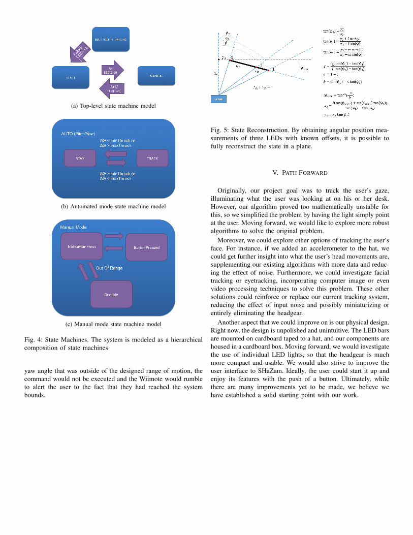
(a) Top-level state machine model
(b) Automated mode state machine model
(c) Manual mode state machine model
Fig. 4: State Machines. The system is modeled as a hierarchicalcomposition of state machines
yaw angle that was outside of the designed range of motion, thecommand would not be executed and the Wiimote would rumbleto alert the user to the fact that they had reached the systembounds.
Fig. 5: State Reconstruction. By obtaining angular position mea-surements of three LEDs with known offsets, it is possible tofully reconstruct the state in a plane.
V. PATH FORWARD
Originally, our project goal was to track the user’s gaze,illuminating what the user was looking at on his or her desk.However, our algorithm proved too mathematically unstable forthis, so we simplified the problem by having the light simply pointat the user. Moving forward, we would like to explore more robustalgorithms to solve the original problem.
Moreover, we could explore other options of tracking the user’sface. For instance, if we added an accelerometer to the hat, wecould get further insight into what the user’s head movements are,supplementing our existing algorithms with more data and reduc-ing the effect of noise. Furthermore, we could investigate facialtracking or eyetracking, incorporating computer image or evenvideo processing techniques to solve this problem. These othersolutions could reinforce or replace our current tracking system,reducing the effect of input noise and possibly miniaturizing orentirely eliminating the headgear.
Another aspect that we could improve on is our physical design.Right now, the design is unpolished and unintuitive. The LED barsare mounted on cardboard taped to a hat, and our components arehoused in a cardboard box. Moving forward, we would investigatethe use of individual LED lights, so that the headgear is muchmore compact and usable. We would also strive to improve theuser interface to SHaZam. Ideally, the user could start it up andenjoy its features with the push of a button. Ultimately, whilethere are many improvements yet to be made, we believe wehave established a solid starting point with our work.


![The satellite cursor: achieving MAGIC pointing without gaze ...ravin/papers/uist2010_satellite...non-dragging pointing tasks. Object Pointing [8]. Object pointing uses a cursor that](https://static.fdocuments.net/doc/165x107/5feec293dcf2cb31c01ce2e6/the-satellite-cursor-achieving-magic-pointing-without-gaze-ravinpapersuist2010satellite.jpg)