
Shapematchingandmodelingusingskeletalcontext - Vision...
12
Pattern Recognition 41 (2008) 1756 – 1767 www.elsevier.com/locate/pr Shape matching and modeling using skeletal context Jun Xie a , ∗ , Pheng-Ann Heng b , Mubarak Shah a a School of Electrical Engineering and Computer Science, University of Central Florida, Orlando, FL 32816, USA b Department of Computer Science and Engineering, Chinese University of Hong Kong, Shatin, Hong Kong Received 3 May 2007; accepted 5 November 2007 Abstract Shape is a significant visual clue for human perception and shape models show considerable promise as a basis for extracting objects from images. This paper proposes a novel approach for shape matching and modeling using the symmetry characterization of shape interior and the spatial relationships of shape structures. Based on the representative skeletal features, we develop a mechanism to generate a coarse segment matching between different instances of an object. Additionally, the natural correspondence of skeletal branches to sequential segments along the shape curves is employed in the matching process to avoid false correspondences across different segments. Point matches within the corresponding segments are then obtained by solving a constrained assignment problem. The validation of the proposed approach is illustrated on various data sets in the presence of considerable deformation and occlusion and the results are compared with those of popular approaches. We also demonstrate the performance of our method on biological objects for shape modeling, showing better models than those obtained by the state-of-the-art shape modeling approaches. 2007 Elsevier Ltd. All rights reserved. Keywords: Shape skeleton; Saliency structure; Shape matching; Shape modeling; Optimal matching 1. Introduction Many applications, such as anatomical modeling and shape retrieval, require an accurate dense point correspondence across a set of shapes. One way to describe a shape is to locate a finite number of points, the landmarks, on the shape curve. Landmarks are well-defined points which are supposedly homologous from one instance to the next. Compared to boundary-based methods, shape analysis using landmarks of- fers many advantages such as the convenience for shape com- parison, the ease of data storage and the possibility of applying powerful mathematical tools. In this representation, shape correspondence can be defined as a matching from the set of landmarks on one shape to that on the next, with the minimal shape difference measured using the corresponding landmarks. Although manual landmarking is an intuitive way to obtain those discernable points, it is usually labor intensive in prac- tice and studies [1] have shown that the precision of manual ∗ Corresponding author. Tel.: +1 407 8820132; fax: +1 407 2074816. E-mail address: [email protected] (J. Xie). 0031-3203/$30.00 2007 Elsevier Ltd. All rights reserved. doi:10.1016/j.patcog.2007.11.005 landmarking drifts with time and the accuracy varies among the landmarkers. This paper presents an approach to automatically establish dense matching across a set of shapes. It is a two-stage scheme involving the initial matching of shape structures and the dense point matching within corresponding curve segments. Given a set of shapes in a plane, we first extract their sym- metrical features using the medial axis transform (MAT) [2]. The benefits of applying skeleton-based methods are its natu- ral consistency with human intuition and capability to describe the local geometrical features, allowing the performance of ar- ticulated matching. Instead of pursuing the exact matching of skeletal graphs, which could introduce extra complexity and instability into the matching process, we propose to gradually match the representative samples on shape curves. Those sam- ples are determined by a local geometric scale function [3] based on the insight that the “best” set of samples is the small- est set which describes the shape uniquely. A set of context features are then generated to describe the spatial relationships among the sampling set. Before exploring the dense point matching, we develop a segment matching approach to find the coarse mapping of
Transcript of Shapematchingandmodelingusingskeletalcontext - Vision...
Pattern Recognition 41 (2008) 1756–1767www.elsevier.com/locate/pr
Shape matching and modeling using skeletal context
Jun Xiea,∗, Pheng-Ann Hengb, Mubarak Shaha
aSchool of Electrical Engineering and Computer Science, University of Central Florida, Orlando, FL 32816, USAbDepartment of Computer Science and Engineering, Chinese University of Hong Kong, Shatin, Hong Kong
Received 3 May 2007; accepted 5 November 2007
Abstract
Shape is a significant visual clue for human perception and shape models show considerable promise as a basis for extracting objects fromimages. This paper proposes a novel approach for shape matching and modeling using the symmetry characterization of shape interior and thespatial relationships of shape structures. Based on the representative skeletal features, we develop a mechanism to generate a coarse segmentmatching between different instances of an object. Additionally, the natural correspondence of skeletal branches to sequential segments alongthe shape curves is employed in the matching process to avoid false correspondences across different segments. Point matches within thecorresponding segments are then obtained by solving a constrained assignment problem. The validation of the proposed approach is illustratedon various data sets in the presence of considerable deformation and occlusion and the results are compared with those of popular approaches.We also demonstrate the performance of our method on biological objects for shape modeling, showing better models than those obtained bythe state-of-the-art shape modeling approaches.� 2007 Elsevier Ltd. All rights reserved.
Keywords: Shape skeleton; Saliency structure; Shape matching; Shape modeling; Optimal matching
1. Introduction
Many applications, such as anatomical modeling and shaperetrieval, require an accurate dense point correspondenceacross a set of shapes. One way to describe a shape is to locatea finite number of points, the landmarks, on the shape curve.Landmarks are well-defined points which are supposedlyhomologous from one instance to the next. Compared toboundary-based methods, shape analysis using landmarks of-fers many advantages such as the convenience for shape com-parison, the ease of data storage and the possibility of applyingpowerful mathematical tools. In this representation, shapecorrespondence can be defined as a matching from the set oflandmarks on one shape to that on the next, with the minimalshape difference measured using the corresponding landmarks.
Although manual landmarking is an intuitive way to obtainthose discernable points, it is usually labor intensive in prac-tice and studies [1] have shown that the precision of manual
∗ Corresponding author. Tel.: +1 407 8820132; fax: +1 407 2074816.E-mail address: [email protected] (J. Xie).
0031-3203/$30.00 � 2007 Elsevier Ltd. All rights reserved.doi:10.1016/j.patcog.2007.11.005
landmarking drifts with time and the accuracy varies among thelandmarkers. This paper presents an approach to automaticallyestablish dense matching across a set of shapes. It is a two-stagescheme involving the initial matching of shape structures andthe dense point matching within corresponding curve segments.
Given a set of shapes in a plane, we first extract their sym-metrical features using the medial axis transform (MAT) [2].The benefits of applying skeleton-based methods are its natu-ral consistency with human intuition and capability to describethe local geometrical features, allowing the performance of ar-ticulated matching. Instead of pursuing the exact matching ofskeletal graphs, which could introduce extra complexity andinstability into the matching process, we propose to graduallymatch the representative samples on shape curves. Those sam-ples are determined by a local geometric scale function [3]based on the insight that the “best” set of samples is the small-est set which describes the shape uniquely. A set of contextfeatures are then generated to describe the spatial relationshipsamong the sampling set.
Before exploring the dense point matching, we develop asegment matching approach to find the coarse mapping of
J. Xie et al. / Pattern Recognition 41 (2008) 1756–1767 1757
different structures of the shapes. This is enlightened by the factthat most parts of different instances of a specific object usu-ally have comparable outlines. The structure matching strategyallows one to explore the dense point matching within a rela-tive small space (only in corresponding parts), eliminating theerroneous matches across different structures and also offeringa significant speed-up. Dense landmark matching is finally ob-tained by minimizing the total matching cost enforced with aspatial ordering constraint.
The rest of the paper is organized as follows. Section 2 givesa brief description of previous work on shape matching usingdifferent features. In Section 3, the proposed shape matchingapproach is introduced in detail. The local feature scale func-tion is described to determine the optimal samples on the shapecurve. Based on skeleton features, we illustrate how to find thecoarse mapping of the shape structures. An effective solution isalso presented in this section to establish the dense point match-ing between the corresponding shape structures. The method isthen validated in Section 4 through the experiments on variousdatabases for shape recognition and shape modeling. Finally,our conclusions are presented in Section 5.
2. Related work
2.1. Point-based shape matching
Point-based shape matching has been studied extensively inthe literature and various approaches have been proposed tofind the sequential point correspondence from a set of shapes.A large number of these methods (e.g. Refs. [4,5]) use localgeometric features, such as curvature, angle and arc length, toidentify mathematical landmarks on the shape boundary. Oneproblem with curvature-defined landmarks is that, in some ap-plications (e.g. biological imaging), these points are not alwaysborne out clearly or uniquely by the individual shape, and inthis case the landmarks must be inferred from a more globalcontext.
Davies et al. [6] proposed to apply the minimum descriptionlength (MDL) as a quantitative measure of “simpleness” andconsidered the point correspondence problem as one of findingthe parameterization for each shape. However, like other globalshape correspondence methods [7], the MDL-based approachuses a very complicated and highly nonlinear cost function.Although some attempts using different cost functions [8] orother optimization techniques [9] have been proposed to im-prove this approach, the large optimization problem still makesit impractical for applications to large data sets.
An alternative way to describe shapes is to use arbitrary num-ber of points. Belongie et al. [10] introduced a shape match-ing scheme using roughly uniform samples. They characterizedthe property of each sample by a local descriptor, the shapecontext, and the similarity of boundary points is measuredby comparing their shape contexts. Although this approachhas produced encouraging results for a wide variety of datasets, the employed unit-length sampling technique cannot fullycapture the shape’s crucial characteristics if the sampling isnot dense enough. Another limitation of this approach is the
absence of spatial ordering constraints, leading to additional er-roneous matches. Thayananthan et al. [11] incorporated a con-tinuity constraint into the shape context matching scheme byadding a distance measure and optimized the cost function us-ing a dynamic programming method. Tu and Yuille [12] appliedthe shape context descriptor for fast shape matching. More re-cently, Ling and Jacobs [13] replace the Euclidean distance inthe shape context framework with the inner-distance to handlearticulated shapes.
2.2. Skeleton-based shape matching
The MAT is a transform of the original object which de-scribes the object completely—the union of the interiors of allmaximal disks is exactly the interior of the object. A maximaldisk is a disk contained in the shape, for which there is no otherdisk in the shape that contains it. The medial axis highlightsthe underlying structures of the overall shape, while also repre-senting important multi-scale aspects of the shape components.
Based on skeletons directly, many approaches have been de-veloped for shape matching. Liu and Geiger [14] proposed tomatch shape axis tree defined by the locus of midpoints of op-timally corresponding boundary points. However, their algo-rithm does not preserve the coherence of the shape. A variantof the medial axis, shock graph, was considered by Sharvit etal. [15] for shape recognition. Although this method leads tofairly good matches, the errors of fundamental flows can vio-late the hierarchical relations among parts of the shape. Siddiqiet al. [16] converted the shock graph to rooted trees and com-pared shapes by matching the graph trees based on subgraphisomorphism. But the choice of the oldest shock as the root ofthe tree is arbitrary and may lead to erroneous matches.
To reduce the sensitivity of traditional skeletons to the localdeformations on the shape curves, Golland and Grimson [17]proposed a skeleton approximation method in case the topologyof the skeleton is known a priori. By modeling the medialaxis with an undirected graph, they first kept the critical points(endings and junctions) unchanged and drove the graph alongthe gradient map using a snake-like algorithm. Once the graphhad been settled on the gradient ridges, the fixed points werethen adjusted via a reconstruction procedure.
Sebastian et al. [18] proposed to compare two shapes us-ing the least action path deforming one shape to another basedon the shock graph, which performs well in some shape in-dexing problems. However, finding the optimal alignment ofthe shock graph is not a trivial task. In their implementation,the deformation cost of the shock edges was found througha dynamic programming method, which resulted in a slowalgorithm.
3. Skeletal shape context (SSC)
In this paper, to detect feature points along shape curves,we describe shapes using the medial axis structures. Sincethis graph structure may change greatly due to the deforma-tion or occlusion of shape curves, we use only its character-istic points to identify the shape components and consider an
1758 J. Xie et al. / Pattern Recognition 41 (2008) 1756–1767
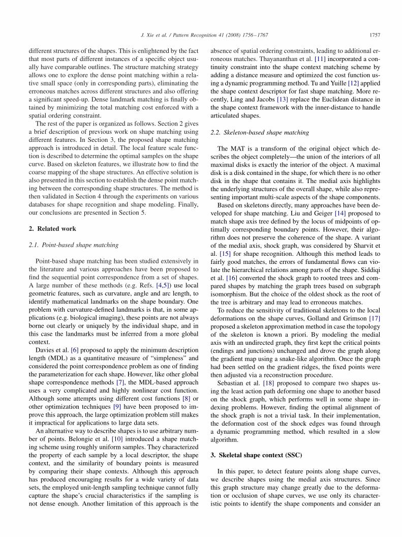
Fig. 1. An illustration of the shape sampling rule. (a) A curve (light) and its medial axis (heavy). The circle indicates a maximal disk. There are three kindsof points on the skeleton: endings, midpoints and junctions. (b) The sampling result using the �-sampling rule. There are totally 85 samples with � = 0.4 onthis curve. (c) The sampling result using curvature maxima (top 85 points).
optimal sampling approach to capture the critical characteris-tics of each shape curve. A segment matching of the curves isthen established based on the skeletal features and point cor-respondences are finally established within each pair of curvesegments.
3.1. Optimal shape sampling
Given a shape, we wish to sample the shape curve with acompact set of points, which can characterize the inherent fea-tures of the shape uniquely. In other words, this set of samplesshall lead to only one possible smoothed curve, the originalshape. This indicates a non-uniform sampling rule.
Let F(�) = (x(�), y(�)) be a smooth curve representinga shape. A point is on the medial axis of the shape if itis equidistant from two or more points on the shape curveas shown in Fig. 1(a). There are three kinds of points on askeleton: endings, midpoints and junctions. The endings andmidpoints are the skeleton points which are equidistant fromexactly two boundary points, while the junctions are equidistantfrom three or more points on the boundary. A skeleton point,which is equidistant from two boundary points, can be identi-fied as an ending if there is only one skeleton point in its eightneighbors.
An intuitive way to implement the MAT is the so-calledgrassfire transformation. There are numerous methods for me-dial axis computation (see Ref. [19] for a survey of skele-tal methods). In our approach, we apply a multi-scale method[20] to reduce the sensitivity of medial axes to image noiseand boundary details. A multi-scale representation of shapeF is achieved by computing its evolved versions as F�(�) =F(�)⊗g(�, �), where g(�, �) denotes a 1D Gaussian of width�, which is referred to as the scale parameter. In order to estab-lish a skeleton-pyramid, a sequence of scales {�1, · · · , �n} areselected to smooth the shape curve under different resolutions.This technique is suitable for removing noise from shape curveand gradually simplifying the shape.
After getting the skeleton structure W = {wz}, z = 1, . . . , Z,we can compute the local feature scale function LFS : F →R2, which is a continuous function defined as the distance ofp ∈ F to W (see Fig. 1(a) for an example). Since it is based on
medial axis, the LFS function is dominated by both the geo-metric features (e.g. curvature and orientation) and the topolog-ical features (e.g. symmetry and width). With this measure, theshape curve is sampled under the following �-sampling condi-tion. Let S ∈ R2 be a set of points on shape F. Set S is definedas a �-sample of F if, for each point p ∈ F , there is a sampleq ∈ S such that
‖p − q‖��LFS(q). (1)
Due to this sampling condition, the sample density varies withthe local feature sizes so that areas with less detail are sam-pled less densely. Fig. 1(b) shows a result of this adaptivesampling method. Compared to the curvature-based method(Fig. 1(c)), it is obvious that, using the same number of sam-ples, the LFS-based samples can describe the shape more ac-curately and comprehensively.
It is observed that, for ��1, the sample set may produce morethan one curve which is the polygonal reconstruction of thesmooth curve �-sampled by S. This indicates that the samplingis not dense enough and there may be some smaller features onthe shape that are not sampled adequately. Conversely, with aconsiderably smaller � (e.g. � < 1), the resulting samples are socompact that they can reconstruct the original curve uniquely[21,22].
One way to match two sets of such non-uniform samples isto consider all possible matchings among the points and choosethe matching with maximal similarity. However, this is compu-tationally expensive and prone to produce erroneous matches.It would be desirable to obtain a good correspondence in thefirst step. We thus propose the following two-stage matchingscheme.
3.2. Segment matching
Each structural piece of the shape leads to a correspondingbranch on the medial axis and the terminals of these branches,i.e. the endings, naturally correspond to the maxima of positivecurvature along the shape curve [23] and thus provide a goodcapability for indexing these structural portions [24]. On theother hand, it is noticed that the junctions and midpoints on
J. Xie et al. / Pattern Recognition 41 (2008) 1756–1767 1759
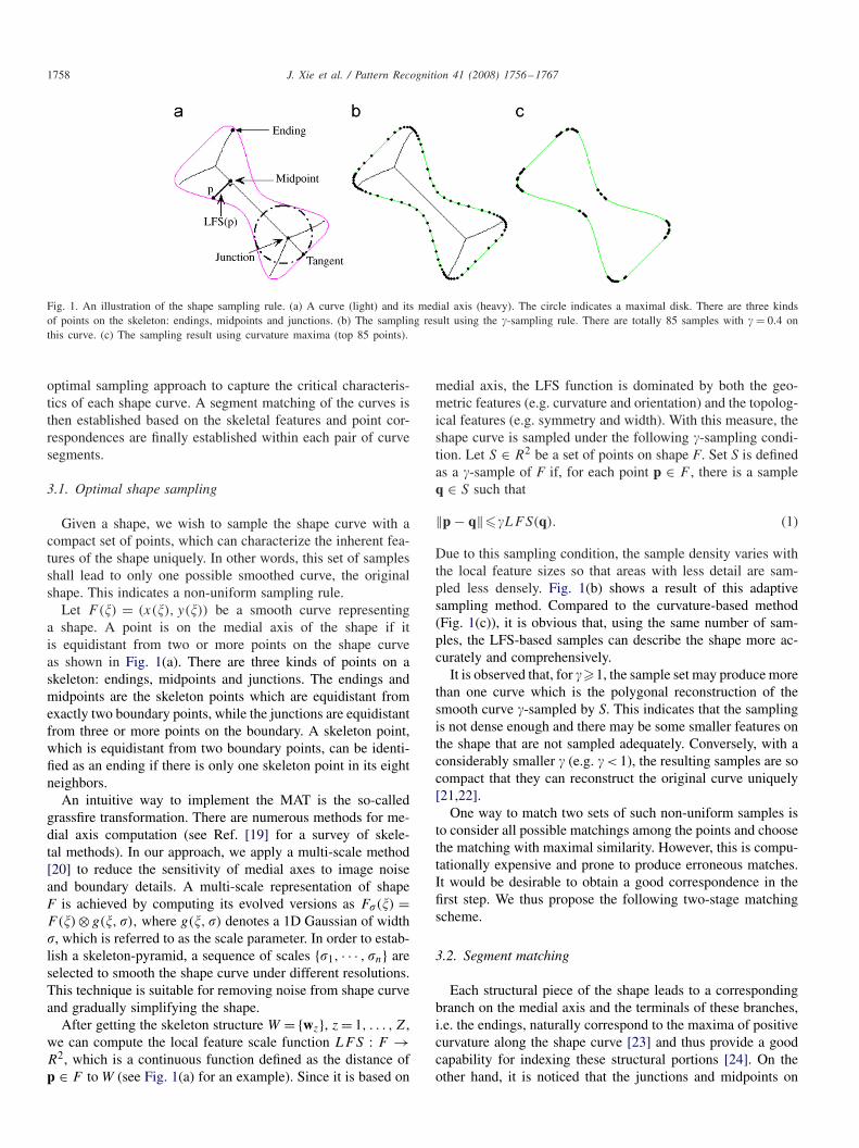
Fig. 2. Shape contexts of endings. (a) and (b) are shape outlines of two elephants. The histograms (c–f) are the computed context descriptor for four endings(A and B from (a), C, and D from (b)), respectively. It is evident that corresponding endings (e.g. endings A and C) have relatively more similar histograms.(c) For A; (d) For B; (e) For C; (f) For D.
medial axes are extremely sensitive to the changes of the shapecurves. Therefore, in this work, we use only the endings forsegment matching to avoid mismatches of the sensitive skeletalgraphs. To describe the features of these endings, we utilize thesame context descriptor as in Ref. [10].
Given a set of samples S = {si}Li=1 of a shape F and theendings E = {ek}Kk=1 on its medial axis, the context feature ofeach ek ∈ E is defined as a log-polar histogram hk:
hk(b) = #{s �= ek : (s − ek) ∈ bin(b)}, b = 1, . . . , B, (2)
where B denotes the number of bins used to describe the pointset. The resulting coarse histogram records the relative loca-tions of the sampling points referring to ek . An example of thiscontext descriptor is demonstrated in Fig. 2 where we use fivebins for distance measure log r and 12 bins for angle �. Thus,there are totally 60 bins in the log-polar space.
Using this feature, the optimal matching of two sets of end-ings can be estimated by minimizing the total matching cost∑K
1 C(ek, e�k), where �k is the index of correspondence of ek ,
and C(ek, e�k) is the difference between the context features of
ek and e�kdefined as
C(ek, e�k) = 1
2
B∑
b=1
[hk(b) − h�k(b)]2
hk(b) + h�k(b)
. (3)
If the two sets of endings have different sizes, dummy pointsmay be added to each set. The resulting square cost matrix is
then input to an assignment problem (AP), and the matchingcan be solved in O(n3) by using the Hungarian method [25]or a more efficient approach [26] based on the preflow conceptand dynamic tree data structure [27].
Now, consider a pair of corresponding endings on the twoshapes. Each ending has exactly two tangents (they collapseto one at locations with maximum positive curvature [28]).We call those tangent points ending tangent points (ETPs).Since there are only two possible mappings between the ETPsof a pair of corresponding endings, it is easy to find the cor-rect one by selecting the matching with a small matchingcost.
Fig. 3 shows an example of matching the endings betweentwo skeletons. Notice that the structures of the two skeletalgraphs are so different that, even for humans, the exact map-ping of those graphs is not straightforward. With the aid of theskeletal branches and their ETPs, however, the segment match-ing scheme provides a correct identification of the correspond-ing parts of the shapes (e.g. see the enlarged views for theendings 8 and 9 at front legs) despite the apparent deformationsand occlusions.
3.3. Point correspondence within segments
Once the segment matching is done, the global point-based shape matching problem can be converted to a se-ries of local dense matching within each pair of curvesegments. Given a pair of corresponding segments �1 =
1760 J. Xie et al. / Pattern Recognition 41 (2008) 1756–1767
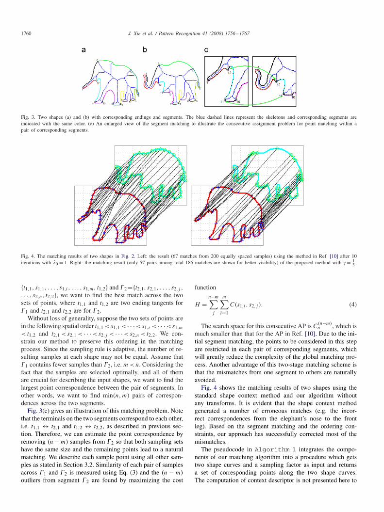
Fig. 3. Two shapes (a) and (b) with corresponding endings and segments. The blue dashed lines represent the skeletons and corresponding segments areindicated with the same color. (c) An enlarged view of the segment matching to illustrate the consecutive assignment problem for point matching within apair of corresponding segments.
Fig. 4. The matching results of two shapes in Fig. 2. Left: the result (67 matches from 200 equally spaced samples) using the method in Ref. [10] after 10iterations with �0 = 1. Right: the matching result (only 57 pairs among total 186 matches are shown for better visibility) of the proposed method with � = 1
3 .
{t1,1, s1,1, . . . , s1,i , . . . , s1,m, t1,2} and �2={t2,1, s2,1, . . . , s2,j ,
. . . , s2,n, t2,2}, we want to find the best match across the twosets of points, where t1,1 and t1,2 are two ending tangents for�1 and t2,1 and t2,2 are for �2.
Without loss of generality, suppose the two sets of points arein the following spatial order t1,1 < s1,1 < · · · < s1,i < · · · < s1,m
< t1,2 and t2,1 < s2,1 < · · · < s2,j < · · · < s2,n < t2,2. We con-strain our method to preserve this ordering in the matchingprocess. Since the sampling rule is adaptive, the number of re-sulting samples at each shape may not be equal. Assume that�1 contains fewer samples than �2, i.e. m < n. Considering thefact that the samples are selected optimally, and all of themare crucial for describing the input shapes, we want to find thelargest point correspondence between the pair of segments. Inother words, we want to find min(n, m) pairs of correspon-dences across the two segments.
Fig. 3(c) gives an illustration of this matching problem. Notethat the terminals on the two segments correspond to each other,i.e. t1,1 ↔ t2,1 and t1,2 ↔ t2,2, as described in previous sec-tion. Therefore, we can estimate the point correspondence byremoving (n − m) samples from �2 so that both sampling setshave the same size and the remaining points lead to a naturalmatching. We describe each sample point using all other sam-ples as stated in Section 3.2. Similarity of each pair of samplesacross �1 and �2 is measured using Eq. (3) and the (n − m)
outliers from segment �2 are found by maximizing the cost
function
H =n−m∑
j
m∑
i=1
C(s1,i , s2,j ). (4)
The search space for this consecutive AP is C(n−m)n , which is
much smaller than that for the AP in Ref. [10]. Due to the ini-tial segment matching, the points to be considered in this stepare restricted in each pair of corresponding segments, whichwill greatly reduce the complexity of the global matching pro-cess. Another advantage of this two-stage matching scheme isthat the mismatches from one segment to others are naturallyavoided.
Fig. 4 shows the matching results of two shapes using thestandard shape context method and our algorithm withoutany transforms. It is evident that the shape context methodgenerated a number of erroneous matches (e.g. the incor-rect correspondences from the elephant’s nose to the frontleg). Based on the segment matching and the ordering con-straints, our approach has successfully corrected most of themismatches.
The pseudocode in Algorithm 1 integrates the compo-nents of our matching algorithm into a procedure which getstwo shape curves and a sampling factor as input and returnsa set of corresponding points along the two shape curves.The computation of context descriptor is not presented here to
J. Xie et al. / Pattern Recognition 41 (2008) 1756–1767 1761
increase the readability. Since the MAT is inherently affine in-variant and the context descriptor is translation invariant (usingrelative position), scale invariant (by normalization) and robusttoward small rotations, the proposed algorithm is nearly affineinvariant.
Algorithm. 1. Skeletal shape context.
Input: shape curves Fi(pj ), i=1, 2, j =1, . . . , N , samplingfactor �Output: corresponding points across the two shapes1. InitiationFor each shape curve:Compute skeletons W = {wz}, z = 1, . . . , Z
Compute local feature size as
fs(p) = minw∈W
‖p − w‖
Sampling the curve:Pj = rj= FalseSort points pj in descending order of fs → {vj }P1 = r1= True, c = 1
while #{rj = False} > 0 dorT = True, T = {j | ‖vj − vc‖�� · fs(vc)};fs(vc) = 0;find uc: f s(uc) = maxj fs(vj ) and rc = False;Pc = rc= True
end whileSamples S = {vj |Pj = True}2. Segment matchingCompute the context descriptors hE1 and hE2
Compute cost of ending matching
C(E1, E2) = min∑
E1
∑E2
C(ex, ey)
Compute corresponding segments: �k → �k
3. Point matchFor each pair of segments
�1 = {t1,1, {s1,m}, t1,2} and �2 = {t2,1, {s2,n}, t2,2}Compute the context descriptors h�1 and h�2
Revise set s into s by removing (n − m) outliers found viamaximizing
H =n−m∑
j
m∑
i=1
C(s1,i , s2,j )
Return point matches � : {s1,m} → {s2,m}.
4. Experimental results
We have applied the algorithm to several data sets from dif-ferent domains. The performances of our algorithm for shaperecognition and retrieval are illustrated and compared withthose of popular shape recognition approaches. In addition, wedemonstrate the qualitative and quantitative results of applying
the algorithm to biomedical object shapes for shape modeling.The computation complexity and the sensitivity of our algo-rithm against the sampling condition are also demonstrated.
For each shape, we compute the medial axis using the edgemap and sample the boundary based on the local feature size.For the shape recognition and query experiments, we set � = 1
3empirically. Although we have applied the multi-scale repre-sentation of shapes to compute medial axes, the resulting skele-ton may still contain some spurious branches due to boundaryirregularity. To improve the robustness, we made use of theparametric morphological pruning transformation [29]. Givena preferred size l, a parametric pruning consists of the removalof l pixels for each skeleton branch, starting from the endings.An alternative and faster algorithm to prune the skeletons isto eliminate only the branches with length l. The size of thepruned branches can be defined as a fixed parameter or adap-tively based on the size of the skeleton, e.g. less than 3% of theskeleton length (the length of the longest branch). In the exper-iments reported here, we removed all the branches consistingof fewer pixels than l.
The resulting skeletons are then used to generate a piece-wise matching of the shape curves. This step also capturesthe hierarchical relationship between the corresponding seg-ments. To handle viewpoint changes, we measure the similarityof skeleton endings under three states: unchanged pose, ver-tically flipped pose and horizontally flipped pose. The initialmapping of the endings is decided under the pose with theminimal matching cost. Finally, the samples within the corre-sponding segments are optimally assigned with the minimalsum of matching cost.
Shape recognition: We first applied the algorithm to a smallset of shapes [15] consisting of 25 shapes of six classes(Fig. 5). In the experiment, each shape in the data set wasmatched to all others and a measure of difference was recorded.The difference between shapes F1 and F2 is defined to be theoverall cost of the optimal assignment, i.e.
D(F1, F2) = 1
M
M∑
j=1
C(s1j , s2�j), (5)
where M denotes the number of correspondences establishedacross the two shapes. For each shape, the top three most sim-ilar shapes were identified. The performance was evaluated bycounting the number of first, second and third nearest neigh-bors that fall into the correct class.
Our results for this data set are ( 2525 , 25
25 , 2425 ) while the ap-
proach in Ref. [10] reported ( 2525 , 24
25 , 2225 ) by using 100 sam-
ples. Our method gets only one erroneous match (15 → 10)
in the top three ranked matches and corrects three mismatchesof the shape context method: 8 → 4, 7 → 4 and 4 → 8. Thesame experiment was also performed by Sharvit et al. [15] andGdalyahu et al. [4] and their reported results are ( 23
25 , 2125 , 20
25 )
and ( 2525 , 21
25 , 1925 ), respectively.
Shape query: A larger data set [18] tested in our experimentsis constructed from the shape database created for testing thecompression rates for MPEG7. This data set consists of 216
1762 J. Xie et al. / Pattern Recognition 41 (2008) 1756–1767
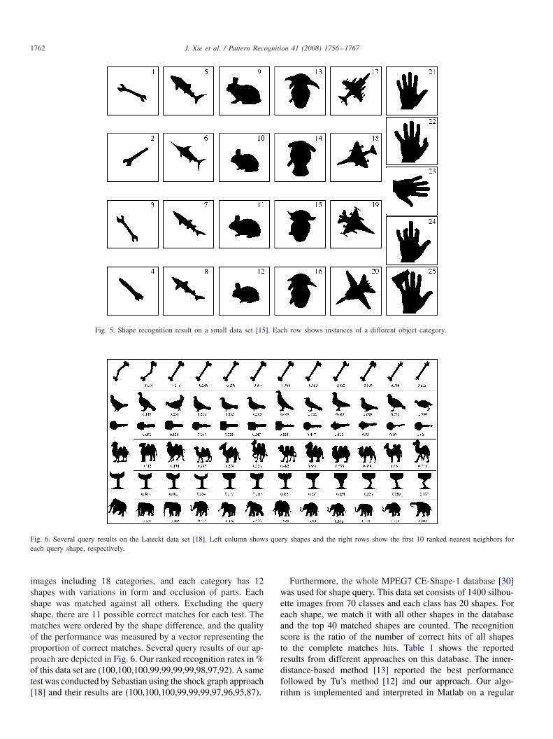
Fig. 5. Shape recognition result on a small data set [15]. Each row shows instances of a different object category.
Fig. 6. Several query results on the Latecki data set [18]. Left column shows query shapes and the right rows show the first 10 ranked nearest neighbors foreach query shape, respectively.
images including 18 categories, and each category has 12shapes with variations in form and occlusion of parts. Eachshape was matched against all others. Excluding the queryshape, there are 11 possible correct matches for each test. Thematches were ordered by the shape difference, and the qualityof the performance was measured by a vector representing theproportion of correct matches. Several query results of our ap-proach are depicted in Fig. 6. Our ranked recognition rates in %of this data set are (100,100,100,99,99,99,99,98,97,92). A sametest was conducted by Sebastian using the shock graph approach[18] and their results are (100,100,100,99,99,99,97,96,95,87).
Furthermore, the whole MPEG7 CE-Shape-1 database [30]was used for shape query. This data set consists of 1400 silhou-ette images from 70 classes and each class has 20 shapes. Foreach shape, we match it with all other shapes in the databaseand the top 40 matched shapes are counted. The recognitionscore is the ratio of the number of correct hits of all shapesto the complete matches hits. Table 1 shows the reportedresults from different approaches on this database. The inner-distance-based method [13] reported the best performancefollowed by Tu’s method [12] and our approach. Our algo-rithm is implemented and interpreted in Matlab on a regular
J. Xie et al. / Pattern Recognition 41 (2008) 1756–1767 1763
Pentium IV, 1.5 GHz PC. A single pairwise match with � = 13 ,
including the MAT, optimal sampling, mapping of skeletonendings and point matching in the segments, takes 80 ms onaverage. Due to the two-step matching strategy, our algorithmis much faster than the shape context algorithm and those us-ing statistical optimization approaches. For example, with 100landmarks, the shape context algorithm takes about 1.2 s fora single comparison of two shapes and Ling and Jacobs [13]reports 0.31 s on a 2.8 GB PC.
Another database used in our experiments is a leaf data setconstructed from the plant species database collected by theSmithsonian Institution [32] that consists of the largest, veri-fied plant-type specimen database in the world. The databasecontains 912 leaf images from 38 different species. For eachspecies, there are 24 instances with different orientations, de-formations and outlines. Fig. 7 shows some silhouettes of thoseleaves. For each image, five distance bins and 12 orienta-tion bins are used for both SC and SSC. We sampled each
Table 1Retrieval rates of different approaches for the MPEG7 database
Algorithm Visual parts [30] SC + TPS [10] Curve edit [31]
Score % 76.45 76.51 78.17
Algorithm Gen. model [12] IDSC + DP[13] SSCScore% 80.03 85.40 79.92
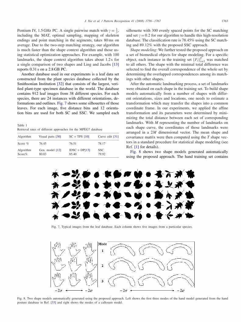
Fig. 7. Typical images from the leaf database. Each column shows five images from a particular species.
Fig. 8. Two shape models automatically generated using the proposed approach. Left shows the first three modes of the hand model generated from the handposture database in Ref. [33] and right shows the modes of a callosum model.
silhouette with 300 evenly spaced points for the SC matchingand set �= 0.2 for our algorithm to handle this high-resolutiondatabase. The classification rate is 78.45% using the SC match-ing and 89.12% with the proposed SSC approach.
Shape modeling: We further tested the proposed approach ona set of biomedical objects for shape modeling. For a specificobject, each instance in the training set {Fi}Ti=1 was matchedto all others. The shape with the minimal total difference wasselected to find the overall correspondence of the whole set bydetermining the overlapped correspondences among its match-ings with other shapes.
After the automatic landmarking process, a set of landmarkswere obtained on each shape in the training set. To build shapemodels automatically from a number of shapes with differ-ent orientations, sizes and locations, one needs to estimate atransformation which may transfer the shapes into a commoncoordinate frame. In our experiments, we applied the affinetransformation and its parameters were determined by mini-mizing the total distance between each set of correspondinglandmarks. With M representing the number of landmarks oneach shape curve, the coordinates of those landmarks werearranged in a 2M dimensional vector. The mean shape andcovariance matrix were then computed using the T shape vec-tors in a standard procedure for statistical shape modeling (seeRef. [1] for details).
Fig. 8 shows two shape models generated automaticallyusing the proposed approach. The hand training set contains

1764 J. Xie et al. / Pattern Recognition 41 (2008) 1756–1767
Table 2Evaluation of the three kidney models
Kidney model Number of points Variance
Mode 1 Mode 2 Mode 3 Total
Automatic landmarking 81 46.89 34.92 13.08 94.89Manual landmarking 54 60.13 34.91 14.58 109.62Evenly-spaced sampling 81 172.86 35.44 30.82 239.12
Fig. 9. Three kidney models generated using the proposed method, manual landmarks and evenly spaced samples.
15 hand outlines extracted from the Jochen Triesch statichand posture database [33] and the callosum set contains 14callosum shapes extracted from MRI brain slices. Using theproposed automatic landmarking algorithm, we obtained 128landmarks on each shape for the hand data set and 112 for thecallosum data set. The three rows for each modeling approachillustrate that the first three modes of the shape models variedby ±2, where denotes the standard deviation along the prin-cipal directions. As seen, compared with the manual models,our approach can generate much better automatic results thanthe even-space samples-based method.
To evaluate the effectiveness of our approach for shapemodeling, we compared the models generated using differentmethods in terms of variance of the three largest modes ofthe models. The training data consist of 20 2D left kidneyshapes from different patients. The recorded quantitative re-sults (Table 2) show that our model has the smallest variancesin all three principal directions, indicating a more compactstatistical shape model, compared with methods using manuallandmarking and even-space sampling (Fig. 9).
Finally, we performed leave-one-out tests on the callosumdata set to access the generalization capability of the proposedapproach. Given a set of the callosum outlines, a model � ={um}Mm=1 was built from all but one. We then fitted the model tothe example missed out F={pj }Nj=1 and recorded the mean ofthe distances between each point um ∈ � and its closest pointin F:
MPD(�,F) = 1
M
∑
um∈�
minpj ∈F
‖um − pj‖. (6)
The mean and deviation of pixel distance measure the gen-eralization capability of a model to represent unseen shapeinstances of the object.
Fig. 10. The results of the leave-one-out experiment on each model of thecallosum data set. The plot shows the mean pixel distances against the numberof modes used for shape fit test. The error bars indicate the standard deviationof the pixel distances of each model to the test shape.
We repeated this procedure by missing out each of the exam-ples in turn. The performances of four models generated usingdifferent methods are shown in Fig. 10. As seen from the plots,for any number of modes used to fit the unseen shape, the pro-posed algorithm could obtain a comparable result with that us-ing manual landmarks and performed considerably better thanboth the MDL approach and evenly spaced landmarks-basedmethod.
The performances of our algorithm with different settings ofthe sampling factor are illustrated in Fig. 11 including the sizeof the resulting correspondences (NC) across the training setand the pixel distances measured using five modes. It is clearthat a small sampling factor can lead to a good result due to

J. Xie et al. / Pattern Recognition 41 (2008) 1756–1767 1765
Fig. 11. The overall number of correspondences and the mean pixel distance using five modes for the callosum data set against the value of sampling parameter �.
Fig. 12. The computational time for the leave-one-out experiment againstdifferent sampling factors.
the large set of correspondences. However, increasing the sizeof samples would introduce more computational complexityin the matching algorithm as demonstrated in Fig. 12 whichshows the computational time of our algorithm for the leave-one-out tests on the callosum data set with different valuesof �. This indicates that parameter � should be chosen smallenough to capture the crucial characteristic of shapes (withconsiderable dense of landmarks), but not too small such thatthe shape matching process becomes too complex. For the sametraining data, another automatic modeling algorithm, the MDLapproach, took about 1 h using four levels of refinement.
5. Conclusions and discussions
In this paper, we have proposed and illustrated a method fordetermining point correspondences among different shapes.
Instead of using uniform samples as in Refs. [10,13], wedescribe a shape curve using a set of optimal samples extractedusing both geometric and topological features to capture thecrucial characteristic of the shape. Then the shape correspon-dence is obtained through a two-stage matching approach,which stands for the major contribution of this paper. Thecoarse mapping of the skeleton endings provides an initialmapping of the major parts of the shapes, yet allows the follow-ing local point matching so that the computational complexitycan be significantly reduced. Meanwhile, the consecutive en-forcement employed in the point matching process enables theproposed approach to avoid the mismatching raised in otherlandmark-based methods (e.g. Ref. [10]).
Compared with some methods which require the pre-cise matching of the skeleton structures (e.g. Ref. [18]), ourapproach is more flexible and efficient. The introduced coarse-to-fine matching strategy enables it to handle occlusions anddeformations naturally. The shape retrieval experiments showthe validity of the proposed shape matching approach. Theinherent flexibility of our technique makes it possible to estab-lish correspondences in variable density, which is a particularadmirable feature in applications where the information ofa large number of objects is available in various levels. Thequantitative results for shape modeling illustrate that the pro-posed method may generate better models than the traditionalapproaches and obtain comparable outputs with the MDLalgorithm [6] at a considerably lower computational cost.
To further improve the robustness of our approach for com-plex shapes, the initial segment matching may be pursuedin a multi-scale manner. The generality of this approach totasks on larger data sets with complex background will alsobe explored in the future. The presented algorithm considersonly objects represented by closed boundaries. The exten-sion of this approach to open curves is straightforward byconnecting the end-points with a straight line. However, it
1766 J. Xie et al. / Pattern Recognition 41 (2008) 1756–1767
is difficult for our approach to handle self-occluding bound-aries due to the challenges of finding the accurate symmetrystructures and the complex topology embedded in the result-ing graphs. Addressing this problem is done in our currentwork, together with extending the correspondence algorithm tovoxellated surfaces in 3D with a medial surfaces computationtechnique.
References
[1] T. Cootes, C. Beeston, G. Edwards, C. Taylor, A unified frameworkfor atlas matching using active appearance models, in: Proceedings ofthe International Conference on Image Processing in Medical Imaging,Springer, Berlin, 1999, pp. 322–333.
[2] H. Blum, A transformation for extracting new descriptors of shape, in:Proceedings of the Models for the Perception of Speech and VisualForm, Cambridge, MA, 1967, pp. 362–380.
[3] J. Ruppert, A new and simple algorithm for quality 2-dimensional meshgeneration, in: Proceedings of the ACM–SIAM Symposium on Discretealgorithms, 1993, pp. 83–92.
[4] Y. Gdalyahu, D. Weinshall, Flexible syntactic matching of curves and itsapplication to automatic hierarchical classification of silhouettes, IEEETrans. Pattern Anal. Mach. Intell. 21 (12) (1999) 1312–1328.
[5] E.G.M. Petrakis, A. Diplaros, E. Milios, Matching and retrieval ofdistorted and occluded shapes using dynamic programming, IEEE Trans.Pattern Anal. Mach. Intell. 24 (11) (2002) 1501–1516.
[6] R. Davies, C. Twining, T. Cootes, J. Waterton, C. Taylor, A minimumdescription length approach to statistical shape modeling, IEEE Trans.Med. Imag. 21 (5) (2002) 525–537.
[7] A. Hill, C. Taylor, A. Brett, A framework for automatic landmarkidentification using a new method of nonrigid correspondence, IEEETrans. Pattern Anal. Mach. Intell. 22 (3) (2000) 241–251.
[8] H. H. Thodberg, H. Olafsdottir, Adding curvature to minimumdescription length shape models, in: Proceedings of the British MachineVision Conference, vol. 2, 2003, pp. 251–260.
[9] A. Ericsson, K. Astrom, Minimizing the description length using steepestdescent, in: Proceedings of the British Machine Vision Conference, vol.2, Norwich, UK, 2003, pp. 93–102.
[10] S. Belongie, J. Malik, J. Puzicha, Shape matching and object recognitionusing shape contexts, IEEE Trans. Pattern Anal. Mach. Intell. 24 (2002)509–522.
[11] A. Thayananthan, B. Stenger, P.H.S. Torr, R. Cipolla, Shape contextand chamfer matching in cluttered scenes, in: Proceedings of the IEEEComputer Vision and Pattern Recognition, vol. I, Madison, USA, 2003,pp. 127–133.
[12] Z. Tu, A.L. Yuille, Shape matching and recognition—using generativemodels and informative features, in: European Conference on ComputerVision, vol. 3, 2004, pp. 195–209.
[13] H. Ling, D.W. Jacobs, Using the inner-distance for classification ofarticulated shapes, in: IEEE Computer Society Conference on ComputerVision and Pattern Recognition (CVPR), vol. 2, 2005, pp. 719–726.
[14] T.-L. Liu, D. Geiger, Approximate tree matching and shape similarity, in:Proceedings of the IEEE International Conference on Computer Vision,Corfu, Greece, 1999, pp. 456–462.
[15] D. Sharvit, J. Chan, H. Tek, B.B. Kimia, Symmetry-based indexing ofimage databases, J. Visual Commun. Image Representation 9 (4) (1998)366–380.
[16] K. Siddiqi, S. Bouix, A. Tannenbaum, S.W. Zucker, The Hamilton–Jacobiskeleton, in: Proceedings of the IEEE International Conference onComputer Vision, Corfu, Greece, 1999, pp. 828–834.
[17] P. Golland, W. Grimson, Fixed topology skeletons, in: Proceedings ofthe IEEE Computer Vision and Pattern Recognition, vol. I, Hilton HeadIsland, SC, 2001, pp. 10–17.
[18] T.B. Sebastian, P.N. Klein, B.B. Kimia, Recognition of shapes by editingtheir shock graphs, IEEE Trans. Pattern Anal. Mach. Intell. 26 (5) (2004)550–571.
[19] S.M. Pizer, K. Siddiqi, G. Szekely, J.N. Damon, S.W. Zucker, Multiscalemedial loci and their properties, Int. J. Comput. Vision 55 (2–3) (2003)155–179.
[20] R.L. Ogniewicz, Skeleton-space: a multiscale shape descriptioncombining region and boundary information, in: Proceedings of the IEEEComputer Vision and Pattern Recognition, 1994, pp. 746–751.
[21] N. Amenta, M. Bern, M. Kamvysselis, A new Voronoi basedsurface reconstruction algorithm, in: Computer Graphics (SIGGRAPH’98Proceedings), vol. 32, 1998, pp. 415–421.
[22] T. Dey, J. Giesen, S. Goswami, J. Hudson, R. Wenger, W. Zhao,Undersampling and oversampling in sample based shape modeling, in:Proceedings of the IEEE Visualization, vol. I, San Diego, CA, 2001, pp.83–90.
[23] F. Leymarie, M.D. Levine, Simulating the grassfire transform using anactive contour model, IEEE Trans. Pattern Anal. Mach. Intell. 14 (1)(1992) 56–75.
[24] R. Kimmel, D. Shaked, N. Kiryati, Skeletonization via distance mapsand level sets, Comput. Vision Image Understanding 62 (3) (1995)382–391.
[25] C.H. Papadimitriou, et al., Combinatorial Optimization: Algorithms andComplexity, Prentice-Hall, Englewood Cliffs, NJ, 1982.
[26] A. Goldberg, et al., A new approach to the maximum flow problem,J. Assoc. Comput. Mach. 35 (1988) 921–940.
[27] D.D. Sleator, R.E. Tarjan, A data structure for dynamic trees, J. Comput.Syst. Sci. 26 (3) (1983) 362–391.
[28] M. Leyton, Symmetry-curvature duality, Comput. Vision Graph. ImageProcess. 38 (3) (1987) 327–341.
[29] P. Soille, Morphological Image Analysis—Principles and Applications,Springer, Berlin, New York, 2004.
[30] L.J. Latecki, R. Lakamper, U. Eckhardt, Shape descriptors for non-rigid shapes with a single closed contour, in: Proceedings of theIEEE Computer Vision and Pattern Recognition, Madison, USA, 2000,pp. 424–429.
[31] T.B. Sebastian, P.N. Klein, B.B. Kimia, On aligning curves, IEEE Trans.Pattern Anal. Mach. Intell. 25 (1) (2003) 116–125.
[32] Electronic field guide, 〈http://herbarium.cs.columbia.edu/index.php〉.[33] J. Triesch, C. Malsburg, A system for person-independent hand posture
recognition against complex backgrounds, IEEE Trans. Pattern Anal.Mach. Intell. 23 (12) (2001) 1449–1453.
About the Author—JUN XIE received the M.S.E degree in computer science from the Nanjing University of Science and Technology, Nanjing, China, in2001, and the Ph.D. degree in electronic engineering from Chinese University of Hong Kong, Shatin, in 2004. During 2005, he worked as a PostdoctoralFellow in the Department of Computer Science and Engineering, the Chinese University of Hong Kong. At present, he is a Research Associate at the VisionLab of University of Central Florida. His current research focuses on ultrasound image segmentation, deformable shape modeling and human perception.
About the Author—PHEN-GANN HENG (S’90–M’92) received the B.Sc. degree from the National University of Singapore, Singapore, in 1985, and theM.Sc. degree in computer science, the M.A. degree in applied mathematics and the Ph.D. degree in computer science, all from Indiana University, Bloomington,in 1987, 1988 and 1992, respectively. Currently, he is a Professor in the Department of Computer Science and Engineering, the Chinese University of HongKong (CUHK), Shatin. In 1999, he set up the Virtual Reality, Visualization and Imaging Research Centre at CUHK and serves as the Director of the centre. Heis also the Director of the CUHK Strategic Research Area in Computer Assisted Medicine, established jointly by the Faculty of Engineering and the Facultyof Medicine in 2000. His research interests include virtual reality applications in medicine, visualization, 3D medical imaging, user interface, rendering andmodeling and interactive graphics and animation.

J. Xie et al. / Pattern Recognition 41 (2008) 1756–1767 1767
About the Author—MUBARAK SHAH is a Professor of computer science, and the Founding Director of the Computer Vision Laboratory at Universityof Central Florida (UCF). He is a co-author of two books “Video Registration” (2003) and “Motion-Based Recognition” (1997), both by Kluwer AcademicPublishers. He has published close to 150 papers in leading journals and conferences on topics including activity and gesture recognition, violence detection, eventontology, object tracking (fixed camera, moving camera, multiple overlapping and non-overlapping cameras), video segmentation, story and scene segmentation,view morphing, ATR, wide-baseline matching and video registration. He is a Fellow of IEEE and was an IEEE Distinguished Visitor Speaker for 1997–2000.He received the Harris Corporation Engineering Achievement Award in 1999, the TOKTEN Awards from UNDP in 1995, 1997 and 2000, Research IncentiveAward in 2003 and IEEE Outstanding Engineering Educator Award in 1997. He is an Editor of international book series on “Video Computing”, Editor in Chiefof Machine Vision and Applications journal and an Associate Editor of Pattern Recognition journal. He was an Associate Editor of the IEEE Transactions onPattern Analysis and Machine Intelligence and a Guest Editor of the special issue of International Journal of Computer Vision on Video Computing.


