SFP+ Tunable Preliminary - Eoptolink€¦ · SFP+ Tunable Preliminary Eoptolink Technology Inc.,...
12
SFP+ Tunable Preliminary Eoptolink Technology Inc., Ltd. V1.e Page 1 of 12 EOLP-1696-TDW-23XXXN MSA Series SFP+ Single-Mode Tunable Transceiver RoHS6 Compliant Ordering Information Part No. Data Rate Laser Power budget CDR Temp. EOLP-1696-TDW-23XXXN *(note1) 0.614 to 11.3Gbps ILMZ 23dB No Standard Note1: XXX refers to DWDM Wavelength channel as ITU-T specified. Features Support data rate 0.614 to 11.3Gbps 1550 nm ITU-T C-band 50 GHz spacing Tunable DWDM SFP+ Transceiver Temperature-Stabilized DWDM EML Transmitter Negative chirp transmitter with ILMZ (Integrated Laser Mach Zehnder) TOSA APD receiver with limiting amplifier Low power consumption: <1.8 W at 70°C Positive power supply lines: 3.3 V Hot-Pluggable SFP+ Footprint Compliant with SFF-8431 MSA Compliant with SFF-8432 MSA Operating Case Temperature Standard: 0°C to 70°C Applications 10GBASE-ZR/ZW 10G FC CPRI rates 9.830 Gb/s,7.373Gb/s, 6.144 Gb/s, 4.915 Gb/s, 2.458 Gb/s, 1.229 Gb/s, 0.614Gb/s Other optical links
Transcript of SFP+ Tunable Preliminary - Eoptolink€¦ · SFP+ Tunable Preliminary Eoptolink Technology Inc.,...
SFP+ Tunable Preliminary
Eoptolink Technology Inc., Ltd. V1.e Page 1 of 12
EOLP-1696-TDW-23XXXN MSA Series
SFP+ Single-Mode Tunable Transceiver
RoHS6 Compliant
Ordering Information
Part No. Data Rate Laser Power
budget CDR Temp.
EOLP-1696-TDW-23XXXN *(note1) 0.614 to
11.3Gbps ILMZ 23dB No Standard
Note1: XXX refers to DWDM Wavelength channel as ITU-T specified.
Features
Support data rate 0.614 to 11.3Gbps
1550 nm ITU-T C-band 50 GHz spacing Tunable
DWDM SFP+ Transceiver Temperature-Stabilized
DWDM EML Transmitter
Negative chirp transmitter with ILMZ (Integrated
Laser Mach Zehnder) TOSA
APD receiver with limiting amplifier
Low power consumption: <1.8 W at 70°C
Positive power supply lines: 3.3 V
Hot-Pluggable SFP+ Footprint
Compliant with SFF-8431 MSA
Compliant with SFF-8432 MSA
Operating Case Temperature
Standard: 0°C to 70°C
Applications
10GBASE-ZR/ZW
10G FC
CPRI rates 9.830 Gb/s,7.373Gb/s, 6.144
Gb/s, 4.915 Gb/s, 2.458 Gb/s, 1.229 Gb/s,
0.614Gb/s
Other optical links
SFP+ Tunable Preliminary
Eoptolink Technology Inc., Ltd. V1.e Page 2 of 12
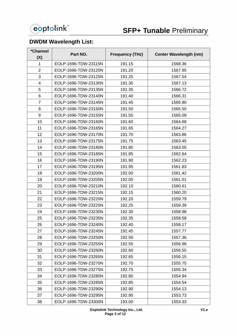
DWDM Wavelength List:
*Channel
(X) Part NO. Frequency (THz) Center Wavelength (nm)
1 EOLP-1696-TDW-23115N 191.15 1568.36
2 EOLP-1696-TDW-23120N 191.20 1567.95
3 EOLP-1696-TDW-23125N 191.25 1567.54
4 EOLP-1696-TDW-23130N 191.30 1567.13
5 EOLP-1696-TDW-23135N 191.35 1566.72
6 EOLP-1696-TDW-23140N 191.40 1566.31
7 EOLP-1696-TDW-23145N 191.45 1565.90
8 EOLP-1696-TDW-23150N 191.50 1565.50
9 EOLP-1696-TDW-23155N 191.55 1565.09
10 EOLP-1696-TDW-23160N 191.60 1564.68
11 EOLP-1696-TDW-23165N 191.65 1564.27
12 EOLP-1696-TDW-23170N 191.70 1563.86
13 EOLP-1696-TDW-23175N 191.75 1563.45
14 EOLP-1696-TDW-23180N 191.80 1563.05
15 EOLP-1696-TDW-23185N 191.85 1562.64
16 EOLP-1696-TDW-23190N 191.90 1562.23
17 EOLP-1696-TDW-23195N 191.95 1561.83
18 EOLP-1696-TDW-23200N 192.00 1561.42
19 EOLP-1696-TDW-23205N 192.05 1561.01
20 EOLP-1696-TDW-23210N 192.10 1560.61
21 EOLP-1696-TDW-23215N 192.15 1560.20
22 EOLP-1696-TDW-23220N 192.20 1559.79
23 EOLP-1696-TDW-23225N 192.25 1559.39
24 EOLP-1696-TDW-23230N 192.30 1558.98
25 EOLP-1696-TDW-23235N 192.35 1558.58
26 EOLP-1696-TDW-23240N 192.40 1558.17
27 EOLP-1696-TDW-23245N 192.45 1557.77
28 EOLP-1696-TDW-23250N 192.50 1557.36
29 EOLP-1696-TDW-23255N 192.55 1556.96
30 EOLP-1696-TDW-23260N 192.60 1556.55
31 EOLP-1696-TDW-23265N 192.65 1556.15
32 EOLP-1696-TDW-23270N 192.70 1555.75
33 EOLP-1696-TDW-23275N 192.75 1555.34
34 EOLP-1696-TDW-23280N 192.80 1554.94
35 EOLP-1696-TDW-23285N 192.85 1554.54
36 EOLP-1696-TDW-23290N 192.90 1554.13
37 EOLP-1696-TDW-23295N 192.95 1553.73
38 EOLP-1696-TDW-23300N 193.00 1553.33
SFP+ Tunable Preliminary
Eoptolink Technology Inc., Ltd. V1.e Page 3 of 12
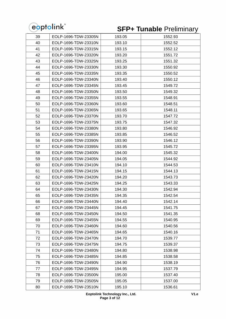
39 EOLP-1696-TDW-23305N 193.05 1552.93
40 EOLP-1696-TDW-23310N 193.10 1552.52
41 EOLP-1696-TDW-23315N 193.15 1552.12
42 EOLP-1696-TDW-23320N 193.20 1551.72
43 EOLP-1696-TDW-23325N 193.25 1551.32
44 EOLP-1696-TDW-23330N 193.30 1550.92
45 EOLP-1696-TDW-23335N 193.35 1550.52
46 EOLP-1696-TDW-23340N 193.40 1550.12
47 EOLP-1696-TDW-23345N 193.45 1549.72
48 EOLP-1696-TDW-23350N 193.50 1549.32
49 EOLP-1696-TDW-23355N 193.55 1548.91
50 EOLP-1696-TDW-23360N 193.60 1548.51
51 EOLP-1696-TDW-23365N 193.65 1548.11
52 EOLP-1696-TDW-23370N 193.70 1547.72
53 EOLP-1696-TDW-23375N 193.75 1547.32
54 EOLP-1696-TDW-23380N 193.80 1546.92
55 EOLP-1696-TDW-23385N 193.85 1546.52
56 EOLP-1696-TDW-23390N 193.90 1546.12
57 EOLP-1696-TDW-23395N 193.95 1545.72
58 EOLP-1696-TDW-23400N 194.00 1545.32
59 EOLP-1696-TDW-23405N 194.05 1544.92
60 EOLP-1696-TDW-23410N 194.10 1544.53
61 EOLP-1696-TDW-23415N 194.15 1544.13
62 EOLP-1696-TDW-23420N 194.20 1543.73
63 EOLP-1696-TDW-23425N 194.25 1543.33
64 EOLP-1696-TDW-23430N 194.30 1542.94
65 EOLP-1696-TDW-23435N 194.35 1542.54
66 EOLP-1696-TDW-23440N 194.40 1542.14
67 EOLP-1696-TDW-23445N 194.45 1541.75
68 EOLP-1696-TDW-23450N 194.50 1541.35
69 EOLP-1696-TDW-23455N 194.55 1540.95
70 EOLP-1696-TDW-23460N 194.60 1540.56
71 EOLP-1696-TDW-23465N 194.65 1540.16
72 EOLP-1696-TDW-23470N 194.70 1539.77
73 EOLP-1696-TDW-23475N 194.75 1539.37
74 EOLP-1696-TDW-23480N 194.80 1538.98
75 EOLP-1696-TDW-23485N 194.85 1538.58
76 EOLP-1696-TDW-23490N 194.90 1538.19
77 EOLP-1696-TDW-23495N 194.95 1537.79
78 EOLP-1696-TDW-23500N 195.00 1537.40
79 EOLP-1696-TDW-23505N 195.05 1537.00
80 EOLP-1696-TDW-23510N 195.10 1536.61
SFP+ Tunable Preliminary
Eoptolink Technology Inc., Ltd. V1.e Page 4 of 12
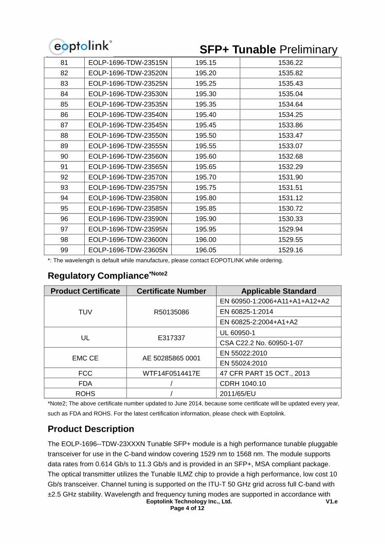
81 EOLP-1696-TDW-23515N 195.15 1536.22
82 EOLP-1696-TDW-23520N 195.20 1535.82
83 EOLP-1696-TDW-23525N 195.25 1535.43
84 EOLP-1696-TDW-23530N 195.30 1535.04
85 EOLP-1696-TDW-23535N 195.35 1534.64
86 EOLP-1696-TDW-23540N 195.40 1534.25
87 EOLP-1696-TDW-23545N 195.45 1533.86
88 EOLP-1696-TDW-23550N 195.50 1533.47
89 EOLP-1696-TDW-23555N 195.55 1533.07
90 EOLP-1696-TDW-23560N 195.60 1532.68
91 EOLP-1696-TDW-23565N 195.65 1532.29
92 EOLP-1696-TDW-23570N 195.70 1531.90
93 EOLP-1696-TDW-23575N 195.75 1531.51
94 EOLP-1696-TDW-23580N 195.80 1531.12
95 EOLP-1696-TDW-23585N 195.85 1530.72
96 EOLP-1696-TDW-23590N 195.90 1530.33
97 EOLP-1696-TDW-23595N 195.95 1529.94
98 EOLP-1696-TDW-23600N 196.00 1529.55
99 EOLP-1696-TDW-23605N 196.05 1529.16
*: The wavelength is default while manufacture, please contact EOPOTLINK while ordering.
Regulatory Compliance*Note2
Product Certificate Certificate Number Applicable Standard
TUV R50135086
EN 60950-1:2006+A11+A1+A12+A2
EN 60825-1:2014
EN 60825-2:2004+A1+A2
UL E317337 UL 60950-1
CSA C22.2 No. 60950-1-07
EMC CE AE 50285865 0001 EN 55022:2010
EN 55024:2010
FCC WTF14F0514417E 47 CFR PART 15 OCT., 2013
FDA / CDRH 1040.10
ROHS / 2011/65/EU
*Note2; The above certificate number updated to June 2014, because some certificate will be updated every year,
such as FDA and ROHS. For the latest certification information, please check with Eoptolink.
Product Description
The EOLP-1696--TDW-23XXXN Tunable SFP+ module is a high performance tunable pluggable
transceiver for use in the C-band window covering 1529 nm to 1568 nm. The module supports
data rates from 0.614 Gb/s to 11.3 Gb/s and is provided in an SFP+, MSA compliant package.
The optical transmitter utilizes the Tunable ILMZ chip to provide a high performance, low cost 10
Gb/s transceiver. Channel tuning is supported on the ITU-T 50 GHz grid across full C-band with
±2.5 GHz stability. Wavelength and frequency tuning modes are supported in accordance with
SFP+ Tunable Preliminary
Eoptolink Technology Inc., Ltd. V1.e Page 5 of 12
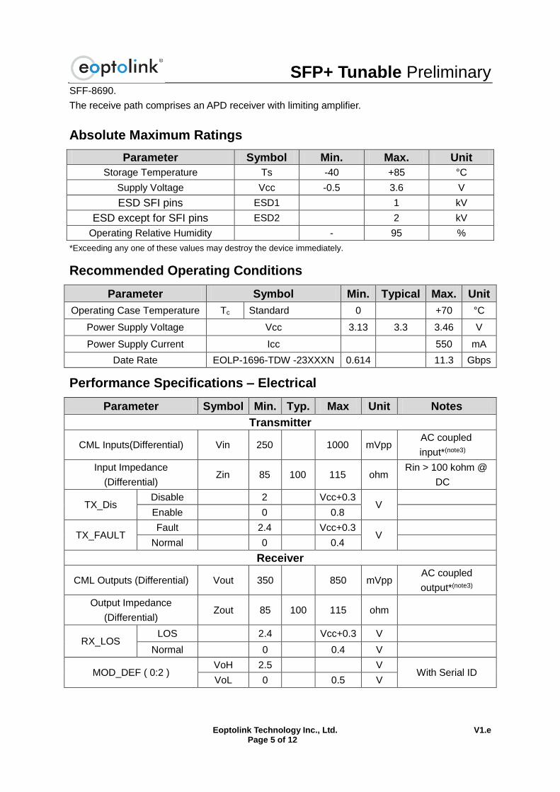
SFF-8690.
The receive path comprises an APD receiver with limiting amplifier.
Absolute Maximum Ratings
Parameter Symbol Min. Max. Unit
Storage Temperature Ts -40 +85 °C
Supply Voltage Vcc -0.5 3.6 V
ESD SFI pins ESD1 1 kV
ESD except for SFI pins ESD2 2 kV
Operating Relative Humidity - 95 %
*Exceeding any one of these values may destroy the device immediately.
Recommended Operating Conditions
Parameter Symbol Min. Typical Max. Unit
Operating Case Temperature Tc Standard 0 +70 °C
Power Supply Voltage Vcc 3.13 3.3 3.46 V
Power Supply Current Icc 550 mA
Date Rate EOLP-1696-TDW -23XXXN 0.614 11.3 Gbps
Performance Specifications – Electrical
Parameter Symbol Min. Typ. Max Unit Notes
Transmitter
CML Inputs(Differential) Vin 250 1000 mVpp AC coupled
input*(note3)
Input Impedance
(Differential) Zin 85 100 115 ohm
Rin > 100 kohm @
DC
TX_Dis Disable 2 Vcc+0.3
V
Enable 0 0.8
TX_FAULT Fault 2.4 Vcc+0.3
V
Normal 0 0.4
Receiver
CML Outputs (Differential) Vout 350 850 mVpp AC coupled
output*(note3)
Output Impedance
(Differential) Zout 85 100 115 ohm
RX_LOS LOS 2.4 Vcc+0.3 V
Normal 0 0.4 V
MOD_DEF ( 0:2 ) VoH 2.5 V
With Serial ID VoL 0 0.5 V
SFP+ Tunable Preliminary
Eoptolink Technology Inc., Ltd. V1.e Page 6 of 12
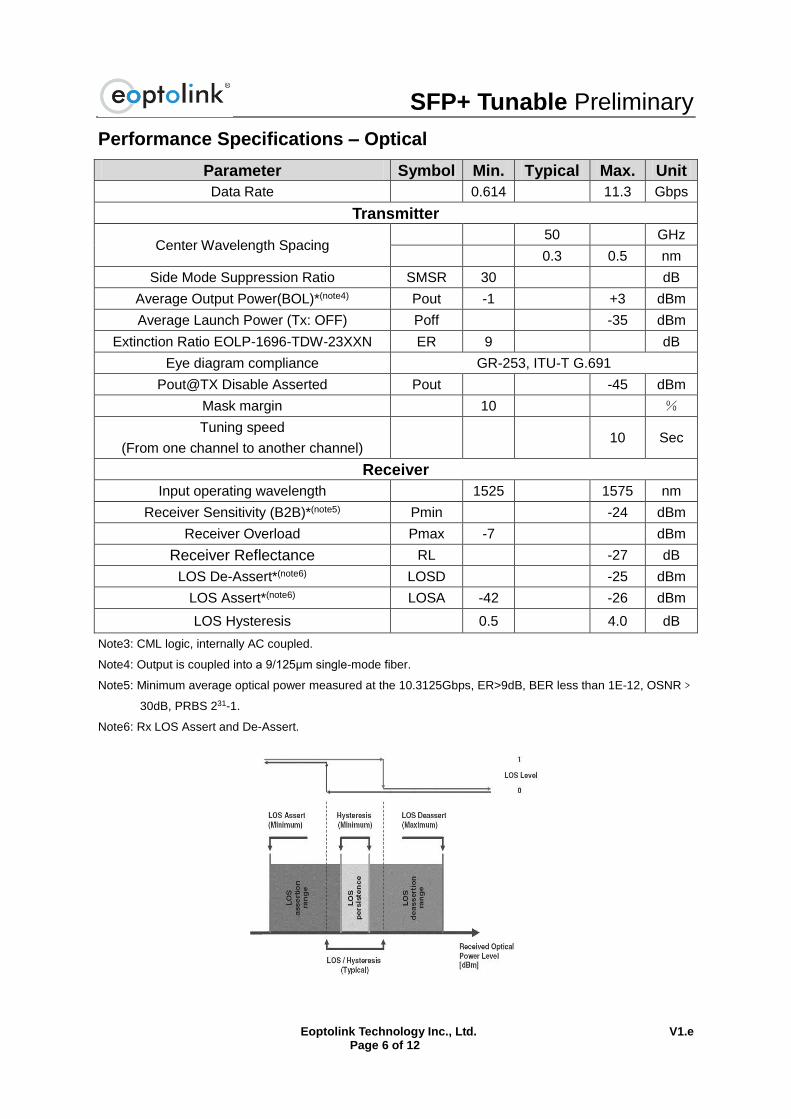
Performance Specifications – Optical
Parameter Symbol Min. Typical Max. Unit
Data Rate 0.614 11.3 Gbps
Transmitter
Center Wavelength Spacing 50 GHz
0.3 0.5 nm
Side Mode Suppression Ratio SMSR 30 dB
Average Output Power(BOL)*(note4) Pout -1 +3 dBm
Average Launch Power (Tx: OFF) Poff -35 dBm
Extinction Ratio EOLP-1696-TDW-23XXN ER 9 dB
Eye diagram compliance GR-253, ITU-T G.691
Pout@TX Disable Asserted Pout -45 dBm
Mask margin 10 %
Tuning speed
(From one channel to another channel) 10 Sec
Receiver
Input operating wavelength 1525 1575 nm
Receiver Sensitivity (B2B)*(note5) Pmin -24 dBm
Receiver Overload Pmax -7 dBm
Receiver Reflectance RL -27 dB
LOS De-Assert*(note6) LOSD -25 dBm
LOS Assert*(note6) LOSA -42 -26 dBm
LOS Hysteresis 0.5 4.0 dB
Note3: CML logic, internally AC coupled.
Note4: Output is coupled into a 9/125μm single-mode fiber.
Note5: Minimum average optical power measured at the 10.3125Gbps, ER>9dB, BER less than 1E-12, OSNR﹥
30dB, PRBS 231-1.
Note6: Rx LOS Assert and De-Assert.
SFP+ Tunable Preliminary
Eoptolink Technology Inc., Ltd. V1.e Page 7 of 12
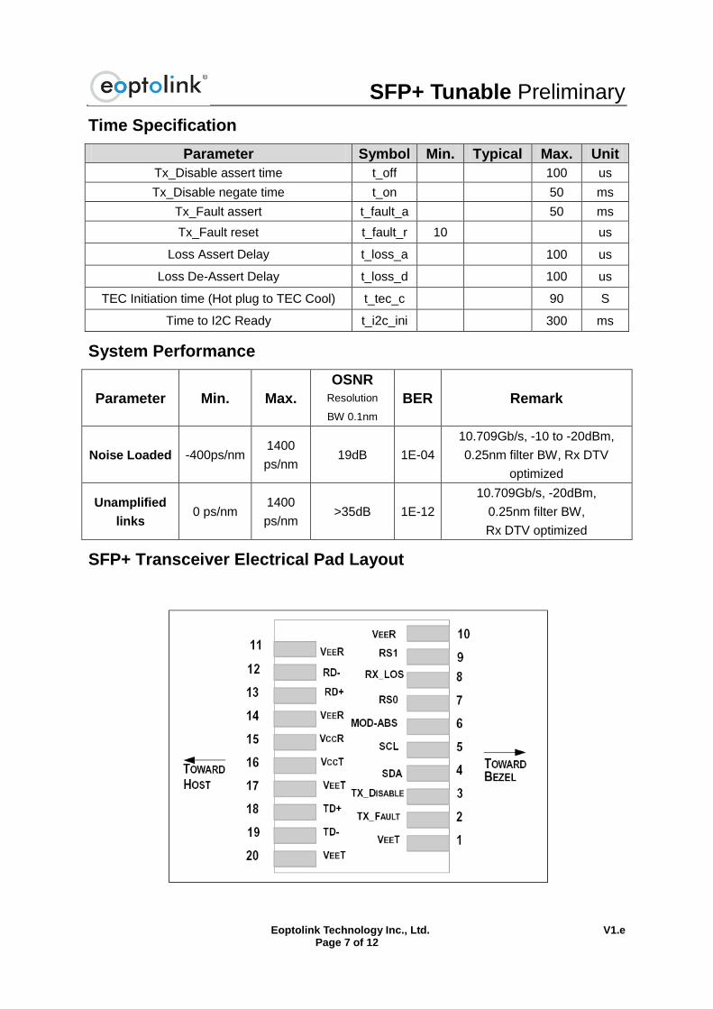
Time Specification
Parameter Symbol Min. Typical Max. Unit
Tx_Disable assert time t_off 100 us
Tx_Disable negate time t_on 50 ms
Tx_Fault assert t_fault_a 50 ms
Tx_Fault reset t_fault_r 10 us
Loss Assert Delay t_loss_a 100 us
Loss De-Assert Delay t_loss_d 100 us
TEC Initiation time (Hot plug to TEC Cool) t_tec_c 90 S
Time to I2C Ready t_i2c_ini 300 ms
System Performance
Parameter Min. Max.
OSNR
Resolution
BW 0.1nm
BER Remark
Noise Loaded -400ps/nm 1400
ps/nm 19dB 1E-04
10.709Gb/s, -10 to -20dBm,
0.25nm filter BW, Rx DTV
optimized
Unamplified
links 0 ps/nm
1400
ps/nm >35dB 1E-12
10.709Gb/s, -20dBm,
0.25nm filter BW,
Rx DTV optimized
SFP+ Transceiver Electrical Pad Layout
SFP+ Tunable Preliminary
Eoptolink Technology Inc., Ltd. V1.e Page 8 of 12
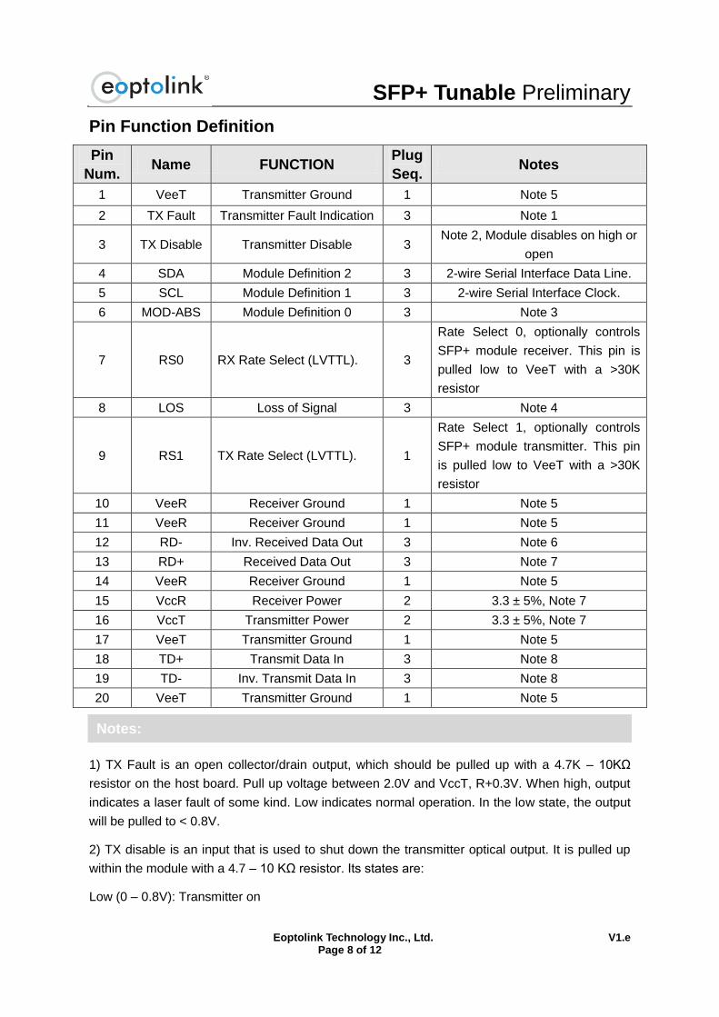
Pin Function Definition
Pin
Num. Name FUNCTION
Plug
Seq. Notes
1 VeeT Transmitter Ground 1 Note 5
2 TX Fault Transmitter Fault Indication 3 Note 1
3 TX Disable Transmitter Disable 3 Note 2, Module disables on high or
open
4 SDA Module Definition 2 3 2-wire Serial Interface Data Line.
5 SCL Module Definition 1 3 2-wire Serial Interface Clock.
6 MOD-ABS Module Definition 0 3 Note 3
7 RS0 RX Rate Select (LVTTL). 3
Rate Select 0, optionally controls
SFP+ module receiver. This pin is
pulled low to VeeT with a >30K
resistor
8 LOS Loss of Signal 3 Note 4
9 RS1 TX Rate Select (LVTTL). 1
Rate Select 1, optionally controls
SFP+ module transmitter. This pin
is pulled low to VeeT with a >30K
resistor
10 VeeR Receiver Ground 1 Note 5
11 VeeR Receiver Ground 1 Note 5
12 RD- Inv. Received Data Out 3 Note 6
13 RD+ Received Data Out 3 Note 7
14 VeeR Receiver Ground 1 Note 5
15 VccR Receiver Power 2 3.3 ± 5%, Note 7
16 VccT Transmitter Power 2 3.3 ± 5%, Note 7
17 VeeT Transmitter Ground 1 Note 5
18 TD+ Transmit Data In 3 Note 8
19 TD- Inv. Transmit Data In 3 Note 8
20 VeeT Transmitter Ground 1 Note 5
1) TX Fault is an open collector/drain output, which should be pulled up with a 4.7K – 10KΩ
resistor on the host board. Pull up voltage between 2.0V and VccT, R+0.3V. When high, output
indicates a laser fault of some kind. Low indicates normal operation. In the low state, the output
will be pulled to < 0.8V.
2) TX disable is an input that is used to shut down the transmitter optical output. It is pulled up
within the module with a 4.7 – 10 KΩ resistor. Its states are:
Low (0 – 0.8V): Transmitter on
Notes:
SFP+ Tunable Preliminary
Eoptolink Technology Inc., Ltd. V1.e Page 9 of 12
(>0.8, < 2.0V): Undefined
High (2.0 – 3.465V): Transmitter Disabled
Open: Transmitter Disabled
3) Module absent, connected to VEET or VEER in the module.
4) LOS (Loss of Signal) is an open collector/drain output, which should be pulled up with a 4.7K –
10KΩ resistor. Pull up voltage between 2.0V and VccT, R+0.3V. When high, this output indicates
the received optical power is below the worst-case receiver sensitivity (as defined by the
standard in use). Low indicates normal operation. In the low state, the output will be pulled to <
0.8V.
5) The module signal ground contacts, VeeR and VeeT, should be isolated from the module case
6) RD-/+: These are the differential receiver outputs. They are AC coupled 100Ω differential lines
which should be terminated with 100Ω (differential) at the user SERDES. The AC coupling is
done inside the module and is thus not required on the host board.
7) VccR and VccT are the receiver and transmitter power supplies. They are defined as 3.3V
±5% at the SFP+ connector pin. Inductors with DC resistance of less than 1 ohm should be used
in order to maintain the required voltage at the SFP+ input pin with 3.3V supply voltage. VccR
and VccT may be internally connected within the SFP+ transceiver module.
8) TD-/+: These are the differential transmitter inputs. They are AC-coupled, differential lines with
100Ω differential termination inside the module. The AC coupling is done inside the module and
is thus not required on the host board.
Please reference SFF-8690 – Tunable SFP+ Memory Map for ITU Frequencies
EEPROM
SFP+ Tunable Preliminary
Eoptolink Technology Inc., Ltd. V1.e Page 10 of 12
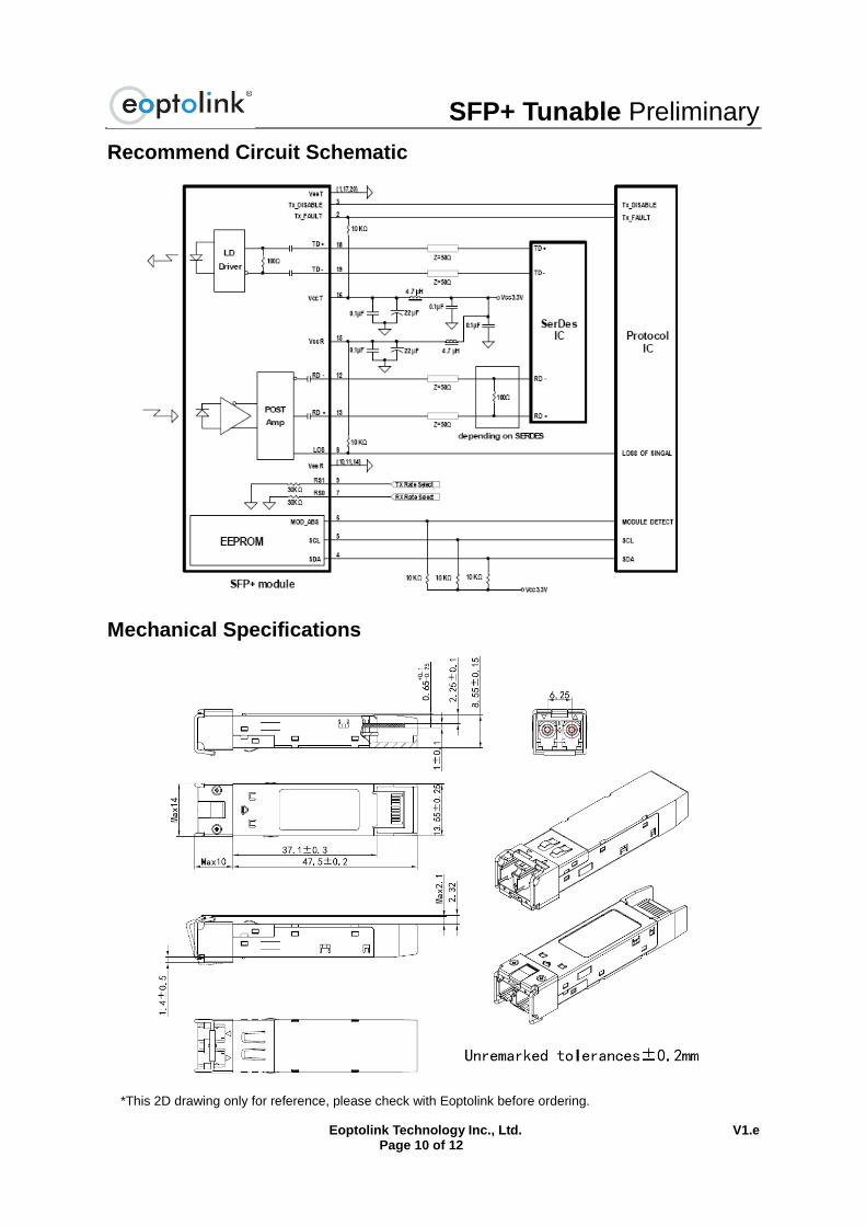
Recommend Circuit Schematic
Mechanical Specifications
*This 2D drawing only for reference, please check with Eoptolink before ordering.
SFP+ Tunable Preliminary
Eoptolink Technology Inc., Ltd. V1.e Page 11 of 12
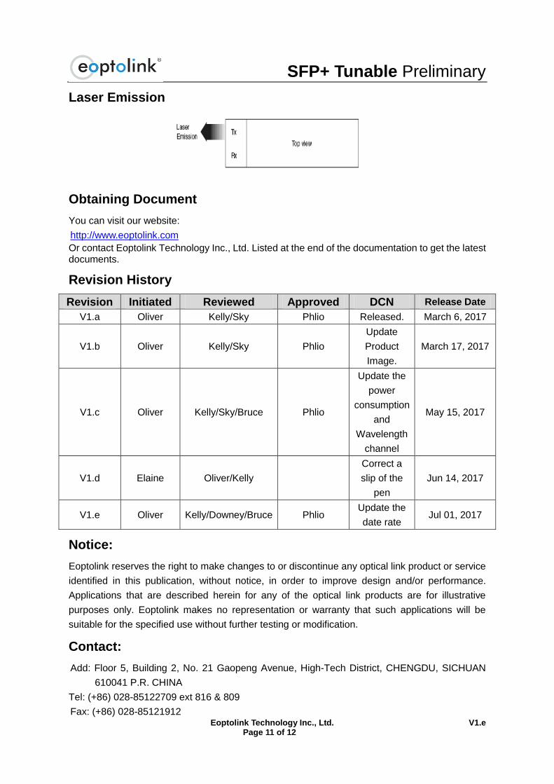
Laser Emission
Obtaining Document
You can visit our website:
http://www.eoptolink.com
Or contact Eoptolink Technology Inc., Ltd. Listed at the end of the documentation to get the latest documents.
Revision History
Revision Initiated Reviewed Approved DCN Release Date
V1.a Oliver Kelly/Sky Phlio Released. March 6, 2017
V1.b Oliver Kelly/Sky Phlio
Update
Product
Image.
March 17, 2017
V1.c Oliver Kelly/Sky/Bruce Phlio
Update the
power
consumption
and
Wavelength
channel
May 15, 2017
V1.d Elaine Oliver/Kelly
Correct a
slip of the
pen
Jun 14, 2017
V1.e Oliver Kelly/Downey/Bruce Phlio Update the
date rate Jul 01, 2017
Notice:
Eoptolink reserves the right to make changes to or discontinue any optical link product or service
identified in this publication, without notice, in order to improve design and/or performance.
Applications that are described herein for any of the optical link products are for illustrative
purposes only. Eoptolink makes no representation or warranty that such applications will be
suitable for the specified use without further testing or modification.
Contact:
Add: Floor 5, Building 2, No. 21 Gaopeng Avenue, High-Tech District, CHENGDU, SICHUAN
610041 P.R. CHINA
Tel: (+86) 028-85122709 ext 816 & 809
Fax: (+86) 028-85121912
SFP+ Tunable Preliminary
Eoptolink Technology Inc., Ltd. V1.e Page 12 of 12
Postal: 610041
E-mail:[email protected]
http://www.eoptolink.com