SERVICE MANUAL 200/250 TON ELEVATOR/SPIDER 1.5a 6-6-2011 6 SECTION II INSTALLATION 2-1. COMPONENTS...
46
SERVICE MANUAL 200/250 TON ELEVATOR/SPIDER 200/250 TON MANUAL ELEVATOR BVM CORPORATION 430 S. Navajo St. Denver, CO 80223 Phone: 303-975-1402 Fax: 303-975-0981 E-Mail: [email protected]
Transcript of SERVICE MANUAL 200/250 TON ELEVATOR/SPIDER 1.5a 6-6-2011 6 SECTION II INSTALLATION 2-1. COMPONENTS...
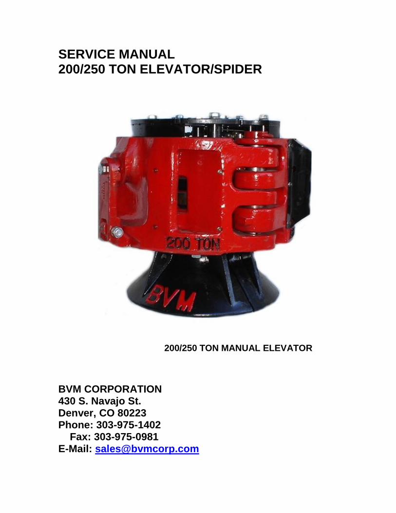
SERVICE MANUAL 200/250 TON ELEVATOR/SPIDER
200/250 TON MANUAL ELEVATOR
BVM CORPORATION 430 S. Navajo St. Denver, CO 80223 Phone: 303-975-1402 Fax: 303-975-0981 E-Mail: [email protected]
VERSION 1.5a 6-6-2011 2
200/250 TON - CASING ELEVATOR/SPIDER
TABLE OF CONTENTS Section No. Page I DESCRIPTION…………………......... 4 1-1. Introduction…………………….... 4 1-3. Controls………………………..... 4 1-4. Specification………................... 5 II INSTALLATION………………………. 6 2-1. Components……………………. 6 2-2. Installing/Removing Slips……… 6 2-3. Installing/Removing Guides… ... 7
2-4. Installing Elevator…………... …. 8 2-5. Installing Spider……………....… 9 III OPERATION……………………..…… 10
3-1. Operation………………..…..……10 3-2. Setting Slips………………….. ... 10 3-3. Raising Slips……………………. 10
IV LUBRICATION……………………… . 11 4-1. Lubrication……………….… ….. 11 V MAINTENACE………....................... 12 5-1. Preventive Maintenance…….... 12 5-3. Troubleshooting……………...... 12 VI DISASSEMBLY & ASSEMBLY…….. 13 6-1. Dissassembly………….............. 13 6-2. Assembly……………………...... 13 VII PARTS LISTS………………………... 17
7-1. Parts Lists………….………….... 17 7-2. 200/250 Ton Spider
Assembly…….. 19 7-3. 200/250 Ton Elevator
Assembly…... 19 7-4. 200/250 Ton Elevator/Spider
Basic Assembly……………...21 7-5. Beam Lifting Lever Assembly….23 7-6. Latch Assembly………………....24 7-7. Leveling Beam Assembly……...25 7-8. Mulit-Insert Slip Assembly……..26 7-9. Double/Single Slip Assembly….28 7-10. 200/250 Ton Elevator/Spider Slip
Assemblies, Guides and Inserts…………………..……30
7-11. 200/250 Ton Elevator/Spider Accessories………………….31
7-12. 200/250 Ton Elevator/Spider
Foreign Spare Parts………..31
Section No. Page VIII PNEUMATIC OPERATIONS….35
8-1. Operations………………...33 8-2. Raising Slips………….…..33 8-3. Setting Slips……………….33 8-4. Air Operated Parts Lists....35 8-5. 200/250 Ton Air Operated Spider
Assembly………………35 8-6. 200/250 Ton Air Operated
Elevator Assembly…….36 8-7. 200/250 Ton Air Operated
Elevator/Spider Assy….38 8-8. Air Operated Latch
Assembly……….……...43 8-9. Air Operated Leveling
Beam Assembly……….44 8-10. Air Operated Mulit-Insert
Slip Assembly…………45 8-11. Air Operated Double/Single
Slip Assembly………....45 8-12. 200/250 Ton Air Operated
Elevator/Spider Slip Assemblies, Guides and Inserts…………………..45
8-13. 200/250 Ton Air Operated Elevator/Spider Accessories……………45
8-14. 200/250 Ton Air Operated Elevator/Spider Foreign Spare Parts……………46
VERSION 1.5a 6-6-2011 3
LIST OF TABLES Table No. Title Page 1-1. Specifications………………………...…....5 4-1. Lubrication Schedule……..………………11 5-3. Troubleshooting……………..……………12 6-1. 200/250 Ton Spider Assembly………….14 6-2. 200/250 Ton Elevator Assembly………. 14 6-3. 200/250 Ton Elevator/Spider Assy…..…15 7-2. 200/250 Ton Spider Parts List Index…. 18 7-3. 200/250 Ton Elevator Parts List Index....20 7-4. 200/250 Ton Elevator/Spider Parts List Index……………………………....22 7-5. Beam Lifting Lever Parts List Index…..…23 7-6. Latch Part List Index……………………...24 7-7. Leveling vParts List Index…………..…....25 7-8. Multi-Insert Slip Part List Index………..…27 7-9. Double/Single Slip Part List Index…..…...29 7-10. 200/250 Ton Elevator/Spider Slip
Assemblies, Guides & Inserts………..29 7-11. 200/250 Ton Elevator/Spider
Accessories………………………….....31 7-12. 200/250 Ton Elevator/Spider Foreign
Spare Parts……………………….…….31 8-2. 200/250 Ton Air Operating Spider Parts List
Index…………………………………….35 8-3. 200/250 Ton Air Operating Elevator Parts List Index …………………………………..... 37 8-4. 200/250 Ton Air Operating Elevator/Spider Parts List Index…….…………………..41 8-5. Air Operating Latch Part List Index…...….43 8-6. Air Operating Leveling Beam Parts List Index…………………………………….45
LIST OF ILLUSTRATIONS Figure No. Title Page 1-1. Description…………………………....4 1-2. Specifications………………………....5 2-1. Components…………………………..6 2-2. Slip Detail……………………………...6 2-3. Double/Single Inserts………………..7 2-4. Elevator Guides……………………....7 2-5. Spider Guides………………………...7 2-6. Typical Installation……………….…..8 2-7. Standard Derrick Installation………..8 2-8. Jackknife Derrick Installation……….8 2-9. Spider/Adaptor Plate Installation…..9 3-1. Operating Detail……………………..10 4-1. Lubrication Points…………………...11 7-2. 200/250 Ton Spider Assembly…... 17 7-3. 200/250 Ton Elevator Assembly…..19 7-4. 200/250 Ton Elevator/Spider Assy. 21 7-5. Beam Lifting Lever Assembly…….. 23 7-6. Latch Assembly…………………..…24 7-7. Leveling Beam Assembly……….…25 7-8. Multi-Insert Slips…………………....26 7-9. Double/Single Insert Slips………….28 8-1. 200/250 Ton Air Operation Details……..33 8-2. 200/250 Ton Air Operating Spider
Assembly……………………......34 8-3. 200/250 Ton Air Operating Elevator
Assembly………………………...36 8-4. 200/250 Ton Air Operating Elevator/Spider Assembly……..38 8-5. Air Operating Latch Assembly…..…43 8-6. Air Operating Leveling Beam
Assembly……………….………..44
VERSION 1.5a 6-6-2011 4
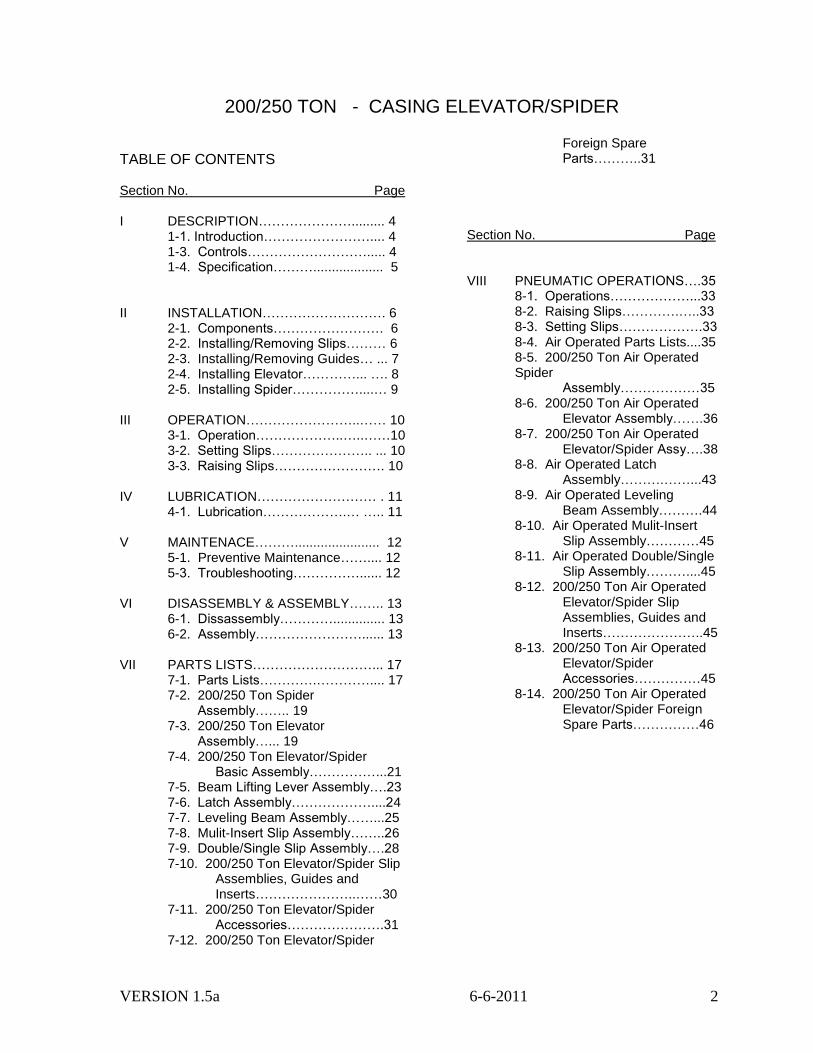
SECTION I DESCRIPTION INTRODUCTION 1-1. The BVM 200/250 Ton Casing Elevator/Spider can handle ten different casing diameters from 2 3/8 to 7 5/8 inches using four slip assemblies, inserts and proper size guides. The 200/250 ton body can be dressed as a casing elevator or spider, depending on accessories fitted. 1-2. Both configurations consist of four slips mounted on two leveling beams. The leveling beams ride up and down on guide rods and serve to keep the slips in level position and riding simultaneously. CONTROLS 1-3. Two simple controls make manual operation easy. The slips are easily raised by hand with the 2 ½ foot lever bar provided, requiring no more than 60 pound of force. An optional foot pedal is available for the spider. Slips lock in either the raised, or the set positions. 1. Latch Handle: Operates the locking mechanism. Raise the latch handle and the slips will drop into the bowl by gravity, grip casing and lock. Lower the latch handle to unlock the slips from their set position. 2. Lifting Lever: Fits in socket and is used to raise the slips when force is applied. An optional foot pedal is available to replace the lever when the tool is dressed as a spider.
Figure 1-1. Description
VERSION 1.5a 6-6-2011 5
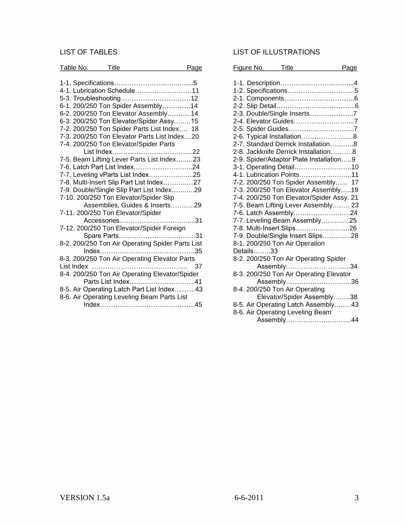
1-4. SPECIFICATIONS
Figure 1-2. Specifications
Table 1-1. Specifications
Item English Metric
Casing Size Range - Diameter 2-3/8 - 7-5/8 in 60.3 - 193.7 mm
Maximum Safe Hook Load Weight 400,000 lb 181,400 kg
Weight, Elevator with Bell Guide (less slips and guides)
2145 lb 975 kg
Weight, Spider (less slips and guides) 1950 lb 900 kg
Spider Adaptor Plate
Dimensions 38.5 in dia X 2 in 977 mm dia X 50.8 mm
Weight 435 lb 198 kg
VERSION 1.5a 6-6-2011 6
SECTION II INSTALLATION
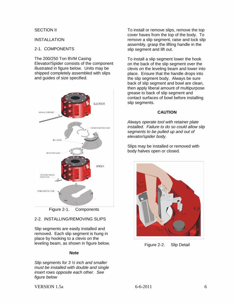
2-1. COMPONENTS The 200/250 Ton BVM Casing Elevator/Spider consists of the component illustrated in figure below. Units may be shipped completely assembled with slips and guides of size specified.
Figure 2-1. Components
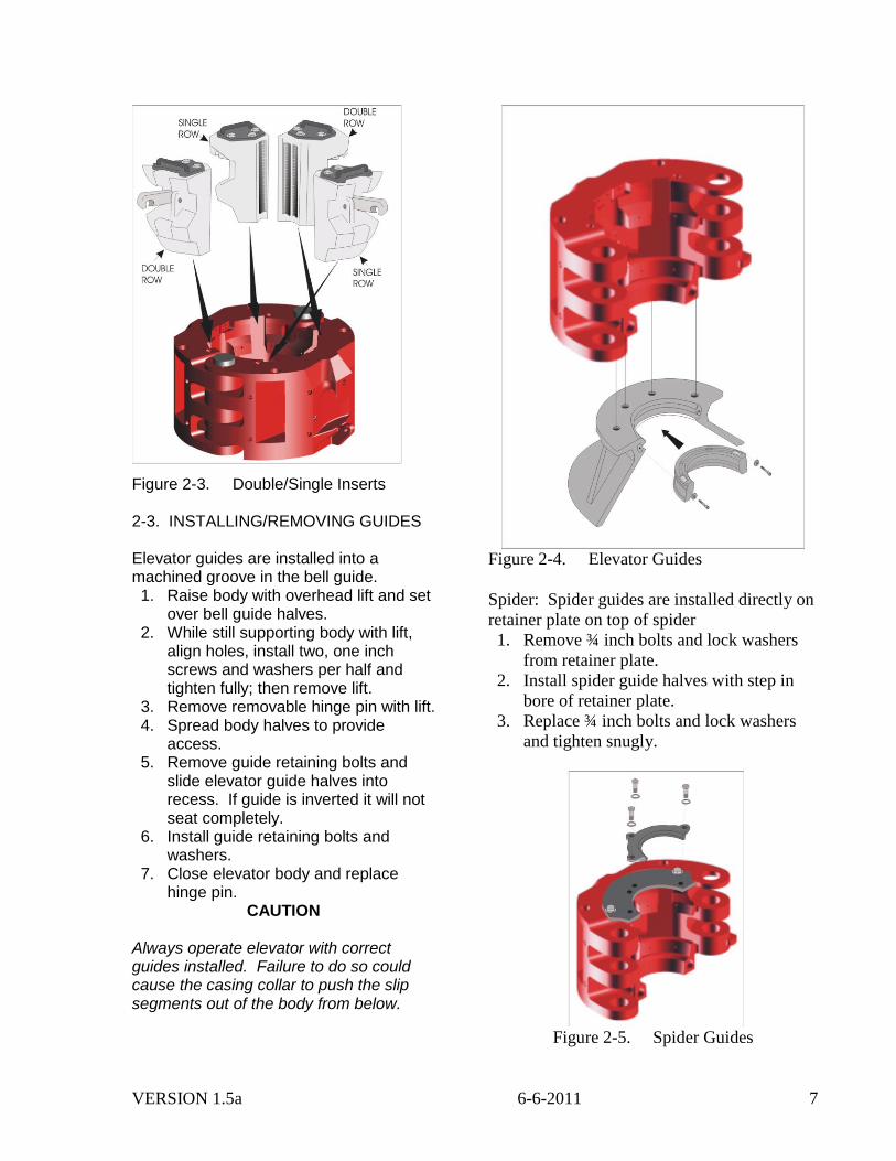
2-2. INSTALLING/REMOVING SLIPS Slip segments are easily installed and removed. Each slip segment is hung in place by hooking to a clevis on the leveling beam, as shown in figure below.
To install or remove slips, remove the top cover haves from the top of the body. To remove a slip segment, raise and lock slip assembly, grasp the lifting handle in the slip segment and lift out. To install a slip segment lower the hook on the back of the slip segment over the clevis on the leveling beam and lower into place. Ensure that the handle drops into the slip segment body. Always be sure back of slip segment and bowl are clean, then apply liberal amount of multipurpose grease to back of slip segment and contact surfaces of bowl before installing slip segments.
CAUTION Always operate tool with retainer plate installed. Failure to do so could allow slip segments to be pulled up and out of elevator/spider body. Slips may be installed or removed with body halves open or closed.
Figure 2-2. Slip Detail
Note Slip segments for 3 ½ inch and smaller must be installed with double and single insert rows opposite each other. See figure below
VERSION 1.5a 6-6-2011 7
Figure 2-3. Double/Single Inserts 2-3. INSTALLING/REMOVING GUIDES Elevator guides are installed into a machined groove in the bell guide. 1. Raise body with overhead lift and set
over bell guide halves. 2. While still supporting body with lift,
align holes, install two, one inch screws and washers per half and tighten fully; then remove lift.
3. Remove removable hinge pin with lift. 4. Spread body halves to provide
access. 5. Remove guide retaining bolts and
slide elevator guide halves into recess. If guide is inverted it will not seat completely.
6. Install guide retaining bolts and washers.
7. Close elevator body and replace hinge pin.
CAUTION Always operate elevator with correct guides installed. Failure to do so could cause the casing collar to push the slip segments out of the body from below.
Figure 2-4. Elevator Guides
Spider: Spider guides are installed directly on
retainer plate on top of spider
1. Remove ¾ inch bolts and lock washers
from retainer plate.
2. Install spider guide halves with step in
bore of retainer plate.
3. Replace ¾ inch bolts and lock washers
and tighten snugly.
Figure 2-5. Spider Guides
VERSION 1.5a 6-6-2011 8
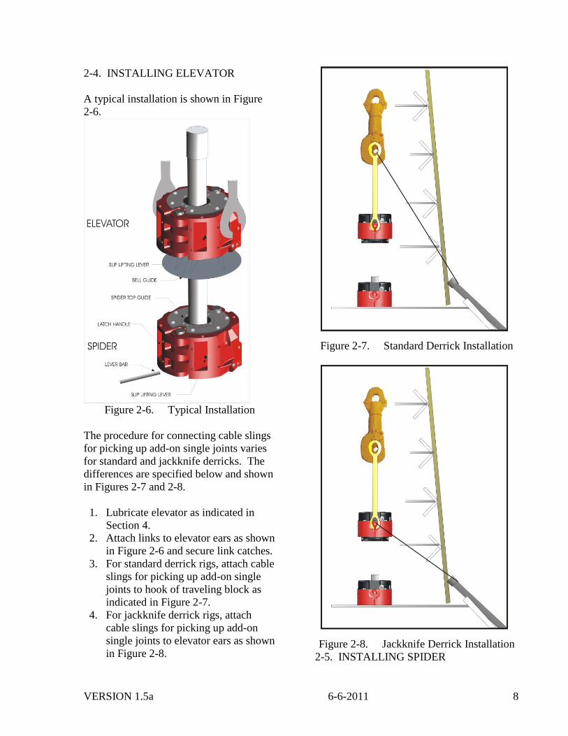
2-4. INSTALLING ELEVATOR
A typical installation is shown in Figure
2-6.
Figure 2-6. Typical Installation
The procedure for connecting cable slings
for picking up add-on single joints varies
for standard and jackknife derricks. The
differences are specified below and shown
in Figures 2-7 and 2-8.
1. Lubricate elevator as indicated in
Section 4.
2. Attach links to elevator ears as shown
in Figure 2-6 and secure link catches.
3. For standard derrick rigs, attach cable
slings for picking up add-on single
joints to hook of traveling block as
indicated in Figure 2-7.
4. For jackknife derrick rigs, attach
cable slings for picking up add-on
single joints to elevator ears as shown
in Figure 2-8.
Figure 2-7. Standard Derrick Installation
Figure 2-8. Jackknife Derrick Installation
2-5. INSTALLING SPIDER
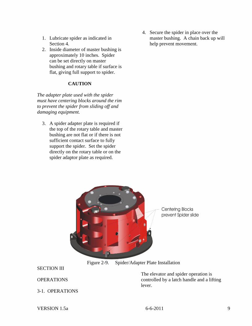
VERSION 1.5a 6-6-2011 9
1. Lubricate spider as indicated in
Section 4.
2. Inside diameter of master bushing is
approximately 10 inches. Spider
can be set directly on master
bushing and rotary table if surface is
flat, giving full support to spider.
CAUTION
The adapter plate used with the spider
must have centering blocks around the rim
to prevent the spider from sliding off and
damaging equipment.
3. A spider adapter plate is required if
the top of the rotary table and master
bushing are not flat or if there is not
sufficient contact surface to fully
support the spider. Set the spider
directly on the rotary table or on the
spider adaptor plate as required.
4. Secure the spider in place over the
master bushing. A chain back up will
help prevent movement.
Figure 2-9. Spider/Adapter Plate Installation
SECTION III
OPERATIONS
3-1. OPERATIONS
The elevator and spider operation is
controlled by a latch handle and a lifting
lever.
VERSION 1.5a 6-6-2011 10
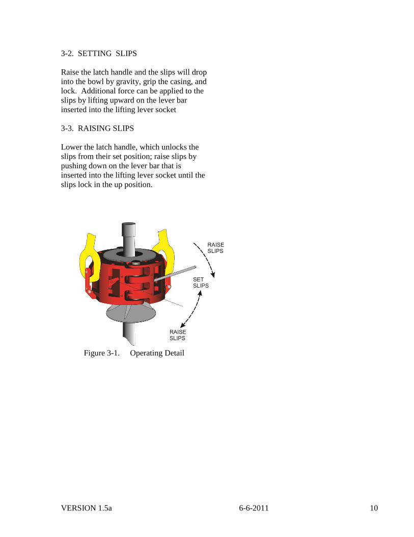
3-2. SETTING SLIPS
Raise the latch handle and the slips will drop
into the bowl by gravity, grip the casing, and
lock. Additional force can be applied to the
slips by lifting upward on the lever bar
inserted into the lifting lever socket
3-3. RAISING SLIPS
Lower the latch handle, which unlocks the
slips from their set position; raise slips by
pushing down on the lever bar that is
inserted into the lifting lever socket until the
slips lock in the up position.
Figure 3-1. Operating Detail
VERSION 1.5a 6-6-2011 11
SECTION IV
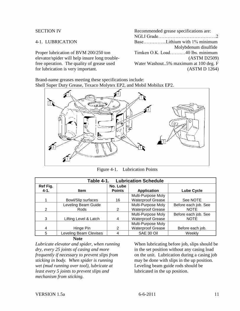
4-1. LUBRICATION
Proper lubrication of BVM 200/250 ton
elevator/spider will help insure long trouble-
free operation. The quality of grease used
for lubrication is very important.
Recommended grease specifications are:
NGLI Grade……………………………….2
Base…………...Lithium with 1% minimum
Molybdenum disulfide
Timken O.K. Load…….…40 lbs. minimum
(ASTM D2509)
Water Washout..5% maximum at 100 deg. F
(ASTM D 1264)
Brand-name greases meeting these specifications include:
Shell Super Duty Grease, Texaco Molytex EP2, and Mobil Mobilux EP2.
Figure 4-1. Lubrication Points
Table 4-1. Lubrication Schedule Ref Fig.
4-1. Item No. Lube
Points Application Lube Cycle
1 Bowl/Slip surfaces 16 Multi-Purpose Moly Waterproof Grease See NOTE
2 Leveling Beam Guide
Rods 2 Multi-Purpose Moly Waterproof Grease
Before each job. See NOTE
3 Lifting Level & Latch 4 Multi-Purpose Moly Waterproof Grease
Before each job. See NOTE
4 Hinge Pin 2 Multi-Purpose Moly Waterproof Grease Before each job.
5 Leveling Beam Clevises 4 SAE 30 Oil Weekly
Note
Lubricate elevator and spider, when running
dry, every 25 joints of casing and more
frequently if necessary to prevent slips from
sticking in body. When spider is running
wet (mud running over tool), lubricate at
least every 5 joints to prevent slips and
mechanism from sticking.
When lubricating before job, slips should be
in the set position without any casing load
on the unit. Lubrication during a casing job
may be done with slips in the up position.
Leveling beam guide rods should be
lubricated in the up position.
VERSION 1.5a 6-6-2011 12
SECTION V
MAINTENANCE
5-1. PREVENTIVE MAINTANCE
DO’S_______________________________
1. Lubricate as required in Table 4-1.
2. Check guides and gripping inserts
for wear and replace as required.
3. Avoid unnecessary shock loading of
slip segments.
DON’TS____________________________
1. Never paint over moving parts, backs
of slip segments, the inside of the
bowl or grease fittings.
2. Never use equipment that is not
operating properly.
5-2. Always protect the surface of the backs
of the slips and inside of the bowl against
corrosion by keeping them clean and well
lubricated with multi-purpose waterproof
grease.
5-3. TROUBLESHOOTING
Table 5-3. Troubleshooting
Symptom Possible Cause Remedy Slip segments do not operate or are difficult to operate in both directions.
Malfunction of lifting lever mechanism.
Inspect lifting lever for dirt, contamination or breakage of components. Clean and replace as necessary.
Lock will not catch when raising slips.
Mud has flowed over tool & gotten into lock and lock slot, preventing it from moving fully outward.
Pump grease through leveling beam guide rod to force mud out.
Slips do not lock in the up or down position.
Latch handle mechanism malfunctions.
Check for dirt, contamination or breakage of components in latch handle mechanism. Clean and replace as necessary.
Pipe slips. Incorrect slip segments mixed with correct size slips segments.
Install correct size slip segments.
Worn or re-sharpened inserts. Replace worn or re-sharpened inserts with new inserts.
Worn slip segments or inserts allowing slip to set too low in bowl, thereby preventing inserts from gripping pipe.
Inspect slip segments for wear, galling or cracking and inspect bowl for damage. Correct and repair as necessary.
Damaged Pipe. Incorrect slip segment in slip segment group.
Install correct size slip segments.
Worn or re-sharpened inserts. Replace worn or re-sharpened inserts with new inserts.
Slips sticking in bowls. Inadequate lubrication. Clean backs of the slip segments and bowl and lubricate properly.
Galling and pitting of slip segments or bowls.
Redress slips and bowls (should be done by factory but can be done by carefully using a flexible sanding disc and lightly smoothing surface) and protect against corrosion with proper lubrication. Find and correct cause of galling.
VERSION 1.5a 6-6-2011 13
SECTION VI
DISASSEMBLY & ASSEMBLY
6-1. DISASSEMBLY
Disassembly is presented in Tables 6-1
through 6-3 with the components of the
200/250 Ton Elevator/Spider listed in
disassembly sequence. The tables start with
a complete assembly and end with a bare
body. It is not necessary to start at the
beginning and work through the tables for
every task. Locate the part to be worked on
and start at that point. Notes are provided
where applicable to reference or explain a
detail for the particular step of disassembly
or assembly. When used in the reverse
order, the tables provide assembly
information as well as disassembly
information.
6-2. ASSEMBLY
Assembly of the 200/250 Ton
Elevator/Spider can be performed by
following the reverse order of Tables 6-1
through 6-3. Notes peculiar to a particular
step are provided to highlight critical
assembly information such as adjustment or
torque values.
VERSION 1.5a 6-6-2011 14
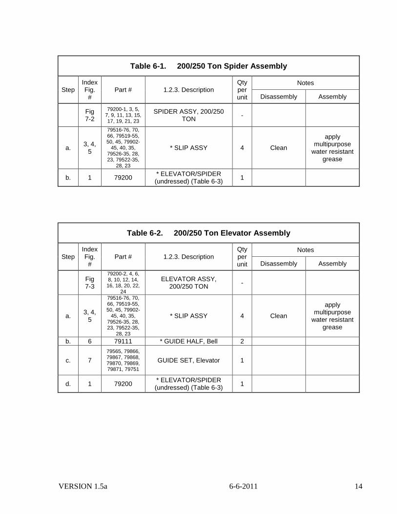
Table 6-1. 200/250 Ton Spider Assembly
Step Index Fig. #
Part # 1.2.3. Description Qty per unit
Notes
Disassembly Assembly
Fig 7-2
79200-1, 3, 5, 7, 9, 11, 13, 15, 17, 19, 21, 23
SPIDER ASSY, 200/250 TON
-
a. 3, 4,
5
79516-76, 70, 66, 79519-55, 50, 45, 79902-
45, 40, 35, 79526-35, 28, 23, 79522-35,
28, 23
* SLIP ASSY 4 Clean
apply multipurpose
water resistant grease
b. 1 79200 * ELEVATOR/SPIDER (undressed) (Table 6-3)
1
Table 6-2. 200/250 Ton Elevator Assembly
Step Index Fig. #
Part # 1.2.3. Description Qty per unit
Notes
Disassembly Assembly
Fig 7-3
79200-2, 4, 6, 8, 10, 12, 14,
16, 18, 20, 22, 24
ELEVATOR ASSY, 200/250 TON
-
a. 3, 4,
5
79516-76, 70, 66, 79519-55, 50, 45, 79902-
45, 40, 35, 79526-35, 28, 23, 79522-35,
28, 23
* SLIP ASSY 4 Clean
apply multipurpose
water resistant grease
b. 6 79111 * GUIDE HALF, Bell 2
c. 7
79565, 79866, 79867, 79868, 79870, 79869, 79871, 79751
GUIDE SET, Elevator 1
d. 1 79200 * ELEVATOR/SPIDER (undressed) (Table 6-3)
1

VERSION 1.5a 6-6-2011 15
Table 6-3. 200/250 Ton Elevator/Spider Assembly
Step Index Fig. #
Part # 1.2.3. Description Qty per unit
Notes
Disassembly Assembly
Fig 7-4
79200 ELEVATOR/SPIDER ASSY
(undressed) Ref.
a. 17 79803 * CATCH, Link Ref.
b. 16 18180-16-5 * SCREW, Shoulder Hex
Head 2
c. 14 79121 * PIN ASSY, Removable
Hinge 1
Inspect for wear.
Install new if worn.
d. 15 79124 * PIN ASSY, Stationary
Hinge 1
e. 36 79521 * PLATE, Retainer 2
f. 32 79126 * BLOCK, Pillow 2
g. 31 79125 * POST, Leveling Beam
Guide 2
h. 29 79609 * TANG, Leveling beam
support 1
i. 2 79882 * BUTTON, Register 8
j. 26 79615 * RETAINER, Dog 1
k. 25 79616 * SPRING, Compression 1
l. 24 79614 * LATCH, Dog 1
m. 23 79116 * BEAM ASSY, Leveling 2 Check pins for
bending.
n. 3,
Fig. 7-7
79751 * RING, Wiper 2 Discard. Install new.
o. 2,
Fig. 7-7
79728 * BUSHING 2
VERSION 1.5a 6-6-2011 16
Table 6-3 (con't). 200/250 Ton Elevator/Spider Assembly
Step Index Fig. #
Part # 1.2.3. Description Qty per unit
Notes
Disassembly Assembly
p 1,
Fig. 7-7
79722 * BEAM ASSEMBLY 1
q. 9 79585 * PIVOT, Lever 1
r. 7 79090 * LEVER ASSY, Beam
Lifting 1
s. 2,
Fig. 7-5
79681 * FOLLOWER, Cam 1
t. 1,
Fig. 7-5
79136 * BEAM, Lifting 1
u. 10 79680 * LATCH ASSY 1
v. 11 79102 * SCREW, Toggle 1
w. 5,
Fig. 7-6
79683 * SPRING BLOCK 1
x. 6,
Fig. 7-6
79682 * SPRING, Compression 1
w. 12, Fig. 7-6
79604-7-S * PIN, Spring 1 Install new.
z. 4,
Fig. 7-6
79684 * CLEVIS, Toggle 1
aa. 2,
Fig. 7-6
79127 * HANDLE, Latch 1
ab. 1,
Fig. 7-6
79679 * BASE ASSY, Latch 1
ac. 1 79109 * BODY 1 Check for Scoring.
Install new if damaged.
VERSION 1.5a 6-6-2011 17
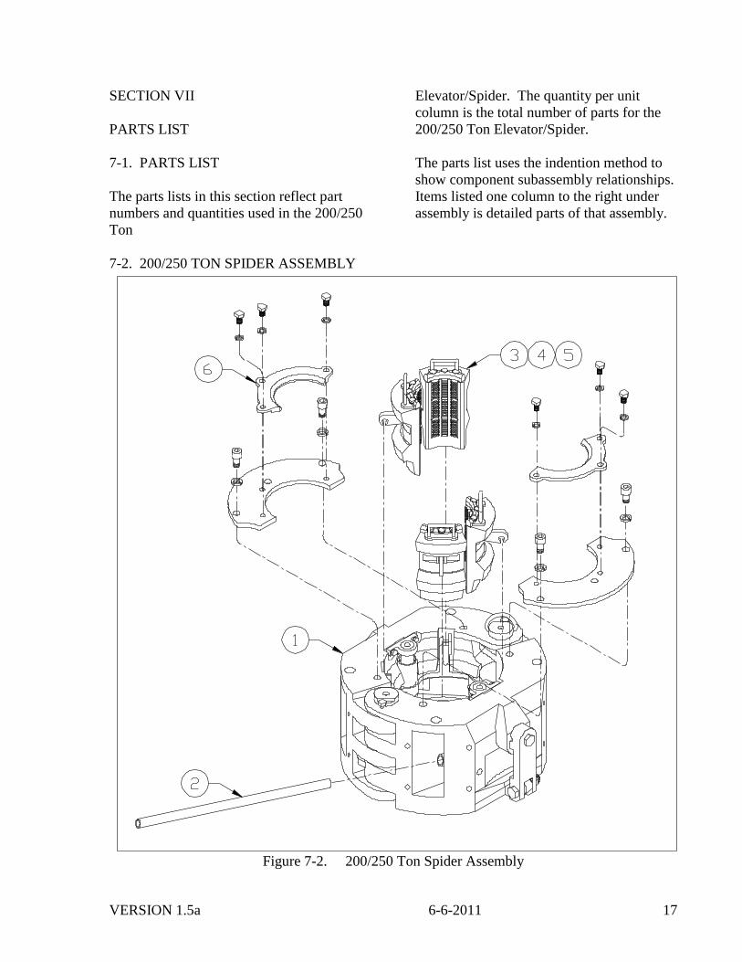
SECTION VII
PARTS LIST
7-1. PARTS LIST
The parts lists in this section reflect part
numbers and quantities used in the 200/250
Ton
Elevator/Spider. The quantity per unit
column is the total number of parts for the
200/250 Ton Elevator/Spider.
The parts list uses the indention method to
show component subassembly relationships.
Items listed one column to the right under
assembly is detailed parts of that assembly.
7-2. 200/250 TON SPIDER ASSEMBLY
Figure 7-2. 200/250 Ton Spider Assembly
VERSION 1.5a 6-6-2011 18
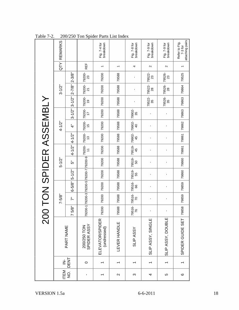
Table 7-2. 200/250 Ton Spider Parts List Index
200 T
ON
SP
IDE
R A
SS
EM
BLY
RE
MA
RK
S
Fig
. 7-4
for
bre
akdow
n
Fig
. 7-8
for
bre
akdow
n
Fig
. 7-9
for
bre
akdow
n
Fig
. 7-9
for
bre
akdow
n
Refe
r to
Fig
.
7-3
for
att
achin
g p
airs
QT
Y
RE
F
1
1
4
2
2
1
3-1
/2"
2-3
/8"
79200-
23
79200
79588
-
79522-
23
79526-
23
79525
2-7
/8"
79200-
21
79200
79588
-
79522-
28
79526-
28
79864
3-1
/2"
79200-
19
79200
79588
-
79522-
35
79526-
35
79863
4-1
/2"
3-1
/2"
79200-
17
79200
79588
79902-
35
- -
79863
4"
79200-
15
79200
79588
79902-
40
- -
79862
4-1
/2"
79200-
13
79200
79588
79902-
45
- -
79861
5-1
/2"
4-1
/2"
79200-
11
79200
79588
79519-
45
- -
79861
5"
79200-9
79200
79588
79519-
50
- -
79860
5-1
/2"
79200-7
79200
79588
79519-
55
- -
79860
7-5
/8"
6-5
/8"
79200-5
79200
79588
79516-
66
- -
79859
7"
79200-3
79200
79588
79516-
70
- -
79859
7 5
/8"
79200-1
79200
79588
79516-
76
- -
79858
PA
RT
NA
ME
200/2
50
TO
N
SP
IDE
R A
SS
Y
EL
EV
AT
OR
/SP
IDE
R
(undre
ssed)
LE
VE
R H
AN
DL
E
SLIP
AS
SY
SLIP
AS
SY
, S
ING
LE
SLIP
AS
SY
, D
OU
BLE
SP
IDE
R G
UID
E S
ET
IN
-
DE
NT
0
1
1
1
1
1
1
ITE
M
NO
.
- 1
2
3
4
5
6
VERSION 1.5a 6-6-2011 19
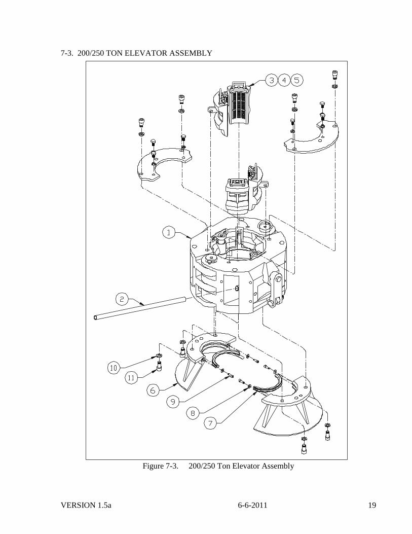
7-3. 200/250 TON ELEVATOR ASSEMBLY
Figure 7-3. 200/250 Ton Elevator Assembly
VERSION 1.5a 6-6-2011 20
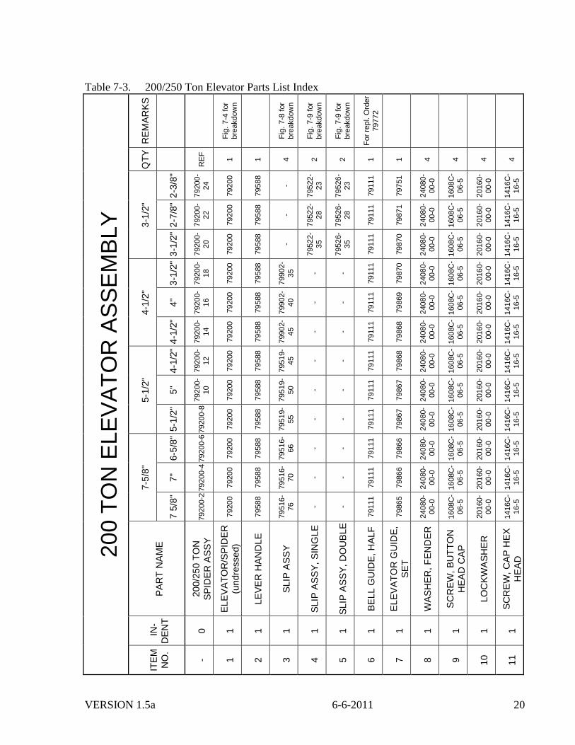
Table 7-3. 200/250 Ton Elevator Parts List Index
200 T
ON
ELE
VA
TO
R A
SS
EM
BLY
RE
MA
RK
S
Fig
. 7-4
for
bre
akdow
n
Fig
. 7-8
for
bre
akdow
n
Fig
. 7-9
for
bre
akdow
n
Fig
. 7-9
for
bre
akdow
n
Fo
r re
pl. O
rder
79772
QT
Y
RE
F
1
1
4
2
2
1
1
4
4
4
4
3-1
/2"
2-3
/8"
79200-
24
79200
79588
-
79522-
23
79526-
23
79111
79751
24080-
00-0
1608C
-
06-5
20160-
00-0
1416C
-
16-5
2-7
/8"
79200-
22
79200
79588
-
79522-
28
79526-
28
79111
79871
24080-
00-0
1608C
-
06-5
20160-
00-0
1416C
-
16-5
3-1
/2"
79200-
20
79200
79588
-
79522-
35
79526-
35
79111
79870
24080-
00-0
1608C
-
06-5
20160-
00-0
1416C
-
16-5
4-1
/2"
3-1
/2"
79200-
18
79200
79588
79902-
35
- -
79111
79870
24080-
00-0
1608C
-
06-5
20160-
00-0
1416C
-
16-5
4"
79200-
16
79200
79588
79902-
40
- -
79111
79869
24080-
00-0
1608C
-
06-5
20160-
00-0
1416C
-
16-5
4-1
/2"
79200-
14
79200
79588
79902-
45
- -
79111
79868
24080-
00-0
1608C
-
06-5
20160-
00-0
1416C
-
16-5
5-1
/2"
4-1
/2"
79200-
12
79200
79588
79519-
45
- -
79111
79868
24080-
00-0
1608C
-
06-5
20160-
00-0
1416C
-
16-5
5"
79200-
10
79200
79588
79519-
50
- -
79111
79867
24080-
00-0
1608C
-
06-5
20160-
00-0
1416C
-
16-5
5-1
/2"
79200-8
79200
79588
79519-
55
- -
79111
79867
24080-
00-0
1608C
-
06-5
20160-
00-0
1416C
-
16-5
7-5
/8"
6-5
/8"
79200-6
79200
79588
79516-
66
- -
79111
79866
24080-
00-0
1608C
-
06-5
20160-
00-0
1416C
-
16-5
7"
79200-4
79200
79588
79516-
70
- -
79111
79866
24080-
00-0
1608C
-
06-5
20160-
00-0
1416C
-
16-5
7 5
/8"
79200-2
79200
79588
79516-
76
- -
79111
79865
24080-
00-0
1608C
-
06-5
20160-
00-0
1416C
-
16-5
PA
RT
NA
ME
200/2
50
TO
N
SP
IDE
R A
SS
Y
EL
EV
AT
OR
/SP
IDE
R
(undre
ssed)
LE
VE
R H
AN
DL
E
SLIP
AS
SY
SLIP
AS
SY
, S
ING
LE
SLIP
AS
SY
, D
OU
BLE
BE
LL G
UID
E, H
ALF
EL
EV
AT
OR
GU
IDE
,
SE
T
WA
SH
ER
, F
EN
DE
R
SC
RE
W,
BU
TT
ON
HE
AD
CA
P
LO
CK
WA
SH
ER
SC
RE
W,
CA
P H
EX
HE
AD
IN
-
DE
NT
0
1
1
1
1
1
1
1
1
1
1
1
ITE
M
NO
.
- 1
2
3
4
5
6
7
8
9
10
11
VERSION 1.5a 6-6-2011 21
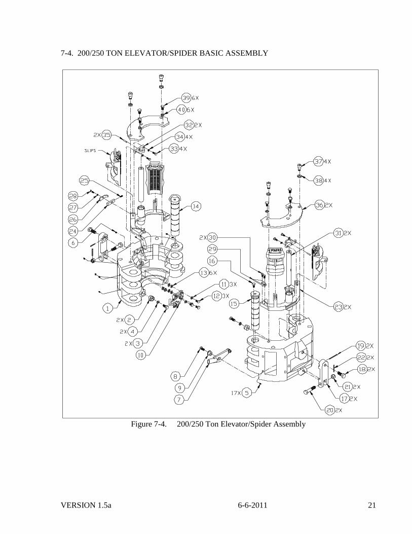
7-4. 200/250 TON ELEVATOR/SPIDER BASIC ASSEMBLY
Figure 7-4. 200/250 Ton Elevator/Spider Assembly
VERSION 1.5a 6-6-2011 22
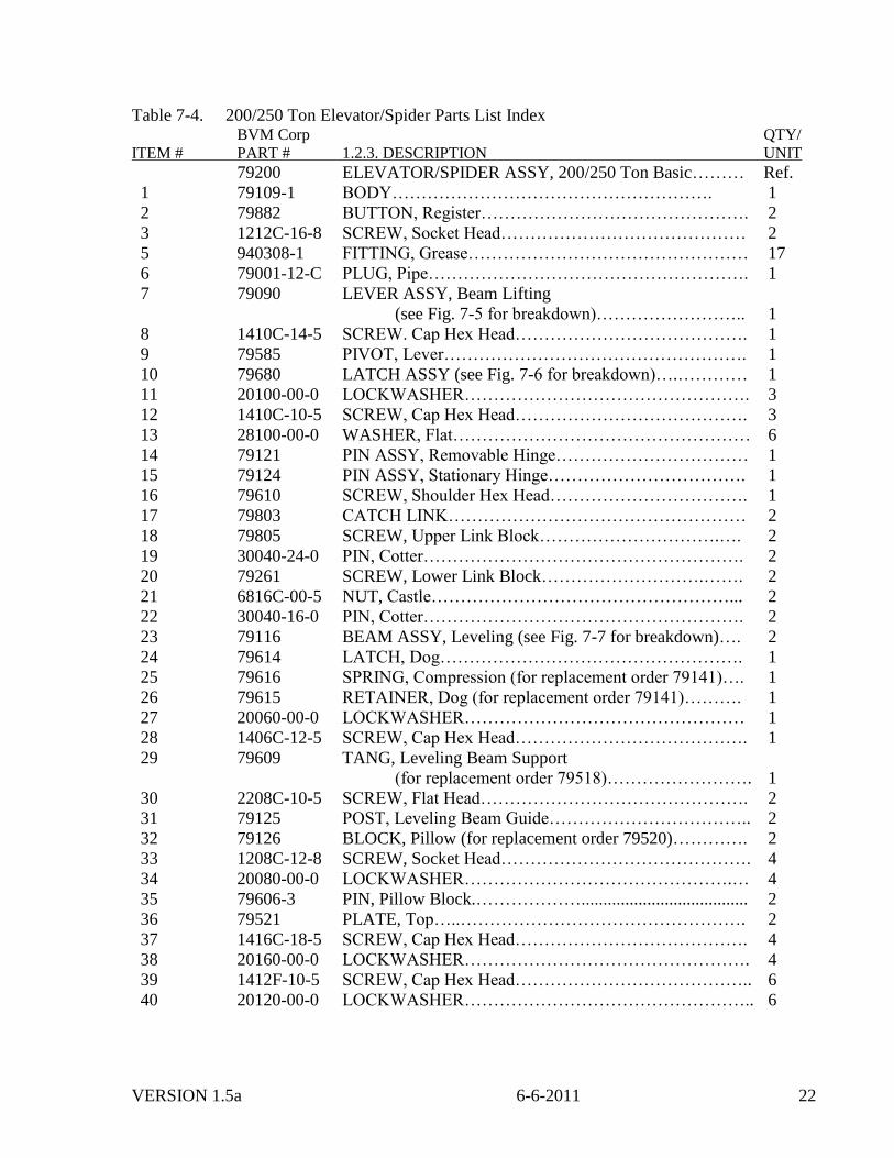
Table 7-4. 200/250 Ton Elevator/Spider Parts List Index BVM Corp QTY/
ITEM # PART # 1.2.3. DESCRIPTION UNIT
79200 ELEVATOR/SPIDER ASSY, 200/250 Ton Basic……… Ref.
1 79109-1 BODY………………………………………………. 1
2 79882 BUTTON, Register………………………………………. 2
3 1212C-16-8 SCREW, Socket Head…………………………………… 2
5 940308-1 FITTING, Grease………………………………………… 17
6 79001-12-C PLUG, Pipe………………………………………………. 1
7 79090 LEVER ASSY, Beam Lifting
(see Fig. 7-5 for breakdown)…………………….. 1
8 1410C-14-5 SCREW. Cap Hex Head…………………………………. 1
9 79585 PIVOT, Lever……………………………………………. 1
10 79680 LATCH ASSY (see Fig. 7-6 for breakdown)….………… 1
11 20100-00-0 LOCKWASHER…………………………………………. 3
12 1410C-10-5 SCREW, Cap Hex Head…………………………………. 3
13 28100-00-0 WASHER, Flat…………………………………………… 6
14 79121 PIN ASSY, Removable Hinge…………………………… 1
15 79124 PIN ASSY, Stationary Hinge……………………………. 1
16 79610 SCREW, Shoulder Hex Head……………………………. 1
17 79803 CATCH LINK…………………………………………… 2
18 79805 SCREW, Upper Link Block………………………….…. 2
19 30040-24-0 PIN, Cotter………………………………………………. 2
20 79261 SCREW, Lower Link Block……………………….……. 2
21 6816C-00-5 NUT, Castle……………………………………………... 2
22 30040-16-0 PIN, Cotter………………………………………………. 2
23 79116 BEAM ASSY, Leveling (see Fig. 7-7 for breakdown)…. 2
24 79614 LATCH, Dog……………………………………………. 1
25 79616 SPRING, Compression (for replacement order 79141)…. 1
26 79615 RETAINER, Dog (for replacement order 79141)………. 1
27 20060-00-0 LOCKWASHER………………………………………… 1
28 1406C-12-5 SCREW, Cap Hex Head…………………………………. 1
29 79609 TANG, Leveling Beam Support
(for replacement order 79518)……………………. 1
30 2208C-10-5 SCREW, Flat Head………………………………………. 2
31 79125 POST, Leveling Beam Guide…………………………….. 2
32 79126 BLOCK, Pillow (for replacement order 79520)…………. 2
33 1208C-12-8 SCREW, Socket Head……………………………………. 4
34 20080-00-0 LOCKWASHER……………………………………….… 4
35 79606-3 PIN, Pillow Block.………………...................................... 2
36 79521 PLATE, Top…..…………………………………………. 2
37 1416C-18-5 SCREW, Cap Hex Head…………………………………. 4
38 20160-00-0 LOCKWASHER…………………………………………. 4
39 1412F-10-5 SCREW, Cap Hex Head………………………………….. 6
40 20120-00-0 LOCKWASHER………………………………………….. 6
VERSION 1.5a 6-6-2011 23
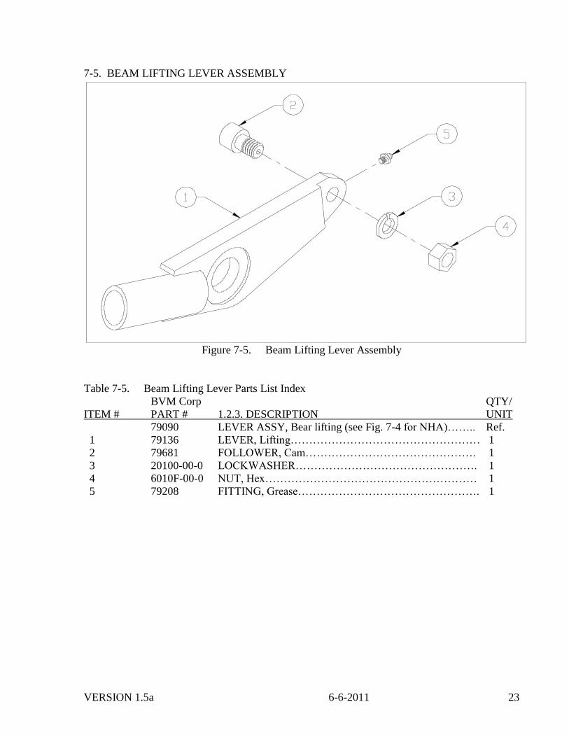
7-5. BEAM LIFTING LEVER ASSEMBLY
Figure 7-5. Beam Lifting Lever Assembly
Table 7-5. Beam Lifting Lever Parts List Index
BVM Corp QTY/
ITEM # PART # 1.2.3. DESCRIPTION UNIT
79090 LEVER ASSY, Bear lifting (see Fig. 7-4 for NHA)…….. Ref.
1 79136 LEVER, Lifting…………………………………………… 1
2 79681 FOLLOWER, Cam………………………………………. 1
3 20100-00-0 LOCKWASHER…………………………………………. 1
4 6010F-00-0 NUT, Hex………………………………………………… 1
5 79208 FITTING, Grease…………………………………………. 1
VERSION 1.5a 6-6-2011 24
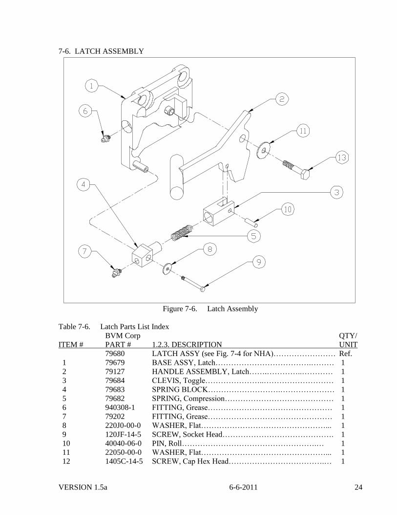
7-6. LATCH ASSEMBLY
Figure 7-6. Latch Assembly
Table 7-6. Latch Parts List Index
BVM Corp QTY/
ITEM # PART # 1.2.3. DESCRIPTION UNIT
79680 LATCH ASSY (see Fig. 7-4 for NHA)…………………… Ref.
1 79679 BASE ASSY, Latch……………………………….……… 1
2 79127 HANDLE ASSEMBLY, Latch…….…………..………… 1
3 79684 CLEVIS, Toggle…………………..……………………… 1
4 79683 SPRING BLOCK……………………….………………… 1
5 79682 SPRING, Compression…………………………………… 1
6 940308-1 FITTING, Grease………………………………………… 1
7 79202 FITTING, Grease………………………………………… 1
8 220J0-00-0 WASHER, Flat…………………………………………... 1
9 120JF-14-5 SCREW, Socket Head……………………………………. 1
10 40040-06-0 PIN, Roll…………………………………………….… 1
11 22050-00-0 WASHER, Flat…………………………………………... 1
12 1405C-14-5 SCREW, Cap Hex Head……………………………….… 1
VERSION 1.5a 6-6-2011 25
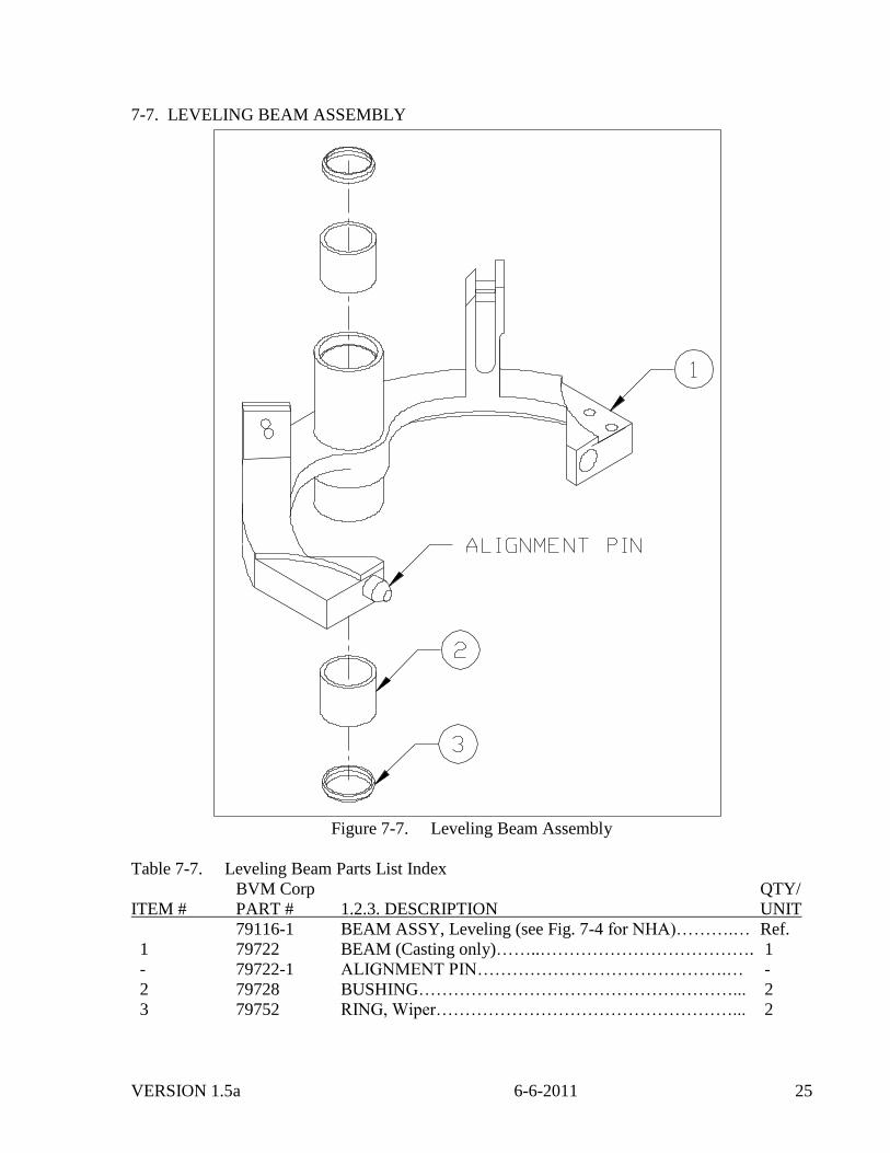
7-7. LEVELING BEAM ASSEMBLY
Figure 7-7. Leveling Beam Assembly
Table 7-7. Leveling Beam Parts List Index
BVM Corp QTY/
ITEM # PART # 1.2.3. DESCRIPTION UNIT
79116-1 BEAM ASSY, Leveling (see Fig. 7-4 for NHA)……….… Ref.
1 79722 BEAM (Casting only)……..………………………………. 1
- 79722-1 ALIGNMENT PIN…………………………………….… -
2 79728 BUSHING………………………………………………... 2
3 79752 RING, Wiper……………………………………………... 2
VERSION 1.5a 6-6-2011 26
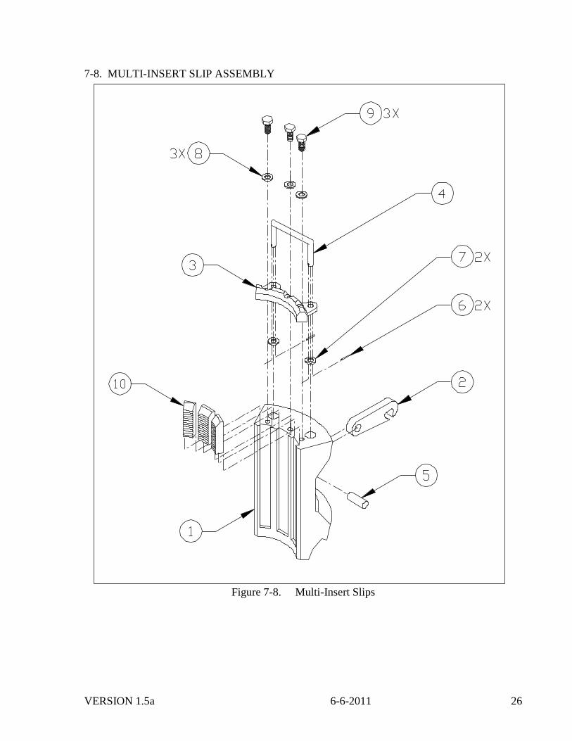
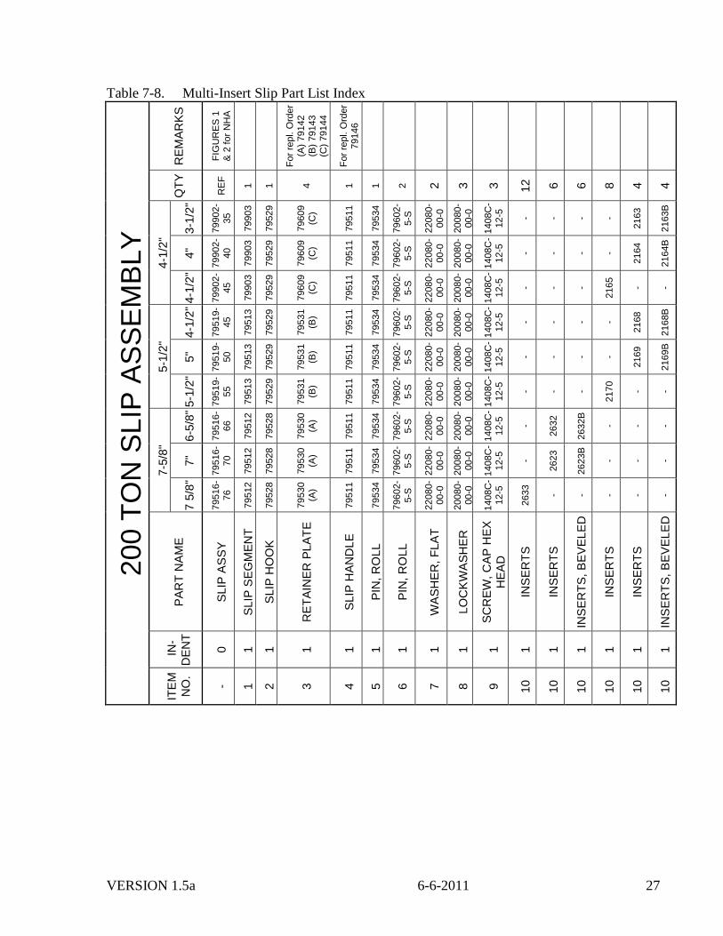
7-8. MULTI-INSERT SLIP ASSEMBLY
Figure 7-8. Multi-Insert Slips
VERSION 1.5a 6-6-2011 27
Table 7-8. Multi-Insert Slip Part List Index
200 T
ON
SLIP
AS
SE
MB
LY
RE
MA
RK
S
FIG
UR
ES
1
& 2
for
NH
A
Fo
r re
pl. O
rder
(A)
79142
(B)
79143
(C)
79144
Fo
r re
pl. O
rder
79146
QT
Y
RE
F
1
1
4
1
1
2
2
3
3
12
6
6
8
4
4
4-1
/2"
3-1
/2"
79902-
35
79903
79529
79609
(C)
79511
79534
79602-
5-S
22080-
00-0
20080-
00-0
1408C
-12-5
- - - -
2163
2163B
4"
79902-
40
79903
79529
79609
(C)
79511
79534
79602-
5-S
22080-
00-0
20080-
00-0
1408C
-12-5
- - - -
2164
2164B
4-1
/2"
79902-
45
79903
79529
79609
(C)
79511
79534
79602-
5-S
22080-
00-0
20080-
00-0
1408C
-12-5
- - -
2165
- -
5-1
/2"
4-1
/2"
79519-
45
79513
79529
79531
(B)
79511
79534
79602-
5-S
22080-
00-0
20080-
00-0
1408C
-12-5
- - - -
2168
2168B
5"
79519-
50
79513
79529
79531
(B)
79511
79534
79602-
5-S
22080-
00-0
20080-
00-0
1408C
-12-5
- - - -
2169
2169B
5-1
/2"
79519-
55
79513
79529
79531
(B)
79511
79534
79602-
5-S
22080-
00-0
20080-
00-0
1408C
-12-5
- - -
2170
- -
7-5
/8"
6-5
/8"
79516-
66
79512
79528
79530
(A)
79511
79534
79602-
5-S
22080-
00-0
20080-
00-0
1408C
-12-5
-
2632
2632B
- - -
7"
79516-
70
79512
79528
79530
(A)
79511
79534
79602-
5-S
22080-
00-0
20080-
00-0
1408C
-12-5
-
2623
2623B
- - -
7 5
/8"
79516-
76
79512
79528
79530
(A)
79511
79534
79602-
5-S
22080-
00-0
20080-
00-0
1408C
-12-5
2633
- - - - -
PA
RT
NA
ME
SLIP
AS
SY
SLIP
SE
GM
EN
T
SLIP
HO
OK
RE
TA
INE
R P
LA
TE
SLIP
HA
ND
LE
PIN
, R
OLL
PIN
, R
OLL
WA
SH
ER
, F
LA
T
LO
CK
WA
SH
ER
SC
RE
W,
CA
P H
EX
HE
AD
INS
ER
TS
INS
ER
TS
INS
ER
TS
, B
EV
EL
ED
INS
ER
TS
INS
ER
TS
INS
ER
TS
, B
EV
EL
ED
IN
-
DE
NT
0
1
1
1
1
1
1
1
1
1
1
1
1
1
1
1
ITE
M
NO
.
- 1
2
3
4
5
6
7
8
9
10
10
10
10
10
10
VERSION 1.5a 6-6-2011 28
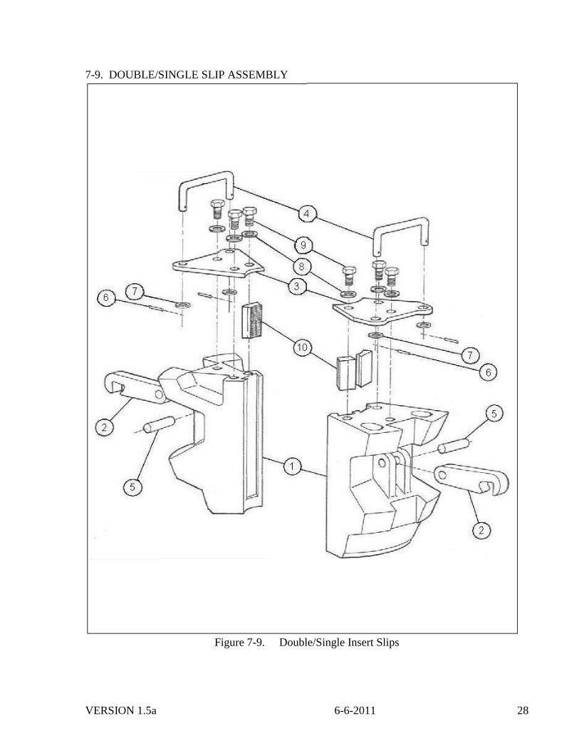
7-9. DOUBLE/SINGLE SLIP ASSEMBLY
Figure 7-9. Double/Single Insert Slips
VERSION 1.5a 6-6-2011 29
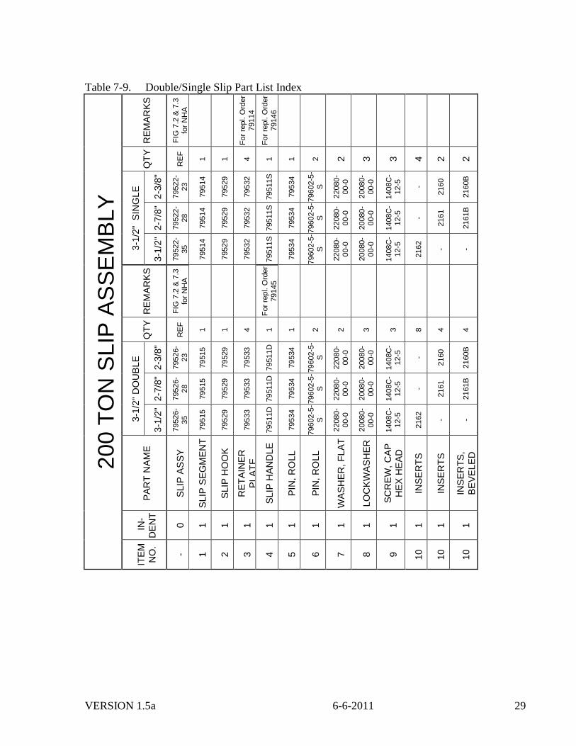
Table 7-9. Double/Single Slip Part List Index
200 T
ON
SLIP
AS
SE
MB
LY
RE
MA
RK
S
FIG
7.2
& 7
.3
for
NH
A
Fo
r re
pl. O
rder
79114
Fo
r re
pl. O
rder
79146
QT
Y
RE
F
1
1
4
1
1
2
2
3
3
4
2
2
3-1
/2"
SIN
GL
E
2-3
/8"
79522-
23
79514
79529
79532
79511S
79534
79602-5
-
S
22080-
00-0
20080-
00-0
1408C
-12-5
-
2160
2160B
2-7
/8"
79522-
28
79514
79529
79532
79511S
79534
79602-5
-
S
22080-
00-0
20080-
00-0
1408C
-12-5
-
2161
2161B
3-1
/2"
79522-
35
79514
79529
79532
79511S
79534
79602-5
-
S
22080-
00-0
20080-
00-0
1408C
-12-5
2162
- -
RE
MA
RK
S
FIG
7.2
& 7
.3
for
NH
A
Fo
r re
pl. O
rder
79145
QT
Y
RE
F
1
1
4
1
1
2
2
3
3
8
4
4
3-1
/2"
DO
UB
LE
2-3
/8"
79526-
23
79515
79529
79533
79511D
79534
79602-5
-
S
22080-
00-0
20080-
00-0
1408C
-12-5
-
2160
2160B
2-7
/8"
79526-
28
79515
79529
79533
79511D
79534
79602-5
-
S
22080-
00-0
20080-
00-0
1408C
-12-5
-
2161
2161B
3-1
/2"
79526-
35
79515
79529
79533
79511D
79534
79602-5
-
S
22080-
00-0
20080-
00-0
1408C
-12-5
2162
- -
PA
RT
NA
ME
SLIP
AS
SY
SLIP
SE
GM
EN
T
SLIP
HO
OK
RE
TA
INE
R
PL
AT
E
SLIP
HA
ND
LE
PIN
, R
OLL
PIN
, R
OLL
WA
SH
ER
, F
LA
T
LO
CK
WA
SH
ER
SC
RE
W,
CA
P
HE
X H
EA
D
INS
ER
TS
INS
ER
TS
INS
ER
TS
,
BE
VE
LE
D
IN
-
DE
NT
0
1
1
1
1
1
1
1
1
1
1
1
1
ITE
M
NO
.
- 1
2
3
4
5
6
7
8
9
10
10
10
VERSION 1.5a 6-6-2011 30
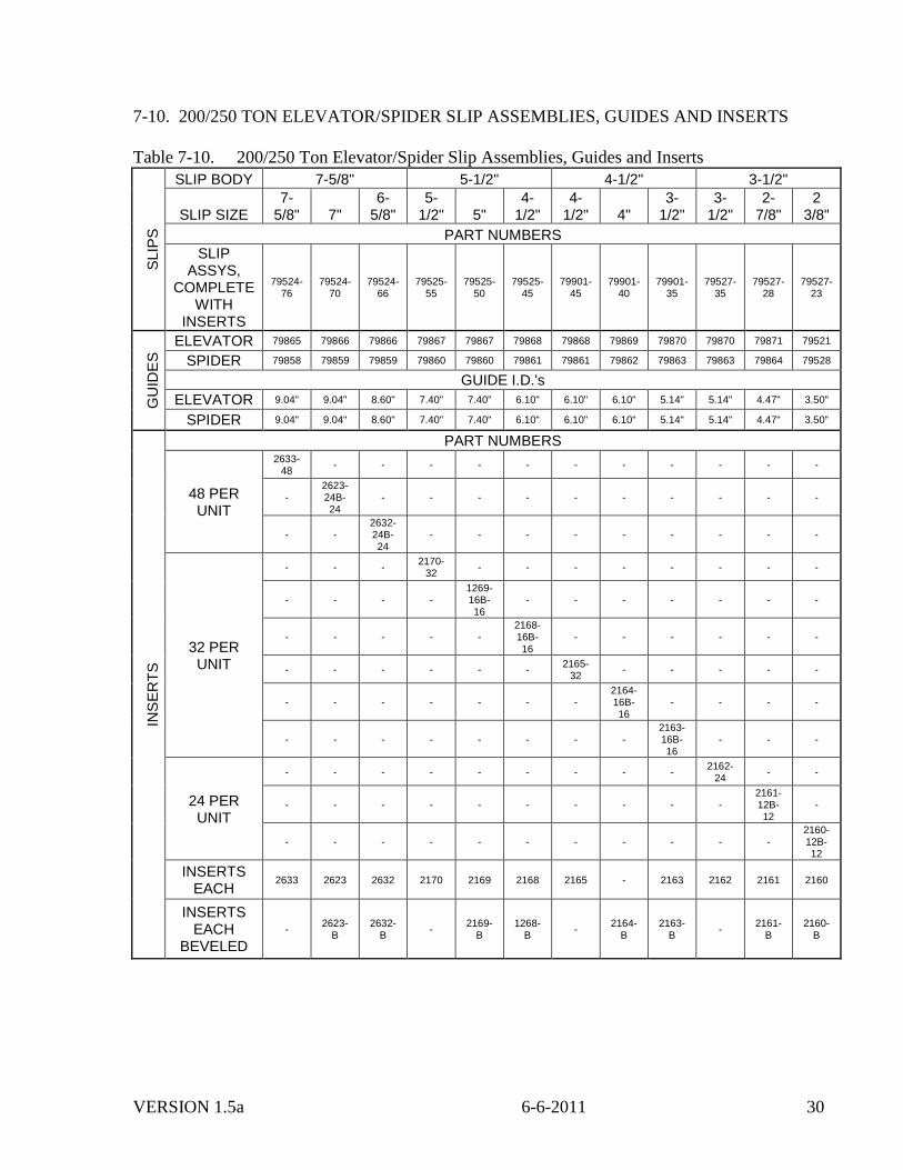
7-10. 200/250 TON ELEVATOR/SPIDER SLIP ASSEMBLIES, GUIDES AND INSERTS
Table 7-10. 200/250 Ton Elevator/Spider Slip Assemblies, Guides and Inserts S
LIP
S
SLIP BODY 7-5/8" 5-1/2" 4-1/2" 3-1/2"
SLIP SIZE 7-
5/8" 7" 6-
5/8" 5-
1/2" 5" 4-
1/2" 4-
1/2" 4" 3-
1/2" 3-
1/2" 2-
7/8" 2
3/8"
PART NUMBERS
SLIP ASSYS,
COMPLETE WITH
INSERTS
79524-76
79524-70
79524-66
79525-55
79525-50
79525-45
79901-45
79901-40
79901-35
79527-35
79527-28
79527-23
GU
IDE
S ELEVATOR 79865 79866 79866 79867 79867 79868 79868 79869 79870 79870 79871 79521
SPIDER 79858 79859 79859 79860 79860 79861 79861 79862 79863 79863 79864 79528
GUIDE I.D.'s
ELEVATOR 9.04" 9.04" 8.60" 7.40" 7.40" 6.10" 6.10" 6.10" 5.14" 5.14" 4.47" 3.50"
SPIDER 9.04" 9.04" 8.60" 7.40" 7.40" 6.10" 6.10" 6.10" 5.14" 5.14" 4.47" 3.50"
INS
ER
TS
PART NUMBERS
48 PER UNIT
2633-48
- - - - - - - - - - -
- 2623-24B-24
- - - - - - - - - -
- - 2632-24B-24
- - - - - - - - -
32 PER UNIT
- - - 2170-
32 - - - - - - - -
- - - - 1269-16B-16
- - - - - - -
- - - - - 2168-16B-16
- - - - - -
- - - - - - 2165-
32 - - - - -
- - - - - - - 2164-16B-16
- - - -
- - - - - - - - 2163-16B-16
- - -
24 PER UNIT
- - - - - - - - - 2162-
24 - -
- - - - - - - - - - 2161-12B-12
-
- - - - - - - - - - - 2160-12B-12
INSERTS EACH
2633 2623 2632 2170 2169 2168 2165 - 2163 2162 2161 2160
INSERTS EACH
BEVELED
- 2623-
B 2632-
B -
2169-B
1268-B
- 2164-
B 2163-
B -
2161-B
2160-B
VERSION 1.5a 6-6-2011 31
7-11. 200/250 TON ELEVATOR/SPIDER ACCESSORIES
Table 7-11. 200/250 Ton Elevator/Spider Accessories
BVM Corp QTY/
ITEM # PART # 1.2.3. DESCRIPTION UNIT
1 79588 LEVER HANDLE……………………………….……..… 1
2 79772 BELL GUIDE………………………………..…………… 1
3 79105 FOOT PEDAL………………………………………….… 1
4 79462 ADAPTER PLATE..…………………………….……..… 1
7-12. 200/250 TON ELEVATOR/SPIDER FOREIGN SPARE PARTS
Table 7-12. 200/250 Ton Elevator/Spider Foreign Spare Parts
BVM Corp QTY/
ITEM # PART # 1.2.3. DESCRIPTION UNIT
79147 One Years Foreign Spare Parts Kit (less inserts) for
200/250 Ton Elevator/Spider Unit.*………………. 1
1 79751 RING, Wiper……………………………………………... 4
2 79805 SCREW, Cap Modified……………………………….…. 2
3 79261 SCREW, Cap Modified……………………………….…. 2
4 79534 PIN, Spring……………………………………………….. 4
5 79588 HANDLE, Lever…………………………………………. 1
6 79614 LATCH, Dog……………………………………….…..… 1
7 79680 LATCH ASSEMBLY……………………………………. 1
8 79681 FOLLOWER, CAM…………………………………..…. 1
9 79141 LATCH RETAINER KIT……………………………….. 1
10 79146 HANDLE SLIP LIFTING KIT………………………….. 4
11 1406C-12-5 CAPSCREW, Hex Head, 3/8 – 16 UNC X 1/2………….. 4
12 1408C-12-5 CAPSCREW, Hex Head, 1/2 – 13 UNC X 2-1/4……….. 12
13 1408C-12-5 CAPSCREW, Hex Head, 1/2 – 13 UNC X 1-1/2…….…. 4
14 1410C-10-5 CAPSCREW, Hex Head, 5/8 – 11 UNC X 1-1/4……..…. 3
15 1416C-14-5 CAPSCREW, Hex Head, 1 – 8 UNC X 2-1/4……………. 4
16 6416C-00-0 NUT, Hex-Slotted, 1” UNC…………………………….... 2
17 2208C-10-5 CAPSCREW, Flat Head, 1/2 – 13 UNC X 1 1/4..…….…. 2
18 20080-00-0 LOCKWASHER, 1/2”……………………………………. 16
19 20100-00-0 LOCKWASHER, 5/8’…………………………………..... 3
20 20160-00-0 LOCKWASHER, 1”……………………………………… 4
21 30030-24-0 COTTER PIN, 3/16 X 2……..………………………….... 2
22 30030-16-0 COTTER PIN, 3/16 X 2………………………………….. 2
23 79201 FITTING, Grease………………………………………… 17
24 601000-0 NUT, Hex Standard, 5/8” UNF…………………………... 1
* Recommended Spares include one set of inserts for each size of casing used per unit
VERSION 1.5a 6-6-2011 32
200/250 Ton Spider Elevator Pneumatic
VERSION 1.5a 6-6-2011 33
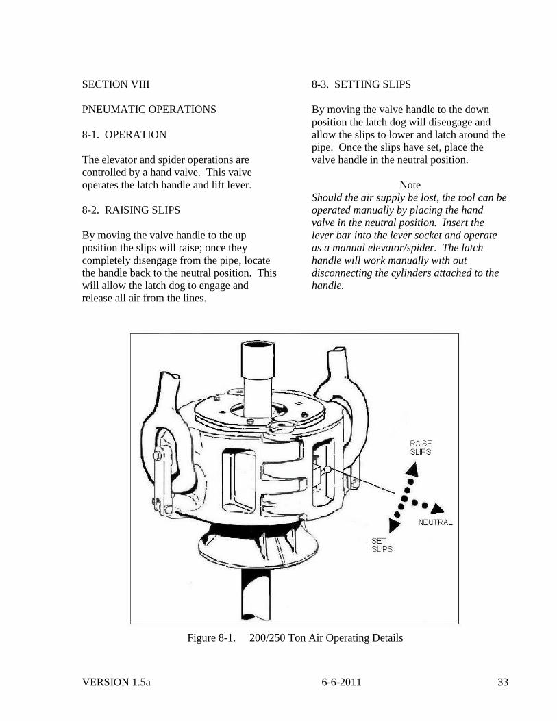
SECTION VIII
PNEUMATIC OPERATIONS
8-1. OPERATION
The elevator and spider operations are
controlled by a hand valve. This valve
operates the latch handle and lift lever.
8-2. RAISING SLIPS
By moving the valve handle to the up
position the slips will raise; once they
completely disengage from the pipe, locate
the handle back to the neutral position. This
will allow the latch dog to engage and
release all air from the lines.
8-3. SETTING SLIPS
By moving the valve handle to the down
position the latch dog will disengage and
allow the slips to lower and latch around the
pipe. Once the slips have set, place the
valve handle in the neutral position.
Note
Should the air supply be lost, the tool can be
operated manually by placing the hand
valve in the neutral position. Insert the
lever bar into the lever socket and operate
as a manual elevator/spider. The latch
handle will work manually with out
disconnecting the cylinders attached to the
handle.
Figure 8-1. 200/250 Ton Air Operating Details
VERSION 1.5a 6-6-2011 34
8-4. AIR OPERATING PARTS LIST
The parts lists in this section reflect part
numbers and quantities used in the 200/250
TonAir Operating Elevator/Spider. The
quantity per unit column is the total number
of parts for the 200/250 Ton Air Operating
Elevator/Spider.
The parts list uses the indention method to
show component subassembly relationships.
Items listed one column to the right under
assembly is detailed parts of that assembly.
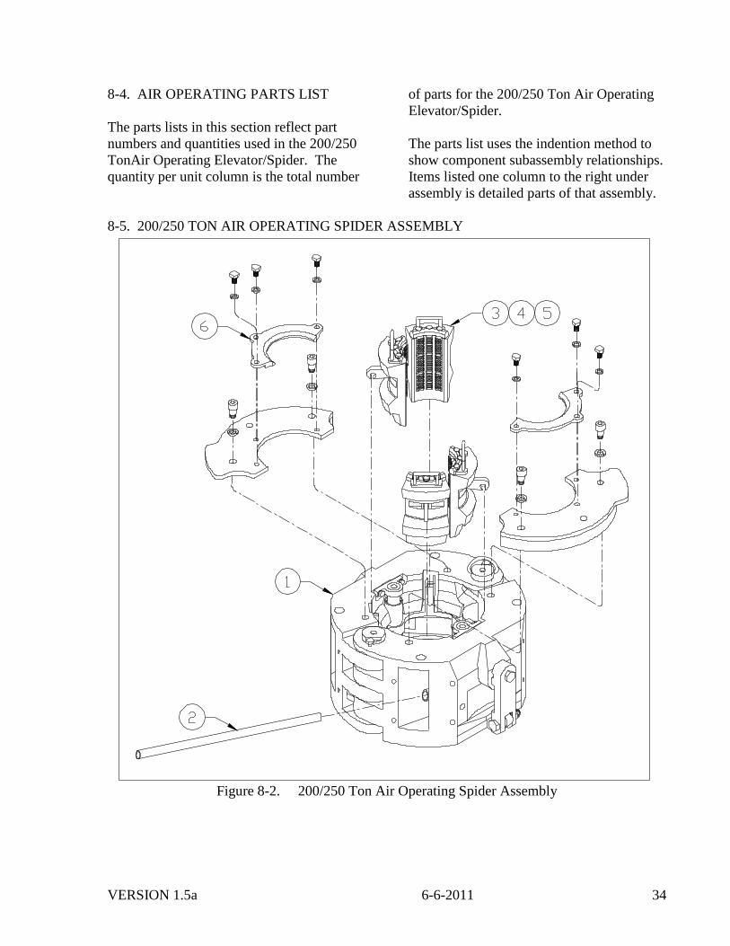
8-5. 200/250 TON AIR OPERATING SPIDER ASSEMBLY
Figure 8-2. 200/250 Ton Air Operating Spider Assembly
VERSION 1.5a 6-6-2011 35
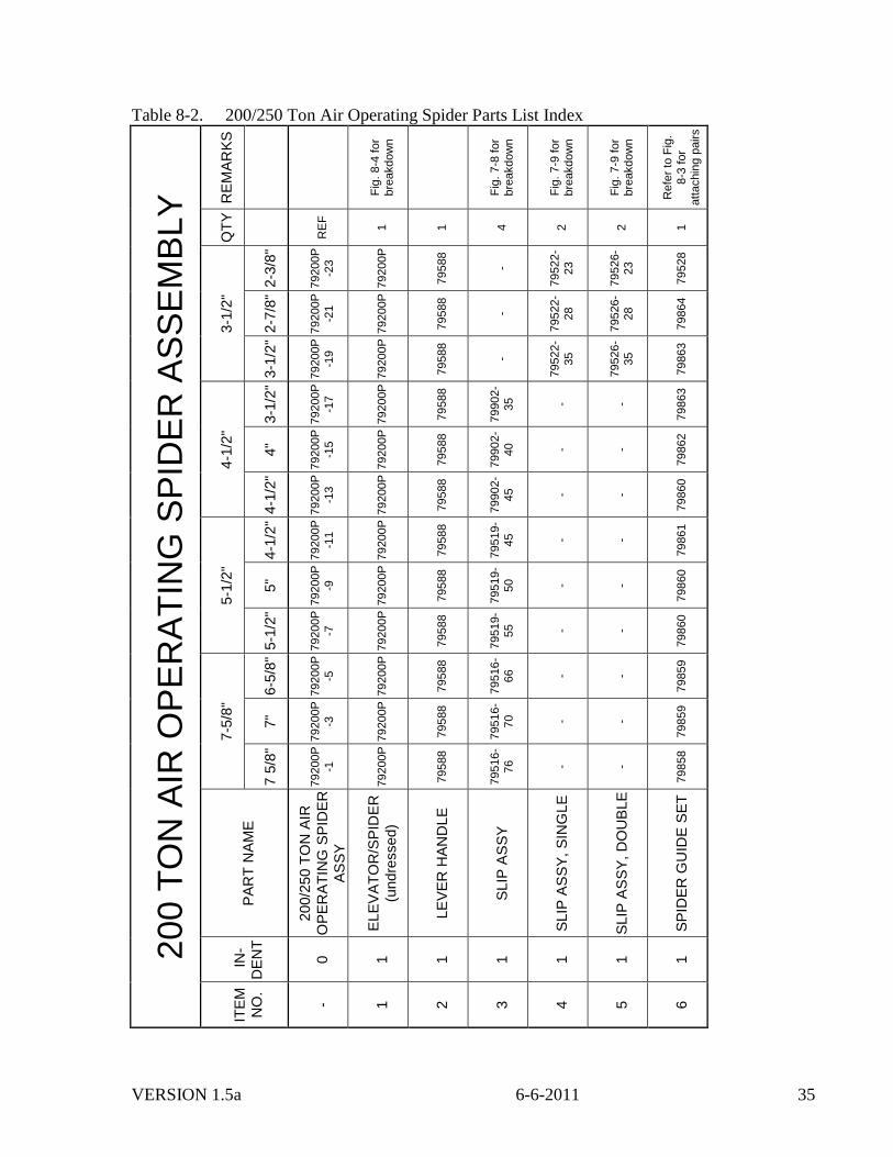
Table 8-2. 200/250 Ton Air Operating Spider Parts List Index
200 T
ON
AIR
OP
ER
AT
ING
SP
IDE
R A
SS
EM
BLY
RE
MA
RK
S
Fig
. 8-4
for
bre
akdow
n
Fig
. 7-8
for
bre
akdow
n
Fig
. 7-9
for
bre
akdow
n
Fig
. 7-9
for
bre
akdow
n
Refe
r to
Fig
.
8-3
for
att
achin
g p
airs
QT
Y
RE
F
1
1
4
2
2
1
3-1
/2"
2-3
/8"
79200P
-23
79200P
79588
-
79522-
23
79526-
23
79528
2-7
/8"
79200P
-21
79200P
79588
-
79522-
28
79526-
28
79864
3-1
/2"
79200P
-19
79200P
79588
-
79522-
35
79526-
35
79863
4-1
/2"
3-1
/2"
79200P
-17
79200P
79588
79902-
35
- -
79863
4"
79200P
-15
79200P
79588
79902-
40
- -
79862
4-1
/2"
79200P
-13
79200P
79588
79902-
45
- -
79860
5-1
/2"
4-1
/2"
79200P
-11
79200P
79588
79519-
45
- -
79861
5"
79200P
-9
79200P
79588
79519-
50
- -
79860
5-1
/2"
79200P
-7
79200P
79588
79519-
55
- -
79860
7-5
/8"
6-5
/8"
79200P
-5
79200P
79588
79516-
66
- -
79859
7"
79200P
-3
79200P
79588
79516-
70
- -
79859
7 5
/8"
79200P
-1
79200P
79588
79516-
76
- -
79858
PA
RT
NA
ME
200/2
50
TO
N A
IR
OP
ER
AT
ING
SP
IDE
R
AS
SY
EL
EV
AT
OR
/SP
IDE
R
(undre
ssed)
LE
VE
R H
AN
DL
E
SLIP
AS
SY
SLIP
AS
SY
, S
ING
LE
SLIP
AS
SY
, D
OU
BLE
SP
IDE
R G
UID
E S
ET
IN
-
DE
NT
0
1
1
1
1
1
1
ITE
M
NO
.
- 1
2
3
4
5
6
VERSION 1.5a 6-6-2011 36
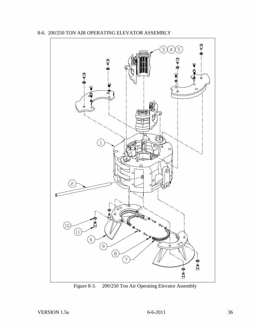
8-6. 200/250 TON AIR OPERATING ELEVATOR ASSEMBLY
Figure 8-3. 200/250 Ton Air Operating Elevator Assembly
VERSION 1.5a 6-6-2011 37
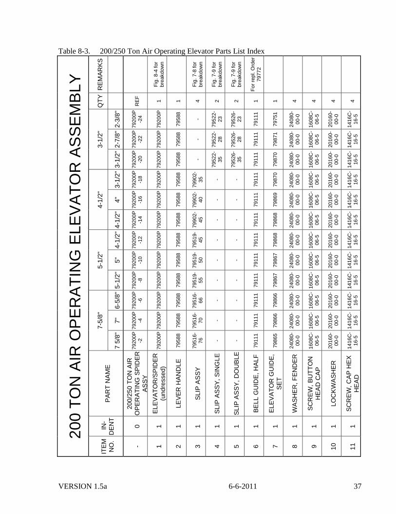
Table 8-3. 200/250 Ton Air Operating Elevator Parts List Index
200 T
ON
AIR
OP
ER
AT
ING
ELE
VA
TO
R A
SS
EM
BLY
RE
MA
RK
S
Fig
. 8-4
for
bre
akdow
n
Fig
. 7-8
for
bre
akdow
n
Fig
. 7-9
for
bre
akdow
n
Fig
. 7-9
for
bre
akdow
n
Fo
r re
pl. O
rder
79772
QT
Y
RE
F
1
1
4
2
2
1
1
4
4
4
4
3-1
/2"
2-3
/8"
79200P
-2
4
79200P
79588
-
79522-
23
79526-
23
79111
79751
24080-
00-0
1608C
-
06-5
20160-
00-0
1416C
-
16-5
2-7
/8"
79200P
-2
2
79200P
79588
-
79522-
28
79526-
28
79111
79871
24080-
00-0
1608C
-
06-5
20160-
00-0
1416C
-
16-5
3-1
/2"
79200P
-2
0
79200P
79588
-
79522-
35
79526-
35
79111
79870
24080-
00-0
1608C
-
06-5
20160-
00-0
1416C
-
16-5
4-1
/2"
3-1
/2"
79200P
-1
8
79200P
79588
79902-
35
- -
79111
79870
24080-
00-0
1608C
-
06-5
20160-
00-0
1416C
-
16-5
4"
79200P
-1
6
79200P
79588
79902-
40
- -
79111
79869
24080-
00-0
1608C
-
06-5
20160-
00-0
1416C
-
16-5
4-1
/2"
79200P
-1
4
79200P
79588
79902-
45
- -
79111
79868
24080-
00-0
1608C
-
06-5
20160-
00-0
1416C
-
16-5
5-1
/2"
4-1
/2"
79200P
-1
2
79200P
79588
79519-
45
- -
79111
79868
24080-
00-0
1608C
-
06-5
20160-
00-0
1416C
-
16-5
5"
79200P
-1
0
79200P
79588
79519-
50
- -
79111
79867
24080-
00-0
1608C
-
06-5
20160-
00-0
1416C
-
16-5
5-1
/2"
79200P
-8
79200P
79588
79519-
55
- -
79111
79867
24080-
00-0
1608C
-
06-5
20160-
00-0
1416C
-
16-5
7-5
/8"
6-5
/8"
79200P
-6
79200P
79588
79516-
66
- -
79111
79866
24080-
00-0
1608C
-
06-5
20160-
00-0
1416C
-
16-5
7"
79200P
-4
79200P
79588
79516-
70
- -
79111
79866
24080-
00-0
1608C
-
06-5
20160-
00-0
1416C
-
16-5
7 5
/8"
79200P
-2
79200P
79588
79516-
76
- -
79111
79865
24080-
00-0
1608C
-
06-5
20160-
00-0
1416C
-
16-5
PA
RT
NA
ME
200/2
50
TO
N A
IR
OP
ER
AT
ING
SP
IDE
R
AS
SY
EL
EV
AT
OR
/SP
IDE
R
(undre
ssed)
LE
VE
R H
AN
DL
E
SLIP
AS
SY
SLIP
AS
SY
, S
ING
LE
SLIP
AS
SY
, D
OU
BLE
BE
LL G
UID
E, H
ALF
EL
EV
AT
OR
GU
IDE
,
SE
T
WA
SH
ER
, F
EN
DE
R
SC
RE
W,
BU
TT
ON
HE
AD
CA
P
LO
CK
WA
SH
ER
SC
RE
W,
CA
P H
EX
HE
AD
IN
-
DE
NT
0
1
1
1
1
1
1
1
1
1
1
1
ITE
M
NO
.
- 1
2
3
4
5
6
7
8
9
10
11
VERSION 1.5a 6-6-2011 38
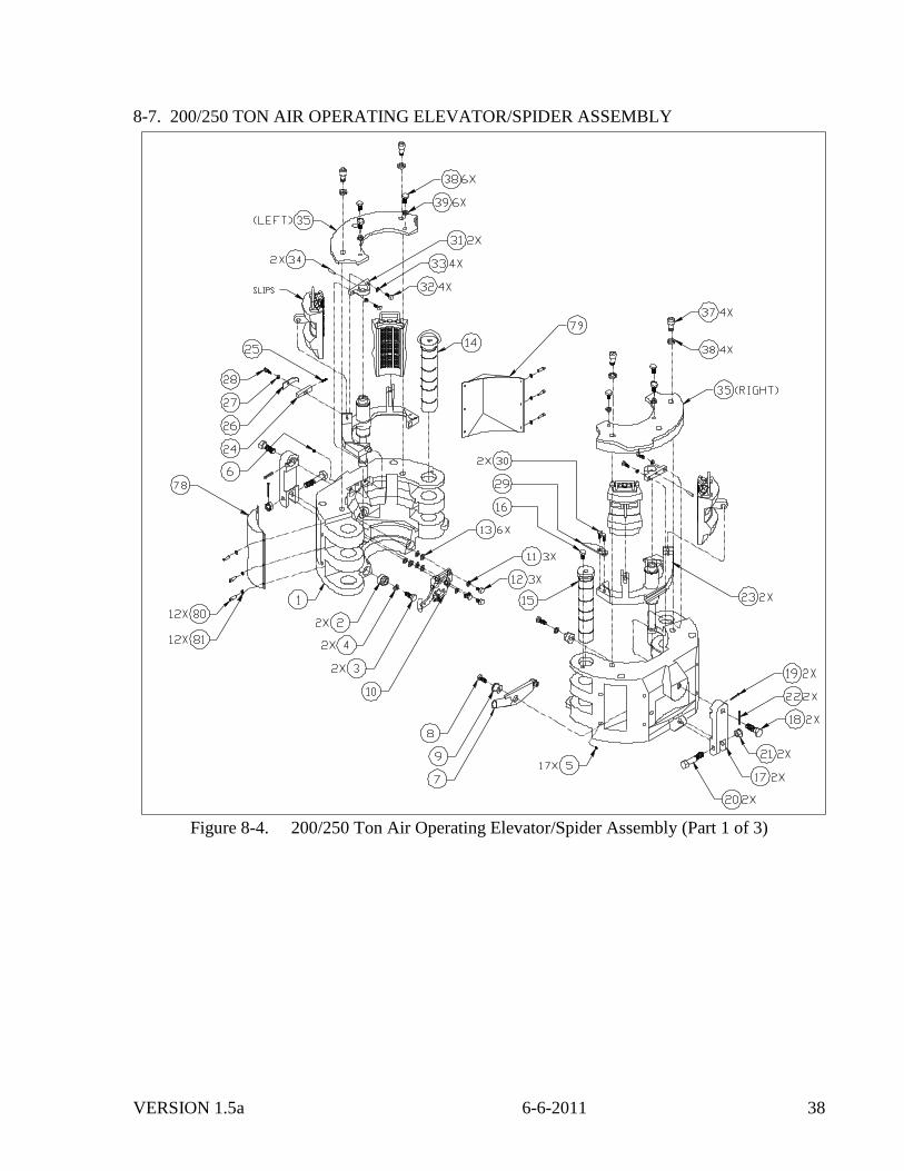
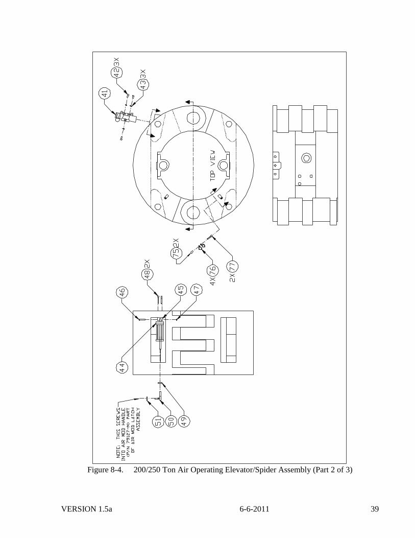
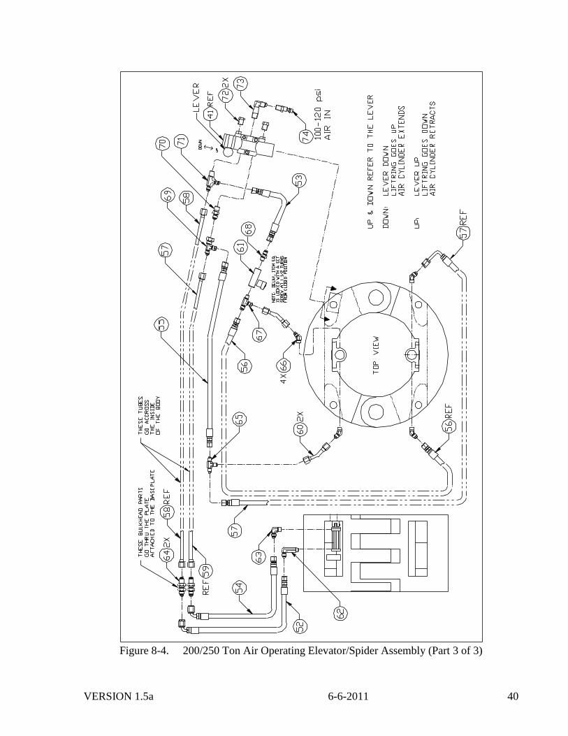
8-7. 200/250 TON AIR OPERATING ELEVATOR/SPIDER ASSEMBLY
Figure 8-4. 200/250 Ton Air Operating Elevator/Spider Assembly (Part 1 of 3)
VERSION 1.5a 6-6-2011 39
Figure 8-4. 200/250 Ton Air Operating Elevator/Spider Assembly (Part 2 of 3)
VERSION 1.5a 6-6-2011 40
Figure 8-4. 200/250 Ton Air Operating Elevator/Spider Assembly (Part 3 of 3)

VERSION 1.5a 6-6-2011 41
Table 8-4. 200/250 Ton Air Operating Elevator/Spider Parts List Index BVM Corp QTY/
ITEM # PART # 1.2.3. DESCRIPTION UNIT
79200P ELEVATOR/SPIDER ASSY, 200/250 Ton Air Operating. Ref.
1 79109M BODY…………………………………………………….. 1
2 79882 BUTTON, Register………………………………………. 2
3 1212C-16-8 SCREW, Socket Head……………………………………. 2
5 940308-1 FITTING, Grease………………………………………… 17
6 79001-12-C PLUG, Pipe………………………………………………. 1
7 79090 LEVER ASSY, Beam Lifting
(see Fig. 7-5 for breakdown)…………………….. 1
8 1410C-14-5 SCREW. Cap Hex Head…………………………………. 1
9 79585 PIVOT, Lever……………………………………………. 1
10 79680M LATCH ASSY, Air Operating (see Fig. 8-5 for
breakdown)…………………………………….… 1
11 20100-00-0 LOCKWASHER…………………………………………. 3
12 1410C-14-5 SCREW, Cap Hex Head…………………………………. 3
13 22100-00-0 WAHSER, Flat…………………………………………… 6
14 79120 PIN ASSY, Removable Hinge…………………………… 1
15 79120 PIN ASSY, Stationary Hinge……………………………. 1
16 79610 SCREW, Shoulder Hex Head……………………………. 1
17 79803 CATCH LINK…………………………………………… 2
18 79805 SCREW, Upper Link Block…..…………………………. 2
19 30030-32-0 PIN, Cotter………………………….……………………. 2
20 79261 SCREW, Lower Link Block….…….……………………. 2
21 6816C-00-5 NUT, Castle…….………………………………………... 2
22 30030-24-0 PIN, Cotter………………………………………………. 2
23 79116M BEAM ASSY, Air Operating Leveling (see Fig. 8-6
for breakdown)………………………………….. 2
24 79614M LATCH, Dog Modified…………………………………. 1
25 79616 SPRING, Compression (for replacement order 79141)…. 1
26 79615 RETAINER, Dog (for replacement order 79141)………. 1
27 20060-00-0 LOCKWASHER………………………………………… 1
28 1406C-12-5 SCREW, Cap Hex Head…………………………………. 1
29 79609 TANG, Leveling Beam Support
(for replacement order 79518)……………………. 1
30 1008C-08-0 SCREW, Flat Head………………………………………. 2
31 79126 BLOCK, Pillow (for replacement order 79520)…………. 2
32 1208C-12-8 SCREW, Socket Head……………………………………. 4
33 20080-00-0 LOCKWASHER……………………………………….… 4
34 79606-3 PIN, Pillow Block.………………...................................... 2
35 10422 RETAINER ASSEMBLY, Air Operated Top……………. 1
36 ----- NOT USED
37 1416C-32-5 SCREW, Cap Hex Head…………………………………. 4
38 20160-00-0 LOCKWASHER…………………………………………. 4
39 1412F-10-5 SCREW, Cap Hex Head………………………………….. 6
40 20120-00-0 LOCKWASHER………………………………………….. 6
VERSION 1.5a 6-6-2011 42
41 79930 VALVE, Beam Air Actuator…………………………….. 1
42 1204F-12-5 SCREW, Socket Head Cap..………………………….….. 3
43 20040-00-0 LOCKWASHER…………………………………………. 3
44 79933 CYLINDER, Latch…………………………………….... 1
45 10442 BRACKET, Air Cylinder…………………………….….. 1
46 120JF-14-8 SCREW………………………………………………..… 1
47 620JF-00-0 LOCKNUT.…………………………………………….... 1
48 1204C-24-8 SCREW, Socket Head Cap …………………………….... 2
49 6005F-00-0 NUT, Hex………………………………………………… 1
50 79937 LINKAGE ROD ENDS…………………………………. 1
51 6205F-00-0 LOCKNUT………………………………………………. 1
52 10435 HOSE, Retract…..……………………………………….. 1
53 10436 HOSE, Main Beam Lower…………….………………… 1
54 10437 HOSE, Extend…..……………………………………….. 1
55 10438 HOSE, Main Beam Lift…..………….………………….. 1
56 10439 HOSE, Farside Beam Lower…………………………….. 1
57 10440 HOSE, Farside Beam Lift……………………………….. 1
58 10444 TUBE, Air Cylinder Retract…………………….…..…... 1
59 10445 TUBE, Air Cylinder Extend….………………………….. 1
60 10446 TUBE, Lift Cylinder Extension……………………...….. 1
61 BPF200B DELAY………………………………………………….. 1
62 B4-CCCTX-S ELBOW, Extra Long Male……………………….……… 1
63 B4-CTX-S ELBOW, Male…………………………………………... 1
64 B4-WTX-S UNION, Bulkhead….………………………………..…... 2
65 B4-JTX-S TEE, Union………………………………………..…….. 1
66 B4-VTX-S ELBOW, 45 Deg Male……………………………..……. 4
67 B4-RTX-S TEE, Male Run………………………………………...... 1
68 B4-FTX-S CONNECTOR, Male……………………………………. 1
69 B4-R6X-S TEE, Swivel Nut Run……………………………………. 1
70 B4-4-FTX-S CONNECTOR, Male…….……………………..……..…. 1
71 B4-4-4-RTX-S TEE, Male Run………………………………………… 1
72 BBV2 VENT, ¼” Breather……………………………………… 2
73 B1/4 CR-S ELBOW, Male Pipe……………………………………… 1
74 BH3C FPT 2/30 Series……………………………………….…. 1
75 10447 RAISER, Clamp…………………………………………. 1
76 10448 CLAMP..…………………………………………............ 4
77 1204C-10-8 SCREW, Socket Head Cap……………………………… 2
78 10431 METAL GUARD, Rounded…………………………….. 1
79 10432 METAL GUARD, Triangle……………………….…….. 1
80 1206C-06-8 SCREW, Socket Head Cap……………………………… 12
81 20060-00-0 LOCKWASHER……………………………………….... 12
VERSION 1.5a 6-6-2011 43
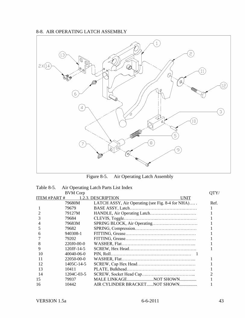
8-8. AIR OPERATING LATCH ASSEMBLY
Figure 8-5. Air Operating Latch Assembly
Table 8-5. Air Operating Latch Parts List Index BVM Corp QTY/
ITEM # PART # 1.2.3. DESCRIPTION UNIT
79680M LATCH ASSY, Air Operating (see Fig. 8-4 for NHA)…. . Ref.
1 79679 BASE ASSY, Latch……………………………….……… 1
2 79127M HANDLE, Air Operating Latch……………………..…… 1
3 79684 CLEVIS, Toggle…………………..……………………… 1
4 79683M SPRING BLOCK, Air Operating……….………………… 1
5 79682 SPRING, Compression…………………………………… 1
6 940308-1 FITTING, Grease………………………………………… 1
7 79202 FITTING, Grease………………………………………… 1
8 220J0-00-0 WASHER, Flat…………………………………………... 1
9 120JF-14-5 SCREW, Hex Head………………………………………. 1
10 40040-06-0 PIN, Roll…………………………………………….… 1
11 22050-00-0 WASHER, Flat…………………………………………... 1
12 1405C-14-5 SCREW, Cap Hex Head……………………………….… 1
13 10411 PLATE, Bulkhead……………………………………….. 1
14 1204C-03-5 SCREW, Socket Head Cap….…………………………... 2
15 79937 MALE LINKAGE........................NOT SHOWN............... 1
16 10442 AIR CYLINDER BRACKET......NOT SHOWN................ 1
VERSION 1.5a 6-6-2011 44
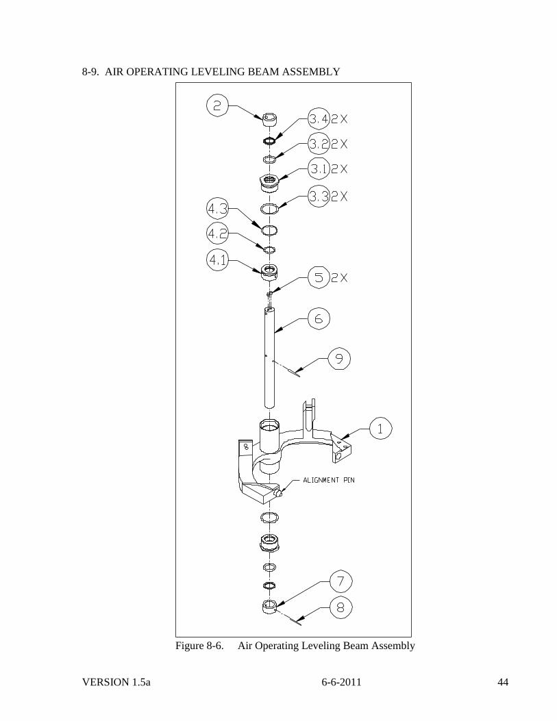
8-9. AIR OPERATING LEVELING BEAM ASSEMBLY
Figure 8-6. Air Operating Leveling Beam Assembly
VERSION 1.5a 6-6-2011 45
Table 8-6. Air Operating Leveling Beam Parts List Index
BVM Corp QTY/
ITEM # PART # 1.2.3. DESCRIPTION UNIT
79116M BEAM ASSEMBLY, Air Operating Leveling (see
Fig. 8-4 for NHA)…………………………………. Ref.
1 79722M BEAM ASSEMBLY, Air Operating ……..……………… 1
- 79722-1 ALIGNMENT PIN………………………………………. -
2 10423 BUSHING TOP…………………………………………... 1
3 10416 GLAND ASSEMBLY……………………………………. 2
3.1 10413 GLAND…………………………………………………... -
3.2 B51300-325-B SEAL, O-Ring……………………………….…………. -
3.3 B51300-329-B SEAL, O-Ring………..………………………..……….. -
3.4 B940-15 RING, Wiper………………………………….……….…. -
4 10417 PISTON ASSEMBLY……………………………….…… 1
4.1 10414 PISTON…………………………………………..……… -
4.2 B51300-220-B SEAL, O-Ring………..………………………..……….. -
4.3 B51300-227-B SEAL, O-Ring………..………………………..……….. -
5 79001-12-C PLUG, Pipe………………………………………………. 2
6 10415 SHAFT…………………………………………………… 1
7 10424 BUSHING BOTTOM…………………………….……… 1
8 40030-16-0 PIN, Roll………………………………………….……… 1
9 40030-18-0 PIN, Roll………………………………………….……… 1
8-10. AIR OPERATING MULTI-INSERT SLIP ASSEMBLY
See Table 7-8.
8-11. AIR OPERATING DOUBLE/SINGLE SLIP ASSEMBLY
See Table 7-9.
8-12. 200/250 TON AIR OPERATING ELEVATOR/SPIDER SLIP ASSEMBLIES, GUIDES
AND INSERTS
See Table 7-10.
8-13. 200/250 TON AIR OPERATING ELEVATOR/SPIDER ACCESSORIES
See Table 7-11.
VERSION 1.5a 6-6-2011 46
8-14. 200/250 TON AIR OPERATING ELEVATOR/SPIDER FOREIGN SPARE PARTS
BVM Corp QTY/
ITEM # PART # 1.2.3. DESCRIPTION UNIT
79147 One Years Foreign Spare Parts Kit (less inserts) for
200/250 Ton Elevator/Spider Unit.*……………….. 1
1 10433 LIFT BEAM SEAL KIT………………………………... 1
2 79805 SCREW, Upper Link Block….……………………….…. 2
3 79261 SCREW, Lower Link Block….……………………….…. 2
4 79534 PIN, Spring……………………………………………….. 4
5 79588 HANDLE, Lever…………………………………………. 1
6 79614-M LATCH, Dog Modified…………………………….…..… 1
7 79680M LATCH ASSEMBLY, Air Operating……………………. 1
8 79681 FOLLOWER, CAM…………………………………..…. 1
9 79141 LATCH RETAINER KIT……………………………….. 1
10 79146 HANDLE SLIP LIFTING KIT………………………….. 4
11 1406C-12-5 CAPSCREW, Hex Head, 3/8 – 16 UNC X 1/2………….. 4
12 1408C-12-5 CAPSCREW, Hex Head, 1/2 – 13 UNC X 2-1/4……….. 12
13 1408C-12-5 CAPSCREW, Hex Head, 1/2 – 13 UNC X 1-1/2…….…. 4
14 1410C-10-5 CAPSCREW, Hex Head, 5/8 – 11 UNC X 1-1/4……..…. 3
15 1416C-32-5 CAPSCREW, Hex Head, 1 – 8 UNC X 4…….…………. 4
16 6416C-00-0 NUT, Hex-Slotted, 1” UNC…………………………….... 2
17 2208C-10-5 CAPSCREW, Flat Head, 1/2 – 13 UNC X 1 1/4..…….…. 2
18 20080-00-0 LOCKWASHER, 1/2”……………………………………. 16
19 20100-00-0 LOCKWASHER, 5/8’…………………………………..... 3
20 20160-00-0 LOCKWASHER, 1”……………………………………… 4
21 30030-24-0 COTTER PIN, 3/16 X 2……..………………………….... 2
22 30030-16-0 COTTER PIN, 3/16 X 1………………………………….. 2
23 79201 FITTING, Grease………………………………………… 17
24 601000-0 NUT, Hex Standard, 5/8” UNF…………………………... 1
* Recommended Spares include one set of inserts for each size of casing used per unit