SERVICE INSTRUCTIONS FOR THE Transport … · 1 SERVICE INSTRUCTIONS FOR THE CHRISTEN 05-10/ ITEM...
29
SERVICE INSTRUCTIONS FOR THE CHRISTEN 05-10 DRILL GRINDING MACHINE ~ 1 1 1 2 3 3 4 5 6 6 Table of contents Transport Maintenance Electrical connections General Technical data Standard and special accessories View of the 05-10/ item 501 Electrical diaqram How to set the grinding wheel, very important! How to set the grinding angles How to clamp the drill and how to set it to length How to g rind the drill How to dress the grinding wheel How to balance the grinding wheel Size of grain of grinding wheel The four-facet grinding method Grinding errors Corrections of grinding errors Centring of the 05-10 Grinding wheels' list Spare parts 6 7 8 8 8 9 9 9 10, 11 12 13, 14, 15, 16, 17, 18 ~ Special accessories -Point thinninqattachment, item 506 General Grinding procedure Grinding wheels Dressing of grinding wheel Standard- and speqial accessories Grinding wheels' list Spare parts 1 2 2 2 2 2 2 -Special grindinq attachment for small drills, item 507/508 9 O 1 1 1 2 3, 24 2 5 Range of application 26 Assembly 26 Handling 27 r-1icroscope 27 Grinding wheelsf list 27 Spare parts 28
Transcript of SERVICE INSTRUCTIONS FOR THE Transport … · 1 SERVICE INSTRUCTIONS FOR THE CHRISTEN 05-10/ ITEM...

SERVICE INSTRUCTIONS FOR THE
CHRISTEN 05-10 DRILL GRINDING MACHINE
~
1
1
1
2
3
3
4
5
6
6
Table of contents
TransportMaintenanceElectrical connectionsGeneralTechnical dataStandard and special accessoriesView of the 05-10/ item 501Electrical diaqramHow to set the grinding wheel, very important!How to set the grinding anglesHow to clamp the drill and how to set it tolengthHow to g rind the drillHow to dress the grinding wheelHow to balance the grinding wheelSize of grain of grinding wheelThe four-facet grinding methodGrinding errorsCorrections of grinding errorsCentring of the 05-10Grinding wheels' listSpare parts
67888999
10, 111213, 14, 15, 16, 17, 18
~
Special accessories
-Point thinninqattachment, item 506
General
Grinding procedureGrinding wheelsDressing of grinding wheelStandard- and speqial accessoriesGrinding wheels' list
Spare parts
1222222
-Special grindinq attachment for small drills, item 507/508
9
O
1
1
1
2
3, 24 2 5
Range of application 26Assembly 26Handling 27r-1icroscope 27Grinding wheelsf list 27Spare parts 28
1
SERVICE INSTRUCTIONS FOR THE
CHRISTEN 05-10/ ITEM 501 DRILL GRINDING MACHINE
Machine number:
Transport
The CHRISTLN 05-10 drill grinding machine is delivered as an entirelyassembled unit, with the exception of segment 45C and its associatedmagnifying glass holder which is sent separately. After unpacking themachine, make certain that all accessories are accounted for andclean all parts to which a protective grease coating has been appli-ed. When cleaning the machine, take care that neither oil nor greasereaches the grinding wheel.
Thereupon mount segment 45C with associated magnifying glass holder,pivoting fork leA and chuck on the pivoting drum and clamp it intoposition by means of lever 49.
Maintenance
Remove with a dry brush the abrasive dust produced by grinding. Thefilling of grease inserted at the factory into the bearings of thepivoting device and of the motor suffices for 5000 to 10000 workinghours, during which time no refilling will be necessary.
The guides (for example that of adjusting segment 45C, pivoting fork18A, chuck and chuckholder) should be cleaned according to the fre-quency of their use and lubricated slightly with a fine machineryoil. When the machine is not in use, it should be covered with aplastic cloth.
Electrical connections ;f!4j;':""'c'C"
£quip the machine with a plug corresponding to the kind of currentprovided. When connecting up, be very careful to connect correctlythe neutral conductor with special marking (yellow-green) .Connectthe other phases so that the motor turns in clockwise direction (seewiring diagram on page 5).
The built-on motor starting switch is suitable for star as well asfor delta connection (see Figs. 1 and la on page 5) .It should benoted that a corresponding transformer must be mounted for the dif-ferent tensions.
Power requi,;:~d-:
for three-phase A-C connection 0.092 k~vfor single-phase current connection 0.092 k~v

General
The CHRISTEN 05-10 drill grinding machine produces the four-facetpoint grinding method on left and right twist and flat drills withinthe capacity of .020" to .394" dia. (0,5-10 mm) .The basic machineallows to grind d'Eills with diameters from .020" to .250" (0,5-6,35 rom)and a pivoting and clamping unit, available as special accessory, istaking drills from .236" to .394" (6-10 mm) .
The ",ell-known advantages of the four-facet point are:
-seLf centering properties
-close tolerances of the drilled holes
-improved tool life owing to reduced drilling stresses
-simple adaption of the cutting angles to the material to be machined
-good reproducibility of given cutting angles
Heedless of any run-out of the drill in the chuck, concentric grindingof both cutting lips is naturally attained due to patented supportingdevice, as each of the two drill lands rests in turn against the samesupport, in the immediate vicinity of the grinding wheel. Contrary toother drill grinding machines, both cutting lips can therefore beground in one set-up. This is very time-saving, as readjustments andcorr~ctions otherwise necessary for concentric grinding are thus avoided.
'
The machine base 50A incorporates the electrical equipment comprisinga transformer for the lighting of the setting magnifying glass, atermipal board and a capacitor in the case of single-phase currentconnection.
Capacity of capacitor: 20 uP at 110 volts 6 uP at 220 volts
On the base is mounted the housing 63, which supports the horizon-tally fitted motor 69/70 with built-on switch 71, as well as the pi-voting device 46C. The setting drum 39A for setting the clearanceangles and the setting segment 45C for the point angle are mountedin the support of the pivoting device 46C. The tumbler switch 68,socket 66 for the 6 V illumination and the security holder 67 withbajon~t joint are located sidewise on the plate. The filament lampcan be exchanged by means of releasing the screw 64 and draw out theholder 51.
The grinding wheel 40 with flange 21 is secured directly to the endof t~~motor shaft and can be adjusted in axial direction. Thead-justed grinding wheel is fixed by means of the knurled screw 29.
The point thinning attachment which is an optical equipment will bemounted on the free end of the motor.
Abov~al1, the brake handle and the flange cover have to be removed.

3
T E C H N I CAl O A ! A
ApJ)lication range
Four-fatet grinding method for two-lip left- and righthand twist and flat drills within the diameter range of
.020" to .394" (0,5-10 mIl). The basic machine allOtls to grind drills lith diameters from .020" to .250" (0,5-6,35 mm).
Clamping of drill
one chuck with 4 interchangeable collets is available for clamping drills .ith diameters from .020" to .250" (0,5-6,35 mm).
Clamping ranges:
.020" -.059" (0,5-1,5 mm), .059" -.118" (1,5-3,0 mm), .118" -.177" (3,0-4,5 mm), .177" -.25" {4,5-6,35 mm).
Orills with diameters from .236" to .394" are clamped by means of a chuck with 2 toIlets delivered with special clamping
and pivoting unit (item 509).
Setting ranQe
Point angle for drill dia. .020" -.236" (0,5-6,0 mm) 60° to 180°
Point angle for drill dia. .236" -.394" {6,0-10,0 mm) 100° to 180°
Lip clearance angle 0° to 15°
Angle of the secondary relief-ground facet by means of fixed st9p uniformly adjusted to approximately 30°
~
Three-phase A.C. flange-motJnted motor with -Power 0,1 kW at 50 cycles 0,1 kW at 60 cycles
built-on switch: -Speed 2780 rpm at 50 cycles 3300 rpm at 60 cycles
Single-phase A.C. flange-rnounted motor for 110 volts ~ Power 0,1 kW at 50 cyc;les 0,1 kW at 60 cycles
or 220 volts respectively with built-on switch: -Speed 2780 rJ)m at 50 cycles 3300 rpm at 60 cycles
Oimensions of machine without point thinninQ attachment with point thinning attach~ent
overall dimensions: 12" x 16" x 11" /300 X 400 X 280 mm 19" x 121" x 11" /480 x 320 x 280 mm
Net weight: 61.7 lbs /28 kg 70.6 Ibs /32 kg
Gross weight: 86 lbs /39 kg 94.8 lbs /43 kg
see
page 26
item 505 clamping unit for dritls with MT 1
itel!! 509 ctamping unit for drills dia. .236" ..39lt"
(6-tO mm)
item 513 pivoting unit for 2, 3 or 6 divisions for
drilts dia. .236" ..39411 (6.to mm)
.Supplementary grinding attachments
item 506 point thinnIng attachment comptete
(see page t9)
item 507 speciat grinding attachment for
small dritts additionat
508 special grinding attachment for
small dritts mounted on machine
instead of standard attachment
Standard accessories for machine item 501
1 item 500 wooden box comprising: -!
I precision chuck holder
1 collet for dia. .020" -.059" (0~5-1,5 mm)
I collet for dla. .059" ~ .118" (1,5-3,0 mm)
I collet for dia. .118" -.177" (3,0-4,5 mm)
I collet for dia. .177" -.250" (4,5-6,35 mm)
t dIamond dresser
lsetting gauge
r grjndln9 wheel dla. 4.92" (125 mm) 18O-G-15 If, on flange
I sing)e-o'. th,.ee-phase motor with switch and cable
I magnifying )ens, illuminated (6 volt, with transformer)
4 kaysfor socket cap screws .078", .098" , .118" and .157"
{2/2,5!3!4 mm)
I pl astl c cover
I 1nstruction manual
-Further special accessories
item 6AC centering tongs carbide tipped
item 7A friction nut for centering tongs
item 15/16AC drill stop carbide tipped
item 21 grinding wheel flange (additional)
item 30 grinding wheel diamond dresser (additional)
item 120 adapter (for inch-grindlng wheels)
item 524 balancing device complete
item 24 balancing arbor, separate
Supplementary grinding wheels dia. 4.92" (0 125 mm)
for 05-10/ item 501 see page 12.
Supplementary grinding wheels dia. 2.95" (~ 75 mm)
for item 506 see page 22.
For various grinding whetJls see selecting list on page 12..
S p f CIA L A C C E S S 0 R I £ S
-Suppl~mentary clampinq devices
ftem500 ctamping unit for drills dia. .019'1- .250"
(0,5-6 mm)
item 502 clamping unit for drills dia. .235" -.315"
(6~ mm)
item 5p3 pivoting unit for 2 or 4 divisions for drills
dia. .019" -.250" {0,5-6 mm)
item504 pivoting unit for 3 or 5 divisions for drills
dia. .019" -.250!1 (0,5-6 mm)


5
A 6 FIG. 1aFIG.1
y w '/v'
LIghting
~ 6V/l.2\~
~ BA Js
Plug
~z
xv
vw
L
6V/2.1VA
~oJ\:I Oj "' '"""
I ~~
Transformer Switch-tlI.~ IQC -~
~--0;,- E>0'
1;--blue- blue
!Q tc:
-0>-Q)
Q) 1,.>-0-
IsLblack
R ID
Power Supply Power Supply
Orive by three-phase AC motor, star connection ~
Orive bythree-phase AC motor, delta connection ~
Orlve by single-phase current motor
Fig. I
Fig. la
Fig. 2
FIG. 2
Single-phase
Current motor
1/8 HP' 2p
Q)-.-
~
0.-
:I:..
Terminal board"i:)(13
:;
Q)::J
-.0
LightingIWuIV
6V/l.2w
--irCapacitor220 V = 6 uF
110 V =20 uF
u
, ,,'J Pl ug
Fuse m O.SA
~ Sx20 w
! r-.~o c:1 -~ 0>, -
I R I s'"i>- ~lE
Power Supply
6V/2.1VA
Transf Switch

~
!!2wto set the grinding wheel
Before ever ut tin the machine into o eration and after each truinup of the grinding wheel ~ith the diamond dresser 30, set the c
!lB~si2g the.Q07:1se!ting gauge 34 delivered with the m Thegrinding wheel flange 21, secured by means of a clamping key on theend of the motor shaft, can be slid in axial direction after slacken-ing of the knurled screw 29.
To set the grinding wheel, open the centering tongs 6A slightly bymeans of nut 7 and pass the pivoting device 46C over the grinding wheelto the extreme inner position. Then press the setting drum 39A lightlyagainst the fixed stop ~2, which is provided for righthand drills andset at approximately 30 .,
c'Now insert the setting gauge 34 between the centering tongs holder IlBand the cutting face of the grinding wheel and place the grinding,wheeL against the setting gauge. Then tighten the knurled screw 29 tolock the grinding wheel in position.
Incorrect setting of the wheel might damage the centering tongs holderor t~~ centering tongs.
Correct grinding is indeed based on this adjustment.
How !esett2e gr!nding a!!gles
It has been proved that for the grinding of different materials dif-ferent point and clearance angles should be used so that the drillmay be obtain optimum results.
To set the required point angle, slacken the clamping nut 49 andbring the setting segment 45C to the position in which the readingof the required angle coincides with the zero line. Then tighten theclamping nut 49 to lock the setting segment in position.
Set the cutting lip clearance angle with the help of the scale on thesetting drum 39A. The scale on the right side of the zero mark isused when grinding righthand drills and the scale on the left whengrinding lefthand drills. You only set the cutting lip clearance angle.The angle of the secondary relief-ground facet is set permanently at
oapproximately 30 by means of the fixed stop 12. To set the cuttinglip clearance angle, slacken the clamping nut 13, bring the settingdrum 39A to the re~ding of the required angle, place the stop 62~(kept by spring-load in central position) correspondingly and lock itin position by tightening the clamping nut.
!!ow tocl~p the drill and how to~et it to length
After having set the required point and clearance angles and placedthe grinding wheel in the correct position, prepare the drill forcactual grinding as follows:
1. Clcamp drill into the corresponding chuck, leaving a protrudingpa~t of approximately .59" to .79" (15...20 mm) (less for veryfine drills) .

7
Clamping ranges of the chuck with 4 interchangeable collets:.02011-.059" (0,15-1,5 mm), .059"-.118" (1,5-3,0 mm), .118"-.177"(3,0-4,5 mm), .177"-.25" (4,5-6,35 mm) .Drills with diameters from.236"-.390" (6-10 mm) may be clamped by means of a pivoting andclamping unit available as special accessory.
2. Insert shank of chuck 60 in chuck holder 2. Swing the whole underthe length stop 3A and pullout chuck 60 until the drill pointtouches the spring-loaded length stop 3A. The length stop, in itsextreme downward position, indicates the approximate position ofthe drill point relative to the cutting face of the grinding wheel.Now lightly lock chuck in the chuck holder in position by turningclamping nut 4.
3. Raise spring-loaded length stop 3A and swing drill into the cornerof set square 57B underneath the magnifying glass 54.
4. Look through the magnifying glass 54, and rotate the chuck body bymeans of the knurl until the cutting edges of the drill are parallelto the vertical side of set square 57B (see Fig. 3 to 5) ; then lockthe chuck body in the chuck holder finally in position with the helpof clamping nut 4.
/ I / /
~
Fig.3 Fig.4 Fig.5
5. Swing drill from under the magnifying glass and place it into the.
center1.ng tongs 6A. Provided that the points 2 and 4 have been pro-perly carried out, the land of the drill will come to rest on thedrill support l5A/16A.
6. Lightly clamp drill in the centering tongs 6A by means of clampingnut 7.
How to grind the drill
The actual grinding operation consists of four passes of the drillacross the grinding face of the wheel, one forward and one backwardstroke for each cutting edge.
a) The forward stroke, during which the setting drum 39A is pressedagainst the fixed stop 12, provides the angle of the secondaryrelief-ground facet which has been definitely set at 300 for alldrill diameters.
b) The return stroke from the inner to the outer side of the grindingwheel provides the cutting lip clearance angle. To do this, swingthe setting drum until it abuts against th@ adjusted stop 62.(The setting drum indicates for example 12) .
As a consequence of these operations the first cutting edge has beenground. Now, in order to grind the second cutting egge in the sameway, index the chuck together with its drill by 180 .To carry outthis indexing motion, unclamp the centering tongs 6A with the help ofnut 7, and swing the drill out of reach of the jaws of the centeringtongs. Pull chuck 60 forward until the lugs locking in two corres-ponding grooves of the chuck holder sleeve 17 are disengaged so that
othe chuck can be turned by 180 .
Mi.

8
Having carried out the indexing motion, the chuck holder will clickback through the action of a return spring. Now swing the drill backso as to place it into the centering tongs 6A and lock it lightly bymeans of clamping nut 7. Thereupon, grind the second cutting lip.
During the indexing motion, keep the drill absolutely out of reachof the centering tongs. If the drill is turned in the tongs, this willcause the clamping places to be damaged so much that precise grinding\vill very soon be qui te impossible .
To feed the drill against the grinding wheel, turn feed nut 8 wJhd;bhis provided with a scale. To do this, the centering tongs 6A must beopen. It is important that the removal of chips takes place regular-ly for both cutting edges alike. A too great chip removal during thegrinding 9f the second lip could draw the drill's temper or producecracks. One graduation line of the feed nut represents a drill feedof .002". The feed range is limited; therefore, if the feed nut isin its final position, screw it back before grinding another dri1l.
When grinding drills with acutangular points, adjust nut l6A so thatthe po~ition of drill support lSA is set in such a way that the landof thedrLll comes to rest on the support lSA. While turning the nutl6A qlockwise,the drill support lSA moves consequently into thecente-ringt:ongs 6A. The nut l6A can be adjusted by means of swinging thedrills~pport lSA outwards.
How ~2dr~ss the grinding wheel
To t~ue the grinding Vfheel, set segment 45C at 180°. Following thisadjustment, insert the diamond dresser 30 in the chuck holder 2 andset the point of the diamond on to the angular rest situated under-neath the centering tongs 6A. Turn feed screw 8 to make the diamonddresse~touch the cutting surface of the grinding wheel. Now thegrind;ing wheel can be trued by the regular to and fro movement ofthe pivoting device.
How to balance the grinding wheel
For q~iet running it is essential that the grinding wheel is wellbalanced. For this purpose, the front of the wheel flange is fittedwith three balancing weights. Balance the grinding wheel on balancingways by displacing these weights as required.
Size of grain of grinding wheel
For drills with diameters of less than .039" it is advisable to usea wheel with small sized grain. Extra wheels with different sizedgrain can be supplied, see selecting-list of grinding wheels onpage 12.

9
The four-facet grinding method
Fig.6
Fi.2. 6 :£2rr.!ctly~::o~nd
The brake lines between the primary and se-condary relief-ground facets touch each otherin the centre of the drill or are slightlyoff centre.
Excellentdr!l!ing co2di~!ons.
Fig. 7
Fig. 7- Unfa!our~bl~ ,ir2~!!d
The brake lines between the primary and se-condary relief-ground facets are too far offdrill's centre. The relief-ground facets formtoo broad and edge in the middle.Less good drilling cond!tion2 than underEi
Fig. 8: Incor!:ec!:l~ g!:22nd
The primary relief-ground facets are toobroad and overlap.Very bad drill!?2 £ondi!:ions.Fig.8
Fig. 9- Eccent!i~ dr!ll, correctly gr2~nd
The different widths of the primary relief-ground facets are caused by irregular drillflutes. The different widths of the primaryreliefs can be corrected by point thinning.
Fig. 9
~rinding,f~~!~s
Incorrect grinding -see Figs. 7 and 8- is due to:
1. inaccurate setting of the grinding wheel
2. damaged centering tongs
3. inexact centering of the machine
~~0~~~dingsto~orr~~~2~i!!~!!!2f~~1.!;;
In most of the cases incorrect grinding is caused by inaccuratesetting of the grinding wheel. Instruction for setting the grindingwheel see page 6.
Should the exact setting of the grinding wheel not correct the gr1ndingfault, the state of the centering tongs has to be verified. In orderto do this the following sequence of operations has to be observed:

10
oSet the adjusting segment 45B at 120 .Clamp the 4 mm dia. test pin,set toolength and prepare for grinding as described above. Then, usingthe 30 left-hand and right-hand final positions of the setting drum39A, grind first one and then the otherfacet 8n the pin. Then index the chuckby 180 and repeat the grinding operation.If the result corresponds to Fi9. 10 thecentering tongs 6A have been correctlyfitted. If there are divergences, thenthe centering tongs must be at fault andhave to be replaced.
~
Fig. 10
Should there still be divergences from Fig. 6 after this, then themachine has to be newly centered.
Centering of the machine is advisable whenever the centering tongs 6A,drill stop 15A!16A and centering tongs holder 118 are replaced or whenthe centering is disturbed by incorrect handling.
Fig.11
Cente+ingProced!!re"
True ~~ grinding wheeL wi th.
dJ.amonddresser and set thewheel $n.ugly with the help ofthe setting ga~ge 34. Wbentruing),sets ad)usting s~gment45C at; 180 .
To check the centering, grinda test pin 4 mm (.16") diameterand apgroximately 50 ~(2")long u~in9 the follow~P9method:
oSet segment45C on 120. Clamp"the te~t pi~, set to length and,prepa~~forgrinding. The re-c ,lief a!ng1e shogld be set on thedrum 39A at 12 for right-handdrills:. Grind 4 facets on the'cpin i~cthe same way as for ac,drill ;:::Then repeat the proce-c" , ,dure as for a left-hand drill.'If the+esults correspond toFigs. }2 and 12a the machine iscorrect1y centered.
Fig. 12 a
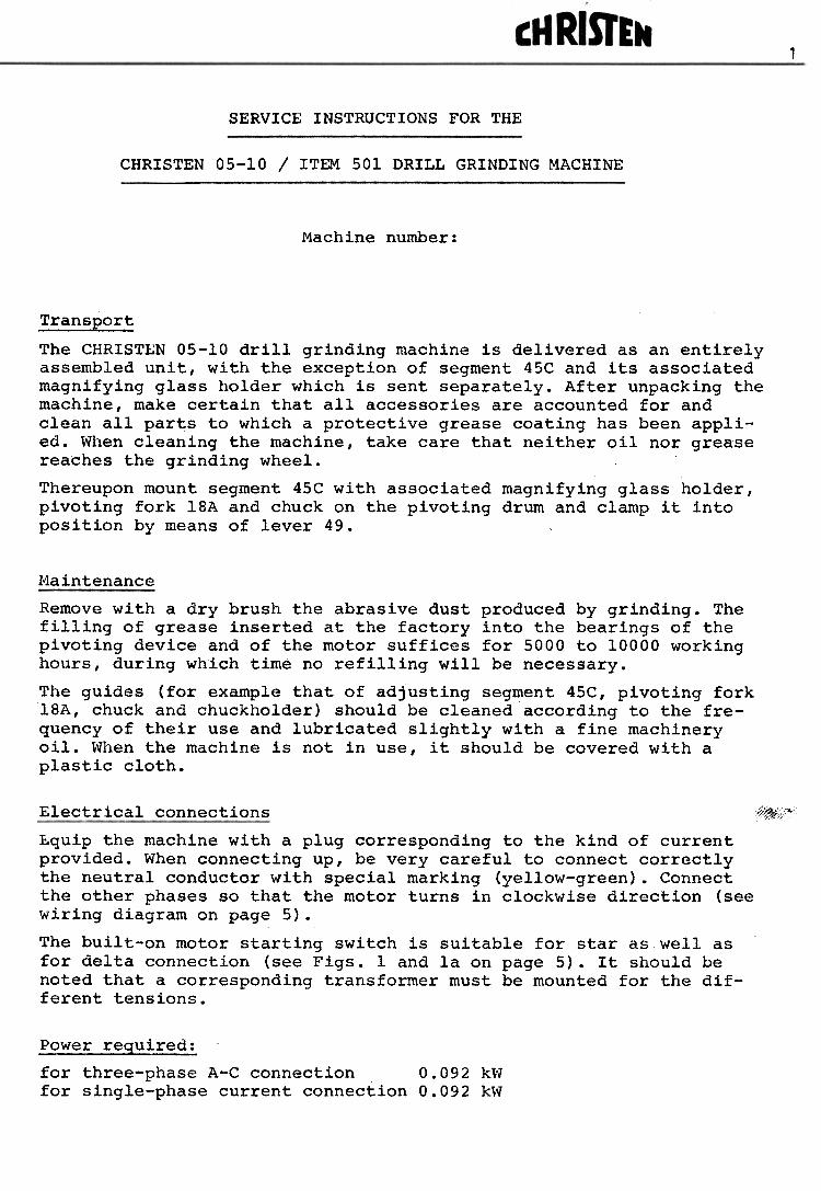
If there are divergences the grinding plane must be either behind orin front of the pivoting axis. Correct the grinding plane by adjustingthe setting surfaces on the centering tongs holder, which forms thestop for the grinding plane adjustment, in conjunction with thesetting gauge 34.
If the relief-ground facets for the right-hand drill overlap eachother as in Fig. 13, make the necessary correction by screwing for-ward (clockwise) the adjusting screw G.l Fig. 11 situated on theright-hand side.
Conversely if they fall short of the centre as in Fig. l3a this canbe corrected by screwing back the same screw.
,"'-
Fig. 13 a
The maximum correction is reached when the remaining error is dividedequally between positive and negative at right-hand respectively left-hand drills.
If exclusively right or left-hand drills are ground the error can beregulated by screwing forward or backward the adjusting screw G.lFig. 11 until the right-hand respectively left-hand drill shows atheoretically exact grinding picture.
setting gauge 34:
Carry out the final centering test with right and left-hand 4 mm(.16") drills.
If the relief-ground facets correspond to those attained in the test,set the left-hand adjusting screw G.2 Fig. 11 to scale in accordancewith the right-hand adjusting screw G.l. Then lock both screws withthe clamping screws H. Fig. 11 and finally seal the latter with whitepaint.

12
.p.
E n - ~ c->
Q ~ n CD
~ ., CJ
= Q ~ C""
)
'-11
Oo -J oS?
C)
9 o =-
0-
- E Ct)
- ~ n o ~ ... CD
:3 - .., OJ
- 0 :) ("')
0O C.-
JO0 ~ a o = Q
. (tI
s. - QJ
c:r CD
-t.
O ., IC J. = Q.
= IC O -t.
C = \0 "' CD
= n QJ
., 0" Q.
(\) Q.
J. (tI
- ~ - ~ 0- ~ ,...
~ <D
cr 0 :3 0- <D
0-n o ~ n co ~ , ~ = 0 ~ n <.1
1c:
>
0 - c..n
O -. "' a o ='
Q.
*(0
1)
~ = 0. A>
., 0. Q.)
n n CD
!1!
!1!
O -S ;' !1!
-C-')
O
Q.C
-')c:
-.
.,"0
~
--.C
D10
-.
-(')
(/)
(')
--. (/)
0.C
DC
: -
~S
&
-I
--(')
n
-0.
0.
::r
.,
., a-
o-
~= C
DQ
.Q.
-IC
D(1
) = C
D.'
Q.0
5 0.
., =
- Q
.-.
-.(1
) -.
~-C
D
~C
D--
51Q
.(/
) C
DC
II E
c:
CD
::r-.
., (1
)-C
D~
.,-
~
c§v.
CD
00
.,C
Dro (')
C)
., -5
1e
IQ
~C
D.,
,;,~
-"oQ
.=
.,r
oQ
. Q
c.-.
)C =
00
C)
.,Q
IQ J. = Q.
~ IC O
Q- U'I
O< -4 0 n J:>
:=0
CI;!
~- 0 b,
c...
~
- 0 0< -4 0 O §6 0= ~- ~
.,~
.':!:j
~(O
~
(O~
n
:)n
oQo
\Co
(!)
I (0
~
o m
o
~-+
-:)
-+-=
'Q
. Q
..~
m
~
m
.. 'Q
C.
'0
'Q.,-
+-
.'-0
0 0
0...
, ...
,..
\C
\C-.
, 0.
,J
-.~
-.
'""=
' '-"
::1c.
I
c.a
-.0'
>
-.a:
) =
'
7':
I':0.
,..
--+
-'""
.
~Q
. O
c.
I=~
~
~--
~"'
I "'
-e
.Ec:
c -.
N
-.=
(.
0)
-~
0'>
:.--.
: -.
='
-::1
:r
::s-
~
(0Q
. c.
~
~a
8m
(!
)
~
~.,
.,
If":;~
- -hc;)
N N O<
<--
t§i
~
""'
""'
§ ~ ...
,
---
(;')
0:.
O
-'~C
'"'o~
QO
CD
I
-nC
D~
(')
--10
0 O
Q
>C
De
., e
e --
.
0 C
D
S
-<-~
-C
DQ
. "'-
Q>
CD
'<
:'C
Q
. N
e'C
-.
n-S
...
a.
000
=
~Q
>..-
S
-.-,
.I ::3
(It
c.J1
'5?s
1
I-'
=00
:;,
CD
-,Q
. O
"'
3 -.
~Q
.-.
e =
-.
~10
"'C
D-S
Q.
.0
::3
CD
0;c.
c C
D:;s
-U
"lQ.
..'C
D=
..,
m-,
..,
-I
-QO
v.-:
:3."
' 10
.,...
, cm
-E
n..,
.-.
-0~
.'3
-::r
oe
-,
sm=
:;,
",Q
.'C
m~
'C
Q.
m
-, 0-Q
. ..0
,"' e
10C
D
..,
m
~-,
Q
.
:;, 10
"""
-+.
G")
- N C< -i ~ ".,
< J>- 0 ~
=c
0) .,~
0.
.~ ~ 0
,0
0')
c< - ~ ~ < ""'
- 0 .!..
o c ~ '<~ a ;:0 0) a "' .., ~ (/)"' , c (') c , (1)
(J")
3.
-.,
0 ., i9 "' ~ ~ c. s: 0> - <» "' 0 - :r <» c :r <»
~ - 0 ., c J. - - ~ ~ ~ ~ ~ n ::3"
~ <»
n :I: ~ "" -t ro,
z ~ .!..
0

cM RisrE8ICHRISTEN & CO. AG., BERN 13
Spare parts list for 05-10 Drill Grinding Machine
Valid from machine no.5500
Item 2/4/8/l7/l8A/35
Chuck holder complete
Item 2/8/17
Bush for chuck holder, graduatednut and chuck holder assembled
Item 3A
Length stop complete
Item 4 I
Chuck clampinq nut wi thoutsprin;
6Ar 1\", , ,
6A-2 6A-3
( .--rf/e-
6A-1
~
Item 6ACentering tongs compl.consist.of:6A-l Centering tongs6A-2 Pin
80 (3.15#) I tem 7
Locking nut for centering tqngs
:=0
1""Item 118
.Holder for centering tongscomp1
~;; ; 82 {3.23") ~ Item llB-l2 Cover plates and 2 specialscrews for centering tongs
--~I
!11-'-1
Item lSA/16A
Drill stop
Item l8ACone for pivotin9 fork withsprin9 loaded nut
Item 19A
Spring loaded nut for cone
~

ctl RisrE~CHRISTEN & CO. AG., BERN 14
Spare parts list 05-10, valid from machine no.5500
I~~0
(W)
Item 21
Flange for grinding wheel
~
-
Item 23
Balancing weight for Item 21
= 25 {.9~
Item 2710
(.39")'...
12.5
~
,
--
Key for motor shaft
I~'
I (. ~
-L.,
~
Item 28
Spring for key Item 2751 (2.0111)
,.,...~li)
'.
Item 29
Clamping screw for motor shaft
Item 30
Diamond wheel dresser
" -t- ~-E~:3- ~ ;<")
,,-.:. g)
..f 140 /5.51")
Item 31A
Spr inq for drill stop
Item 34
Setting gauge
Item 35
Spring for clamping nut Item 4
Item 39A
setting drum for backing-offang1e
(See selecting list of grinding wheels on page 12.)
&nl~

,II RISTEtlCHRISTEN & CO. AG., BERN 15
Spare parts list 05-10, va1Ld from machine no.5500
Item 45C
Segment for point angle setting600- 180°
Item 46C
Pivoting casting
Item 47A l ColfJD5 5~r ~
Special ball bearing with seal-
inCj rinq
Item 48
Locking pin for segment
Item 49
Lever for locking pin
Item 51
Microscope light holder
Item 52Filament lamp 6 volts, 1,2 wattrBa 7s
Item 53
Holder for filament lampMFG 035.2502
Item 54
Magnifying glass with frame(magnification 12 x)

cM RisrE~CHRISTEN & CO. AG., BERN 16
Spare parts list 05-10, valid from machine no.5500
l Item 55-1
6 volts transformer for 110,125,145, 220,240 v., 50 or 60 cycles
l Item 55-2
6 volts transformer for 380, 400,420, 440, 500 v., 50 or 60 cycles
-~ 61 (2.40"b'
ft
l Item 57 B
Drill settinq gauge
~
lItem 58
IBronze busb for cone Item l8A
Item 59
Wooden box for chuck holder andcollets
-116 { /f.S7") -
~
u~~
60-2 60-1~
~
~"'c,.(;;)
"-'-
Item 60Chuck holder compl. consisting of
Item 60-1 chuck holderItem 60-2 knurled chuck clamping
nut
Item 61-1Co11et for dia. .019.-.0598(0,5-1,5 nun)
Item 61-2
Co11et for dia. .059°-.118.(1,5-3,0 mm)
~
fq
..e~
~:
Item 61-3
Co11et for dia. .118.-.177g(3,0-4,5 mm)
Item 61-4
Co11et for dia. .177"-.25.(4,5-6,35 mm)
Item 62
Stop for pivoting unit

17
cH RisrE~CHRISTEN & CO. LTD., BERNE
Spare parts list 05-10, valid from machine no.5500
Item 65Plug for illuminationS lO2.AO5l
Item 66Socket for illuminationD lO2.AOSl
Item 67Security holder with bajonetjointFEI031.1431
Item 68Tumbler switch for illumination2036.5
270 (10.63"}=:: ,. -
I I
~
~I
Item 69Single-phase motor with switch
R~ Item 70
Three-phase motor with switch
~ ~"
!'t~
'tj~
Item 71
Switch for motor
]~~~

cH RisrEtlCHRISTEN & CO. AG., BERN 18
Spare parts list 05-10, valid from machine no.5500
Item 116A
Pivoting-shaft with housing,V-seal and two bearings
Item 117
Ballbearing for pivoting-shaft
Item 118A
Ballbearing for motor
Item 119
Ballbearing for motor
Item 121
V-seal

Special accessory Point thinning Attac~e!:!tItero506
For CHRISTEN 05-10 Drill Grinding Machine
General
The design and construction of the point thinning attachment is suchthat it can be employed for grinding almost all point thinning angles.
The drill I, whilst held in the chuck, is removed together with thecollet 60 and the pivoting fork 18A after loosening the spring loadednut, from the front pivoting device and placed on the point thinningattachment. The position of the main cutting edge adjusted for thegrinding of the drill point remains unchanged relative to the pivot-ing fork. After the point thinning operation, it is therefore possi-ble to regrind the drill point without any further adjustment of theposition of the drill. The length of the drill must however, protruderather more from the chuck, according to the drill support of the at-tachment.
To allow rapid changing of the chuck with pivoting fork from one bear-ing, to the other, we recommend operation without the spring loadednut, which keeps the cone of the pivoting fork in the bearing. Alwaysensure that the cone lies concentric in the bearing, by careful hold-ing of the collet.

20
There are the following adjusting movements to be distinguished:
a) Rotating the drill around its axis. Setting range of pieceo
74: 50 to the left and the right from the vertically po-sitioned cutting edge.
b) Pivoting the drill around the drill point. Setting range ofpiece 75: 38° to the left and the right from the drill po-sitioned 90 to the grinding wheel axis.
q) Pivoting the device around pivoting point 76, for setting:#be grinding position on the grinding wheel periphery.
';:~) Feeding the drill in radial direction to the grinding wheel
Setting handle 77.
e) Feeding the dri!l in axial direction to the grinding wheel.Setting handle 78.
Both movements d) and e) may be fixed by means of screws 79 and 80.According to the diameter of the drill to be thinned, the drill sup-port 81 must be adjusted in both directions parallel to the drillcaxis and in the longitudinal direction of the drill, according tothe grinding position at the periphery of the grinding wheel.
The drill support consists of two movable V-supports. The largersupport is for drills with diameters 4- 10 mm (0.157" -0.39") andthe smaller one for drills with diameters 1- 4 mm (0.039" -0.157")By re+easing screw 82, the drill support can be set in the desiredposition and adjusted parallel to the drill axis. The adjustment inthe longitudinal direction of the drill can be effected when re-leasi~g screw 83.
,~!:!n.q.ing Erocedure
Move the drill by means of pivoting part 84 to the grinding wheel.The p;voting movement is fixed by means of an adjustable stop 85.
After thinning the first cutting edge, remove from grinding wheeland rotate the drill (together with chuck and collet) around 1800Grind the second cutting edge in the same way as the first one.
The grinding movements should be effected by the operator's lefthand, at the same time the right hand is used for the setting anddividing movements. Bold left hand on handle 86. The thumb shouldpress the cone of the pivoting fork in the bearing and the colletsligh~ly to the rear.

Grinding whee!s
The grinding wheel 87 is mounted on a hub, which is mounted on themotor shaft and secured by means of a washer and screw 88. Accordingto the grinding operation, the hub with grinding wheel, or the grind-ing wheel only, can be reversed.
Cylindrical wheels (type Al) and cup wheels (type Dl) are availablein various hardnesses and grits (see grinding wheels'list page 22).
It is recommended to keep several grinding wheels in stock. Thisensures rapid point thinning for all the required grinding radiiwithout having first to dress the grind wheel to the desired form.
Dressing of the grinding wh~~!
The grinding wheel is to be dressed free by hand by means of a dress-ing stone. The form of the grinding wheel depends on the point thin-ning to be done.
Standard accessories for point thinning attachment item 506
1 saucer grinding wheel, dia. 2.953" x .394" x .630" {~ 75 x 10 x 16 mm), shape Dl, grain 80 , hardness J,
with flange
1 cylindrical grinding wheel, dia. 2.953" x .236" x .630" {~ 75 x 6 x 16 mm), shape A , grain 80, hardness J,
without flange
1 dressing stick
1 magnifying glass, magnification 2,5, complete with handle and adjustable support
1 spanner 22 mm
1 Allan key s = 4 mm
Special accessor)es for item 506
Item 89 grinding wheel flange (additional)
Item 93/94 grinding wheel diamond dresser with support
Item 94 diamond dresser separate
Item 95 dressing stick (additional)
I tern 104 spacer for gri ndi ng whee I .040" ( 1 mm)
For various grinding wheels see selecting list on page 22.

22
" VJ
0> :3 0. 0> , 0. 0> n n (0 "' "' O , (0 "'
0 , tD "' "' :. 00 "' r+-
o ~ r& - 0 , "' "C CO
n ~ - 0 , a "' Q)
:. c..
, C>
c..
c: "'
.
lO '-" N ~ -- '"" 0c::
--1
0 n > ~ ~ O = =
,ti
c: :3 10 tn CD
:3 n 0) "'5 ~ 0. CD
0. "'5 tn5? "' a o :. 0. n o ~ n "' ~ r+-
, "' r+-
o ~ n '-" 0= ~ , ... <""
)- ~ .0 O -.
JO
- 0 ., "Q ~.
~ ::r ~ =. ~ 10 0O "' a o :. 0.~ -.J I - =.
- ~ = C"')
c :3 n (0 :3 - , w ~ c :3 C"')
ton
O0 ...,
0
ECX
I-.
3 I - > - CX
I.0 ("
")0 ~ n (1
)~ -. "' -. 0 ~ ("
")'-" 00 "" 3 O ~ 0. cr 0) x- C
D .-+
CD
cr 0 :3 0- "' 0-
.V
)
G)
::I Q.
G)
-, Q.
G)
n n Ct>
tn tn O J. Ct> "'
tn ., ~.
\0 ::.-
\0 J. =0
S:
=0
\0 & ::.-
CJ)
~ 0 , -0 ~ =0 - :: =0
=. =0
\0< =i o ~ c= CX
)
== -..3
~ "' C-
0) 0 >
If> -~ O
0>,
:00- =
"0
-0
;::;:
::s
= gl::r
::s
I-0
.::s
=
::s
0.
::s
U)
\C
,O
0>
--.
\CU
) ::r
a w -10
-~.
o.::s
~.
g;-:
:s-1
0U
)e ::r = C
D
< --1
O C")
~ --1
= -.3 I '""' <~ 0 »""
< ~ O = = CD == -.J
!.. 0. n ~ "0 e ~ CD
~ - 0 , "0 S.
~ , , =:
~ :. ~ \0= = 9C-
< -4 0 0 c:=
~ 0:::
~~ -.3
.!- n (/)
"0 CD
~. ~ '< = :I CD
('I C -0 E ::r CD
~ 0 , -0 ~ :I - - :: :I =.
:I .0
~
- 0 0 9w
c::
-I 0 z .., c::
>= -.J
.!...
c:r
("")
c "0 e ::I"
." ~ -h c , "0 ~. :J ::I"
:J :. :J 10N N O 9~
U>
:;,-
~ (1)
U)
- , c " ..+0
c , (0:3
=C
D
00"'
..,"'
0- I
c c ~ -. '<rl- tD s = J. - :0:1
"' 3 "' , ~ (/)
-.,
0 , a "' 0> :0 C- 0> 0> (")
~ e (!> :0 0 - 0 , = :l ::s ~ ::s 3 0> (")
::r-
::s C!)
n ~ ;0:)
V)
~ m = 0 ..." I O
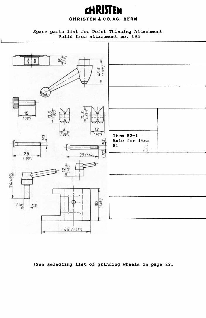
°cM RisrEtlCHRISTEN & CO. AG., BERN
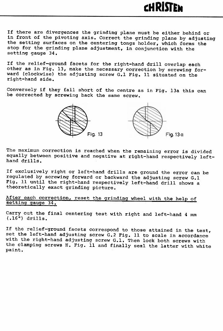
Spare parts list for Point Thinning AttachmentValid from attachment no. 195
Item 74
Angle adjustment segment
Item 76
Main clamping lever
Item 79 and Item 80
Allen screw M5 x 15
Item 81
Centerinq V-sup-
port(.02"-.314"}
Item 82-1Axle for item81
Item 82-2
V-support clamping lev~r
Item 83
Locking bo1 t
Item 85
Stop for vertical adju~~nt
(See selecting list of grinding wheels on page 22.
Item 81A;c
Centeringy-sup-
port(.02.'-.39")c
I tern c82~ lA''C',.Axle ,forcitem, "
81A

cH RisrE~CHRISTEN & CO. AG., BERN
Spare parts list for Point 'rhinning Attachment
Item 88
Allen screw M SxlS
Item 89Grinding wheel flange withoutwheel
Item 92
iiasher for wheel flange
Item 96AHolder for V-support.02" to .315" (0,5...8 mm)
Item 96CHolder for V-support.02" to .39" (0,5...10 mm)
Item 97
Special screw with pin
~
Item 98
Clamping lever for Item 74
Item 99
Mounting flange forZ.lagnetic-motor
Item 101
Clamping bolt for magnifyingglass
Item 102Adjustable support for magnify-ing glass complete
Item 103Magnifying glass with handle(2,5 x)
Item 103-1Magnifying glass with frame(2,5 x)
Item 103-2
Handle for magnifying glass
cH RisrE~CHRISTEN & COo AG., BERN 25
Spare parts list for Point Thinning Attachment
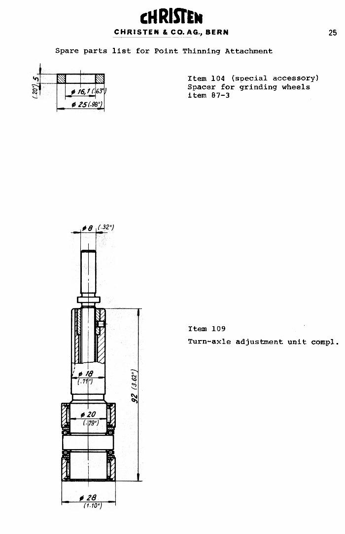
Item 104 (special accessory)Spacer for grinding wheelsitem 87-3
Item 109
Turn-axle adjustment unit comp1.

26
s cial Grindin Attachment for small 4rills item 507508
to Drill Grinding Machine CHRISTEN 05-10
6A 507-7507-1
507- 8 = item 65
Ran lication
Four facet grinding for t,~o fluted, left- and righthandcutting t,~ist- and flat drills of carbide or HSS.Grinding range 0,5...3 mm, clamping range 0,3...4 mm.Other dates see page 3.
»Q~~~n,a
Is the special grinding attachment for small drills item 507delivered as supplementary equipment, the mounting is effectedas follows:
-disconnect cable for illumination from base 50 A by pullingon plug 65 (see picture page 4)
-unscrew clamping scre", 49, move with segment 45 C out ofclamping range and take a,vay the standard grinding attachment
-mount the special grinding attacl1tnent, set the required pointangle and fix by means of' clamping screw 49
-connect cable for illumination
-change locking nut for centring tongs against friction nut forcentring tongs
27
Oper!tjon
The handling of the special grinding attachment for small drills ispr:tncipally'the same as for the standard grinding attachment.We subsequently only explain the variations to the basic machine:
-~l?!2B:-2.f-!~!-~!!!The drill is clamped in a special precision chuck holder with colletstype SchKublin B8/Art." 95, clamping range 0,3...4 mm. The colletsare available in steps of 0,1 mm. The drills are to clamp as shortas possible according to the point angle. The standard accessories ofthis attachment include one collet ~ 1 mm.
-How to set the drill
After having clamped the drill, loosen the chuck clamping nut 502-2for chuck 507-1 and swivel the whole unit under the length stop507-7. Thereby the front end of the clamping chuck rests againstthe stop of the plate 507-6 for drill setting. The clamping chucl{with the drill is now to set to length by means of the down pushedlength stop 507-7 and the clamping nut 502-2 slightly tightened sothat the clamping chuck can yet be turned.Swivel afterwards the clamping chucl{ under the microscope. Therebythe plate 507-6 centers the chuclt according to the reticule in themicroscope. The drill cutting edge is now to set parallel to thevertical line in the reticule. Depending on the expected quantityof material to grind off and the ascent of the flute, the grinding-reserve is to consider on setting the drill.After setting, the clamping nut 502-2 is to tighten, the clampingchuck back-moved and the drill put on the drill stop in the cent-ring tongs. On tightening the friction nut (7A) for centring tongsthe drill will be properly centered.
-~!!~~!!:~.2~::!!!
According to instructions given on page 7.
M!£roscope
The magnification of the microscope is 20 x, field ~ 3 mm. Thereticule can clearly be set on occular 507-4.
Grinding wh2els
Use within the grinding range of 0,5...3 mm grinding wheels withfine grain. For selection see page 12.on ordering the special grinding attachment for small drills (item 508)mounted on the machine (without standard grinding attachment) a specialdressing diamond '/1 10 mm (item 507-9) suitable to clamping chuck'/1 10 mm is delivered. on delivery as supplementary equipment (item 507)the grinding wheel is dressed with the standard dressing diamond '/1 8 mm(item 30) of the standard clamping chuck '/1 8 mm.
28
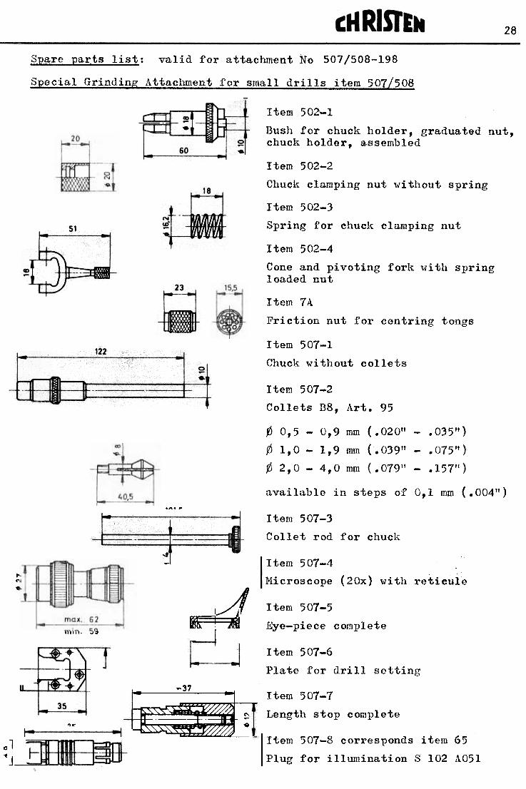
Spare parts li~:!:: valid for attachment No 507/508-198
s ecial Grindin Attachment for small drills item 501508
Item 502-1
Bush for chuck holder, graduated nut,chuclt holder, assembled
Item 502-2
ChQck clamping nut without spring
Item 502-3
Spring for chucl~ clamping nut
Item 502-4
Cone and pivoting forl~ with springloaded nut
Item 7A
Friction nut for centring tongs
Item 507-1
Chuck without col1ets
Item 507-2
Collets B8, Art. 95
(J 0,5- 0,9 mm (.020" -.035")
(J 1,0- 1,9 mill (.039" -.075"
~ 2,0 -4,0 illm .07911 -.157"
available in steps of 0, 1 mm { .004" )
101,5Item 507-3
Collet rod for chuck
...
N..
l Item 507-4
Microscope (20x) with reticule
f!!i Item 507-5
Eye-piece completemin. 59
r-35
LI)
~
Item 507-6
Plate for drill setting~
..37
~
Item 507-7
Length stop complete...35
l Item 507-~ cor~esp~nds item 65
Plug for ~11um~nat1on S 102 A0510)-,