SERIOUS INCIDENT FINAL REPORT - Aviation Safety … · SERIOUS INCIDENT FINAL REPORT Aircraft: ......
37
AIR ACCIDENT AND INCIDENT INVESTIGATION COMMISSION SERIOUS INCIDENT FINAL REPORT Aircraft: BOEING 737/800 Aircraft registration marks: D-AXLF Operator: XL Airways Germany Place of incident: Airspace under the jurisdiction of АСС Belgrade Date of incident: 18 October 2008. Time of incident: 05.19 (UTC) Belgrade, May 2010. CIVIL AVIATION DIRECTORATE OF THE REPUBLIC OF SERBIA
Transcript of SERIOUS INCIDENT FINAL REPORT - Aviation Safety … · SERIOUS INCIDENT FINAL REPORT Aircraft: ......

AIR ACCIDENT AND INCIDENT INVESTIGATION COMMISSION
SERIOUS INCIDENT FINAL REPORT
Aircraft: BOEING 737/800 Aircraft registration marks: D-AXLF
Operator: XL Airways Germany Place of incident: Airspace under the jurisdiction of
АСС Belgrade Date of incident: 18 October 2008. Time of incident: 05.19 (UTC)
Belgrade, May 2010.
CIVIL AVIATION DIRECTORATE OF THE REPUBLIC OF SERBIA

2
CONTENTS Page
Introduction ................................................................................................................................................................................................ 3
List of abbreviations …………………………………………………………………………………………………………………. 4
I FACTUAL INFORMATIONS ................................................................................................................................ 6
1.1 History of the flight …...................................................................................................................................................... 6
1. 2 Injuries to persons ............................................................................................................................................................ 7
1. 3 Damage to the aircraft ................................................................................................................................................... 7
1. 4 Damage to the third party ........................................................................................................................................... 8
1.5 Personnel information …................................................................................................................................................ 8
1.6 Aircraft and engine information ............................................................................................................................. 9
1.7 Meteorological conditions ……….............................................................................................................................. 10
1.8 Navigation and communications aids ……………………….............................................................................11
1.9 Airport information ....................................................................................................................................................... 11
1.10 Flight recorders ................................................................................................................................................................ 11
1.11 Situation at the site ………............................................................................................................................................. 11
1.12 Medical and pathological information .............................................................................................................. 11
1.13 Fire, action of firefighting brigade and evacuation ……………………………...………...................... 12 1.13.1 Observed fire ......................................................................................................................................................................... 12 1.13.2 Action of firefighting brigade ........................................................................................................................................ 12 1.13.3 Evacuation and rescue of the passengers and crew members ....................................................................... 13
1.14 Survival aspects ................................................................................................................................................................ 14
1.15 Test and research ……………….................................................................................................................................... 14
1.16 Search and rescue ........................................................................................................................................................... 15
II INCIDENT ANALYSIS .............................................................................................................................................. 16
2.1 History of the engine and its maintenance …………………………............................................................. 16
2.2 Flight recorders data analyses ................................................................................................................................ 17 2.2.1 FDR data analysis ............................................................................................................................................................... 17 2.2.2 CVR data analysis ............................................................................................................................................................... 21
2.3 Analysis of the performed engine inspections ............................................................................................. 22 2.3.1 A preliminary engine inspection ….............................................................................................................................. 22 2.3.2 Inspection of engine in authorized engine workshop ……................................................................................ 24 2.3.3 Special analyses of engine components and oil ……………................................................................................. 27 2.3.4 Conclusions on the basis of engine inspections ..................................................................................................... 30
2.4 History of No 4 bearing failures and taken measures ............................................................................ 31
III CONCLUSIONS .............................................................................................................................................................. 34 3.1 Conclusions related to emergency landing of aircraft ........................................................................... 34 3.2 Conclusions related to engine shut-down ....................................................................................................... 34 3.3 Conclusions related to nature of incident ………………............................................................................... 35
IV CAUSE OF SERIOUS INCIDENT .................................................................................................................... 35
V SAFETY RECOMENDATIONS ......................................................................................................................... 36
VI DIFFERENT OPINIONS .......................................................................................................................................... 36
LIST OF APPENDIXES ............................................................................................................................................ 37

3
Introduction
The results of investigation of serious incident of Boeing 737/800, registered D- AXLF, which took place on 18 October 2008, are presented in this report. There were not injured persons in the incident, and the aircraft suffered serious damage to the left engine (engine no. 1), as well as damage to structural elements and air system on the left wing.
The copies of the Final Report Draft were sent to all interested parties and their comments have been incorporated in the presented paper.
Commission for investigation of this serious incident (hereinafter: Commission), composed of a chairman and six members, was appointed by the Director General of Civil Aviation Directorate of the Republic of Serbia on 20 October 2008. On 5 November 2008 the Commission was extended with another member.
Since the Commission estimated that a serious incident was of interest to the security of civil aviation in the world, in accordance with national regulations and ICAO standards the following organizations have been notified of the incident:
� German Federal Bureau of Aircraft Accident Investigation (BFU) - authorized institution of Germany for investigation of civil aviation accidents (as the body of the State of Registry and the State of Operator of the aircraft),
� National Transportation Safety Board (NTSB) - U.S. authorized institution for investigation of civil aviation accidents (as the body of the State of Design and the State of Manufacture of the aircraft),
� International Civil Aviation Organization (ICAO) - due to serious incident of aircraft whose maximum mass is greater than 5700 kg
Notice of accident for the first two institutions was submitted on 20 October 2008 and for the third one it was done on 6 November 2008.
German Federal Bureau of Aircraft Accident Investigation was appointed his authorized representative to participate in the investigation of incidents. Also the representatives of aircraft manufacturer (Boeing Company), engine manufacturer (CFM International) and operator (XL Airways) were sent to the scene.
Before the end of the investigation former chairman of the Commission died during October 2009. and the new chairman of the Commission was appointed on 22 December 2009 while members of the Commission remained the same.
This investigation was carried out in accordance with the Air Traffic Law, RReegguullaattiioonn oonn AAcccciiddeenntt aanndd IInncciiddeenntt IInnvveessttiiggaattiioonn aanndd provisions of Annex 13 to the Chicago Convention.
In accordance with the aforementioned documents the sole purpose of the investigation of the aircraft serious incident is to prevent future accidents or serious incidents. It is therefore not the purpose of this investigation to determine blame or clarify questions of liability.

4
List of abbreviations
The most important abbreviations that are used in the Report are given in alphabetical order. Some other abbreviations are explained in the text.
ACC - Area Control (Centre)
AGB - Accessory Gearbox
AIP - Aeronautical Information Publication
APP - Approach Control (Service)
AVM - Airborne Vibration Monitoring
BKN - Broken (clouds)
BSI - Boroscope Inspection
BMOD - Bill of Material Object Damage
CAS - Computer Airspeed
CMM - Coordinate Measuring Machine
CSLSV - Cycles Since Last Shop Visit
CSN - Cycles Since New
EGT - Ehxaust Gas Temperature
FG - Fog
FL - Flight Level
FMC - Flight Management Computer
F/O - First Officer
FOD - Foreign Object Damage
FWD - Forward
HPC - High Pressure Compressor
HPT - High Pressure Turbine
IDG - Integrated Drive Generator
IFSD - Inflight Shutdown
ILS - Instrumental Landing System
L/E - Leading Edge
LPC - Low Pressure Compressor
LPT - Low Pressure Turbine
MCD - Magnetic Chip Detector
PIC - Pilot In Command
RVR - Runway Visual Range
RWY - Runway
SCT - Scattered (clouds)

5
S/N - Serial Number
TCC - Terminal Control (Center)
T/E - Trailing Edge
TEMPO - Temporary
TGB - Transfer Gearbox
TSLSV - Time Since Last Shop Visit
TSN - Time Since New
TWR - Aerodrome Control (Tower)
TWY - Taxiway
UTC - Coordinated Universal Time
VHF - Very High Frequency

6
I FACTUAL INFORMATIONS
1.1 History of the flight On 18 October 2008 the Boeing 737/800 aircraft of German charter company XL Airways Germany, registered D-AXLF, flew on GXL614 flight from Frankfurt (EDDF) in Germany to Antalya (LTAI) in Turkey.
There were 189 persons in the aircraft: 182 adult passengers, 1 child and 6 crew members.
The aircraft entered the airspace under the jurisdiction of the ACC Beograd point GUBOK (5.9 nautical miles northwest of the VOR DER), the flight level FL350, at 05.19 UTC.
The first radio contact with the ACC Belgrade, the pilot of the aircraft GXL614 established in 05.19.29 UTC by the phrase "MAY DAY, MAY DAY, MAY DAY" which means that the aircraft was in DISTRESS situation. He expressed concern regarding a possible engine failure and requested a landing at the nearest airport. Air Traffic Controller proposed landing at Belgrade airport and the pilot agreed.
ACC Belgrade immediately made the necessary coordination with the ACC Zagreb, TCC Belgrade and competent military authorities ensure priority and lowering of aircraft for landing at Belgrade airport.
At 05.29.43 UTC, on the question of the flight controller, the pilot requested the help of the fire brigade after landing on the ground with the explanation of a failure of the engine, that he probably currently has two engines, but with the vibrations.
Intensive coordination of the tower with the fire brigade began at 05.32.12 UTC and lasted until the moment of extinguishing the fire after landing.
At 05.33.47 UTC, the aircraft was transferred to the approach flight control of Belgrade.
In the first contact with approach flight control in 05.34.30 UTC, the pilot confirmed the DISTRESS condition of the aircraft by the phrase "MAY DAY". He received instructions for the ILS approach path 12 and continued to descent.
The pilot received information that is in force Low Visibility Procedures CAT II, RVR 2000 meters.
At the request of the pilot, aircraft was vectored to enter the ILS, the pilot has confirmed that 182 passengers plus one child, 6 crew members, 7 tons of fuel, that is the problem with the left engine and that no hazardous materials in the cabin.
At 05.42.51 UTC the pilot confirmed that the established path for the ILS 12 and received the instruction to go to the tower frequency Belgrade (LABUD point).
The first contact with tower controller pilot had at 05.43.17 UTC when he confirmed the DISTRESS situation of the aircraft by the phrase "MAY DAY" and received approval for landing. The pilot was informed about meteorological data: vertical visibility of 480 meters, 800 meters observed visibility, RVR: 3500 meters at the point of contact, 3300 meters at the central third of the runway, 4400 meters the last third of the runway.
At 05.46.51UTC, flight controller gave the pilot instructions to turn off engines after landing.
At 05.48.11 UTC, the controller gave instruction to the pilot to prepare for the evacuation of passengers and warning that the left engine was in flames.
In the meantime, the Air Trafic Control informed about the situation all the relevant services at the airport which were responsible for providing aircraft for landing in case of emergency.

7
All take off flights were canceled and all aircrafts that were in the starting phase or taxiing were informed about the expected delays.
When landing from the direction 12 aircraft touched the runway at about 600 meters from the threshold 12 and stopped at around 1900 meters of the threshold 12. Fire vehicles were distributed to the joints of TWY C and TWY D according to the schedule for the emergency landing.
Extinguishing agents were sprayed into the engine for some 30 seconds from the moment of stopping of the aircraft, and passenger evacuation was completed by about 40 seconds of its beginning. All passengers and crew members were transported by bus and van vehicles to the airport building.
1. 2 Injuries to persons There were not injured persons in the incident.
1. 3 Damage to the aircraft After landing, firefighting, evacuation and rescue of passengers and crew and cooling, the aircraft was transported from the site in the hangar of JAT - Technique that has the authority to maintain this type of aircraft. The aircraft was secured and only authorized persons had access to the aircraft.
The representatives of the aircraft manufactures (hereinafter - the manufacturer) made an overview of the damage of the aircraft on 21 October 2008. The situation recorded during this overview is given in the document AIRCRAFT SURVEY REPORT (hereinafter - ASR) which was made on 22 October 2008. The document is given in Appendix 1 of this Report.
The document contains 28 damages components, subassemblies or assemblies. All the damages can be conditionally divided into two groups:
1. Damage of the engine in position 1 and
2. Structure damages as a result of fire
The damages numbered 26 and 27 in ASR belong the first group. Damages of the engine are described in detail in Chapter 2.2 of this Report.
Damages of the second group can be grouped by the basic assemblies:
� Left wing assembly - a total of 17 damages (numbered 1 to 6, 12 to 17, 22 to 25 and 28 in ASR) which is related to the flap track fairings, panels, spoiler number. 5 and his actuator, torque tubes, angle gear box, some bearings, seals,
� engine strut - a total of 5 damages (numbered 7 to 11 in ASR) which is related to the strut fairing panels,
� hydraulic system - 1 damage (numbered 18 in ASR), which refers to the tubing,
� electrical equipment - 1 damage (numbered 19 in ASR), which refers to the wire bundle and
� Command system - 2 damages (numbered 20 and 21 in ASR), which relate to the cables and pulleys.
The manufacturer has found that all the aircraft structure damages occurred due to extreme heat exposure as a result of engine failure and fire that arose.

8
For most of the damages (22 of 28) manufacturer foresees removal of damaged parts and their replacement with new parts. For three damages it was foreseen the repair of damage, and for three damages (26, 27 and 28) pertaining to the engine itself, thrust reverser and the surrounding structure, the decision on further procedure was leaved to the operator ("Customer Responsibility").
The photos that were made during the aforementioned overview of the aircraft, which illustrate part of these damages, are given in Appendix 2 of the Report.
1. 4 Damage to the third party There was no damage to the third party.
1.5 Personnel information � Captain
Age: 55 Sex: Male License: Air Transport Pilot License ATPL(A)
No. 3311004902 issued by the Federal Republic of Germany on 16. February 1990 in accordance with the requirements of JAR-FCL1
Date first employed by airline: 01 May 2007 Type rating on B737 300-900: valid until 31 May 2009 Rating for CAT III: valid until 31 May 2009 Last line check: 30 June 2008 License Proficiency Check (LPC): 24 May 2008 Operator Proficiency Check (ОPC): 12 November 2007 Medical aptitude class 1: 29 October 2007 until 19 November 2008 Flight experience: 13353 flying hours total 1053 flying hours on type
281 flying hours, all on type, in the previous three months (01 July until 18 October 2008) 45 flying hours, all on type, in the previous 30 days
7.30 flying hours in the previous 24 hours
� Co-pilot
Age: 24 Sex: Male License: Commercial Pilot License СPL(A) No.
SE-8406199458 issued by the Authority Swedish CAA/Luftfartsstyreisen on 04 June 2007 in accordance with the requirements of JAR-FCL1
Date first employed by airline: 15 March 2008 Type rating on B737 300-900: valid until 31 October 2008 Rating for CAT III: valid until 31 October 2008 Last line check: 19 June 2008 License Proficiency Check (LPC): with TRTO for Type rating on B737 300-900

9
Operator Proficiency Check (ОPC): 12 April 2008 Medical aptitude class 1: 24 January 2008 valid until 30 January 2009 Flight experience: 750 flying hours total 450 flying hours on type
264 flying hours, all on type, in the previous three months (01 July until 18 October 2008) 100 flying hours, all on type, in the previous 30 days
0 flying hours in the previous 24 hours
� Purser
Age: 32 Sex: Male Date first employed by airline as Cabin Attendent: 15 April 2006 Date appointed as purser 01 May 2008
� Cabin Attendent 1
Age: 37 Sex: Female Date first employed by airline as Cabin Atendent: 19 April 2008
� Cabin Attendent 2
Age: 20 Sex: Female Date first employed by airline as Cabin Atendent: 19 April 2008
� Cabin Attendent 3
Age: 23 Sex: Male Date first employed by airline as Cabin Atendent: 15 April 2006
1.6 Aircraft and engine information Type of aircraft: Boeing 737-800 Aircraft S/N: 28218 First flight: 24 November 1998 Certificate of airworthiness: 34129 Date of issue: 05 December 2007 Date of expiry: 10 December 2008 Operator: XL Airways Germany
Note: Certificate of airworthiness was issued 05 December 2007 when the aircraft was British registration G-XLAB. But, on 28 April 2008 the aircraft was re-registered by the German aviation authorities with registration D-AXLF.

10
Type of engine: CFM56-7B26 Engine S/N: 874281 TSN: 31045 hours CSN: 11250 TSLSV: 3124 hours CSLSV: 1243
1.7 Meteorological conditions METAR LYBE 180500Z 17004KT 130V200 0300 R12/0375N R30/1200VP2000 FG SCT003 05/05 Q1026 TEMPO BKN002
METAR report for Airport Belgrade LYBE Date/Time of observation: 18th day in month at 05:00UTC Wind mean direction: 170 degrees true north Wind speed: 4 knots Total directional variation: between 130 to 200 degrees true north Prevailing visibility: 300m RVR RWY 12: 375 m; tendency: no change RVR RWY 30: variable from 1200m to more than 2000m Present weather: Fog Cloud amount: Scattered (3 to 4 oktas) Cloud height: 300 feet Temperature: 5 degrees Celsius Dew point: 5 degrees Celsius QNH: 1026 hPa TREND forecast for Next 2 hours: Temporary cloud amount: broken (5 to 7 oktas), cloud height: 200feet
METAR LYBE 180530Z 17004KT 0500 R12/0700V1500 R30/P2000U FG SCT003 06/05 Q1026 BECMG 0800
METAR report for Airport Belgrade LYBE Date/Time of observation: 18th day in month at 05:30UTC Wind mean direction: 170 degrees true north Wind speed: 4 knots Prevailing visibility: 500m RVR RWY 12: variable from 700m to 1500m RVR RWY 30: more than 2000m; tendency: up Present weather: Fog Cloud amount: Scattered (3 to 4 oktas) Cloud height: 300 feet Temperature: 6 degrees Celsius Dew point: 5 degrees Celsius QNH: 1026 hPa TREND forecast for Next 2 hours: Becoming prevailing visibility: 800m
Low Visibility CAT II Operation was effective.
11
AIP Serbia and Montenegro, Part 3-Aerodromes,AD 1.1-3, 4.2: “Category II (CAT II) operation: A precision instrument approach and landing with a decision height lower than 60 m (200 ft), but not lower than 30 m (100 ft) and RVR not less than 350 m.”
Meteorological situation did not significantly affect to the occurrence.
1.8 Navigation and communications aids At time when the occurrence happened all ground navigation, communication, surveillance and meteorological aids at ACC Belgrade and TCC Belgrade was correct and in use.
1.9 Airport information Belgrade airport "Nikola Tesla" has runway with length of 3400 m, enabling a safe landing and departure of all types of aircraft.
Belgrade airport "Nikola Tesla" has VII firefighting category, so it has trained personnel, equipment, vehicles and other necessities for the successful rescue and fire-fighting of Boeing 737/800 and larger aircrafts.
1.10 Flight recorders The following devices have been installed on this aircraft: Flight Data Acquisition Unit (FDAU), manufacturer: Teledyne Controls, P/N:2233000-815, S/N:00479; Flight Data Recorder (FDR), manufacturer Honeywell, P/N:980-4700-042, S/N:7033, and Cockpit Voice Recorder (CVR), manufacturer: Fairchild Model FA 2100, P/N 2100-1020-00, S/N 00258.
1.11 Situation at the site After the firefighting, evacuation and rescue of passengers and crew members, their driving to the airport building and cooling of the engine and landing gear, the aircraft remained some time at the place where it landed (Figure 1.1). After that, the aircraft was transported to the hangar of JAT - TECHNICS.
Until the arrival to JAT - TECHNICS any overview into the engine, structure and installation of aircraft was not carried out.
Figure 1.1
1.12 Medical and pathological information Not applicable.

12
1.13 Fire, action of firefighting brigade and evacuation
1.13.1 Observed fire
Although at the time of receiving notice of a planned emergency landing in the area of the airport was low visibility, the conditions have since improved so that tower controller noticed that the left engine og the aircraft was in flames and he informed pilot about that fact more before the plane touched the runway.
1.13.2 Action of firefighting brigade
That very morning, the airport firefighting brigade consisted of 10 professional firefighters. On duty were the commander of the fire department, operator, a rapid vehicle “PANTHER” (a driver and two firemen), two main vehicles, “SCAMEL” (a driver and a fireman), and “MAGIRUS” (a driver and a fireman), and one technical vehicle (driver). All vehicles were equipped with corresponding equipment for rescue and fire extinguishers.
The overall capacity of the firefighting vehicles is given in Table 1.1, and the appearance of vehicles "PANTHER," "SKAMEL and MAGIRUS" is shown in Figure 1.2 .
Table 1.1
Figure 1.2
Figure 1.3
13
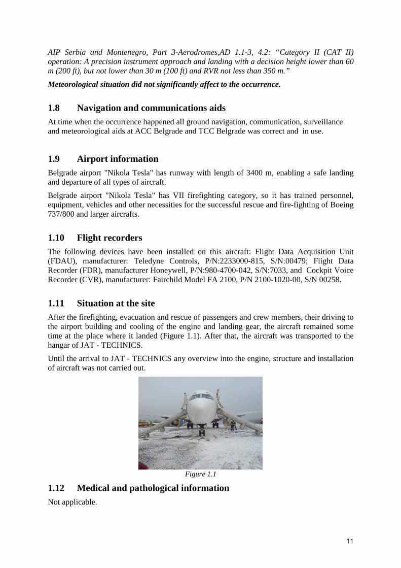
Acting in accordance with the Plan for Emergency Situations at the Airport Belgrade, firefighting vehicles were deployed at the intersection points C and D of the taxiway and the runway as it is schematically depicted in Figure 1.3.
According to recommendations from the tower, the pilot shut down the engines as soon as the aircraft touched runway.
Vehicles arrangement around stopped aircraft is schematic depicted in Figure 1.4, while Figure 1.5 shows the way of extinguishing the fire on the left engine.
Figure 1.4 Figure 1.5
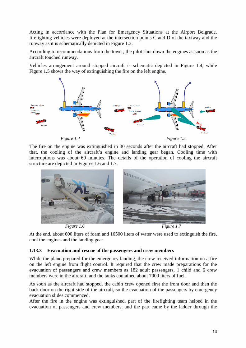
The fire on the engine was extinguished in 30 seconds after the aircraft had stopped. After that, the cooling of the aircraft’s engine and landing gear began. Cooling time with interruptions was about 60 minutes. The details of the operation of cooling the aircraft structure are depicted in Figures 1.6 and 1.7.
Figure 1.6 Figure 1.7
At the end, about 600 liters of foam and 16500 liters of water were used to extinguish the fire, cool the engines and the landing gear.
1.13.3 Evacuation and rescue of the passengers and crew members
While the plane prepared for the emergency landing, the crew received information on a fire on the left engine from flight control. It required that the crew made preparations for the evacuation of passengers and crew members as 182 adult passengers, 1 child and 6 crew members were in the aircraft, and the tanks contained about 7000 liters of fuel.
As soon as the aircraft had stopped, the cabin crew opened first the front door and then the back door on the right side of the aircraft, so the evacuation of the passengers by emergency evacuation slides commenced. After the fire in the engine was extinguished, part of the firefighting team helped in the evacuation of passengers and crew members, and the part came by the ladder through the

14
front left door and searched the interior of the aircraft. During the search they did not find anybody and the captain was the last who left the aircraft.
The passengers and crew members were evacuated onto the grass area that separates the taxiway and the runway. The evacuation of all passengers and crew members was completed in 40 seconds after the aircraft had stopped.
Support staff directed the passengers towards the airport area destined for evacuation and towards the taxiway, and when the busses and minivans had arrived, all passengers and crew members were transported to the terminal building where they were provided all necessary assistance.
The passengers were carried to Antalya by another aircraft.
1.14 Survival aspects Not applicable.
1.15 Test and research The following testing and research where made during the investigation of this incident:
1. The appropriate data, statements and reports have been collected from services that were directly involved in this event. These services are:
� airport fire fighting and rescue service, � ACC Belgrade and � TCC Belgrade.
2. The information about the history of the engine and its maintenance was collected from the operator.
3. On the site, i.e. in the hangar of JAT-TECHNICS, authorized team of the aircraft manufacturer carried out the review of the damage to the aircraft and the results of the examination are given in the document AIRCRAFT SURVEY REPORT of 22 October 2008.
4. The damaged engine was removed from the aircraft in the hangar of JAT-TECHNICS and a preliminary review of the engine was conducted in the presence of engine manufacturer (CFM International) representatives.
5. Authorized service of JAT-TECHNICS performed BSI of the engine and issued BOROSCOPE INSPECTION REPORT (REPORT BSI) of 21 October 2008.
6. Experts of JAT-TECHNICS, in the presence of an authorized member of the Commission, removed the raw data from the Flight Data Recorder (FDR).
7. In cooperation with the German civil aviation authorities, i.e. German Federal Bureau of Aircraft Accident Investigation (BFU) the reading of data from the Flight Data Recorder and Cockpit Voice Recorder was performed in their corresponding laboratory in Braunschweig from 24 to 28 November 2008.
8. Complete review of the status of components, sub-assemblies and assemblies of the engine was performed in an authorized service SR Technics Switzerland, Engine Service Center, CFM56 Overhaul Engineering TTEB, CH-8058 Zurich Airport. Disassembly of the engine started 19 November 2008 and the entire job was completed 16 November 2009 when a corresponding report (Engine Shop Visit Report
15
- XL Airways Germany GmbH, GXL C874281 SVN 002, CFMI, CFM56-7B26) was published.
9. In determining the causes of engine failure some engine components are sent for further specialist examination and analysis:
- bearing No. 4 was sent to a detailed metallurgical examination in the CFM/Snecma Investigation Laboratory, Villaroche, France,
- Lubrication Unit (PN: 340-400-004-0) was sent to a detailed examination in the Techspace Aero, Liege, Belgium,
- The Main Oil Filter (PN: QA06422) is sent to a detailed examination in the laboratory of company Spectro Oil,
- Two samples of oil from the MCDs (PN: 335-296-304-0) were sent to the detailed analysis in the same laboratory,
- A detailed visual and boroscope inspection of scavenge and supply lines of lubrication system, as well as inlet and outlet area of the involved components were performed. Nine samples from the characteristic places in the oil circuit were taken and sent for analysis in Exxon Mobil Laboratory, Paulsboro, NJ , USA.
1.16 Search and rescue Not applicable.

16
II INCIDENT ANALYSIS
2.1 History of the engine and its maintenance Information about the history of the engine and review of performed overhauls and repairs are given in Table 2.1. This data was submitted to the Commission by the operator of the aircraft.
Table 2.1
The engine CFM56-7B26 with serial number 874281 is installed as a new at position no. 1 on the Boeing 737-800, serial number 28226, registration mark G-OKDN.
After 8071 working hours and 3357 cycles, the engine was on the same aircraft set to position no. 2 and registration of the aircraft was also changed on G-XLAA.
After additional 3372 (11443 total) hours of work and 1088 (4445 total) cycles, the engine went to an authorized repair shop Snecma Service Saint-Quentin-en-Yvelines, France, due to the need of replacement blades in high pressure turbine. On that occasion, some interventions on a high pressure turbine rotor and the high pressure turbine stator were performed.
After the engine was completely overhauled it was set to the position no. 1 on the same aircraft.
After additional 13831 (25274 total) hours of work and 4741 (9186 total) cycles engine was installed in position No. 1 on the Boeing 737-800, serial number 28218, registration mark G-XLAB.
The previous table shows that the engine went to the repair after additional 318 (25592 total and 14149 since the last overhaul) hours of work and 122 (9308 total and 4863 since the last overhaul) cycles. There is no detailed information about this repair.
After the overhaul the engine is installed in position No. 2 on the Boeing 737-81Q, serial number 29051, registration mark G-XLAC.
After an additional 2327 (27919 total) hours and 699 (10007 total) cycles, the engine was removed from the aircraft and sent to the authorized motor repair workshop SR Technics Switzerland. The reason for the overhaul was the performance restoration and repair of damage due to the contact between the stator and rotor. All affected parts were refurbished or replaced according to the relevant manuals and to the workscope, in order to restore the engine performance. On that occasion, the ball bearing no. 3 was replaced.
After the overhaul, the engine was reinstalled to the position No. 1 of the aircraft with registration mark G-XLAB. In the meantime the registration of the aircraft was changed on D-AXLF.
17
2.2 Flight recorders data analyses
2.2.1 FDR data analysis
German Federal Bureau of Aircraft Accident Investigation (BFU) has its own laboratory that deals with reading data from the FDR and CVR.
Raw data which were in binary form downloaded from FDR in JAT-TECHNICS did not enable the analysis of these data. Therefore, the Commission addressed the authorized representative BFU to do, in their laboratory, translation of binary form in engineering units which enables the analysis of results, display results in the form of tables and graphics.
Data from the FDR were prepared in the form of graphics and tables. The following graphics have been prepared and submitted to the Commission:
� OVERLOOK – graph gives an overview of the entire flight from the moment of takeoff to landing with the basic parameters of the flight: UTC, altitude, CAS, heading angle and EGT for both engines,
� INCIDENT – graph gives the basic parameters of both engines from the moment when the problem occurs on the engine no. 1 (05:17:10 UTC) until the end of the flight (05:46:37 UTC): UTC, altitude, N1 and N2 of both engines, both engines EGT,
� DESCENT – graph gives the basic parameters of flight and position of command surfaces in the landing phase of aircraft: UTC, altitude, CAS, vertical acceleration (g), angles of heading, roll, pitch and rudder and activation VHF
� FLIGHT - graph gives the basic parameters of flight and position of command surfaces during the entire flight: UTC, altitude, CAS, vertical acceleration (g), angles of heading, roll, pitch and rudder and activation VHF
� ENG-L_cor – graph gives the essential parameters of the engine no. 1 and the level of vibration on it: UTC, N1 and N2, EGT for both engines, the thrust handle position (TRA - Thrust Resolver Angle), the parameters of vibration at various stages of engine (CN2 - the vibrations of high-pressure compressor, TN1 - the vibrations in low pressure turbine and TN2 - vibrations in high pressure turbine), oil system parameters (temperature, pressure and oil quantity) and condition of autothrotle (engaged or not)
� THRUST_INC – graph gives the basic parameters of flight and engine parameters in the take off phase: the elapsed time, CAS, altitude, N1 and EGT of both engines, the condition of autothrotle (engaged or not)
� VIB_INC - graph gives all the parameters of the motor No. 1 vibration during the incident phase of flight: UTC, altitude, N1 and N2 for engine No. 1, EGT for both engines, CN2 - the vibrations of high-pressure compressor, TN2 - the vibrations of high-pressure turbine and the angles of imbalance on fan and LPT
� VIBRATION - graph gives all the parameters of engine No. 1 vibration and pressure during the incident phase of flight: UTC, altitude, CN1 – vibration on the low pressure compressor, CN2 - vibration in high-pressure compressor, the angles of imbalance on fan and LPT, TN1 - the level of vibration on the low pressure turbine, TN2 - the level of vibration on the high pressure turbine, the oil pressure for both engines, oil temperature of both engines, both engines EGT
� VIBRATION-INC-R_COR - graph gives all the parameters of engine No. 2 vibration and pressure during the phase of flight incident: UTC, altitude, N1 and N2, CN2 - the vibrations of high-pressure compressor, the angle of fan imbalance, angle

18
of imbalance on low pressure turbine, TN2 - the level of vibration on the high pressure turbine, EGT for both engines
All these graphs are given in Appendix 3 of this Report.
Selection of the displayed parameters was made to monitor the engine parameters that began to change from the time when the incident with the No. 1 engine occurred (05:17:10 UTC). By that time all recorded parameters of both engines had the same behavior.
The relevant parameters behavior of the engine No. 1 from that moment was the following:
� N1:
- Before the incident N1 was 88%,
- In the next 4 seconds, it has dropped to 58%,
- In the next about 30 seconds it has gone with some fluctuations to 90%,
- In the next 80 seconds, N1 was gradually lowered to 76%,
- During next 10 minutes N1 was constant, i.e. 75% - 76%
- In the next more than 30 seconds, N1 dropped to 36%,
- During next about 16 minutes N1 was between 31% and 37%,
- In last about 90 seconds there was a decrease in N1 virtually to 0
� N2:
- Before the incident N2 was 91%,
- In the next 4 seconds, it has dropped to 83%,
- In the next about 30 seconds it has gone with some fluctuations to 92%,
- In the next 80 seconds, N2 was gradually lowered to 86%,
- During next 10 minutes N1 was constant, i.e. 86% - 88%
- In the next more than 30 seconds, N2 dropped to 72%,
- During next about 16 minutes N2 was between 72% and 79%,
- In last about 90 seconds there was a decrease in N2 to 15%
� Vibration level on the low pressure compressor (CN1):
- Before the incident, the level of vibration was fixed at the value of 0.2,
- From the time of the incident vibration level was not significant (< 0.5) more than 17 minutes
- Since then, the vibration level oscillates about this value and reached a value of 1 during the next 3.5 minutes,
- Till the end of the flight the level of vibration oscillates around this value, reaching a maximum value of 2.
� Vibration level on the high pressure compressor (CN2):
- Before the incident, the level of vibration was fixed at the value of 0.2,
- At the moment of the incident vibration level suddenly jumps (value of 1 to 1.1) for approximately 10 seconds
- During next 20 seconds vibration level lowered to the usual value (0.3), - This was followed by a new jump to the level of 1.1 for the next 60 seconds - In the next 3 minutes the level of vibration was reduced on the value of 0.2 to
0.3, - In the next 7.5 minutes the level of vibration gradually increases to a value of
1.2, - This period was followed by a brief (30 seconds) the oscillation of the
vibration level with pick value of 1.5,

19
- In the next about 90 seconds level of vibration was around normal values (0.2 to 0.3),
- The next 90 seconds was characterized by a new jump of vibration level to the value of 1.8 and decrease to the value of 0.1,
- The next 120 seconds were characterized by a new jump of vibration level to the value of 1.9 and decrease to the value of 0.3,
- During next about 9.5 minutes the level of vibration oscillated with the highest achieved value of 1,
- The last 40 seconds was characterized by another jump to the level of vibration value 1.6 and a decrease to 0.4.
� Vibration level on the low pressure turbine (TN1):
- Before the incident, the level of vibration was fixed at the value of 0.1 to 0.2,
- During about 18 minutes from the moment of the incident vibration level value was between 0 and 0.3,
- During about next 3 minutes the level of vibration oscillates between the values 0 and 0.9,
- The next 50 seconds was characterized by a jump in the value of the vibration level of 2.1 and decrease to the value of 0.4,
- The next 25 seconds was characterized by another jump in the value of the vibration level of 2.5 and decrease to the value of 1,
- In the next about 10 seconds level of vibration abruptly jumped to a value 3, and that value was retained about 25 to 30 seconds,
- In the next about 20 seconds level of vibration increased to the value of 3.7 and the value was retained about 60 seconds,
- For the next 5 to 6 seconds, the level of vibration increased to the value of 4.1 and the value of 4.1 to 4.2 retained about 90 seconds,
- In next about 45 seconds the level of vibration was gradually reducing to the value of 3.7,
- In the next about 20 seconds level of vibration rapidly decreased to the value of 0.3,
- In the next about 20 seconds level of vibration increased to the value of 3.2,
- During the last 80 seconds vibration level oscillated between values of 3.2 and 3.7.
� Vibration level on the high pressure turbine (TN2):
- Before the incident, the level of vibration was fixed at the value of 0.4 to 0.5,
- At the moment of the incident vibration level suddenly jumped to a value 1.5,
- In next about 20 seconds the level of vibration was gradually reducing to the value of 0.9,
- In the next about 60 seconds level of vibration oscillated between values of 0.8 and 1.1,
- Over the next more than 10 minutes the level of vibration gradually increased to 1.5 and the value fell to a value of 1,
- In the next little less than 3 minutes the level of vibration rapidly increased to the value of 1.9 and had a gradual fall to the value of 1.1,
- In the next about 30 seconds level of vibration gradually increased to the value of 2,
- During next about 12.5 minutes level of vibration oscillated between values of 1.9 and 2.9, but at the expiration of this time the vibration level dropped to a value 1.4,
20
- In the next about 30 seconds level of vibration rapidly increased to the value of 4 and also sharply fell to the value of 0.3 in the last about 15 seconds.
� Oil pressure:
- Oil pressure before the incident was 49 psi,
- At the moment of the incident oil pressure fell to 40 psi,
- Over the next about 25 seconds the oil pressure jumped to 53 psi and then fell for 25 seconds at 43 psi,
- In the next little less than 11 minutes the pressure slightly increased to 49 psi, - In the next 35 seconds the pressure suddenly dropped to 33 psi, - Up to this point, the oil pressure variation is primarily driven by Core speed
changes and secondarily by Oil temperature changes - The next about 11.5 minutes was characterized by a gradual decrease in
pressure to 28 psi,
- In the next 3.5 minutes the pressure fell practically to zero,
- By the end of the engine work (more than 2 minutes) such a situation was retained.
� Oil quantity:
- The oil quantity before the incident was 15 to 16 US qt,
- This oil quantity sustained the next about 15 minutes,
- Over the next 8 minutes the oil quantity was gradually reduced to zero,
- The last about 6 minutes the engine worked without oil
These observations can be summarized in a few important facts:
� The first disorder of engine parameters (sudden decrease of N1 and N2, the jump of the high pressure compressor and turbine level of vibration, drop of oil pressure) occurred during the few seconds after 5:17:10 UTC,
� The protection that prevents engine flameout started working in these moments ( "N1 limit" acceleration is activated, "Flame out protection" has become active, "Ignition system" has become active) and all lasted about 15 seconds,
� Another big change of parameters (new jump of vibration level on both the compressors and both turbines, the new oil pressure drop and drop of oil quantity, significantly increasing the EGT) occurred about 15 minutes after the first one,
� In a further 15 to 20 minutes a complete failure of engine occurred: all levels of vibration remained with significantly increased values compared to normal, the oil pressure and quantity dropped to zero, and the EGT is much higher than for the engine No. 2,
� Throughout the flight, except the last phase (after the second jump of vibration levels), there were not indications of fire, increased EGT, oil pressure drop, loss of oil, warning "Master Caution", the alarms about the increased level of vibration, low oil pressure or high oil temperature or high EGT.
� In the last stage of the engine failure, around 5:42:00 UTC, i.e. about 25 minutes after the beginning of the incident, and 5 minutes before the stop of the engine, it was heard the alarm of high level of vibration of low pressure turbine (> 4.1)
� After the landing and stopping, the captain shut down both engines in accordance with an ordered of flight control, but in the last phase of flight there were not indications of an engine fire.

21
2.2.2 CVR data analysis
Reading data from the CVR was done in the same laboratory after processing data from the FDR. These data were transferred into a form that allows listening (mp3 files) and creation of a transcript of talks in the cockpit during critical periods of flight, ie. from the moment a problem occurs with the left engine to the landing and stopping the aircraft.
During the analysis of these data it was found that 28 minutes of voice recordings from the analyzed flight had been deleted. Just by a happy circumstance that the CVR installed on this aircraft saves last 2 hours of flight (according to current regulations the length of recorded CVR data must be at least 30 minutes) it was possible to make reconstruction of the critical phases of flight where the problems occurred on the left engine.
Deleting of a voice record happened because at some point during the work on this aircraft, after landing at Belgrade airport, the external power supply was connected before removing the CVR with the aircraft. External power supply automatically activated the CVR and erased 28 minutes of the oldest records, ie. 2 hours before stopping the engine up to 1 hour and 32 minutes before engine shutdown. Talk in the cockpit which was interesting for this incident took last about 30 minutes.
The transcript of talk in the cockpit is given in the Appendix 4 of this Report.
Due to the fact that most communication between members of the crew held in German (except for communication with air traffic control which was made in English) a translation of the transcript to Serbian was made.
Based on reading the transcript, the Commission concluded the following:
� From the moment when the crew found that there were problems with engine No. 1 fifteen minutes passed and during this time period the crew declared a state of emergency, chose an alternate airport for emergency landing and started the approach, when the F\O recalled the PIC that they should refer to the check - lists. The crew did not use the check - lists by the end of the flight.
� From the moment of the decision to land at the Belgrade airport (LYBE) crew did not require weather data for Belgrade airport from the flight controls, but after 16 minutes and on 14,200 feet altitude controller himself offered information about the current weather situation at the Belgrade airport. At that time, low vis CAT II was in force with RVR sufficient for landing in CAT I.
� Not taking into account the constant problem with the engine and not using a check – lists, the crew decides to execute the landing with 40 degrees flaps which is a standard configuration for landing with two engines.
� The crew noted the shut down of the engine number 1 about 54 seconds before landing, and they continued the landing with the existing configuration.
� The crew spent a lot of time dealing with entering data in the FMC as the database had no information on the Belgrade airport.
� It is one of the possible causes of the abovementioned omissions.
� Flying control was a good support and assistance to the crew and it considerably contributed that the flight and evacuation were performed successfully and without casualties.
� The crew used the call outs in accordance with general standards and it obviously held under the control of aircraft all the time.

22
2.3 Analysis of the performed engine inspections Figure 2.1 shows a cross-section of CFM56 engine with the basic components that are common for all variants of this engine.
Figure 2.1
2.3.1 A preliminary engine inspection
This inspection was conducted in the hangar of JAT-TECHNICS in the presence of representatives of manufacturer of engine (CFM International) and immediately after removing the damaged engine from aircraft. Report from the preliminary engine inspection is given in Appendix 5 of this Report.
On that occasion, the following activities were carried out:
� Gathered engine S/N 874281 documentation:
- Last engine Daily and Pre-Flight Check report,
- Engine Trend Monitoring Data,
- Engine Oil Consumption report,
- Last MCD Check report,
- Last engine Shop Visit Report
� Engine S/N 874281 inspected:
- Visible inspection of all exposed engines area, - Engine BSI, - Taken oil specimen from scavenge filter, - Taken oil specimen from Front Sump (on MCD port), - MCD checked for presence of contamination, - Oil filters checked for presence of contamination.

23
Preliminary findings:
� Engine S/N 874281:
- TSN: 31031 fhr, - CSN: 11245 cyc. - During exploitation, engine has unknown numbers of shop visits. - Last shop visit performed: 12 October 2007
- Engine installed on A/C D-AXLF position 1 and accumulated TSLSV = 3110 fhr and CSLSV = 1243 cyc.
Note: The Commission was not able to find out the reason for the some inconsistency of these data and corresponding, officially obtained, data which are given on the pages 10 and 16 of the Final report.
� The external condition of the engine is rather good
� Oil scavenge filter in good condition.
� Magnetic Chip detectors contaminated with “thick” material/debris
� Oil sample retrieved from FWD sump MCD does not appear to be 100% oil. No fuel smell noticed. This could be due to prolonged water spraying by the fire brigade.
� Engine has visible trace of burning on cables and tubes (oil supply and scavenge tube) in engine turbine section down side,
� No evidence of FOD. Fan blades without traces trace of impact. Fan Frame and engine housing and hardware without trace of impact or external leakage of oil
� In the Turbine Frame found small quantity of oil
� Inside of Primary Nozzle found oil and center vent flame-arrestor screen burned
� N1 and N2 rotor turns manually only together (N2 rotor can not be turned separately without turning of N1)
� Found small amount of magnetic particles in the Front Sump
� Found great amount of magnetic particles in the Rear Sump
� Oil filters without evidence of unexpected material
� In the Oil Tank found approximately 3 liters of oil
� BSI revealed heavy damage on HPC stage 1 thru 9 blades, HPT blades and LPT stage 1 thru 3 blades.
BSI revealed excessive rubbing of all HPC blades mainly stage 2, 3 and 6 associated with airfoil T/E tip corner missing and multiple impact damages on blades.
HPT blades observed with excessive rub and black deposit. No missing blades reported. Booster found OK
Quick look at the LPT blades revealed some material deposit on blades and some black deposit.
Fan and Booster are free of damages. In the Combustion Chamber found small amount of particles. Also, found traces of extinguishing foam in Combustion Chamber, HPT and LPT
Photos taken during BSI are given in Appendix 6 of this Report.

24
Based on the completed inspection as well as on some previous experiences, the following conclusions were made:
� It is assumed that the most probably cause of engine IFSD was number 4 bearing failure.
� The retrieved engine oil and MCDs will be sent to a Laboratory for analysis
� The operator requested sending of the engine to Snecma Services for investigation/repair and to participate to the engine disassembly.
2.3.2 Inspection of engine in authorized engine workshop
The damaged engine was transferred to an authorized engine workshop SR Technics Switzerland, Engine Service Center, CFM56 Overhaul Engineering TTEB, CH-8058 Zurich Airport.
Disassembly of the engine started on 19 November 2008 and Report (Engine Shop Visit Report) about performed inspection was finished on 16 November 2009. This Report is given in Appendix 7 of Final Report.
The incoming inspection was made when the engine was received in the workshop. On that occasion, the following was stated:
� Oil Tank Oil – Oil smell and appearance not normal
� AGB & TGB Oil – Oil smell and appearance not normal
� Main Oil Filter – visually clean; oil smell
� Oil Backup Filter – visually clean; oil smell
� Oil Scavenge Screens:
- FWD Sump – missing - Rear Sump – missing - AGB & TGB Sump – missing
� Fuel Filter – clean
� IDG Scavenge Oil Filter – clean
� IDG Oil – clean
� Hydraulic Filter – clean
� Starter Magnetic Plug – clean
� Starter Oil – clean
Full BSI performed with following findings:
� Booster: All stages with deposits from extinguishing agent
� HPC:
- Stage #1 – tip wear - Stage #2 – tip wear and deposits at airfoils - Stages #3 and #4 – tip wear - Stage #5 – tip wear and broken – off tip corner T/E, tears and nicks at L/E,
bent L/E - Stage #6 – tip wear, broken-off tip corner T/E, bent and tears at L/E - Stage #7 - #9 – tip wear

25
� Combustion chamber:
- Dome Assembly – no significant findings - Inner liners - no significant findings - Outer liners - no significant findings; deposits at POS 6.00
� HPT Nozzles – no significant findings
� HPT Blades – Tip wear
� HPT shrouds – wear marks
� LPT Stage 1 Nozzle Guide Vanes – deposits, sprayed material
� Stage 1 – 4 LPT blades – All stages with deposits from extinguishing agent
� Stage 2 – 4 nozzles - no significant findings
� LPT outer stationary air seal - no significant findings
� Scavenge oil filter cover (thread damage) and chip detectors not received with engine
� Oil smell and appearance not normal
After disassembling of engine it was made insight into all the parts and engine components. The general condition of 17 major engine components was estimated based on the condition of the parts. Status of each part was rated by one of the following 4 letter tag:
- S: Serviceable – Part returned to service without repair, - N: Normal deterioration – Wear of the part as expected - E: Excessive deterioration – Wear of the part in excess of the general engine
condition - F: Special findings – Damage requiring a Special Order for repair/Part
failure/FOD, BMOD/Parts damaged during shipment
Based on the condition of the parts, for 11 components was determined normal deterioration (N) and for 6 components that they were excessively deteriorated (E).
The components which condition was estimated as normal deterioration are:
� 21X74281: Fan & Booster Assembly (all parts were estimated as S or N)
� 22X74281: No.1 & No.2 Bearing Assembly (all parts were estimated as S or N)
� 23X74281: Fan Frame Assembly (5 parts were estimated as N, 2 parts were estimated as Е и 1 part was estimated as F)
� 32X74281: HPC Front Stator Assembly (all parts were estimated as N)
� 41X74281: Combustion Case Assembly (all parts were estimated as N)
� 42X74281: Combustion Chamber Assembly (all parts were estimated as S or N)
� 51X74281: HPT Nozzle Assembly (all parts were estimated as S or N)
� 56X74281: Turbine Frame Assembly (all parts were estimated as N)
� 62X74281: TGB Assembly (all parts were estimated as S or N)
� 63X74281: AGB Assembly (8 parts were estimated as S or N, 1 part was estimated as Е)

26
The components which condition was estimated as excessive deterioration are:
� 31X74281: HPC Rotor Assembly (5 parts were estimated as N, 2 parts were estimated as Е)
� 52X74281: HPT Rotor Assembly (5 parts were estimated as Е, 2 parts were estimated as S)
� 53X74281: HPT Stator Assembly (2 parts were estimated as Е, 2 parts were estimated as у N)
� 54X74281: Low Pressure Turbine Assembly (4 parts were estimated as Е, а 4 parts were estimated as S or N)
� 55X74281: LPT Shaft Assembly (4 parts were estimated as Е, 2 parts were estimated as S)
� 61X74281: Inlet Gearbox Assembly (3 parts were estimated as Е, 5 parts were estimated as S or N)
For the component 33X74281: HPC Rear Stator Assembly there is inconsistency in the general evaluation in the summary sheet assemblies (Chapter 2.6 in Appendix 7) and data for parts of this component (Chapter 3.6 in Appendix 7)
According to the description of damages, the greatest damages are:
� 31X74281: HPC Rotor Assembly
- Tip corner break-outs on some HPC stages (Figure 2.2)
Figure 2.2
� 52X74281: HPT Rotor Assembly
- All blades were found with multiple damages and heavy tip wear and have therefore been scrapped (Figure 2.3),
- HPT Retainer broken, - Rear shaft was found with signs of overheat and broken-off material and have
therefore been scrapped (Figure 2.4)
Figure 2.3 Figure 2.4
27
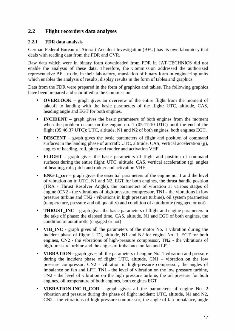
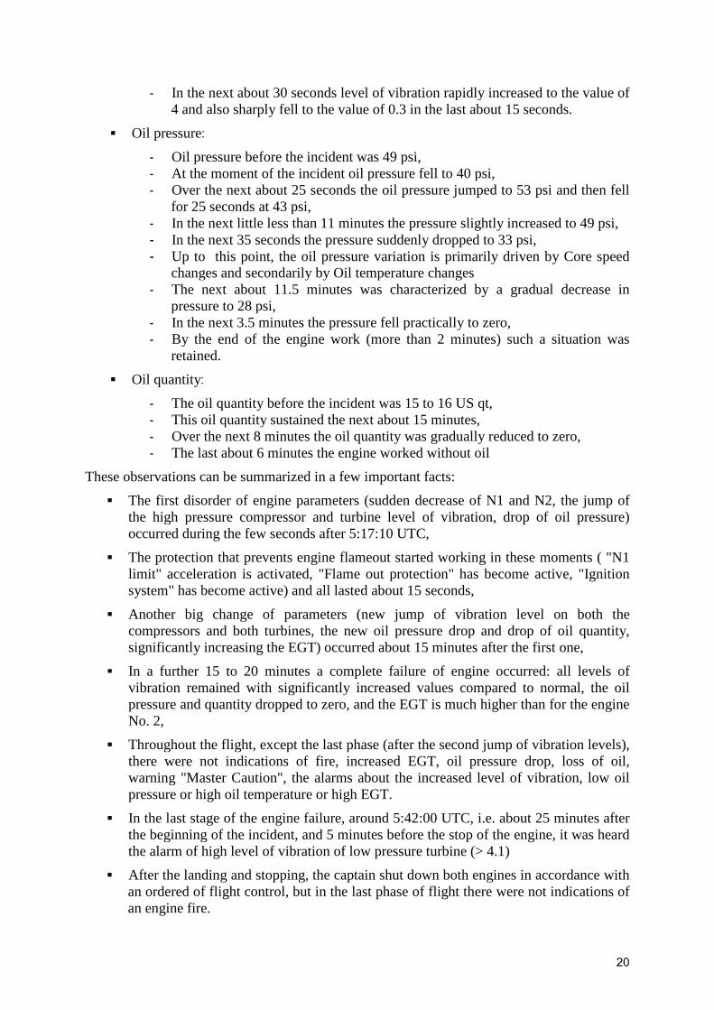
� 55X74281: LPT Shaft Assembly
- LPT shaft was found with heavy wear, chafing and with high metal pick-ups on the painted surface,
- Bearing #4 has been found with multiple damages (inner race destroyed, rollers worn, burnt, deformed and partially missing),
- Bearing No. 4 Rotating Air/Oil Seal heavily worn
Figure 2.5 shows the layout of the assembly of the inner race, rollers and cage, and Figure 2.6 shows the appearance of a very damaged outer race.
Figure 2.5 Figure 2.6
2.3.3 Special analyses of engine components and oil
In this part of the report there are only the basic findings of performed special investigations and analyses of engine components and oils that are listed in paragraph 9. Chapter 1.15.
Otherwise, for each of these analyses there are special reports that, as a reference document [2] - [7], are listed in the document Engine Shop Visit Report (Appendix 7). These documents were available to the Commission, and here are only some conclusions derived from these tests.
� Results of laboratory investigations of the bearing No. 4 can be reduced to the following few facts:
- The bearing was installed in the new engine, i.e. number of hours and number of cycles corresponding to the total number of hours and cycles of the engine,
- Outer race: Spalling area (lg 78 mm) at race way location; Microstructure exhibited fatigue butterflies at spalling area location; Hardness check within specifications; Groove on inner diameter machined by inner back up bearing; No damage due to assembly operation
- Inner race: Rollers path diameter wear with smeared material; Lubrication holes clogged due to shoulders diameter wear; Inner back up bearing diameter wear; FWD seal teeth wear,
- Rollers: Several spalling craters located on outer diameters (no singular spalling); Flat spots located on outer diameter and end wear; Rollers diameters within specifications except one place removed from cage rupture location (diameter decrease 0.2 mm); Rollers length values between 14 and 14.04 mm (specifications 14 ± 0.2 mm); Microstructure didn’t show diameter overheating evidence; Hardness check within specifications; Microstructure OK,
- Cage: Rails and two spacers broken (no singular damage)
Based on the performed analysis it was concluded: bearing failure root cause identified as outer race spalling due to material fatigue.

28
� Lubrication unit and its location on the engine are shown in Figure 2.7.
Figure 2.7
Summary of the investigation:
- Shaft driving quill not broken - “Hard stop” confirmed every 7 revolutions - Main Shaft breakaway torque within CMM limits (except at hard stop) - Teardown: contamination by dark, sticky oil - Dimensional check: most dimensions within limits
Conclusions:
- The Lubrication Unit was running during the event flight (Shaft shear section not broken)
- Pump performances within CMM limits - Dark oil deposit most likely occurred post bearing failure and during the low /
no oil operation
� The analysis of the oil filter showed the presence of particles of various metals and non-metals: tungsten, chromium, nickel, vanadium, manganese, aluminum, molybdenum, iron, titanium, etc. Also, the traces of metal that match the composition of M50 steel (from which the outer race engine bearing No. 4 is made) were found.
� The exploded view of the CMD (detail D in the Figure 2.7) is shown in the Figure 2.8.
Two oil samples were taken for the analysis from the middle chip detector from forward sump. In one of them there were found very large amounts of impurity such as iron, chromium, molybdenum, nickel, vanadium, aluminum, titanium and silicon.
In the second sample there were found exceptionally large amounts of impurity such as iron, nickel and silicon. Viscosity of oil in alert and very high water contamination.

29
Figure 2.8
� A detailed visual and boroscopic inspections of scavenge and supply lines were performed and also the inlet and outlet area of the involved components were checked without abnormal findings. The rotation of Lubrication Unit drive shaft was found very restricted.
Figure 2.9 schematically shows the oil circuit with marked locations on witch oil samples were taken for the analyses during engine disassembling.
Figure 2.9
The samples were visually examined before the more sophisticated analyses. Several samples were light orange, several were dark orange-brown and one sample was a mixture of dark gray oil over colorless, transparent water.
Oil circulation in most engines is very fast, resulting in a homogeneous oil color even though each engine's oil system will have cooler and hotter regions. The color differences in this case might be explained if the noncirculating oil experienced significantly different temperature regimes in the engine after shut down.
Closer visual examination of all the oil samples revealed small, colorless particles in the oil. Sample No. 1 contained much more of this material than other samples. The material was isolated, purified and examined by infrared spectroscopy. The infrared spectrum of the isolated material matched the infrared spectrum of a polydimethyl siloxane polymer. The silicone polymers normally exist in traces in Jet Oil II which was used in this engine’s oil circuit. Тhе oil manufacturers use trace amounts of silicone polymers as antifoaming agents in their jet oils. ExxonMobil can not explain
30
why the oil samples taken from this engine contain excessive amounts of a silicone polymer.
Further analyses showed that in the samples there was no evidence for contamination by jet fuel, phosphate ester hydraulic fluid, landing gear fluid or other common jet engine oil system contaminants.
Most of the oil samples contained about the same amount of iron, nickel and other engine construction elements. The amounts of these metals are higher than is normally seen in oil samples from normally-operating CFM56 engines.
Same samples contained significant amounts of sulfur, calcium, aluminum and sodium – the elements that normally don’t exist in jet oils. The fire fighting foam is believed to be responsible for these unusual elements.
This investigation started with the assumption the tail pipe fire was caused by an oil system contaminant. Most common oil system contaminants usually evaporate or thermally decompose during normal engine operations. The failure to identify specific contaminants does not mean that they were not present; it only means that the contaminants could not be detected at the time the oil sample analysis was performed. The tail pipe fire must have had a cause however oil sample analysis did not explicitly identify a cause related to the oil system.
2.3.4 Conclusions on the basis of engine inspections
After the extensive investigation and analyses of the engine situation which included:
���� Early investigation on the site (in Belgrade),
���� Flight Data Records analysis,
���� Engine and Lubrication Unit shop investigation,
���� Number 4 bearing laboratory examination,
���� Oil samples laboratory analyses and
���� Root Cause Analysis
It is assumed that the event sequence and scenario are as follows:
���� Initial failure of the No. 4 bearing at FL350 (altitude 35000 feet), most likely due to outer race fatigue,
���� Engine oil loss during descent
- Silicon polymer contamination most likely contributed to oil foaming, - Oil foaming induced oil scavenge difficulty, - Oil drained and accumulated into the Aft centerbody - Low Oil Pressure warning condition met when passing 3900 ft - Engine kept operating without oil - Sustained operation with failed bearing (≈30 minutes) and then without oil
(≈ 4 minutes) - Overheated air exiting the bearing sumps
� Fire initiation, most likely in the Aft centerbody
���� Sustained fire leading to Center Vent outlet flame arrestor honeycomb melting
31
���� Initial No. 4 bearing failure combined with silicon contaminated oil (foaming) and sustained operation without oil most likely resulted in drained oil fire
The most difficult fact to explain was the oil loss. No mechanical discrepancy could be found (no broken pipe, no clogged line, no loose fitting reported, no defective oil pump), the only abnormal finding was an unusual contamination of the oil by Silicon polymer, which was reported by Exxon Mobil as likely acting as an oil profoamant, which in turn could have impaired the oil scavenging.
2.4 History of No. 4 bearing failures and taken measures The No 4 bearing is the inter-shaft roller bearing between the High Pressure and Low Pressure rotors and lies within the LPT module at the rear of the engine (Figure 2.1). The inner race, with the rollers and cage, are mounted on the LP shaft and the outer race is mounted in the rear of the HP spool.
It is common to all models of the CFM56 engine and has been, over time, the least reliable of its five principal shaft bearings. The bearing design and manufacturing process has evolved several times in attempts to reduce the number of failures.
The material used in the bearing outer race was changed once to improve bearing life, and the bearing manufacturing process has been improved once. Also, bearings with the original outer race can be reworked with the new outer race. There are three separate bearing manufacturers. Since each manufacturer has unique part numbers for the same design, and there are different part numbers for parts with the original outer race, the new outer race and reworked bearings, then multiple part numbers exist for this bearing, but this does not reflect numerous design changes.
This led to such situation that you can find many different types of this bearing installed in the engines of model CFM56-7B. According to the catalog "Lufthansa Technic - Engine Parts & Accessories Repair CFM56-7B" from the 2010, the types of the bearing differ by the part number. These part numbers are: 305-352-301-0, 305-355-622-0, 305-355-625-0, 305-355-715-0, 305-355-717-0, 305-355-718-0, 305-355-720-0, 335-352-301-0, 335-352-302-0, 335-352-303-0, 335-352-304-0, 335-352-305-0, 340-167-901-0 and 340-167-902-0.
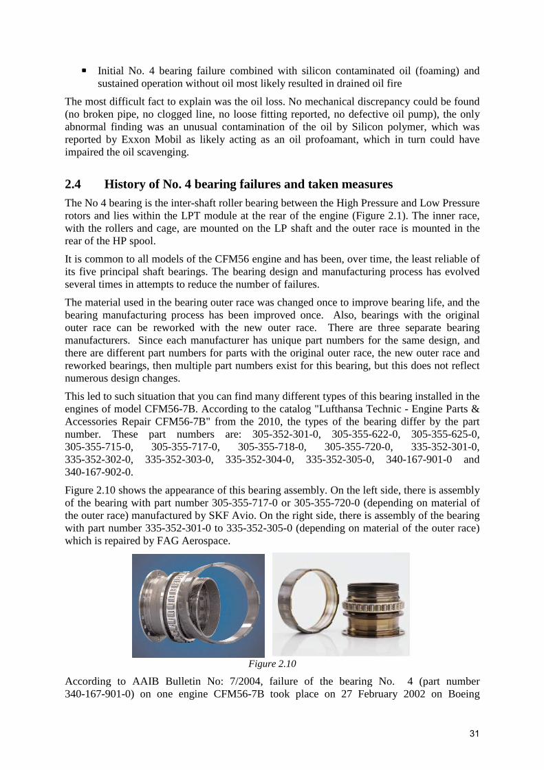
Figure 2.10 shows the appearance of this bearing assembly. On the left side, there is assembly of the bearing with part number 305-355-717-0 or 305-355-720-0 (depending on material of the outer race) manufactured by SKF Avio. On the right side, there is assembly of the bearing with part number 335-352-301-0 to 335-352-305-0 (depending on material of the outer race) which is repaired by FAG Aerospace.
Figure 2.10
According to AAIB Bulletin No: 7/2004, failure of the bearing No. 4 (part number 340-167-901-0) on one engine CFM56-7B took place on 27 February 2002 on Boeing

32
737-8AS, registered EI-CSA, with 117 passengers and 7 crew members in preparing for landing on one of London's airports. Bearing up to that point had 7908 working hours, that was 5485 cycles.
According to same source, failure of the bearing No. 4 (part number 305-355-717-0) on one engine CFM56-5B took place on 21 April 2002 on Airbus A321-211, registered F-GTAF, with 162 passengers and 7 crew members after 3 to 4 minutes after take off from London’s airport Heathrow. Bearing up to that point had 1033 working hours, which was 751 cycles.
Also, according to the same source, between 1998 and April 2002 there were 15 failures of No 4 bearings on CFM56-7B engines, with many more on other CFM56 models. This, although regarded as unsatisfactory, represented less than 1% of the bearing population with a Mean Time Between Failures of 800,000 hours.
At the time of the incidents involving EI - CSA and F - GTAF, according to AAIB Bulletin No: 7/2004, three standards of No 4 bearing remained applicable for the CFM56-7 engine, including the -901 fitted to the engine from EI-CSA and the -717 in second case.
A review of statistics showed that the -901 bearing, although one of the more recently introduced, was performing below the average of all the standards of this bearing and, as a result, it was decided to discontinue production of this part number also and withdraw stocks.
The failed bearing fitted to F-GTAF was a - 717 standard part number, which had one of the best service records and which has been in production since 1986 by SKF.
It was evident, from data supplied by the engine manufacturer, that more than 80% of failures occurred within 6,000 hours of installation, of which more than half failed within 2,000 hours. The data also showed that there was little difference in the failure rates in new engines as compared to those which had been overhauled. From this, the manufacturer inferred that the bearing was particularly prone to mishandling or damage during installation, or during module splitting and refitting at engine workshop visits, and could be particularly susceptible to contamination or manufacturing variability.
The findings of investigations, by the manufacturer, into previous failures supported this and also indicated that the predominant primary cause of failure was spalling of the bearing outer race. To counter possible workshop mistreatment of the bearing, the manufacturer had instituted changes to Maintenance Manual procedures and working practices, emphasizing the sensitivity of the bearings to mishandling and corrosion. Since the introduction of these changes an improvement in the reliability of No. 4 bearings has been observed.
In a development of the bearing, the manufacturer changed the material and surface treatment of the bearing outer race in order to overcome the potential spalling problem. For example, bearings manufacturer SKF Avio, according to its catalog, on the basis of the bearing with part number 305-355-717-0, where the outer race has been subjected to excessive stresses resulting in degradation of the outer race, developed an upgraded bearing with part number 305-355-718-0 for new made bearings and 305-355-720-0 for outer race reworked bearings. This improved bearing has the outer race, instead of material M50 or M50NiL, made of material 32CDV13 with subsequent deep nitriding.
On the other hand, the company FAG Aerospace GmbH & Co. KG, according to its catalog, performs repairing of bearing No. 4 with part numbers 335-352-301-0 up -303-0 by replacing the outer race, cage and rollers with completely new components. Thereby, the outer race is made of material M50 with nitriding. During repair process the outer race can be made of the better material thus obtained bearings with part numbers 335-352-304-0 and -305-0.

33
In another endeavor to reduce the in-flight shutdown rate, the manufacturer had developed a portable vibration monitoring tool to detect incipient failures of No 4 bearing, for use both in test-cells and during ground runs. This has proved effective at identifying No 4 bearings with pre-failure conditions or damage believed likely to develop into complete failures.
The engine manufacturer, CFM International, together with Boeing and Vibrometer have jointly developed an advanced version of the AVM system, for CFM 56 powered versions of the Boeing 737, using the existing engine mounted accelerometers. This, in addition to the functions already performed by the current AVM system, specifically monitors the health of the No 4 bearing to give maintenance engineers information that a degraded bearing state may exist.

34
III CONCLUSIONS
3.1 Conclusions related to the emergency landing of aircraft On the basis of the analyses of relevant information, reports and statements of all services that were directly involved in this extraordinary event (ACC, TCC, firefighting and rescue service and other airport services), the Commission makes the following conclusions:
1. The crew of the aircraft D-AXLF reasonably and in the prescribed manner declared an Emergency, immediately upon entering the jurisdiction of ACC Belgrade.
2. ACC Belgrade immediately took all necessary actions and procedures providing an emergency landing for the aircraft in danger at the airport "Nikola Tesla".
3. APP Belgrade duly took all actions and procedures to provide assistance in securing the emergency approach and landing of the aircraft.
4. TWR Belgrade duly took all actions and procedures to provide an emergency landing the aircraft in danger and the involvement of firefighting and rescue services in the firefighting, evacuation and rescue of passengers and crew members after landing.
5. PIC performed all given instructions so that the entire operation was carried out without consequences for passengers and crew of the aircraft.
6. Action of firefighting, evacuation and rescue of passengers and crew members was carried out in accordance with ICAO standards and the usual procedure.
7. All airport services (firefighting and rescue service, police, medical service, ground handling service) performed all their tasks very professionally, following the procedures stipulated in the Plan for Emergency Situations. This fact contributed that during the evacuation and rescue of passengers and crew members nobody was hurt.
3.2 Conclusions related to the engine shut-down Based on insight into the results of performed analysis and testing of components, sub-assemblies and engine parts, engine modules and working fluid (fuel and oil) the Commission makes the following conclusions:
1. On the altitude 35,000 feet (FL350) the failure of No. 4 bearing (part number 305-355-717-0, serial number DA855449) occurred, probably due to fatigue of the bearing outer race material, which led to the race spalling, and then to the disintegration of the entire bearing assembly.
2. According to available data, this bearing has not been changed, i.e. it worked a total of 31,045 hours and 11,250 cycles over more than 20 years.
3. This aircraft has a standard AVM system which does not provide insight into the health of No. 4 bearing.
4. Due to the disturbed suspension system of the low and high pressure shafts and possible aggravating factors described in the next sections, the following occurred: increasing of the level of their vibration, loss of oil quantity and pressure, EGT and disorder of other engine parameters.
5. The loss of oil was most probably contributed by the silicone contamination of oil, which led to oil’s foaming causing difficulties in the oil scavenge of engine. Oil drained and accumulated in the the Aft centerbody.
35
6. Low Oil Pressure warning condition met when passing 3900 ft and after that the engine continued to work without oil.
7. Working of the engine with the failed bearing No. 4 lasted about 30 minutes, and the work without oil about 4 minutes.
8. Working of the engine in these conditions caused significant damage of other engine parts.
9. The tail pipe fire was the most probably caused due to ignition of drained oil due to the high temperature of the air discharged into the centerbody when operating under the above conditions.
3.3 Conclusions related to nature of incident Based on consideration of all available facts the Commission makes the following conclusions:
1. According to the technical aspect of the event, the consequences caused by it, and even more by what the consequences it could cause depending on the way it is managed (serious injury or even death of passengers or crew members) this incident is very important from the aspect of safety in civil aviation.
2. Given the seriousness of the event and consequences that might occur this event should be categorized as a serious incident.
3. If you keep in mind that failure of No. 4 bearing is still happening in operation, although some measures have been indicated to prevent or control this, solving the problem should be the fruit of joint efforts of engine manufacturers, aircraft manufacturers, the users of these aircrafts, the manufacturers of bearings and other interested parties.
4. The fact to which attention should be paid is that the failure of No. 4 bearing occurs with the small number as well as the much larger number of hours and cycles of work. For example, in the incident of the aircraft registered F-GTAF failure of this bearing occurred after only 1033 hours of work, or 751 cycles and in this case exactly the same type of bearing (part number 305-355-717-0) suffered the failure much later.
IV CAUSE OF SERIOUS INCIDENT
On the basis of all, in this Report mentioned, research, testing and analyses the Commission considers that the main cause of the incident, i.e. in flight shut down of the engine No. 1 was complete failure of engine bearing No.4 which has been located in a LPT Shaft Assembly.
Failure of the bearing caused the deterioration of working conditions of the engine and later led to engine in flight shut down.
36
V SAFETY RECOMMENDATIONS
To avoid that in future there is an accident or incidents for the same reason, the Commission recommends the following safety recommendations:
1. It is recommended that the aircraft manufacturer, the Federal Aviation Administration (FAA) and European Aviation Safety Agency (EASA) should be informed about this serious incident.
2. It is recommended that the engine manufacturers, the Federal Aviation Administration (FAA) and European Aviation Safety Agency (EASA) should be informed about this serious incident.
3. It is recommended that the engine manufacturer should consider the possibility, for all engines in operation, that during the next engine shop visit, if necessary, existing bearing No 4 be replaced with the bearing made of upgraded materials.
4. It is recommended that the manufacturer of engines and manufacturer of aircrafts on which these engines have been installed to continue refining the system for monitoring the correctness of bearings No. 4 during the flight in order to determine its deteriorating condition on time.
5. In order to prevent erasing of recordings from CVR it is recommended that competent authorities prohibit connection of external power supply to the aircraft until downloading data from CVR.
6. It is recommended that in case of detection of silicon polymer contamination or oil foaming finding during routine maintenance activity the operator or maintenance provider replaces the suspect oil and flush the oil system.
VI DIFFERENT OPINIONS
There are not different opinions of any member of the the Commission.

37
LIST OF APPENDIXES
1. Appendix 1 – AIRCRAFT SURVEY REPORT
2. Appendix 2 – Aircraft damages (photos)
3. Appendix 3 – FDR diagrams
4. Appendix 4 – CVR-Script
5. Appendix 5 – ESN 874281 preliminary findings Rev. 2b
6. Appendix 6 – ESN 874281 BSI report
7. Appendix 7 - Shop-Report Engine 874281
Appendixes are provided as separate documents.