AIRCRAFT SERIOUS INCIDENT INVESTIGATION REPORT · aircraft serious incident investigation report...
30
AI2011-5 AIRCRAFT SERIOUS INCIDENT INVESTIGATION REPORT NIPPON CARGO AIRLINES CO., LTD. J A 0 1 K Z August 26, 2011 Japan Transport Safety Board
Transcript of AIRCRAFT SERIOUS INCIDENT INVESTIGATION REPORT · aircraft serious incident investigation report...
AI2011-5
AIRCRAFT SERIOUS INCIDENT
INVESTIGATION REPORT
NIPPON CARGO AIRLINES CO., LTD.
J A 0 1 K Z
August 26, 2011
Japan Transport Safety Board
The objective of the investigation conducted by the Japan Transport Safety Board in accordance
with the Act for Establishment of the Japan Transport Safety Board (and with Annex 13 to the
Convention on International Civil Aviation) is to prevent future accidents and incidents. It is not the
purpose of the investigation to apportion blame or liability.
Norihiro Goto
Chairman,
Japan Transport Safety Board
Note:
This report is a translation of the Japanese original investigation report. The text in Japanese shall
prevail in the interpretation of the report.

AIRCRAFT SERIOUS INCIDENT INVESTIGATION REPORT
NIPPON CARGO AIRLINES CO., LTD. BOEING 747-400F, JA01KZ
ABOUT 140 FEET OVER RUNWAY A OF NARITA INTERNATIONAL AIRPORT, JAPAN
AT ABOUT 21:54 JST, JUNE 11, 2010
August 5, 2011
Adopted by the Japan Transport Safety Board Chairman Norihiro Goto Member Shinsuke Endoh Member Toshiyuki Ishikawa Member Yuki Shuto Member Toshiaki Shinagawa
The following abbreviations are used in this report:
BSI : Borescope Inspection CVR : Cockpit Voice Recorder DFDR : Digital Flight Data Recorder DSR142 : Directionally Solidified RenéTM 142 EGT : Exhaust Gas Temperature EICAS : Engine Indicating and Crew Alerting System FF : Fuel Flow HPC : High Pressure Compressor HPT : High Pressure Turbine HPTR : High Pressure Turbine Rotor LPC : Low Pressure Compressor LPT : Low Pressure Turbine N1 : Low Pressure Compressor Speed (Fan Speed) N2 : High Pressure Compressor Speed NGV : Nozzle Guide Vane PF : Pilot Flying PM : Pilot Monitoring RN5 : RenéTM N5 S/B : Service Bulletin TBC : Thermal Barrier Coating TRF : Turbine Rear Frame V1 : Takeoff decision speed V2 : Takeoff safety speed VR : Rotation speed VSV : Variable Stator Vane
RenéTM denotes a nickel-based heat-resistant alloy developed by General Electric.

1
1. PROCESS AND PROGRESS OF THE INVESTIGATION 1.1 Summary of the Serious Incident
The occurrence covered by this report falls under the category of “Damage of engine (limited to a major damage occurred inside the engine)” as stipulated in Clause 6, Article 166-4 of the Civil Aeronautics Regulations of Japan, and is classified as an aircraft serious incident.
On June 11 (Friday), 2010, a Boeing 747-400F, registered JA01KZ, operated by Nippon Cargo Airlines Co., Ltd., took off from Narita International Airport as a scheduled flight 166 (a cargo flight) of the company for Anchorage International Airport, the United States of America. At about 21:54 Japan Standard Time (JST: UTC+ 9hr, unless otherwise stated all times are indicated in JST on a 24-houre clock) just after the takeoff, an abnormal noise was heard from one of its engines and an instrument indicated a No.1 engine failure. Therefore, the flight crew shut down the No.1 engine after climbing to an altitude of 7,000 feet. After jettisoning its fuel, the aircraft turned back and landed at Narita International Airport at 23:08.
There were three persons on board, consisting of the Captain, one crewmember and an employee of the company, but no one was injured. 1.2 Outline of the Serious Incident Investigation 1.2.1 Investigation Organization
On June 14, 2010, the Japan Transport Safety Board designated an investigator-in-charge and another investigator to investigate this serious incident.
1.2.2 Representatives from Foreign Authorities
An accredited representative and an adviser of the United States of America, as the State of Design and Manufacture of the aircraft involved in this serious incident, participated in the investigation.
1.2.3 Implementation of the Investigation
June 15, 2010 Aircraft and engine examinations and flight crew interviews
June 16, 2010 Flight crew interviews June 28 to 30, 2010 Teardown inspection of the engine at a facility designated
by the engine manufacturer in Taiwan July to September, 2010 A detailed examination of stage 1 high pressure turbine
blades at a laboratory of the engine manufacturer in the United States of America
1.2.4 Provision of Factual Information to the Civil Aviation Bureau, the Ministry of Land, Infrastructure, Transport and Tourism
On July 9, 2010, factual information about the condition of damage to the inside of the engine was provided to the Civil Aviation Bureau of the Ministry of Land, Infrastructure, Transport and Tourism.
1.2.5 Comment from Parties Relevant to the Cause of the Serious Incident
Comments were invited from parties relevant to the cause of the serious incident.

2
1.2.6 Comments from the Participating State Comments on the draft report were invited from the participating State.
2. FACTUAL INFORMATION 2.1 History of the Flight
At 21:54 on June 11, 2010, a Boeing 747-400F, registered JA01KZ (hereinafter referred to as “the Aircraft”), operated by Nippon Cargo Airlines Co., Ltd. (hereinafter referred to as “the Company”), took off from runway 16R (hereinafter referred to as “16R”) of Narita International Airport (hereinafter referred to as “the Airport”) as a scheduled flight 166 of the Company for Anchorage International Airport, the United States of America.
The outline of the flight plan was as follows: Flight rules: Instrument flight rules (IFR) Departure aerodrome: Narita International Airport Estimated off-block time: 21:40 Cruising speed: 495kt Cruising altitude: Flight Level (FL) 310 Route: GIRAF (reporting point) – Y808 (RNAV route) – (The
rest is omitted) Destination aerodrome: Anchorage International Airport Estimated flight time: 6 h and 34 min
At the time of the serious incident, in the cockpit of the Aircraft, the Pilot in Command (PIC) was in the left seat as the PF (pilot flying: pilot mainly in charge of flying) and the First Officer (FO) was in the right seat as the PM (pilot monitoring: pilot mainly in charge of duties other than flying).
The history of the flight up to the time of the serious incident is summarized below, based on the records of the digital flight data recorder (hereinafter referred to as “the DFDR”), ATC communication records and the statements of the flight crewmembers.
2.1.1 History of the Flight based on the DFDR Records and ATC Communication Records
21:52:28 The Narita Airport Traffic Control Tower (hereinafter referred to as “the Tower”) issued a take-off clearance for the Aircraft.
21:52:42 The throttle levers for all the four engines were advanced while the Aircraft was on the runway The low pressure compressor (LPC) rotation speed (hereinafter referred to as “N1”), the high pressure compressor (HPC) rotation speed (hereinafter referred to as “N2”) and the fuel flow (hereinafter referred to as “FF”) gradually increased for all the engines.
21:53:41 The Aircraft lifted off at an airspeed of about 190 knots. 21:53:48 N1 and N2 for No.1 engine declined fast at an altitude of about 140 feet
and at an airspeed of about 200 knots. The exhaust gas temperature (hereinafter referred to as “EGT”) temporarily went up, but it gradually went down later along with a decline in FF.
21:53:50 The vibration of No.1 engine increased to a maximum value of 5 units. The heading of the Aircraft veered to the left by about 6 degrees, but the

3
veering was corrected later. 21:53:57 The Tower instructed the Aircraft to contact the Tokyo Departure Control
(hereinafter referred to as “the Departure”). 21:53:58 The autopilot was engaged. 21:54:03 FO reported the occurrence of an engine failure to the Tower. 21:54:40 FO reported the occurrence of an engine failure to the Departure. FO also
requested for a clearance for climbing to an altitude of 7,000 feet and reported to the Departure that it takes about an hour to jettison fuel.
Past 21:59 The Aircraft reached an altitude of about 7,000 feet and maintained a level flight.
22:00:36 The throttle lever for No.1 engine was retarded to the idle position. 22:00:45 The fuel control switch for No.1 engine was shifted to the Cut-off position. 23:08 The Aircraft landed at 16R of the Airport.
There was no record of a master warning activated during the flight. 2.1.2 Statements of Crewmembers (1) PIC
I was sitting in the left seat and FO in the right seat. Another person was on aboard the Aircraft, but he was not in the cockpit. The takeoff weight of the Aircraft was heavier than usual for this flight. The Aircraft left an apron at 21:39, but I felt nothing unusual with the engines.
While the Aircraft was in takeoff rolling, EICAS*1 displayed no message of failure. I performed a nose-up operation and when the Aircraft lifted off and started climbing, I heard a big abnormal noise and a message was indicated on EICAS that failure has occurred with No.1 engine.
I continued climbing while leaving the situation as it was and then, I shut down No.1 engine at an altitude of about 7,000 feet. I decided to return to Narita Airport and flew toward the reporting point of VENUS under the controller’s instructions to jettison fuel. While receiving radar vector at an altitude of 7,000 feet, the Aircraft jettisoned about 150,000 pounds of fuel in about 45 minutes and after that, the Aircraft landed on16R of the Airport at 23:08. The Aircraft has four engines and despite the failure which occurred with one engine, the Aircraft was fully controllable. Therefore, I did not declare an emergency.
(2) FO When we started the engines, these were all normal. We found no abnormality when we
performed the checklist. After the start of the takeoff rolling, when I called a V1 (Takeoff decision speed) at
around a speed of 155 knots, the indications of the engine-related instruments were normal. The nose of the Aircraft was pulled up at a VR (Rotation speed) of 170 knots, and I called a V2 (Takeoff safety speed) at a speed of 180 knots. After confirming the positive climb rate, I raised the landing gear lever under PIC’s instructions. Just after that, I heard a boom sound and the N1 and EGT readings for No.1 engine clearly declined.
I think the engine failure occurred at a pressure altitude of about 300 feet over the runway, but I cannot remember the altitude exactly. PIC continued to climb straight and
*1 EICAS means an integrated system designed to display the operational conditions of the engines and part of
other systems and notify the pilot of the occurrence of abnormalities by visual and auditory means

4
engaged the autopilot. Because I saw a message of No.1 engine failure on the EICAS display, I called “Engine Failure No.1.”
When we received instructions from the Tower to contact the Departure, I reported to the Tower of the occurrence of the engine failure. Later, I changed the radio frequency and also reported to the Departure of the occurrence of the engine failure. I requested the Departure to climb to an altitude of 7,000 feet under PIC’s instructions.
We flew to VENUS to jettison fuel and performed a checklist for “Engine Failure and Shutdown”, “After Takeoff” and “Fuel Jettison”. While we came close to VENUS, we started jettisoning the fuel and requested the controller for radar vector.
After the jettisoning of fuel, we returned to the Airport and landed on 16R normally with the remaining three engines.
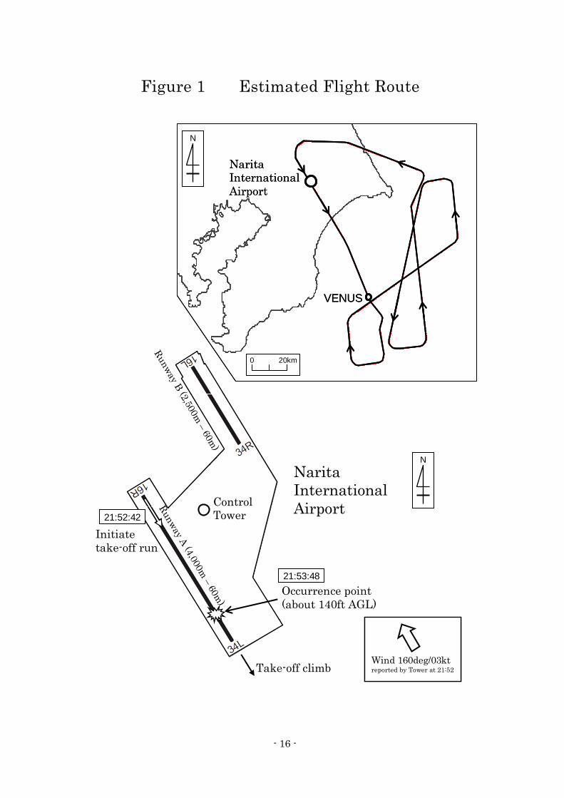
This serious incident occurred at about 21:54 at an altitude of about 140 feet over runway A of
the Airport (around Latitude 35˚44’ 54” N, Longitude 140˚23’12” E). (See Figure 1 Estimated Flight Route, Figure 2 DFDR Records, Photo 1 Serious Incident Aircraft) 2.2 Injuries to Persons
No one was injured in the serious incident. 2.3 Damage to the Aircraft 2.3.1 Extent of Damage
The inside of No.1 engine was substantially damaged, but there was no other damage to the Aircraft. 2.3.2 Damaged Condition of No.1 Engine
A visual inspection and a borescope inspection (hereinafter referred to as “BSI”) revealed that damaged condition of No.1 engine was as follows: (1) There were no signs of foreign object debris (FOD) ingested from outside on the fan blades. (2) No abnormality was detected in the compressor and the combustion chamber. (3) The trailing edge of the nozzle guide vane (hereinafter referred to as “NGV”), located at the
way out of the combustion chamber, was found partially damaged. (4) Four of the 80 stage 1 high pressure turbine (HPT) blades were found broken from the root,
and all other blades had also been damaged. (5) The 74 stage 2 HPT blades were all damaged. (6) The low pressure rotor could not be rotated. Several low pressure turbine (LPT) blades had
been broken in a section which can be observed near the BSI port. (7) Damage was found in the stage 5 LPT vane and the stage 5 LPT blades behind it, which can
be seen from the back of the engine. (8) Numerous fine pieces of metal had been left in the turbine rear frame (hereinafter referred
to as “TRF”). 2.4 Personnel Information
(1) PIC Male, Age 59 Airline Transport Pilot Certificate (Airplane) July 28, 1987

5
Type rating for B747-400 June 23, 2003 Class 1 Aviation Medical Certificate Validity July 13, 2010 Total flight time 16,274 h 36 min Flight time in the last 30 days 11 h 46 min Total flight time on the type of aircraft 3,079 h 00 min Flight time in the last 30 days on the type of aircraft 11 h 46 min (2)FO Male, Age 30 Airline Transport Pilot Certificate (Airplane) May 9, 2006 Type rating for B747-400 March 27, 2008 Class 1 Aviation Medical Certificate Validity October 15, 2010 Total flight time 5,043 h 53 min Flight time in the last 30 days 48 h 02 min Total flight time on the type of aircraft 835 h 30 min Flight time in the last 30 days on the type of aircraft 48 h 02 min
2.5 Aircraft Information 2.5.1 Aircraft
Type Boeing 747-400F Serial number 34016 Date of manufacture May 16, 2005 Certificate of airworthiness DAI-TOU-21-145 Validity June 30, 2010 Category of airworthiness Airplane, Transport T Total flight time 20,730 h 59 min Flight time since last periodical check (C03 check on April 25, 2009) 4,807 h 50 min
(See Figure 3 Three Angle View of Boeing 747-400F)
2.5.2 Engine Model General Electric CF6-80C2B1F No.1 Engine No.2 Engine Serial Number 706704 706768 Date of manufacture April 26, 2005 December 19, 2006 Total time 17,006 h 20 min 11,312 h 22 min Total cycles 3,126 cycles 2,271 cycles No.3 Engine No.4 Engine Serial Number 706810 706887 Date of manufacture January 20, 2007 October 30, 2007 Total time 10,152 h 44 min 6,672 h 08 min Total cycles 2,072 cycles 1,373 cycles (See Figure 4 CF6-80C2 Engine, Photo 2 Dismounted No.1 Engine)
2.5.3 History of No.1 Engine
6
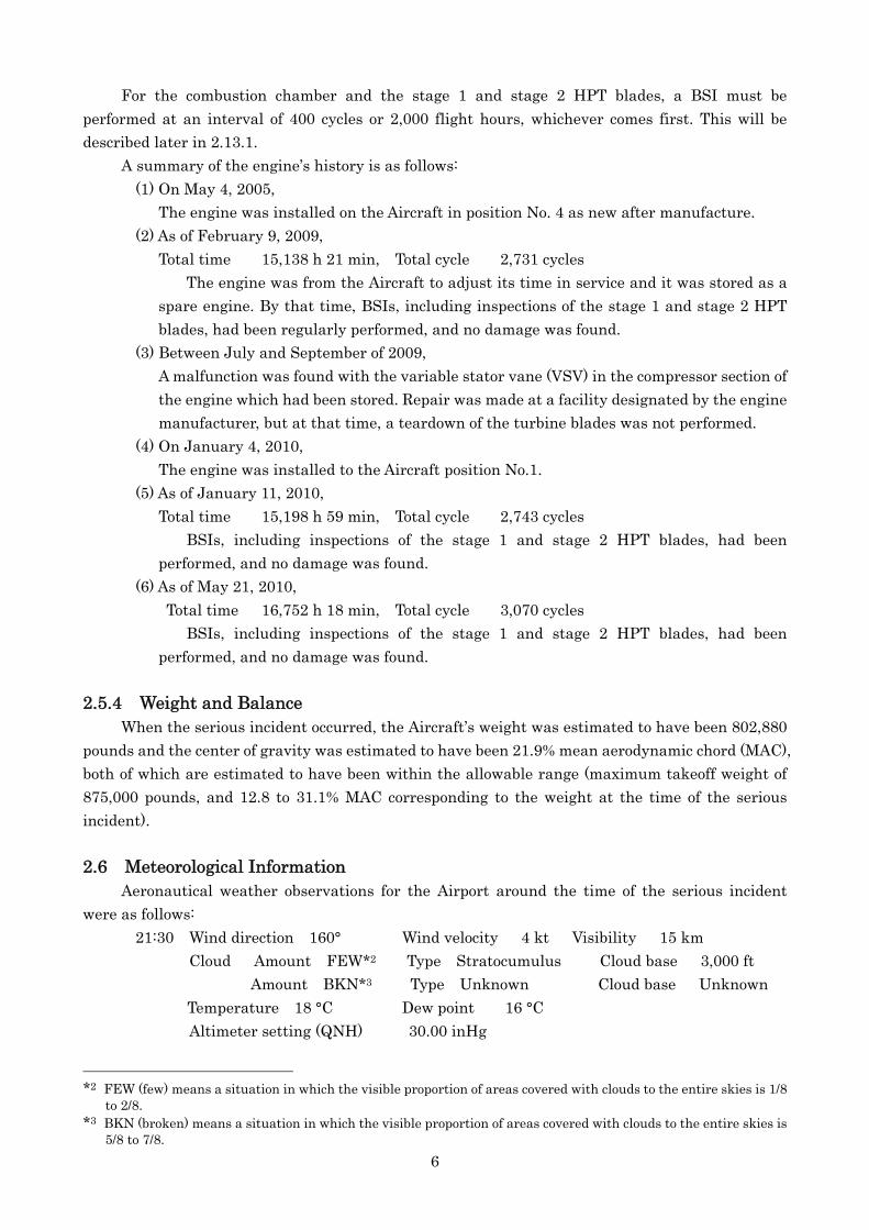
For the combustion chamber and the stage 1 and stage 2 HPT blades, a BSI must be performed at an interval of 400 cycles or 2,000 flight hours, whichever comes first. This will be described later in 2.13.1.
A summary of the engine’s history is as follows: (1) On May 4, 2005,
The engine was installed on the Aircraft in position No. 4 as new after manufacture. (2) As of February 9, 2009,
Total time 15,138 h 21 min, Total cycle 2,731 cycles The engine was from the Aircraft to adjust its time in service and it was stored as a
spare engine. By that time, BSIs, including inspections of the stage 1 and stage 2 HPT blades, had been regularly performed, and no damage was found.
(3) Between July and September of 2009, A malfunction was found with the variable stator vane (VSV) in the compressor section of the engine which had been stored. Repair was made at a facility designated by the engine manufacturer, but at that time, a teardown of the turbine blades was not performed.
(4) On January 4, 2010, The engine was installed to the Aircraft position No.1.
(5) As of January 11, 2010, Total time 15,198 h 59 min, Total cycle 2,743 cycles
BSIs, including inspections of the stage 1 and stage 2 HPT blades, had been performed, and no damage was found.
(6) As of May 21, 2010, Total time 16,752 h 18 min, Total cycle 3,070 cycles
BSIs, including inspections of the stage 1 and stage 2 HPT blades, had been performed, and no damage was found.
2.5.4 Weight and Balance
When the serious incident occurred, the Aircraft’s weight was estimated to have been 802,880 pounds and the center of gravity was estimated to have been 21.9% mean aerodynamic chord (MAC), both of which are estimated to have been within the allowable range (maximum takeoff weight of 875,000 pounds, and 12.8 to 31.1% MAC corresponding to the weight at the time of the serious incident).
2.6 Meteorological Information
Aeronautical weather observations for the Airport around the time of the serious incident were as follows:
21:30 Wind direction 160° Wind velocity 4 kt Visibility 15 km Cloud Amount FEW*2 Type Stratocumulus Cloud base 3,000 ft Amount BKN*3 Type Unknown Cloud base Unknown
Temperature 18 °C Dew point 16 °C Altimeter setting (QNH) 30.00 inHg
*2 FEW (few) means a situation in which the visible proportion of areas covered with clouds to the entire skies is 1/8
to 2/8. *3 BKN (broken) means a situation in which the visible proportion of areas covered with clouds to the entire skies is
5/8 to 7/8.
7
22:00 Wind direction 150° Wind velocity 3 kt Visibility 15 km Cloud Amount FEW Type Stratocumulus Cloud base 3,000 ft
Amount BKN Type Unknown Cloud base Unknown Temperature 18 °C Dew point 16 °C Altimeter setting (QNH) 30.00 inHg
2.7 Information on DFDR and Cockpit Voice Recorder The Aircraft was equipped with a DFDR (part number: 980-4700-042) made by Honeywell of
United States of America and a cockpit voice recorder (hereinafter referred to as “the CVR", part number: 2100-1020-00) made by L-3 Communications of United States of America. The DFDR retained data at the time of the serious incident, but CVR did not retain data at the time of the serious incident because the data was overwritten. The time was determined by correlating the DFDR recorded VHF transmission keying signals with the NTT (Nippon Telegraph and Telephone Corporation) speaking clock recorded on the ATC communication records.
2.8 Information on the Serious Incident Site
The Airport has an elevation of 135 feet and has two runways—runway A (16R/34L) with a length of 4,000 meters and a width of 60 meters to the southwestern side and runway B (16L/34R) with a length of 2,500 meters and a width of 60 meters to the northeastern side.
Runway checks were made just after the occurrence of the serious incident and after the Aircraft’s landing, but no broken pieces of the engine or the like were found.
Later, on June 18 and June 21, 2010, three metal pieces as large as about 2 centimeters were found under a takeoff course of 16R about 3 kilometers south of runway A. There was no report of damage caused with the metal pieces.
2.9 Service Bulletins Related to Stage 1 HPT Blades
Following are excerpts from service bulletins (hereinafter referred to as “S/B”) issued by the engine manufacturer regarding the stage 1 HPT blades (part number: 1538M90P12) which had been installed in the No.1 engine of the Aircraft: (1) S/B 72-721, issued on December 21, 1993 Compliance level: Do at customer convenience. The S/B concerned the release of stage 1 HPT blades (part number: 1538M90P12) made
from a DSR 142 material with Thermal Barrier Coating (TBC) applied on the outside surface of the blade airfoil.
(2) S/B 72-1090, issued on March 19, 2003 Compliance level: GE recommends you do at customer option. The S/B concerned the release of new stage 1 HPT blades (part number: 1639M70P11)
made from a single crystal RN5 material. It said the supply of part numbers: 1538M90P11 and 1538M90P12 will be continued.
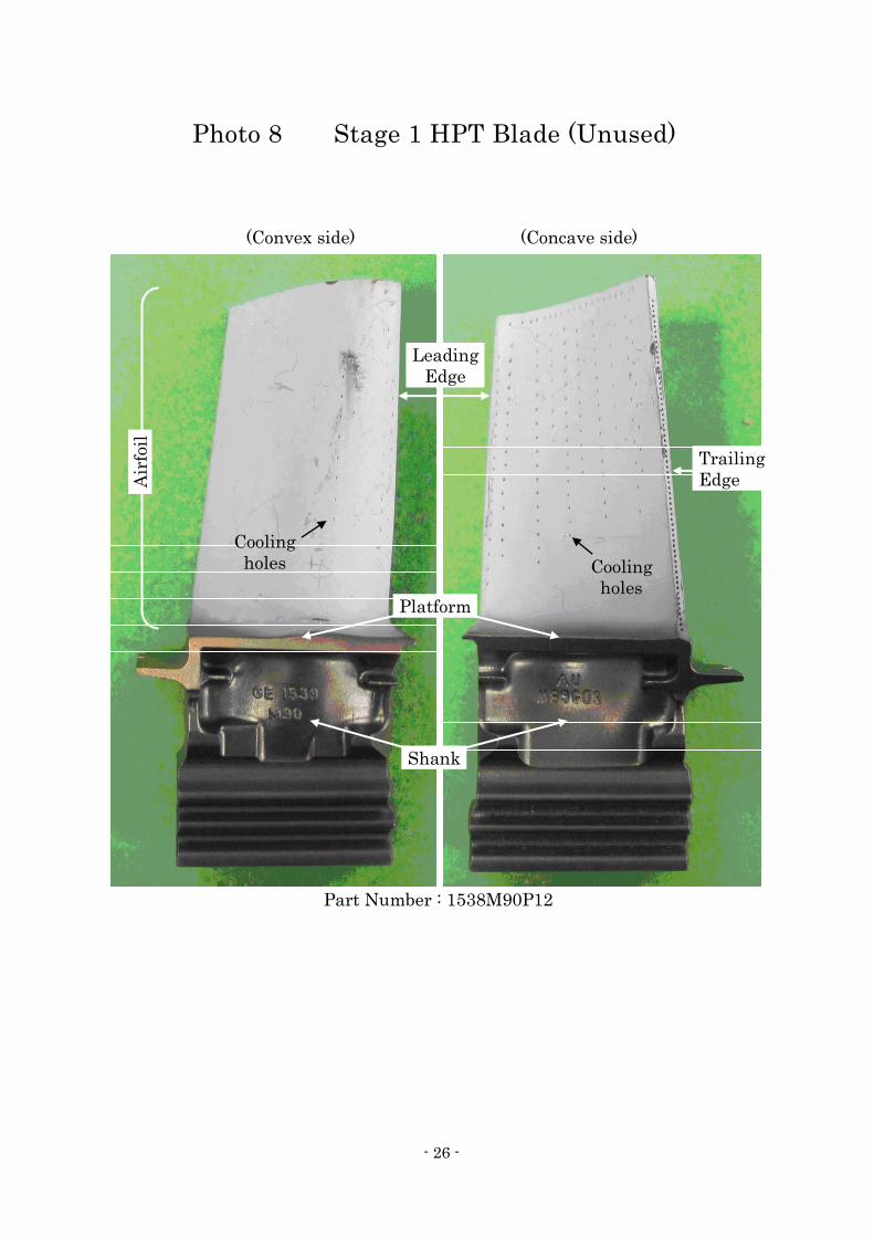
(3) S/B 72-1269, issued on August 23, 2007 Compliance level: GE recommends that you do this Service Bulletin when the stage 1
HPTR blades are routed for repair The S/B concerned added protective coating against type II hot corrosion (to be described
later in 2.13.3) on the shank area (See Photo 8) below the platform of the stage 1 HPT

8
blade (part number: 1538M90P12). (4) S/B 72-1288, issued on May 8, 2008
Compliance level: GE recommends that you do this Service Bulletin at customer's convenience.
The S/B concerned the release of new stage 1 HPT blades (part numbers: 1538M90P18 and 1538M90P19) made of DSR142 material with an improved shape for the tip of the blades and vapor chromide coating applied to the shank area below the platform.
(5) S/B 72-1296, issued on May 8, 2008 Compliance level: GE recommends that you do this Service Bulletin at customer's
convenience. The S/B concerned the release of new stage 1 HPT blades (part number: 1639M70P17) as
a single crystal RN5 material with an improved shape for the tip of the blades and vapor chromide coating applied to the shank area below the platform.
2.10 Engine Maintenance Activities
According to the Company, the engine maintenance activities were as follows: The Company has concluded a comprehensive maintenance contract with the engine
manufacturer. This includes the collection and analysis of engine-related data. No clear shift in the trend which may indicate abnormalities in the data about the engine was shown since January 2010 when it was installed with the Aircraft as its No.1 engine.
The Company has regularly performed BSIs on the combustion chamber and the HPT blades in accordance with the maintenance manual, but no damage was found with the engine.
The Company was aware of S/B 72-1269 which recommended adding a corrosion protective coating on the shank area of the stage 1 HPT blades. In accordance with its compliance level, the Company planned to perform the S/B when the next overhaul will be made for the engine.
The Company received the Aircraft in June 2005. The Aircraft has operated mainly among cities in Asia, Europe and North America for about six years. There was no inclination to a specific area in its operations
2.11 Engine Data Left on DFDR
According to the records retained on the DFDR about the preceding seven takeoffs before the occurrence of this serious incident, there was no clear difference from engine to engine in the N1, the N2, the FF and the engine vibration value until just before this serious incident.
2.12 Tests and Researches for Fact-Finding 2.12.1 Teardown Inspection of Engine
For the investigation of this serious incident, a teardown inspection of No.1 engine of the Aircraft was performed at a facility designated by the engine manufacturer. The result was as follows:
(1) There were no signs of FOD ingested into the fan. The high pressure rotor could be rotated, but the low pressure rotor did not rotate
because many metal pieces had got caught in the tips of the stage 5 LPT blades. (2) Contact wear was noted on the HPC rotor and part of the stator case which has 14 stages
in total. There were traces of contact wear on the tips of all HPC blades and HPC vanes. (3) NGV had been partially broken with the trailing edge of most of the vanes damaged.
9
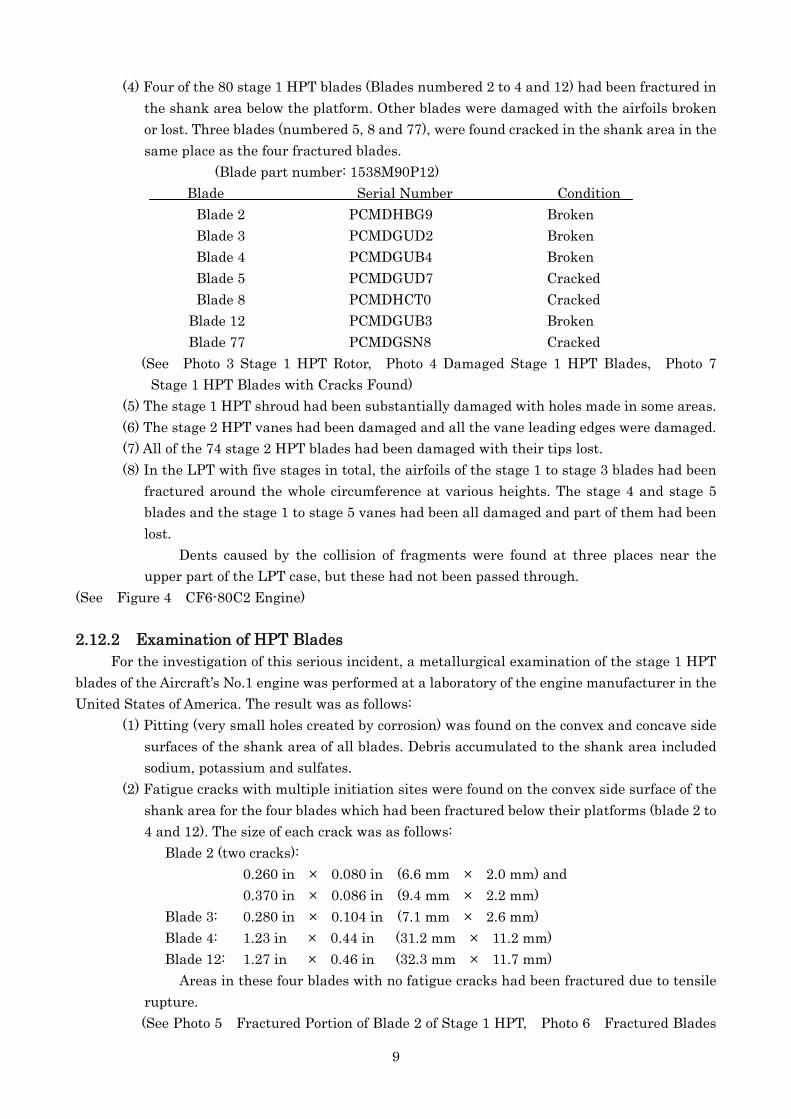
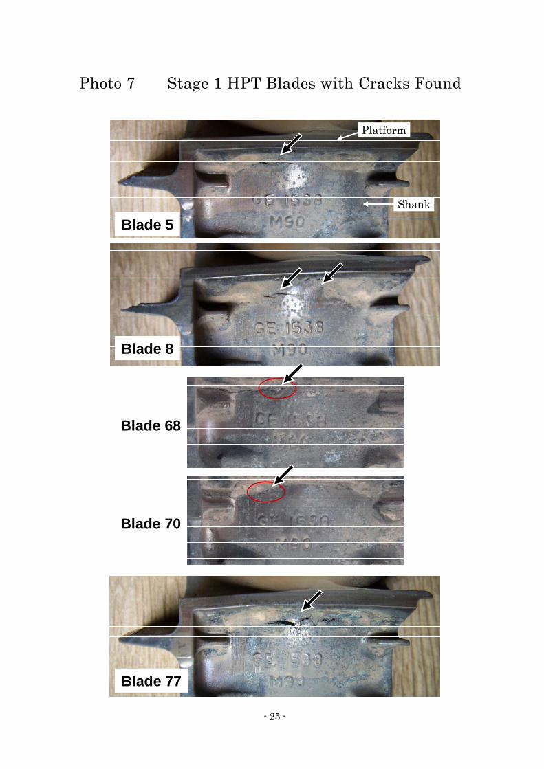
(4) Four of the 80 stage 1 HPT blades (Blades numbered 2 to 4 and 12) had been fractured in the shank area below the platform. Other blades were damaged with the airfoils broken or lost. Three blades (numbered 5, 8 and 77), were found cracked in the shank area in the same place as the four fractured blades.
(Blade part number: 1538M90P12) Blade Serial Number Condition
Blade 2 PCMDHBG9 Broken Blade 3 PCMDGUD2 Broken Blade 4 PCMDGUB4 Broken Blade 5 PCMDGUD7 Cracked Blade 8 PCMDHCT0 Cracked Blade 12 PCMDGUB3 Broken Blade 77 PCMDGSN8 Cracked (See Photo 3 Stage 1 HPT Rotor, Photo 4 Damaged Stage 1 HPT Blades, Photo 7
Stage 1 HPT Blades with Cracks Found) (5) The stage 1 HPT shroud had been substantially damaged with holes made in some areas. (6) The stage 2 HPT vanes had been damaged and all the vane leading edges were damaged. (7) All of the 74 stage 2 HPT blades had been damaged with their tips lost. (8) In the LPT with five stages in total, the airfoils of the stage 1 to stage 3 blades had been
fractured around the whole circumference at various heights. The stage 4 and stage 5 blades and the stage 1 to stage 5 vanes had been all damaged and part of them had been lost.
Dents caused by the collision of fragments were found at three places near the upper part of the LPT case, but these had not been passed through.
(See Figure 4 CF6-80C2 Engine)
2.12.2 Examination of HPT Blades For the investigation of this serious incident, a metallurgical examination of the stage 1 HPT
blades of the Aircraft’s No.1 engine was performed at a laboratory of the engine manufacturer in the United States of America. The result was as follows:
(1) Pitting (very small holes created by corrosion) was found on the convex and concave side surfaces of the shank area of all blades. Debris accumulated to the shank area included sodium, potassium and sulfates.
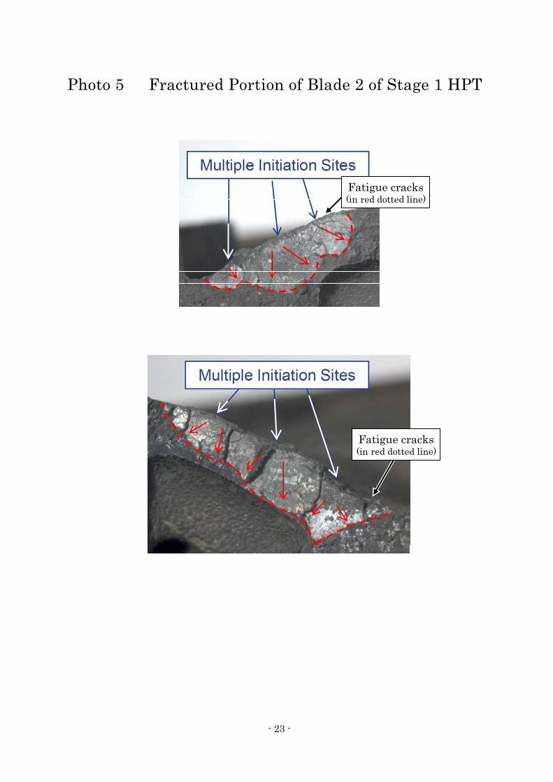
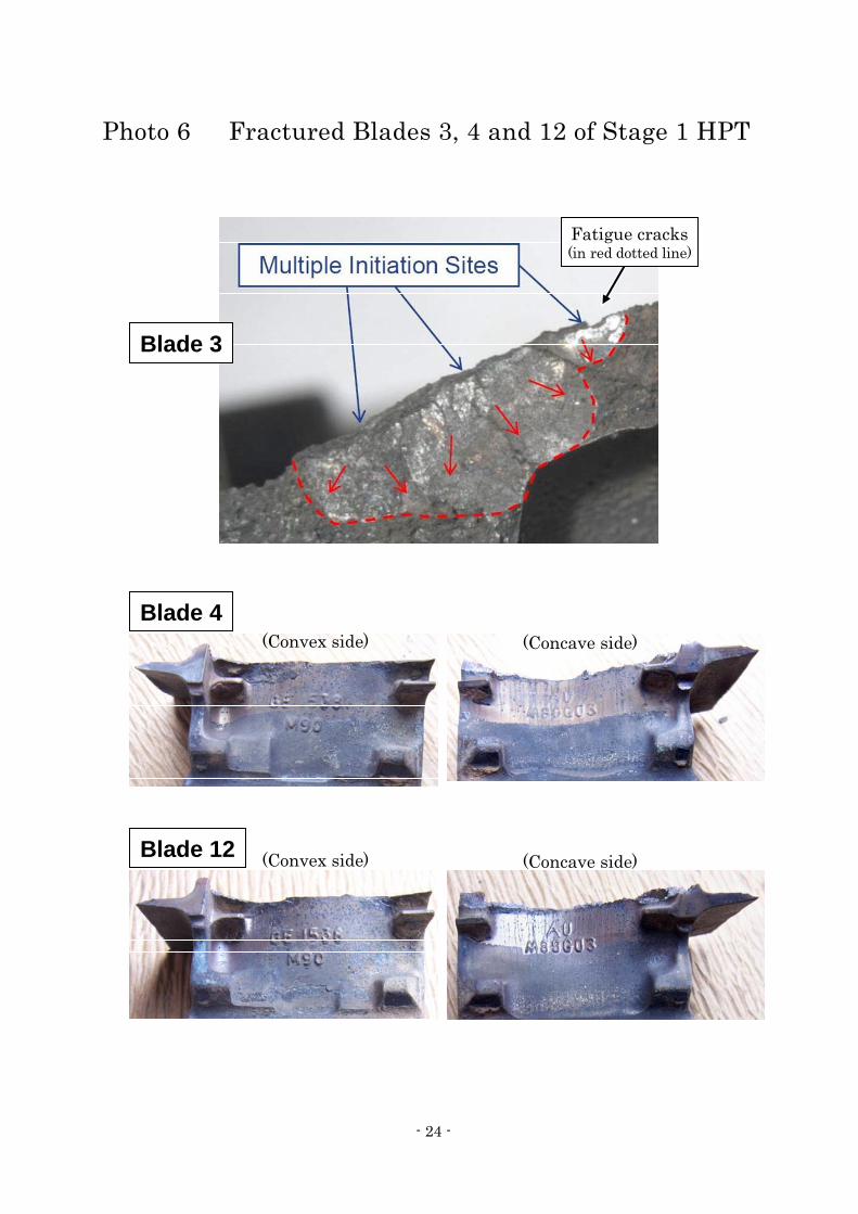
(2) Fatigue cracks with multiple initiation sites were found on the convex side surface of the shank area for the four blades which had been fractured below their platforms (blade 2 to 4 and 12). The size of each crack was as follows:
Blade 2 (two cracks): 0.260 in × 0.080 in (6.6 mm × 2.0 mm) and 0.370 in × 0.086 in (9.4 mm × 2.2 mm)
Blade 3: 0.280 in × 0.104 in (7.1 mm × 2.6 mm) Blade 4: 1.23 in × 0.44 in (31.2 mm × 11.2 mm) Blade 12: 1.27 in × 0.46 in (32.3 mm × 11.7 mm)
Areas in these four blades with no fatigue cracks had been fractured due to tensile rupture. (See Photo 5 Fractured Portion of Blade 2 of Stage 1 HPT, Photo 6 Fractured Blades
10
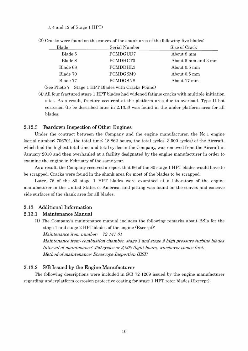
3, 4 and 12 of Stage 1 HPT)
(3) Cracks were found on the convex of the shank area of the following five blades: Blade Serial Number Size of Crack
Blade 5 PCMDGUD7 About 8 mm Blade 8 PCMDHCT0 About 5 mm and 3 mm Blade 68 PCMDDHL3 About 0.5 mm Blade 70 PCMDGSM9 About 0.5 mm Blade 77 PCMDGSN8 About 17 mm (See Photo 7 Stage 1 HPT Blades with Cracks Found)
(4) All four fractured stage 1 HPT blades had widened fatigue cracks with multiple initiation sites. As a result, fracture occurred at the platform area due to overload. Type II hot corrosion (to be described later in 2.13.3) was found in the under platform area for all blades.
2.12.3 Teardown Inspection of Other Engines
Under the contract between the Company and the engine manufacturer, the No.1 engine (serial number: 706701, the total time: 18,862 hours, the total cycles: 3,500 cycles) of the Aircraft, which had the highest total time and total cycles in the Company, was removed from the Aircraft in January 2010 and then overhauled at a facility designated by the engine manufacturer in order to examine the engine in February of the same year.
As a result, the Company received a report that 66 of the 80 stage 1 HPT blades would have to be scrapped. Cracks were found in the shank area for most of the blades to be scrapped.
Later, 76 of the 80 stage 1 HPT blades were examined at a laboratory of the engine manufacturer in the United States of America, and pitting was found on the convex and concave side surfaces of the shank area for all blades.
2.13 Additional Information 2.13.1 Maintenance Manual (1) The Company’s maintenance manual includes the following remarks about BSIs for the
stage 1 and stage 2 HPT blades of the engine (Excerpt): Maintenance item number: 72-141-01 Maintenance item: combustion chamber, stage 1 and stage 2 high pressure turbine blades Interval of maintenance: 400 cycles or 2,000 flight hours, whichever comes first. Method of maintenance: Borescope Inspection (BSI)
2.13.2 S/B Issued by the Engine Manufacturer
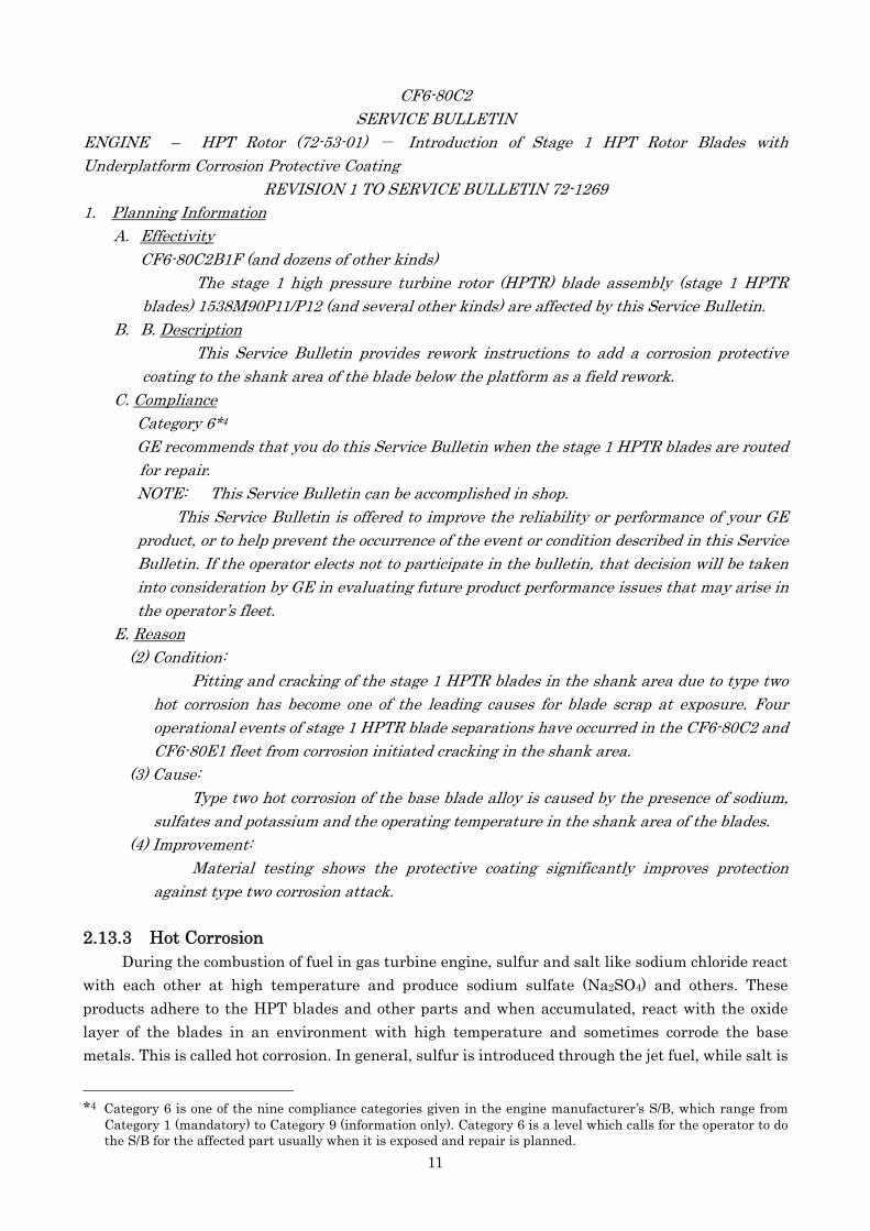
The following descriptions were included in S/B 72-1269 issued by the engine manufacturer regarding underplatform corrosion protective coating for stage 1 HPT rotor blades (Excerpt):
11
CF6-80C2 SERVICE BULLETIN
ENGINE – HPT Rotor (72-53-01) - Introduction of Stage 1 HPT Rotor Blades with Underplatform Corrosion Protective Coating
REVISION 1 TO SERVICE BULLETIN 72-1269 1. Planning Information
A. Effectivity CF6-80C2B1F (and dozens of other kinds)
The stage 1 high pressure turbine rotor (HPTR) blade assembly (stage 1 HPTR blades) 1538M90P11/P12 (and several other kinds) are affected by this Service Bulletin.
B. B. Description This Service Bulletin provides rework instructions to add a corrosion protective
coating to the shank area of the blade below the platform as a field rework. C. Compliance
Category 6*4 GE recommends that you do this Service Bulletin when the stage 1 HPTR blades are routed
for repair. NOTE: This Service Bulletin can be accomplished in shop.
This Service Bulletin is offered to improve the reliability or performance of your GE product, or to help prevent the occurrence of the event or condition described in this Service Bulletin. If the operator elects not to participate in the bulletin, that decision will be taken into consideration by GE in evaluating future product performance issues that may arise in the operator’s fleet.
E. Reason (2) Condition:
Pitting and cracking of the stage 1 HPTR blades in the shank area due to type two hot corrosion has become one of the leading causes for blade scrap at exposure. Four operational events of stage 1 HPTR blade separations have occurred in the CF6-80C2 and CF6-80E1 fleet from corrosion initiated cracking in the shank area.
(3) Cause: Type two hot corrosion of the base blade alloy is caused by the presence of sodium,
sulfates and potassium and the operating temperature in the shank area of the blades. (4) Improvement:
Material testing shows the protective coating significantly improves protection against type two corrosion attack.
2.13.3 Hot Corrosion
During the combustion of fuel in gas turbine engine, sulfur and salt like sodium chloride react with each other at high temperature and produce sodium sulfate (Na2SO4) and others. These products adhere to the HPT blades and other parts and when accumulated, react with the oxide layer of the blades in an environment with high temperature and sometimes corrode the base metals. This is called hot corrosion. In general, sulfur is introduced through the jet fuel, while salt is
*4 Category 6 is one of the nine compliance categories given in the engine manufacturer’s S/B, which range from
Category 1 (mandatory) to Category 9 (information only). Category 6 is a level which calls for the operator to do the S/B for the affected part usually when it is exposed and repair is planned.
12
introduced by ingesting air with high sodium content during over sea operations. Hot corrosion is usually divided into two categories. Type I hot corrosion tends to occur at
temperatures around 870 ºC (about 1,600 ºF). It does not depend on the amount of sulfur. But type II hot corrosion tends to occur at temperatures around 700 ºC (about 1,300 ºF), and the reaction speed increases as the amount of sulfur increases.
Type II hot corrosion creates pitting in a local area.
2.13.4 Comments from Engine Manufacturer The following comments were presented by the engine manufacturer in response to the JTSB’s
questions: (1) GE believes the corrosion begins when corrosive elements from the operating environment
(air pollution, de-icing fluid, etc.) are introduced/ingested into the engine. Since GE cannot determine the time or location of introduction/ingestion, we have no data to determine what is short term or long term. And, we cannot provide a recommendation for optimal replacement time for stage 1 HPT blades.
(2) GE has no information to show that trend data can be used to develop a type II hot corrosion evaluation standard. Type II hot corrosion of the HPT blade shanks has no noticeable affect on engine parameters.
(3) Detection of the presence of type II hot corrosion requires physical inspection of the blade shanks. GE has no knowledge of a method for detecting type II hot corrosion while the blades are installed in the engine. The shanks are not visible using BSI when installed in the engine.
(4) Regarding the possibility of the HPT blades being fractured due to type II hot corrosion if they do not apply the SB72-1269, SB72-1288 or SB72-1296, GE has presented related type of information via Fleet Highlites articles, Field Service Engineering team and Customer meetings.
(5) GE believes that the Category 6 classification for the SB 72-1269 was appropriate. The CF6-80C2 fleet has seen only three events of type II hot corrosion related HPT blade separation over eight years. GE has noted that this type of corrosion has been a piece-part inspection finding. GE has also noted that some customers have not seen corrosion, including another Japanese CF6-80C2 operator. The recommendation to complete inspection during the repair cycle is an appropriate recommendation.
(6) GE believes the appropriate recommendations and materials have been provided to manage type II hot corrosion in the shank area of HPT blades. GE will continue to monitor the fleet to insure that corrosion protection programs are effective.
(7) The temperature of the shank area of the stage 1 HPT blades can reach a temperature zone in which type II hot corrosion occurs.
3. ANALYSIS 3.1 Qualification of Personnel
PIC and FO held both valid airman competence certificates and valid aviation medical certificates.
3.2 Airworthiness Certificate of the Aircraft
13
The Aircraft had a valid airworthiness certificate and had been maintained and inspected as prescribed.
3.3 Relation to Meteorological Phenomena
It is considered highly probable that the meteorological condition at that time had no relation with this serious incident. 3.4 Damage to Engine 3.4.1 Partial Fracture of Stage 1 HPT Blades
As described in 2.12.2: (1) There were traces of fatigue in the fractured surfaces of all of the four fractured
blades, blades numbered 2 to 4 and 12. (2) Cracks were found in the shank area of five blades. (3) Signs of type II hot corrosion were seen in the shank area of all blades. (4) Debris accumulated in the shank area included sodium, potassium and sulfates.
Judging from this, it is considered highly probable that pitting had been caused by type II hot corrosion occurred in the shank area below the platform of the stage 1 HPT blades and cracks occurred from there and then, fatigue cracks widened with cycle stress applied on the blades following the engine’s operation, leading to the fractures of the blades.
As described in 2.12.2 (2), the fatigue cracks in blades 4 and 12 were seen widely in the fractured areas as a whole. Therefore, it is considered highly probable that initial fractures occurred in blades 4 or 12.
Traces of fatigue cracks were also seen in the fractured surfaces of blades 2 and 3, though less widely than in blades 4 or 12. Therefore, it is considered highly probable that following the fracture of blade 4, the neighboring blades 3 and 2, already weakened by existing fatigue cracks, fractured completely due to impact from blade 4. 3.4.2 Damage to NGV, Stage 1 HPT Shroud, Stage 2 HPT and LPT Sections
It is considered highly probable that the damage to the trailing edges of the NGV, as described in 2.3.2 (3) and 2.12.1 (3), occurred because broken blade fragments from the four fractured stage 1 HPT blades had damaged the stage 1 HPT shroud and at the same time, hit the trailing edge of NGV located just in front of the shroud.
It is considered highly probable that while damaging the outer circumference of the leading edges of the stage 2 HPT vanes, the broken pieces of the fractured blades hit the stage 2 HPT blades damaging them all. Then the broken blades fragments moved to the LPT with five stages in total damaging the LPT vanes and blades of each stage, eventually impacting and damaging the TRF before exiting the engine.
As described in 3.4.1, the propagation of the fatigue cracks in the shank area of the stage 1 HPT blades triggered the fractures of the blades. It is considered highly probable that damage to the NGV just in front of the stage 1 HPT blades, the stage 1 HPT shroud and components in the rear section had been caused secondarily. 3.4.3 Occurrence of Type II Hot Corrosion
Judging from the descriptions in 2.13.2 E (3), 2.13.3 and the following, it is considered probable that the shank area of the HPT blades had been in an environment where type II hot
14
corrosion easily occurs. (1) As described in 2.13.3, jet fuel contains a small amount of sulfur, while salt exists in the air. (2) As described in 2.12.2 (1), debris accumulated to the shank area had included sodium,
potassium and sulfates. (3) As described in 2.13.4 (7), because the shank area of the stage 1 HPT blades is not directly
exposed to combustion gas, it is considered somewhat likely that the temperature of the area was at around 700 ºC, a temperature zone where type II hot corrosion easily occurs.
It is considered somewhat likely that type II hot corrosion had been caused not only by sulfur contained in jet fuel but also by corrosion-triggering substances ingested from the air into the engine, as described in 2.13.4 (1). But the cause for the phenomenon could not be determined because the Aircraft’s operation had not concentrated on any specific region as described in 2.10. 3.4.4 Engine Control at the Time of Damage
It is considered highly probable that, since the Aircraft’s No.1 engine flowpath hardware was substantially damaged, part of the stage 1 HPT blades got fractured, N1 and N2 suddenly dropped, and as a result, the engine control unit automatically worked to drop FF in accordance with the established controlling schedule and this led to a drop in EGT.
Judging from the DFDR data, it is considered highly probable that after the Aircraft reached an altitude of about 7,000 feet, the throttle lever for the No.1 engine was retarded, the fuel control switch was set to the cut-off position and then the engine was shut down. 3.5 Possibilities of Early Trouble Finding
In accordance with the maintenance manual as described in 2.13.1, BSIs had been performed for the engine, but as described in 2.13.4 (3), the shank area of the HPT blades is not visible in BSI. Therefore, it is considered highly probable that the Company’s staff could not find indications of cracks or corrosion in the blade shanks.
As described in 2.10, there was no clear shift in the trend data which would have indicated abnormalities in the data about the engine since it was installed in the Aircraft as its No.1 engine. As described in 2.13.4 (2), it is considered probable that type II hot corrosion of the HPT blade shanks has no noticeable effect on engine parameters. Therefore, it is considered highly probable that only with the trend data, the Company and the engine manufacturer could not recognize a condition of deterioration of the shank area of the HPT blades.
Accordingly, the occurrence of type II hot corrosion and its progress cannot be easily confirmed in the shank area below the platform of the HPT blades. To confirm the condition of the area, all blades must be checked individually during a shop visit.
As described in 2.9, the engine manufacturer issued S/B 72-1269 recommending adding a corrosion protective coating on the shank area of the stage 1 HPT blades. As described in 2.13.2, the S/B had been given the compliance level of category 6, a less urgently needed level which does not require the operator to remove the engine prematurely to comply with the S/B. Since the S/B recommended doing the work when the stage 1 HPT blades are routed for repair, as described in 2.10, the Company had planned to perform the S/B 72-1269 during the next engine overhaul. As the compliance level is given as category 6, there may be no opportunity to confirm the condition of the shank area until it becomes necessary to repair the blades. But as described in 2.13.4 (5), the engine manufacturer believes that the Category 6 classification for the S/B was appropriate because the number of findings of similar phenomena was limited. As described in 2.9 (4) and (5), the engine
15
manufacturer had already released a new blade with corrosion protective coating applied for the shank area of the stage 1 HPT blades. 3.6 Responses after Engine Failure
Judging from the descriptions in 2.1.1 and 2.1.2, it is considered highly probable that, the crewmembers of the Aircraft did not feel any engine anomalies from the start of the engine to taxing to the takeoff roll. They recognized the occurrence of a No.1 engine failure when they saw messages on the instrument displays just after the Aircraft lifted off.
Judging from the descriptions in 2.1.1 and the DFDR data, it is considered highly probable that: PIC engaged the autopilot after correcting the veering of the heading of the Aircraft to the left following the No.1 engine failure. Meanwhile, the master warning was not activated. Therefore, PIC did not judge that the situation requires any urgent step, as the engine was already in an idle condition and that he continued to climb without shutting down the engine until the Aircraft reaches a fully safe altitude. 4. PROBABLE CAUSES
It is considered highly probable that this serious incident occurred as follows: When the Aircraft took off, one or more of the stage 1 HPT blades from the No.1 engine fractured at the shank area below the platform and the blade fragments went downstream and damaged the NGV, the stage 1 HPT shroud and components in the rear section.
It is considered highly probable that the fractures of part of the stage 1 HPT blades had been caused by pitting due to type II hot corrosion in the shank area below the platform and cracks grew from there, which led to fatigue cracks in the blades with cycle stress applied on them. 5. ACTIONS TAKEN Actions taken by the Company
After the occurrence of this serious incident, in order to prevent a recurrence of similar events, the Company has been gradually removing engines which have no corrosion protective coating on the shank area of the HPT blades and replacing these blades with new ones which have corrosion protective coating applied to the blade shank.
- 16 -
Figure 1 Estimated Flight Route
NaritaInternationalAirport
Runway B (2,500m – 60m
)
Occurrence point(about 140ft AGL)
21:53:48
Initiatetake-off run
ControlTower21:52:42
Take-off climb
NN
NaritaInternationalAirport
VENUS
20km0
N
NaritaInternationalAirport
VENUS
20km0 20km0
NN
Runway A (4,000m – 60m
)
Wind 160deg/03ktreported by Tower at 21:52Wind 160deg/03ktreported by Tower at 21:52

- 17 -
Figure 2 DFDR Records
EGT
N2
Eng
ine
vibr
atio
nTh
rottl
eLe
ver
Pos
ition
Mag
netic
Hea
ding
HPT
vibr
atio
nAu
topi
lot
Occurred at 21:53:48
about 140ft AGLabout 140ft AGL
N1
(hh:mm:ss)
FFC
AS
Hei
ght

- 18 -
Figure 3 Three Angle View of Boeing 747-400F
Unit : m 70.66
64.44
19.4

- 19 -
Figure 4 CF6-80C2 Engine
FWDFWD
FWDFWD
Stage 1HPT Blades Stage 2 HPT Blades
Stage 2 HPT Vanes
CombustionChamber
NGVs
(Reference : Study Guide)
(Reference : Study Guide)
LPTBlades
LPTVanes
S1 R1R2S2
S1 R1 R2S2
S:Stator vanesR:Rotor blades
see below
Stage 1 HPT Shroud
Stage 1 HPT Rotor
TRFLPC HPC
HPT(2 stages)
LPT(5 stages)

- 20 -
Photo 1 Serious Incident Aircraft
Photo 2 Dismounted No.1 Engine
No.1 Engine

- 21 -
Photo 3 Stage 1 HPT Rotor
FWD
FWD
Blade 2, 3, 4 Blade 12
All blade-tipswere damagedStage 1 HPT Blades:80

- 22 -
Photo 4 Damaged Stage 1 HPT Blades
41
23
1220 8040 60
7770
68
21 41 61
58
- 23 -
Photo 5 Fractured Portion of Blade 2 of Stage 1 HPT
Fatigue cracks(in red dotted line)
Fatigue cracks(in red dotted line)
- 24 -
Photo 6 Fractured Blades 3, 4 and 12 of Stage 1 HPT
Blade 3
Blade 4
Blade 12
(Convex side) (Concave side)
(Convex side) (Concave side)
Fatigue cracks(in red dotted line)
- 25 -
Photo 7 Stage 1 HPT Blades with Cracks Found
Blade 5
Blade 8
Blade 77
Platform
Shank
Blade 68
Blade 70
- 26 -
Photo 8 Stage 1 HPT Blade (Unused)
Part Number : 1538M90P12
TrailingEdge
LeadingEdge
Shank
Platform
Coolingholes
Air
foil
(Convex side) (Concave side)
Coolingholes